JP3698877B2 - Sealed container for electrical equipment - Google Patents
Sealed container for electrical equipment Download PDFInfo
- Publication number
- JP3698877B2 JP3698877B2 JP28032797A JP28032797A JP3698877B2 JP 3698877 B2 JP3698877 B2 JP 3698877B2 JP 28032797 A JP28032797 A JP 28032797A JP 28032797 A JP28032797 A JP 28032797A JP 3698877 B2 JP3698877 B2 JP 3698877B2
- Authority
- JP
- Japan
- Prior art keywords
- flange
- flange portion
- seal packing
- annular
- side facing
- Prior art date
- Legal status (The legal status is an assumption and is not a legal conclusion. Google has not performed a legal analysis and makes no representation as to the accuracy of the status listed.)
- Expired - Lifetime
Links
Images


Landscapes
- Closures For Containers (AREA)
- Housings And Mounting Of Transformers (AREA)
Description
【0001】
【発明の属する技術分野】
本発明は、ケース本体と蓋部材との間にシールパッキンを備えた電気機器用密封容器に関するものである。
【0002】
【従来の技術】
実開昭58−56251号公報には、開口部に全周にわたって連続した環状のフランジ部が設けられたケース本体と、弾性材料から構成されてフランジ部に嵌合される環状のシールパッキンと、シールパッキンをフランジ部に押し付け且つケース本体の開口部を塞ぐようにケース本体に取付けられた蓋部材とを具備する電気機器用密封容器と、この密封容器に用いるシールパッキンが開示されている。この公報の第4図に示された構造では、フランジ部が上に向かって凸となるように湾曲した横断面形状を有しており、またシールパッキンはこのフランジの湾曲した外表面に接着剤を用いて貼付けられている。更にその第7図(b)に示されたシールパッキンは、外表面の中央部に凸部(厚肉部)を備えている。この凸部が圧縮変形されてシール部を構成する。
【0003】
また実公平2−19661号公報の第1図〜第3図には、それぞれ油入電気機器用密封容器のケース本体の開口部に設けた環状のフランジ部に嵌合構造により固定されるシールパッキンの例が示されている。環状のフランジ部はラッパ状に広がった形状を有しており、シールパッキンにはフランジ部が挿入されて嵌合される比較的深い環状の溝部が形成されている。
【0004】
【発明が解決しようとする課題】
実開昭58−56251号公報に示されたシール構造では、シールパッキンの固定に接着剤を必要とするために、シールパッキンの取付作業が面倒になる問題がある。また実公平2−19661号公報に示されるようなシール構造では、シール性能があまり高くない。この原因の一つは、ケース本体の外側に取付金具等が溶接される際の熱でケース本体の開口部の形状が歪み、この歪みによって嵌合されたフランジ部とシールパッキンとの間にシール性能を低下させるような隙間が形成されることである。また別の原因は、ケース本体や蓋部材が亜鉛メッキ等でメッキされ、更にその上に樹脂塗料による塗装が施されると、その表面が粗くなって、これらの部材とシールパッキンとの間の密着性が悪くなることである。
【0005】
本発明の目的は、シールパッキンの取付けが容易で、しかもシール性の高い電気機器用密封容器を提供することにある。
【0006】
【課題を解決するための手段】
本発明は、開口部に全周にわたって連続する環状のフランジ部が設けられたケース本体と、弾性材料から形成されてフランジ部に嵌合される環状のシールパッキンと、シールパッキンをフランジ部に押し付け且つケース本体の開口部を塞ぐようにケース本体に取付けられた蓋部材とを具備する密封容器を対象とする。この密封容器が変圧器等の電気機器を収納する電気機器用密封容器の場合には、ケース本体及び蓋部材は金属製である。そしてこの場合に電気機器用密封容器の内部に絶縁油等が充填される場合には、フランジ部の形状は上に向かって凸となるように湾曲した横断面形状を有しているのが好ましい。そして耐蝕性の向上ために、ケース本体及び蓋部材はそれぞれ亜鉛メッキ等によりメッキされた後にその上に塗装が施されていてもよい。
【0007】
本発明で用いるシールパッキンは、フランジ部の環状の外表面と対向する環状のフランジ側対向面部と、フランジ側対向面部と対向する位置にあって蓋部材の内壁面と対向する蓋側対向面部と、フランジ部の環状の縁部と係合する係合部とを有している。そしてシールパッキンのフランジ側対向面部には、フランジ側対向面部の全周にわたって即ちフランジ対向面部に沿って延び且つフランジ部側に向かって突出する同心状に配置された環状の複数の下側凸部が一体に設けられている。またシールパッキンの蓋側対向面部には、蓋側対向面部に沿って延び且つ蓋部材側に向かって突出する同心状に配置された環状の複数の上側凸部が一体に設けられている。なお、フランジ側対向面部、係合部並びに複数の下側凸部は、係合部がフランジ部の縁部と係合し且つ複数の下側凸部がフランジ部の外表面と接触した状態において、フランジ部にシールパッキンが嵌合された状態になるように形状を定めるのが好ましい。更に複数の下側凸部及び複数の上側凸部は、蓋部材がケース本体に取付けられた状態で圧縮変形されてシール部を構成する形状を有している。
【0008】
本発明の構造によれば、フランジ部の縁部とシールパッキンとの係合により、接着剤を用いることなくシールパッキンをケース本体のフランジ部に取付けることができる。その上、シールパッキンにはフランジ部と接触する複数の下側凸部と、蓋部材と接触する複数の上側凸部とが一体に設けられている。これら下側凸部及び上側凸部の突出寸法、数を任意に設定すれば、ケース本体の開口部に歪みがあったり、ケース本体の表面が粗れていても、フランジ部とシールパッキンとの間及び蓋部材とシールパッキンとの間にそれぞれ同心状に複数のシールが構成されることになってシール性が高くなる。そのためシールパッキンをケース本体のフランジ部に嵌合させる構造を採用してもシール性能を高く維持することができる。また凸部によりシール部を構成すると、蓋部材のケース本体への締め付け力を小さくしてもよくなるため、その分シールパッキンに加わるストレスが小さくなってシールパッキンの寿命が延びる。
【0009】
特にフランジ部が上に向かって凸となるように湾曲した横断面形状を有している場合には、複数の上側凸部は、フランジ部の頂点よりも内側に位置する上側凸部の数がフランジ部の頂点よりも外側に位置する上側凸部の数よりも多くなるように設けるのが好ましい。これは次のような理由による。まずフランジ部の湾曲加工には加工誤差がつきものであり、この加工誤差によってシールパッキンが部分的に外側に引っ張られる場合がある。そしてシールパッキンが部分的に外側に引っ張られた部分では、本来ならばフランジ部の頂点よりも内側にある1以上の上側凸部が頂点よりも外側に移動している場合が多い。フランジ部の頂点よりも内側に位置する上側凸部の数がフランジ部の頂点よりも外側に位置する上側凸部の数よりも少ない場合には、この1以上の上側凸部の移動によりシール性能が低下する。そこで前述のように、フランジ部の頂点よりも内側に位置する上側凸部の数を増やしておけば、前述のような上側凸部の移動があってもシール性能が低下するのを防止できる。
【0010】
フランジ部の横断面形状がほぼ円弧状を呈している場合には、フランジ部に嵌合する前のシールパッキンの蓋側対向面部及びフランジ側対向面部の横断面形状を、フランジ部の横断面形状とほぼ同心状になるようにほぼ円弧状を呈するように定めるのが好ましい。このようにするとフランジ部に多少の加工誤差があっても、フランジ部に嵌合された状態におけるシールパッキンからの上側凸部の突出寸法はほとんど変わらない。言い換えると、シールパッキンが部分的に外側に引っ張られて上側凸部が外側に移動してもフランジ部の頂点に対応する位置に来る次の上側凸部の突出寸法もほぼ同じになる。そのためにシール性能が変わることがないのである。
【0011】
特にフランジ部の横断面形状が上に向かって凸となるような円弧状の横断面形状を呈している場合で、複数の下側凸部を第1及び第2の凸部により構成し、複数の上側凸部を第3及び第4の凸部により構成する場合には、第1乃至第4の凸部を次のように配置するのが好ましい。すなわちシールパッキンがフランジ部に嵌合された状態で、第1の凸部と第2の凸部をフランジ部の頂点を通る仮想筒状面の両側に該仮想筒状面からほぼ等しい第1の間隔寸法を開けるように配置する。なおこの仮想筒状面は、ケース本体と実質的に同心状になる。またシールパッキンがフランジ部に嵌合された状態で、第3の凸部と第4の凸部を前述の仮想筒状面の両側に該仮想筒状面からほぼ等しい第2の間隔寸法を開けるように配置する。このように第1乃至第4の凸部を配置すると、第1乃至第4の凸部と対向部材(フランジ部または蓋部材)に接触させることができる。特に、この場合に、第1の間隔寸法を第2の間隔寸法より小さくすると、シールパッキンがフランジ部と蓋部材との間に挟持される際に、第1乃至第4の凸部がそれぞれ確実に圧縮変形して、シール性能が高くなる。
【0012】
なお係合部を複数の係合片により構成し、間隔をあけてフランジ部の縁部と係合させる構造を採用してもよいが、係合部をフランジ部の縁部と連続的に係合するように環状に形成すると、この係合部でもシール部が構成されるためシール性能が更に高くなる。
【0013】
第1及び第2の凸部並びに第3及び第4の凸部は、それぞれがシール部を構成すればよいが、成形性及びシール性を考慮すると、それぞれ同心状に配置するのが好ましい。
【0014】
【発明の実施の形態】
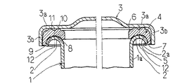
以下図面を参照して、本発明の実施の形態の一例を詳細に説明する。図1は、本発明を変圧器の密封容器(電気機器用密封容器)に適用した実施の形態の一例の要部の部分省略断面図である。また図2は、この実施の形態で用いるシールパッキンの部分省略断面図であり、図3はこのシールパッキンの一部を拡大した横断面図である。
【0015】
図1において、1は鉄製のケース本体であり、円筒状の筒部1aの開口部には全周にわたって連続する環状のフランジ部2が一体に設けられている。ケース本体には、亜鉛メッキされた後に、その上に樹脂塗料がカチオン塗装されている。図示していないが、ケース本体の外側には取付金具等の鉄製の金具が溶接により固定されている。フランジ部2は、上(開口部が開口する方向)に向かって凸となるように円弧状に湾曲した横断面形状を有している。ちなみにケース本体1に用いられる鉄板の厚みが約2mmで、ケース本体1の筒部1aの直径が500mmであるとした場合、フランジ部2の円弧の半径は7〜8mm程度となる。
【0016】
また図1において、3は鉄製の蓋部材であり、この蓋部材3にも亜鉛メッキされた後に、その上に樹脂塗料がカチオン塗装されている。この蓋部材3はケース本体の開口部と対向する板状部3aと、この板状部3aの外周に一体に設けられて板状部3aとほぼ直交する方向に延びる環状の鍔部3bとから構成されている。ケース本体1のフランジ部2と対向する蓋部材3の板状部3aの内壁部はフラットに形成されている。なお図示していないが、蓋部材3をケース本体1に対して取付ける取付構造は周知の構造である。
【0017】
4はニトリルゴム等の弾性材料から形成されてケース本体1のフランジ部2に嵌合される環状のシールパッキンである。なおこのシールパッキン4には、織布等の補強部材が埋設されていてもよいのは勿論である。シールパッキン4は上に向かって凸状に湾曲したフランジ部2の環状の外表面と対向する環状のフランジ側対向面部5と、フランジ側対向面部5と対向する位置にあって蓋部材3の板状部3aの内壁面と対向する蓋側対向面部6と、フランジ部2の環状の縁部2aと係合する係合部7とを有している。
【0018】
図3に拡大して示すように、フランジ側対向面部5は、環状の平面部5aとフランジ部2の外表面に沿うように湾曲する環状の湾曲部5bとを有している。シールパッキン4のフランジ側対向面部5の湾曲部5bには、フランジ側対向面部5の全周にわたって延び即ちフランジ側対向面部5に沿って延び且つフランジ部2側に向かって(フランジ側対向面部5から離れる方向に向かって)突出する環状の第1の凸部8と、この第1の凸部8の外側(ケース本体1の径方向外側)に位置してフランジ側対向面部5の全周にわたって延び且つフランジ部2側に向かって突出する環状の第2の凸部9とが一体に設けられている。これら第1及び第2の凸部8及び9が、下側凸部を構成している。またシールパッキン4の蓋側対向面部6には、蓋側対向面部6の全周にわたって延び且つ蓋部材3側に向かって(蓋側対向面部6から離れる方向に向かって)突出する環状の第3の凸部10とこの第3の凸部10の外側に位置して蓋側対向面部6の全周にわたって延び且つ蓋部材3側に向かって突出する環状の第4の凸部11とが一体に設けられている。なお第3及び第4の凸部10及び11が、上側凸部を構成している。
【0019】
第1及び第2の凸部8及び9は、フランジ部2の頂点を通る仮想筒状面12の両側に等しい第1の間隔寸法L1を開けるように同心状に配置されており、また第3の凸部10と第4の凸部11は仮想筒状面12の両側に該仮想筒状面からほぼ等しい第2の間隔寸法L2を開けるように同心上に配置されている。そしてこの例では、第1の間隔寸法L1を約2.5mm、また第2の間隔寸法L2を約3mmとして、第1の間隔寸法L1を第2の間隔寸法L2よりも小さくしている。ちなみにこの例の場合の第1及び第2の凸部8及び9の外面の曲率半径は約0.5mmであり、第3及び第4の凸部10及び11の外面の曲率半径は約1mmである。
【0020】
発明者は、当初シールパッキンのフランジ側対向面部5と蓋側対向面部6とにそれぞれ1つずつ環状の凸部を設けることを考えた。しかしながら凸部が1つではシール性が必ずしも十分でないことが分かった。そこで本発明では、前述のようにフランジ側対向面部5と蓋側対向面部6にそれぞれ2つずつ凸部を設けたのである。
【0021】
係合部7は、ケース本体1のフランジ部2の縁部2aと全周にわたって連続的に係合するように環状を成している。この係合部7は横断面形状がフック状を呈する形状を有している。なおこの例では、シールパッキン4のフランジ側対向面部5、係合部7並びに第1及び第2の凸部8及び9は、係合部7がフランジ部2の縁部2aと係合し且つ第1及び第2の凸部8及び9がフランジ部2の外表面と接触した状態において、フランジ部2にシールパッキン4がしっかりと嵌合して容易にはずれない状態になるように形状寸法が定められている。また第1乃至第4の凸部8乃至11は、シールパッキン4をケース本体1のフランジ部2に押し付け且つケース本体1の開口部を塞ぐように蓋部材3がケース本体1に取付けられた状態で、それぞれ圧縮変形してシール部を構成するように形状が定められている。なおこの例では、シールパッキン4の内部寸法は、フランジ部2の外部寸法よりも約2.5%小さく定められている。第1及び第2の凸部8及び9によってフランジ部2とシールパッキン4との間の二重シールが構成され、第3及び第4の凸部10及び11によってシールパッキン4と蓋部材3との間の二重シールが構成されている。
【0022】
上記例では、第1及び第2の凸部8及び9間の第1の間隔寸法L1を第3及び第4の凸部10及び11間の第2の間隔寸法L2よりも小さくすることにより、シールパッキン4がフランジ部2と蓋部材3との間に挟持された際における第1乃至第4の凸部の圧縮変形を確実なものとして、シール性能を高めている。しかしながら、フランジ部2の曲率半径が大きくなる場合には、この第1の間隔寸法と第2の間隔寸法の関係を逆の関係にしてもよい。さらにシールパッキン4の弾性率及び第1乃至第4の凸部の突出寸法を適宜に選択することにより、第1の間隔寸法と第2の間隔寸法を実質的に一致させることも可能である。
【0023】
また上記例では、係合部7を環状に形成しているが、係合部を周方向に間隔をあけて配置した複数の係合片によって構成してもよいのは勿論である。
【0024】
図4は、本発明で用いることができる別のシールパッキン24の一部の横断面形状を示している(なお理解を容易にするために断面であることを示すハッチングは省略してある)。このシールパッキン24は図1に示す横断面形状が円弧状をなすフランジ部2に取付けるのに適しており、図1のシールパッキン4と置き換えて使用できるものである。図1のシールパッキン4との寸法の差を明確にするために、図4には想像線でシールパッキン4の横断面形状を記載してある。そして図4には、図1〜図3に示したシールパッキン4と同様の部分に、図1〜図3に付した符号に20の数を加えた数の符号を付してある。
【0025】
このシールパッキン24は上に向かって凸状に湾曲したフランジ部2(図1)の環状の外表面と対向する環状のフランジ側対向面部25と、フランジ側対向面部25と対向する位置にあって蓋部材3(図1)の板状部3a(図1)の内壁面と対向する蓋側対向面部26と、フランジ部2(図1)の環状の縁部2a(図1)と係合する係合部27とを有している。フランジ側対向面部25は、環状の平面部25aと円弧状に湾曲したフランジ部2(図1)の外表面に沿うように湾曲した横断面形状が円弧状の環状の湾曲部25bとを有している。シールパッキン24のフランジ側対向面部25の湾曲部25bには、フランジ側対向面部5の全周にわたって延び且つフランジ部2側に向かって(フランジ側対向面部25から離れる方向に向かって)突出する環状の8個の下側凸部28が一体に設けられている。これら下側凸部28の横断面形状は下側に向かって凸となる三角形形状を呈している。またフランジ部2の頂点を通る仮想円筒状面32と合致する位置に1つの下側凸部28が設けられ、その内側に4つの下側凸部28が設けられ、その外側に3つの下側凸部28が設けられている。言い換えると、フランジ部2の頂点よりも内側の下側凸部28の数のほうが、外側の下側凸部28の数よりも多くなっている。
【0026】
またシールパッキン24の蓋側対向面部26は、フランジ側対向面部25の湾曲部25bと同心状に湾曲しており、その上には蓋側対向面部26の全周にわたって延び且つ蓋部材3(図1)側に向かって(蓋側対向面部26から離れる方向に向かって)突出する環状の13個の上側凸部30…が一体に設けられている。これらの上側凸部30…も、横断面形状が上に向かって凸となる三角形形状を呈しており、すべて同心的に配置されている。上側凸部30間の間隔はほぼ一定である。上側凸部30…の突出寸法は、下側凸部28の突出寸法よりも約1.5倍程大きくなっている。フランジ部2(図1)の頂点を通る仮想円筒状面32と合致する位置に1つの上側凸部30が設けられ、その内側に7つの上側凸部30が設けられ、その外側に5つの上側凸部30が設けられている。言い換えると、フランジ部2の頂点よりも内側の上側凸部30の数のほうが、外側の下側凸部30の数よりも多くなっている。
【0027】
フランジ部の頂点よりも内側に位置する上側凸部30の数をフランジ部の頂点よりも外側に位置する上側凸部30の数よりも多くすると、フランジ部の湾曲加工により生じる加工誤差によってシールパッキン24が部分的に外側に引っ張られる場合があっても、シールパッキン24が部分的に外側に引っ張られた部分では、本来ならばフランジ部の頂点よりも内側にある1以上の上側凸部30が頂点よりも外側に移動する。フランジ部の頂点よりも内側に位置する上側凸部30の数がフランジ部の頂点よりも外側に位置する上側凸部30の数よりも少ない場合には、この1以上の上側凸部の移動によりシール性能が低下する。
【0028】
上記例は、本発明を電気機器用密封容器に適用したものであるが、本発明はその他の密封容器にも当然にして適用できる。
【0029】
【発明の効果】
本発明によれば、フランジ部の縁部とシールパッキンとの係合により、接着剤を用いることなくシールパッキンをケース本体のフランジ部に取付けることができる。またシールパッキンにフランジ部と接触する複数の下側凸部と蓋部材と接触する複数の上側凸部とを一体に設けているため、ケース本体の開口部に歪みがあったり、ケース本体の表面が粗れていても、フランジ部とシールパッキンとの間及び蓋部材とシールパッキンとの間にそれぞれ複数のシールを構成することができて、シールパッキンをケース本体のフランジ部に嵌合させる構造を採用してもシール性能を高く維持することができる利点がある。
【図面の簡単な説明】
【図1】 本発明を変圧器の密封容器に適用した実施の形態の一例の要部の部分省略断面図である。
【図2】 図1の実施の形態で用いるシールパッキンの部分省略断面図である。
【図3】 図2のシールパッキンの一部の拡大横断面図である。
【図4】 本発明で用いることができる別のシールパッキンの一部の横断面形状を示す図である。
【符号の説明】
1 ケース本体
2 フランジ部
3 蓋部材
4,24 シールパッキン
5,25 フランジ側対向面部
6,26 蓋側対向面部
7,27 係合部
8,9,28 下側凸部
10,11,30 上側凸部[0001]
BACKGROUND OF THE INVENTION
The present invention relates to sealed containers for electrical equipment provided with a seal packing between the case body and the lid member.
[0002]
[Prior art]
Japanese Utility Model Laid-Open No. 58-56251 discloses a case main body provided with an annular flange portion that is continuous over the entire circumference of the opening, an annular seal packing that is made of an elastic material and is fitted to the flange portion, There are disclosed a sealed container for an electric device including a lid member attached to a case body so as to press the seal packing against a flange portion and close an opening of the case body, and a seal packing used for the sealed container. In the structure shown in FIG. 4 of this publication, the flange portion has a curved cross-sectional shape that is convex upward, and the seal packing is bonded to the curved outer surface of the flange. It is pasted using. Furthermore, the seal packing shown in FIG. 7 (b) has a convex portion (thick portion) at the center of the outer surface. This convex portion is compressed and deformed to constitute a seal portion.
[0003]
FIGS. 1 to 3 of Japanese Utility Model Publication No. 2-19661 each show a seal packing fixed to an annular flange portion provided in an opening of a case body of a sealed container for oil-filled electrical equipment by a fitting structure. An example of is shown. The annular flange portion has a shape spreading in a trumpet shape, and a relatively deep annular groove portion into which the flange portion is inserted and fitted is formed in the seal packing.
[0004]
[Problems to be solved by the invention]
In the seal structure disclosed in Japanese Utility Model Laid-Open No. 58-56251, since an adhesive is required for fixing the seal packing, there is a problem that the mounting work of the seal packing becomes troublesome. In addition, the sealing structure as shown in Japanese Utility Model Publication No. 2-19661 has a low sealing performance. One of the causes is that the shape of the opening of the case body is distorted by the heat generated when the mounting brackets are welded to the outside of the case body, and the seal is formed between the flange portion and the seal packing fitted by this distortion. A gap that reduces the performance is formed. Another cause is that when the case body and the lid member are plated with zinc plating or the like and further coated with a resin paint, the surface becomes rough, and between these members and the seal packing, Adhesiveness is deteriorated.
[0005]
An object of the present invention, the mounting of the seal packing is easy, yet to provide a high have electrical equipment for sealed containers of sealability.
[0006]
[Means for Solving the Problems]
The present invention includes a case main body provided with an annular flange portion that is continuous over the entire circumference in the opening, an annular seal packing that is formed of an elastic material and is fitted to the flange portion, and presses the seal packing against the flange portion. In addition, a sealed container including a lid member attached to the case main body so as to close the opening of the case main body is an object. In the case where the sealed container is a sealed container for electrical equipment that houses electrical equipment such as a transformer, the case body and the lid member are made of metal. In this case, when the inside of the sealed container for electrical equipment is filled with insulating oil or the like, it is preferable that the shape of the flange portion has a cross-sectional shape curved so as to be convex upward. . And in order to improve corrosion resistance, the case main body and the lid member may each be coated by coating after being plated by galvanization or the like.
[0007]
The seal packing used in the present invention includes an annular flange-side facing surface portion that faces the annular outer surface of the flange portion, a lid-side facing surface portion that faces the flange-side facing surface portion and faces the inner wall surface of the lid member. And an engaging portion that engages with the annular edge of the flange portion. The flange-side facing surface portion of the seal packing has a plurality of concentrically arranged lower convex portions that extend along the entire circumference of the flange-side facing surface portion, that is, along the flange-facing surface portion and project toward the flange portion side. Are provided integrally. In addition, a plurality of concentrically arranged upper convex portions that extend along the lid side facing surface portion and project toward the lid member side are integrally provided on the lid side facing surface portion of the seal packing. The flange side facing surface part, the engaging part, and the plurality of lower convex parts are in a state where the engaging part is engaged with the edge of the flange part and the plurality of lower convex parts are in contact with the outer surface of the flange part. The shape is preferably determined so that the seal packing is fitted to the flange portion. Furthermore, the plurality of lower protrusions and the plurality of upper protrusions have a shape that forms a seal portion by being compressed and deformed in a state where the lid member is attached to the case body.
[0008]
According to the structure of the present invention, the seal packing can be attached to the flange portion of the case main body without using an adhesive by the engagement between the edge portion of the flange portion and the seal packing. In addition, the seal packing is integrally provided with a plurality of lower convex portions that come into contact with the flange portion and a plurality of upper convex portions that come into contact with the lid member. If the projecting dimensions and number of these lower and upper projections are set arbitrarily, even if the opening of the case body is distorted or the surface of the case body is rough, the flange portion and the seal packing A plurality of seals are formed concentrically between each other and between the lid member and the seal packing, thereby improving the sealing performance. Therefore, high sealing performance can be maintained even if a structure in which the seal packing is fitted to the flange portion of the case main body is employed. Further, when the seal portion is formed by the convex portion, the tightening force of the lid member to the case main body may be reduced, so that the stress applied to the seal packing is reduced correspondingly and the life of the seal packing is extended.
[0009]
In particular, when the flange portion has a cross-sectional shape curved so as to be convex upward, the plurality of upper convex portions has the number of upper convex portions located on the inner side of the apex of the flange portion. It is preferable to provide more than the number of the upper convex parts located outside the apex of the flange part. This is due to the following reason. First, a bending error is inherent in the bending process of the flange portion, and the seal packing may be partially pulled outward due to the processing error. In the portion where the seal packing is partially pulled outward, one or more upper convex portions which are originally inside the apex of the flange portion are often moved outward from the apex. When the number of the upper convex portions located inside the apex of the flange portion is smaller than the number of the upper convex portions located outside the apex of the flange portion, the sealing performance is obtained by the movement of the one or more upper convex portions. Decreases. Therefore, as described above, if the number of the upper convex portions positioned on the inner side of the apex of the flange portion is increased, it is possible to prevent the sealing performance from being deteriorated even if the upper convex portion is moved as described above.
[0010]
If the cross-sectional shape of the flange portion is almost arc-shaped, the cross-sectional shape of the lid-side facing surface portion and flange-side facing surface portion of the seal packing before fitting into the flange portion is the same as the cross-sectional shape of the flange portion. It is preferable to define a substantially arc shape so as to be substantially concentric. In this way, even if there is some processing error in the flange portion, the projecting dimension of the upper convex portion from the seal packing in a state where it is fitted to the flange portion hardly changes. In other words, even if the seal packing is partially pulled outward and the upper convex portion moves outward, the projecting dimension of the next upper convex portion that comes to a position corresponding to the apex of the flange portion is substantially the same. Therefore, the sealing performance does not change.
[0011]
In particular, when the cross-sectional shape of the flange portion has an arcuate cross-sectional shape that is convex upward, a plurality of lower convex portions are configured by the first and second convex portions, In the case where the upper convex portion is constituted by the third and fourth convex portions, it is preferable to arrange the first to fourth convex portions as follows. That is, in a state where the seal packing is fitted to the flange portion, the first convex portion and the second convex portion are substantially equal from the virtual cylindrical surface to the both sides of the virtual cylindrical surface passing through the apex of the flange portion. Arrange so that the gap dimension is opened. The virtual cylindrical surface is substantially concentric with the case body. Further, in a state where the seal packing is fitted to the flange portion, the third convex portion and the fourth convex portion are opened on both sides of the above-described virtual cylindrical surface with a second interval dimension substantially equal from the virtual cylindrical surface. Arrange as follows. When the first to fourth convex portions are arranged in this manner, the first to fourth convex portions and the opposing member (flange portion or lid member) can be brought into contact with each other. In particular, in this case, if the first gap dimension is smaller than the second gap dimension, the first to fourth protrusions are surely secured when the seal packing is sandwiched between the flange portion and the lid member. Compressive deformation to improve sealing performance.
[0012]
It is possible to adopt a structure in which the engaging part is constituted by a plurality of engaging pieces and is engaged with the edge of the flange part at intervals, but the engaging part is continuously engaged with the edge of the flange part. If it is formed in an annular shape so as to match, the sealing performance is further enhanced since the sealing portion is also formed in this engaging portion.
[0013]
Each of the first and second convex portions and the third and fourth convex portions only needs to constitute a seal portion. However, in consideration of moldability and sealability, the first and second convex portions are preferably arranged concentrically.
[0014]
DETAILED DESCRIPTION OF THE INVENTION
Hereinafter, an example of an embodiment of the present invention will be described in detail with reference to the drawings. FIG. 1 is a partially omitted cross-sectional view of a main part of an example of an embodiment in which the present invention is applied to a sealed container (a sealed container for electrical equipment) of a transformer. 2 is a partially omitted cross-sectional view of the seal packing used in this embodiment, and FIG. 3 is an enlarged cross-sectional view of a part of this seal packing.
[0015]
In FIG. 1, reference numeral 1 denotes an iron case main body, and an annular flange portion 2 that is continuous over the entire circumference is integrally provided in an opening portion of a cylindrical tube portion 1a. After the case body is galvanized, a resin paint is cationically coated thereon. Although not shown, an iron fitting such as a fitting is fixed to the outside of the case body by welding. The flange portion 2 has a cross-sectional shape curved in an arc shape so as to protrude upward (in the direction in which the opening portion opens). Incidentally, when the thickness of the iron plate used for the case main body 1 is about 2 mm and the diameter of the cylindrical portion 1a of the case main body 1 is 500 mm, the radius of the arc of the flange portion 2 is about 7 to 8 mm.
[0016]
In FIG. 1, reference numeral 3 denotes an iron lid member. After the lid member 3 is also galvanized, a resin coating is cationically coated thereon. The lid member 3 includes a plate-like portion 3a facing the opening of the case body, and an annular flange portion 3b provided integrally with the outer periphery of the plate-like portion 3a and extending in a direction substantially orthogonal to the plate-like portion 3a. It is configured. The inner wall portion of the plate-like portion 3a of the lid member 3 facing the flange portion 2 of the case body 1 is formed flat. Although not shown, the attachment structure for attaching the lid member 3 to the case body 1 is a known structure.
[0017]
[0018]
As shown in an enlarged view in FIG. 3, the flange-side facing
[0019]
The first and second
[0020]
The inventor initially considered providing an annular convex portion on each of the flange-side facing
[0021]
The engaging
[0022]
In the above example, by making the first distance dimension L1 between the first and second
[0023]
Moreover, in the said example, although the
[0024]
FIG. 4 shows a cross-sectional shape of a part of another seal packing 24 that can be used in the present invention (the hatching indicating the cross section is omitted for easy understanding). The seal packing 24 is suitable for being attached to the flange portion 2 having a circular cross section shown in FIG. 1, and can be used in place of the seal packing 4 of FIG. In order to clarify the dimensional difference from the seal packing 4 in FIG. 1, the cross-sectional shape of the seal packing 4 is shown in FIG. In FIG. 4, the same reference numerals as those shown in FIGS. 1 to 3 are given the same reference numerals as those shown in FIGS.
[0025]
The seal packing 24 is located at a position facing the flange-side facing
[0026]
The lid-side facing
[0027]
When the number of the
[0028]
In the above example, the present invention is applied to a sealed container for electrical equipment, but the present invention can naturally be applied to other sealed containers.
[0029]
【The invention's effect】
According to the present invention, the seal packing can be attached to the flange portion of the case main body without using an adhesive by the engagement between the edge portion of the flange portion and the seal packing. Also, since the seal packing is provided with a plurality of lower projections that come into contact with the flange portion and a plurality of upper projections that come into contact with the cover member, the opening of the case body may be distorted or the surface of the case body Even if the surface is rough, a plurality of seals can be formed between the flange portion and the seal packing and between the lid member and the seal packing, and the seal packing is fitted to the flange portion of the case body. Even if is adopted, there is an advantage that the sealing performance can be maintained high.
[Brief description of the drawings]
FIG. 1 is a partially omitted cross-sectional view of a main part of an example of an embodiment in which the present invention is applied to a sealed container of a transformer.
2 is a partially omitted cross-sectional view of a seal packing used in the embodiment of FIG.
FIG. 3 is an enlarged cross-sectional view of a part of the seal packing of FIG.
FIG. 4 is a diagram showing a partial cross-sectional shape of another seal packing that can be used in the present invention.
[Explanation of symbols]
DESCRIPTION OF SYMBOLS 1 Case main body 2 Flange part 3
Claims (4)
弾性材料から形成されて前記フランジ部に嵌合される環状のシールパッキンと、An annular seal packing formed of an elastic material and fitted into the flange portion;
前記シールパッキンを前記フランジ部に押し付け且つ前記ケース本体の前記開口部を塞ぐように前記ケース本体に取付けられた金属製の蓋部材とを具備し、A metal lid member attached to the case body so as to press the seal packing against the flange portion and close the opening of the case body;
前記フランジ部が上に向かって凸となるように湾曲した横断面形状を有している電気機器用密封容器であって、A sealed container for electrical equipment having a cross-sectional shape curved so that the flange portion is convex upward,
前記シールパッキンは上に向かって凸状に湾曲した前記フランジ部の環状の外表面と対向する環状のフランジ側対向面部と、前記フランジ側対向面部と対向する位置にあって前記蓋部材の内壁面と対向する蓋側対向面部と、前記フランジ部の環状の縁部と係合する係合部とを有し、The seal packing has an annular flange-side facing surface portion that faces the annular outer surface of the flange portion that is convexly curved upward, and an inner wall surface of the lid member that is located at a position facing the flange-side facing surface portion. And a lid-side facing surface portion that is opposed to, and an engaging portion that engages with an annular edge portion of the flange portion,
前記シールパッキンの前記フランジ側対向面部には、前記フランジ側対向面部に沿って延び且つ前記フランジ部側に向かって突出し同心状に配置された環状の複数の下側凸部が一体に設けられ、The flange side facing surface portion of the seal packing is integrally provided with a plurality of annular lower convex portions extending along the flange side facing surface portion and projecting toward the flange portion side and arranged concentrically,
前記シールパッキンの前記蓋側対向面部には、前記蓋側対向面部に沿って延び且つ前記蓋部材側に向かって突出する同心状に配置された環状の複数の上側凸部が一体に設けられ、The lid-side facing surface portion of the seal packing is integrally provided with a plurality of concentrically arranged upper convex portions that extend along the lid-side facing surface portion and project toward the lid member side,
前記複数の下側凸部及び前記複数の上側凸部は、前記蓋部材が前記ケース本体に取付けられた状態で圧縮変形してシール部を構成するように形状が定められ、The plurality of lower convex portions and the plurality of upper convex portions are shaped so as to form a seal portion by compressing and deforming in a state where the lid member is attached to the case body,
前記複数の上側凸部は、前記フランジ部の頂点よりも内側に位置する前記上側凸部の数が前記フランジ部の頂点よりも外側に位置する前記上側凸部の数よりも多くなるように設けられていることを特徴とする電気機器用密封容器。The plurality of upper convex portions are provided such that the number of the upper convex portions located inside the apex of the flange portion is larger than the number of the upper convex portions located outside the apex of the flange portion. A sealed container for electrical equipment, wherein
前記フランジ部に嵌合する前の前記シールパッキンの前記蓋側対向面部及び前記フランジ側対向面部の横断面形状は、前記フランジ部の前記横断面形状とほぼ同心状になるようにほぼ円弧状を呈している請求項1に記載の電気機器用密封容器。The cross-sectional shape of the lid-side facing surface portion and the flange-side facing surface portion of the seal packing before being fitted to the flange portion is substantially arcuate so as to be substantially concentric with the cross-sectional shape of the flange portion. The sealed container for electrical equipment according to claim 1, which is presented.
弾性材料から形成されて前記フランジ部に嵌合される環状のシールパッキンと、An annular seal packing formed of an elastic material and fitted into the flange portion;
前記シールパッキンを前記フランジ部に押し付け且つ前記ケース本体の前記開口部を塞ぐように前記ケース本体に取付けられた金属製の蓋部材とを具備し、A metal lid member attached to the case body so as to press the seal packing against the flange portion and close the opening of the case body;
前記フランジ部が上に向かって凸となるように湾曲した横断面形状を有している電気機器用密封容器であって、A sealed container for electrical equipment having a cross-sectional shape curved so that the flange portion is convex upward,
前記シールパッキンは上に向かって凸状に湾曲した前記フランジ部の環状の外表面と対向する環状のフランジ側対向面部と、前記フランジ側対向面部と対向する位置にあって前記蓋部材の内壁面と対向する蓋側対向面部と、前記フランジ部の環状の縁部と係合する係合部とを有し、The seal packing has an annular flange-side facing surface portion that faces the annular outer surface of the flange portion that is convexly curved upward, and an inner wall surface of the lid member that is located at a position facing the flange-side facing surface portion. And a lid-side facing surface portion that is opposed to, and an engaging portion that engages with an annular edge portion of the flange portion,
前記シールパッキンの前記フランジ側対向面部には、前記フランジ側対向面部に沿って延び且つ前記フランジ部側に向かって突出する環状の第1の凸部及び前記第1の凸部の外側に位置して前記全周に沿って延び且つ前記フランジ部側に向かって突出する環状の第2の凸部が一体に設けられ、The flange side facing surface portion of the seal packing is located outside the first convex portion and the annular first convex portion that extends along the flange side facing surface portion and protrudes toward the flange portion side. An annular second convex portion that extends along the entire circumference and protrudes toward the flange portion side is integrally provided,
前記シールパッキンの前記蓋側対向面部には、前記蓋側対向面部に沿って延び且つ前記蓋部材側に向かって突出する環状の第3の凸部及び前記第3の凸部の外側に位置して前記蓋側対向面部に沿って延び且つ前記蓋部材側に向かって突出する環状の第4の凸部が一体に設けられ、The lid side opposing surface portion of the seal packing is positioned outside the third convex portion and the annular third convex portion extending along the lid side opposing surface portion and projecting toward the lid member side. An annular fourth convex portion that extends along the lid-side facing surface portion and protrudes toward the lid member side is integrally provided,
前記第1乃至第4の凸部は、前記蓋部材が前記ケース本体に取付けられた状態で圧縮変形してシール部を構成するように形状が定められており、The first to fourth convex portions are shaped so as to form a seal portion by being compressed and deformed in a state where the lid member is attached to the case body,
前記フランジ部の前記横断面形状は円弧状を呈しており、The cross-sectional shape of the flange portion has an arc shape,
前記シールパッキンが前記フランジ部に嵌合された状態で、前記第1の凸部と前記第2の凸部は前記フランジ部の頂点を通る仮想筒状面の両側に該仮想筒状面からほぼ等しい第1の間隔寸法を開けるように配置され、In a state where the seal packing is fitted to the flange portion, the first convex portion and the second convex portion are substantially from both sides of the virtual cylindrical surface passing through the apex of the flange portion from the virtual cylindrical surface. Arranged to open equal first spacing dimensions;
前記シールパッキンが前記フランジ部に嵌合された状態で、前記第3の凸部と前記第4の凸部は前記仮想筒状面の両側に該仮想筒状面からほぼ等しい第2の間隔寸法を開けるように配置され、In a state in which the seal packing is fitted to the flange portion, the third convex portion and the fourth convex portion have a second spacing dimension that is substantially equal from the virtual cylindrical surface to both sides of the virtual cylindrical surface. Arranged to open,
前記第1の間隔寸法が前記第2の間隔寸法より小さいことを特徴とする電気機器用密封容器。The sealed container for electrical equipment, wherein the first distance dimension is smaller than the second distance dimension.
Priority Applications (1)
| Application Number | Priority Date | Filing Date | Title |
|---|---|---|---|
| JP28032797A JP3698877B2 (en) | 1997-10-14 | 1997-10-14 | Sealed container for electrical equipment |
Applications Claiming Priority (1)
| Application Number | Priority Date | Filing Date | Title |
|---|---|---|---|
| JP28032797A JP3698877B2 (en) | 1997-10-14 | 1997-10-14 | Sealed container for electrical equipment |
Publications (2)
| Publication Number | Publication Date |
|---|---|
| JPH11121245A JPH11121245A (en) | 1999-04-30 |
| JP3698877B2 true JP3698877B2 (en) | 2005-09-21 |
Family
ID=17623469
Family Applications (1)
| Application Number | Title | Priority Date | Filing Date |
|---|---|---|---|
| JP28032797A Expired - Lifetime JP3698877B2 (en) | 1997-10-14 | 1997-10-14 | Sealed container for electrical equipment |
Country Status (1)
| Country | Link |
|---|---|
| JP (1) | JP3698877B2 (en) |
Families Citing this family (5)
| Publication number | Priority date | Publication date | Assignee | Title |
|---|---|---|---|---|
| KR100870960B1 (en) | 2007-09-21 | 2008-12-01 | 주식회사 대우테크 | Packing of airtight containers |
| JP5003474B2 (en) * | 2007-12-28 | 2012-08-15 | 株式会社Jvcケンウッド | Drip-proof packing |
| PL3549883T3 (en) | 2009-06-17 | 2021-08-09 | Koninklijke Douwe Egberts B.V. | Capsule, system and method for preparing a predetermined quantity of beverage suitable for consumption |
| JP7079476B2 (en) * | 2018-02-15 | 2022-06-02 | アスベル株式会社 | container |
| KR200496046Y1 (en) * | 2021-08-25 | 2022-10-24 | 주식회사 세신테크 | A packing for the cooker |
-
1997
- 1997-10-14 JP JP28032797A patent/JP3698877B2/en not_active Expired - Lifetime
Also Published As
| Publication number | Publication date |
|---|---|
| JPH11121245A (en) | 1999-04-30 |
Similar Documents
| Publication | Publication Date | Title |
|---|---|---|
| JPS59230611A (en) | Fluid sealed gasket device | |
| JP2013119909A (en) | Gasket, waterproof structure, and electronic equipment | |
| US7234705B2 (en) | Sealing gasket with flexible stopper | |
| JP3698877B2 (en) | Sealed container for electrical equipment | |
| US20050127616A1 (en) | Gasket between opposing sealing surfaces | |
| KR950007632B1 (en) | Metal Stacked Gaskets | |
| JP3026081B2 (en) | Metal laminated gasket | |
| US20080226862A1 (en) | Barrier Gasket | |
| JPH081327Y2 (en) | Gasket with seal ring | |
| JP4172691B2 (en) | Expanded graphite sealing material | |
| CN222334481U (en) | Improved generation metal winding pad | |
| JP2010255641A (en) | Oil seal | |
| JP4287524B2 (en) | Valve box seal structure | |
| JP3873469B2 (en) | Sealing device | |
| JPS631630Y2 (en) | ||
| JPH0318681Y2 (en) | ||
| KR100228144B1 (en) | Metal flat gasket | |
| JP3293511B2 (en) | Seal structure | |
| JPH0424857Y2 (en) | ||
| CN221897109U (en) | Seals, sealing structures and industrial equipment | |
| JPH026300Y2 (en) | ||
| JPH07119836A (en) | Metallic gasket for engine with chain case | |
| JPH0710549Y2 (en) | Electronic device mounting structure | |
| JP4001038B2 (en) | Fuel tank | |
| JP3687352B2 (en) | Cover seal structure |
Legal Events
| Date | Code | Title | Description |
|---|---|---|---|
| A621 | Written request for application examination |
Free format text: JAPANESE INTERMEDIATE CODE: A621 Effective date: 20040929 |
|
| A977 | Report on retrieval |
Free format text: JAPANESE INTERMEDIATE CODE: A971007 Effective date: 20050215 |
|
| A131 | Notification of reasons for refusal |
Free format text: JAPANESE INTERMEDIATE CODE: A131 Effective date: 20050222 |
|
| A521 | Written amendment |
Free format text: JAPANESE INTERMEDIATE CODE: A523 Effective date: 20050421 |
|
| TRDD | Decision of grant or rejection written | ||
| A01 | Written decision to grant a patent or to grant a registration (utility model) |
Free format text: JAPANESE INTERMEDIATE CODE: A01 Effective date: 20050614 |
|
| A61 | First payment of annual fees (during grant procedure) |
Free format text: JAPANESE INTERMEDIATE CODE: A61 Effective date: 20050706 |
|
| R150 | Certificate of patent or registration of utility model |
Free format text: JAPANESE INTERMEDIATE CODE: R150 |
|
| S111 | Request for change of ownership or part of ownership |
Free format text: JAPANESE INTERMEDIATE CODE: R313115 |
|
| R350 | Written notification of registration of transfer |
Free format text: JAPANESE INTERMEDIATE CODE: R350 |
|
| FPAY | Renewal fee payment (event date is renewal date of database) |
Free format text: PAYMENT UNTIL: 20090715 Year of fee payment: 4 |
|
| FPAY | Renewal fee payment (event date is renewal date of database) |
Free format text: PAYMENT UNTIL: 20090715 Year of fee payment: 4 |
|
| FPAY | Renewal fee payment (event date is renewal date of database) |
Free format text: PAYMENT UNTIL: 20100715 Year of fee payment: 5 |
|
| FPAY | Renewal fee payment (event date is renewal date of database) |
Free format text: PAYMENT UNTIL: 20100715 Year of fee payment: 5 |
|
| FPAY | Renewal fee payment (event date is renewal date of database) |
Free format text: PAYMENT UNTIL: 20110715 Year of fee payment: 6 |
|
| FPAY | Renewal fee payment (event date is renewal date of database) |
Free format text: PAYMENT UNTIL: 20120715 Year of fee payment: 7 |
|
| FPAY | Renewal fee payment (event date is renewal date of database) |
Free format text: PAYMENT UNTIL: 20120715 Year of fee payment: 7 |
|
| FPAY | Renewal fee payment (event date is renewal date of database) |
Free format text: PAYMENT UNTIL: 20130715 Year of fee payment: 8 |
|
| R250 | Receipt of annual fees |
Free format text: JAPANESE INTERMEDIATE CODE: R250 |
|
| R250 | Receipt of annual fees |
Free format text: JAPANESE INTERMEDIATE CODE: R250 |
|
| R250 | Receipt of annual fees |
Free format text: JAPANESE INTERMEDIATE CODE: R250 |
|
| R250 | Receipt of annual fees |
Free format text: JAPANESE INTERMEDIATE CODE: R250 |
|
| R250 | Receipt of annual fees |
Free format text: JAPANESE INTERMEDIATE CODE: R250 |
|
| EXPY | Cancellation because of completion of term |