JP3685220B2 - Engine intake system - Google Patents
Engine intake system Download PDFInfo
- Publication number
- JP3685220B2 JP3685220B2 JP32880395A JP32880395A JP3685220B2 JP 3685220 B2 JP3685220 B2 JP 3685220B2 JP 32880395 A JP32880395 A JP 32880395A JP 32880395 A JP32880395 A JP 32880395A JP 3685220 B2 JP3685220 B2 JP 3685220B2
- Authority
- JP
- Japan
- Prior art keywords
- intake
- resonator
- pipes
- intake pipes
- view
- Prior art date
- Legal status (The legal status is an assumption and is not a legal conclusion. Google has not performed a legal analysis and makes no representation as to the accuracy of the status listed.)
- Expired - Lifetime
Links
Images


Landscapes
- Characterised By The Charging Evacuation (AREA)
Description
【0001】
【発明の属する技術分野】
この発明は、複数の吸気管を備えるエンジンの吸気装置に関するものである。
【0002】
【従来の技術】
例えば、4サイクル単気筒エンジンの吸気系には、複数の吸気管が備えられ、このそれぞれの吸気管をエアクリーナに接続したものがある。例えば、図9(a)に示すように、エンジン100に接続した2本の吸気管101,102にエアクリーナ103を接続することが考えられるが、吸気管101,102の形状の僅かな相違により共鳴周波数fL1,fL2が微妙に異なる。このため、図9(b)に示すように、共鳴周波数fL1が小さい場合での2本の吸気管内音圧は、逆位相となり騒音レベルは小さくなるが、共鳴周波数fL2が大きい場合での2本の吸気管内音圧は、同位相となるので騒音レベルが大となる。
【0003】
【発明が解決しようとする課題】
このため、例えば、共鳴周波数fL2が大きい場合での騒音レベルが大となることの対策として、例えば、図10(a)に示すように、レゾネータ104を吸気管102に取り付けることが考えられ、図10(b)に示すように、共鳴周波数fL2が大きい場合での騒音レベルは低減するが、今まで逆位相で小さかった共鳴周波数fL1の共鳴が、吸気管101の単独共鳴となり、共鳴周波数fL1が小さい場合での騒音レベルが大となる。
【0004】
また、例えば、図11(a)に示すように、吸気管101,102にそれぞれレゾネータ105,106を取り付けることが考えられ、図11(b)に示すように、共鳴周波数fL1,fL2の騒音レベルは低減するが、新たな共鳴が4つ発生し、しかも構造が複雑で、配置スペースの確保が容易でない等の問題がある。
【0005】
この発明は、かかる事情に鑑みてなされたもので、吸気騒音を低減し、簡単な構造で、しかも低コスト、小型であるエンジンの吸気装置を提供することを目的としている。
【0006】
【課題を解決するための手段】
前記課題を解決し、かつ目的を達成するために、請求項1記載の発明は、エンジンに複数の吸気管を接続し、このそれぞれの吸気管をエアクリーナに接続したエンジンの吸気装置において、前記複数の吸気管を、前記エアクリーナの下流側で接続し、この接続部または接続部近傍にレゾネータを備えることを特徴としている。
【0007】
このように、複数の吸気管を連通させることで、逆位相となる共鳴周波数が小さい場合での吸気騒音レベルを低減すると共に、レゾネータにより共鳴周波数が大きい場合での吸気騒音レベルを低減することができ、しかも簡単な構造で、低コスト、小型である。また、単一のレゾネータでよくなり、レゾネータ交換時のチューニングが簡単である。
【0008】
【発明の実施の形態】
以下、この発明の4サイクルエンジンの吸気装置の実施例を図面により説明する。
【0009】
まず、図1乃至図4の実施例について説明する。図1は吸気装置を備える単気筒4サイクルエンジンの側面図、図2はレゾネータの配置を示す平面図、図3はレゾネータの配置を示す側面図、図4はレゾネータの側面図である。
【0010】
図において、符号1は自動二輪車に搭載された単気筒の4サイクルエンジンで、気筒2には不図示の2つの吸気弁を介してそれぞれ吸気管4,5が接続されている。吸気管4,5には、それぞれ気化器6,7が接続され、さらに気化器6,7にはエアクリーナ8が接続されている。吸気管4,5には、図3に示すように、上側に接続部4a,5aが形成され、この接続部4a,5aにレゾネータ9の取付部9a,9bを挿着して止め具10,11で締付固定し、気化器6,7の下流側にレゾネータ9が備えられている。
【0011】
レゾネータ9の上方位置には、図3に示すように、車体フレーム12が配置され、さらに車体フレーム12を跨ぐように燃料タンク13が配置されている。燃料タンク13の下部には、燃料コック14が取り付けられている。車体フレーム12にはブラケット15が溶接され、このブラケット15にステー16を介して点火コイル17が取付られている。
【0012】
レゾネータ9の上部はダンパ18を介して点火コイル17に当接支持され、レゾネータ9の振動が抑えられている。ダンパ18は、スポンジまたはゴム等が用いられる。
【0013】
また、レゾネータ9は、吸気管4側で更に外側方に延びる部分9cを有し、吸気管5側で上方に延びる部分9dを有する。この吸気管5側で上方に延びる部分9dの側部は、自動二輪車の側方に面し、所定の広さを有する面を構成するが、図4に示すようなリブ9eが縦横に形成され、振動に対する補強となっていることにより、自動二輪車の側方へ向け発せられる吸気音を低減している。
【0014】
また、レゾネータ9には、気化器6,7に設けられてスロットルのリンク50に対する干渉防止の逃げ9fが形成され、この逃げ9fはリブ9eと同様にレゾネータ9の前面の補強に貢献し、外部へ洩れる吸気音を低減している。
【0015】
このように、レゾネータ9により複数の吸気管4,5を連通させることで、逆位相となる共鳴周波数が小さい場合での吸気騒音レベルを低減すると共に、レゾネータ9により共鳴周波数が大きい場合での吸気騒音レベルを低減することができ、しかもレゾネータ9により吸気管4,5を連結しているため、特に連結管を必要とすることなく簡単な構造で、低コスト、小型である。また、単一のレゾネータ9でよくなり、レゾネータ効果のチューニングが簡単である。
【0016】
また、レゾネータ9は、4サイクルエンジン1の気筒2と気化器6,7の間で、しかも吸気管4,5と車体フレーム12及び燃料タンク13の間の空間に配置され、自動二輪車に搭載された単気筒の4サイクルエンジン1の空間を有効に利用してレゾネータ9が備えられている。
【0017】
なお、レゾネータ9の配置は、エアクリーナ8の下流側なら特に限定されず、また気化器を有しないインジェクタで燃料を供給するエンジンでもよい。
【0018】
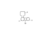
次に、他の実施例を、図5に示す。この実施例では、吸気管4,5をエアクリーナ8の下流側で連結管20で接続し、この接続部近傍の吸気管5の側部にレゾネータ9を備えている。また、図6に示すように、接続部近傍の吸気管5の上側にレゾネータ9を備えてもよい。さらに、図7に示すように、接続部近傍の吸気管4の上側にレゾネータ9を備えてもよい。
【0019】
さらに、他の実施例を、図8に示す。この実施例では、吸気管4,5をエアクリーナ8の下流側で連結管30で接続し、この接続する連結管30にレゾネータ9を備えている。
【0020】
このように、吸気管4,5を接続することで、接続部または接続部近傍にレゾネータ9を備えても、音圧レベルは吸気管4,5及び接続部または接続部近傍はほぼ同じになるため吸気騒音を低減できる。
【0021】
以上の実施例は、単気筒4サイクルエンジンで吸気管が2本接続されたものに対する実施例であり、この場合は各吸気管への入力、すなわち燃焼室で生じる吸気負圧は同位相であり、所定の位置における音圧のピークが現れるタイミングにずれがないため、それを考慮する必要はないが、この発明を吸気行程が同時でない多気筒エンジンの複数の吸気管に対し適用する際には入力に位相差があるため、上記タイミングのずれを考慮することで適用が可能となる。
【0022】
【発明の効果】
前記したように、請求項1記載の発明は、複数の吸気管を、エアクリーナの下流側で接続し、この接続部または接続部近傍にレゾネータを備え、複数の吸気管を連通させるから、逆位相となる共鳴周波数が小さい場合での吸気騒音レベルを低減すると共に、レゾネータにより共鳴周波数が大きい場合での吸気騒音レベルを低減することができ、しかも簡単な構造で、低コスト、小型である。また、単一のレゾネータでよくなり、レゾネータ効果のチューニングが簡単である。
【図面の簡単な説明】
【図1】吸気装置を備える単気筒4サイクルエンジンの側面図である。
【図2】レゾネータの配置を示す平面図である。
【図3】レゾネータの配置を示す側面図である。
【図4】レゾネータの側面図である。
【図5】吸気装置の他の実施例を示す図である。
【図6】吸気装置のさらに他の実施例を示す図である。
【図7】吸気装置のさらに他の実施例を示す図である。
【図8】吸気装置のさらに他の実施例を示す図である。
【図9】従来の複数の吸気管にエアクリーナを備える吸気装置を示す図である。
【図10】従来の複数の吸気管の内の1つの吸気管にレゾネータを備える吸気装置を示す図である。
【図11】従来の複数の吸気管のそれぞれにレゾネータを備える吸気装置を示す図である。
【符号の説明】
1 単気筒4サイクルエンジン
4,5 吸気管
8 エアクリーナ
9 レゾネータ[0001]
BACKGROUND OF THE INVENTION
The present invention relates to an intake device for an engine including a plurality of intake pipes.
[0002]
[Prior art]
For example, an intake system of a four-cycle single-cylinder engine includes a plurality of intake pipes, each of which is connected to an air cleaner. For example, as shown in FIG. 9A, it is conceivable to connect an
[0003]
[Problems to be solved by the invention]
For this reason, for example, as a countermeasure against an increase in the noise level when the resonance frequency f L2 is large, for example, as shown in FIG. 10A, it is conceivable to attach the
[0004]
Further, for example, as shown in FIG. 11 (a), it is conceivable to attach the
[0005]
The present invention has been made in view of such circumstances, and an object thereof is to provide an intake device for an engine that reduces intake noise, has a simple structure, is low-cost, and is small.
[0006]
[Means for Solving the Problems]
In order to solve the above problems and achieve the object, an invention according to
[0007]
In this way, by connecting a plurality of intake pipes, it is possible to reduce the intake noise level when the resonance frequency having the opposite phase is small, and to reduce the intake noise level when the resonance frequency is high by the resonator. It is simple and has a low cost and a small size. Also, a single resonator is sufficient, and tuning when replacing the resonator is easy.
[0008]
DETAILED DESCRIPTION OF THE INVENTION
Embodiments of an intake device for a four-cycle engine according to the present invention will be described below with reference to the drawings.
[0009]
First, the embodiment of FIGS. 1 to 4 will be described. 1 is a side view of a single-cylinder four-cycle engine provided with an intake device, FIG. 2 is a plan view showing the arrangement of resonators, FIG. 3 is a side view showing the arrangement of resonators, and FIG. 4 is a side view of the resonator.
[0010]
In the figure,
[0011]
As shown in FIG. 3, a
[0012]
The upper portion of the
[0013]
The
[0014]
Further, the
[0015]
In this way, by connecting the plurality of
[0016]
The
[0017]
The arrangement of the
[0018]
Next, another embodiment is shown in FIG. In this embodiment, the
[0019]
Furthermore, another embodiment is shown in FIG. In this embodiment, the
[0020]
In this way, by connecting the
[0021]
The above embodiment is an embodiment for a single cylinder four-cycle engine in which two intake pipes are connected. In this case, the input to each intake pipe, that is, the intake negative pressure generated in the combustion chamber is in phase. However, since there is no deviation in the timing at which the sound pressure peak appears at a predetermined position, it is not necessary to consider this. However, when the present invention is applied to a plurality of intake pipes of a multi-cylinder engine in which the intake stroke is not simultaneous, Since there is a phase difference in the input, application is possible by taking the timing deviation into consideration.
[0022]
【The invention's effect】
As described above, the invention according to
[Brief description of the drawings]
FIG. 1 is a side view of a single-cylinder four-cycle engine provided with an intake device.
FIG. 2 is a plan view showing the arrangement of resonators.
FIG. 3 is a side view showing the arrangement of resonators.
FIG. 4 is a side view of a resonator.
FIG. 5 is a view showing another embodiment of the intake device.
FIG. 6 is a view showing still another embodiment of the intake device.
FIG. 7 is a view showing still another embodiment of the intake device.
FIG. 8 is a view showing still another embodiment of the intake device.
FIG. 9 is a view showing an air intake device provided with an air cleaner in a plurality of conventional air intake pipes.
FIG. 10 is a view showing an intake device provided with a resonator in one intake pipe among a plurality of conventional intake pipes.
FIG. 11 is a view showing an intake device provided with a resonator in each of a plurality of conventional intake pipes.
[Explanation of symbols]
1
Claims (1)
Priority Applications (1)
| Application Number | Priority Date | Filing Date | Title |
|---|---|---|---|
| JP32880395A JP3685220B2 (en) | 1995-12-18 | 1995-12-18 | Engine intake system |
Applications Claiming Priority (1)
| Application Number | Priority Date | Filing Date | Title |
|---|---|---|---|
| JP32880395A JP3685220B2 (en) | 1995-12-18 | 1995-12-18 | Engine intake system |
Publications (2)
| Publication Number | Publication Date |
|---|---|
| JPH09170506A JPH09170506A (en) | 1997-06-30 |
| JP3685220B2 true JP3685220B2 (en) | 2005-08-17 |
Family
ID=18214281
Family Applications (1)
| Application Number | Title | Priority Date | Filing Date |
|---|---|---|---|
| JP32880395A Expired - Lifetime JP3685220B2 (en) | 1995-12-18 | 1995-12-18 | Engine intake system |
Country Status (1)
| Country | Link |
|---|---|
| JP (1) | JP3685220B2 (en) |
Cited By (1)
| Publication number | Priority date | Publication date | Assignee | Title |
|---|---|---|---|---|
| US10309355B2 (en) | 2016-03-30 | 2019-06-04 | Honda Motor Co., Ltd. | Saddle-ride type vehicle |
-
1995
- 1995-12-18 JP JP32880395A patent/JP3685220B2/en not_active Expired - Lifetime
Cited By (1)
| Publication number | Priority date | Publication date | Assignee | Title |
|---|---|---|---|---|
| US10309355B2 (en) | 2016-03-30 | 2019-06-04 | Honda Motor Co., Ltd. | Saddle-ride type vehicle |
Also Published As
| Publication number | Publication date |
|---|---|
| JPH09170506A (en) | 1997-06-30 |
Similar Documents
| Publication | Publication Date | Title |
|---|---|---|
| JPH10213027A (en) | Intake system of engine | |
| JPH0580588B2 (en) | ||
| JP3685220B2 (en) | Engine intake system | |
| JPH04209961A (en) | Intake device for internal combustion engine | |
| JP2897172B2 (en) | Noise reduction structure of air cleaner for internal combustion engine | |
| JP4019398B2 (en) | Engine intake system | |
| JP2516513Y2 (en) | Internal combustion engine intake system | |
| JPS6045772A (en) | Vibration damping duct | |
| JPH1018849A (en) | Intake device for internal combustion engine | |
| JP7106987B2 (en) | Intake manifold for internal combustion engine | |
| JPH0533704Y2 (en) | ||
| JPH081156B2 (en) | Engine intake system | |
| JP3149637B2 (en) | Intake device for internal combustion engine | |
| KR200156995Y1 (en) | Vibration-absorbing connection structure between air cleaner and throttle body | |
| JPH09291861A (en) | Intake system structure of v-type engine | |
| JPS5933849Y2 (en) | Engine intake system for motorcycles equipped with V-type engines | |
| EP1789660B1 (en) | An improved exhaust system of a single cylinder four stroke spark ignition engine | |
| KR0124052Y1 (en) | Surge tank for the intake manifold of an engine | |
| JPH0730910Y2 (en) | Intake device for V-type internal combustion engine | |
| JPH0333530Y2 (en) | ||
| JPH11200968A (en) | Intake system in slant type multicylindered internal combustion engine | |
| JP3525419B2 (en) | Intake device for supercharged engine | |
| JP2530900Y2 (en) | Support device for intake manifold | |
| JP2000145554A (en) | Inertia supercharged intake manifold for internal combustion engine | |
| JPH0210271Y2 (en) |
Legal Events
| Date | Code | Title | Description |
|---|---|---|---|
| TRDD | Decision of grant or rejection written | ||
| A01 | Written decision to grant a patent or to grant a registration (utility model) |
Free format text: JAPANESE INTERMEDIATE CODE: A01 Effective date: 20050524 |
|
| A61 | First payment of annual fees (during grant procedure) |
Free format text: JAPANESE INTERMEDIATE CODE: A61 Effective date: 20050524 |
|
| R150 | Certificate of patent (=grant) or registration of utility model |
Free format text: JAPANESE INTERMEDIATE CODE: R150 |
|
| FPAY | Renewal fee payment (prs date is renewal date of database) |
Free format text: PAYMENT UNTIL: 20110610 Year of fee payment: 6 |
|
| FPAY | Renewal fee payment (prs date is renewal date of database) |
Free format text: PAYMENT UNTIL: 20110610 Year of fee payment: 6 |
|
| FPAY | Renewal fee payment (prs date is renewal date of database) |
Free format text: PAYMENT UNTIL: 20120610 Year of fee payment: 7 |
|
| FPAY | Renewal fee payment (prs date is renewal date of database) |
Free format text: PAYMENT UNTIL: 20120610 Year of fee payment: 7 |
|
| FPAY | Renewal fee payment (prs date is renewal date of database) |
Free format text: PAYMENT UNTIL: 20130610 Year of fee payment: 8 |
|
| R250 | Receipt of annual fees |
Free format text: JAPANESE INTERMEDIATE CODE: R250 |
|
| R250 | Receipt of annual fees |
Free format text: JAPANESE INTERMEDIATE CODE: R250 |
|
| EXPY | Cancellation because of completion of term |