JP3635927B2 - Automatic engine stop / start device for vehicle - Google Patents
Automatic engine stop / start device for vehicle Download PDFInfo
- Publication number
- JP3635927B2 JP3635927B2 JP17341598A JP17341598A JP3635927B2 JP 3635927 B2 JP3635927 B2 JP 3635927B2 JP 17341598 A JP17341598 A JP 17341598A JP 17341598 A JP17341598 A JP 17341598A JP 3635927 B2 JP3635927 B2 JP 3635927B2
- Authority
- JP
- Japan
- Prior art keywords
- braking force
- engine
- vehicle
- start device
- stop
- Prior art date
- Legal status (The legal status is an assumption and is not a legal conclusion. Google has not performed a legal analysis and makes no representation as to the accuracy of the status listed.)
- Expired - Lifetime
Links
Images


Classifications
-
- B—PERFORMING OPERATIONS; TRANSPORTING
- B60—VEHICLES IN GENERAL
- B60W—CONJOINT CONTROL OF VEHICLE SUB-UNITS OF DIFFERENT TYPE OR DIFFERENT FUNCTION; CONTROL SYSTEMS SPECIALLY ADAPTED FOR HYBRID VEHICLES; ROAD VEHICLE DRIVE CONTROL SYSTEMS FOR PURPOSES NOT RELATED TO THE CONTROL OF A PARTICULAR SUB-UNIT
- B60W10/00—Conjoint control of vehicle sub-units of different type or different function
- B60W10/04—Conjoint control of vehicle sub-units of different type or different function including control of propulsion units
- B60W10/06—Conjoint control of vehicle sub-units of different type or different function including control of propulsion units including control of combustion engines
-
- B—PERFORMING OPERATIONS; TRANSPORTING
- B60—VEHICLES IN GENERAL
- B60W—CONJOINT CONTROL OF VEHICLE SUB-UNITS OF DIFFERENT TYPE OR DIFFERENT FUNCTION; CONTROL SYSTEMS SPECIALLY ADAPTED FOR HYBRID VEHICLES; ROAD VEHICLE DRIVE CONTROL SYSTEMS FOR PURPOSES NOT RELATED TO THE CONTROL OF A PARTICULAR SUB-UNIT
- B60W10/00—Conjoint control of vehicle sub-units of different type or different function
- B60W10/04—Conjoint control of vehicle sub-units of different type or different function including control of propulsion units
-
- B—PERFORMING OPERATIONS; TRANSPORTING
- B60—VEHICLES IN GENERAL
- B60W—CONJOINT CONTROL OF VEHICLE SUB-UNITS OF DIFFERENT TYPE OR DIFFERENT FUNCTION; CONTROL SYSTEMS SPECIALLY ADAPTED FOR HYBRID VEHICLES; ROAD VEHICLE DRIVE CONTROL SYSTEMS FOR PURPOSES NOT RELATED TO THE CONTROL OF A PARTICULAR SUB-UNIT
- B60W10/00—Conjoint control of vehicle sub-units of different type or different function
- B60W10/18—Conjoint control of vehicle sub-units of different type or different function including control of braking systems
-
- B—PERFORMING OPERATIONS; TRANSPORTING
- B60—VEHICLES IN GENERAL
- B60W—CONJOINT CONTROL OF VEHICLE SUB-UNITS OF DIFFERENT TYPE OR DIFFERENT FUNCTION; CONTROL SYSTEMS SPECIALLY ADAPTED FOR HYBRID VEHICLES; ROAD VEHICLE DRIVE CONTROL SYSTEMS FOR PURPOSES NOT RELATED TO THE CONTROL OF A PARTICULAR SUB-UNIT
- B60W30/00—Purposes of road vehicle drive control systems not related to the control of a particular sub-unit, e.g. of systems using conjoint control of vehicle sub-units
- B60W30/18—Propelling the vehicle
- B60W30/18009—Propelling the vehicle related to particular drive situations
- B60W30/18027—Drive off, accelerating from standstill
-
- B—PERFORMING OPERATIONS; TRANSPORTING
- B60—VEHICLES IN GENERAL
- B60W—CONJOINT CONTROL OF VEHICLE SUB-UNITS OF DIFFERENT TYPE OR DIFFERENT FUNCTION; CONTROL SYSTEMS SPECIALLY ADAPTED FOR HYBRID VEHICLES; ROAD VEHICLE DRIVE CONTROL SYSTEMS FOR PURPOSES NOT RELATED TO THE CONTROL OF A PARTICULAR SUB-UNIT
- B60W30/00—Purposes of road vehicle drive control systems not related to the control of a particular sub-unit, e.g. of systems using conjoint control of vehicle sub-units
- B60W30/18—Propelling the vehicle
- B60W30/1819—Propulsion control with control means using analogue circuits, relays or mechanical links
-
- F—MECHANICAL ENGINEERING; LIGHTING; HEATING; WEAPONS; BLASTING
- F02—COMBUSTION ENGINES; HOT-GAS OR COMBUSTION-PRODUCT ENGINE PLANTS
- F02D—CONTROLLING COMBUSTION ENGINES
- F02D11/00—Arrangements for, or adaptations to, non-automatic engine control initiation means, e.g. operator initiated
- F02D11/06—Arrangements for, or adaptations to, non-automatic engine control initiation means, e.g. operator initiated characterised by non-mechanical control linkages, e.g. fluid control linkages or by control linkages with power drive or assistance
- F02D11/10—Arrangements for, or adaptations to, non-automatic engine control initiation means, e.g. operator initiated characterised by non-mechanical control linkages, e.g. fluid control linkages or by control linkages with power drive or assistance of the electric type
- F02D11/105—Arrangements for, or adaptations to, non-automatic engine control initiation means, e.g. operator initiated characterised by non-mechanical control linkages, e.g. fluid control linkages or by control linkages with power drive or assistance of the electric type characterised by the function converting demand to actuation, e.g. a map indicating relations between an accelerator pedal position and throttle valve opening or target engine torque
-
- F—MECHANICAL ENGINEERING; LIGHTING; HEATING; WEAPONS; BLASTING
- F02—COMBUSTION ENGINES; HOT-GAS OR COMBUSTION-PRODUCT ENGINE PLANTS
- F02D—CONTROLLING COMBUSTION ENGINES
- F02D41/00—Electrical control of supply of combustible mixture or its constituents
- F02D41/30—Controlling fuel injection
- F02D41/38—Controlling fuel injection of the high pressure type
- F02D41/40—Controlling fuel injection of the high pressure type with means for controlling injection timing or duration
- F02D41/406—Electrically controlling a diesel injection pump
- F02D41/408—Electrically controlling a diesel injection pump of the distributing type
-
- F—MECHANICAL ENGINEERING; LIGHTING; HEATING; WEAPONS; BLASTING
- F02—COMBUSTION ENGINES; HOT-GAS OR COMBUSTION-PRODUCT ENGINE PLANTS
- F02N—STARTING OF COMBUSTION ENGINES; STARTING AIDS FOR SUCH ENGINES, NOT OTHERWISE PROVIDED FOR
- F02N11/00—Starting of engines by means of electric motors
- F02N11/08—Circuits specially adapted for starting of engines
- F02N11/0814—Circuits specially adapted for starting of engines comprising means for controlling automatic idle-start-stop
- F02N11/0818—Conditions for starting or stopping the engine or for deactivating the idle-start-stop mode
-
- B—PERFORMING OPERATIONS; TRANSPORTING
- B60—VEHICLES IN GENERAL
- B60W—CONJOINT CONTROL OF VEHICLE SUB-UNITS OF DIFFERENT TYPE OR DIFFERENT FUNCTION; CONTROL SYSTEMS SPECIALLY ADAPTED FOR HYBRID VEHICLES; ROAD VEHICLE DRIVE CONTROL SYSTEMS FOR PURPOSES NOT RELATED TO THE CONTROL OF A PARTICULAR SUB-UNIT
- B60W2540/00—Input parameters relating to occupants
- B60W2540/12—Brake pedal position
-
- B—PERFORMING OPERATIONS; TRANSPORTING
- B60—VEHICLES IN GENERAL
- B60W—CONJOINT CONTROL OF VEHICLE SUB-UNITS OF DIFFERENT TYPE OR DIFFERENT FUNCTION; CONTROL SYSTEMS SPECIALLY ADAPTED FOR HYBRID VEHICLES; ROAD VEHICLE DRIVE CONTROL SYSTEMS FOR PURPOSES NOT RELATED TO THE CONTROL OF A PARTICULAR SUB-UNIT
- B60W30/00—Purposes of road vehicle drive control systems not related to the control of a particular sub-unit, e.g. of systems using conjoint control of vehicle sub-units
- B60W30/18—Propelling the vehicle
- B60W30/18009—Propelling the vehicle related to particular drive situations
- B60W30/18109—Braking
- B60W30/18118—Hill holding
-
- F—MECHANICAL ENGINEERING; LIGHTING; HEATING; WEAPONS; BLASTING
- F02—COMBUSTION ENGINES; HOT-GAS OR COMBUSTION-PRODUCT ENGINE PLANTS
- F02N—STARTING OF COMBUSTION ENGINES; STARTING AIDS FOR SUCH ENGINES, NOT OTHERWISE PROVIDED FOR
- F02N2200/00—Parameters used for control of starting apparatus
- F02N2200/10—Parameters used for control of starting apparatus said parameters being related to driver demands or status
- F02N2200/102—Brake pedal position
-
- F—MECHANICAL ENGINEERING; LIGHTING; HEATING; WEAPONS; BLASTING
- F02—COMBUSTION ENGINES; HOT-GAS OR COMBUSTION-PRODUCT ENGINE PLANTS
- F02N—STARTING OF COMBUSTION ENGINES; STARTING AIDS FOR SUCH ENGINES, NOT OTHERWISE PROVIDED FOR
- F02N2200/00—Parameters used for control of starting apparatus
- F02N2200/12—Parameters used for control of starting apparatus said parameters being related to the vehicle exterior
- F02N2200/124—Information about road conditions, e.g. road inclination or surface
-
- Y—GENERAL TAGGING OF NEW TECHNOLOGICAL DEVELOPMENTS; GENERAL TAGGING OF CROSS-SECTIONAL TECHNOLOGIES SPANNING OVER SEVERAL SECTIONS OF THE IPC; TECHNICAL SUBJECTS COVERED BY FORMER USPC CROSS-REFERENCE ART COLLECTIONS [XRACs] AND DIGESTS
- Y02—TECHNOLOGIES OR APPLICATIONS FOR MITIGATION OR ADAPTATION AGAINST CLIMATE CHANGE
- Y02T—CLIMATE CHANGE MITIGATION TECHNOLOGIES RELATED TO TRANSPORTATION
- Y02T10/00—Road transport of goods or passengers
- Y02T10/10—Internal combustion engine [ICE] based vehicles
- Y02T10/40—Engine management systems
Landscapes
- Engineering & Computer Science (AREA)
- Chemical & Material Sciences (AREA)
- Combustion & Propulsion (AREA)
- Mechanical Engineering (AREA)
- Transportation (AREA)
- General Engineering & Computer Science (AREA)
- Automation & Control Theory (AREA)
- Regulating Braking Force (AREA)
- Control Of Vehicle Engines Or Engines For Specific Uses (AREA)
- Output Control And Ontrol Of Special Type Engine (AREA)
- Control Of Driving Devices And Active Controlling Of Vehicle (AREA)
Description
【0001】
【発明の属する技術分野】
この発明は車両におけるエンジン自動停止・始動装置に関するものである。
【0002】
【従来の技術】
従来、市街地走行時に、交差点で自動車が停車した場合、所定の停止条件下でエンジンを自動停止させ、その後、所定の始動条件下でエンジンを再始動させることにより、燃料を節約したり、排気エミッションを向上させるエンジン自動停止・始動装置(アイドルストップ装置)が知られている。
【0003】
そして、特開平9−209790号公報に記載のエンジン自動停止・始動装置においては、アクセルがオン操作される前におけるブレーキの解除によりエンジンを停止状態から再始動するようにしている。
【0004】
ところが、ブレーキ解除した後のアクセルをオン操作した時に十分なエンジン出力が得られないことがあり、エンジン再始動の動作開始からアクセルペダルの踏み込みまでに発進のためのエンジン出力を得るようにしたい。特に、トルクコンバータ付自動変速機を備えた車両においてシフトレバーが走行位置にある時にアクセルペダルを踏み込まなくても車両がゆっくり動く、いわゆるクリープ現象を利用した走行を行うことが困難な場合がある。
【0005】
【発明が解決しようとする課題】
そこで、この発明の目的は、より円滑にブレーキ解除からエンジン駆動状態に移行させることができる車両におけるエンジン自動停止・始動装置を提供することにある。
【0006】
【課題を解決するための手段】
請求項1に記載の車両におけるエンジン自動停止・始動装置は、トルクコンバータ付自動変速機を備え、シフトレバーの操作によって自動変速機の運転モードが切り替えられる車両におけるエンジン自動停止・始動装置であって、制動力操作部材の操作に伴うエンジン停止後において、シフトレバーが走行位置にあるとき、前記制動力操作部材による制動力の緩和から制動力操作部材を離すまでの間においてエンジンを再始動するエンジン制御手段を設け、少なくとも前記エンジンの停止中において車両が移動しないように所定の制動力を加える制動力制御手段を設けたことを特徴としている。
【0007】
よって、エンジン制御手段は、制動力操作部材による制動力の緩和から制動力操作部材を離すまでの間においてエンジンを再始動する。
その結果、早期にエンジンが始動され、ブレーキ解除した後にアクセルをオン操作した時に十分なエンジン出力が得られる。トルクコンバータ付自動変速機を備えた車両においてシフトレバーが走行位置にある時にアクセルペダルを踏み込まなくても車両がゆっくり動く、いわゆるクリープ現象を利用した走行を行うことができる。
また、少なくとも前記エンジンの停止中において車両が移動しないように所定の制動力を加える制動力制御手段を設けているため、実用上好ましいものとなる。
【0008】
ここで、請求項2に記載のように、前記エンジン制御手段は、制動力が所定の値より小さくなるとエンジンを再始動するものとすると、実用上好ましいものとなる。
【0009】
また、請求項3に記載のように、前記エンジン制御手段は、制動力が所定の値より大きくなるとエンジンを停止するとともに、制動力が所定の値より小さくなるとエンジンを再始動するものとすると、実用上好ましいものとなる。
【0010】
また、請求項4に記載のように、前記エンジン制御手段は、車両が移動しないだけの制動力が加わるとエンジンを停止するとともに、車両が移動しないだけの制動力より小さくなるとエンジンを再始動するものとすると、実用上好ましいものとなる。
【0011】
また、請求項5に記載のように、前記エンジン制御手段は、路面傾斜検出手段による路面の傾斜に応じて前記車両が移動しないだけの制動力を決定するものとすると、実用上好ましいものとなる。
【0012】
また、請求項6に記載のように、前記制動力操作部材による制動力の緩和から制動力操作部材を離すまでの操作を、ブレーキ油圧検出手段によるブレーキの油圧回路中の油圧にて検知するようにすると、実用上好ましいものとなる。
【0013】
また、請求項7に記載のように、前記制動力操作部材による制動力の緩和から制動力操作部材を離すまでの操作を、操作量検出手段による制動力操作部材の操作量にて検知するようにすると、実用上好ましいものとなる。
【0014】
また、請求項8に記載のように、前記操作量検出手段は、所定の操作位置でスイッチング信号を出力するスイッチであるとすると、実用上好ましいものとなる。
【0015】
また、請求項9に記載のように、前記制動力操作部材による制動力の緩和から制動力操作部材を離すまでの操作を、操作方向検出手段による制動力操作部材の操作方向にて検知するものとすると、実用上好ましいものとなる。
【0017】
ここで、請求項10に記載のように、前記制動力制御手段は、マスタシリンダからホイールシリンダへの油圧回路途中に設けられた電磁弁を制御することにより、車両が移動しないように所定の制動力を加えるものとすると、実用上好ましいものとなる。
【0018】
また、請求項11に記載のように、前記制動力制御手段は、エンジン回転数が所定値以上であると、所定の制動力の解除を行うものとすると、実用上好ましいものとなる。
【0019】
また、請求項12に記載のように、前記制動力制御手段は、エンジン回転数が所定値以上で、かつ、アクセルペダルの踏み込みがあると、所定の制動力の解除を行うものとすると、実用上好ましいものとなる。
【0020】
また、請求項13に記載のように、前記制動力制御手段は、路面傾斜検出手段による路面の傾斜が所定値以下のときに制動力の付与を禁止するものとすると、実用上好ましいものとなる。
【0021】
また、請求項14に記載のように、前記制動力制御手段は、エンジン始動後の一定回転領域になると所定の制動力の解除を行うものとすると、実用上好ましいものとなる。つまり、エンジン始動の際にエンジン吹き上がり後のアイドル回転数になった時に、ブレーキを解除すると、エンジン始動直後の吹き上がりによる不具合を回避(例えば、吹き上がりによる車両の飛び出しを未然に防止する)ことができる。
【0022】
また、請求項15に記載のように、前記制動力制御手段は、制動力操作部材による制動力が所定値以下になったときにおいて、他の手段による制動力が所定値以上ならば、制動力の付与を禁止するものとすると、実用上好ましいものとなる。
【0023】
また、請求項16に記載のように、前記制動力制御手段は、前記電磁弁のコイル温度が所定値に達する、あるいは、電磁弁の作動開始からの時間が所定値に達すると、電磁弁のコイル通電を終了するとともにエンジンを再始動するものとすると、実用上好ましいものとなる。
【0024】
また、請求項17に記載のように、複数の制動力操作部材ごとにその制動力を保持するための手段を備え、前記制動力制御手段は、複数の制動力操作部材による各制動力の和が所定値以下になったときに制動力の付与を開始するものとすると、実用上好ましいものとなる。
【0025】
【発明の実施の形態】
(第1の実施の形態)
以下、この発明を具体化した実施の形態を図面に従って説明する。
【0026】
はじめに、図1を参照して、エンジン自動停止・始動装置が適用されるエンジン、並びにその周辺装置の概略構成について説明する。
車体(図示せず)にはエンジン1が搭載され、エンジン1は4サイクルガソリンエンジンを用いている。
【0027】
エンジン1にはインジェクタ(燃料噴射弁)2が装着されるとともに、イグナイタ3が接続されている。エンジン制御用の電子制御ユニット(ECU)4は、吸入空気量とエンジン回転速度およびエンジン冷却水温などの信号からエンジン1に最適な空燃比となるように燃料噴射量を算出し、各気筒の吸気管に設けられているインジェクタ2から適切な燃料量を噴射させる。また、エンジン制御用ECU4は、エンジンの回転速度と負荷の状態を示す信号から最適な点火時期となるようイグナイタ3を制御する。
【0028】
一方、エンジン1の出力軸には自動変速機5が連結されている。この自動変速機5は、エンジン1の出力を伝達するトルクコンバータ6と、このトルクコンバータ6によって駆動される変速機構7と、車体速やエンジン1の出力に応じて変速機構7の変速比を切り替える油圧回路(図示せず)とから構成されている。この自動変速機5は、運転席に設けられたシフトレバー(図示せず)の操作によって運転モードがP(パーキング)、R(後進)、N(ニュートラル)、D(ドライブ)、3速、2速、1速の各レンジに切り替えられる。そして、その時の運転状態に最適な変速となるように自動変速機5内の油圧回路が切り替えられる。
【0029】
自動変速機5の出力がディファレンシャルギア8に伝達され、駆動輪9が回転駆動される。
また、この車両には、エンジン自動停止・始動用(アイドルストップ用)の電子制御ユニット(ECU)10が搭載されている。ECU10はマイクロコンピュータを中心にして構成され、入力回路および出力回路を具備している。
【0030】
ECU10にはエンジン回転数センサ11、車速センサ12、アイドルスイッチ13、シフトポジションスイッチ14と接続され、ECU10はこれらのセンサからの信号によりエンジン回転数、車速、アクセルペダルが離されたか否か、自動変速機5のシフトレバーの位置を検知することができるようになっている。さらに、ECU10にはブレーキペダル操作量センサ15が接続されている。このブレーキペダル操作量センサ15は、図2に示すように、ブレーキペダル20の操作量θを電気信号に変換するセンサである。ここで、図2において、図中のA位置が踏み込み操作が無いときのペダル位置であり、D位置がブレーキペダル20の最大踏み込み位置である。
【0031】
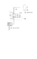
図1において、ECU10には路面傾斜センサ16が接続され、この路面傾斜センサ16により路面の傾斜角度が検出される。路面傾斜センサ16の構成例としては、例えば、図3に示すように、垂下した重り21に可動接点22を連結し、この可動接点22を円形の抵抗体23に摺動できるようにし、抵抗体23の両端に所定電圧を印加し、可動接点22での接触部における抵抗体23の分圧を測定し出力する構造を挙げることができる。
【0032】
図1において、ECU10はエンジン制御用ECU4に燃料カット信号と点火カット信号を送出することができ、この信号の送出にてエンジン1が停止するようになっている。また、ECU10はエンジン制御用ECU4に燃料噴射信号と点火信号を送出することができ、この信号の送出にてエンジン1の燃料噴射動作と点火動作が行われるようになっている。さらに、ECU10にはスタータ(モータ)17が接続され、ECU10はスタータ17を駆動制御する。
【0033】
次に、このように構成した車両におけるエンジン自動停止・始動装置の作用を説明する。
図4,5に、エンジン自動停止および自動再始動処理のフローチャートを示す。また、図6にはタイミングチャートを示す。図6において、ブレーキペダルの操作量、エンジン回転数、車速、エンジン・カット信号(燃料カット信号,点火カット信号)、エンジン・オン信号(エンジン点火信号,燃料噴射信号)、スタータ、アイドルスイッチの状態を示す。この図6においては、t1のタイミングにてブレーキペダル20の踏み込み操作を開始してt3にて最大まで踏み込み、このペダル踏み込みにより車両を停止させ、その後のt4のタイミングにてブレーキペダル20の踏み込みを緩め出しt7にてブレーキペダル20から足を離すことにより発進可能とし、t8のタイミングにてアクセルペダルの踏み込みを開始して車両を走行させたものとしている。
【0034】
ECU10は、図4のステップ101〜106でエンジン停止条件が成立したか否かを判断する。具体的には、ステップ101においては、エンジン回転数がアイドル回転数以下か判断し、ステップ102においては車速が「0」か否か判断する。また、ステップ103においては、アクセルペダルが操作されずにアイドルスイッチがオンか否か判断する。
【0035】
さらに、ステップ104においては、ブレーキペダル20の操作による制動力が路面傾斜角αに応じた車両の移動を阻止する制動力以上か否か判断する。より具体的には、ECU10は、路面傾斜センサ16による路面傾斜角αから、図7に示すマップを用いて路面傾斜角αに対応する必要制動力(即ち、ペダル踏み込み量)Fを求め、この算出値に所定のマージン量を加え、この踏み込み量以上にペダルの踏み込み操作が行われたか否か判断する。図7に示すマップの特性線L1は、路面傾斜角αに応じた車両の移動を阻止する制動力を予め求めておいたものである。つまり、図2のA位置からブレーキペダル20を踏み込んでいくと、車両の転がりを防止できる踏み込み位置Bに達し、さらに踏み込んだ位置Cを、センシング位置としており、ペダル踏み込み量がC位置よりも踏み込まれると確実に車両の転がりを防止できる。
【0036】
このようにして、ブレーキペダル20が車両の転がりを防止できる踏み込み位置Bより踏み込んだ位置Cを越えて、さらに踏み込んだ状態にあるときに(ブレーキペダルが図2の領域Z3にあるとき)、図4のステップ104がYESとなる。換言すると、車両の転がりを防止できる踏み込み位置(図2の位置B)は、路面の傾斜角に応じて変化するが、路面傾斜センサ16により検出された路面の傾斜から車両の転がり防止踏み込み量がECU10により算出される。
【0037】
また、図4のステップ105においては、シフトレバーが「D(ドライブ位置)」,「2速」,「1速」であるか判断する。さらに、ステップ106においては、他の禁止条件(エンジン冷却水温が所定温度領域内にあり、かつ、充電系に異常がなく、かつ、バッテリ状態が良好である等)を満足するか否か判定する。
【0038】
そして、ECU10は、これらの条件が全て成立してエンジン停止条件を満足すると(図6のt2のタイミング)、図4のステップ107に移行してエンジンの燃料カット信号および点火カット信号をエンジン制御用ECU4に送出し、エンジン1を自動停止させる。
【0039】
そして、ECU10は、エンジン1の停止処理終了後において、図5のエンジン始動処理に移行する。
図5において、ECU10はステップ201〜203でエンジン1の始動条件が成立したか否か判断する。具体的には、ステップ201においてはエンジン回転数が所定値より小さくエンジンがストール状態か判断する。また、ステップ202においてはシフトレバーが「D(ドライブ位置)」,「2速」,「1速」であるか判断する。さらに、ステップ203においては、ブレーキペダル20を緩めていき制動力が路面傾斜角αに応じた車両の移動を阻止する制動力以下となったか否か判断する。より具体的には、ECU10は、路面傾斜センサ16による路面傾斜角αから、図7に示すマップを用いて路面傾斜角αに対応する必要制動力(即ち、ペダル踏み込み量)Fを求め、この算出値にマージン量を加え、この踏み込み量以下にペダルの踏み込み操作が行われたか否か判断する。つまり、エンジ停止の判定に用いた図2のC位置よりも緩められてペダル操作領域Z2に入ったか否か判定する。
【0040】
そして、ECU10は、これらの条件が全て成立してエンジン1の始動条件が成立すると(図6のt5のタイミング)、図5のステップ204に移行してエンジンを再始動すべくエンジン制御ECU4にオン信号(エンジン1の点火信号および燃料噴射信号)を送出し、燃料噴射および点火を開始させる。また、ECU10は、ステップ205でスタータ17を通電しエンジン1を始動する。
【0041】
その後、ECU10はステップ206でエンジン回転数neがエンジンの着火回転数ne0を越えると(図6のt6のタイミング)、エンジンが完爆したとしてステップ207にてスタータ17の通電を中止してスタータ17を停止する。
【0042】
このように、エンジン停止後において、ブレーキペダル20が図2の領域Z2、即ち、ブレーキペダル20による制動力の緩和からブレーキペダル20を離すまでの間においてエンジン1を再始動するようにしたので、エンジン始動に関わるタイムラグが少なくスムーズな発進が可能になる。また、AT車におけるクリープ力を利用した微速走行が可能となる。さらに、坂道発進の際に、両の後ずさりせずに発進ことができる。
【0043】
より詳しくは、車速が「0」、アクセル・オフ、バッテリ状態が良好、等のエンジン自動停止条件を満足し、かつ車両の制動力が所定値以上であるとき、つまり車両の転がりを防ぐのに十分な制動力を確保できるときにエンジンが自動停止されるとともに、エンジン停止状態で制動力が所定値以下になったとき、つまり、車両の転がりを防ぐ制動力を確保しつつも制動力が少し弱まったときエンジンが自動再始動される。従って、車両の転がりを防ぐ制動力を確保した状態でエンジンの自動再始動を開始するので、平坦路のみならず坂道での発進においても後ずさりすることなく発進できる。
【0044】
このように本実施形態は、下記の特徴を有する。
(イ)エンジン制御手段としてのECU10は、制動力操作部材としてのブレーキペダル20による制動力の緩和からブレーキペダル20を離すまでの間においてエンジン1を再始動するので、早期にエンジンが始動され、ブレーキ解除した後にアクセルをオン操作した時に十分なエンジン出力が得られる。特に、トルクコンバータ付自動変速機5を備えた車両においてシフトレバーが走行位置にある時にアクセルペダル20を踏み込まなくても車両がゆっくり動く、いわゆるクリープ現象を利用した走行を行うことができる。
(ロ)路面傾斜検出手段としての路面傾斜センサ16を用いて路面傾斜に応じて車両が移動しないだけの制動力を決定するようにしたので、傾斜が大きいほど必要となる制動力も大きく設定されるので、確実に車両の後ずさりを防止できる。
(ハ)操作量検出手段としてプレーキペダル操作量センサ15を用いたので、制動状態を簡単な構成で検出できる。
【0045】
本例の応用例としては、ブレーキペダル20の位置(操作量)を連続的に測定するリニア式操作量センサ15を用いたが、図8に信号波形SG1で示すように、ブレーキペダル20の所定の踏み込み位置でオン/オフするスイッチで代用してもよい。このように、ブレーキペダル20の所定の踏み込み位置でスイッチング信号を出力する(ON/OFFする)スイッチを設け、これにより制動力を検出する構成とすることにより、より簡素な構造となりコストダウンを図ることができる。
【0046】
また、ブレーキペダル20の操作量を検出するのではなく、直接ブレーキ圧を測定してもよい。つまり、ブレーキペダル操作量センサ15の代わりに、ブレーキ圧を検出する油圧センサを用いてもよい。このように、ブレーキ圧を検出して車両の制動力とすることで、制動状態を的確に検出できる。
【0047】
また、ブレーキペダル20の位置(操作量)θを連続的に測定するリニア式操作量センサ15を用い、図9に示すように、ペダル操作方向を検知すべくブレーキペダル20の操作速度θ’の正負を求め、ブレーキペダル20の操作速度が負になると(図9のt4のタイミング)、エンジンの再始動を行うようにしてもよい。このように、ブレーキペダル20の操作速度θ’を検出することで、制動状態を簡単な構成で検出でき、ドライバの意思を的確に検出できる。
【0048】
また、制動力としてフットブレーキの制動力を用いた構成を示したが、例えばパーキングブレーキ(駐車ブレーキ)の制動力を用いた構成としてもよい。
(第2の実施の形態)
次に、第2の実施の形態を、第1の実施の形態との相違点を中心に説明する。
【0049】
図10に示すように、ブレーキペダル20がマスタシリンダ30と連動するとともに、マスタシリンダ30とホイールシリンダ31が油圧管路29にて連結され、マスタシリンダ30で発生した油圧がホイールシリンダ31に伝わり車輪が制動される。ここで、本実施形態においては、ブレーキペダル20とマスタシリンダ30との間の油圧管路29の途中(油圧回路中)には電磁弁32が設けられている。この電磁弁32は常開式の開閉弁であって、コイル32aの通電にて油圧回路を閉路してホイールシリンダ31でのブレーキ油圧が保持される。そして、ブレーキペダル20を踏み込んでいるときに電磁弁32のコイル32aを通電(励磁)することにより、ブレーキペダル20を離してもブレーキ力が保持される。このブレーキ力の保持動作、即ち、電磁弁32の制御は、図1に示すようにECU10にて実行される。
【0050】
次に、このように構成した車両におけるエンジン自動停止・始動装置の作用を説明する。
図4と同様のエンジン自動停止処理によるエンジンの停止後において、エンジン始動処理に移行する。図11にエンジン自動再始動のフローチャートを示す。また、図12にはタイミングチャートを示す。
【0051】
ECU10は、図11のステップ301〜303でエンジンの始動条件が満足されると、ステップ304で電磁弁32を駆動して制動状態を保持する(図12のt10のタイミング)。つまり、ブレーキペダル20は車両の転がりを防止できる踏み込み状態であるので、そのブレーキ圧を保持することで車両の停止状態を維持できる。
【0052】
そして、ECU10は、ステップ305でエンジンの燃料噴射および点火を開始するとともに、ステップ306でスタータ17に通電しエンジンを始動する。ECU10は、ステップ307にてエンジン回転数neがエンジンの着火回転数ne0(例えば300rpm)を越えたら(図12のt11のタイミング)、エンジンが完爆したと判定しステップ308にてスタータ17の通電を中止してスタータ17を停止する。そして、ECU10は、ステップ309にてエンジン回転数neが車両を駆動するのに十分な回転数ne1(例えば400rpm)を越えたら(図12のt12のタイミング)、ステップ310に移行してステップ304において保持したブレーキ圧を解除する。
【0053】
なお、スタータ17の出力が大きく、エンジン始動時のクランキング回転数が高い時、つまり、ne1<ne0と考えられる場合には、エンジンスタータ17のオフの判定(図11のステップ307,308)とブレーキ圧保持解除の判定(図11のステップ309,310)との順序を入れ換える。
【0054】
以上の構成により、エンジン自動停止・始動装置を備えた車両の坂道発進において、ドライバの操作に関わらず車両が後ずさりせずに発進することが可能となる。
【0055】
つまり、坂道からの発進時にドライバが傾斜量を誤認し、エンジン始動中において傾斜量に対してドライバによるブレーキ操作力(制動力)が弱い場合、車両が後ずさりを起こす可能性があるが、ドライバの操作に関わらず車両の制動を制御できる電磁弁32を設け、エンジン停止状態でドライバ操作による制動力が所定値以下になったときにその制動力を保持するとともにエンジンを自動再始動し、さらにエンジン始動後における車両を前進させる駆動力(クリープ力)を発生させた後に車両の制動を解除することにより、確実に車両の後ずさりを防止できる。
【0056】
なお、制動力制御手段としてECU10および電磁弁32を用いたが、自ら制動力を発生するものとしてもよい。上述した例で電磁弁32を用いたのは、ブレーキ操作開始時には常にドライバによって車両の制動力が確保されていることに着目したものであり、この場合には、ブレーキの油圧回路中に配置した電磁弁32を閉弁することでブレーキ圧を維持して車両の制動が保持できるとともに、エンジン再始動後に電磁弁32を開弁することで車両を制動するブレーキ圧を解放でき、新たな動力源を持つことなく制動力を制御でき簡素な構造で構成できる。
【0057】
このように本実施形態は、下記の特徴を有する。
(イ)少なくともエンジンの停止中において車両が移動しないように所定の制動力を加える制動力制御手段(ECU10および電磁弁32)を設けたので、ドライバのブレーキ操作に関わらず車両の移動なしに発進することが可能となる。
【0058】
このとき、マスタシリンダ30からホイールシリンダ31の油圧回路途中に電磁弁13を配置することにより実用上好ましいものとなり、さらに、エンジン回転数が所定値以上であると所定の制動力の解除を行うようにしたので、実用上好ましいものとなる。
(第3の実施の形態)
次に、第3の実施の形態を、第2の実施の形態との相違点を中心に説明する。
【0059】
図4と同様のエンジン自動停止処理によるエンジンの停止後において、エンジン始動処理に移行する。図13にエンジン自動再始動のフローチャートを示す。また、図14にはタイミングチャートを示す。本実施形態では、図11のステップ309と310の間に図13のステップ410を挿入してブレーキ圧解除の条件をもう一つ追加したものである。
【0060】
詳しくは、ECU10は、ステップ401〜403でエンジンの始動条件が満足されると(図14のt10のタイミング)、ステップ404でブレーキ圧を保持し、ステップ405でエンジンの燃料噴射および点火を開始するとともにステップ406でスタータ17に通電しエンジンを始動する。ECU10は、ステップ407にてエンジン回転数neがエンジンの着火回転数ne0を越えたら(図14のt11のタイミング)、エンジンが完爆したと判定しステップ408にてスタータ17の通電を中止してスタータ17を停止する。
【0061】
そして、ECU10は、ステップ409にてエンジン回転数neが車両を駆動するのに十分な回転数ne1を越え(図14のt12のタイミング)、さらにステップ410にてアクセルの踏み込みを検出したら(図14のt20のタイミング)、ステップ411に移行してステップ404において保持したブレーキ圧を解除する。
【0062】
従って、エンジンの停止から再始動の過程において、ドライバの操作に関わらず車両が後ずさりすることがないだけでなく、ブレーキを離しただけでは車両が動き出すことがない。
【0063】
以上の構成により、エンジン自動停止・始動装置を備えた車両の坂道発進において、ドライバの操作に関わらず車両が後ずさりせずに発進することが可能となるだけでなく、エンジンの始動とアクセルの踏み込みを検出しなければ制動を解除しないので、エンジン始動とともに車両が動き出すことがなく、ドライバの発進の意思を確実に反映できてより安全性が高まる。
【0064】
このように本実施形態は、下記の特徴を有する。
(イ)エンジン回転数が上昇し、かつアクセルの踏み込みを検出して制動力を解除するので、ブレーキを離してエンジンが始動しても車両が動き出すことがなく、アクセルの踏み込みというドライバの発進の意思を確実に反映できる。
(第4の実施の形態)
次に、第4の実施の形態を、第3の実施の形態との相違点を中心に説明する。
【0065】
図4と同様のエンジン自動停止処理によるエンジンの停止後において、エンジン始動処理に移行する。図15にエンジン自動再始動のフローチャートを示す。
本実施の形態においては、図15のステップ501で路面の傾斜角が所定値以下ならばステップ404のブレーキ圧保持のための処理を迂回し、路面の傾斜角が所定値以上であるときにのみブレーキ圧保持のための処理を実行する。
【0066】
つまり、第2,3の実施の形態においては、車両の停車位置が平坦路、傾斜路の区別なくエンジン自動停止中に車両の制動力を維持することになるのに対し、本実施形態では、路面の傾斜状態を検出して路面の傾斜角が所定値以上であるときにのみ車両を制動制御して、平坦路での停車等で電磁弁32のコイル通電のための電力消費を回避している。つまり、路面の傾斜角が所定値以下のときに制動力の付与を禁止して電力消費量を抑えている。
(第5の実施の形態)
次に、第5の実施の形態を、第3の実施の形態との相違点を中心に説明する。
【0067】
図4と同様のエンジン自動停止処理によるエンジンの停止後において、エンジン始動処理に移行する。図16にエンジン自動再始動のフローチャートを示す。また、図17にはタイミングチャートを示す。
【0068】
ECU10は、図16のステップ401〜403においてエンジン始動条件が成立し、ステップ404でブレーキ圧を保持しステップ405〜408でクランキングを行った後に、ステップ601でエンジン回転数が所定期間一定で、かつエンジン回転数がアイドル回転数であれば(図17のt30のタイミング)、ステップ411で所定の制動力の解除を行う。
【0069】
つまり、エンジン始動の際にエンジン吹き上がり後のアイドル回転数になった時にブレーキを解除するので、エンジン始動直後の吹き上がりによる車両の飛び出しを未然に防止することができる。
(第6の実施の形態)
次に、第6の実施の形態を、第2の実施の形態との相違点を中心に説明する。
【0070】
図18には本例のタイミングチャートを示す。本実施形態はパーキングブレーキの操作状態をも考慮した構成としている。
詳しくは、ドライバがエンジン停止中にパーキングブレーキを作動するとともにフットブレーキ(ブレーキペダル)を解除して停車状態を保持する場合、発車までのブレーキ保持時間が長くなり、コイルの発熱が懸念される。
【0071】
そこで、本実施形態では、以下の構成を採用している。
図1に示すように、ECU10に対しパーキングブレーキ操作量センサ40を接続している。このパーキングブレーキ操作量センサ40によりパーキングブレーキの操作量が検出される。
【0072】
そして、図18のタイミングチャートにおけるt40のタイミングにてエンジン再始動条件が満たされた時にパーキングブレーキの作動状態をモニタし、パーキングブレーキが作動状態であればブレーキ力の保持を行わないようにしている。
【0073】
つまり、図12においてエンジン停止中にパーキングブレーキを作動するとともにブレーキペダル20を解除して停車状態を保持すると、図19に示すように、ブレーキペダル20を緩める途中のt40においてブレーキペダル20によるブレーキ力が所定値を下回ると直ちにブレーキ圧の保持が行われることになる。これに対し、図18の本実施形態では、同じt40のタイミングにおいてパーキングブレーキが引かれているとブレーキ圧保持信号は出力されず長時間にわたる電磁弁32のコイル通電に伴う発熱を回避することができる。
【0074】
このように本実施形態は、下記の特徴を有する。
(イ)ECU10は、ブレーキペダル20による制動力が所定値以下になったときにおいて、他の手段(パーキングブレーキ)による制動力が所定値以上ならば、制動力の付与を禁止するので、電磁弁32のコイル発熱を抑制することができる。
(第7の実施の形態)
次に、第7の実施の形態を、第6の実施の形態との相違点を中心に説明する。
【0075】
図20には本例のタイミングチャートを示す。本実施形態は、第6の実施の形態でのエンジン停止時間が短くなるのを回避する工夫をしている。
詳しくは、第6の実施の形態においては、図21に示すように、ブレーキペダル20を緩める途中のt50においてブレーキペダル20によるブレーキ力が所定値を下回った時にエンジンが再始動することになる。これに対し以下の構成を採用してエンジン停止時間が短くなるのを回避する。
【0076】
図10の電磁弁32のコイル32aの温度をモニタするためのコイル温度センサ50(図1参照)を用いている。そして、ブレーキペダル20を緩める途中の図20のt50のタイミングにおいてパーキングブレーキが引かれていないと、電磁弁32を駆動し、その後、コイル32aの通電によりコイル温度が所定の温度T1に達すると(図19のt51のタイミング)、エンジンの始動を開始する。そして、t52にてスタータ17をオフした後、t53にてエンジン回転数が車両を駆動するに十分な回転数ne1になったとき電磁弁32をオフしてブレーキ力を開放する。その結果、図20のt50〜t51の期間(Δtで示す時間)、エンジンの停止が継続され、かつ、電磁弁32のコイル温度も、使用温度の上限値To よりも高くなることがない。換言すれば、使用温度の上限値To よりも高くならないような比較値T1が設定されている。
【0077】
このように本実施形態は、下記の特徴を有する。
(イ)ECU10は、電磁弁32のコイル温度が所定値に達すると、エンジンを再始動するので、コイルの発熱を考慮しつつエンジン停止時間をより長くすることができる。
【0078】
なお、本例の応用例として、電磁弁32のコイルの温度をモニタするのではなく、図22に示すように、電磁弁32の作動開始からタイマカウント動作を開始し、t60〜t61にわたる所定の作動時間CO に達したら、エンジンの始動を開始してもよい。このように電磁弁32の作動開始から所定時間が経過したときをエンジン再始動のトリガとすれば、温度センサ50を不要にでき、コストダウンを図ることができる。
(第8の実施の形態)
次に、第8の実施の形態を、第2の実施の形態との相違点を中心に説明する。
【0079】
図23には本例のタイミングチャートを示す。本実施形態もパーキングブレーキの操作状態をも考慮した構成としている。
本実施形態においては、フットブレーキとパーキングブレーキの両方にブレーキ力を保持する機構を設けている。つまり、図1に示すように、フットブレーキ用電磁弁32に加え、パーキングブレーキ用制動力保持装置60を備えている。パーキングブレーキ用制動力保持装置60としては、パーキングブレーキのワイヤをチャックする方式等を挙げることができる。
【0080】
そして、図23のt70のタイミングにてフットブレーキの操作が開始されt72にて最大踏み込み量となり、t73にてパーキングブレーキの操作が開始されt74にて最大量となり、その後にフットブレーキが解除され、さらに発進の際にはパーキングブレーキが解除される。
【0081】
この場合において、フットブレーキによる制動力とパーキングプレーキによる制動力の和が所定値以下になったきには、ブレーキ力の保持動作を実行する。つまり、図23に示すように、車両停止のためにフットブレーキを用いて停車し、その後にパーキングブレーキを引いた場合においては、パーキングブレーキをある程度緩めたt76のタイミングにてブレーキ保持を開始する。
【0082】
このようにしてエンジンの始動条件が満足されてブレーキ圧の保持およびエンジン始動が開始された後においては、エンジン回転数neがエンジンの着火回転数ne0を越えたら(図23のt77のタイミング)、スタータ17を停止し、エンジン回転数neが車両を駆動するのに十分な回転数ne1を越えると(図23のt78のタイミング)、保持したブレーキ圧を解除する。
【0083】
よって、図23の最も下に図示するごとく、t75のタイミングにてフットブレーキによるブレーキ力が所定値を下回るが、これを制動力保持のトリガとした場合には長時間にわたる保持動作となるのが、本例ではこれが回避できる。
【0084】
このように本実施形態は、下記の特徴を有する。
(イ)ECU10は、複数の制動力操作部材(フットブレーキとパーキングブレーキ)による各制動力の和が所定値以下になったときに制動力の付与を開始するので、無駄な制動力保持動作が回避でき、特に電磁弁32のコイル発熱抑制の観点から好ましいものとなる。
【0085】
これまではオートマチックトランスミッションを搭載した車両に適用した場合について述べてきたが、マニュアル式変速機を搭載した車両に適用してもよい。
【図面の簡単な説明】
【図1】実施の形態におけるエンジン自動停止・始動装置の全体構成図。
【図2】アクセルペダルの操作範囲を示す説明図。
【図3】路面傾斜センサの原理説明図。
【図4】第1の実施形態の作用を説明するためのフローチャート。
【図5】第1の実施形態の作用を説明するためのフローチャート。
【図6】第1の実施形態の作用を説明するためのタイミングチャート。
【図7】必要制動力を求めるためのマップ。
【図8】第1の実施形態の別例を説明するためのタイミングチャート。
【図9】第1の実施形態の別例を説明するためのタイミングチャート。
【図10】第2の実施形態におけるブレーキ油圧回路図。
【図11】第2の実施形態の作用を説明するためのフローチャート。
【図12】第2の実施形態の作用を説明するためのタイミングチャート。
【図13】第3の実施形態の作用を説明するためのフローチャート。
【図14】第3の実施形態の作用を説明するためのタイミングチャート。
【図15】第4の実施形態の作用を説明するためのフローチャート。
【図16】第5の実施形態の作用を説明するためのフローチャート。
【図17】第5の実施形態の作用を説明するためのタイミングチャート。
【図18】第6の実施形態の作用を説明するためのタイミングチャート。
【図19】比較のためのタイミングチャート。
【図20】第7の実施形態の作用を説明するためのタイミングチャート。
【図21】比較のためのタイミングチャート。
【図22】第7の実施形態の別例の作用を説明するためのタイミングチャート。
【図23】第8の実施形態の作用を説明するためのタイミングチャート。
【符号の説明】
1…エンジン、10…ECU、15…ブレーキペダル操作量センサ、16…路面傾斜センサ、20…ブレーキペダル、30…マスタシリンダ、31…ホイールシリンダ、32…電磁弁[0001]
BACKGROUND OF THE INVENTION
The present invention relates to an automatic engine stop / start device for a vehicle.
[0002]
[Prior art]
Conventionally, when an automobile stops at an intersection when driving in an urban area, the engine is automatically stopped under a predetermined stop condition, and then the engine is restarted under a predetermined start condition to save fuel or exhaust emissions. An automatic engine stop / start device (idle stop device) for improving the engine is known.
[0003]
In the automatic engine stop / start device described in Japanese Patent Application Laid-Open No. 9-209790, the engine is restarted from the stop state by releasing the brake before the accelerator is turned on.
[0004]
However, when the accelerator is released after the brake is released, sufficient engine output may not be obtained, and it is desired to obtain engine output for starting from the start of the engine restart operation to the depression of the accelerator pedal. In particular, in a vehicle equipped with an automatic transmission with a torque converter, it may be difficult to perform travel using a so-called creep phenomenon in which the vehicle moves slowly without depressing the accelerator pedal when the shift lever is in the travel position.
[0005]
[Problems to be solved by the invention]
SUMMARY OF THE INVENTION An object of the present invention is to provide an engine automatic stop / start device for a vehicle that can shift from a brake release to an engine drive state more smoothly.
[0006]
[Means for Solving the Problems]
An automatic engine stop / start device for a vehicle according to
[0007]
Therefore, the engine control means restarts the engine until the braking force operating member is released after the braking force is relaxed by the braking force operating member.
As a result, the engine is started early, and sufficient engine output can be obtained when the accelerator is turned on after releasing the brake. In a vehicle equipped with an automatic transmission with a torque converter, it is possible to travel using a so-called creep phenomenon in which the vehicle moves slowly without depressing the accelerator pedal when the shift lever is in the travel position.
Further, since a braking force control means for applying a predetermined braking force is provided so that the vehicle does not move at least when the engine is stopped, it is practically preferable.
[0008]
Here, as described in claim 2, it is practically preferable that the engine control means restarts the engine when the braking force becomes smaller than a predetermined value.
[0009]
According to a third aspect of the present invention, the engine control means stops the engine when the braking force becomes larger than a predetermined value, and restarts the engine when the braking force becomes smaller than the predetermined value. This is preferable for practical use.
[0010]
According to a fourth aspect of the present invention, the engine control means stops the engine when a braking force sufficient to prevent the vehicle from moving is applied, and restarts the engine when the braking force becomes smaller than the vehicle does not move. If it is, it will be practically preferable.
[0011]
Further, as described in claim 5, it is practically preferable that the engine control means determines a braking force that does not allow the vehicle to move in accordance with a road surface inclination by the road surface inclination detection means. .
[0012]
According to a sixth aspect of the present invention, the operation from the relaxation of the braking force by the braking force operating member to the release of the braking force operating member is detected by the hydraulic pressure in the brake hydraulic circuit by the brake hydraulic pressure detecting means. In this case, it is preferable for practical use.
[0013]
According to a seventh aspect of the present invention, the operation from the relaxation of the braking force by the braking force operating member to the release of the braking force operating member is detected by the operation amount of the braking force operating member by the operation amount detecting means. In this case, it is preferable for practical use.
[0014]
In addition, as described in
[0015]
According to a ninth aspect of the present invention, the operation from the relaxation of the braking force by the braking force operating member to the release of the braking force operating member is detected from the operating direction of the braking force operating member by the operating direction detecting means. Then, it becomes preferable in practical use.
[0017]
Here, claim 10As described above, the braking force control means applies a predetermined braking force so that the vehicle does not move by controlling an electromagnetic valve provided in the middle of the hydraulic circuit from the master cylinder to the wheel cylinder. This is preferable for practical use.
[0018]
Claim 11As described above, it is practically preferable that the braking force control means release the predetermined braking force when the engine speed is a predetermined value or more.
[0019]
Claim 12As described above, it is practically preferable that the braking force control means release the predetermined braking force when the engine speed is equal to or higher than a predetermined value and the accelerator pedal is depressed. .
[0020]
Claim 13As described above, it is practically preferable that the braking force control means prohibits the application of braking force when the road surface inclination detected by the road surface inclination detection means is less than a predetermined value.
[0021]
Claim 14As described above, it is practically preferable that the braking force control means releases the predetermined braking force when it reaches the constant rotation region after the engine is started. In other words, if the brake is released when the engine speed reaches the idling speed after the engine is blown up, problems due to the blow-up immediately after the engine is started can be avoided (for example, the vehicle can be prevented from jumping out due to the blow-up). be able to.
[0022]
Claim 15As described in the above, the braking force control means prohibits the application of the braking force when the braking force by the braking force operating member becomes a predetermined value or less and the braking force by another means is not less than the predetermined value. If it is, it will be practically preferable.
[0023]
Claim 16As described above, when the coil temperature of the solenoid valve reaches a predetermined value or when the time from the start of operation of the solenoid valve reaches a predetermined value, the braking force control means ends the coil energization of the solenoid valve. At the same time, it is practically preferable to restart the engine.
[0024]
Claim 17As described above, the braking force control means is provided with means for holding the braking force for each of the plurality of braking force operating members, and the braking force control means is configured such that the sum of the braking forces by the plurality of braking force operating members is a predetermined value or less. It would be practically preferable to start applying braking force when.
[0025]
DETAILED DESCRIPTION OF THE INVENTION
(First embodiment)
Embodiments of the present invention will be described below with reference to the drawings.
[0026]
First, a schematic configuration of an engine to which an engine automatic stop / start device is applied and its peripheral devices will be described with reference to FIG.
An
[0027]
The
[0028]
On the other hand, an automatic transmission 5 is connected to the output shaft of the
[0029]
The output of the automatic transmission 5 is transmitted to the
Further, this vehicle is equipped with an electronic control unit (ECU) 10 for automatic engine stop / start (for idle stop). The
[0030]
The
[0031]
In FIG. 1, a road surface inclination sensor 16 is connected to the
[0032]
In FIG. 1, the
[0033]
Next, the operation of the engine automatic stop / start device in the vehicle configured as described above will be described.
4 and 5 show flowcharts of the engine automatic stop and automatic restart processing. FIG. 6 shows a timing chart. In FIG. 6, brake pedal operation amount, engine speed, vehicle speed, engine cut signal (fuel cut signal, ignition cut signal), engine on signal (engine ignition signal, fuel injection signal), starter, idle switch state Indicates. In FIG. 6, the depression operation of the
[0034]
The
[0035]
Further, in
[0036]
In this way, when the
[0037]
Further, in
[0038]
When all of these conditions are satisfied and the engine stop condition is satisfied (timing t2 in FIG. 6), the
[0039]
Then, after the stop process of the
In FIG. 5, the
[0040]
When all of these conditions are satisfied and the
[0041]
Thereafter, when the engine speed ne exceeds the ignition speed ne0 of the engine in step 206 (timing t6 in FIG. 6), the
[0042]
Thus, after the engine is stopped, the
[0043]
More specifically, when the engine automatic stop conditions such as “0”, the accelerator is off, the battery state is good, and the like, and the vehicle braking force is greater than a predetermined value, that is, to prevent the vehicle from rolling. When sufficient braking force can be secured, the engine is automatically stopped, and when the braking force falls below a predetermined value when the engine is stopped, that is, the braking force is a little while securing the braking force to prevent the vehicle from rolling. The engine is automatically restarted when weakened. Accordingly, since the engine is automatically restarted in a state where the braking force for preventing the vehicle from rolling is secured, the vehicle can start without backtracking not only on a flat road but also on a slope.
[0044]
Thus, this embodiment has the following features.
(A) The
(B) Since the braking force sufficient to prevent the vehicle from moving according to the road surface inclination is determined using the road surface inclination sensor 16 as the road surface inclination detecting means, the larger the inclination, the larger the necessary braking force is set. Therefore, it is possible to reliably prevent the rearward movement of the vehicle.
(C) Since the brake pedal
[0045]
As an application example of this example, a linear type
[0046]
Further, the brake pressure may be directly measured instead of detecting the operation amount of the
[0047]
Further, as shown in FIG. 9, the linear
[0048]
Moreover, although the structure which used the braking force of the foot brake as a braking force was shown, it is good also as a structure which used the braking force of the parking brake (parking brake), for example.
(Second Embodiment)
Next, the second embodiment will be described focusing on the differences from the first embodiment.
[0049]
As shown in FIG. 10, the
[0050]
Next, the operation of the engine automatic stop / start device in the vehicle configured as described above will be described.
After the engine is stopped by the engine automatic stop process similar to that in FIG. 4, the process proceeds to the engine start process. FIG. 11 shows a flowchart of automatic engine restart. FIG. 12 shows a timing chart.
[0051]
When the engine start conditions are satisfied in
[0052]
Then, the
[0053]
When the output of the
[0054]
With the above configuration, when the vehicle having the engine automatic stop / start device is started on a slope, the vehicle can start without going back regardless of the operation of the driver.
[0055]
In other words, if the driver misidentifies the amount of inclination when starting off a hill, and the brake operation force (braking force) by the driver is weak with respect to the amount of inclination during engine startup, the vehicle may cause a backlash. An
[0056]
Although the
[0057]
Thus, this embodiment has the following features.
(A) Since braking force control means (
[0058]
At this time, the solenoid valve 13 is arranged in the middle of the hydraulic circuit from the master cylinder 30 to the wheel cylinder 31 to be practically preferable. Further, when the engine speed exceeds a predetermined value, the predetermined braking force is released. Therefore, it is preferable for practical use.
(Third embodiment)
Next, the third embodiment will be described with a focus on differences from the second embodiment.
[0059]
After the engine is stopped by the engine automatic stop process similar to that in FIG. 4, the process proceeds to the engine start process. FIG. 13 shows a flowchart of automatic engine restart. FIG. 14 shows a timing chart. In this embodiment,
[0060]
Specifically, when the engine start conditions are satisfied in
[0061]
The
[0062]
Therefore, in the process of stopping and restarting the engine, the vehicle does not move backward regardless of the operation of the driver, and the vehicle does not start when the brake is released.
[0063]
With the above configuration, when starting a vehicle with an engine automatic stop / start device on a slope, not only can the vehicle start without backlashing regardless of the driver's operation, but also the engine can be started and the accelerator can be depressed. Since the braking is not released unless the engine is detected, the vehicle does not start when the engine is started, and the driver's intention to start can be surely reflected, thereby improving safety.
[0064]
Thus, this embodiment has the following features.
(B) Since the engine speed increases and the accelerator depressing is detected and the braking force is released, the vehicle will not start even if the engine is started by releasing the brake. The intention can be reflected reliably.
(Fourth embodiment)
Next, the fourth embodiment will be described focusing on the differences from the third embodiment.
[0065]
After the engine is stopped by the engine automatic stop process similar to that in FIG. 4, the process proceeds to the engine start process. FIG. 15 shows a flowchart of automatic engine restart.
In this embodiment, if the road surface inclination angle is equal to or smaller than a predetermined value in
[0066]
That is, in the second and third embodiments, the stopping position of the vehicle maintains the braking force of the vehicle during the automatic engine stop regardless of whether it is a flat road or an inclined road. Only when the road surface inclination state is detected and the road surface inclination angle is equal to or greater than a predetermined value, the vehicle is braked to avoid the power consumption for energizing the
(Fifth embodiment)
Next, the fifth embodiment will be described with a focus on differences from the third embodiment.
[0067]
After the engine is stopped by the engine automatic stop process similar to that in FIG. 4, the process proceeds to the engine start process. FIG. 16 shows a flowchart of automatic engine restart. FIG. 17 shows a timing chart.
[0068]
The
[0069]
In other words, since the brake is released when the engine speed reaches the idle speed after the engine blows up, it is possible to prevent the vehicle from popping out due to the blow up immediately after the engine is started.
(Sixth embodiment)
Next, the sixth embodiment will be described with a focus on differences from the second embodiment.
[0070]
FIG. 18 shows a timing chart of this example. In the present embodiment, the operation state of the parking brake is also taken into consideration.
Specifically, when the driver operates the parking brake while the engine is stopped and releases the foot brake (brake pedal) to maintain the stop state, the brake holding time until the departure becomes long, and there is a concern about heat generation of the coil.
[0071]
Therefore, in the present embodiment, the following configuration is adopted.
As shown in FIG. 1, a parking brake operation amount sensor 40 is connected to the
[0072]
When the engine restart condition is satisfied at timing t40 in the timing chart of FIG. 18, the operating state of the parking brake is monitored, and if the parking brake is in an operating state, the braking force is not retained. .
[0073]
That is, in FIG. 12, when the parking brake is operated while the engine is stopped and the
[0074]
Thus, this embodiment has the following features.
(A) When the braking force by the
(Seventh embodiment)
Next, the seventh embodiment will be described with a focus on differences from the sixth embodiment.
[0075]
FIG. 20 shows a timing chart of this example. In the present embodiment, the engine stop time in the sixth embodiment is prevented from being shortened.
Specifically, in the sixth embodiment, as shown in FIG. 21, the engine is restarted when the braking force by the
[0076]
A coil temperature sensor 50 (see FIG. 1) for monitoring the temperature of the
[0077]
Thus, this embodiment has the following features.
(A) Since the
[0078]
As an application example of this example, instead of monitoring the coil temperature of the
(Eighth embodiment)
Next, an eighth embodiment will be described focusing on differences from the second embodiment.
[0079]
FIG. 23 shows a timing chart of this example. This embodiment is also configured in consideration of the operation state of the parking brake.
In this embodiment, a mechanism for holding the braking force is provided for both the foot brake and the parking brake. That is, as shown in FIG. 1, in addition to the foot
[0080]
Then, the operation of the foot brake is started at the timing of t70 in FIG. 23, the maximum depression amount is reached at t72, the operation of the parking brake is started at t73, the maximum amount is reached at t74, and then the foot brake is released. Furthermore, the parking brake is released when the vehicle starts.
[0081]
In this case, when the sum of the braking force by the foot brake and the braking force by the parking brake becomes a predetermined value or less, a holding operation of the braking force is executed. That is, as shown in FIG. 23, when the vehicle is stopped using the foot brake to stop the vehicle, and then the parking brake is pulled, the brake holding is started at the timing t76 when the parking brake is loosened to some extent.
[0082]
In this way, after the engine start condition is satisfied and the brake pressure is maintained and the engine start is started, when the engine speed ne exceeds the engine ignition speed ne0 (timing at t77 in FIG. 23), When the
[0083]
Therefore, as shown in the lowermost part of FIG. 23, the brake force by the foot brake falls below a predetermined value at the timing of t75, but when this is used as a trigger for holding the braking force, a holding operation for a long time is performed. In this example, this can be avoided.
[0084]
Thus, this embodiment has the following features.
(A) Since the
[0085]
Up to now, the case where the present invention is applied to a vehicle equipped with an automatic transmission has been described. However, the present invention may be applied to a vehicle equipped with a manual transmission.
[Brief description of the drawings]
FIG. 1 is an overall configuration diagram of an engine automatic stop / start device according to an embodiment.
FIG. 2 is an explanatory diagram showing an operation range of an accelerator pedal.
FIG. 3 is a diagram illustrating the principle of a road surface inclination sensor.
FIG. 4 is a flowchart for explaining the operation of the first embodiment.
FIG. 5 is a flowchart for explaining the operation of the first embodiment;
FIG. 6 is a timing chart for explaining the operation of the first embodiment.
FIG. 7 is a map for obtaining a required braking force.
FIG. 8 is a timing chart for explaining another example of the first embodiment.
FIG. 9 is a timing chart for explaining another example of the first embodiment.
FIG. 10 is a brake hydraulic circuit diagram according to a second embodiment.
FIG. 11 is a flowchart for explaining the operation of the second embodiment;
FIG. 12 is a timing chart for explaining the operation of the second embodiment.
FIG. 13 is a flowchart for explaining the operation of the third embodiment;
FIG. 14 is a timing chart for explaining the operation of the third embodiment.
FIG. 15 is a flowchart for explaining the operation of the fourth embodiment;
FIG. 16 is a flowchart for explaining the operation of the fifth embodiment;
FIG. 17 is a timing chart for explaining the operation of the fifth embodiment.
FIG. 18 is a timing chart for explaining the operation of the sixth embodiment.
FIG. 19 is a timing chart for comparison.
FIG. 20 is a timing chart for explaining the operation of the seventh embodiment;
FIG. 21 is a timing chart for comparison.
FIG. 22 is a timing chart for explaining the operation of another example of the seventh embodiment;
FIG. 23 is a timing chart for explaining the operation of the eighth embodiment.
[Explanation of symbols]
DESCRIPTION OF
Claims (17)
制動力操作部材の操作に伴うエンジン停止後において、シフトレバーが走行位置にあるとき、前記制動力操作部材による制動力の緩和から制動力操作部材を離すまでの間においてエンジンを再始動するエンジン制御手段を設け、
少なくとも前記エンジンの停止中において車両が移動しないように所定の制動力を加える制動力制御手段を設けたことを特徴とする車両におけるエンジン自動停止・始動装置。An automatic engine stop / start device for a vehicle that includes an automatic transmission with a torque converter and that can switch the operation mode of the automatic transmission by operating a shift lever.
Engine control for restarting the engine after the braking force operating member is released from the relaxation of the braking force by the braking force operating member when the shift lever is at the traveling position after the engine is stopped due to the operation of the braking force operating member. Providing means ,
An automatic engine stop / start device for a vehicle, comprising: braking force control means for applying a predetermined braking force so that the vehicle does not move at least when the engine is stopped .
Priority Applications (3)
| Application Number | Priority Date | Filing Date | Title |
|---|---|---|---|
| JP17341598A JP3635927B2 (en) | 1998-06-19 | 1998-06-19 | Automatic engine stop / start device for vehicle |
| US09/335,739 US6135920A (en) | 1998-06-19 | 1999-06-18 | Apparatus and method for automatically starting and stopping a vehicle engine to effect a smooth change from a vehicle brake release state to a vehicle drive state |
| DE19927975A DE19927975B4 (en) | 1998-06-19 | 1999-06-18 | Apparatus and method for automatically starting and stopping a vehicle engine to effect a smooth transition from a brake release condition to a drive condition of the vehicle |
Applications Claiming Priority (1)
| Application Number | Priority Date | Filing Date | Title |
|---|---|---|---|
| JP17341598A JP3635927B2 (en) | 1998-06-19 | 1998-06-19 | Automatic engine stop / start device for vehicle |
Publications (2)
| Publication Number | Publication Date |
|---|---|
| JP2000008905A JP2000008905A (en) | 2000-01-11 |
| JP3635927B2 true JP3635927B2 (en) | 2005-04-06 |
Family
ID=15960026
Family Applications (1)
| Application Number | Title | Priority Date | Filing Date |
|---|---|---|---|
| JP17341598A Expired - Lifetime JP3635927B2 (en) | 1998-06-19 | 1998-06-19 | Automatic engine stop / start device for vehicle |
Country Status (3)
| Country | Link |
|---|---|
| US (1) | US6135920A (en) |
| JP (1) | JP3635927B2 (en) |
| DE (1) | DE19927975B4 (en) |
Cited By (1)
| Publication number | Priority date | Publication date | Assignee | Title |
|---|---|---|---|---|
| KR101744985B1 (en) * | 2011-04-11 | 2017-06-08 | 현대자동차주식회사 | ISG Control Method for Preventing Abnormal Engine Start |
Families Citing this family (70)
| Publication number | Priority date | Publication date | Assignee | Title |
|---|---|---|---|---|
| WO1999020921A1 (en) * | 1997-10-17 | 1999-04-29 | Continental Teves Ag & Co. Ohg | Method and device for detecting the driving torque of a vehicle during starting, for detecting an externally caused variable driving or braking a vehicle and for providing assistance during climbing |
| DE19907851A1 (en) * | 1999-02-24 | 2000-08-31 | Bayerische Motoren Werke Ag | Method for cylinder deactivation and activation in a motor vehicle internal combustion engine |
| DE19928373A1 (en) * | 1999-06-21 | 2001-01-04 | Volkswagen Ag | Method and device for restarting the engine of a motor vehicle |
| JP2001055941A (en) * | 1999-08-16 | 2001-02-27 | Honda Motor Co Ltd | Engine automatic start / stop control device |
| DE10041444B4 (en) * | 2000-08-23 | 2020-01-02 | Robert Bosch Gmbh | Method and device for controlling wheel brakes of a vehicle |
| JP4051870B2 (en) * | 2000-09-05 | 2008-02-27 | スズキ株式会社 | Engine automatic stop / start control device |
| JP3788736B2 (en) * | 2000-12-18 | 2006-06-21 | スズキ株式会社 | Engine automatic stop / start control device |
| EP1227230B1 (en) | 2001-01-26 | 2006-07-19 | Denso Corporation | Engine control apparatus |
| US6558290B2 (en) * | 2001-06-29 | 2003-05-06 | Ford Global Technologies, Llc | Method for stopping an engine in a parallel hybrid electric vehicle |
| DE10217717A1 (en) * | 2002-04-20 | 2003-07-17 | Zf Lenksysteme Gmbh | Steer-by-wire steering system for automobile allows steered wheels to be angled when vehicle is parked on hill for stabilizing parking position |
| DE10317501B4 (en) * | 2003-04-16 | 2015-06-03 | Daimler Ag | Method for operating a motor vehicle |
| FR2874657B1 (en) * | 2004-08-27 | 2009-10-09 | Peugeot Citroen Automobiles Sa | METHOD OF INHIBITING THE AUTOMATIC STOP CONTROL OF THE THERMAL MOTOR OF A VEHICLE DURING PARKING MANEUVERES |
| DE102005001563A1 (en) * | 2005-01-13 | 2006-07-27 | Zf Friedrichshafen Ag | Automatic gearbox controlling method for motor vehicle, involves setting engine in transmission selector lever position, at which engine is in engine-start-automatic mode, when engine is restarted and after applying pressure at gear |
| US7220217B2 (en) * | 2005-01-26 | 2007-05-22 | General Motors Corporation | Engine spin-up control with natural torque smoothing |
| JP4610430B2 (en) * | 2005-07-08 | 2011-01-12 | 日立オートモティブシステムズ株式会社 | Electric brake device |
| JP4657852B2 (en) * | 2005-08-08 | 2011-03-23 | 富士重工業株式会社 | Electric parking brake device |
| JP4715443B2 (en) * | 2005-10-18 | 2011-07-06 | 株式会社アドヴィックス | Vehicle braking force holding device and vehicle braking force holding method |
| US20070087898A1 (en) * | 2005-10-18 | 2007-04-19 | Siemens Vdo Automotive Corporation | Passive Start with invalid brake ON-OFF switch state |
| JP2007112391A (en) * | 2005-10-24 | 2007-05-10 | Advics:Kk | Stop holding device for vehicle and method therefor |
| JP4328976B2 (en) * | 2006-03-20 | 2009-09-09 | 三菱ふそうトラック・バス株式会社 | Control device for hybrid electric vehicle |
| DE102007010488A1 (en) | 2007-03-03 | 2008-09-04 | Daimler Ag | Process to stop and start the engine of an automobile engine with hybrid drive |
| DE102007016987B4 (en) * | 2007-04-10 | 2017-10-12 | Bayerische Motoren Werke Aktiengesellschaft | Method for automatically switching off and starting an internal combustion engine |
| US7882761B2 (en) * | 2008-01-05 | 2011-02-08 | Nexteer (Beijing) Technology Co., Ltd. | Adjustable steering column assembly with compressive locking mechanism |
| US20090308198A1 (en) * | 2008-06-17 | 2009-12-17 | Martin Jastrzembowski | Starter System with Integral Clutch Pinion for Start-Stop Engine Cranking |
| FR2935659B1 (en) * | 2008-09-08 | 2011-06-10 | Renault Sas | METHOD FOR SECURING THE OPERATION OF A MOTOR VEHICLE PROVIDED WITH STARTING STARTING ASSISTANCE AND SUCH A MOTOR VEHICLE |
| DE102008060350A1 (en) * | 2008-12-03 | 2010-06-10 | Bayerische Motoren Werke Aktiengesellschaft | Method for automatically switching off an internal combustion engine |
| DE102008061790A1 (en) * | 2008-12-11 | 2010-07-08 | Bayerische Motoren Werke Aktiengesellschaft | Method for automatically switching off and starting an internal combustion engine |
| US8473172B2 (en) | 2009-01-02 | 2013-06-25 | Ford Global Technologies, Llc | System and methods for assisted direct start control |
| JP4858554B2 (en) | 2009-02-13 | 2012-01-18 | 株式会社デンソー | Idling stop control device |
| JP4821883B2 (en) * | 2009-05-29 | 2011-11-24 | トヨタ自動車株式会社 | Automatic start control device for vehicle engine |
| US9457811B2 (en) * | 2009-09-17 | 2016-10-04 | Ford Global Technologies, Llc | Brake assisted vehicle engine restart on a road grade |
| US8157705B2 (en) * | 2009-09-24 | 2012-04-17 | Ford Global Technologies, Llc | Brake assisted control of an engine restart event |
| JP5518498B2 (en) * | 2010-01-18 | 2014-06-11 | ダイハツ工業株式会社 | Control device for idle stop car |
| US8142331B2 (en) * | 2010-03-23 | 2012-03-27 | Studio Allumage, Inc. | Vehicle engine shutdown prevention system |
| CN101832188B (en) * | 2010-04-15 | 2012-09-05 | 中国第一汽车集团公司 | Idling start-stop controlling method for diesel motor |
| JP5787050B2 (en) * | 2010-07-02 | 2015-09-30 | 株式会社アドヴィックス | Vehicle control device |
| JP2012031773A (en) * | 2010-07-30 | 2012-02-16 | Daihatsu Motor Co Ltd | Control device for idle stop vehicle |
| JP5672917B2 (en) * | 2010-09-30 | 2015-02-18 | 株式会社アドヴィックス | Vehicle control device |
| CN102060011A (en) * | 2010-12-23 | 2011-05-18 | 浙江万里扬变速器股份有限公司 | Control method suitable for preventing starting AMT (Automatic Mechanical Transmission) vehicle from sliding on slope |
| GB2489209B (en) * | 2011-03-15 | 2013-09-04 | Jaguar Cars | Motor vehicle and method of control thereof |
| DE102011017528A1 (en) * | 2011-04-26 | 2012-10-31 | Robert Bosch Gmbh | Method for automatically holding a motor vehicle at a standstill |
| US8862355B2 (en) | 2011-06-22 | 2014-10-14 | Ford Global Technologies, Llc | Method and system for engine control |
| JP5834608B2 (en) * | 2011-08-08 | 2015-12-24 | 日産自動車株式会社 | Automatic engine stop control device for vehicle |
| JP6040519B2 (en) | 2011-09-20 | 2016-12-07 | トヨタ自動車株式会社 | Vehicle control device |
| GB201200279D0 (en) * | 2012-01-09 | 2012-02-22 | Land Rover Uk Ltd | Vehicle rollback control apparatus and method |
| CN104066957B (en) * | 2012-01-19 | 2018-12-18 | 日产自动车株式会社 | The control device and control method of hybrid drive vehicle |
| WO2013122518A1 (en) * | 2012-02-15 | 2013-08-22 | Husqvarna Ab | Brake assembly for power-driven hand-held cutting device |
| JP6021503B2 (en) * | 2012-08-07 | 2016-11-09 | ダイハツ工業株式会社 | Idle stop vehicle control device |
| JP5928250B2 (en) * | 2012-08-29 | 2016-06-01 | マツダ株式会社 | Automatic engine stop device for vehicles |
| US8998774B2 (en) * | 2012-08-31 | 2015-04-07 | Ford Global Technologies, Llc | Brake apply and release detection for stop/start vehicle |
| CN103802832A (en) * | 2012-11-12 | 2014-05-21 | 奥托立夫开发公司 | Hill start assist method |
| US9463781B2 (en) * | 2012-11-13 | 2016-10-11 | Honda Motor Co., Ltd. | Stop control system for vehicle |
| FR3003833B1 (en) * | 2013-03-29 | 2016-03-18 | Renault Sas | METHOD AND DEVICE FOR MONITORING THE RESTART OF A VEHICLE EQUIPPED WITH AN AUTOMATIC TRANSMISSION |
| JP2014227912A (en) * | 2013-05-22 | 2014-12-08 | スズキ株式会社 | Idle stop control device |
| JP2015034493A (en) * | 2013-08-08 | 2015-02-19 | トヨタ自動車株式会社 | Vehicle control device |
| DE102013111063A1 (en) * | 2013-10-07 | 2015-04-09 | Dr. Ing. H.C. F. Porsche Aktiengesellschaft | Automated stop procedure for a vehicle on a slope |
| JP6011518B2 (en) * | 2013-11-21 | 2016-10-19 | トヨタ自動車株式会社 | Vehicle control apparatus and control method |
| US9751516B2 (en) * | 2014-02-27 | 2017-09-05 | Ford Global Technologies, Llc | Informational based engine stop/start sensitivity control for micro-HEV |
| WO2015138089A1 (en) * | 2014-03-11 | 2015-09-17 | Voyomotive, Llc | A method of signaling an engine stop or start request |
| DE102014205176A1 (en) * | 2014-03-20 | 2015-03-12 | Robert Bosch Gmbh | Method for operating a motor vehicle with start / stop function |
| DE102015203453B4 (en) * | 2015-02-26 | 2019-09-05 | Ford Global Technologies, Llc | Method for assisting the start-up of a vehicle on a slope with hill-start assistance system |
| US9731722B2 (en) | 2015-04-20 | 2017-08-15 | Ford Global Technologies, Llc | Brake control for stop/start vehicle |
| EP3323938B1 (en) * | 2015-07-13 | 2020-08-26 | Sumitomo (S.H.I.) Construction Machinery Co., Ltd. | Road-making machine |
| JP6326403B2 (en) * | 2015-12-25 | 2018-05-16 | 本田技研工業株式会社 | Hybrid vehicle |
| JP2018071419A (en) | 2016-10-28 | 2018-05-10 | スズキ株式会社 | vehicle |
| CN106347123A (en) * | 2016-11-02 | 2017-01-25 | 湖南农业大学 | Vehicle safety assistant device |
| US10024291B1 (en) * | 2017-05-17 | 2018-07-17 | Ford Global Technologies, Llc | Engine start and stop control |
| DE102017220099A1 (en) | 2017-11-10 | 2019-05-16 | Zf Friedrichshafen Ag | A method of operating a drive train of a vehicle in a tilted position |
| DE102018204419A1 (en) * | 2018-03-22 | 2019-09-26 | Audi Ag | Drive device for a motor vehicle |
| JP7232269B2 (en) * | 2019-01-24 | 2023-03-02 | 日立Astemo株式会社 | Vehicle control method and vehicle control device |
Family Cites Families (11)
| Publication number | Priority date | Publication date | Assignee | Title |
|---|---|---|---|---|
| US1727384A (en) * | 1929-09-10 | Assionob to the westing | ||
| US2793706A (en) * | 1955-06-20 | 1957-05-28 | Edward R Moreland | Safety control for automobiles |
| DE2803145C2 (en) * | 1978-01-25 | 1985-01-17 | Robert Bosch Gmbh, 7000 Stuttgart | Method and device for automatically stopping and restarting an engine to save fuel |
| US4454789A (en) * | 1980-05-21 | 1984-06-19 | Volkswagenwerk Aktiengesellschaft | Drive train for a vehicle |
| JPS57183538A (en) * | 1981-05-08 | 1982-11-11 | Tsuda Kogyo Kk | Automatic stop and restart device of engine |
| US4362133A (en) * | 1981-05-08 | 1982-12-07 | General Motors Corporation | Automatic engine shutdown and restart system |
| JPS5838346A (en) * | 1981-08-28 | 1983-03-05 | Nissan Motor Co Ltd | Automatic stopping and starting system for engine |
| NL8204764A (en) * | 1982-12-09 | 1984-07-02 | Philips Nv | ELECTRIC MOTOR. |
| US5343970A (en) * | 1992-09-21 | 1994-09-06 | Severinsky Alex J | Hybrid electric vehicle |
| US5653659A (en) * | 1995-09-27 | 1997-08-05 | Isuzu Motors Limited | Automatic engine stop-start system |
| JPH09209790A (en) * | 1996-01-29 | 1997-08-12 | Toyota Motor Corp | Engine stop control device |
-
1998
- 1998-06-19 JP JP17341598A patent/JP3635927B2/en not_active Expired - Lifetime
-
1999
- 1999-06-18 DE DE19927975A patent/DE19927975B4/en not_active Expired - Lifetime
- 1999-06-18 US US09/335,739 patent/US6135920A/en not_active Expired - Lifetime
Cited By (1)
| Publication number | Priority date | Publication date | Assignee | Title |
|---|---|---|---|---|
| KR101744985B1 (en) * | 2011-04-11 | 2017-06-08 | 현대자동차주식회사 | ISG Control Method for Preventing Abnormal Engine Start |
Also Published As
| Publication number | Publication date |
|---|---|
| DE19927975B4 (en) | 2007-03-29 |
| DE19927975A1 (en) | 1999-12-23 |
| US6135920A (en) | 2000-10-24 |
| JP2000008905A (en) | 2000-01-11 |
Similar Documents
| Publication | Publication Date | Title |
|---|---|---|
| JP3635927B2 (en) | Automatic engine stop / start device for vehicle | |
| US6358180B1 (en) | Engine control system and method | |
| US8280608B2 (en) | System for restarting internal combustion engine when engine restart condition is met | |
| US6401012B1 (en) | Vehicle control apparatus | |
| US9567965B2 (en) | Intelligent idle stop and go control device and method thereof | |
| US20070170775A1 (en) | Vehicle control system | |
| US20160290264A1 (en) | Automatic engine control apparatus | |
| JP2011122607A (en) | Control device for vehicle | |
| JP2002193082A (en) | Automatic engine stopping starting device | |
| US10953879B2 (en) | Vehicle control apparatus | |
| JP2000296720A (en) | Hydraulic control device | |
| JP4905505B2 (en) | Vehicle control device | |
| JP5256913B2 (en) | Accelerator pedal force control device | |
| JP5682229B2 (en) | Idling stop control device | |
| JP4112351B2 (en) | Automotive engine stop control device | |
| JP3551192B2 (en) | Hydraulic control device | |
| JP3721830B2 (en) | Control device for hybrid vehicle | |
| JP3741064B2 (en) | Engine automatic stop / automatic restart device | |
| JP2008014193A (en) | Internal combustion engine drive system | |
| JP2004245099A (en) | Engine automatic stop device | |
| JP2001032734A (en) | Engine automatic stop vehicle | |
| JP4517424B2 (en) | Vehicle control device | |
| JP2002349695A (en) | Vehicle control device | |
| JP3777910B2 (en) | Internal combustion engine controller with automatic stop function | |
| JP2011094576A (en) | Control device for on-vehicle internal combustion engine |
Legal Events
| Date | Code | Title | Description |
|---|---|---|---|
| A131 | Notification of reasons for refusal |
Free format text: JAPANESE INTERMEDIATE CODE: A131 Effective date: 20040817 |
|
| A521 | Written amendment |
Free format text: JAPANESE INTERMEDIATE CODE: A523 Effective date: 20041006 |
|
| TRDD | Decision of grant or rejection written | ||
| A01 | Written decision to grant a patent or to grant a registration (utility model) |
Free format text: JAPANESE INTERMEDIATE CODE: A01 Effective date: 20041214 |
|
| A61 | First payment of annual fees (during grant procedure) |
Free format text: JAPANESE INTERMEDIATE CODE: A61 Effective date: 20041227 |
|
| R150 | Certificate of patent or registration of utility model |
Free format text: JAPANESE INTERMEDIATE CODE: R150 |
|
| FPAY | Renewal fee payment (event date is renewal date of database) |
Free format text: PAYMENT UNTIL: 20080114 Year of fee payment: 3 |
|
| FPAY | Renewal fee payment (event date is renewal date of database) |
Free format text: PAYMENT UNTIL: 20110114 Year of fee payment: 6 |
|
| FPAY | Renewal fee payment (event date is renewal date of database) |
Free format text: PAYMENT UNTIL: 20120114 Year of fee payment: 7 |
|
| FPAY | Renewal fee payment (event date is renewal date of database) |
Free format text: PAYMENT UNTIL: 20130114 Year of fee payment: 8 |
|
| FPAY | Renewal fee payment (event date is renewal date of database) |
Free format text: PAYMENT UNTIL: 20140114 Year of fee payment: 9 |
|
| R250 | Receipt of annual fees |
Free format text: JAPANESE INTERMEDIATE CODE: R250 |
|
| R250 | Receipt of annual fees |
Free format text: JAPANESE INTERMEDIATE CODE: R250 |
|
| R250 | Receipt of annual fees |
Free format text: JAPANESE INTERMEDIATE CODE: R250 |
|
| R250 | Receipt of annual fees |
Free format text: JAPANESE INTERMEDIATE CODE: R250 |
|
| R250 | Receipt of annual fees |
Free format text: JAPANESE INTERMEDIATE CODE: R250 |
|
| EXPY | Cancellation because of completion of term |