JP3635663B2 - Arrhythmia detector - Google Patents
Arrhythmia detector Download PDFInfo
- Publication number
- JP3635663B2 JP3635663B2 JP53695797A JP53695797A JP3635663B2 JP 3635663 B2 JP3635663 B2 JP 3635663B2 JP 53695797 A JP53695797 A JP 53695797A JP 53695797 A JP53695797 A JP 53695797A JP 3635663 B2 JP3635663 B2 JP 3635663B2
- Authority
- JP
- Japan
- Prior art keywords
- pulse wave
- arrhythmia
- frequency
- body motion
- waveform
- Prior art date
- Legal status (The legal status is an assumption and is not a legal conclusion. Google has not performed a legal analysis and makes no representation as to the accuracy of the status listed.)
- Expired - Fee Related
Links
- 206010003119 arrhythmia Diseases 0.000 title claims description 393
- 230000006793 arrhythmia Effects 0.000 title claims description 393
- 230000033001 locomotion Effects 0.000 claims description 333
- 238000001514 detection method Methods 0.000 claims description 237
- 238000004458 analytical method Methods 0.000 claims description 83
- 230000007717 exclusion Effects 0.000 claims description 11
- 230000002159 abnormal effect Effects 0.000 claims description 4
- 238000012937 correction Methods 0.000 description 89
- 238000001228 spectrum Methods 0.000 description 76
- 238000000034 method Methods 0.000 description 70
- 238000012545 processing Methods 0.000 description 67
- 238000006243 chemical reaction Methods 0.000 description 41
- 238000010586 diagram Methods 0.000 description 35
- 230000015654 memory Effects 0.000 description 33
- 230000008569 process Effects 0.000 description 32
- 230000006870 function Effects 0.000 description 31
- 238000004891 communication Methods 0.000 description 24
- 238000011156 evaluation Methods 0.000 description 19
- 230000010349 pulsation Effects 0.000 description 19
- 230000010354 integration Effects 0.000 description 17
- 210000003811 finger Anatomy 0.000 description 16
- 230000003287 optical effect Effects 0.000 description 14
- 230000001133 acceleration Effects 0.000 description 13
- 238000004364 calculation method Methods 0.000 description 12
- 230000008859 change Effects 0.000 description 12
- 238000012986 modification Methods 0.000 description 12
- 230000004048 modification Effects 0.000 description 12
- 238000005259 measurement Methods 0.000 description 11
- 238000007493 shaping process Methods 0.000 description 11
- 210000001519 tissue Anatomy 0.000 description 10
- 238000012546 transfer Methods 0.000 description 10
- 238000000926 separation method Methods 0.000 description 9
- 230000003321 amplification Effects 0.000 description 8
- 230000036541 health Effects 0.000 description 8
- 238000003199 nucleic acid amplification method Methods 0.000 description 8
- 230000005540 biological transmission Effects 0.000 description 7
- 239000008280 blood Substances 0.000 description 7
- 210000004369 blood Anatomy 0.000 description 7
- 239000004973 liquid crystal related substance Substances 0.000 description 7
- 238000003860 storage Methods 0.000 description 7
- 208000019622 heart disease Diseases 0.000 description 6
- 102000001554 Hemoglobins Human genes 0.000 description 5
- 108010054147 Hemoglobins Proteins 0.000 description 5
- 230000007423 decrease Effects 0.000 description 5
- 230000001788 irregular Effects 0.000 description 5
- 210000004204 blood vessel Anatomy 0.000 description 4
- 229940079593 drug Drugs 0.000 description 4
- 239000003814 drug Substances 0.000 description 4
- 239000011521 glass Substances 0.000 description 4
- 230000033764 rhythmic process Effects 0.000 description 4
- 238000013519 translation Methods 0.000 description 4
- 125000002066 L-histidyl group Chemical group [H]N1C([H])=NC(C([H])([H])[C@](C(=O)[*])([H])N([H])[H])=C1[H] 0.000 description 3
- 206010042434 Sudden death Diseases 0.000 description 3
- 230000005856 abnormality Effects 0.000 description 3
- 238000010521 absorption reaction Methods 0.000 description 3
- 210000001367 artery Anatomy 0.000 description 3
- 230000017531 blood circulation Effects 0.000 description 3
- 238000003745 diagnosis Methods 0.000 description 3
- 201000010099 disease Diseases 0.000 description 3
- 208000037265 diseases, disorders, signs and symptoms Diseases 0.000 description 3
- 239000000284 extract Substances 0.000 description 3
- 239000003205 fragrance Substances 0.000 description 3
- 230000010355 oscillation Effects 0.000 description 3
- 210000002321 radial artery Anatomy 0.000 description 3
- 230000000284 resting effect Effects 0.000 description 3
- 238000005070 sampling Methods 0.000 description 3
- 230000035945 sensitivity Effects 0.000 description 3
- 230000001360 synchronised effect Effects 0.000 description 3
- 230000009466 transformation Effects 0.000 description 3
- 208000019553 vascular disease Diseases 0.000 description 3
- JBRZTFJDHDCESZ-UHFFFAOYSA-N AsGa Chemical compound [As]#[Ga] JBRZTFJDHDCESZ-UHFFFAOYSA-N 0.000 description 2
- 206010015856 Extrasystoles Diseases 0.000 description 2
- 208000010496 Heart Arrest Diseases 0.000 description 2
- 208000000418 Premature Cardiac Complexes Diseases 0.000 description 2
- 238000009825 accumulation Methods 0.000 description 2
- 230000009286 beneficial effect Effects 0.000 description 2
- 230000008901 benefit Effects 0.000 description 2
- 208000006218 bradycardia Diseases 0.000 description 2
- 230000036471 bradycardia Effects 0.000 description 2
- 230000003111 delayed effect Effects 0.000 description 2
- 230000000694 effects Effects 0.000 description 2
- 238000002474 experimental method Methods 0.000 description 2
- 230000031700 light absorption Effects 0.000 description 2
- 230000007246 mechanism Effects 0.000 description 2
- 230000002441 reversible effect Effects 0.000 description 2
- 230000015541 sensory perception of touch Effects 0.000 description 2
- 229910001285 shape-memory alloy Inorganic materials 0.000 description 2
- 230000007480 spreading Effects 0.000 description 2
- 238000003892 spreading Methods 0.000 description 2
- 206010001115 Adams-Stokes syndrome Diseases 0.000 description 1
- 208000020446 Cardiac disease Diseases 0.000 description 1
- 208000031229 Cardiomyopathies Diseases 0.000 description 1
- 229910001218 Gallium arsenide Inorganic materials 0.000 description 1
- 229910000530 Gallium indium arsenide Inorganic materials 0.000 description 1
- 235000009413 Ratibida columnifera Nutrition 0.000 description 1
- 241000510442 Ratibida peduncularis Species 0.000 description 1
- 206010040639 Sick sinus syndrome Diseases 0.000 description 1
- 208000001871 Tachycardia Diseases 0.000 description 1
- 230000009471 action Effects 0.000 description 1
- 230000002763 arrhythmic effect Effects 0.000 description 1
- 230000008033 biological extinction Effects 0.000 description 1
- 230000004397 blinking Effects 0.000 description 1
- 230000000903 blocking effect Effects 0.000 description 1
- 230000036772 blood pressure Effects 0.000 description 1
- 230000000747 cardiac effect Effects 0.000 description 1
- 238000005520 cutting process Methods 0.000 description 1
- 238000007405 data analysis Methods 0.000 description 1
- 238000013461 design Methods 0.000 description 1
- 238000009826 distribution Methods 0.000 description 1
- 210000000624 ear auricle Anatomy 0.000 description 1
- 238000000295 emission spectrum Methods 0.000 description 1
- 230000005484 gravity Effects 0.000 description 1
- 230000010247 heart contraction Effects 0.000 description 1
- 210000003709 heart valve Anatomy 0.000 description 1
- 208000018578 heart valve disease Diseases 0.000 description 1
- 230000001771 impaired effect Effects 0.000 description 1
- 238000009434 installation Methods 0.000 description 1
- 238000007562 laser obscuration time method Methods 0.000 description 1
- 239000000463 material Substances 0.000 description 1
- 238000012544 monitoring process Methods 0.000 description 1
- 208000010125 myocardial infarction Diseases 0.000 description 1
- 229910052757 nitrogen Inorganic materials 0.000 description 1
- IJGRMHOSHXDMSA-UHFFFAOYSA-N nitrogen Substances N#N IJGRMHOSHXDMSA-UHFFFAOYSA-N 0.000 description 1
- 229910052698 phosphorus Inorganic materials 0.000 description 1
- 239000011574 phosphorus Substances 0.000 description 1
- 239000004033 plastic Substances 0.000 description 1
- 238000003825 pressing Methods 0.000 description 1
- 230000008786 sensory perception of smell Effects 0.000 description 1
- 230000000391 smoking effect Effects 0.000 description 1
- 238000006467 substitution reaction Methods 0.000 description 1
- 239000000758 substrate Substances 0.000 description 1
- 230000006794 tachycardia Effects 0.000 description 1
- 201000002931 third-degree atrioventricular block Diseases 0.000 description 1
- 210000003813 thumb Anatomy 0.000 description 1
- 230000007704 transition Effects 0.000 description 1
- 230000001960 triggered effect Effects 0.000 description 1
- 210000000623 ulna Anatomy 0.000 description 1
- 230000000007 visual effect Effects 0.000 description 1
- XLYOFNOQVPJJNP-UHFFFAOYSA-N water Substances O XLYOFNOQVPJJNP-UHFFFAOYSA-N 0.000 description 1
- 238000004804 winding Methods 0.000 description 1
- 210000000707 wrist Anatomy 0.000 description 1
Images


Classifications
-
- A—HUMAN NECESSITIES
- A61—MEDICAL OR VETERINARY SCIENCE; HYGIENE
- A61B—DIAGNOSIS; SURGERY; IDENTIFICATION
- A61B5/00—Measuring for diagnostic purposes; Identification of persons
- A61B5/72—Signal processing specially adapted for physiological signals or for diagnostic purposes
- A61B5/7203—Signal processing specially adapted for physiological signals or for diagnostic purposes for noise prevention, reduction or removal
- A61B5/7207—Signal processing specially adapted for physiological signals or for diagnostic purposes for noise prevention, reduction or removal of noise induced by motion artifacts
- A61B5/721—Signal processing specially adapted for physiological signals or for diagnostic purposes for noise prevention, reduction or removal of noise induced by motion artifacts using a separate sensor to detect motion or using motion information derived from signals other than the physiological signal to be measured
-
- A—HUMAN NECESSITIES
- A61—MEDICAL OR VETERINARY SCIENCE; HYGIENE
- A61B—DIAGNOSIS; SURGERY; IDENTIFICATION
- A61B5/00—Measuring for diagnostic purposes; Identification of persons
- A61B5/02—Detecting, measuring or recording for evaluating the cardiovascular system, e.g. pulse, heart rate, blood pressure or blood flow
- A61B5/024—Measuring pulse rate or heart rate
- A61B5/02438—Measuring pulse rate or heart rate with portable devices, e.g. worn by the patient
-
- A—HUMAN NECESSITIES
- A61—MEDICAL OR VETERINARY SCIENCE; HYGIENE
- A61B—DIAGNOSIS; SURGERY; IDENTIFICATION
- A61B5/00—Measuring for diagnostic purposes; Identification of persons
- A61B5/72—Signal processing specially adapted for physiological signals or for diagnostic purposes
- A61B5/7235—Details of waveform analysis
- A61B5/7253—Details of waveform analysis characterised by using transforms
-
- A—HUMAN NECESSITIES
- A61—MEDICAL OR VETERINARY SCIENCE; HYGIENE
- A61B—DIAGNOSIS; SURGERY; IDENTIFICATION
- A61B5/00—Measuring for diagnostic purposes; Identification of persons
- A61B5/72—Signal processing specially adapted for physiological signals or for diagnostic purposes
- A61B5/7225—Details of analog processing, e.g. isolation amplifier, gain or sensitivity adjustment, filtering, baseline or drift compensation
-
- A—HUMAN NECESSITIES
- A61—MEDICAL OR VETERINARY SCIENCE; HYGIENE
- A61B—DIAGNOSIS; SURGERY; IDENTIFICATION
- A61B5/00—Measuring for diagnostic purposes; Identification of persons
- A61B5/72—Signal processing specially adapted for physiological signals or for diagnostic purposes
- A61B5/7235—Details of waveform analysis
- A61B5/7253—Details of waveform analysis characterised by using transforms
- A61B5/7257—Details of waveform analysis characterised by using transforms using Fourier transforms
-
- A—HUMAN NECESSITIES
- A61—MEDICAL OR VETERINARY SCIENCE; HYGIENE
- A61B—DIAGNOSIS; SURGERY; IDENTIFICATION
- A61B5/00—Measuring for diagnostic purposes; Identification of persons
- A61B5/72—Signal processing specially adapted for physiological signals or for diagnostic purposes
- A61B5/7235—Details of waveform analysis
- A61B5/7253—Details of waveform analysis characterised by using transforms
- A61B5/726—Details of waveform analysis characterised by using transforms using Wavelet transforms
Landscapes
- Health & Medical Sciences (AREA)
- Life Sciences & Earth Sciences (AREA)
- Engineering & Computer Science (AREA)
- Pathology (AREA)
- Animal Behavior & Ethology (AREA)
- Physiology (AREA)
- Veterinary Medicine (AREA)
- Physics & Mathematics (AREA)
- Public Health (AREA)
- Biophysics (AREA)
- Signal Processing (AREA)
- Biomedical Technology (AREA)
- Heart & Thoracic Surgery (AREA)
- Medical Informatics (AREA)
- Molecular Biology (AREA)
- Surgery (AREA)
- General Health & Medical Sciences (AREA)
- Computer Vision & Pattern Recognition (AREA)
- Artificial Intelligence (AREA)
- Psychiatry (AREA)
- Cardiology (AREA)
- Measuring Pulse, Heart Rate, Blood Pressure Or Blood Flow (AREA)
Description
技術分野
本発明は、生体の脈から、安静時および運動時の不整脈を検出するのに好適な不整脈検出装置に関する。
技術背景
心臓の収縮によって生じる脈を脈波波形として捉えると、心臓が縮小して血液が動脈に送出されることによって生じる主波と呼ばれる波形と、心臓の弁が閉じた後に生じる重拍波と呼ばれる波形に大別される。健康な状態では、心臓が規則正しく収縮を繰り返すため、脈波波形には一定のリズムがある。
しかしながら、循環器系の異常等により心臓が弱ると、脈が結滞(脈が途切れること)を起こしたり、脈が不規則になることがある。このような脈の乱れ(以後、不整脈という)は、喫煙でも起こるが、心臓弁膜症、心筋梗塞、心筋症などの心臓病ではしばしば起こる。このような事情から、不整脈を検出することにより、循環器系の異常を診断することが行われている。
また、完全房室ブロックやアダム・ストークス症候群などによって発生する除脈(脈拍数が40拍/分以下となる脈)は危険性が高いことが知られている。さらに、除脈あるいは頻脈(毎分150拍以上)を引き起こす洞不全症候群も知られている。また、期外収縮は脈の結滞(不整脈)を招くものであり、運動時における期外収縮の発生は危険性を有することが予測され、このような事情から、不整脈の検出が重要視されている。
従来、上述した不整脈の検出には、被験者の胸部に電極を貼り付け、電極によって心電波形を検出する心電計が用いられていた。
ところで、心電計は大型の装置であり、また、被験者に電極を取り付けることが必要となるため、検査を受けている期間中、被験者は検査室から外に出ることができず、行動範囲が限られていた。また、最近では、携帯型の心電図記録装置も開発されているが、上記心電計と同様に、取り扱いが難しく、専門的な知識の無い者が自分で気軽に不整脈を検出するというわけにはいかなかった。すなわち、日常生活において不整脈を正確に検出することはできなかった。
発明の開示
本発明は上述した事情に鑑みてなされたものであり、日常生活において簡単な操作で不整脈を正確に検出することができる携帯型の不整脈検出装置を提供することを目的とする。
上記課題を解決するために、本発明は、基本的に、非侵襲的に生体の脈波波形を検出する脈波検出手段と、この脈波検出手段によって検出された脈波波形中から体動成分を除外する体動成分除外手段と、この体動成分除外手段によって体動成分が除外された純粋な脈波波形を表す情報を告知する告知手段とを具備することを特徴としている。あるいは、非侵襲的に生体の脈波波形を検出する脈波検出手段と、この脈波検出手段によって検出された脈波波形から体動成分を除外する体動成分除外手段と、この体動成分除外手段によって体動成分が除外された純粋な脈波波形の変化を監視して不整脈を検出する不整脈検出手段と、この不整脈検出手段の検出結果を告知する告知手段とを具備することを特徴としている。
上述した構成によれば、非侵襲的に取得可能な脈波波形に基づいて不整脈を検出することができるので、被験者の胸部に電極を取り付ける必要がなく、簡単な操作で不整脈を検出することができる。また、心電計に比較して、構成が簡素で小型化が容易であり、携帯性に優れた不整脈検出装置を実現できる。なお、脈波検出手段によって検出される脈波波形には、日常的な体動による体動成分が入り込むことが予想されるが、上記体動が日常的な範囲である限り、体動成分と脈波成分とを区別することは容易であるので、純粋な脈波波形を得ることができる。したがって、日常生活において不整脈を正確に検出することができる。なお、純粋な脈派波形を表す情報を告知することにより、告知された人間が、不整脈の有無を知ることができることはいうまでもない。
さらに、生体の体動を検出して体動波形を出力する体動検出手段を設け、脈波波形から体動成分を除いた脈波成分の変化を監視するようにすれば、体動をキャンセルすることができるので、運動中でも不整脈を正確に検出することができる。
また、連続性の有無については、時間領域で調べるようにしてもよいし、周波数領域で調べるようにしてもよい。時間領域で調べる場合には、脈波間隔値と基準値との差異を監視することになるが、不整脈をより正確に検出するために、脈波間隔値を更新するようにしてもよい。
周波数領域で調べる場合には、脈波波形の周波数解析結果中の脈波成分に相当する周波数解析結果を用いて不整脈を検出する。この際、生体の運動状態に応じて周波数解析の対象となる周波数領域を変更して不整脈をより正確に検出するようにしてもよい。また、体動に定常性がある場合にのみ不整脈の検出動作を行うようにして、定常運動(例えば、走行等の強運動)時の不整脈を検出するようにしてもよい。もちろん、周波数解析手法は、FFT(高速フーリエ変換)であってもよし、ウェーブレット変換であってもよし、他の手法であってもよい。FFTの場合には、拍動周波数の適正な変動範囲を推定し、FFT結果において、推定した変動範囲内に突出した周波数スペクトルが存在しない場合に不整脈発生と判定するようにしてもよい。
ウェーブレット変換の場合には、脈波波形にウェーブレット変換を施して得られる脈波解析データの連続性を各周波数領域毎に解析し、異常部分を検知した場合に不整脈と判定する。この際、対応する各周波数に基づいて、脈波解析データに周波数当たりのパワー密度が一定になるように補正を施し、脈波補正データを生成し、この脈波補正データの連続性を各周波数領域毎に解析し、異常部分を検知した場合に不整脈と判定するようにしてもよい。
さらに、脈波波形および体動波形のそれぞれにウェーブレット変換を施して脈波解析データおよび体動解析データを取得し、脈波解析データから体動解析データを減算した結果に対して連続性の解析を行うようにしてもよい。もちろん、各ウェーブレット変換結果に対して、周波数当たりのパワー密度が一定になるように補正を施した後に上記減算を行うようにしてもよいし、上記減算後に上記補正を施すようにしてもよい。なお、脈波波形から体動成分を除去する他の手法としては、脈波解析データまたは脈波補正データから体動に対応する周波数成分を除去する方法がある。また、脈波波形の周期に同期してウェーブレット変換を施すようにしてもよい。
さらに、不整脈であると判定されると、そのことを告知するようにしても良いし、不整脈の発生時刻を記憶するようにしてもよい。ここで、記憶した発生時刻に応じた情報(例えばヒストグラム)を生体リズムと対応付けて告知するようにしてもよい。また、不整脈であると判定された所定時間当たりの回数を不整脈頻度情報として算出するようにしても良いし、この不整脈頻度情報が予め定められた所定値を越えた場合に、そのことを告知するようにしてもよい。さらに、不整脈であると判定された回数を積算して不整脈積算情報を生成するようにしても良いし、前記不整脈積算情報が予め定められた所定値を越えた場合に、そのことを告知するようにしてもよい。また、前記不整脈頻度情報が予め定められた所定値を越え、かつ、前記不整脈積算情報が予め定められた所定値を越えた場合に、そのことを告知するようにしてもよいし、前記不整脈頻度情報および前記積算情報の少なくとも一方を告知するようにしてもよい。このようにすることにより、使用者が自らの体調を知ることができる。
また、不整脈検出処理と告知処理とを並行実行することができる。さらに、前記脈波検出手段は、生体の動脈の脈動を圧力によって検出する圧脈波センサから構成しても良いし、生体の検出部位に300nm〜700nmの波長の光を照射したときの反射光を受光して得られる受光信号を脈波波形として検出するように構成しても良いし、生体の検出部位に600nm〜1000nmの波長の光を照射したときの透過光を受光して得られる受光信号を脈波波形として検出するように構成しても良い。
【図面の簡単な説明】
図1は、本発明の基本的な技術的思想に基づいた不整脈検出装置の概略構成を示すブロック図である。
図2は、本発明の好適な第1実施形態による不整脈検出装置の構成例を示すブロック図である。
図3は、同装置の外観例を示す斜視図である。
図4は、不整脈がない場合における指尖脈波の周波数解析結果の一例を示すグラフである。
図5は、不整脈がある場合における指尖脈波の周波数解析結果の一例を示すグラフである。
図6は、不整脈がない場合における橈骨脈波の周波数解析結果の一例を示すグラフである。
図7は、不整脈がある場合における橈骨脈波の周波数解析結果の一例を示すグラフである。
図8は、本発明の好適な第1実施形態による脈波波形検出動作の一例を示すフローチャートである。
図9は、(a)は周波数fAと周波数fBを加算した信号例を示す図であり、(b)は該加算信号をFFT処理した結果の一例を示すグラフである。
図10は、運動状態での脈波センサと体動センサの出力信号をFFT処理した結果の一例を示すグラフである。
図11は、本発明の好適な第1実施形態による不整脈検出装置による脈波成分の特定方法の一例を示すフローチャートである。
図12は、同装置による脈波成分の特定方法の一例を示すフローチャートである。
図13は、体動センサの出力信号をFFT処理した結果の一例を示すグラフである。
図14は、本発明の好適な第1実施形態による不整脈検出装置による脈波成分の特定方法の一例を示すフローチャートである。
図15は、同装置による脈波成分の特定方法の一例を示すフローチャートである。
図16は、本発明の好適な第2実施形態による不整脈検出装置による脈波波形検出動作の一例を示すフローチャートである。
図17は、告知手段としてピエゾ素子を用いる場合の設置例を示す断面図である。
図18は、本発明の各実施形態の変形例において用いられるフェイスチャートを示す図である。
図19は、本発明の各実施形態による不整脈検出装置を用いたシステムの構成を示す図である。
図20は、本発明の好適な第3〜第5実施形態に係わる不整脈検出装置の機能ブロック図である。
図21は、本発明の好適な第3実施形態に係わる不整脈検出装置の斜視図である。
図22は、同実施形態に係わる不整脈検出装置の使用時の状態を示す説明図である。
図23は、同実施形態に係わる不整脈検出装置の電気的構成を示すブロック図である。
図24は、同実施形態に係わるウェーブレット変換部の詳細な構成を示すブロック図である。
図25は、同実施形態に係わるウェーブレット変換部のタイミングチャートである。
図26は、同実施形態に係わる判定部の詳細な構成を示すブロック図である。
図27は、同実施形態に係わるメモリ124の内容を示す図である。
図28は、同実施形態の動作を説明するためのタイミングチャートである。
図29は、本発明の好適な第4実施形態に係わる不整脈検出装置の使用時の状態を示す説明図である。
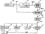
図30は、同実施形態に係わる不整脈検出装置の電気的構成を示すブロック図である。
図31は、同実施形態に係わる脈波波形、体動波形等を示す波形図である。
図32は、同実施形態の動作を説明するためのタイミングチャートである。
図33は、本発明の好適な第5実施形態に係わる不整脈検出装置の電気的構成を示すブロック図である。
図34は、同実施形態に係わる体動分離部19の構成を示す回路図である。
図35は、同実施形態の動作を説明するためのタイミングチャートである。
図36は、変形例に係わるフィルタバンクの構成を示すブロック図である。
図37は、変形例に係わる光電式脈波センサの回路図である。
図38は、変形例に係わる光電式脈波センサの使用状態を説明するための図である。
図39は、変形例に係わる光電式脈波センサが接続された装置を眼鏡に取り付けた様子を表わす斜視図である。
図40は、変形例に係わる第1のウェーブレット変換手段の回路図である。
図41は、変形例において拍数とピッチの関係を説明するための図である。
図42は、脈波波形を示す図であり、(a)は通常の脈派、(b)は不整脈の脈派を示す。
図43は、本発明における告知例を示す図であり、(a)は月毎、(b)は曜日毎、(c)は時間帯毎のヒストグラムを示す。
図44は、本発明において記憶されるタイムスタンプの一例を示す図である。
発明を実施するための最良の形態
以下、図面を参照し本発明の好適な実施形態について説明する。
まず、本発明の実施形態の説明に先立って、本発明の基本的な技術的思想について述べる。
通常、運動時と非運動時とでは程度の差があるものの、いずれの場合でも、生体の状態が正常であれば、拍動が急激に変動することは希であり、すなわち脈波波形の時間変化は連続的(規則的)となる。一方、不整脈には様々なタイプがあるが、いずれにせよ、上記連続的変化を断つような拍動は不整脈であるといえる。したがって、脈波波形の不規則な変化を検出することにより、不整脈の発生を検出することができる。これが本発明の基本的な技術的思想である。
図1は、上述した技術的思想に基づいた不整脈検出装置の概略構成を示す図であり、この図に示す不整脈検出装置は、非侵襲的に脈動を検出して脈波信号(脈波波形)を出力する脈波検出手段と、体動を検出して体動信号(体動波形)を出力する体動検出手段と、上記脈波信号および上記体動信号に基づいて不整脈発生の有無を検出する不整脈検出手段とを備えている。脈波検出手段が検出する脈動には、生体の体動の影響が現れるので、脈波検出手段から出力される脈波信号には、脈波成分のみならず、体動成分も存在する。そこで、不整脈検出手段は、脈波検出手段が出力した脈波信号から上記体動信号で特定される体動成分を除いた脈波成分で表される純粋な脈波波形を監視し、この純粋な脈波波形の不規則な変化を検出した場合には不整脈が発生した旨の情報(不整脈検出信号)を出力するようにしている。
1.第1実施形態
1−1.第1実施形態の構成
図2は、本発明の第1実施形態による不整脈検出装置の構成を示すブロック図であり、この図に示す不整脈検出装置は、不整脈の検出、不整脈数の計数、脈拍数の算出等を行うものである。図において、301は、生体の脈動を検出し、検出した脈動に応じた脈波信号を脈波信号増幅回路303に出力する脈波センサであり、例えば、圧電センサで実現される。また、302は、生体の動きを検出し、検出した体動に応じた体動信号を体動信号増幅回路304(後述する)に出力する体動センサであり、例えば、加速度センサによって実現される。
303は、検出された脈波信号を増幅し、後述するA/D変換回路305および脈波波形整形回路306に出力する脈波信号増幅回路であり、体動信号増幅回路304は、検出された体動信号を増幅し、A/D変換回路305および体動波形整形回路307(後述する)に出力する。また、A/D変換回路305は、増幅された脈波信号と体動信号をA/D変換し、後述するCPU308に出力する。
脈波波形整形回路306は、増幅された脈波信号を整形し、CPU308に出力するものであり、体動波形整形回路307は、増幅された体動信号を整形し、CPU308に出力するものである。また、CPU308は、図示せぬ記憶手段(例えばROM)に格納されたプログラムを実行するものであり、本装置の各部を制御すると共に、後述する動作を行うことによって、不整脈の検出、不整脈数の計数、脈拍数の算出等を行う。さらに、309は、CPU308のワークメモリとして用いられるRAMである。
311は、一定周期のクロックパルスを生成する発振回路、312は、発振回路311が生成したクロックパルスを分周して、所定周期のパルスを生成する分周回路、313は、液晶表示器で構成され、検出結果を表示する表示部、310は、使用者の指示を入力するための入力部であり、図3に示すように、各種設定値の決定に用いられるセットスイッチSに代表される複数のスイッチを有する。
図3は、上述した構成の不整脈検出装置の外観例を示す斜視図であり、この図に示すように、本実施形態における不整脈検出装置は腕時計形態を採用している。すなわち、本装置は、不整脈検出機能のみならず、現在時刻を計時する時計機能(リアルタイムクロック)をも備え、両機能による処理を同時に実行可能に構成されている。なお、各機能において、各種設定値の設定は、図示せぬインタフェースを介して外部から供給される信号に応じて自動的に行うようにしても良いし、上述のセットスイッチSやモード(設定モード/測定モード)を切り替えるモードスイッチを用いて行うようにしてもよい。また、本実施形態における時計機能は、計時結果(時刻情報)が不整脈の検出時刻を記録するために使用される点を除いて周知のデジタル時計のものと同様であるので、ここでは時計機能を実現する構成やその動作に関する説明を省略する。
また、図3において、1は装置本体であり、バンド144によって使用者の腕に取り付けられている。また、上記脈波センサ301および体動センサ302(図2参照)は、センサ固定用バンド52によって使用者の指に固定されている。なお、本装置の外観は後述する第3〜第4実施形態による不整脈検出装置とおよそ同様であり、外観構成については第3実施形態において詳細に説明するので、ここでは簡単な説明に止める。
1−2.第1実施形態の動作
上記構成による不整脈検出装置の不整脈検出モードにおける動作は2種類の動作に大別され、体動の検出状況に応じて各動作が切り換えられる。以下、これらの2種類の動作をそれぞれ「第1の不整脈検出動作」,「第2の不整脈検出動作」と呼び、個々に説明する。
1−2−1.第1の不整脈検出動作
▲1▼ 使用者が計測の開始を表すスイッチを押下することにより、本装置は、後述する「1−2−3.脈波波形検出方法」によって脈波波形を検出する。
▲2▼ CPU308は、上記脈波波形を構成する各脈波間の間隔値(脈波間隔値)について、スタート直後の所定数の脈波間隔値の平均値を求め、この平均値を脈波間隔値の初期値とするとともに、この初期値の逆数に60を乗算した値を脈拍数の初期値とする。
▲3▼ CPU308は、上記脈波波間値の初期値を基準脈波間隔値Iとする。
▲4▼ CPU308は、任意の時点tnにおける脈波間の間隔値inを求め、この間隔値inを上記基準脈波間隔値Iで除算する。
▲5▼ CPU308は、▲4▼での除算結果が予め求められた許容範囲(適正な変動範囲)外である場合には、不整脈が発生したものと判断し、内部のレジスタによって実現している不整脈カウンタをインクリメントするとともに、前回算出された脈拍数をそのまま今回の脈拍数として設定する。なお、ここでは、不整脈発生の判断基準とする許容範囲を、脈拍数領域において前回の脈拍数を中心とした所定範囲に対応する範囲としている。例えば、上記所定範囲を±5%とし、基準脈波間隔値Iが約0.3529s、前回の脈拍数が170拍/分とすると、170×0.05=8.5であることから、脈拍数領域での範囲は161.5〜178.5拍/分となる。この範囲に相当する時間領域での範囲は、60/161.5≒0.3715、60/178.5≒0.3361であることから、約0.3361〜0.3715sとなる。0.3361/0.3529≒0.9524、0.3715/0.3529≒1.0527であるので、除算結果の許容範囲は、約0.9524〜1.0527となる。
▲6▼ CPU308は、▲4▼での除算結果が上記許容範囲内である場合には、上記間隔値inを基準脈波間隔値Iとするとともに、当該間隔値inをRAM309の間隔値領域に順に記憶させ、RAM309の間隔値領域に記憶された最新の所定数の間隔値の平均値の逆数に60を乗算して脈拍数を算出する。
▲7▼ CPU308は、不整脈カウンタのカウント値および脈拍数を表示部313により表示する。
▲8▼ CPU308は、使用者が計測の終了を表すスイッチを押すまで、▲4▼〜▲7▼の動作を繰り返す。なお、不整脈カウンタのカウント値をリアルタイム表示せずに、使用者が上記スイッチを押下したときに初めて表示するようにしてもよい。
1−2−2.第2の不整脈検出動作
▲1▼ 使用者が計測の開始を表すスイッチを押下すると、本装置は、後述する「1−2−3.脈波波形検出方法」により脈波波形を検出する。
▲2▼ CPU308は、▲1▼で求めた脈波波形について、脈波の基本波の周波数スペクトルを中心(メインローブ)とする近傍(サイドローブ)の周波数スペクトルについて、その振幅値(パワー)が所定値以上である周波数スペクトルを取り出す。
▲3▼ CPU308は、▲2▼で取り出した周波数スペクトルが不規則な値を示していないか否かを判定する。
ここで、上記「不規則」について説明する。図42(a)は、不整脈がない場合の橈骨脈波を、図42(b)は不整脈がある場合の橈骨脈派波形を示す図であり、両者を比較して明らかなように、不整脈により、図42(b)中の2番目の脈派波形が扁平になつている。不整脈により脈派波形にこのような変形が生じることは、指尖脈派においても同様であるので、指尖脈派波形については図示を省略する。
次に、図4は、不整脈がない場合における指尖脈波のFFT処理結果の一例を示すグラフである。同様に、図5は不整脈がある場合における指尖脈波のFFT処理結果の一例を示すグラフ、図6は不整脈がない場合における橈骨脈波のFFT処理結果の一例を示すグラフ、図7は不整脈がある場合における橈骨脈波のFFT処理結果の一例を示すグラフである。これらのグラフからも明らかなように、FFTの分析時間内の脈波波形中に不整脈による脈波が存在する場合には、基線が立ち上がらなくなり、FFTによる周波数解析が成り立たなくなる。CPU308は、このことを利用して、不整脈の発生を検出するのである。
▲4▼ 不整脈の発生を検出すると、CPU308は、このことを表示部313により表示するとともに、前回の脈拍数をそのまま今回の脈拍数として表示部313により表示させる。
▲5▼ 不整脈の発生を検出しなかった場合には、CPU308は、▲2▼で取り出したスペクトルの周波数に60を乗算して脈拍数を算出し、この脈拍数を表示部313により表示する。
第2の不整脈検出動作における▲2▼,▲3▼の処理は、具体的には、以下の手順で行われる。
(I)脈波信号に対するFFT処理結果(スペクトラム)から、脈波の基本波の周波数が存在し得る範囲(一般には0.6〜3.5Hz)内において、体動成分を除いてパワーが最大の周波数スペクトルを選択し、当該スペクトルのパワーが所定値以上であり、かつ上記範囲内の体動成分を除いた他の基線とのパワー差が30%以上である場合に、当該スペクトルを脈波の基本波の周波数スペクトルとして取り出し、
(II)取り出した周波数スペクトルをメインローブとするサイドローブが適切に広がっており、かつ当該スペクトルの周波数が予想される許容範囲内に存在する場合には、不整脈は存在しないと判定する。
なお、ここでは、取り出した周波数スペクトルをメインローブとするサイドローブが適正に広がっているか否かは、当該スペクトルのパワーの95%値よりも当該スペクトルに隣接する両スペクトルのパワーが小さいか否かで判断している。また、ここでは、脈波の基本波の周波数の許容範囲を、脈拍数領域において前回の脈拍数を中心とした所定範囲に対応する周波数領域での範囲としている。例えば、前回の脈拍数を170拍/分(脈波の基本波の周波数は約2.8333Hz)、脈拍数領域における許容範囲を±5%とすると、周波数領域での許容範囲も前回の脈波の基本波の周波数を中心とする±5%の範囲(約2.8333±0.1417Hz)となる。一方、1回のFFT処理に必要な分析時間を16sとすると、各スペクトルは1/16=0.0625Hz間隔で得られる。すなわち、拍動周波数近辺では、2.6875,2.7500,2.8750,2.9375,3.0000Hzというように、離散した周波数のスペクトルが得られる。したがって、取り出したスペクトルの周波数を上記離散した周波数と比較することにより、許容範囲内であるか否かを判断することができる。もちろん、このようなスペクトルの離散性を考慮せずに、取り出したスペクトルの周波数と周波数領域の連続した許容範囲(約2.8333±0.1417Hz)とを比較するようにしてもよい。
ところで、上述した例では、2.6875<2.8333−0.1417<2.7500であり、2.9375<2.8333+0.1417<3.0000であることから明らかなように、2.7500〜2.9375Hzの3つのスペクトルは連続した許容範囲に含まれ、2.6875、3.0000Hzの2つのスペクトルは連続した許容範囲に含まれていない。したがって、2.6875、3.0000Hzの2つのスペクトルを考慮する態様と、考慮しない態様が考えられるが、本実施形態では、正常な拍動を不整脈として検出してしまう事態を極力避けるために、前者を採用している。したがって、本実施形態では、取り出したスペクトルの周波数が2.6875,2.7500,2.8750,2.9375,3.0000Hzのいずれかであれば、不整脈は発生していないと判定される。
1−2−3.脈波波形検出方法
図8は、本装置による脈波波形検出動作の一例を示すフローチャートであり、この図に示す例では、CPU308は、ステップSA1において、体動波形整形回路307の出力信号(体動信号)から体動波形を検出し、続くステップSA2において、上記体動波形に基づいて体動があるか否かを判断する。この判断結果が「YES」の場合には、処理はステップSA3へ進み、該判断結果が「NO」の場合には、処理はステップSA7へ進む。
ステップSA3では、脈波センサ301が拍動を検出して脈波信号を出力し、当該脈波信号を脈波信号増幅回路303が増幅し、増幅された脈波信号をA/D変換回路305がA/D変換する。ステップSA4では、体動センサ302が体動を検出して体動信号を出力し、この体動信号を体動信号増幅回路304が増幅し、増幅された体動信号をA/D変換回路305がA/D変換する。なお、実際には、上記ステップSA3,SA4の処理は並行して行われる。そして、CPU308は、A/D変換された脈波信号(脈波波形)および体動信号(体動波形)をそれぞれFFT処理し(ステップSA5)、FFT処理結果(スペクトラム)に基づいて、後述する手法にて脈波の周波数成分(脈波成分)を抽出する(ステップSA6)。
一方、CPU308は、ステップSA7において、脈波波形整形回路306の出力信号(脈波信号)から脈波波形を検出し、続くステップSA8において、体動があるか否かをもう一度判断する。この判断結果が「YES」の場合には、処理はステップSA3へ進み、「NO」の場合には、処理はステップSA9へ進む。ステップSA9では、CPU308は脈波波形を矩形波に変換する。
ステップSA10では、CPU308は、ステップSA6で抽出された脈波成分、または、ステップSA9で変換された矩形波から、脈拍数を演算する。
次に、脈波波形整形回路306から出力される脈波信号から脈波成分(純粋な脈波波形)を求める処理の基本的方針について説明する。
図9(a)は、周波数fAの信号と周波数fB(但し、周波数fBの信号の振幅は、周波数fAの信号の1/2)の信号とを加算した信号の振幅の時間変化を示す図であり、図9(b)は、図9(a)に示す信号をFFT処理した結果を示すグラフである。前述したように、FFT処理した結果として得られる最も低い周波数は、分析時間の逆数で決定される。例えば、分析時間を16sとすると線スペクトルは1/16s、すなわち62.5msの分解能で得られる。したがって、処理対象の信号は周波数領域において16Hzの整数倍の高調波成分に分解され、各高周波成分のパワーを縦軸で表した図9(b)のようなスペクトラムが得られる。例えば、図9(b)において、周波数fAのスペクトルのパワーは周波数fBのスペクトルのパワーの2倍となっている。
図10は、運動状態での脈波センサ301からの出力信号と体動センサ302からの出力信号とをFFT処理した結果の一例を示すグラフであり、(a)は脈波センサ301の出力信号(脈波信号)をFFT処理した結果(脈波スペクトラムfmg)を表し、(b)は体動センサ302の出力信号(体動信号)をFFT処理した結果(体動スペクトラム(fsg)を表し、(c)は脈波スペクトルfsgから体動スペクトラムfsgを引いて得られるスペクトラムfMを表す。
図10(a)に示すように、脈波スペクトラムfmgには、脈波成分と体動によって発生した周波数成分との両方が乗ってくる。一方、体動センサ302は体動だけに反応するので、図11(b)の体動スペクトラムfsgには、体動によって発生した周波数成分のみが乗ってくる。したがって、脈波スペクトラムfmgから体動スペクトラムfsgを引き、得られたスペクトラムfMを脈波成分のスペクトラムとして特定することができる。図8のステップSA6では、このような方法によって脈波成分を抽出している。
次に、脈拍数の演算にて必要とされる脈波の基本波の周波数の求め方について説明する。
図11は、脈波の基本波の周波数の特定方法の一例を示すフローチャートであり、この図において、CPU308は、まず、FFT処理によって脈波スペクトラムfmgと体動スペクトラムfsgとを求めている(ステップSB1,SB2)。CPU308は、続くステップSB3では、前述した減算処理(fM=fmg−fsg)を行い、脈波成分のスペクトラムfMを取り出し、続くステップSB4,SB5では、取り出したスペクトラムfMから最大パワーのスペクトルを抽出し、このスペクトルの周波数fMmaxを脈波の基本波の周波数として特定する。
ところで、実際には、それぞれのセンサ出力信号をFFT処理して単純に差をとっても、高調波信号の影響があり、脈波成分のみに対応したスペクトラムを得るのが難しい場合がある。そこで、本実施形態では、スペクトラムの減算を行うのではなく、体動成分を特定し、特定した体動成分を除く周波数成分から脈波の基本波の周波数を特定するようにしている。
図12は、脈波の基本波の周波数の特定方法の他の例を示すフローチャートであり、この図に示す例では、CPU308は、ステップSC1〜SC3において、体動成分として比較的検出し易い体動の第2高調波の周波数fs2を特定している。この処理は、実際には、fmax〜fminの範囲(ただし、fmax>fmin)における最大パワーのスペクトルを抽出し、その周波数fsを体動の第2高調波の周波数fs2とすることで実現される。
ところで、使用者が行う運動を例えば「走行」とした場合、通常、その際の体動の基本波が出現し得る周波数範囲は1〜2Hzとなり、体動の第2高調波が出現し得る周波数範囲は2〜4Hzとなるので、本実施形態では、fminを体動の第2高調波の下限周波数である2Hzとし、当該下限周波数以下の周波数成分を除外している。一方、体動信号のA/D変換のサンプリング周波数を8Hzとすると、サンプリング定理から、原波形が再現できる最高周波数は4Hzと自動的に決まる。そこで、本実施形態では、fmaxを上記最高周波数である4Hzとし、当該周波数以上の周波数成分を除外している。なお、fmaxについては、第2高調波が出現し得る上限周波数と上記最高周波数とを比較し、より低い周波数を採用するようにしてもよい。
次に、CPU308は、ステップSC4において、体動の第2高調波の周波数fs2を2で除算して体動の基本波の周波数fs1を求め、ステップSC5〜SC8において、脈波信号のスペクトラムから、体動の基本波(周波数はfs1),第2高調波(周波数は2×fs1),第3高調波(周波数は3×fs1)に相当する周波数成分を除外した周波数帯において最大パワーのスペクトルを抽出し、ステップSC9において、当該最大パワーのスペクトルの周波数を脈波の基本波の周波数fmとして特定する。
ここで、図12に示す例において、fmin〜fmaxの周波数帯の最大パワーのスペクトルを抽出し、その周波数を体動成分の第2高調波として扱っている理由について述べる。
図13は、体動センサ302の出力をFFT処理した結果の一例を示す図であり、一般に、運動状態、特に走行状態においては、図13のごとく体動の基本波に比べて体動の第2高調波のパワーがより大きくなる(ごく平均的な走り方をしている時で、3〜10倍程度)。ここで、体動センサ302の加速度検知要因について分析してみると、当該要因として、以下の2つが考えられる。
(1)走行時の上下動
(2)腕の振り出し〜引き戻し
(1)に関しては、右足をステップした時と左足をステップした時に均等に上下動が出るので体動の第2高調波成分となる。(2)に関しては、腕の振り出し〜引き戻しを一周期とする振り子運動に相当する成分は体動の基本波成分となるが、通常走行において腕の振りを滑らかな振り子運動にするのは難しく、この成分のパワーは弱めとなる。逆に、腕の振り出し、引き戻しのそれぞれの瞬間に加速度がかかる為に発生する体動の第2高調波成分のパワーは強めとなる。したがって、体動信号のスペクトラムにおいて、体動の第2高調波成分が特徴的に得られることになる。よって、最大パワーのスペクトルの周波数を体動成分の第2高調波の周波数として扱うことができるのである。
さらに、前述したように、通常走行では、2〜4Hzの範囲であれば走行ペースの速い遅いを考えても第2高調波が出現する領域をカバーできる。したがって、この領域に限定した上で最大パワーの周波数成分を抽出することで、体動の第2高調波に対応した周波数成分を確実に抽出することができ、ひいては体動の基本波の周波数の検出精度を上げることができる。
次に、体動信号のスペクトラムにおいて、体動の第2高調波の周波数成分のパワーが最大になるとは限らない状況下で、脈波の基本波周波数を特定する方法について、図14を参照して説明する。
体動の基本波の周波数を1〜2Hzとし、fmin=2Hz,fmax=4Hzとすると、fmin〜fmaxの範囲において最大パワーとなり得るのは、体動の基本波、第2高調波、第3高調波の周波数成分である。なお、第4高調波以降は前述の主要な(1),(2)の要因に起因していないので、存在したとしてもその周波数成分のパワーがfmin〜fmaxの範囲において最大となることはない。
このような事情に鑑みて、図14に示す方法では、CPU308は、ステップSD1において、体動信号の周波数分析結果に基づいて、パワーPが最大の線スペクトルの周波数fsを求めた後に、ステップSD2およびSD4により、周波数fsが体動の基本波、第2高調波、第3高調波のいずれの周波数成分であるかを特定している。具体的には、CPU308は、周波数fsの1/2の周波数位置に、ある一定値Th以上の周波数成分が存在しているか否かを判断し(ステップSD2)、この判断結果が「YES」の場合には、ステップSD3において、周波数fsを体動の第2高調波(HMC=2)の周波数fs2として特定する。ステップSD2での判断結果が「NO」の場合、すなわち、ある一定値Th以上の周波数成分が存在しない場合には、さらに、fsの1/3の周波数位置に、ある一定値Th以上の周波数成分が存在しているか否かを判断し(ステップSD4)、この判断結果が「YES」の場合には、ステップSD5において、周波数fsを体動の第3高調波(HMC=3)の周波数fs3として特定する。ステップSD4での判断結果が「NO」の場合、すなわち、fsの2/1および1/3の周波数位置にある一定値Th以上の周波数成分が存在しない場合には、ステップSD6において、周波数fsを体動の基本波の周波数fs1として特定する。
以上の処理により、ステップSD1で求めた周波数fsが、体動の基本波(HMC=1)、第2高調波(HMC=2)、第3高調波(HMC=3)のいずれの周波数であるかが特定され、ステップSD7では、CPU308が、周波数fsをHMCで除算することで、体動の基本波の周波数fs1が求められる。以降、図12のステップSC5〜SC9と同一の処理により、CPU308は、体動成分の基本波、第2高調波、第3高調波と一致する周波数成分を除外した最大の周波数成分を抽出し、これを脈波の基本波の周波数fmとして特定する(ステップSD8〜SD12)。
ところで、図8においては、体動信号が検出されなくなると、即座に矩形波処理に移行する例を示したが、実際には、運動中であっても体動信号の瞬時値によっては「非検出」とされる場合があり得ることを考慮し、体動信号が検出されない期間がある一定時間Tを超えてから演算方法を矩形波処理による方法に切り替えるようにしている。この切り替え手順について、図15を参照して説明する。
CPU308は、ステップSE1およびSE2では、体動波形整形回路307の出力信号(体動信号)により体動があるか否かを判断する。この判断結果が「YES」の場合には、処理はステップSE3へ進む。ステップSE3では、CPU308は、脈拍数の演算方法を切り替えるための切替信号を“OFF"にし、ステップSE4では、体動無しの累積時間Rtをゼロにする。
続くステップSE5およびSE6では、脈波センサ301が拍動を検出して脈波信号を出力し、この脈波信号を脈波信号増幅回路303が増幅し、増幅された脈波信号をA/D変換回路305がA/D変換するとともに、体動センサ302が体動を検出して体動信号を出力し、この体動信号を体動信号増幅回路304が増幅し、増幅された体動信号をA/D変換回路305がA/D変換する。
CPU308は、続くステップSE7において、A/D変換された体動信号および脈波信号をそれぞれFFT処理し、ステップSE8において、FFT処理結果(スペクトラム)から脈波成分(純粋な脈波波形)を抽出し、脈波の基本波の周波数を特定する。
一方、ステップSE2での判断結果が「NO」の場合には、CPU308は、ステップSE9およびSE10において、発振回路311および分周回路312からの出力信号に基づく計時を開始し、時間Rtを累積し、累積時間Rtが、FFT処理の際に用いられる信号のサンプリング周期あるいはサンプリング数などによって決められるある一定時間Tを超えているか否かを判断する。この判断結果が「YES」の場合には、処理はステップSE11へ進み、「NO」の場合には、処理は前述のステップSE5へ進む。
CPU308は、ステップSE11において、脈拍数の演算方法を切り替えるための切替信号を“ON"にし、A/D変換処理及びFFT処理を停止させる。なお、矩形波処理を行う場合にもA/D変換処理およびFFT処理を並行して行うようにしてもよいが、消費電力の観点からは、矩形は処理を行う場合には周波数分析処理にのみ必要となるA/D変換処理およびFFT処理を停止させた方がよい。
そして、CPU308は、ステップSE12において、脈波波形整形回路306が脈波信号を矩形波に変換し、ステップSE13において、CPU308がステップSE7で特定された周波数、またはステップSE12において変換された矩形波から脈拍数を演算する。
2.第1実施形態の変形例
ところで、不整脈には、その発生原因によって危険なものと危険性が極めて少ないものとがある。しかし、脈は人体の健康状態を表すものであるから、不整脈のように乱れた脈は好ましいものではなく、乱れるということは、何らかの体調の異常があるといえる。仮に疾患のない正常な人であっても、睡眠不足であれば不整脈が発生する。また、コーヒーを飲み過ぎた時や心理的なストレスが過剰になった時にも不整脈は発生する。したがって、不整脈の検出回数を参照すれば、人の健康の程度を知ることができる。
また、正常な人に発生する不正脈と異なり、重大な心臓、血管系の病気に伴って起こってくる不整脈は、単源性でも一日200回以上出現するとか、多源性でいろいろな形態をとる心電図を呈することが知られている。したがって、閾値を例えば200個に設定し、これを越える場合にその旨を使用者に告知することにより、使用者に警告を与えることができる。
また、心臓・血管系の病気を患っている場合、短時間に不整脈が多発すると、人体が危険な状態に陥ることがあり、また、最悪の場合には突然死に至ることもあり得る。そこで、不整脈の発生頻度を告知するようにすれば、使用者は自己の健康状態を管理することができる。例えば、待ち合わせの時間に遅れそうになって駆け出すような時に、上記発生頻度を表示させ、その値が大きい場合には、走るのを思い止まることができる。
また、睡眠中に不整脈が多発し、危険な状態に陥った場合には、不整脈の発生頻度情報FHDが閾値を越えてブザー17が発音するので、使用者に危険な状態にあることを知らせることができる。これにより、使用者は投薬等の適切な処置を取ることができ、突然死といった最悪の事態を回避することができる。
すなわち、上述した第1実施形態において、計測開始時点からの経過時間を測定し、不整脈の検出頻度あるいは検出回数が所定の頻度(例えば200回/日)あるいは回数(例えば200回)を超過した場合に、その旨を告知して使用者の注意を喚起するようにしてもよい。この際の告知時期は超過時点であってもよいし、測定終了時や測定終了後の問い合わせ時であってもよいが、使用者が運動の強度を制御するための判断材料になり得ることから、超過時点で告知するのが好ましい。なお、告知の態様については「4.各実施形態の変形例」において後述する。
また、脈波間隔値の基準値の更新時に、最新の脈波間隔値をそのまま基準値とするのではなく、最新の所定数の脈波間隔値の平均値を新たな基準値とするようにしてもよい。この際、より新しい脈波間隔値の比重が高くなるよう、重み付けして平均値を求めるようにしてもよい。このことは、最新の所定数の脈波間隔値に基づいて脈拍数を算出する場合にも同様に適用可能である。
さらに、不整脈が検出されなかった場合にのみ、脈波間隔値をRAM309に記憶させるのではなく、全ての脈波間隔値をRAM309に順に記憶させ、不整脈検出時の脈波間隔値を除く脈波間隔値に基づいて脈拍数や脈波間隔値の基準値を算出するようにしてもよい。この際、不整脈検出時の脈波間隔値であるか否かを判断する必要があるが、これは、例えば、不整脈検出時の脈波間隔値にのみ所定の情報を対応付けてRAM309に記憶させることで実現可能である。なお、不整脈検出時に脈波間隔値に対応付ける所定の情報としては、不整脈検出時の脈波間隔値であることのみを示す固定情報や、不整脈検出時刻を示す可変情報であってもよい。もちろん、脈波間隔値に直接的に上記所定の情報を対応付けるようにしても良いし、脈波間隔値が格納されたアドレス等を用いて間接的に上記所定の情報を対応付けるようにしてもよい。
また、矩形波処理時(非運動時)において、脈波間隔値の基準値に対する最新の脈波間隔値の差異(ズレ)が許容範囲内であるか否かを除算以外の手法で求めるようにしてもよい。例えば、脈波間隔値の基準値の±5%の範囲を求め、最新の脈波間隔値が当該範囲内に存在するか否かを判断するようにしてもよい。さらに、不整脈検出動作の開始直後からの脈波間隔値に基づいて基準値を求めるのではなく、動作開始時点から所定時間経過した後に検出された脈波間隔値に基づいて基準値を求めるようにしてもよい。
ところで、脈波信号には、脈波の基本波成分のみならず、脈波の高調波成分も含まれており、基本波成分のパワーよりも高調波成分のパワーの方が大きい場合には、上述した第1実施形態では、高調波成分の周波数が基本波成分の許容範囲内に存在するか否かが判断され、結果として、不整脈が発生していると判定されてしまう。このような誤判定を避けるために、周波数分析において、脈波成分における最大パワーのスペクトルの周波数が、前回の脈拍数を60で除算した値(拍動周波数)の定数倍(各高調波の周波数)に一致した場合に不整脈は存在しないと判定するようにしてもよい。
また、体動がない場合は矩形波処理、体動がある場合は周波数分析処理を行うようにしたが、いずれの場合にも周波数分析処理を行うようにしてもよいし、脈波信号から脈波以外の成分を除去する手段(例えばフィルタ)を脈波信号の入力段に設けることが可能であれば、上記両場合に矩形波処理を適用するようにしてもよい。さらに、これらの態様では、脈波信号からの体動成分の除外処理を、体動の有無に関わらずに常に行うようにすることができる。この際、体動が無い場合には、上記除外処理を行っても脈波成分から除外される成分は存在しないので、体動の有無に応じて処理内容を変更する第1実施形態と同様の結果が得られる。
また、矩形波処理において、実際の脈派間隔値と基準脈波間隔値との差異を告知するようにしてもよい。これにより、脈派のずれの程度が定量化される。
3.第2実施形態
ところで、健康な人でも、走行などの強運動時には不整脈が発生することがあり、このような不整脈の発生状況を把握することは、運動時の体調管理に役立つことが予想される。しかしながら、第1実施形態においては、強運動時であるか否かに関わらず、不整脈の検出処理を行っており、強運動時の不整脈とそれ以外の運動時の不整脈とを区別できない。そこで、走行などの強運動時の体動が定常性を有することを利用し、強運動等の体動ピッチに定常性がある運動時の不整脈のみを検出するようにしたのが本発明の第2実施形態である。
以下、図面を参照して、この発明の第2実施形態について説明する。第2実施形態による不整脈検出装置は、第1実施形態によるものと同様に、図3に示すような腕時計形態で実現され、時計モードと不整脈検出モードとを有し、不整脈検出モードにあっては、不整脈の検出、不整脈数の計数、脈拍数の算出を行うものであり、第1実施形態によるものと共通する部分については、その説明を省略する。
3−1.第2実施形態の構成
第2実施形態による不整脈検出装置の構成は、図2に示す構成と略同一であり、CPU308の機能のみが第1実施形態によるものと異なっている。
第2実施形態による不整脈検出装置のCPU308が第1実施形態におけるものと異なる点は、不整脈検出モードにおいて、体動に定常性がある場合にのみ不整脈の検出を行う点である。体動に定常性があるか否かは、第1実施形態において周波数分析によって不整脈の有無を判定する際に脈波信号に対して施した処理と同様の処理を体動信号に施すことにより判断可能であり、この判断の詳細については、第2実施形態の動作の説明において詳述する。なお、第1実施形態における不整脈の検出処理では、基本的に脈波の基本波を特定して不整脈の有無を判断しているが、第2実施形態においては、体動の第2高調波を特定して体動の定常性を判断している。
3−2.第2実施形態の動作
次に、第2実施形態による不整脈検出装置の動作(不整脈検出モードの動作)について説明する。第2実施形態においても、不整脈検出モードの動作は、「第1の不整脈検出動作」と「第2の不整脈検出動作」とに大別される。前者については、第1実施形態における第1の不整脈検出動作と同一の動作であるので、その説明を省略する。
3−2−1.第2実施形態における第2の不整脈検出動作の特徴
第2実施形態における第2の不整脈検出動作が第1実施形態における動作と異なる点は、体動に定常性がある場合には、脈波信号の周波数解析結果から不整脈の有無を判定する処理を行い、体動に定常性がない場合には、同処理を行わない点である。
3−2−2.体動の定常性の判断手法
ここで、体動に定常性があるか否かの判断手法の例として、「時間領域での判断手法」および「周波数領域での判断手法」を挙げる。
3−2−2−1.時間領域での判断手法
時間領域での判断手法としては、脈拍数領域での所定範囲(例えば±5%)に応じた体動の第2高調波の波間値の範囲(時間領域での範囲)を許容範囲とし、体動の第2高調波の波間値が当該許容範囲内に存在する場合には「定常性あり」と判断し、当該許容範囲内に存在しない場合には「定常性なし」と判断する手法が挙げられる。
例えば、脈拍数が170拍/分とすると、170×0.05=8.5であることから、脈拍数領域での±5%範囲は±8.5拍/分となり、周波数領域での相当する範囲は±0.1417Hzとなる。ここで、脈波の基本波が存在し得る周波数範囲(一般には0.6Hz〜3.5Hz)と体動の第2高調波の間隔値となり得る時間範囲(0.5〜0.25s)とが線形に対応すると仮定すると、±0.1417Hzに相当する体動の第2高調波の間隔値に関する時間領域での許容範囲は±0.1417×(0.5−0.25)/(3.5−0.6)≒±0.0122となる。したがって、体動の第2高調波の間隔値の基準値を0.28sと仮定すると、体動の第2高調波の間隔値が0.28±0.0122sの範囲内に存在する場合には「定常性あり」、それ以外の場合には「定常性なし」と判断される。
3−2−2−2.周波数領域での判断手法
周波数領域での判断手法としては、体動信号の周波数解析結果から体動の第2高調波のスペクトルが存在し得る範囲(2Hz〜4Hz)において最も高パワーの周波数スペクトルを抽出し、当該スペクトルのサイドローブが適正に広がっており、かつ、上記範囲内の他のスペクトルとのパワー差が十分(例えば30%以上)である場合には、当該スペクトルの周波数が前回の脈拍数に相当する周波数(体動の基本波の周波数)の2倍に一致するか否かを判定し、一致した場合には「定常性あり」と判断する手法が挙げられる。なお、サイドローブが適正に広がっているか否かは、第1実施形態と同様な手法で判断できる。また、第1実施形態と同様に、上記「一致」は厳密な一致ではなく、以下に述べる許容範囲が存在する。
「一致」の許容範囲は、任意に設定可能であるが、体動の基本波の周波数と脈拍数との間には相関があり、第1実施形態と同様に不整脈の検出において脈拍数に関する「一致」の許容範囲を設定していることから、本実施形態では、脈拍数に関する「一致」の許容範囲に相当する範囲を体動の第2高調波に関する「一致」の許容範囲としている。
例えば、脈拍数が170拍/分(脈波の基本波の周波数は約2.833Hz)であり、脈拍数に関する「一致」の許容範囲が±5%であるとすると、脈波の基本波の周波数に関する許容範囲(周波数領域の許容範囲)も±5%、すなわち±0.1417Hzとなる。ここで、脈波の基本波が存在し得る周波数範囲(0.6Hz〜3.5Hz)と体動の第2高調波が存在し得る周波数範囲(2Hz〜4Hz)とが線形に対応すると仮定すると、上記許容範囲(±0.1417Hz)に対応する脈波の第2高調波に関する許容範囲は±0.1417×(4−2)/(3.5−0.6)=±0.0977Hzとなる。一方、周波数解析の分析時間を16sとすると、前回の脈拍数に相当する周波数の2倍(例えば3.53Hz)近辺では3.3750,3.4375,3.5000,3.5625,3.6250,3.7667Hzというように、離散した周波数でのスペクトルが得られる。したがって、体動の第2高調波のスペクトルとして選択したスペクトルが上記各離散スペクトルのいずれかであるならば、3.53±0.0977Hzの範囲内であるので、「一致」と判断し、それ以外の場合には「不一致」と判断する。
上述した一致判定を行う理由は、体動が階段状に変化した場合にも、体動に「定常性なし」と判断して不整脈の検出動作を行わないようにするためである。例えば、使用者が定常性のある運動のピッチを急激に変化させ、しかもこの変化が前回の周波数解析の対象期間から今回の周波数解析の対象期間への移行時点で生じた場合には、前回の周波数解析結果に基づいて特定された体動の第2高調波の周波数と、今回の周波数解析結果に基づいて特定された体動の第2高調波の周波数とが異なり、体動に「定常性あり」と判断すべきではない。なお、周波数解析の分析時間が十分に長い場合には、上述した「一致」の判断を省略しても、体動に定常性がないときに不整脈を検出してしまう、といった問題は生じない。
なお、体動の第2高調波の周波数成分のパワーが他の周波数成分のパワーよりも強くなるとは限らない状況下では、図14に示す処理と同様の処理が行われる。すなわち、予想される周波数範囲(例えば、2〜4Hz)において最大パワーの周波数成分は、体動の基本波、第2高調波、第3高調波のいずれかの周波数成分であるものと仮定し、当該最大パワーの周波数成分の1/2,1/3の周波数におけるパワーを調べることによって、当該周波数成分が体動の基本波、第2高調波、第3高調波のいずれの成分であるかを特定する。なお、図14においては、特定した成分に基づいて体動の基本波の周波数を特定しているが、第2実施形態では体動の第2高調波を特定することになる。
3−2−2.第2実施形態における全体の動作
ここで、図16を参照し、第2実施形態における全体の動作について説明する。なお、特に断らない限り、動作の主体はCPU308であるものとする。
図16において、ステップSF1〜SF8の処理は、図8のステップSA1〜SA5,SA7〜SA9と同一の処理であり、体動信号(体動波形)が存在する場合には、脈波信号(脈波波形)を検出し、この脈波信号に矩形波処理を施す。一方、体動信号が存在する場合には、脈波信号および体動信号を検出してA/D変換し、それぞれにFFT処理を施す。そして、ステップSF9では、体動信号のFFT処理結果に基づいて、前述した処理により、体動に定常性があるか否かを判断し、定常性がある場合には、ステップSF10にて、図8のステップSA6と同様な処理が行われる。したがって、不整脈が発生している場合には、ここで、その旨が報知される。一方、ステップSF9において体動に定常性がないと判断された場合には、ステップSF11において、脈波の基本波の周波数のみを求める処理が行われる。すなわち、ステップSF11では、不整脈の検出処理は行われず、脈波信号の周波数解析結果から脈波の基本波の周波数を求める処理のみが行われる。
そして、ステップSF12では、ステップSF5において得られた矩形波信号、またはステップSF10において得られた情報(脈波の基本波の周波数または当該周波数を特定できなかった旨)、あるいはステップSF11において得られた情報(脈波の基本波の周波数または当該周波数を特定できなかった旨)に基づいて、脈拍数が算出される。なお、ステップSF10またはSF11において脈波の基本波の周波数を特定できなかった場合には、ステップSF10では脈拍数は算出されず、前回の脈拍数が今回の脈拍数として採用される。
このように、上述した第2実施形態によれば、体動に定常性がある運動(走行などの強運動時や体動ピッチが1分間に80回程度の歩行など)時における不整脈を検出することができる。
4.第1および第2実施形態の変形例
以上、この発明の第1および第2実施形態を図面を参照して詳述してきたが、具体的な構成はこの実施形態に限られるものではなく、この発明の要旨を逸脱しない範囲の設計の変更等があってもこの発明に含まれる。
例えば、第1実施形態と前述の第2実施形態とを組み合わせ、体動の定常性に関わらずに不整脈検出を行うモードと、体動に定常性があるときに不整脈を検出するモードとを同一の不整脈検出装置に設け、使用者が選択できるようにしてもよい。
また、上述した各実施形態では、「一致」の許容範囲を固定とすることを前提としているが、これに限らず、当該許容範囲を可変としてもよい。例えば、特定のスイッチの操作に応じて当該許容範囲の幅を変動させるようにしてもよい。この際、当該許容範囲の幅を表す情報(例えば±5%)を設定者に告知するように構成するのが望ましい。また、脈波波間値の基準値や前回の脈拍数、前回の体動の基本波の周波数等に応じて、当該許容範囲の幅を動的に変更するようにしてもよい。さらに、一般に、非運動時の脈拍数の適正な変動幅は運動時に比較して小さいので、体動が無い場合の脈波の基本波の周波数に関する許容範囲を、体動が有る場合の同許容範囲よりも狭く設定すれば、より高い精度で不整脈を検出することができる。また、各種許容範囲の幅を、脈拍数や体動の基本波の周波数に依存しない絶対値とする態様も考えられる。
また、上述した各実施形態では、脈波信号および体動信号の各FFT処理結果において、対象とするスペクトルの周りにサイドローブが適正に広がっているか否かを判断しているが、これらの判断において、対象とするスペクトルに隣接したスペクトルだけでなく、所定範囲内の全てのスペクトルを考慮するようにしてもよい。例えば、対象とするスペクトルとのパワー差が、隣接するスペクトルにあっては5%以上、さらに一つ間をおいたスペクトルにあっては10%以上ある場合にのみサイドローブが適正に広がっていると判断するようにしても良いし、「一致」の許容範囲内の全スペクトルにおいて上記パワー差が5%以上ある場合にのみサイドローブが適正に広がっていると判断するようにしてもよい。
さらに、心臓が停止する等して、脈波が検出されない期間が所定時間を超過した場合には、その旨を遠隔地の監督者に知らせるようにしてもよい。このようにすれば、例えば、心臓に疾患を抱えた人等に装着させ、遠隔地の医師等の監督者が、使用者の心停止を迅速に告知することができるので、適切な措置を迅速に講じることができる。なお、この際の基準となる時間は、全ての使用者に共通の一定時間であってもよいし、各使用者毎に設定される時間であってもよい。また、緊急時に遠隔地の監督者側にその旨を知らせる具体的なシステムについては、「システム化」の欄において後述する。
また、脈波センサの装着場所は、指に限らず、脈波が測れる場所(例えば、耳、首等)ならばどこでも良い。また、体動センサとしては、加速度センサの他に、光学式センサを用いることも考えられる。また、体動センサの装着場所は、腕のみに限らず、使用者の身体のどこかに装着すればよい。さらに、指サックや指ベルト等を用いて各センサを固定するようにしてもよい。
また、使用者による問い合わせ時に、不整脈を検出した時刻を表示するようにしてもよいし、検出時刻を横軸としたヒストグラムを表示し、不整脈の検出頻度の時間推移を告知するようにしてもよい。この際、月、週、日などの、生体リズムの変動周期毎に不整脈の発生回数を表すヒストグラムを表示するようにすれば、使用者の体調状態をより正確に把握することができる。ここで、表示するヒストグラムの例を図43に示す。例えば、図43において、(a)は過去1年間の不整脈数を月毎に表しており、このヒストグラムを用いれば、1年間を通じての不整脈の発生頻度の変動傾向を知ることができる。もちろん、月毎でなく週毎や日毎の不整脈数を表すようにしてもよい。また、(b)は各曜日毎の不整脈数を表しており、このヒストグラムを用いれば、過去1週間あるいは複数週間における曜日毎の不整脈の発生頻度の変動傾向を知ることができる。さらに、(c)は1日の時間帯毎の不整脈数を表しており、このヒストグラムを用いれば、過去1日あるいは複数日における時間帯毎の不整脈の発生頻度の変動傾向を知ることができる。
また、図44に示すように、不整脈の検出時刻(タイムスタンプ)を記録し続け、不整脈検出装置または外部機器(後述する)によって、記録した発生時刻を参照し、不整脈の検出時刻を表すデータ列を表示するようにしても良いし、生体リズムの変動周期毎に不整脈の発生回数を求め、図43に示すようにヒストグラム化して表示するようにしてもよい。また、不整脈の検出時刻に対応付けて、当該時刻に検出された不整脈を含む脈派波形を記録し、当該波形を使用者または監督者の指示に応じて表示できるよにしてもよい。なお、図44においては、不整脈の検出時刻を検出時刻順に記録する例を示したが、どのような順序であってもよいことは言うまでもない。もちろん、検出時刻を表すデータ列の告知時に、当該データ列を任意の順序で整列可能としてもよい。
また、上述した告知処理は、任意のタイミングで実行可能であり、例えば、不整脈の検出動作中であっても、使用者または監督者からの指示に応じて実行可能である。不整脈の検出処理に並行して上記告知を行う方法としては、例えば、リアルタイムクロックによる割り込みを利用する方法がある。すなわち、不整脈の検出処理をリアルタイムクロックによる割り込みにより実行するようにすれば、上記告知処理が行われても、不整脈の検出処理が中断することはない。
さらに、脈派波形をそのまま、あるいは加工して表示するようにしてもよい。この場合には、使用者あるいは監督者が、不整脈の判定を行うことになる。
また、問い合わせ時あるいはしきい値超過時に、不整脈の検出頻度としきい値とを比較し、両者の差を告知するようにしてもよい。また、第2実施形態においては、常時、体動の定常性を告知するようにしてもよい。例えば、体動に定常性がある場合には、体動の基本波と同一周期で電子音を発生させる態様が考えられる。また、使用者による問い合わせ時に、体動に定常性があった期間における体動の基本波の周波数の平均値とを告知するようにしてもよい。
4−1.告知手法
なお、上述した各実施形態においては、表示部を各種データの告知手段の一例として説明したが、装置から人間に対して告知をするための手段としては以下に説明するようなものが挙げられる。これら手段は五感を基準に分類するのが適当かと考えられる。なお、これらの手段は、単独で使用するのみならず複数の手段を組み合わせても良いことは勿論である。そして、以下に説明するように、例えば視覚以外に訴える手段を用いれば、視覚障害者であっても告知内容を理解することができ、同様に、聴覚以外に訴える手段を用いれば聴覚障害者に対して告知を行うことができ、障害を持つ使用者にも優しい装置を構成できる。
4−1−1.聴覚
まず、聴覚に訴える告知手段としては、不整脈の発生やその分析・診断結果などを知らせるための目的、あるいは警告の目的でなされるものなどがある。例えば、不整脈検出時などのイベント発生時に鳴唱するブザーの他、不整脈検出時やしきい値超過時などのイベント発生時に、音声でイベント内容または各種値を告げるスピーカ等が該当する。また、特殊な例として、告知の対象となる人間に携帯用無線呼出受信機を持たせ、告知を行う場合にはこの携帯用無線呼出受信機を装置側から呼び出すようにすることが考えられる。また、これらの機器を用いて告知を行うにあたっては、単に告知するだけではなく、何らかの情報を一緒に伝達したい場合も多々ある。そうした場合、伝えたい情報の内容に応じて、以下に示す音量等の情報のレベルを変えれば良い。例えば、音高、音量、音色、音声、音楽の種類(曲目など)である。
4−1−2.触覚
次に、触覚に訴える告知手段は、警告の目的で使用されることがあると考えられる。そのための手段として以下のようなものがある。まず、腕時計等の携帯機器の裏面から突出する形状記憶合金を設け、この形状記憶合金に通電するようにする電気的刺激がある。また、腕時計等の携帯機器の裏から突起物(例えばあまり尖っていない針など)を出し入れ可能な構造としてこの突起物によって刺激を与える機械的刺激がある。他の機械的刺激の例としては、偏心荷重を回転させて人体に振動を伝える振動アラームや、図17に示すように、本体の下面内側の一部を70μm程度の厚さにして凹部を作り、ここに、取り付けたピエゾ素子を利用する態様も考えられる。このピエゾ素子に適当な周波数の交流電流を印加すると、ピエゾ素子が振動し、その振動が人体に伝達される。したがって、不整脈検出時に交流電流を印加するようにすれば、触覚的な運動強度の告知を行うことができる。なお、ピエゾ素子の厚みは100μm,直径は凹部の直径の80%程度にするとよい。
なお、触覚に訴える場合には、使用者に警告を確実に伝えることができるので、上述した聴覚による告知手段と組み合わせて、あるいはその替わりに用いると好適である。これにより、睡眠中に不整脈が多発し不整脈の発生頻度が危険な状態になった場合に、使用者を覚醒させて投薬等の処置を促すことが可能となる。
4−1−3.視覚
次に、視覚に訴える告知手段が用いられるのは、装置から各種メッセージ,測定結果を知らせる目的であったり、警告をするためであったりする。そのための手段として以下のような機器が考えられる。例えば、ディスプレイ装置、CRT(陰極線管表示装置),LCD(液晶表示ディスプレイ)、プリンタ、X−Yプロッタ、ランプなどがある。なお、特殊な表示装置として眼鏡型のプロジェクターがある。また、告知にあたっては以下に示すようなバリエーションが考えられる。例えば、数値の告知におけるデジタル表示,アナログ表示の別、グラフによる表示、表示色の濃淡、数値そのまま或いは数値をグレード付けして告知する場合の棒グラフ表示、円グラフ、フェイスチャート等である。
図18にフェイスチャートの一例を示す。この図に示すフェイスチャートを用いた場合には、例えば、しきい値に比較して不整脈の検出頻度が低い場合には図18中のF1で表される絵を表示し、不整脈の検出頻度が高い場合には図18中のF2で表される絵を表示する態様が考えられる。また、表示の点滅や反転、色変更などにより、イベントの発生を告知するようにしてもよい。
また、不整脈の検出頻度等を表示する場合にあっては、これらの情報にグレーディングを施して表示するようにしてもよい。例えば、不整脈の検出頻度を表示する場合には、「危険」、「体調に留意」、「普通」、「やや良好」、「良好」といった文字をLCD等に表示してもよい。また、この場合、「危険」に記号Aを、「体調に留意」に記号Bを、「普通」に記号Cを、「やや良好」に記号Dを、「良好」に記号Eを対応させ、これらの記号をLCD等に表示してもよい。
4−1−4.嗅覚
次に、嗅覚に訴える告知手段は、装置に香料等の吐出機構を設けるようにして、告知する内容と香りとを対応させておき、告知内容に応じた香料を吐出するように構成しても良い。ちなみに、香料等の吐出機構には、マイクロポンプなどが最適である。
4−2.システム化
ところで、上述した各実施形態においては、検出されたデータは、腕時計形態の不整脈検出装置内に記憶されるので、使用者または監督者が同装置の各種スイッチを操作し、所望のデータを表示させ、これを分析することになるが、腕時計形態では実装できる表示部の大きさや、メモリ容量、CPUの処理能力、指示入力手段の操作性等に限界があり、他のデータ処理装置との間でのデータ交換を必要とするケースが考えられる。
以下、不整脈検出装置と外部機器との間で通信を行うための通信手段について図19を参照して説明する。この図に示すように、パーソナルコンピュータは機器本体330,ディスプレイ331,キーボード332,プリンタ333などから構成されており、以下の点を除いて通常のパーソナルコンピュータから構成されているため、その内部構成の説明の詳細は省略する。
すなわち、機器本体330は、光信号によるデータを送受信するための図示しない送信制御部及び受信制御部を内蔵しており、これら送信制御部と受信制御部は、それぞれ光信号を送信するためのLED334と光信号を受信するためのフォトトランジスタ335を有する。これらLED334,フォトトランジスタ335は何れも近赤外線用のもの(例えば中心波長が940nmのもの)が用いられ、可視光を遮断するための可視光カット用のフィルタ336を介し、機器本体330の前面に設けられた光通信用の通信窓337から光通信を行う。
一方、パーソナルコンピュータと接続される不整脈検出装置は、図2および図3に示す構成を有し、さらに、本体1は、コネクタ部53が着脱可能に構成されている。したがって、コネクタ部53が取り外されたコネクタ部分に対して通信コネクタ338を取り付けることによって通信可能となる。この通信コネクタ338には、パーソナルコンピュータ側と同様にLEDとフォトトランジスタ及び光通信用のインターフェイスとが組み込まれている。また、腕時計の装置本体1の内部には光通信のための光インターフェイス部(図示略)が設けられている。
パーソナルコンピュータ側のRAMやハードディスク等に格納された各種の情報を、当該パーソナルコンピュータ側から不整脈検出装置側へ転送するには、例えば、キーボード332から転送コマンドを投入する。これにより、パーソナルコンピュータ側の情報が、LED334及び通信窓337を介して近赤外光で出力される。一方、不整脈検出装置側ではこの近赤外光が通信コネクタ338を介して不整脈検出装置の光インターフェイス部へ送られる。
他方、不整脈検出装置側からパーソナルコンピュータ側へ各種の情報を転送する場合は、通信方向が上記と逆になる。すなわち、不整脈検出装置の使用者は、装置本体に設けられたボタンスイッチを操作するなどして、当該装置をデータ転送のためのモードに設定する。これにより、装置に内蔵されたプロセッサ等が転送すべき情報をRAM等から読み出して、これらを光インターフェイス部へ送出する。これにより、計測値が光信号へ変換されて通信コネクタ338から送出され、通信窓337及びフォトトランジスタ335を介してパーソナルコンピュータ側へ転送される。
もちろん、データ転送のためのモード等を設けず、インタフェース部を介して外部機器側から所定の信号を受け取った時に、不整脈検出装置側から外部機器側へ、あるいは外部機器側から不整脈検出装置へのデータ転送を自動的に開始するようにしてもよいし、データ転送のためのモードとデータ転送を自動的に開始する機能とを併設し、使用者または監督者が選択するようにしてもよい。
また、本例のように、リアルタイムクロックを利用できる場合には、リアルタイムクロックの出力データ(時刻情報)を監視し、所定時間経過毎に、不整脈検出装置側から通信の開始を要求するようにしてもよい。この際、適正な返信が得られれば、データ転送が開始され、当該返信が得られなければ、所定時間経過後に、再び、不整脈検出装置側から通信の開始が要求される。また、後述するように、検出した不整脈が設定されたしきい値を越えた場合や、心停止が認められる場合などの緊急イベント発生時に、当該イベントをトリガとして、即座に、不整脈検出装置側から通信の開始を要求するようにしてもよい。この際、適正な返信が得られれば、データ転送が開始され、当該返信が得られなければ、緊急度に応じた時間経過後に、再び、不整脈検出装置側から通信の開始が要求される。
ところで、上記のような光通信を行う場合には、何れの機器が情報を発信したかどうかを識別できないと、本来は他の機器が受け取るべき情報を誤って受信してしまうことが起こりうる。そこで、本発明に係るI/Oインターフェイス手段には、情報を送信或いは受信するにあたって、何れの装置が情報を発信したかを示す識別情報を用いている。この識別情報は、例えば、装置本体1内の図示せぬROMに格納されており、通信開始時に外部機器側に通知される。
以上のように外部機器と通信可能とすることで、不整脈検出装置側の情報を外部機器側へ転送することができると共に、外部機器から不整脈検出装置側に対して各種の設定や指示を行うことが可能になる。
例えば、外部機器を医師などの監督者の下に設置し、監督者が不整脈検出装置の使用者に応じて、しきい値(例えば200回/日)や許容範囲(±5%)などを外部機器に入力し、これを不整脈検出装置の識別情報に関連付けて外部機器に記憶させるとともに、外部機器側から不整脈検出装置へ転送して設定することができる。また、不整脈検出装置から検出データを外部機器へ転送し、外部機器側において、不整脈検出装置の識別情報に関連付けて記憶するようにしてもよい。外部機器を上述したパーソナルコンピュータとすれば、十分な容量の外部記憶装置、高速なCPU、多彩なデータ分析・加工・管理用ソフトウェア、大量のデータを見やすく出力可能なディスプレイやプリンタ等を使用することができるので、監督者は、蓄積したデータの分析にかかる手間を大幅に削減することができる。
なお、転送するデータ量に対してデータ転送速度が遅い場合には、転送しようとするデータを圧縮してから転送するようにしてもよい。また、不整脈検出装置と外部機器との通信インタフェースは、光インタフェースに限らず、RS−232Cなどの電気的インタフェースであってもよいし、伝送媒体として電波を用いるインタフェースであってもよい。さらに、使用者側に不整脈検出装置と通信可能な外部機器を設置し、さらにこの外部機器および監督者側の外部機器に専用回線あるいは公衆回線経由での通信を可能とするインタフェースを設ければ、使用者は監督者の下に赴くことなく、専用回線あるいは公衆回線経由で、検出データを送信することができる。もちろん、逆方向のデータ送信・設定も可能となる。このような送受信を行う場合には、データの受信側に、データの送信元を特定できる情報や送信データの内容を告知する機能を設けるべきである。特に、監督者側の外部機器から使用者側の不整脈検出装置側へ上述のしきい値(例えば200回/日)や許容範囲(±5%)などを遠隔設定する場合には、設定する内容のみならず、受信データを用いてしきい値や許容範囲などを設定する旨を使用者に告知するようにすべきである。なお、不整脈検出装置において、遠隔設定時には設定したしきい値や許容範囲などを監督者側へ返送するようにし、監督者側の外部機器において、不整脈検出装置へ送信したデータと実際に設定されたデータとを比較し、設定が正しく行われたことを確認するようにしてもよい。
ところで、上述した態様では、検出データを迅速に監督者に伝えるべき場合に、使用者が動けない、忘れている、あるいは遠隔地にいる等して、検出データを迅速に監督者へ伝えられないことが考えられる。そこで、不整脈検出装置に、緊急時に検出データ等を監督者側の外部機器へ自動的に送信する機能を設けてもよい。このようにすることにより、例えば、使用者の心臓が停止した場合や、使用者の不整脈の発生頻度が所定値を超過した場合などの緊急時に、監督者にその旨および検出データが告知されるので、監督者は、検出データを参照し、使用者の状態を確認したり、使用者の運動を制限したりする等の措置を講じることができる。
また、しきい値等の管理値を、監督者側の外部機器でのみ設定できるようにしてもよい。この場合には、例えば、使用者が自らしきい値を変更し、本来であるならば監督者側に緊急で知らせなければならないような状態になっても、そのことを自動的に通知しない、といった事態を回避することができる。逆もまた同様である。
さらに、遠隔地の使用者に対して監督者の指示を伝えるように構成してもよい。このような構成とすることにより、例えば、使用者が遠隔地でランニングしており、かつ不整脈の発生頻度がしきい値を超過した旨の検出データが監督者に告知された場合に、監督者が監督者側の外部機器を操作して、走行ピッチを下げる旨の指示を遠隔地の使用者側の不整脈検出装置へ送信し、使用者に告知することも可能となる。また、自宅療養患者の容態悪化時に、医師が適切な指示を自宅療養患者(使用者)あるいは介護者に対して迅速に与えることも可能となる。
もちろん、緊急時に限らず、リアルタイムクロック等を利用して、検出データの監督者側の外部機器へ定期的に送信するようにしてもよい。検出データを監督者側の外部機器へ常に送信する場合には、不整脈の判定を外部機器側で行い、判定結果を外部機器が使用者側の機器へ送信するといった態様も実現可能である。
ところで、脈波波形の周波数解析方法としては、FFTの他に、最大エントロピー法や、ウェーブレット変換法等も考えられる。ここで、時間周波数解析方法であるウェーブレット変換法を用いた不整脈検出装置の実施形態について図面を参照して説明する。
5.ウェーブレット変換法を用いた不整脈検出装置の実施形態の機能構成
まず、ウェーブレット変換法を用いた脈波検出装置の実施形態の機能を図面を参照しつつ説明する。図20は本実施形態に係わる脈波検出装置の機能ブロック図である。図において、f1は脈波検出手段であって、脈波波形を検出する。脈波波形は、例えば、橈骨動脈を皮膚の上から押圧することによって検出される。また、f2は第1のウエーブレット変換手段であって、脈波検出手段f1によって検出された脈波波形にウエーブレット変換を施して、各周波数領域毎に脈波解析データを生成する。また、f3は第1の周波数補正手段であって、対応する各周波数に基づいて、前記脈波解析データに周波数当たりのパワー密度が一定になるように補正を施し、脈波補正データを生成する。これにより、異なる周波数時間領域で検出されるウエーブレットを比較することが可能となる。
次に、f4は体動検出手段であって、体動を検出して体動波形を出力する。これにより、人が動いたことを検知できる。また、f5は第2のウエーブレット変換手段であって、体動検出手段f4によって検出された体動波形にウエーブレット変換を施して、各周波数領域毎に体動解析データを生成する。また、f6は第2の周波数補正手段であって、対応する各周波数に基づいて、前記体動解析データに周波数当たりのパワー密度が一定になるように補正を施し、体動補正データを生成する。こうして算出された体動補正データは周波数補正が施されているので、脈波補正データと比較することができる。
次に、f7はマスク手段であって、脈波補正データから体動補正データを減算して、体動を除去した脈波補正データを生成する。また、f8は判定手段であって、マスク手段f7によって生成された脈波補正データの連続性を各周波数領域毎に解析することによって異常部分を検知すると、不整脈と判定する。
なお、睡眠中等、安静時に不整脈を検出する場合には、体動を検出する必要がないので、体動検出手段f4、第2ウエーブレット変換手段f5、第2の周波数補正手段f6およびマスク手段f7は省略することができる。また、第1の周波数補正手段f3および第2の周波数補正手段f6の替わりにマスク手段f7の後段に周波数補正手段を設け、構成を簡易にしても良い。さらに、全ての周波数補正手段を省略してもよい。
次に、f9は告知手段であって、判定手段f8によって不整脈であると判定されると、そのことを告知する。これにより、使用者または医師等の第三者が不整脈の有無を認識できる。また、f10は記憶手段であって、判定手段f8によって不整脈であると判定されると、不整脈の発生時刻を記憶する。これにより、不整脈の発生時刻を事後的に知ることができる。また、f11は頻度算出手段であって、判定手段8によって不整脈であると判定された所定時間当たりの回数を不整脈頻度情報として算出する。また、f12は第2の告知手段であって、不整脈頻度情報が予め定められた所定値を越えた場合に、そのことを告知する。これにより、心臓疾患を患っている使用者に、危険な状態になったことを知らせることができ、使用者は投薬等の適切な処置をとることができる。
次に、f13は積算手段であって、判定手段f8によって不整脈であると判定された回数を積算して不整脈積算情報を生成する。また、f14は第3の告知手段であって、不整脈積算情報が予め定められた所定値を越えた場合に、そのことを告知する。これにより、使用者は体調が悪化したことを知ることができる。
また、f15は第4の告知手段であって、不整脈頻度情報が予め定められた所定値を越え、かつ、不整脈積算情報が予め定められた所定値を越えた場合に、そのことを告知する。これにより、より正確に使用者あるいは監督者に対して、危険な状態になったことを知らせることができる。
6.第3実施形態
6−1.第3実施形態の構成
本発明の第3実施形態に係わる不整脈検出装置の構成を図面を参照しつつ説明する。
6−1−1.第3実施形態の外観構成
図21は第3実施形態に係わる不整脈検出装置の外観構成を示す斜視図である。この図に示すように、不整脈検出装置1は、腕時計形状をしている。不整脈検出装置1には、一対のバンド144,144が設けられており、その一方の締着具145の締め付け側には、圧脈波センサ130の弾性ゴム131が突出して設けられている。締着具145を備えるバンド144は、圧脈波センサ130による検出信号を供給するべくFPC(Flexible Printed Circuit)基板を軟性プラスチックで被覆した構造(詳細は図示省略)となっている。
また、不整脈検出装置1には、脈波を解析する電気的構成の主要部が組み込まれており、また、表示部が設けられている。不整脈検出装置1は、使用時においては、図22(a)および図22(b)に示すように、締着具145に設けられた弾性ゴム131が橈骨動脈143の近傍に位置するべく、腕時計146が被験者の左腕147に巻回される。このため、脈波を恒常的に検出することが可能となる。なお、この巻回については通常の腕時計の使用状態と何等変わることがない。
こうして弾性ゴム131が、被験者の橈骨動脈143近傍に押圧されると、該動脈の血流変動(すなわち脈波)が弾性ゴム131を介して圧脈波センサ130に伝達され、圧脈波センサ130はこれを血圧として検知する。
6−1−2.第3実施形態の電気的構成
次に、不整脈検出装置の電気的構成を図23を参照して説明する。図23は不整脈検出装置の電気的構成を示すブロック図である。
不整脈検出装置1は、以下の部分から構成される。10はウエーブレット変換部であって、圧脈波センサ130から出力される脈波波形MHに対して周知のウエーブレット変換を施して、脈波解析データMKDを生成する。
一般に、信号を時間と周波数の両面から同時に捉える時間周波数解析において、ウエーブレットは信号の部分を切り出す単位となる。ウエーブレット変換は、この単位で切り出した信号各部の大きさを表している。ウエーブレット変換を定義するために基底関数として、時間的にも周波数的にも局在化した関数ψ(x)をマザー・ウエーブレットとして導入する。ここで、関数f(x)のマザー・ウエーブレットψ(x)によるウエーブレット変換は次のように定義される。
![]()
次に、11は周波数補正部であって脈波解析データMKDに対して周波数補正を行う。上記した式1には周波数に対応する「1/a1/2」の項があるが、異なる周波数領域間でデータを比較する場合には、この項の影響を補正する必要がある。周波数補正部11はこのために設けられたものであり、ウエーブレットデータWDに係数a1/2を乗算して、脈波補正データMKD'を生成する。これにより、対応する各周波数に基づいて、周波数当たりのパワー密度が一定になるように補正を施すことができる。
次に、12は判定部であって、脈波補正データMKD'に基づいて、不整脈を検出して、不整脈検出情報FDを生成する。なお、判定部12の詳細な構成については後述する。また、13は表示部であって、ROM、制御回路および液晶ディスプレイ等によって構成される。表示部13に不整脈検出情報FDが供給されると、制御回路がこれを検知し、ROMに格納されているキャラクタを読み出し、これを液晶ディスプレイに表示するようになっている。キャラクタとしては、「不整脈」という文字の他、特定の記号やアイコンを用いてもよい。これにより、使用者や医師に不整脈があったことを告知することができる。
次に、14はRAMであって、そこには不整脈検出情報FDの発生時刻が順次記憶される。この発生時刻は、図示せぬ操作部を操作するとRAM14から読み出され、表示部13に表示させることができるようになっている。これにより、発生時刻を事後的に知ることができ、診断に役立てることができる。なお、発生時刻は図示せぬインターフェースを介して外部機器(例えば、パーソナルコンピュータ)に送信できるようにしてもよく、この場合には、より詳細に不整脈を解析して診断を行うことが可能となる。なお、第3実施形態や後述する第4、第5実施形態に係る不整脈検出装置と外部機器とのシステム化については、「4−2.システム化」の欄において記載したシステムをそのままあるいは僅かに変形して適用可能であるので、その説明を省略する。
次に、15は、その内部に内部メモリと比較器を備えた積算部であって、不整脈検出情報FDの発生回数を積算して、積算値を示す不整脈積算情報FSDを生成し、これを内部メモリに格納する。また、図示せぬ操作部を操作すると、内部メモリに格納された不整脈積算情報FSDをリセットしたり、あるいは操作時点の不整脈積算情報FSDを読み出して表示部13に表示させることができるようになっている。また、内部メモリには、予め定められた閾値が格納されており、この閾値と不整脈積算情報FSDとを比較器で比較するようになっている。比較器は不整脈積算情報FSDが閾値を上回った場合に第1の警告情報KD1を生成する。そして、第1の警告情報KD1がブザー17に供給されると、ブザー17が発音し、危険な状態にあることを使用者に告知する。
ところで、前述したように、不整脈には、その発生原因によって危険なものと危険性が極めて少ないものとがあるが、人の健康の程度を知る上で、不整脈積算情報FSDは有益である。また、前述したように、重大な心臓・血管系の病気に伴って起こってくる不整脈は、単源性でも一日200個以上出現するとか、多源性でいろいろな形態をとる心電図を呈することが知られている。したがって、前記閾値を例えば200個に設定し、これを越える場合に第1の警告情報KD1を生成し、ブザー音で使用者に告知することにより、使用者に警告を与えることができる。
次に、16は、その内部に内部メモリと比較器を備えた頻度算出部であって、不整脈検出情報FDの単位時間当たりの発生回数を計数して不整脈頻度情報FHDを生成する。この不整脈頻度情報FHDは、使用者が操作部を操作すると、表示部13に表示されるようになっている。また、内部メモリには、予め定められた閾値が格納されており、この閾値と不整脈頻度情報FHDとを比較器で比較するようになっている。また、比較器は、不整脈頻度情報FHDが閾値を上回った場合に第2の警告情報KD2を生成する。そして、第2の警告情報KD2がブザー17に供給されると、ブザー17が発音し、危険な状態にあることを使用者に告知する。
不整脈頻度情報FHDを表示部13に表示させることは、前述したように、使用者が自己の健康状態を管理することができる点で有益であるし、睡眠中に不整脈が多発し、危険な状態に陥った場合に不整脈頻度情報FHDが閾値を越えてブザー17が発音することは、使用者に危険な状態にあることを知らせることができるという点で有益である。
6−1−3.ウエーブレット変換部
次に、ウエーブレット変換部10の構成を図面を用いて詳細に説明する。図24は、第3実施形態に係わるウエーブレット変換部10のブロック図である。
図においてリンギングフィルタ101は、中心周波数を2.2Hz、通過帯域を0.8Hz〜3.5HzとするQ値が高いフィルタである。脈波波形の基本波成分は、0.8Hz〜3.5Hzの範囲内にあるのが通常であるから、脈波波形MHがリンギングフィルタ101を通過すると、その基本波成分が抽出される。例えば、図25(a)に示す脈波波形MHがリンギングフィルタ101を通過すると、図25(b)に示す正弦波が得られる。
次に、ゼロクロス検出回路102はコンパレータ等から構成され、リンギングフィルタ101の出力信号とグランドレベルを比較して、矩形波を生成する。この矩形波は、心拍に同期したものとなる。例えば、リンギングフィルタ101の出力信号が図25(b)に示すものであるならば、ゼロクロス検出回路102の出力信号は図25(c)に示すものとなる。
次に、分周回路103はゼロクロス検出回路102の出力信号を1/2分周して図25(d)に示す制御信号CSを生成する。この制御信号CSの1つのハイレベル期間またはローレベル期間が、1心拍の期間に対応する。
次に、脈波波形MHはA/D変換器104によってデジタル信号に変換され、この後、第1のメモリ105と第2のメモリ106に格納される。ここで、第1のメモリ105のライトイネーブル端子には制御信号CSが直接供給され、第2のメモリ106のライトイネーブル端子にはインバータ107によって反転された制御信号CSが供給されるようになっている。このため、第1,第2のメモリ105,106は、心拍単位で脈波波形MHを交互に格納する。また、108はマルチプレクサであって、第1,第2のメモリ105,106から交互に読み出される脈波データMDを選択して基底関数展開部Wに出力する。こうして、第1のメモリ105の書込期間に第2のメモリ106から脈波データMDを読み出し、第1のメモリ105の読出期間に第2のメモリ106へ脈波データMDを書き込む。
次に、基底関数展開部Wは、上記した式1の演算処理を行う構成であって、マザー・ウエーブレットψ(x)を記憶する基底関数記憶部W1、スケールパラメータaを変換するスケール変換部W2、バッファメモリW3、トランスレートを行う平行移動部W4および乗算部W5からなる。なお、基底関数記憶部W1に記憶するマザー・ウエーブレットψ(x)としては、ガボールウエーブレットの他、メキシカンハット、Haarウエーブレット、Meyerウエーブレット、Shannonウエーブレット等が適用できる。
まず、基底関数記憶部W1からマザー・ウエーブレットψ(x)が読み出されると、スケール変換部W2はスケールパラメータaの変換を行う。ここで、スケールパラメータaは周期に対応するものであるから、aが大きくなると、マザー・ウエーブレットψ(x)は時間軸上で伸長される。この場合、基底関数記憶部W1に記憶されるマザー・ウエーブレットψ(x)のデータ量は一定であるので、aが大きくなると単位時間当たりのデータ量が減少してしまう。スケール変換部W2は、これを補うように補間処理を行うとともに、aが小さくなると間引き処理を行って、関数ψ(x/a)を生成する。このデータはバッファメモリW3に一旦格納される。
次に、平行移動部W4はバッファメモリW3からトランスレートパラメータbに応じたタイミングで関数ψ(x/a)を読み出すことにより、関数ψ(x/a)の平行移動を行い関数ψ(x−b/a)を生成する。
次に、乗算部W4は、変数1/a1/2、関数ψ(x−b/a)および脈波データMDを乗算して心拍単位でウエーブレット変換を行い、脈波解析データMKDを生成する。この例において、脈波解析データMKDは、0Hz〜0.5Hz、0.5Hz〜1.0Hz、1.0Hz〜1.5Hz、1.5Hz〜2.0Hz、2.0Hz〜2.5Hz、2.5Hz〜3.0Hz、3.0Hz〜3.5Hz、3.5Hz〜4.0Hzといった周波数領域に分割されて出力される。
6−1−4.判定部
次に判定部12について説明する。図26は本実施形態に係わる判定部12のブロック図である。
図において加算器121、係数回路122,124およびメモリ123は、脈波補正データMKD'の平均値を各周波数領域毎に算出する回路である。なお、係数回路122の係数は1/K+1、係数回路124の係数はKである。加算器121は脈波補正データMKD'と係数回路124の出力を加算し、加算器121の出力データは係数回路122を介してメモリ123に格納される。以上の処理は、心拍周期に同期して脈波補正データMKD'が生成されるたびに行われる。したがって、メモリ123の内容は、心拍に同期して更新される。
ここで、心拍の周期をt、現在の時刻をT、メモリ123に格納されるデータをMaとするならば、時刻TにおけるデータMa(T)は、以下に示す式で与えられる。
Ma(T)={Ma(T−t)*K+MKD'(T)}/(K+1)
この式においてMa(T−t)は、時間tだけ過去のデータ、すなわち、1心拍前のデータを表している。したがって、データMa(T)は、過去のデータと現在のデータを加重平均したものとなる。この処理はt時間毎に繰り返して行われるので、結局、メモリ124には脈波補正データMKD'の平均値が格納される。また、脈波補正データMKD'は各周波数領域毎に生成されるため、平均値は各周波数領域毎に算出される。このため、メモリ124には、図27に示すように0.5Hz単位で脈波補正データMKD'の平均値Ma1〜Ma8が格納される。この意味において、メモリ124は、平均値テーブルとして機能する。
次に、演算部125は、次式で表される評価関数Q(T)の演算を行い、これを評価データQDとして出力する。
Q(T)=ΣPk・|Mak(T)−Mk(T)|/Mak(T)
=P1・|Ma1(T)−M1(T)|/Ma1(T)
+P2・|Ma2(T)−M2(T)|/Ma2(T)+…
+P8・|Ma8(T)−M8(T)|/Ma8(T)
ただし、Mk(T)は時刻Tにおける脈波補正データMKD'の各周波数成分、k=1〜8とする。また、Pkは係数であって、Mak(T)が予め定められた閾値を越える場合に1となり、当該閾値を下回る場合に0となるように設定する。このように係数を設定したのは、脈波波形の特徴部分は、大きなエネルギーをもっているので、この部分に基づいて不整脈か否かを判別することができるからであり、一方、レベルの低い部分に基づいて不整脈を判別すると、SN比が悪いため正確な判別が行えないからである。
この場合、評価関数Q(T)は、脈波補正データMKD'が平均値とどの程度ずれているかを表している。比較部126は、評価データQDと基準データRDとを比較し、評価データQDが基準データRDを上回る場合に不整脈検出情報FDを生成する。なお、本実施形態において、基準データRDの値は、不整脈を判定できるように実験によって算出された値を用いていており、不整脈でない脈派を不整脈と誤判定しないように、ある程度の余裕をもって設定されている。
ところで、ウエーブレット変換では、ある短い時間における周波数分布を求めることができる。したがって、上記時間を十分に短くすれば、ある時間範囲における脈派波形が正常な形状となっているか否かを判定することが可能となり、この方法でも不整脈を検出することができる。この場合には、時間領域での不整脈判定と周波数領域での周波数判定とを組み合わせた判定を行うことができるという利点がある。ただし、ここでは、前述したように、脈派の周期毎に評価データQDと基準データRDとを比較して不整脈を検出するものとする。このことは後述する第4および第5実施形態においても同様である。
6−2.第3実施形態の動作
次に、第3実施形態の動作を図面を参照しつつ説明する。図28は、第3実施形態の動作を説明するための図である。
図28(a)は、圧脈波センサ130によって検出される脈波波形MHの一例を示したものである。この例では、時刻Tから時刻T+tまでの脈波波形MH1が、通常の波形であり、これに続く時刻T+tから時刻T+2tの間に不整脈が発生している。脈は、心拍に同期して連続しているのが通常であるが、心拍の欠落が生じると、図示するように脈波波形MH2の波高値がほとんど無くなり、不整脈が生じる。
時刻T+2tから時刻T+3tまでの期間では、再び心臓が収縮し脈動が生じる。一般に、不整脈の直後に生じる脈波波形MH3のピーク値P3は、通常の脈波波形MH1のピーク値P1よりも大きくなり、心拍の欠落を補うことが多い。また、脈波波形MH3は、不整脈の影響を受けてその位相が脈波波形MH1に対してΔTだけ遅れている。この位相の遅れは、脈波波形MH4にも生じるが、脈波波形MH4のピーク値P4は、通常の脈波波形MH1のピーク値P1と略一致する。
図28(b)は、図24に示すゼロクロス検出回路102の出力信号の波形である。上述したように、リンギングフィルタ101のQ値は高く設定されているので、不整脈が発生して脈波波形MH2の波高値が低くなっても当該出力信号は、連続する。また、脈波波形MH3,MH4は、脈波波形MH1に対して位相がΔTだけずれるが、当該出力信号の位相は、すぐには変化せず長時間をかけて次第に追従する。なお、この例にあっては、当該出力信号の周波数は1.3Hzである。
こうして、生成された出力信号に同期してウエーブレット変換部10でウエーブレット変換が行われ脈波解析データMKDが生成されると、周波数補正部11は脈波解析データMKDに周波数補正を施して、脈波補正データMKD'を生成する。図28(c)は、脈波波形MH1〜MH4に各々対応する脈波補正データMKD'の各周波数成分M1〜M8を示したものである。また、図28(d)は、メモリ124に格納される脈波補正データMKD'の平均値データMa1〜Ma8を示したものである。なお、この例にあっては、時刻Tから時刻T+4tまでの間で平均値Ma1〜Ma8は変化しないものとする。
ここで、ゼロクロス検出回路102の出力信号の周波数は1.3Hzであるから、脈波波形MHの基本波周波数は1.3Hzとなる。このため、1.0Hz〜1.5Hzに対応する平均値データMa1の値は、「7」となり最も大きくなっており、2次高調波、3次高調波に対応する平均値データMa5,Ma7の値がこれについで大きく「4」となっている。一方、不整脈の脈波波形MH2に対応する脈波補正データMKD'では、その波高値が低いため、各周波数成分に対応するデータM1〜M8の値が小さくなっている。
図28(e)は、各脈波波形MH1〜MH4に各々対応する評価データQD1〜QD4を示すものである。なお、この例にあっては、上述した評価関数Q(T)=ΣPk・|Mak(T)−Mk(T)|/Mak(T)において、係数Pkは、Mak(T)が4以上の場合に1となり、4未満の場合に0となるように設定されている。
例えば、QD2は、以下のように図26に示す演算部125で生成される。
QD2=|Ma3−M3|/Ma3
+|Ma5−M5|/Ma5
+|Ma3−M7|/Ma7
=|7−0|/7+|4−2|/4+|4−0|/4=2.5
この後、比較部126は評価データQDを基準データRDと比較するが、この例の基準データRDの値は「1」に固定されているものとする。このため、脈波波形MH2は不整脈と判定され、脈波波形MH1、MH3、MH4は、正常と判定される。図28(f)は不整脈検出情報FDとして比較部126から出力される不整脈検出フラグであり、ハイレベルが不整脈であることを示しており、ローレベルが正常であることを示している。なお、不整脈検出フラグが時間tだけ遅れているのは、演算部125と比較部126の処理に時間がかかるからである。
こうして不整脈検出フラグが不整脈検出情報FDとして検出されると、表示部13に不整脈が発生したことが表示され、また、その発生時刻がRAM14に格納される。そして、積算部15によって不整脈検出フラグの数が積算され、この値が閾値を越えると、そのことがブザー音で使用者に知らされる。また、単位時間当たりの発生頻度が閾値を越えた場合にも、そのことがブザー音で使用者に知らされる。
このように第3実施形態によれば、簡単な操作で不整脈を正確に検出することができる携帯型の不整脈検出装置を提供することができる。また、不整脈の発生時刻を告知するから、事後的に不整脈が発生したことを知ることができる。また、不整脈積算情報FSDを表示部13に表示することができるので、健康の状態を簡易に知ることができ、さらに、不整脈積算情報FSDが閾値を越えるとブザー17が発音するので、使用者に警告を与えることができる。また、不整脈頻度情報FHDが閾値を越えるとブザー17が発音するので、睡眠中に不整脈が多発して危険な状態に陥った場合であっても、投薬等の処置により突然死といった最悪の事態を回避することができる。
7.第4実施形態
第3実施形態に係わる不整脈検出装置は、使用者が安静状態であることを前提とするものであった。ところで、心拍は人が運動するとこれに応じて強くなるので、使用者が歩行したり物を掴み上げたりすると、脈波波形が体動の影響を受けて変動する。このため、第3実施形態に係わる不整脈検出装置では、体動があると不整脈を正確に検出することが難しい。第4実施形態は、この点に鑑みてなされたものであり、脈波波形から体動成分をキャンセルすることにより、体動があったとしても不整脈を正確に検出できる不整脈検出装置を提供するものである。
7−1.第4実施形態の構成
7−1−1.第4実施形態の外観構成
図29は、第4実施形態に係わる不整脈検出装置の使用時における外観構成を示す図である。図29が第3実施形態の外観構成を示す図22(b)と相違するのは、締着具145において弾性ゴム131の反対側に加速度センサ21が設けられている点である。この場合、加速度センサ21は、弾性ゴム131の下側にある圧脈波センサ130の近傍に設けられているので、圧脈波センサ130に加わる体動を精度よく検出することができる。
7−1−2.第4実施形態の電気的構成
次に、第4実施形態に係わる不整脈検出装置の電気的構成について説明する。図30は第4実施形態に係わる不整脈検出装置のブロック図である。
図において、第1のウエーブレット変換部10Aおよび第1の周波数補正部11Aは、上述した第3実施形態のウエーブレット変換部10および周波数補正部11と各々同一の構成であり、第1の周波数補正部11Aから脈波補正データMKD'が出力されるようになっている。
また、加速度センサ21によって体動波形THが検出されると、これが第2のウエーブレット変換部10Bに供給され、体動波形THにウエーブレット変換が施され、体動解析データTKDが生成されるようになっている。ここで、第2のウエーブレット変換部10Bは、第3実施形態のウエーブレット変換部10と同様に構成される。このため、体動解析データTKDは、0〜4Hzの周波数領域を0.5Hz毎に分割した各周波数成分から構成される。また、第2の周波数補正部11Bは、第3実施形態の周波数補正部11と同様に構成され、体動解析データTKDに周波数補正を施して体動補正データTKD'を生成する。
次に、マスク部18は、脈波補正データMKD'から体動補正データTKD'を減算して、体動成分が除去された脈波補正データMKD''を生成する。次に、判定部12は脈波補正データMKD''に基づいて、第3実施形態と同様に不整脈の判定を行う。なお、判定部12の後段にある表示部13等は第3実施形態と同様に構成されているので説明を省略する。
7−2.第4実施形態の動作
次に、第4実施形態の動作について図面を参照しつつ説明する。
この例では、不整脈の検出中に使用者が手でコップを持ち上げた後、これを元の位置に戻した場合を想定する。この場合、図31(a)に示す脈波波形MHが圧脈波センサによって検出され、また、同時に図31(b)に示す体動波形THが検出されたものとする。
ここで、体動波形THは、時刻T1から増加しはじめ、時刻T2で正のピークとなり、その後、次第に減少して時刻T2でレベル0を通過し、時刻T3で負のピークに達し、時刻T4でレベル0に戻っている。ところで、体動波形THは加速度センサ21によって検出されるため、時刻T3は使用者がコップを最大に持ち上げた時刻に対応し、時刻T1は持上開始時刻に対応し、また、時刻T4は持上終了時刻に対応する。したがって、時刻T1から時刻T4までの期間が体動が存在する期間となる。
なお、図31(c)は仮に体動がなかったとした場合の脈波波形MH'である。この図から、期間Teにおいて不整脈が発生しており、期間Ta〜期間Td、および期間Tfでは、通常の脈波であることが分かる。また、この例において、脈波波形MHの基本波周波数は、1.3Hzとなっている。
次に、図32を参照して、第4実施形態に係わる不整脈検出装置の動作を説明する。なお、図32に示す期間Ta〜期間Tfは図31に示したものと対応する。図32(a)は、この例における脈波補正データMKD'を各周波数領域毎のデータM1〜M8で示したものである。また、図32(b)は、体動補正データTKD'を各周波数領域毎のデータM1〜M8で示したものである。図32(b)より、0Hz〜0.5Hzに対応するデータM1と0.5Hz〜1.0Hzに対応するデータM2の値が期間Ta〜期間Tfで増加していることが分かる。これは、体動の発生時刻T1が期間Taに、その終了時刻T4が期間Tfに対応するからである。
上記した脈波補正データMKD'と体動補正データTKD'が、第1,第2の周波数補正部11A,11Bで各々生成されこれらがマスク部18に供給されると、マスク部18は、脈波補正データMKD'から体動補正データTKD'を減算して、図32(c)に示す体動成分が除去された脈波補正データMKD''を生成する。これにより、体動がある場合でもその影響をキャンセルして、安静時の脈波波形から得れる脈波補正データMKD'と同様の脈波補正データMKD''を得ることが可能となる。
この後、判定部12は、この脈波補正データMKD''に基づいて不整脈を判定する。この判定処理では、通常の脈波から得られた平均値テーブル(図26のメモリ123)を参照して、評価データQDを生成する。ここで、平均値テーブルに格納されている平均値データMa1〜Ma8が図32(d)に示すものであるならば、各期間毎に生成される評価データQDa〜QDfは図32(e)に示すものとなる。この後、比較部126は評価データQDを基準データRDと比較するが、この例の基準データRDの値は「1」に固定するものとする。なお、基準データRDの値を可変としてもよいことは第3実施形態において記載した通りである。この例にあっては、期間Teにおいて生成される評価データQDeの値が2.5となっており、基準データRDの値を越える。期間Teにおいて不整脈が発生したと判定され、図32(f)に示す不整脈検出フラグが不整脈検出情報FDとして生成される。
こうして不整脈検出フラグが不整脈検出情報FDとして検出されると、第3実施形態と同様に、表示部13に不整脈が発生したことが表示され、また、その発生時刻がRAM14に格納される。そして、積算部15によって不整脈検出フラグの数が積算され、この値が閾値を越えると、そのことがブザー音で使用者に知らされる。また、単位時間当たりの発生頻度が閾値を越えた場合にも、そのことがブザー音で使用者に知らされる。
このように第4実施形態にあっては、体動波形THについてもウエーブレット変換を施し、これに基づいて体動成分をキャンセルするようにしたので、日常生活や運動中であっても不整脈を正確に検出することができる。この結果、1日の不整脈積算情報FSDのように、長時間の計測を必要とする場合であっても、何等支障なく行うことができ、生体の状態を診断する際に役立てることができる。
8.第5実施形態
第4実施形態に係わる不整脈検出装置では、加速度センサ21によって体動を検出し脈波補正データMKD'から体動補正データTKD'を減算することによって、脈波補正データMKD'に含まれている体動成分をキャンセルして、不整脈を検出した。しかし、加速度センサ21、第2のウエーブレット変換部10B、および第2の周波数補正部11B等が必要になるので、構成が複雑になる。第5実施形態は、この点に鑑みてなされたものであり、簡易な構成にもかかわらず、体動があっても正確に不整脈を検出することができる不整脈検出装置を提供するものである。
8−1.第5実施形態の構成
第5実施形態に係わる不整脈検出装置の外観構成は、図21および図22に示す第3実施形態の外観構成と同様であるのでここでは説明を省略し、その電気的構成について説明する。図33は第5実施形態に係わる不整脈検出装置のブロック図であり、周波数補正部11と判定部12との間に体動分離部19が新たに設けられた点を除いて、第3実施形態で説明した図23と同じである。以下、相違点について説明する。
体動分離部19は、脈波補正データMKD'から体動成分を分離除去して体動分離脈波補正データTBDを生成する。ここで、体動分離部19は、以下に述べる体動の性質を利用している。
体動は、腕の上下動や走行時の腕の振り等によって生じるが、日常生活においては、人体を瞬間的に動かすことはほとんどない。このため、日常生活では、体動波形THの周波数成分はそれほど高くなく、0Hz〜1Hzの範囲にあるのが通常である。この場合、脈波波形MHの基本波周波数は、1Hz〜2Hzの範囲にあることが多い。したがって、日常生活において、体動波形THの周波数成分は脈波波形MHの基本波周波数よりも低い周波数領域にある。
一方、ジョギング等のスポーツ中にあっては、腕の振り等の影響があるため、体動波形THの周波数成分が幾分高くなるが、運動量に応じて心拍数が増加するため、脈波波形MHの基本波周波数も同時に高くなる。このため、スポーツ中においても、体動波形THの周波数成分は脈波波形MHの基本波周波数よりも低い周波数領域にあるのが通常である。
体動分離部19は、この点に着目して体動成分を分離するものであり、脈波波形MHの基本波成分よりも低い周波数領域を無視するように構成されている。この場合には、脈波波形MHの基本波成分より高い周波数領域に体動成分が存在すると不整脈の検出精度が低下する。しかしながら、上述したように体動成分は脈波波形MHの基本波成分よりも低い周波数領域にある確率が高いので、高い精度で不整脈の検出を行うことができる。図34は、体動分離部19の詳細なブロック図である。波形整形部191は脈波波形MHに波形整形を施して、脈波波形MHと同期したリセットパルスを生成する。具体的には、上述した図24のリンギングフィルタ101とゼロクロス検出回路102等によって構成される。カウンタ192は図示せぬクロックパルスを計数し、前記リセットパルスによってカウント値がリセットされるようになっている。また、平均値算出回路193は、カウンタ192のカウント値の平均値を算出する。具体的には、上述した図26に示す加算器121、係数回路122,123、メモリ123等によって構成すればよい。この場合、平均値算出回路193によって算出される平均値は、脈波波形MHの平均周期に対応する。したがって、平均値を参照すれば、脈波波形MHの基本波周波数を検知できる。
次に、置換回路194は、前記平均値に基づいて、脈波波形MHの基本波周波数を含む周波数領域を特定する。例えば、前記平均値が0.71秒を示す場合には、基本波周波数は1.4Hzとなるので、特定される周波数領域は1Hz〜1.5Hzとなる。この後、置換回路194は、特定周波数領域未満の周波数領域について、脈波補正データMKD'を「0」に置換して体動分離脈波補正データTBDを生成する。これにより、脈波波形MHの基本波周波数より低い周波数領域の成分は、不整脈の判定に当たって無視される。この場合、体動成分とともに脈波成分も「0」に置換されてしまうが、脈波波形MHの特徴的な部分は基本波周波数よりも高域の周波数領域に存在するため、「0」に置換しても不整脈の判定には影響をほとんど与えない。
こうして生成された体動分離脈波補正データTBDに基づいて、判定部12は、不整脈の判定を行って不整脈検出情報FDを生成する。なお、判定部12の後段にある表示部13等は第3実施形態と同様に構成されているので説明を省略する。
8−2.第5実施形態の動作
次に、第5実施形態の動作について図面を参照しつつ説明する。
この例では、圧脈波センサ130によって、図31(a)に示す脈波波形MHが検出されたものとする。図35は、第5実施形態に係わる不整脈検出装置の動作を示すタイミングチャートである。なお、図35に示す期間Ta〜期間Tfは図31に示したものと対応する。
図35(a)は、この例における脈波補正データMKD'を各周波数領域毎のデータM1〜M8で示したものであり、図32(a)と一致する。ここで、脈波波形MHの基本波周波数が1.3Hzであるとする。この場合、置換回路194によって特定される周波数領域は1.0Hz〜1.5Hzとなるので、置換の対象となる周波数領域は、データM2に対応する0.5Hz〜1.0HzとデータM1に対応する0Hz〜0.5Hzとなる。したがって、脈波補正データMKD'のデータM1,M2は「0」に置換され、図35(b)に示す体動分離脈波補正データTBDが生成される。
この後、判定部12は、この体動分離脈波補正データTBDに基づいて不整脈を判定する。この判定処理では、通常の脈波から得られた平均値テーブル(図26のメモリ123)を参照して、評価データQDを生成する。ここで、平均値テーブルに格納されている平均値データMa1〜Ma8が図35(c)に示すものであるならば、各期間毎に生成される評価データQDa〜QDfは図35(d)に示すものとなる。
ここで、図35(d)と図32(e)を比較すると、評価データQDb,QDeにおいて、両者が若干相違していることがわかる。これは、体動成分にわずかながら1.0Hz〜1.5Hzの成分が存在することに起因している。すなわち、図32(b)に示す体動補正データTKD'を参照すると、期間Tb,TdのデータM3の値が「1」となっており、1.0Hz〜1.5Hzの成分がそこに存在している。上記した置換回路194では、この成分を無視して置換を行うため、若干のずれが生じるのである。しかし、評価データQDb,QDeにおける両者の差はいずれも0.1であるので、無視したとしても不整脈の判定精度はほとんど劣化しない。
この後、比較部126は評価データQDを基準データRDと比較するが、この例の基準データRDの値は「1」に固定するものとする。なお、基準データRDの値を可変としてもよいことは第3実施形態において記載した通りである。
この例にあっては、期間Teにおいて生成される評価データQDeの値が2.5となっており、基準データRDの値を越える。したがって、期間Teにおいて不整脈が発生したと判定され、図35(e)に示す不整脈フラグが生成される。この不整脈フラグは図32(f)に示すものと一致する。
こうして不整脈検出フラグが不整脈検出情報FDとして検出されると、第3実施形態と同様に、表示部13に不整脈が発生したことが表示され、また、その発生時刻がRAM14に格納される。そして、積算部15によって不整脈検出フラグの数が積算され、この値が閾値を越えると、そのことがブザー音で使用者に知らされる。また、単位時間当たりの発生頻度が閾値を越えた場合にも、そのことがブザー音で使用者に知らされる。
このように第5実施形態によれば、体動成分は脈波波形MHの基本波周波数成分よりも低い周波数領域に存在することが確率的に高いという体動の性質を巧みに利用して体動成分を分離した。このため、第4実施形態で必要とされた加速度センサ21、第2のウエーブレット変換部10B、および第2の周波数補正部11Bといった構成を省略することができ、しかも体動がある場合でも正確に不整脈を検出することが可能となる。
9.変形例
本発明は上述した実施形態に限定されるものではなく、例えば、以下に述べる各種の変形が可能である。
(1)第3〜第5実施形態において、各周波数補正部は、異なる周波数領域でエネルギーを比較するために用いられたが、ある周波数領域に着目して、そこのエネルギーレベルを比較して不整脈を検出してもよい。この場合には、周波数補正手段を用いなくともよい。例えば、0〜0.4Hz、0.4Hz〜0.8Hz、0.8Hz〜1.6Hz、1.6Hz〜3.2Hz、3.2Hz〜6.4Hzといったように周波数領域を選定した場合、0.8Hz〜1.6Hzと1.6Hz〜3.2Hzの周波数領域に基本波成分が存在すると考えられるので、2つの領域の合計を求め、これをある基準値と比較して、不整脈を検出するようにしてもよい。
(2)第3〜第5実施形態において、各ウエーブレット変換部10,10A,10Bは基底関数展開部Wを備え、これによりウエーブレット変換を行ったが、本発明はこれに限定されるものではなく、ウエーブレット変換をフィルタバンクによって実現してもよい。フィルタバンクの構成例を図36に示す。図において、フィルタバンクは3段で構成されており、その基本単位は、高域フィルタ1Aおよびデシメーションフィルタ1Cと、低域フィルタ1Bおよびデシメーションフィルタ1Cである。高域フィルタ1Aと低域フィルタ1Bは、所定の周波数帯域を分割して、高域周波数成分と低域周波数成分を各々出力するようになっている。この例にあっては脈波データMDの周波数帯域として0Hz〜4Hzを想定しているので、一段目の高域フィルタ1Aの通過帯域は2Hz〜4Hzに設定され、一方、一段目の低域フィルタ1Bの通過帯域は0Hz〜2Hzに設定される。また、デシメーションフィルタ1Cは、1サンプルおきにデータを間引く。
こうして生成されたデータが次段に供給されると、周波数帯域の分割とデータの間引きが繰り返され、最終的には、0Hz〜4Hzの周波数帯域を8分割したデータM1〜M8が得られる。
また、高域フィルタ1Aと低域フィルタ1Bとは、その内部に遅延素子(Dフリップフロップ)を含むトランスバーサルフィルタで構成すればよい。ところで、人の脈拍数は40〜200の範囲にあり、脈波波形MHの基本波周波数は、生体の状態に応じて刻々と変動する。この場合、基本波周波数に同期して、分割する帯域を可変することができれば、動的な生体の状態に追従した情報を得ることができる。そこで、トランスバーサルフィルタに供給するクロックを脈波波形MHとさせることによって、分割する帯域を適応的に可変してもよい。
また、脈波解析データMKDのうち、脈波波形MHの特徴を表す代表的な周波数成分は、基本波、第2高調波および第3高調波の各周波数成分である。したがって、フィルタバンクの出力データM1〜M8のうち一部を用いて不整脈を判定するようにしてもよい。この場合、上述したようにフィルタバンクを脈波波形MHに同期するように構成すれば、高域フィルタ1A、低域フィルタ1Bおよびデシメーションフィルタ1Cの一部を省略して、構成を簡易なものにすることができる。
(3)第4実施形態においては、加速度センサ21によって体動波形THを検出した。ところで、体動が検出される場合は、利用者が運動状態にあるため、脈波波形MHの基本波周波数が高くなる。この脈波波形MHは、第1のウエーブレット変換部10Aにて周波数解析されるが、周波数解析の対象となる周波数領域を固定にすると、脈波波形MHの特徴部分を十分に解析することが困難となる。例えば、安静状態で脈波波形MHの基本波周波数が1Hzであった人が、ランニングを行い、脈波波形MHの基本波周波数が2Hz(脈拍数120に相当)に変化したとする。安静状態においては、第4実施形態で説明したように0〜4Hzの範囲でウエーブレット変換を行うことにより、脈波波形MHの第3高調波まで周波数解析を行うことができる。しかし、ランニング中にあっては、第3高調波は6Hzとなるので、周波数解析を行うことができなくなってしまう。
そこで、体動波形THに基づいて運動量を求め、運動量が大きくなるにつれウエーブレット変換を行う周波数領域を高い領域へシフトするように第1,第2のウエーブレット変換部10A,10Bを制御してもよい。
また、第1,第2のウエーブレット変換部10A,10Bを上述したフィルタバンクで構成する場合にあっては、そのクロック周波数を運動量に応じて制御すればよい。すなわち、運動量が増加するにつれ、クロック周波数を高くするように周知のフィードバック制御を施すようにすればよい。
ランニング中にあっては、体動波形THのピッチは、腕の往復ピッチを示しており、足のスライドピッチと一定の関係があり、腕の振り一回に対して2歩進むのが通常である。また、運動量は走行速度と歩幅の積で表すことができる。一般に、走行速度が上がるとともにピッチも上がり、また、歩幅は減少する傾向にある。したがって、体動波形THのピッチと運動量には一定の関係がある。
例えば、図41は、第1に、グランド走における走行速度および拍数の関係と、第2に、走行速度および走行ピッチの関係とを、同じ図上で示したものである。この図に示すように、被験者の拍数および走行ピッチは、走行速度とともに増加することが判る。すなわち、走行ピッチが高くなると、これに伴い運動量と拍数が増加することが判る。したがって、体動波形THのピッチと運動量の関係を予め測定し、これをテーブルに格納しておき、このテーブルを参照して、運動量を算出するようにしてもよい。
また、図41より、体動波形THのピッチと心拍との間にも一定の関係があると考えられるので、体動波形THのピッチと周波数解析の対象とする周波数領域の関係をテーブルに格納しておき、計測された体動波形THのピッチに基づいて、テーブルを参照して周波数解析の対象となる周波数領域を読み出すようにしてもよい。より具体的には、体動波形THのピッチと最適なクロック周波数の関係を予め測定し、これをテーブルに格納しておき、このテーブルを参照して、クロック周波数を定めるようにすればよい。
これらの場合、体動波形THのピッチとの関係を詳細に求めなくとも、数カ所のデータを格納しておき、残りのデータについては補間により求めるようにしてもよい。
また、以上の変形例は、第5実施形態の構成に加速度センサ21等の体動検出手段を追加した不整脈検出装置に適用してもよい。この場合、体動検出手段によって検出される体動波形THに基づいて生体の運動状態を検出し、この結果に基づいてウエーブレット変換部で行う周波数解析の周波数領域を可変する制御手段を設け、体動ピッチに応じてウエーブレット変換の対象となる周波数領域を可変すればよい。
(4)第4実施形態においては、マスク部18の前段に第1の周波数補正部11Aと第2の周波数補正部11Bとを設け、脈波解析データMKDと体動解析データTKDについて別個に周波数補正を行ったが、第1,第2の周波数補正部11A,11Bの替わりにマスク部18の後段に周波数補正部を設けてもよい。この場合には、別個独立に行っていた周波数補正を共通して行うことができるので、簡易に構成で不整脈を検出することができる。
また、上述した第5実施形態では、周波数補正部11を体動分離部19の前段に設けたが、本発明はこれに限定されるものではなく、周波数補正部11を体動分離部19の後段に設け、その出力を判定部12に供給してもよい。要は、ウエーブレット変換から不整脈の判定処理の間で、周波数補正を行えばよい。また、周波数補正部11を省略してもよい。
(5)第3〜第5実施形態において、不整脈頻度情報FHDと不整脈積算情報FSDとに基づいて第3の警告情報KD3を生成する制御部を新たに設け、第3の警告情報KD3をブザー17に供給して告知するようにしてもよい。この場合、制御部は、不整脈頻度情報FHDが予め定められた所定値を越え、かつ、不整脈積算情報FSDが予め定められた所定値を越えた場合に、第3の警告情報KD3を生成する。また、第3の警告情報を生成する条件を、不整脈頻度情報FHDおよび不整脈積算情報FSDと関連づけてテーブルに格納しておき、このテーブルを参照して第3の警告情報を生成するようにしてもよい。
(6)第3〜第5実施形態において、不整脈積算情報FSDを表示する場合にあっては、これらの情報にグレーディングを施して表示するようにしてもよい。具体的には、不整脈積算情報FSDを表示する場合には、「疾患の可能性が高い」、「健康に留意」、「普通」、「やや健康」、「健康」といった文字をLCD等に表示するようにしてもよい。また、この場合、「疾患の可能性が高い」に記号Aを、「健康に留意」に記号Bを、「普通」に記号Cを、「やや健康」に記号Dを、「健康」に記号Eを対応させ、これらの記号をLCD等に表示するようにしてもよい。
(7)上述した第1〜第5実施形態においては、脈波検出手段の一例として圧脈波センサ130を取りあげ説明したが、本発明はこれに限定されるものではなく、脈動を検出できるものであれば、どのようなものであってもよい。このことは、脈派検出部位が橈骨、指尖のいずれであっても同様である。
例えば、光電式脈波センサであってもよい。光電式脈波センサは、図37に示すように構成されるが、その態様には反射光を利用したものと透過光を利用したものとがある。
まず、反射光を利用したものについて説明する。図37において、スイッチSWがon状態となり、電源電圧が印加されると、LED32から光が照射され、血管や組織によって反射された後に、フォトトランジスタ33によって受光され、脈波信号Mが検出される。ここで、LEDの発光波長は、血液中のヘモグロビンの吸収波長ピーク付近に選ばれる。このため、受光レベルは血流量に応じて変化する。したがって、受光レベルを検出することによって、脈動を検出できる。
また、反射光を利用する場合、LEDとしては、InGaN系(インジウム−ガリウム−窒素系)の青色LEDが好適である。青色LEDの発光スペクトルは、例えば450nmに発光ピークを有し、その発光波長域は、350nmから600nmまでの範囲にある。この場合には、かかる発光特性を有するLEDに対応させてフォトトランジスタPTとして、GaAsP系(ガリウム−砒素−リン系)のフォトトランジスタPTを用いればよい。このフォトトランジスタPTの受光波長領域は、例えば、主要感度領域が300nmから600nmまでの範囲にあって、300nm以下にも感度領域がある。このような青色LEDとフォトトランジスタPTとを組み合わせると、その重なり領域である300nmから600nmまでの波長領域において、脈波が検出される。この場合には、以下の利点がある。
まず、外光に含まれる光のうち、波長領域が700nm以下の光は、指の組織を透過しにくい傾向があるため、外光がセンサ固定用バンドで覆われていない指の部分に照射されても、指の組織を介してフォトトランジスタ33まで到達せず、検出に影響を与えない波長領域の光のみがフォトトランジスタ33に達する。一方、300nmより低波長領域の光は、皮膚表面でほとんど吸収されるので、受光波長領域を700nm以下としても、実質的な受光波長領域は、300nm〜700nmとなる。したがって、指を大掛かりに覆わなくとも、外光の影響を抑圧することができる。また、血液中のヘモグロビンは、波長が300nmから700nmまでの光に対する吸光係数が大きく、波長が880nmの光に対する吸光係数に比して数倍〜約100倍以上大きい。したがって、この例のように、ヘモグロビンの吸光特性に合わせて、吸光特性が大きい波長領域(300nmから700nm)の光を検出光として用いると、その検出値は、血量変化に応じて感度よく変化するので、血量変化に基づく脈波信号のS/N比を高めることができる。
次に、透過光を利用する場合について説明する。上述したように、波長領域が700nm以下の光は、指の組織を透過しにくい傾向がある。このため、透過光を利用する場合は、発光部から波長が600nm〜1000nmの光を照射し、照射光を組織→血管→組織の順に透過させ、この透過光の光量変化を検出するようにしている。透過光は血液中のヘモグロビンの吸収を受けるので、透過光の光量変化を検出することによって、脈波波形を検出することができる。
この場合、発光部には、InGaAs系(インジウム−ガリウム−砒素)やGaAs系(ガリウム−砒素)のレーザー発光ダイオードが好適である。ところで、波長が600nm〜1000nmの外光は組織を透過し易いので、受光部に外光が入射すると脈波信号のS/Nが劣化してしまう。そこで、発光部から偏光したレーザー光を照射し、透過光を偏光フィルタを介して受光部で受光するようにしてもよい。これにより、外光の影響を受けることなく、脈波信号を良好なS/N比で検出することができる。
光電式脈波センサは、まず、上述した腕時計に用いられる。反射光を用いる場合には、弾性ゴム131とその裏面に設けられる圧脈波センサ130の替わりに、発光部と受光部を一体にしたセンサユニットを用いる。一方、透過光を用いる場合には、図38(a)に示すように、発光部200を締着具145の締め付け側に設け、時計本体側には受光部201を設けている。この場合、受光部200から照射された光は、血管143を透過した後、橈骨202と尺骨203の間を通って、受光部201に達する。なお、透過光を用いる場合には、照射光は組織を透過する必要があるため、組織の吸収を考慮すると、その波長は600nm〜1000nmであることが望ましい。
次に、検出部位を指とする使用態様を説明する。図38(b)は反射光を用いて指尖部で脈波を検出する例である。この場合、センサユニット54には、発光部と受光部が組み込まれており、リング状のセンサ固定用バンド52によって指に固定される。この場合、センサユニット54と装置本体1は図3に示すように接続されており、脈波信号MSは接続ケーブル51を介して装置本体1に供給される。また、同図(c)は透過光を用いて脈波を検出する例である。把持部材204と把持部材205は、バネ207で付勢され、軸206を中心に回動できるようになっている。また、把持部材204と把持部材205には、発光部200と受光部201が設けられている。この脈波検出部を用いる場合には、母指と示指の間の水かき部分を把持部材204と把持部材205で把持して脈波を検出する。
次に、光電式脈波センサを眼鏡と組み合わせた使用態様を説明する。なお、この眼鏡の形態では、使用者に対する告知手段としての表示装置も一緒に組み込まれた構造になっている。したがって、脈波検出部として以外に表示装置としての機能についても併せて説明する。
図39は、脈波検出部が接続された装置を眼鏡に取り付けた様子を表わす斜視図である。図のように、装置本体は本体75aと本体75bに分かれ、それぞれ別々に眼鏡の蔓76に取り付けられており、これら本体が蔓76内部に埋め込まれたリード線を介して互いに電気的に接続されている。
本体75aは表示制御回路を内蔵しており、この本体75aのレンズ77側の側面には全面に液晶パネル78が取り付けられ、また、該側面の一端には鏡79が所定の角度で固定されている。さらに本体75aには、光源(図示略)を含む液晶パネル78の駆動回路と、表示データを作成するための回路が組み込まれている。この光源から発射された光は、液晶パネル78を介して鏡79で反射されて、眼鏡のレンズ77に投射される。また、本体75bには、装置の主要部が組み込まれており、その上面には各種のボタンが設けられている。なお、これらボタン80,81の機能は装置毎に異なる。
一方、光電式脈波センサを構成するLED32およびフォトトランジスタ33(図37を参照)はパッド82,83に内蔵されると共に、パッド82,83を耳朶へ固定するようになっている。これらのパッド82,83は、本体75bから引き出されたリード線84,84によって電気的に接続されている。
例えば、光電式脈波センサであってもよい。光電式脈波センサは、図37に示すように構成される。スイッチSWがon状態となり、電源電圧が印加されると、LED32から光が照射され、血管や組織によって反射された後に、フォトトランジスタ33によって受光され、脈波信号Mが検出される。ここで、LEDの発光波長は、血液中のヘモグロビンの吸収波長ピーク付近に選ばれる。このため、受光レベルは血流量に応じて変化する。したがって、受光レベルを検出することによって、脈動を検出できる。
(8)第4実施形態において、第1のウエーブレット変換部10Aは、図40に示すように構成してもよい。
図40において、振幅検出回路110に体動波形THが供給されると、その振幅値PPが検出される。この振幅値PPは、比較器111によって基準値REFと比較され、比較器111では振幅値PPが基準値REFを上回る期間にローレベルとなり、振幅値PPが基準値REFを下回る期間にハイレベルとなる制御信号が生成される。この制御信号は体動の有無を表しており、ローレベルの期間は体動があり、ハイレベルの期間は体動がない。この場合、基準値REFは体動の有無を判別できるように実験で予め定められている。次に、ゲート回路112は制御信号に基づいて脈波波形MHにゲートをかける。具体的には、制御信号がハイレベルの期間、脈波波形MHをリンギングフィルタに供給し、一方、制御信号がローレベルの期間、脈波波形MHをリンギングフィルタ101に供給しないようにする。これにより、体動有りの期間においては、脈波波形MHをマスクすることができる。
この場合、リンギングフィルタ101のQ値は高く設定されているので、脈波波形MHの供給が一定期間停止したとしても、停止前の出力波形に連続した正弦波を出力し続けることができる。したがって、体動がある場合であっても、脈波波形MHの周期を算出し、これに基づいてウエーブレット変換を施すことが可能となる。
(9)第3〜第5実施形態において、以下のようにして不整脈を検出するようにしてもよい。まず、脈波波形MHの連続性をウエーブレット変換の結果である脈波解析データMKDから判定する(ステップS1)。次に、不連続であることが検出された場合には体動の有無を体動波形THに基づいて判定する(ステップS2)。体動有りと判定された場合には、上述した第4実施形態あるいは第5実施形態の手法によって、体動成分を脈波成分から除去し、これに基づいて不整脈の有無を判定する(ステップS3)。一方、ステップS1において、脈波波形が連続していると判定された場合には、不整脈がなかったと判定する(ステップS4)。
(10)第1〜第5実施形態において、体動がないときには、FFT処理やウェーブレット処理を行う必要はなく、脈派波形がしきい値を越えた分当たりに換算される数に基づいて欠拍を検出することができる。日常生活においては、体動がない状態が続くことがかなり多いので、体動の有無に応じて処理を切り替えることにより、処理時間の短縮はもちろん、消費電力の低減をも実現できる。Technical field
The present invention relates to an arrhythmia detection apparatus suitable for detecting arrhythmia at rest and during exercise from a pulse of a living body.
Technical background
If the pulse generated by the heart contraction is regarded as a pulse wave waveform, the waveform called the main wave that is generated when the heart shrinks and blood is sent to the artery, and the waveform that is called the double beat wave that occurs after the heart valve is closed It is divided roughly into. In a healthy state, the pulse wave waveform has a certain rhythm because the heart repeatedly contracts regularly.
However, if the heart weakens due to abnormalities in the circulatory system, the pulse may stagnate (the pulse is interrupted) or the pulse may become irregular. Such pulse disturbance (hereinafter referred to as arrhythmia) also occurs in smoking, but often occurs in heart diseases such as valvular heart disease, myocardial infarction, and cardiomyopathy. Under such circumstances, an abnormality of the circulatory system is diagnosed by detecting an arrhythmia.
In addition, it is known that a bradycardia (a pulse having a pulse rate of 40 beats / min or less) caused by complete atrioventricular block or Adam-Stokes syndrome has a high risk. In addition, sick sinus syndromes that cause bradycardia or tachycardia (more than 150 beats per minute) are also known. In addition, extrasystoles lead to stagnation of the pulse (arrhythmia), and the occurrence of extrasystoles during exercise is predicted to be dangerous, and for this reason, detection of arrhythmias is regarded as important. ing.
Conventionally, for detecting the arrhythmia described above, an electrocardiograph that attaches an electrode to the chest of a subject and detects an electrocardiographic waveform using the electrode has been used.
By the way, the electrocardiograph is a large device, and it is necessary to attach an electrode to the subject. Therefore, the subject cannot go out of the laboratory during the examination period, and the action range is It was limited. Recently, a portable electrocardiogram recording device has also been developed. However, like the electrocardiograph described above, it is difficult to handle and a person without specialized knowledge can easily detect arrhythmia by himself / herself. I did not go. That is, arrhythmia cannot be accurately detected in daily life.
Disclosure of the invention
The present invention has been made in view of the above-described circumstances, and an object thereof is to provide a portable arrhythmia detection device capable of accurately detecting arrhythmia by a simple operation in daily life.
In order to solve the above-described problems, the present invention basically includes a pulse wave detection unit that non-invasively detects a pulse wave waveform of a living body, and a body motion from the pulse wave waveform detected by the pulse wave detection unit. It is characterized by comprising body motion component exclusion means for excluding components and notification means for notifying information representing a pure pulse wave waveform from which body motion components have been excluded by the body motion component exclusion means. Alternatively, a pulse wave detection unit that non-invasively detects a pulse wave waveform of a living body, a body motion component exclusion unit that excludes a body motion component from the pulse wave waveform detected by the pulse wave detection unit, and the body motion component It comprises an arrhythmia detection means for detecting a arrhythmia by monitoring a change in a pure pulse wave waveform from which body motion components are excluded by the exclusion means, and a notification means for notifying the detection result of the arrhythmia detection means. Yes.
According to the configuration described above, since an arrhythmia can be detected based on a pulse wave waveform that can be acquired non-invasively, there is no need to attach an electrode to the subject's chest, and the arrhythmia can be detected with a simple operation. it can. In addition, it is possible to realize an arrhythmia detection device that has a simple configuration and is easy to downsize as compared with an electrocardiograph and is excellent in portability. In addition, it is expected that body motion components due to daily body motion will be included in the pulse wave waveform detected by the pulse wave detecting means. However, as long as the body motion is within a daily range, Since it is easy to distinguish the pulse wave component, a pure pulse wave waveform can be obtained. Therefore, arrhythmia can be accurately detected in daily life. Needless to say, the notified person can know the presence or absence of an arrhythmia by notifying information representing a pure pulse waveform.
Furthermore, body motion detection means for detecting body motion of the living body and outputting the body motion waveform is provided, and if the change of the pulse wave component obtained by removing the body motion component from the pulse wave waveform is monitored, the body motion is canceled. Therefore, arrhythmia can be accurately detected even during exercise.
Further, the presence / absence of continuity may be checked in the time domain or in the frequency domain. When examining in the time domain, the difference between the pulse wave interval value and the reference value is monitored, but the pulse wave interval value may be updated in order to detect arrhythmia more accurately.
When examining in the frequency domain, an arrhythmia is detected using the frequency analysis result corresponding to the pulse wave component in the frequency analysis result of the pulse wave waveform. At this time, the arrhythmia may be detected more accurately by changing the frequency region to be subjected to frequency analysis according to the motion state of the living body. Alternatively, the arrhythmia detection operation may be performed only when the body motion is stationary, so that the arrhythmia during steady motion (for example, strong motion such as running) may be detected. Of course, the frequency analysis method may be FFT (Fast Fourier Transform), wavelet transform, or another method. In the case of FFT, an appropriate fluctuation range of the pulsation frequency may be estimated, and the occurrence of arrhythmia may be determined when there is no frequency spectrum protruding in the estimated fluctuation range in the FFT result.
In the case of wavelet transform, the continuity of pulse wave analysis data obtained by applying wavelet transform to the pulse wave waveform is analyzed for each frequency region, and when an abnormal part is detected, it is determined as an arrhythmia. At this time, based on each corresponding frequency, the pulse wave analysis data is corrected so that the power density per frequency is constant, pulse wave correction data is generated, and the continuity of the pulse wave correction data is determined for each frequency. Analysis may be performed for each region, and an arrhythmia may be determined when an abnormal part is detected.
Furthermore, wavelet transform is applied to each of the pulse wave waveform and body motion waveform to obtain pulse wave analysis data and body motion analysis data, and continuity analysis is performed on the result of subtracting the body motion analysis data from the pulse wave analysis data May be performed. Of course, the subtraction may be performed after correcting each wavelet transform so that the power density per frequency becomes constant, or the correction may be performed after the subtraction. As another method for removing the body motion component from the pulse wave waveform, there is a method for removing the frequency component corresponding to the body motion from the pulse wave analysis data or the pulse wave correction data. Further, wavelet transformation may be performed in synchronization with the period of the pulse wave waveform.
Further, when it is determined that the arrhythmia is detected, this may be notified, or the occurrence time of the arrhythmia may be stored. Here, information (for example, a histogram) corresponding to the stored occurrence time may be notified in association with the biological rhythm. Further, the number of times per predetermined time determined to be arrhythmia may be calculated as arrhythmia frequency information, and when this arrhythmia frequency information exceeds a predetermined value, the fact is notified. You may do it. Further, the arrhythmia integration information may be generated by integrating the number of times determined to be arrhythmia, and when the arrhythmia integration information exceeds a predetermined value, the fact is notified. It may be. In addition, when the arrhythmia frequency information exceeds a predetermined value and the arrhythmia integration information exceeds a predetermined value, this may be notified, or the arrhythmia frequency You may make it announce at least one of information and the said integration information. By doing so, the user can know his / her physical condition.
Moreover, the arrhythmia detection process and the notification process can be executed in parallel. Further, the pulse wave detecting means may be composed of a pressure pulse wave sensor that detects the pulsation of a living artery by pressure, or reflected light when a detection region of the living body is irradiated with light having a wavelength of 300 nm to 700 nm. The light reception signal obtained by receiving the light may be detected as a pulse wave waveform, or the light reception obtained by receiving the transmitted light when the detection part of the living body is irradiated with light having a wavelength of 600 nm to 1000 nm You may comprise so that a signal may be detected as a pulse wave waveform.
[Brief description of the drawings]
FIG. 1 is a block diagram showing a schematic configuration of an arrhythmia detection device based on the basic technical idea of the present invention.
FIG. 2 is a block diagram showing a configuration example of the arrhythmia detection device according to the preferred first embodiment of the present invention.
FIG. 3 is a perspective view showing an appearance example of the apparatus.
FIG. 4 is a graph showing an example of the frequency analysis result of the fingertip pulse wave when there is no arrhythmia.
FIG. 5 is a graph showing an example of the frequency analysis result of the finger plethysmogram when there is an arrhythmia.
FIG. 6 is a graph showing an example of the frequency analysis result of the radial pulse wave when there is no arrhythmia.
FIG. 7 is a graph showing an example of the frequency analysis result of the radial pulse wave when there is an arrhythmia.
FIG. 8 is a flowchart showing an example of a pulse wave waveform detection operation according to the preferred first embodiment of the present invention.
In FIG. 9, (a) shows the frequency f A And frequency f B (B) is a graph showing an example of a result obtained by performing FFT processing on the added signal.
FIG. 10 is a graph showing an example of the result of performing FFT processing on the output signals of the pulse wave sensor and the body motion sensor in the exercise state.
FIG. 11 is a flowchart showing an example of a pulse wave component identification method by the arrhythmia detection device according to the preferred first embodiment of the present invention.
FIG. 12 is a flowchart showing an example of a pulse wave component specifying method by the apparatus.
FIG. 13 is a graph showing an example of the result of FFT processing of the output signal of the body motion sensor.
FIG. 14 is a flowchart showing an example of a pulse wave component identification method by the arrhythmia detection device according to the preferred first embodiment of the present invention.
FIG. 15 is a flowchart showing an example of a pulse wave component specifying method by the apparatus.
FIG. 16 is a flowchart showing an example of a pulse wave waveform detection operation by the arrhythmia detection device according to the preferred second embodiment of the present invention.
FIG. 17 is a cross-sectional view showing an installation example in the case where a piezo element is used as the notification means.
FIG. 18 is a diagram showing a face chart used in a modification of each embodiment of the present invention.
FIG. 19 is a diagram showing a configuration of a system using the arrhythmia detection device according to each embodiment of the present invention.
FIG. 20 is a functional block diagram of an arrhythmia detection device according to preferred third to fifth embodiments of the present invention.
FIG. 21 is a perspective view of an arrhythmia detection device according to a preferred third embodiment of the present invention.
FIG. 22 is an explanatory diagram showing a state in use of the arrhythmia detection device according to the embodiment.
FIG. 23 is a block diagram showing an electrical configuration of the arrhythmia detection device according to the embodiment.
FIG. 24 is a block diagram showing a detailed configuration of a wavelet transform unit according to the embodiment.
FIG. 25 is a timing chart of the wavelet transform unit according to the embodiment.
FIG. 26 is a block diagram showing a detailed configuration of a determination unit according to the embodiment.
FIG. 27 is a diagram showing the contents of the
FIG. 28 is a timing chart for explaining the operation of the embodiment.
FIG. 29 is an explanatory diagram showing a state in use of the arrhythmia detection device according to the preferred fourth embodiment of the present invention.
FIG. 30 is a block diagram showing an electrical configuration of the arrhythmia detection device according to the embodiment.
FIG. 31 is a waveform diagram showing a pulse waveform, a body motion waveform, and the like according to the embodiment.
FIG. 32 is a timing chart for explaining the operation of the embodiment.
FIG. 33 is a block diagram showing an electrical configuration of the arrhythmia detection apparatus according to the preferred fifth embodiment of the present invention.
FIG. 34 is a circuit diagram showing a configuration of the body
FIG. 35 is a timing chart for explaining the operation of the embodiment.
FIG. 36 is a block diagram illustrating a configuration of a filter bank according to a modification.
FIG. 37 is a circuit diagram of a photoelectric pulse wave sensor according to a modification.
FIG. 38 is a diagram for explaining a usage state of the photoelectric pulse wave sensor according to the modification.
FIG. 39 is a perspective view showing a state in which a device to which a photoelectric pulse wave sensor according to a modification is connected is attached to eyeglasses.
FIG. 40 is a circuit diagram of first wavelet transform means according to the modification.
FIG. 41 is a diagram for explaining the relationship between the number of beats and the pitch in the modified example.
FIG. 42 is a diagram showing a pulse wave waveform, where (a) shows a normal pulse group and (b) shows an arrhythmia pulse group.
FIG. 43 is a diagram showing a notification example in the present invention, where (a) shows a histogram for each month, (b) for each day of the week, and (c) for each time zone.
FIG. 44 is a diagram showing an example of a time stamp stored in the present invention.
BEST MODE FOR CARRYING OUT THE INVENTION
Hereinafter, preferred embodiments of the present invention will be described with reference to the drawings.
First, prior to the description of the embodiments of the present invention, the basic technical idea of the present invention will be described.
Usually, there is a difference between exercise and non-exercise, but in either case, if the living body is normal, the pulsation rarely changes rapidly, that is, the time of the pulse waveform Changes are continuous (regular). On the other hand, there are various types of arrhythmia. In any case, a pulsation that interrupts the continuous change can be said to be an arrhythmia. Therefore, the occurrence of arrhythmia can be detected by detecting irregular changes in the pulse wave waveform. This is the basic technical idea of the present invention.
FIG. 1 is a diagram showing a schematic configuration of an arrhythmia detection device based on the technical idea described above. The arrhythmia detection device shown in FIG. 1 detects a pulsation non-invasively and a pulse wave signal (pulse wave waveform). A pulse wave detecting means for outputting body motion, a body motion detecting means for detecting body motion and outputting a body motion signal (body motion waveform), and detecting the presence or absence of arrhythmia based on the pulse wave signal and the body motion signal And an arrhythmia detecting means. Since the influence of body movement of the living body appears in the pulsation detected by the pulse wave detection means, not only the pulse wave component but also the body movement component exists in the pulse wave signal output from the pulse wave detection means. Therefore, the arrhythmia detection unit monitors a pure pulse wave waveform represented by a pulse wave component obtained by removing the body motion component specified by the body motion signal from the pulse wave signal output by the pulse wave detection unit. When an irregular change in the pulse waveform is detected, information indicating that an arrhythmia has occurred (arrhythmia detection signal) is output.
1. First embodiment
1-1. Configuration of the first embodiment
FIG. 2 is a block diagram showing the configuration of the arrhythmia detection device according to the first embodiment of the present invention. The arrhythmia detection device shown in this figure performs arrhythmia detection, arrhythmia count, pulse rate calculation, and the like. It is. In the figure,
303 is a pulse wave signal amplification circuit that amplifies the detected pulse wave signal and outputs it to an A /
The pulse
311 is an oscillation circuit that generates a clock pulse with a constant period, 312 is a frequency division circuit that divides the clock pulse generated by the
FIG. 3 is a perspective view showing an example of the appearance of the arrhythmia detection apparatus having the above-described configuration. As shown in this figure, the arrhythmia detection apparatus according to the present embodiment adopts a wristwatch form. In other words, this apparatus has not only an arrhythmia detection function but also a clock function (real-time clock) that measures the current time, and is configured to be able to execute processing by both functions simultaneously. In each function, setting of various setting values may be automatically performed according to a signal supplied from the outside via an interface (not shown), or the above-described set switch S or mode (setting mode). Alternatively, the mode switch may be used to switch the measurement mode. The clock function in the present embodiment is the same as that of a known digital clock except that the time measurement result (time information) is used to record the detection time of the arrhythmia. A description of the realized configuration and its operation is omitted.
In FIG. 3,
1-2. Operation of the first embodiment
The operation in the arrhythmia detection mode of the arrhythmia detection device having the above configuration is roughly divided into two types of operations, and each operation is switched according to the detection state of the body motion. Hereinafter, these two types of operations will be referred to as “first arrhythmia detection operation” and “second arrhythmia detection operation”, respectively, and will be described individually.
1-2-1. First arrhythmia detection operation
(1) When the user presses a switch indicating the start of measurement, this apparatus detects a pulse wave waveform by “1-2-3. Pulse wave waveform detection method” described later.
(2) The
(3) The
(4) The
(5) The
(6) If the result of division in (4) is within the allowable range, the
(7) The
(8) The
1-2-2 Second Arrhythmia Detection Operation
(1) When the user presses a switch indicating the start of measurement, this apparatus detects a pulse wave waveform by “1-2-3. Pulse wave waveform detection method” described later.
(2) The
(3) The
Here, the “irregularity” will be described. FIG. 42 (a) shows the radial pulse wave when there is no arrhythmia, and FIG. 42 (b) shows the radial pulse waveform when there is an arrhythmia. The second pulse waveform in FIG. 42 (b) is flat. Such deformation in the pulse waveform due to arrhythmia is the same in the finger pulsation, so the illustration of the finger pulsation waveform is omitted.
Next, FIG. 4 is a graph showing an example of the FFT processing result of the finger plethysmogram when there is no arrhythmia. Similarly, FIG. 5 is a graph showing an example of the FFT processing result of the fingertip pulse wave when there is arrhythmia, FIG. 6 is a graph showing an example of the FFT processing result of the rib pulse wave when there is no arrhythmia, and FIG. 7 is an arrhythmia. It is a graph which shows an example of the FFT processing result of a rib pulse wave in case there exists. As is apparent from these graphs, when a pulse wave due to arrhythmia exists in the pulse wave waveform within the FFT analysis time, the baseline does not rise, and the frequency analysis by FFT does not work. The
(4) When the occurrence of arrhythmia is detected, the
(5) When the occurrence of arrhythmia is not detected, the
Specifically, the processes (2) and (3) in the second arrhythmia detection operation are performed according to the following procedure.
(I) From the FFT processing result (spectrum) for the pulse wave signal, the frequency spectrum with the maximum power, excluding body motion components, within the range where the fundamental wave frequency of the pulse wave can exist (generally 0.6 to 3.5 Hz) When the spectrum power is equal to or greater than a predetermined value and the power difference from other baselines excluding body motion components within the above range is 30% or greater, the spectrum is converted to the fundamental wave of the pulse wave. As a frequency spectrum of
(II) When the side lobe having the extracted frequency spectrum as the main lobe is appropriately spread and the frequency of the spectrum is within an expected allowable range, it is determined that there is no arrhythmia.
Here, whether or not the side lobe whose main lobe is the extracted frequency spectrum is appropriately spread is whether the power of both spectra adjacent to the spectrum is smaller than the 95% value of the power of the spectrum. Judging. Here, the allowable range of the frequency of the fundamental wave of the pulse wave is a range in the frequency region corresponding to a predetermined range centered on the previous pulse rate in the pulse rate region. For example, if the previous pulse rate is 170 beats / minute (the fundamental frequency of the pulse wave is about 2.8333 Hz) and the allowable range in the pulse rate region is ± 5%, the allowable range in the frequency region is also the previous pulse wave The range is ± 5% (about 2.8333 ± 0.1417Hz) centered on the fundamental frequency. On the other hand, if the analysis time required for one FFT processing is 16 s, each spectrum is obtained at 1/16 = 0.0625 Hz intervals. That is, in the vicinity of the pulsation frequency, a spectrum with discrete frequencies such as 2.6875, 2.7500, 2.8750, 2.9375, and 3.0000 Hz is obtained. Therefore, by comparing the frequency of the extracted spectrum with the discrete frequency, it can be determined whether or not the frequency is within the allowable range. Of course, the frequency of the extracted spectrum may be compared with the continuous permissible range (about 2.8333 ± 0.1417 Hz) in the frequency domain without considering such discreteness of the spectrum.
By the way, in the above-mentioned example, 2.6875 <2.8333−0.1417 <2.7500, and it is clear from 2.9375 <2.8333 + 0.1417 <3.0000, the three spectra of 2.7500 to 2.9375 Hz are included in the continuous allowable range. The two spectra at 2.6875 and 3.000 Hz are not included in the continuous tolerance. Therefore, an aspect that considers two spectra of 2.6875 and 3.000 Hz and an aspect that does not consider it are conceivable. In this embodiment, the former is adopted in order to avoid a situation in which normal pulsation is detected as an arrhythmia as much as possible. doing. Therefore, in this embodiment, if the frequency of the extracted spectrum is any one of 2.6875, 2.7500, 2.8750, 2.9375, and 3.0000 Hz, it is determined that no arrhythmia has occurred.
1-2-3. Pulse waveform detection method
FIG. 8 is a flowchart showing an example of a pulse wave waveform detection operation by this apparatus. In the example shown in this figure, the
In step SA3, the
On the other hand, the
In step SA10,
Next, a basic policy of processing for obtaining a pulse wave component (pure pulse wave waveform) from the pulse wave signal output from the pulse wave
FIG. 9A shows the frequency f. A Signal and frequency f B (However, frequency f B The amplitude of the signal is the frequency f A FIG. 9B is a graph showing the result of FFT processing on the signal shown in FIG. 9A. FIG. . As described above, the lowest frequency obtained as a result of the FFT processing is determined by the reciprocal of the analysis time. For example, if the analysis time is 16 s, a line spectrum is obtained with a resolution of 1/16 s, that is, 62.5 ms. Therefore, the signal to be processed is decomposed into harmonic components of an integral multiple of 16 Hz in the frequency domain, and a spectrum as shown in FIG. 9B is obtained, in which the power of each high frequency component is represented by the vertical axis. For example, in FIG. 9B, the frequency f A The power of the spectrum of is the frequency f B It is twice the power of the spectrum.
FIG. 10 is a graph showing an example of the result of FFT processing of the output signal from the
As shown in FIG. 10 (a), the pulse wave spectrum f mg Both a pulse wave component and a frequency component generated by body motion are carried. On the other hand, since the
Next, how to obtain the frequency of the fundamental wave of the pulse wave required for calculating the pulse rate will be described.
FIG. 11 is a flowchart showing an example of a method for specifying the fundamental frequency of the pulse wave. In this figure, the
Actually, even if each sensor output signal is subjected to FFT processing and a simple difference is taken, there is a case where it is difficult to obtain a spectrum corresponding only to the pulse wave component due to the influence of the harmonic signal. Therefore, in this embodiment, instead of subtracting the spectrum, the body motion component is specified, and the frequency of the fundamental wave of the pulse wave is specified from the frequency component excluding the specified body motion component.
FIG. 12 is a flowchart showing another example of the method for specifying the frequency of the fundamental wave of the pulse wave. In the example shown in this figure, the
By the way, when the exercise performed by the user is “running”, for example, the frequency range in which the fundamental wave of the body motion can appear is usually 1 to 2 Hz, and the frequency in which the second harmonic of the body motion can appear. Since the range is 2 to 4 Hz, in this embodiment, fmin is set to 2 Hz, which is the lower limit frequency of the second harmonic of body movement, and frequency components below the lower limit frequency are excluded. On the other hand, if the sampling frequency of the A / D conversion of the body motion signal is 8 Hz, the maximum frequency at which the original waveform can be reproduced is automatically determined as 4 Hz from the sampling theorem. Therefore, in this embodiment, fmax is set to 4 Hz which is the highest frequency, and frequency components higher than the frequency are excluded. For fmax, a lower frequency may be adopted by comparing the upper limit frequency at which the second harmonic can appear and the highest frequency.
Next, in step SC4, the
Here, in the example shown in FIG. 12, the reason for extracting the spectrum of the maximum power in the frequency band of fmin to fmax and treating the frequency as the second harmonic of the body motion component will be described.
FIG. 13 is a diagram showing an example of the result of FFT processing of the output of the
(1) Vertical movement during driving
(2) Arm swing-pull back
Regarding (1), when the right foot is stepped and when the left foot is stepped, the vertical motion is evenly generated, which is the second harmonic component of the body motion. Regarding (2), the component corresponding to the pendulum movement with one cycle of arm swing-out is the fundamental wave component of body movement, but it is difficult to make the arm swing into a smooth pendulum motion in normal running, The power of this component is weak. On the other hand, the power of the second harmonic component of the body motion that is generated because acceleration is applied at each moment of swinging out and pulling back of the arm becomes stronger. Therefore, the second harmonic component of the body motion is characteristically obtained in the spectrum of the body motion signal. Therefore, the frequency of the spectrum of the maximum power can be handled as the frequency of the second harmonic of the body motion component.
Furthermore, as described above, in the normal running, the region where the second harmonic appears can be covered even if the running pace is fast and slow in the range of 2 to 4 Hz. Therefore, the frequency component corresponding to the second harmonic of the body motion can be reliably extracted by extracting the frequency component of the maximum power after limiting to this region, and consequently the frequency of the fundamental wave of the body motion. Detection accuracy can be increased.
Next, referring to FIG. 14, a method for identifying the fundamental wave frequency of the pulse wave under the situation where the power of the frequency component of the second harmonic of the body movement is not necessarily maximized in the spectrum of the body movement signal. I will explain.
If the frequency of the fundamental wave of body motion is 1 to 2 Hz, and fmin = 2 Hz and fmax = 4 Hz, the maximum power in the range of fmin to fmax can be the fundamental wave of body motion, the second harmonic, and the third harmonic. This is the frequency component of the wave. Since the fourth and higher harmonics are not caused by the main factors (1) and (2) described above, even if they exist, the power of the frequency component does not become maximum in the range of fmin to fmax. .
In view of such circumstances, in the method shown in FIG. 14, the
Through the above processing, the frequency fs obtained in step SD1 is any of the fundamental wave (HMC = 1), the second harmonic (HMC = 2), and the third harmonic (HMC = 3) of body motion. In step SD7, the
By the way, FIG. 8 shows an example in which when the body motion signal is no longer detected, the processing immediately shifts to the rectangular wave processing. However, in actuality, depending on the instantaneous value of the body motion signal, “non- In consideration of the possibility of “detection” in some cases, the calculation method is switched to the method using the rectangular wave processing after a certain time period T in which no body motion signal is detected. This switching procedure will be described with reference to FIG.
In steps SE1 and SE2, the
In subsequent steps SE5 and SE6, the
In step SE7, the
On the other hand, if the determination result in step SE2 is “NO”, the
In step SE11, the
Then, in step SE12, the
2. Modification of the first embodiment
By the way, there are arrhythmias that are dangerous depending on the cause of the arrhythmia and those that are extremely dangerous. However, since the pulse represents the health condition of the human body, a disordered pulse such as an arrhythmia is not preferable, and it can be said that there is some abnormality in the physical condition. Even if a normal person without a disease, arrhythmia occurs if sleep is insufficient. Arrhythmia also occurs when coffee is drunk too much or psychological stress becomes excessive. Therefore, the degree of human health can be known by referring to the number of detected arrhythmias.
Also, unlike irregular heartbeats that occur in normal people, arrhythmias that occur with serious heart and vascular diseases can occur more than 200 times a day, even if they are monogenic, or are multigenic and in various forms. It is known to present an electrocardiogram that takes Therefore, a warning can be given to the user by setting the threshold value to 200, for example, and notifying the user when the threshold is exceeded.
In addition, when suffering from a cardiac / vascular disease, if the arrhythmia occurs frequently in a short time, the human body may fall into a dangerous state, and in the worst case, sudden death may occur. Therefore, if the occurrence frequency of arrhythmia is notified, the user can manage his / her health condition. For example, when starting to run behind the waiting time, the occurrence frequency is displayed. If the value is large, it is possible to stop running.
Also, if arrhythmia occurs frequently during sleep and falls into a dangerous state, the arrhythmia occurrence frequency information FHD exceeds the threshold value and the
That is, in the first embodiment described above, the elapsed time from the measurement start time is measured, and the detection frequency or the number of detections of arrhythmia exceeds a predetermined frequency (for example, 200 times / day) or the number of times (for example, 200 times). In addition, the user may be alerted by notifying that effect. The notification time at this time may be at the time of excess, or at the end of measurement or at the time of inquiry after measurement, but it can be a judgment material for the user to control the intensity of exercise. It is preferable to notify at the time of excess. The notification mode will be described later in “4. Modifications of Embodiments”.
Further, when updating the reference value of the pulse wave interval value, the latest pulse wave interval value is not used as the reference value as it is, but the average value of the latest predetermined number of pulse wave interval values is used as the new reference value. May be. At this time, an average value may be obtained by weighting so that the specific gravity of the newer pulse wave interval value becomes higher. This is also applicable to the case where the pulse rate is calculated based on the latest predetermined number of pulse wave interval values.
Further, only when no arrhythmia is detected, the pulse wave interval value is not stored in the
Also, during rectangular wave processing (when not exercising), a method other than division is used to determine whether or not the difference (deviation) of the latest pulse wave interval value from the reference value of the pulse wave interval value is within an allowable range. May be. For example, a range of ± 5% of the reference value of the pulse wave interval value may be obtained, and it may be determined whether or not the latest pulse wave interval value exists within the range. Furthermore, instead of obtaining the reference value based on the pulse wave interval value immediately after the start of the arrhythmia detection operation, the reference value is obtained based on the pulse wave interval value detected after a predetermined time has elapsed since the operation start time. May be.
By the way, the pulse wave signal includes not only the fundamental wave component of the pulse wave but also the harmonic component of the pulse wave, and when the power of the harmonic component is larger than the power of the fundamental wave component, In the first embodiment described above, it is determined whether the frequency of the harmonic component is within the allowable range of the fundamental component, and as a result, it is determined that an arrhythmia has occurred. To avoid such misjudgments, in frequency analysis, the frequency of the maximum power spectrum in the pulse wave component is a constant multiple of the value obtained by dividing the previous pulse rate by 60 (pulsation frequency) (the frequency of each harmonic). ), It may be determined that there is no arrhythmia.
In addition, the rectangular wave processing is performed when there is no body movement, and the frequency analysis processing is performed when there is body movement. However, in either case, the frequency analysis processing may be performed, or the pulse wave signal may be used as the pulse analysis. If means (for example, a filter) for removing components other than waves can be provided at the input stage of the pulse wave signal, rectangular wave processing may be applied in both cases. Furthermore, in these aspects, it is possible to always perform the process of excluding the body motion component from the pulse wave signal regardless of the presence or absence of the body motion. At this time, if there is no body movement, there is no component excluded from the pulse wave component even if the above exclusion process is performed. Therefore, the same processing as that of the first embodiment in which the processing content is changed according to the presence or absence of body movement. Results are obtained.
Further, in the rectangular wave processing, the difference between the actual pulse wave interval value and the reference pulse wave interval value may be notified. Thereby, the degree of deviation of the pulse group is quantified.
3. Second embodiment
By the way, even in a healthy person, arrhythmia may occur during strong exercise such as running, and it is expected that grasping the state of occurrence of such arrhythmia will be useful for physical condition management during exercise. However, in the first embodiment, the arrhythmia detection process is performed regardless of whether or not it is during strong exercise, and it is not possible to distinguish between an arrhythmia during strong exercise and an arrhythmia during other exercises. Therefore, by utilizing the fact that body motion during strong exercise such as running has steadiness, only the arrhythmia during motion with steady body motion pitch such as strong motion is detected. This is an embodiment.
Hereinafter, a second embodiment of the present invention will be described with reference to the drawings. The arrhythmia detection device according to the second embodiment is realized in the form of a wrist watch as shown in FIG. 3 as in the first embodiment, and has a clock mode and an arrhythmia detection mode, and is in the arrhythmia detection mode. The detection of arrhythmia, the counting of the number of arrhythmias, and the calculation of the pulse rate are performed, and the description of the parts common to those according to the first embodiment is omitted.
3-1. Configuration of the second embodiment
The configuration of the arrhythmia detection device according to the second embodiment is substantially the same as the configuration shown in FIG. 2, and only the function of the
The
3-2. Operation of the second embodiment
Next, the operation of the arrhythmia detection device according to the second embodiment (operation in the arrhythmia detection mode) will be described. Also in the second embodiment, the operation in the arrhythmia detection mode is roughly divided into a “first arrhythmia detection operation” and a “second arrhythmia detection operation”. About the former, since it is the same operation | movement as the 1st arrhythmia detection operation in 1st Embodiment, the description is abbreviate | omitted.
3-2-1. Characteristics of second arrhythmia detection operation in the second embodiment
The second arrhythmia detection operation in the second embodiment is different from the operation in the first embodiment in that when body motion is stationary, processing for determining the presence or absence of arrhythmia from the frequency analysis result of the pulse wave signal. If the body movement is not stationary, the process is not performed.
3-2-2. Judgment method of steadyness of body movement
Here, as an example of a method for determining whether or not the body motion is stationary, a “time domain determination method” and a “frequency domain determination method” are given.
3-2-2-1. Determination method in the time domain
As a determination method in the time domain, the range of the interharmonic value of the second harmonic of the body motion according to a predetermined range (for example, ± 5%) in the pulse rate domain (range in the time domain) is set as an allowable range. A method of determining that there is “stationarity” when the interval value of the second harmonic of motion is within the permissible range, and “no stationarity” when it is not within the permissible range. It is done.
For example, if the pulse rate is 170 beats / minute, since 170 × 0.05 = 8.5, the ± 5% range in the pulse rate domain is ± 8.5 beats / minute, and the corresponding range in the frequency domain is ± 0.1417 Hz. It becomes. Here, the frequency range in which the fundamental wave of the pulse wave can exist (generally 0.6 Hz to 3.5 Hz) and the time range that can be the interval value of the second harmonic of body movement (0.5 to 0.25 s) correspond linearly. Assuming that the allowable range in the time domain regarding the interval value of the second harmonic of body motion corresponding to ± 0.1417 Hz is ± 0.1417 × (0.5−0.25) / (3.5−0.6) ≈ ± 0.0122. Therefore, assuming that the reference value of the interval value of the second harmonic of the body motion is 0.28 s, if the interval value of the second harmonic of the body motion is within the range of 0.28 ± 0.0122 s, “there is stationary "In other cases, it is determined that there is no stationarity".
3-2-2. Judgment method in the frequency domain
As a determination method in the frequency domain, the frequency spectrum of the highest power is extracted from the frequency analysis result of the body motion signal in the range where the second harmonic spectrum of the body motion can exist (2 Hz to 4 Hz). If the side lobe is spreading properly and the power difference from other spectrum within the above range is sufficient (for example, 30% or more), the frequency of the spectrum corresponds to the frequency corresponding to the previous pulse rate ( There is a method of determining whether or not the frequency is equal to twice the frequency of the fundamental wave of body motion, and determining that “there is stationarity” if they match. Note that whether or not the side lobes are spreading properly can be determined by the same method as in the first embodiment. As in the first embodiment, the “match” is not a strict match, and there is an allowable range described below.
The allowable range of “match” can be arbitrarily set, but there is a correlation between the frequency of the fundamental wave of body movement and the pulse rate, and in the detection of arrhythmia, “ Since an allowable range of “match” is set, in this embodiment, a range corresponding to the allowable range of “match” regarding the pulse rate is set as an allowable range of “match” regarding the second harmonic of body motion.
For example, if the pulse rate is 170 beats / minute (the fundamental frequency of the pulse wave is about 2.833 Hz) and the allowable range of “match” regarding the pulse rate is ± 5%, the frequency of the fundamental wave of the pulse wave The tolerance range (frequency domain tolerance) is also ± 5%, that is, ± 0.1417 Hz. Here, assuming that the frequency range in which the fundamental wave of the pulse wave can exist (0.6 Hz to 3.5 Hz) and the frequency range in which the second harmonic of body motion can exist (2 Hz to 4 Hz) correspond linearly, The allowable range regarding the second harmonic of the pulse wave corresponding to the allowable range (± 0.1417 Hz) is ± 0.1417 × (4-2) / (3.5−0.6) = ± 0.0977 Hz. On the other hand, if the analysis time of the frequency analysis is 16 s, it is a discrete frequency such as 3.3750, 3.4375, 3.5000, 3.5625, 3.6250, 3.7667 Hz around twice the frequency corresponding to the previous pulse rate (for example, 3.53 Hz). Is obtained. Therefore, if the spectrum selected as the second harmonic spectrum of body motion is one of the above discrete spectra, it is within the range of 3.53 ± 0.0977Hz, so it is judged as “match”, otherwise Is judged as “mismatch”.
The reason for performing the coincidence determination described above is to prevent the arrhythmia detection operation from being performed by determining that the body motion is “not stationary” even when the body motion changes stepwise. For example, if the user suddenly changes the pitch of the stationary motion and this change occurs at the time of transition from the previous frequency analysis target period to the current frequency analysis target period, The frequency of the second harmonic of the body motion identified based on the frequency analysis result is different from the frequency of the second harmonic of the body motion identified based on the current frequency analysis result. It should not be judged as “Yes”. If the analysis time of the frequency analysis is sufficiently long, even if the above-described “match” determination is omitted, there is no problem that an arrhythmia is detected when the body motion is not stationary.
In a situation where the power of the frequency component of the second harmonic of body motion is not always stronger than the power of other frequency components, the same processing as the processing shown in FIG. 14 is performed. That is, assuming that the frequency component of the maximum power in the expected frequency range (for example, 2 to 4 Hz) is one of the fundamental component of body motion, the second harmonic, and the third harmonic, By examining the power at the frequency of 1/2 or 1/3 of the frequency component of the maximum power, it is possible to determine whether the frequency component is the fundamental wave, the second harmonic, or the third harmonic of body movement. Identify. In FIG. 14, the frequency of the fundamental wave of body movement is specified based on the specified component. However, in the second embodiment, the second harmonic of body movement is specified.
3-2-2. Overall operation in the second embodiment
Here, the overall operation in the second embodiment will be described with reference to FIG. It should be noted that the operation subject is the
In FIG. 16, the processing in steps SF1 to SF8 is the same as that in steps SA1 to SA5 and SA7 to SA9 in FIG. 8. When a body motion signal (body motion waveform) is present, a pulse wave signal (pulse Wave waveform) is detected, and the pulse wave signal is subjected to rectangular wave processing. On the other hand, when a body motion signal exists, the pulse wave signal and the body motion signal are detected and A / D converted, and each is subjected to FFT processing. In step SF9, based on the FFT processing result of the body motion signal, it is determined whether or not the body motion is stationary by the above-described processing. The same processing as
In step SF12, the rectangular wave signal obtained in step SF5, or the information obtained in step SF10 (the frequency of the fundamental wave of the pulse wave or the fact that the frequency could not be specified), or obtained in step SF11. Based on the information (the frequency of the fundamental wave of the pulse wave or the fact that the frequency could not be specified), the pulse rate is calculated. If the frequency of the fundamental wave of the pulse wave cannot be specified in step SF10 or SF11, the pulse rate is not calculated in step SF10, and the previous pulse rate is adopted as the current pulse rate.
As described above, according to the second embodiment described above, an arrhythmia is detected during a motion with a steady body motion (such as a strong motion such as running or walking with a body motion pitch of about 80 times per minute). be able to.
4. Modifications of the first and second embodiments
The first and second embodiments of the present invention have been described in detail with reference to the drawings. However, the specific configuration is not limited to this embodiment, and the design does not depart from the gist of the present invention. Any changes or the like are included in the present invention.
For example, the first embodiment and the second embodiment described above are combined, and the mode for detecting arrhythmia regardless of the steadiness of body motion is the same as the mode for detecting arrhythmia when the body motion is stationary. The arrhythmia detection device may be provided so that the user can select it.
In each of the above-described embodiments, it is assumed that the allowable range of “match” is fixed. However, the present invention is not limited to this, and the allowable range may be variable. For example, the width of the allowable range may be changed according to the operation of a specific switch. At this time, it is desirable that the information indicating the width of the permissible range (for example, ± 5%) is notified to the setter. Further, the width of the permissible range may be dynamically changed in accordance with the reference value of the pulse wave interval value, the previous pulse rate, the frequency of the fundamental wave of the previous body motion, and the like. Furthermore, since the appropriate fluctuation range of the pulse rate during non-exercise is generally smaller than during exercise, the allowable range related to the frequency of the fundamental wave of the pulse wave when there is no body movement is the same as that when there is body movement. If it is set narrower than the range, the arrhythmia can be detected with higher accuracy. Moreover, the aspect which makes the width | variety of various tolerance | permissible_ranges the absolute value which does not depend on the pulse rate and the frequency of the fundamental wave of a body motion is also considered.
Further, in each of the above-described embodiments, it is determined whether or not the side lobe appropriately spreads around the target spectrum in each FFT processing result of the pulse wave signal and the body motion signal. In this case, not only the spectrum adjacent to the target spectrum but also all the spectra within the predetermined range may be considered. For example, the side lobe spreads properly only when the power difference from the target spectrum is 5% or more in the adjacent spectrum, and 10% or more in the spectrum between the two. Alternatively, it may be determined that the side lobe is properly spread only when the power difference is 5% or more in all spectra within the allowable range of “match”.
Further, when the period during which no pulse wave is detected exceeds a predetermined time because the heart stops, for example, a remote supervisor may be informed accordingly. In this way, for example, a person with a heart disease or the like can wear it, and a supervisor such as a remote doctor can promptly notify the user of cardiac arrest. Can be taken. Note that the reference time at this time may be a fixed time common to all users, or may be a time set for each user. A specific system for notifying the remote supervisor in the event of an emergency will be described later in the “Systematization” column.
The place where the pulse wave sensor is attached is not limited to a finger, and may be any place where a pulse wave can be measured (for example, an ear, a neck, etc.). In addition to the acceleration sensor, an optical sensor may be used as the body motion sensor. Further, the body motion sensor is not limited to the arm, but may be worn anywhere on the user's body. Furthermore, each sensor may be fixed using a finger sack, a finger belt, or the like.
Also, when the user makes an inquiry, the time when the arrhythmia was detected may be displayed, or a histogram with the detection time as the horizontal axis may be displayed to notify the time transition of the detection frequency of the arrhythmia. . At this time, if the histogram representing the number of occurrences of arrhythmia is displayed for each biological rhythm fluctuation period such as month, week, day, etc., the physical condition of the user can be grasped more accurately. Here, FIG. 43 shows an example of the histogram to be displayed. For example, in FIG. 43, (a) represents the number of arrhythmias for the past year for each month, and by using this histogram, it is possible to know the fluctuation tendency of the occurrence frequency of arrhythmia throughout the year. Of course, you may make it represent the number of arrhythmias for every week or day instead of every month. Further, (b) represents the number of arrhythmias for each day of the week, and by using this histogram, it is possible to know the fluctuation tendency of the occurrence frequency of arrhythmia for each day of the week in the past week or a plurality of weeks. Furthermore, (c) represents the number of arrhythmias for each time zone of the day, and by using this histogram, it is possible to know the fluctuation tendency of the occurrence frequency of arrhythmia for each time zone in the past one day or a plurality of days.
Further, as shown in FIG. 44, a data string representing arrhythmia detection time by continuously recording the arrhythmia detection time (time stamp) and referring to the recorded occurrence time by an arrhythmia detection device or an external device (described later). May be displayed, or the number of occurrences of arrhythmia may be obtained for each fluctuation cycle of the biological rhythm and displayed as a histogram as shown in FIG. Further, a pulse waveform including the arrhythmia detected at that time may be recorded in association with the detection time of the arrhythmia, and the waveform may be displayed according to an instruction from the user or the supervisor. FIG. 44 shows an example in which the detection times of arrhythmia are recorded in the order of detection times, but it goes without saying that any order may be used. Of course, when the data string indicating the detection time is notified, the data string may be arranged in an arbitrary order.
Further, the notification process described above can be executed at an arbitrary timing. For example, even during an arrhythmia detection operation, it can be executed in accordance with an instruction from a user or a supervisor. As a method of performing the notification in parallel with the arrhythmia detection process, for example, there is a method of using an interrupt by a real time clock. In other words, if the arrhythmia detection process is executed by interruption by a real-time clock, the arrhythmia detection process will not be interrupted even if the notification process is performed.
Furthermore, the pulse waveform may be displayed as it is or after being processed. In this case, the user or supervisor makes a judgment of arrhythmia.
Further, when an inquiry is made or when a threshold value is exceeded, the arrhythmia detection frequency may be compared with a threshold value, and the difference between the two may be notified. In the second embodiment, the continuity of body movement may be always notified. For example, when the body motion is stationary, a mode in which an electronic sound is generated at the same cycle as the fundamental wave of the body motion can be considered. In addition, when an inquiry is made by the user, the average value of the frequency of the fundamental wave of the body motion during a period when the body motion is stationary may be notified.
4-1. Notification method
In each of the above-described embodiments, the display unit has been described as an example of a means for notifying various data, but examples of means for notifying the person from the apparatus include those described below. It is considered appropriate to classify these means based on the five senses. Of course, these means are not only used alone, but a plurality of means may be combined. And, as explained below, for example, if a means that appeals to something other than sight is used, the contents of the notification can be understood even by a visually impaired person. Similarly, if a means that appeals to something other than hearing is used, It is possible to make a notification to the user and to construct a device that is friendly to users with disabilities.
4-1-1.Hearing
First, there are means for notifying the auditory sense, such as those for notifying the occurrence of arrhythmia, the analysis / diagnosis results thereof, or for the purpose of warning. For example, in addition to a buzzer that sounds when an event such as an arrhythmia is detected, a speaker that informs the event content or various values by voice when an event occurs such as when an arrhythmia is detected or when a threshold value is exceeded. As a special example, it is conceivable that a person to be notified has a portable wireless call receiver, and when making a notification, this portable wireless call receiver is called from the apparatus side. In addition, when making a notification using these devices, there are many cases where it is desired not only to notify but also to transmit some information together. In such a case, the level of information such as volume shown below may be changed according to the content of the information to be transmitted. For example, the pitch, volume, tone color, voice, and music type (song number, etc.).
4-1-2 Tactile sense
Next, it is considered that a tactile notification means may be used for warning purposes. The following means are available for that purpose. First, there is an electrical stimulus for providing a shape memory alloy that protrudes from the back surface of a portable device such as a wristwatch and energizing the shape memory alloy. Further, there is a mechanical stimulus that gives a stimulus by the protrusion as a structure in which a protrusion (for example, a needle that is not very sharp) can be taken in and out from the back of a portable device such as a wristwatch. Examples of other mechanical stimuli include vibration alarms that transmit the vibration to the human body by rotating the eccentric load, and a recess on the inside of the bottom surface of the main body is made about 70μm thick as shown in Fig. 17. Here, an embodiment using the attached piezo element is also conceivable. When an alternating current having an appropriate frequency is applied to the piezo element, the piezo element vibrates and the vibration is transmitted to the human body. Therefore, if an alternating current is applied when detecting arrhythmia, tactile exercise intensity can be notified. The thickness of the piezo element is preferably 100 μm and the diameter is about 80% of the diameter of the recess.
In the case of appealing to the tactile sense, a warning can be reliably transmitted to the user. Therefore, it is preferable to use in combination with or instead of the auditory notification means described above. As a result, when the arrhythmia occurs frequently during sleep and the occurrence frequency of the arrhythmia becomes dangerous, it is possible to wake up the user and prompt treatment such as medication.
4-1-3.
Next, the visual notification means is used for the purpose of notifying various messages and measurement results from the apparatus or for giving a warning. The following devices can be considered as means for that purpose. For example, there are a display device, a CRT (cathode ray tube display device), an LCD (liquid crystal display), a printer, an XY plotter, a lamp, and the like. Note that there is a glasses-type projector as a special display device. In addition, the following variations can be considered for notification. For example, there are digital display and numerical display in the notification of numerical values, display by graph, shading of display color, bar graph display when displaying numerical values as they are or after numerical values are graded, a pie chart, a face chart, and the like.
FIG. 18 shows an example of a face chart. When using the face chart shown in this figure, for example, when the detection frequency of arrhythmia is low compared to the threshold value, a picture represented by F1 in FIG. 18 is displayed, and the detection frequency of arrhythmia is If it is high, a mode of displaying a picture represented by F2 in FIG. 18 is conceivable. Further, the occurrence of an event may be notified by blinking or reversing the display, changing the color, or the like.
When displaying the arrhythmia detection frequency or the like, the information may be displayed with grading. For example, when the detection frequency of arrhythmia is displayed, characters such as “danger”, “care for physical condition”, “normal”, “slightly good”, and “good” may be displayed on the LCD or the like. Also, in this case, the symbol A corresponds to “danger”, the symbol B corresponds to “careful”, the symbol C corresponds to “normal”, the symbol D corresponds to “slightly good”, and the symbol E corresponds to “good”. These symbols may be displayed on an LCD or the like.
4-1-4 Olfactory sense
Next, the notification means appealing to the sense of smell may be configured such that the device is provided with a discharge mechanism such as a fragrance, the content to be notified is associated with the scent, and the fragrance according to the notification content is discharged. good. Incidentally, a micropump or the like is optimal for a discharge mechanism for a fragrance or the like.
4-2. Systematization
By the way, in each of the embodiments described above, the detected data is stored in the arrhythmia detection device in the form of a wristwatch, so that the user or supervisor operates various switches of the device to display desired data. However, there is a limit to the size of the display unit that can be mounted in the wristwatch form, memory capacity, CPU processing capacity, operability of the instruction input means, etc., and it can be analyzed with other data processing devices. There are cases where data exchange is required.
Hereinafter, communication means for performing communication between the arrhythmia detection device and the external device will be described with reference to FIG. As shown in this figure, the personal computer is composed of a device
That is, the device
On the other hand, the arrhythmia detection device connected to the personal computer has the configuration shown in FIGS. 2 and 3, and the
In order to transfer various types of information stored in the RAM or hard disk on the personal computer side from the personal computer side to the arrhythmia detection device side, for example, a transfer command is input from the
On the other hand, when various types of information are transferred from the arrhythmia detection device side to the personal computer side, the communication direction is reversed. That is, the user of the arrhythmia detection device sets the device to a mode for data transfer by operating a button switch provided on the device body. As a result, information to be transferred by a processor or the like built in the apparatus is read from the RAM or the like and sent to the optical interface unit. As a result, the measurement value is converted into an optical signal, transmitted from the
Of course, when a predetermined signal is received from the external device side via the interface unit without providing a mode for data transfer, the arrhythmia detection device side to the external device side, or from the external device side to the arrhythmia detection device. Data transfer may be started automatically, or a mode for data transfer and a function for automatically starting data transfer may be provided and selected by the user or supervisor.
Also, as in this example, when the real-time clock can be used, the output data (time information) of the real-time clock is monitored, and the start of communication is requested from the arrhythmia detection device side every predetermined time. Also good. At this time, if an appropriate reply is obtained, data transfer is started. If the reply is not obtained, the start of communication is requested again from the arrhythmia detection device side after a predetermined time has elapsed. In addition, as will be described later, when the detected arrhythmia exceeds a set threshold or when an emergency event occurs such as when cardiac arrest is recognized, the event is triggered immediately from the arrhythmia detection device side. You may make it request | require start of communication. At this time, if an appropriate reply is obtained, data transfer is started. If the reply is not obtained, the start of communication is requested again from the arrhythmia detection device side after the time corresponding to the degree of urgency elapses.
By the way, when performing optical communication as described above, if it is not possible to identify which device has transmitted information, information that other devices should originally receive may be erroneously received. Therefore, the I / O interface means according to the present invention uses identification information indicating which device has transmitted information when transmitting or receiving information. This identification information is stored, for example, in a ROM (not shown) in the apparatus
By enabling communication with an external device as described above, information on the arrhythmia detection device side can be transferred to the external device side, and various settings and instructions can be made from the external device to the arrhythmia detection device side. Is possible.
For example, an external device is installed under a supervisor such as a doctor, and the supervisor externally sets a threshold value (for example, 200 times / day) and an allowable range (± 5%) according to the user of the arrhythmia detection device. The information can be input to the device, stored in the external device in association with the identification information of the arrhythmia detection device, and transferred from the external device to the arrhythmia detection device for setting. Alternatively, detection data may be transferred from the arrhythmia detection device to an external device, and stored on the external device side in association with the identification information of the arrhythmia detection device. If the external device is the above-mentioned personal computer, use an external storage device with a sufficient capacity, a high-speed CPU, various data analysis / processing / management software, and a display or printer that can output a large amount of data easily. Therefore, the supervisor can greatly reduce the time and effort required to analyze the accumulated data.
If the data transfer rate is slower than the amount of data to be transferred, the data to be transferred may be compressed before being transferred. The communication interface between the arrhythmia detection device and the external device is not limited to an optical interface, and may be an electrical interface such as RS-232C or an interface using radio waves as a transmission medium. Furthermore, if an external device that can communicate with the arrhythmia detection device is installed on the user side, and an interface that enables communication via a dedicated line or a public line is provided on the external device and the external device on the supervisor side, The user can transmit the detection data via a dedicated line or a public line without going to the supervisor. Of course, data transmission / setting in the reverse direction is also possible. When performing such transmission / reception, the data receiving side should be provided with a function for notifying information that can specify the data transmission source and the content of the transmission data. In particular, when setting the above threshold value (for example, 200 times / day) or the allowable range (± 5%) from an external device on the supervisor side to the arrhythmia detection device side on the user side, the contents to be set In addition, the user should be notified that the threshold value and allowable range are set using the received data. In the arrhythmia detection device, the set threshold value and allowable range are returned to the supervisor during remote setting, and the data transmitted to the arrhythmia detection device is actually set in the supervisor's external device. Data may be compared to confirm that the settings have been made correctly.
By the way, in the above-mentioned aspect, when the detection data should be quickly transmitted to the supervisor, the detection data cannot be promptly transmitted to the supervisor because the user cannot move, forget it, or is in a remote place. It is possible. Therefore, the arrhythmia detection device may be provided with a function of automatically transmitting detection data or the like to an external device on the supervisor side in an emergency. In this way, for example, in the event of an emergency such as when the user's heart stops or the frequency of occurrence of the arrhythmia exceeds a predetermined value, the supervisor is notified of the fact and detection data. Therefore, the supervisor can take measures such as confirming the state of the user or limiting the user's movement with reference to the detection data.
In addition, management values such as threshold values may be set only by an external device on the supervisor side. In this case, for example, even if the user changes the threshold value by itself and the supervisor must be notified urgently if it is originally, it will not be automatically notified of this, Such a situation can be avoided. The reverse is also true.
Furthermore, it may be configured to transmit a supervisor's instruction to a user at a remote location. With this configuration, for example, when the user is running at a remote location and the supervisor is notified of detection data that the frequency of occurrence of arrhythmia exceeds the threshold, the supervisor By operating the external device on the supervisor's side, an instruction to lower the running pitch can be transmitted to the arrhythmia detection device on the user's side at a remote location, thereby notifying the user. Further, when the condition of the home medical patient deteriorates, the doctor can quickly give an appropriate instruction to the home medical patient (user) or caregiver.
Of course, not only in an emergency, but also using a real-time clock or the like, the detection data may be periodically transmitted to an external device on the supervisor side. In the case where detection data is always transmitted to an external device on the supervisor side, it is also possible to realize an aspect in which the arrhythmia is determined on the external device side and the determination result is transmitted from the external device to the user side device.
By the way, as a frequency analysis method of the pulse wave waveform, in addition to the FFT, a maximum entropy method, a wavelet transform method, and the like are also conceivable. Here, an embodiment of an arrhythmia detection apparatus using a wavelet transform method which is a time-frequency analysis method will be described with reference to the drawings.
5. Functional configuration of an embodiment of an arrhythmia detection device using a wavelet transform method
First, functions of an embodiment of a pulse wave detection device using a wavelet transform method will be described with reference to the drawings. FIG. 20 is a functional block diagram of the pulse wave detection device according to the present embodiment. In the figure, f1 is a pulse wave detecting means for detecting a pulse wave waveform. The pulse wave waveform is detected by, for example, pressing the radial artery from above the skin. Further, f2 is first wavelet conversion means, which performs wavelet conversion on the pulse wave waveform detected by the pulse wave detection means f1, and generates pulse wave analysis data for each frequency region. Further, f3 is a first frequency correction means that corrects the pulse wave analysis data so that the power density per frequency is constant based on each corresponding frequency, and generates pulse wave correction data. . This makes it possible to compare wavelets detected in different frequency time domains.
Next, f4 is a body motion detection means that detects body motion and outputs a body motion waveform. Thereby, it can detect that a person moved. Further, f5 is second wavelet conversion means, which performs wavelet conversion on the body motion waveform detected by the body motion detection means f4 and generates body motion analysis data for each frequency region. Further, f6 is a second frequency correction means, which corrects the body motion analysis data based on each corresponding frequency so that the power density per frequency is constant, and generates body motion correction data. . Since the body motion correction data calculated in this way is subjected to frequency correction, it can be compared with the pulse wave correction data.
Next, f7 is a mask means, which subtracts the body motion correction data from the pulse wave correction data to generate pulse wave correction data from which the body motion has been removed. Further, f8 is a determination means, and if an abnormal part is detected by analyzing the continuity of the pulse wave correction data generated by the mask means f7 for each frequency region, it is determined as an arrhythmia.
When detecting arrhythmia at rest such as during sleep, it is not necessary to detect body movement, so body movement detecting means f4, second wavelet converting means f5, second frequency correcting means f6 and mask means f7. Can be omitted. Further, instead of the first frequency correction means f3 and the second frequency correction means f6, a frequency correction means may be provided after the mask means f7 to simplify the configuration. Further, all frequency correction means may be omitted.
Next, f9 is a notification means, and if the determination means f8 determines that it is an arrhythmia, it notifies that fact. Thereby, a third party such as a user or a doctor can recognize the presence or absence of arrhythmia. Further, f10 is a storage means, and stores the occurrence time of arrhythmia when it is determined by the determination means f8 that it is an arrhythmia. Thereby, the occurrence time of arrhythmia can be known afterwards. Further, f11 is a frequency calculation means, which calculates the number of times per predetermined time determined as an arrhythmia by the determination means 8 as arrhythmia frequency information. Further, f12 is a second notifying means for notifying when the arrhythmia frequency information exceeds a predetermined value. Thereby, it is possible to notify a user suffering from a heart disease that a dangerous state has occurred, and the user can take appropriate measures such as medication.
Next, f13 is an accumulating unit, which accumulates the number of times determined to be an arrhythmia by the determining unit f8 to generate arrhythmia integration information. Further, f14 is a third notification means for notifying that when the arrhythmia accumulation information exceeds a predetermined value. Thereby, the user can know that the physical condition deteriorated.
Further, f15 is a fourth notification means for notifying that when the arrhythmia frequency information exceeds a predetermined value and the arrhythmia integration information exceeds a predetermined value. As a result, the user or supervisor can be more accurately notified of the danger state.
6. Third Embodiment
6-1. Configuration of the third embodiment
The configuration of the arrhythmia detection apparatus according to the third embodiment of the present invention will be described with reference to the drawings.
6-1-1. External configuration of the third embodiment
FIG. 21 is a perspective view showing an external configuration of the arrhythmia detection device according to the third embodiment. As shown in this figure, the
The
Thus, when the
6-1-2. Electrical configuration of the third embodiment
Next, the electrical configuration of the arrhythmia detection device will be described with reference to FIG. FIG. 23 is a block diagram showing an electrical configuration of the arrhythmia detection device.
The
In general, in a time-frequency analysis in which a signal is simultaneously captured from both time and frequency, a wavelet is a unit for cutting out a signal portion. The wavelet transform represents the size of each part of the signal cut out in this unit. In order to define the wavelet transform, a function ψ (x) localized in terms of time and frequency is introduced as a mother wavelet as a basis function. Here, the wavelet transformation of the function f (x) by the mother wavelet ψ (x) is defined as follows.
![]()
Next, 11 is a frequency correction unit that performs frequency correction on the pulse wave analysis data MKD. In
Next, 12 is a determination unit, which detects arrhythmia based on the pulse wave correction data MKD ′ and generates arrhythmia detection information FD. The detailed configuration of the
Next,
Next, 15 is an accumulating unit having an internal memory and a comparator therein, which accumulates the number of occurrences of arrhythmia detection information FD to generate arrhythmia accumulated information FSD indicating an accumulated value, Store in memory. Further, when an operation unit (not shown) is operated, the arrhythmia integration information FSD stored in the internal memory can be reset, or the arrhythmia integration information FSD at the time of operation can be read and displayed on the
By the way, as described above, there are arrhythmias that are dangerous depending on the cause of the arrhythmia and those that are extremely less dangerous. However, the arrhythmia accumulation information FSD is useful for knowing the degree of human health. In addition, as mentioned above, arrhythmias that occur due to serious heart and vascular diseases may appear 200 or more a day even if they are monogenic, or they are multigenic and exhibit various forms of electrocardiogram. It has been known. Accordingly, for example, the threshold value is set to 200, and when the threshold value is exceeded, the first warning information KD1 is generated and the user is notified with a buzzer sound, thereby giving a warning to the user.
Next,
As described above, displaying the arrhythmia frequency information FHD on the
6-1-3. Wavelet converter
Next, the configuration of the
In the figure, a ringing
Next, the zero
Next, the
Next, the pulse wave waveform MH is converted into a digital signal by the A /
Next, the basis function expansion unit W is configured to perform the arithmetic processing of
First, when the mother wavelet ψ (x) is read from the basis function storage unit W1, the scale conversion unit W2 converts the scale parameter a. Here, since the scale parameter a corresponds to the period, the mother wavelet ψ (x) is expanded on the time axis when a increases. In this case, since the data amount of the mother wavelet ψ (x) stored in the basis function storage unit W1 is constant, the data amount per unit time decreases as a increases. The scale conversion unit W2 performs an interpolation process so as to compensate for this, and performs a thinning process when a becomes smaller to generate a function ψ (x / a). This data is temporarily stored in the buffer memory W3.
Next, the translation unit W4 reads the function ψ (x / a) from the buffer memory W3 at a timing according to the translation parameter b, thereby translating the function ψ (x / a) and performing the function ψ (x− b / a) is generated.
Next, the multiplication unit W4 uses the variable 1 / a 1/2 The function ψ (x−b / a) and the pulse wave data MD are multiplied to perform wavelet transform in units of heartbeats, thereby generating pulse wave analysis data MKD. In this example, pulse wave analysis data MKD is 0 Hz to 0.5 Hz, 0.5 Hz to 1.0 Hz, 1.0 Hz to 1.5 Hz, 1.5 Hz to 2.0 Hz, 2.0 Hz to 2.5 Hz, 2.5 Hz to 3.0 Hz, 3.0 Hz to 3.5. The output is divided into frequency regions such as Hz and 3.5 Hz to 4.0 Hz.
6-1-4. Determination part
Next, the
In the figure, an
Here, if the heartbeat period is t, the current time is T, and the data stored in the
Ma (T) = {Ma (T−t) * K + MKD ′ (T)} / (K + 1)
In this equation, Ma (T−t) represents data past in time t, that is, data before one heartbeat. Therefore, the data Ma (T) is a weighted average of past data and current data. Since this process is repeated every t time, the average value of the pulse wave correction data MKD ′ is stored in the
Next, the
Q (T) = ΣPk · | Mak (T) −Mk (T) | / Mak (T)
= P1 · | Ma1 (T) −M1 (T) | / Ma1 (T)
+ P2 ・ | Ma2 (T) −M2 (T) | / Ma2 (T) +…
+ P8 ・ | Ma8 (T) −M8 (T) | / Ma8 (T)
However, Mk (T) is each frequency component of the pulse wave correction data MKD ′ at time T, and k = 1 to 8. Pk is a coefficient, and is set to 1 when Mak (T) exceeds a predetermined threshold and to 0 when Mak (T) falls below the threshold. The coefficient is set in this way because the characteristic part of the pulse wave waveform has a large energy, so it can be determined whether or not it is an arrhythmia based on this part, while the characteristic part of the pulse wave waveform has a low level. This is because if the arrhythmia is discriminated based on this, accurate discrimination cannot be performed because the SN ratio is poor.
In this case, the evaluation function Q (T) represents how much the pulse wave correction data MKD ′ deviates from the average value. The
By the way, in the wavelet transform, a frequency distribution in a short time can be obtained. Therefore, if the time is sufficiently shortened, it is possible to determine whether or not the pulse waveform in a certain time range has a normal shape, and this method can also detect arrhythmia. In this case, there is an advantage that it is possible to perform a combination of arrhythmia determination in the time domain and frequency determination in the frequency domain. However, here, as described above, the arrhythmia is detected by comparing the evaluation data QD and the reference data RD for each period of the pulse group. The same applies to the fourth and fifth embodiments described later.
6-2. Operation of the third embodiment
Next, the operation of the third embodiment will be described with reference to the drawings. FIG. 28 is a diagram for explaining the operation of the third embodiment.
FIG. 28 (a) shows an example of a pulse wave waveform MH detected by the pressure
During the period from time T + 2t to time T + 3t, the heart contracts again and pulsation occurs. In general, the peak value P3 of the pulse waveform MH3 generated immediately after the arrhythmia is larger than the peak value P1 of the normal pulse waveform MH1, which often compensates for the lack of a heartbeat. Further, the pulse wave waveform MH3 is delayed by ΔT with respect to the pulse wave waveform MH1 due to the influence of arrhythmia. Although this phase delay also occurs in the pulse wave waveform MH4, the peak value P4 of the pulse wave waveform MH4 substantially matches the peak value P1 of the normal pulse wave waveform MH1.
FIG. 28B shows the waveform of the output signal of the zero
Thus, when wavelet transform is performed in the
Here, since the frequency of the output signal of the zero-
FIG. 28 (e) shows evaluation data QD1 to QD4 corresponding to the pulse wave waveforms MH1 to MH4, respectively. In this example, in the above-described evaluation function Q (T) = ΣPk · | Mak (T) −Mk (T) | / Mak (T), the coefficient Pk has Mak (T) of 4 or more. It is set to 1 in the case, and 0 in the case of less than 4.
For example, QD2 is generated by the
QD2 = | Ma3-M3 | / Ma3
+ | Ma5−M5 | / Ma5
+ | Ma3-M7 | / Ma7
= | 7−0 | / 7 + | 4-2− / 4 + | 4−0 | /4=2.5
Thereafter, the
When the arrhythmia detection flag is detected as the arrhythmia detection information FD in this way, the
As described above, according to the third embodiment, it is possible to provide a portable arrhythmia detection device capable of accurately detecting arrhythmia with a simple operation. Further, since the occurrence time of arrhythmia is notified, it can be known that the arrhythmia has occurred afterwards. In addition, since the arrhythmia integration information FSD can be displayed on the
7. Fourth embodiment
The arrhythmia detection device according to the third embodiment is based on the premise that the user is in a resting state. By the way, since the heartbeat becomes stronger as a person exercises, when the user walks or grabs an object, the pulse wave waveform fluctuates due to the influence of body movement. For this reason, in the arrhythmia detection apparatus according to the third embodiment, it is difficult to accurately detect the arrhythmia when there is a body motion. The fourth embodiment is made in view of this point, and provides an arrhythmia detection device that can accurately detect an arrhythmia even if there is a body motion by canceling the body motion component from the pulse wave waveform. It is.
7-1. Configuration of the fourth embodiment
7-1-1. External configuration of the fourth embodiment
FIG. 29 is a diagram showing an external configuration when the arrhythmia detection device according to the fourth embodiment is used. FIG. 29 differs from FIG. 22 (b), which shows the external configuration of the third embodiment, in that an
7-1-2. Electrical configuration of the fourth embodiment
Next, the electrical configuration of the arrhythmia detection device according to the fourth embodiment will be described. FIG. 30 is a block diagram of an arrhythmia detection device according to the fourth embodiment.
In the figure, the first
When the body motion waveform TH is detected by the
Next, the
7-2. Operation of the fourth embodiment
Next, the operation of the fourth embodiment will be described with reference to the drawings.
In this example, it is assumed that the user lifts the cup by hand and then returns it to its original position during detection of arrhythmia. In this case, it is assumed that the pulse wave waveform MH shown in FIG. 31A is detected by the pressure pulse wave sensor, and the body motion waveform TH shown in FIG. 31B is detected at the same time.
Here, the body movement waveform TH starts to increase from time T1, reaches a positive peak at time T2, then gradually decreases, passes
FIG. 31 (c) shows a pulse wave waveform MH ′ when there is no body movement. From this figure, it can be seen that an arrhythmia occurs in the period Te, and that the period is a normal pulse wave in the period Ta to the period Td and the period Tf. In this example, the fundamental wave frequency of the pulse wave waveform MH is 1.3 Hz.
Next, the operation of the arrhythmia detection device according to the fourth embodiment will be described with reference to FIG. Note that the period Ta to the period Tf shown in FIG. 32 correspond to those shown in FIG. FIG. 32A shows the pulse wave correction data MKD ′ in this example as data M1 to M8 for each frequency region. FIG. 32B shows the body movement correction data TKD ′ as data M1 to M8 for each frequency domain. From FIG. 32 (b), it can be seen that the values of the data M1 corresponding to 0 Hz to 0.5 Hz and the data M2 corresponding to 0.5 Hz to 1.0 Hz increase from the period Ta to the period Tf. This is because the body movement occurrence time T1 corresponds to the period Ta, and its end time T4 corresponds to the period Tf.
When the pulse wave correction data MKD ′ and the body motion correction data TKD ′ are generated by the first and second
Thereafter, the
When the arrhythmia detection flag is detected as the arrhythmia detection information FD in this manner, the occurrence of an arrhythmia is displayed on the
As described above, in the fourth embodiment, wavelet transformation is performed on the body motion waveform TH, and the body motion component is canceled based on the wavelet transform. Therefore, even in daily life or during exercise, arrhythmia is prevented. It can be detected accurately. As a result, even when long-time measurement is required as in the case of daily arrhythmia integration information FSD, it can be performed without any trouble and can be useful in diagnosing the state of a living body.
8. Fifth embodiment
In the arrhythmia detection device according to the fourth embodiment, the body motion is detected by the
8-1. Configuration of the fifth embodiment
Since the external configuration of the arrhythmia detection apparatus according to the fifth embodiment is the same as the external configuration of the third embodiment shown in FIGS. 21 and 22, description thereof will be omitted here, and the electrical configuration will be described. FIG. 33 is a block diagram of an arrhythmia detection device according to the fifth embodiment, except that a body
The body
The body movement is caused by the vertical movement of the arm, the swing of the arm during running, etc., but in daily life, the human body is hardly moved instantaneously. For this reason, in daily life, the frequency component of the body motion waveform TH is not so high, and is usually in the range of 0 Hz to 1 Hz. In this case, the fundamental frequency of the pulse wave waveform MH is often in the range of 1 Hz to 2 Hz. Therefore, in daily life, the frequency component of the body motion waveform TH is in a frequency region lower than the fundamental frequency of the pulse waveform MH.
On the other hand, during sports such as jogging, the frequency component of the body movement waveform TH is somewhat higher due to the influence of arm swinging, etc., but the heart rate increases according to the amount of exercise, so the pulse waveform The fundamental frequency of MH also increases at the same time. For this reason, even during sports, the frequency component of the body motion waveform TH is usually in a frequency region lower than the fundamental frequency of the pulse wave waveform MH.
The body
Next, the
Based on the body motion separated pulse wave correction data TBD generated in this way, the
8-2. Operation of the fifth embodiment
Next, the operation of the fifth embodiment will be described with reference to the drawings.
In this example, it is assumed that the pulse wave waveform MH shown in FIG. 31A is detected by the pressure
FIG. 35 (a) shows the pulse wave correction data MKD ′ in this example as data M1 to M8 for each frequency region, which is consistent with FIG. 32 (a). Here, it is assumed that the fundamental wave frequency of the pulse wave waveform MH is 1.3 Hz. In this case, since the frequency region specified by the
Thereafter, the
Here, comparing FIG. 35 (d) and FIG. 32 (e), it can be seen that the evaluation data QDb and QDe are slightly different from each other. This is due to the presence of a slight component of 1.0 Hz to 1.5 Hz in the body motion component. That is, referring to the body motion correction data TKD ′ shown in FIG. 32 (b), the value of the data M3 of the periods Tb and Td is “1”, and components of 1.0 Hz to 1.5 Hz exist there. Yes. In the
Thereafter, the
In this example, the value of the evaluation data QDe generated in the period Te is 2.5, which exceeds the value of the reference data RD. Therefore, it is determined that an arrhythmia has occurred in the period Te, and an arrhythmia flag shown in FIG. 35 (e) is generated. This arrhythmia flag coincides with that shown in FIG.
When the arrhythmia detection flag is detected as the arrhythmia detection information FD in this manner, the occurrence of an arrhythmia is displayed on the
As described above, according to the fifth embodiment, the body motion component is skillfully utilized in the body motion property that it is probabilistically high that the body motion component exists in a frequency region lower than the fundamental frequency component of the pulse wave waveform MH. The dynamic components were separated. For this reason, the configuration such as the
9.Modification
The present invention is not limited to the above-described embodiments, and for example, various modifications described below are possible.
(1) In the third to fifth embodiments, each frequency correction unit is used to compare energy in different frequency regions, but focusing on a certain frequency region, comparing the energy level there, arrhythmia May be detected. In this case, it is not necessary to use frequency correction means. For example, when the frequency range is selected such as 0 to 0.4 Hz, 0.4 Hz to 0.8 Hz, 0.8 Hz to 1.6 Hz, 1.6 Hz to 3.2 Hz, 3.2 Hz to 6.4 Hz, 0.8 Hz to 1.6 Hz and 1.6 Hz to 3.2 Hz Since the fundamental wave component is considered to exist in the frequency region of Hz, the sum of the two regions may be obtained and compared with a certain reference value to detect arrhythmia.
(2) In the third to fifth embodiments, each of the
When the data thus generated is supplied to the next stage, the frequency band division and the data thinning are repeated, and finally, data M1 to M8 obtained by dividing the frequency band of 0 Hz to 4 Hz into eight are obtained.
Further, the high-
Moreover, typical frequency components representing the characteristics of the pulse wave waveform MH in the pulse wave analysis data MKD are the frequency components of the fundamental wave, the second harmonic, and the third harmonic. Therefore, the arrhythmia may be determined using a part of the output data M1 to M8 of the filter bank. In this case, if the filter bank is configured to be synchronized with the pulse wave waveform MH as described above, a part of the high-
(3) In the fourth embodiment, the body motion waveform TH is detected by the
Therefore, the momentum is obtained based on the body movement waveform TH, and the first and second
Further, when the first and second
During running, the pitch of the body movement waveform TH indicates the reciprocal pitch of the arm, which has a fixed relationship with the slide pitch of the foot, and usually takes two steps for each swing of the arm. is there. The amount of exercise can be expressed by the product of the running speed and the stride. In general, the traveling speed increases, the pitch increases, and the stride tends to decrease. Therefore, there is a certain relationship between the pitch of the body motion waveform TH and the momentum.
For example, FIG. 41 shows the relationship between the traveling speed and the number of beats in the first ground running, and secondly the relationship between the traveling speed and the traveling pitch on the same figure. As shown in this figure, it can be seen that the number of beats and the running pitch of the subject increase with the running speed. That is, it can be seen that as the running pitch increases, the momentum and the number of beats increase accordingly. Therefore, the relationship between the pitch of the body movement waveform TH and the amount of exercise may be measured in advance, stored in a table, and the amount of exercise may be calculated with reference to this table.
In addition, from Fig. 41, it can be considered that there is also a certain relationship between the pitch of the body motion waveform TH and the heartbeat, so the relationship between the pitch of the body motion waveform TH and the frequency domain to be analyzed is stored in a table. In addition, based on the measured pitch of the body motion waveform TH, a frequency region to be subjected to frequency analysis may be read with reference to a table. More specifically, the relationship between the pitch of the body motion waveform TH and the optimum clock frequency is measured in advance, stored in a table, and the clock frequency may be determined with reference to this table.
In these cases, it is possible to store several pieces of data and obtain the remaining data by interpolation without obtaining the relationship with the pitch of the body motion waveform TH in detail.
Further, the above modification may be applied to an arrhythmia detection device in which body motion detection means such as the
(4) In the fourth embodiment, the first
Further, in the fifth embodiment described above, the
(5) In the third to fifth embodiments, a control unit for generating the third warning information KD3 based on the arrhythmia frequency information FHD and the arrhythmia integration information FSD is newly provided, and the third warning information KD3 is
(6) In the third to fifth embodiments, when displaying the arrhythmia integration information FSD, the information may be displayed with grading. Specifically, when displaying the integrated arrhythmia information FSD, characters such as “highly possible disease”, “careful for health”, “normal”, “slightly healthy”, “healthy” are displayed on the LCD, etc. You may make it do. Also, in this case, the symbol A is “highly likely to be a disease”, the symbol B is “careful”, the symbol C is “ordinary”, the symbol D is “somewhat healthy”, and the symbol is “health”. These symbols may be displayed on an LCD or the like by making E correspond.
(7) In the first to fifth embodiments described above, the pressure
For example, a photoelectric pulse wave sensor may be used. The photoelectric pulse wave sensor is configured as shown in FIG. 37, and there are a mode using reflected light and a mode using transmitted light.
First, what uses reflected light is demonstrated. In FIG. 37, when the switch SW is turned on and a power supply voltage is applied, light is emitted from the
In addition, when using reflected light, the LED is preferably an InGaN-based (indium-gallium-nitrogen-based) blue LED. The emission spectrum of a blue LED has an emission peak at 450 nm, for example, and the emission wavelength region is in the range from 350 nm to 600 nm. In this case, a GaAsP-based (gallium-arsenic-phosphorus-based) phototransistor PT may be used as the phototransistor PT corresponding to the LED having such light emission characteristics. In the photoreception wavelength region of the phototransistor PT, for example, the main sensitivity region is in the range from 300 nm to 600 nm, and there is a sensitivity region at 300 nm or less. When such a blue LED and the phototransistor PT are combined, a pulse wave is detected in the wavelength region from 300 nm to 600 nm which is the overlapping region. In this case, there are the following advantages.
First, of the light included in the external light, light with a wavelength region of 700 nm or less tends to be difficult to transmit through the finger tissue, so the external light is applied to the part of the finger not covered with the sensor fixing band. However, only light in a wavelength region that does not reach the
Next, a case where transmitted light is used will be described. As described above, light having a wavelength region of 700 nm or less tends to hardly pass through the finger tissue. For this reason, when using transmitted light, irradiate light with a wavelength of 600 nm to 1000 nm from the light emitting part, transmit the irradiated light in the order of tissue → blood vessel → tissue, and detect the change in the amount of the transmitted light. Yes. Since the transmitted light is absorbed by hemoglobin in the blood, the pulse wave waveform can be detected by detecting the change in the amount of the transmitted light.
In this case, an InGaAs-based (indium-gallium-arsenic) or GaAs-based (gallium-arsenic) laser light-emitting diode is suitable for the light emitting portion. By the way, since external light having a wavelength of 600 nm to 1000 nm easily passes through the tissue, the S / N of the pulse wave signal deteriorates when the external light is incident on the light receiving unit. Therefore, it is also possible to irradiate polarized laser light from the light emitting unit and receive the transmitted light at the light receiving unit via a polarizing filter. As a result, the pulse wave signal can be detected with a good S / N ratio without being affected by external light.
First, the photoelectric pulse wave sensor is used in the above-described wristwatch. In the case of using reflected light, a sensor unit in which a light emitting unit and a light receiving unit are integrated is used instead of the
Next, a usage mode in which the detection site is a finger will be described. FIG. 38B shows an example in which a pulse wave is detected at the fingertip using reflected light. In this case, the
Next, a usage mode in which a photoelectric pulse wave sensor is combined with glasses will be described. In the form of glasses, a display device as a notification means for the user is also incorporated. Therefore, the function as a display device in addition to the pulse wave detection unit will be described together.
FIG. 39 is a perspective view showing a state in which the apparatus to which the pulse wave detector is connected is attached to the glasses. As shown in the figure, the main body of the device is divided into a
The
On the other hand, the
For example, a photoelectric pulse wave sensor may be used. The photoelectric pulse wave sensor is configured as shown in FIG. When the switch SW is turned on and a power supply voltage is applied, light is emitted from the
(8) In the fourth embodiment, the first
In FIG. 40, when the body motion waveform TH is supplied to the
In this case, since the Q value of the ringing
(9) In the third to fifth embodiments, an arrhythmia may be detected as follows. First, the continuity of the pulse wave waveform MH is determined from the pulse wave analysis data MKD that is the result of the wavelet transform (step S1). Next, when discontinuity is detected, the presence / absence of body motion is determined based on the body motion waveform TH (step S2). If it is determined that there is a body motion, the body motion component is removed from the pulse wave component by the method of the fourth embodiment or the fifth embodiment described above, and the presence or absence of arrhythmia is determined based on this (step S3). ). On the other hand, if it is determined in step S1 that the pulse waveform is continuous, it is determined that there is no arrhythmia (step S4).
(10) In the first to fifth embodiments, when there is no body movement, there is no need to perform FFT processing or wavelet processing, and there is a lack based on the number converted per minute that the pulse waveform exceeds the threshold. Beats can be detected. In daily life, there are quite a few cases where there is no body movement. By switching the process according to the presence or absence of body movement, not only the processing time but also the power consumption can be reduced.
Claims (6)
前記脈波検出手段によって検出された脈波波形に周波数解析を施す周波数解析手段と、
前記周波数解析手段による周波数解析結果から体動成分を除外する体動成分除外手段と、
前記体動成分除外手段によって体動成分が除外された前記周波数解析結果を用いて不整脈を検出する不整脈検出手段と、
前記不整脈検出手段の検出結果を告知する告知手段と
を具備することを特徴とする不整脈検出装置。A pulse wave detecting means for non-invasively detecting a pulse wave waveform of a living body;
Frequency analysis means for performing frequency analysis on the pulse wave waveform detected by the pulse wave detection means;
Body motion component exclusion means for excluding body motion components from the frequency analysis result by the frequency analysis means;
Arrhythmia detection means for detecting arrhythmia using the frequency analysis result from which the body motion component is excluded by the body motion component exclusion means;
An arrhythmia detection device comprising notification means for notifying the detection result of the arrhythmia detection means.
前記不整脈検出手段は、前記体動定常性判定手段が体動に定常性有りと判定した場合にのみ、前記周波数解析手段による周波数解析結果に基づいて不整脈を検出する
ことを特徴とする請求項1に記載の不整脈検出装置。A body motion continuity determining means for determining the presence or absence of body motion steadiness based on a body motion waveform;
2. The arrhythmia detection unit detects an arrhythmia based on a frequency analysis result by the frequency analysis unit only when the body motion continuity determination unit determines that the body motion has continuity. An arrhythmia detection device according to 1.
ことを特徴とする請求項1または2に記載の不整脈検出装置。3. The arrhythmia detection device according to claim 1, wherein the frequency analysis unit includes a Fourier transform unit that performs a fast Fourier transform on the pulse wave waveform detected by the pulse wave detection unit.
前記周波数解析手段は、第1のフーリエ変換手段として前記フーリエ変換手段を有するとともに、前記体動検出手段によって検出された前記体動波形に高速フーリエ変換を施す第2のフーリエ変換手段を有し、
前記体動成分除外手段は、前記第1のフーリエ変換手段による周波数解析結果から前記第2のフーリエ変換結果を減算し、
前記不整脈検出手段は、前記体動成分除外手段による減算結果を用いて不整脈を検出する
ことを特徴とする請求項3に記載の不整脈検出装置。Comprising body motion detecting means for detecting body motion of the living body and outputting a body motion waveform;
The frequency analysis unit includes the Fourier transform unit as a first Fourier transform unit, and a second Fourier transform unit that performs a fast Fourier transform on the body motion waveform detected by the body motion detection unit,
The body motion component exclusion means subtracts the second Fourier transform result from the frequency analysis result by the first Fourier transform means,
The arrhythmia detection device according to claim 3, wherein the arrhythmia detection unit detects an arrhythmia using a subtraction result obtained by the body motion component exclusion unit.
前記周波数解析手段は、第1のフーリエ変換手段として前記フーリエ変換手段を有するとともに、前記体動検出手段によって検出された前記体動波形に高速フーリエ変換を施す第2のフーリエ変換手段を有し、
前記体動成分除外手段は、前記第2のフーリエ変換手段による周波数解析結果から体動に対応する周波数成分を求め、前記第1のフーリエ変換手段による周波数解析結果から該周波数成分を除外し、
前記不整脈検出手段は、前記体動成分除外手段において体動に対応する周波数成分が除外された周波数解析結果を用いて不整脈を検出する
ことを特徴とする請求項3に記載の不整脈検出装置。Comprising body motion detecting means for detecting body motion of the living body and outputting a body motion waveform;
The frequency analysis unit includes the Fourier transform unit as a first Fourier transform unit, and a second Fourier transform unit that performs a fast Fourier transform on the body motion waveform detected by the body motion detection unit,
The body motion component exclusion means obtains a frequency component corresponding to body motion from the frequency analysis result by the second Fourier transform means, excludes the frequency component from the frequency analysis result by the first Fourier transform means,
The arrhythmia detection device according to claim 3, wherein the arrhythmia detection unit detects an arrhythmia using a frequency analysis result in which a frequency component corresponding to body motion is excluded by the body motion component exclusion unit.
前記不整脈検出手段は、前記脈波解析データの連続性を各周波数領域毎に解析することによって異常部分を検知すると、不整脈と判定する
ことを特徴とする請求項1または2に記載の不整脈検出装置。The frequency analysis means includes wavelet transform means for performing wavelet transform on the pulse wave waveform detected by the pulse wave detection means, and generating pulse wave analysis data for each frequency region,
3. The arrhythmia detection device according to claim 1, wherein the arrhythmia detection unit determines an arrhythmia when an abnormal portion is detected by analyzing the continuity of the pulse wave analysis data for each frequency region. 4. .
Applications Claiming Priority (3)
| Application Number | Priority Date | Filing Date | Title |
|---|---|---|---|
| JP9573196 | 1996-04-17 | ||
| JP5526397 | 1997-03-10 | ||
| PCT/JP1997/001322 WO1997038626A1 (en) | 1996-04-17 | 1997-04-17 | Arrhythmia detector |
Publications (1)
| Publication Number | Publication Date |
|---|---|
| JP3635663B2 true JP3635663B2 (en) | 2005-04-06 |
Family
ID=26396157
Family Applications (1)
| Application Number | Title | Priority Date | Filing Date |
|---|---|---|---|
| JP53695797A Expired - Fee Related JP3635663B2 (en) | 1996-04-17 | 1997-04-17 | Arrhythmia detector |
Country Status (7)
| Country | Link |
|---|---|
| US (1) | US6095984A (en) |
| EP (1) | EP0841034B1 (en) |
| JP (1) | JP3635663B2 (en) |
| CN (1) | CN1155332C (en) |
| DE (1) | DE69723946T2 (en) |
| TW (1) | TW376312B (en) |
| WO (1) | WO1997038626A1 (en) |
Cited By (19)
| Publication number | Priority date | Publication date | Assignee | Title |
|---|---|---|---|---|
| EP1977689A2 (en) | 2007-04-05 | 2008-10-08 | Konica Minolta Sensing, Inc. | Method, system and program product for analyzing pulse wave data |
| JP2010104694A (en) * | 2008-10-31 | 2010-05-13 | Mitsubishi Heavy Ind Ltd | Device for detecting abnormality of auxiliary artificial heart, method for detecting abnormality of auxiliary artificial heart, and abnormality detection program |
| US8758259B2 (en) | 2008-09-26 | 2014-06-24 | Kabushiki Kaisha Toshiba | Apparatus and method for measuring pulse waves |
| JP2022003554A (en) * | 2017-05-15 | 2022-01-11 | アップル インコーポレイテッドApple Inc. | Display of scrollable list of affordances associated with physical activity |
| US11638158B2 (en) | 2020-02-14 | 2023-04-25 | Apple Inc. | User interfaces for workout content |
| US11660503B2 (en) | 2016-06-11 | 2023-05-30 | Apple Inc. | Activity and workout updates |
| US11712179B2 (en) | 2018-05-07 | 2023-08-01 | Apple Inc. | Displaying user interfaces associated with physical activities |
| US11791031B2 (en) | 2019-05-06 | 2023-10-17 | Apple Inc. | Activity trends and workouts |
| US11798672B2 (en) | 2014-09-02 | 2023-10-24 | Apple Inc. | Physical activity and workout monitor with a progress indicator |
| US11896871B2 (en) | 2022-06-05 | 2024-02-13 | Apple Inc. | User interfaces for physical activity information |
| US11908343B2 (en) | 2015-08-20 | 2024-02-20 | Apple Inc. | Exercised-based watch face and complications |
| US11931625B2 (en) | 2021-05-15 | 2024-03-19 | Apple Inc. | User interfaces for group workouts |
| US11950916B2 (en) | 2018-03-12 | 2024-04-09 | Apple Inc. | User interfaces for health monitoring |
| US11979467B2 (en) | 2019-06-01 | 2024-05-07 | Apple Inc. | Multi-modal activity tracking user interface |
| US11977729B2 (en) | 2022-06-05 | 2024-05-07 | Apple Inc. | Physical activity information user interfaces |
| US11996190B2 (en) | 2013-12-04 | 2024-05-28 | Apple Inc. | Wellness aggregator |
| US12036018B2 (en) | 2016-09-22 | 2024-07-16 | Apple Inc. | Workout monitor interface |
| US12080421B2 (en) | 2013-12-04 | 2024-09-03 | Apple Inc. | Wellness aggregator |
| US12232878B1 (en) | 2020-08-01 | 2025-02-25 | Apple Inc. | Atrial fibrillation user interfaces |
Families Citing this family (206)
| Publication number | Priority date | Publication date | Assignee | Title |
|---|---|---|---|---|
| US9468378B2 (en) | 1997-01-27 | 2016-10-18 | Lawrence A. Lynn | Airway instability detection system and method |
| US9042952B2 (en) | 1997-01-27 | 2015-05-26 | Lawrence A. Lynn | System and method for automatic detection of a plurality of SPO2 time series pattern types |
| JP3870514B2 (en) * | 1997-10-31 | 2007-01-17 | セイコーエプソン株式会社 | Stroke volume detection device and cardiac function diagnosis device |
| JP3666188B2 (en) * | 1997-06-27 | 2005-06-29 | セイコーエプソン株式会社 | Cardiac function diagnostic device |
| US9521971B2 (en) | 1997-07-14 | 2016-12-20 | Lawrence A. Lynn | System and method for automatic detection of a plurality of SPO2 time series pattern types |
| EP0968681B1 (en) * | 1997-11-20 | 2005-12-14 | Seiko Epson Corporation | Pulse wave examination apparatus |
| JP3114142B2 (en) | 1998-05-28 | 2000-12-04 | マイクロライフ システムズ エージー | Device for simultaneous measurement of blood pressure and detection of arrhythmia |
| ATE401036T1 (en) * | 1998-05-28 | 2008-08-15 | Microlife Intellectual Prop | METHOD AND DEVICE FOR NON-INVASIVE BLOOD PRESSURE MEASUREMENT AND ARRHYTHMIA MEASUREMENT |
| JP3905227B2 (en) * | 1998-07-22 | 2007-04-18 | セイコーインスツル株式会社 | Pulse wave detector |
| US8103325B2 (en) * | 1999-03-08 | 2012-01-24 | Tyco Healthcare Group Lp | Method and circuit for storing and providing historical physiological data |
| US6468490B1 (en) * | 2000-06-29 | 2002-10-22 | Applied Materials, Inc. | Abatement of fluorine gas from effluent |
| US6718198B2 (en) * | 1999-08-24 | 2004-04-06 | Cardiac Pacemakers, Inc. | Arrhythmia display |
| US6519490B1 (en) * | 1999-12-20 | 2003-02-11 | Joseph Wiesel | Method of and apparatus for detecting arrhythmia and fibrillation |
| US20010034488A1 (en) * | 2000-02-09 | 2001-10-25 | Shal Policker | Method and system of automated hemodynamical detection of arrhythmias |
| JP2002049979A (en) * | 2000-08-03 | 2002-02-15 | Seiko Precision Inc | Automatically emergency warning device and method for automatically outputting emergency warning |
| US6606510B2 (en) | 2000-08-31 | 2003-08-12 | Mallinckrodt Inc. | Oximeter sensor with digital memory encoding patient data |
| US6591123B2 (en) * | 2000-08-31 | 2003-07-08 | Mallinckrodt Inc. | Oximeter sensor with digital memory recording sensor data |
| US6665558B2 (en) | 2000-12-15 | 2003-12-16 | Cardiac Pacemakers, Inc. | System and method for correlation of patient health information and implant device data |
| US8548576B2 (en) | 2000-12-15 | 2013-10-01 | Cardiac Pacemakers, Inc. | System and method for correlation of patient health information and implant device data |
| US20060195041A1 (en) | 2002-05-17 | 2006-08-31 | Lynn Lawrence A | Centralized hospital monitoring system for automatically detecting upper airway instability and for preventing and aborting adverse drug reactions |
| US9053222B2 (en) | 2002-05-17 | 2015-06-09 | Lawrence A. Lynn | Patient safety processor |
| KR100452748B1 (en) * | 2001-05-08 | 2004-10-12 | 유닉스전자주식회사 | A detect method of electro-cardiogram using the electric tonometer |
| US7355512B1 (en) | 2002-01-24 | 2008-04-08 | Masimo Corporation | Parallel alarm processor |
| US6822564B2 (en) * | 2002-01-24 | 2004-11-23 | Masimo Corporation | Parallel measurement alarm processor |
| US20080200775A1 (en) * | 2007-02-20 | 2008-08-21 | Lynn Lawrence A | Maneuver-based plethysmographic pulse variation detection system and method |
| US20080139954A1 (en) * | 2002-09-20 | 2008-06-12 | Mary Carol Day | System for at least two types of patient alerting associated with cardiac events |
| US6956572B2 (en) * | 2003-02-10 | 2005-10-18 | Siemens Medical Solutions Health Services Corporation | Patient medical parameter user interface system |
| EP2428159B1 (en) | 2003-02-27 | 2016-04-20 | Nellcor Puritan Bennett Ireland | Analysing and processing photoplethysmographic signals by wavelet transform analysis |
| CA2544926C (en) * | 2003-11-26 | 2013-12-31 | Cardionet, Inc. | System and method for processing and presenting arrhythmia information to facilitate heart arrhythmia identification and treatment |
| US7107096B2 (en) * | 2004-01-28 | 2006-09-12 | Angel Medical Systems, Inc. | System for patient alerting associated with a cardiac event |
| US7233822B2 (en) * | 2004-06-29 | 2007-06-19 | Medtronic, Inc. | Combination of electrogram and intra-cardiac pressure to discriminate between fibrillation and tachycardia |
| US7578793B2 (en) | 2004-11-22 | 2009-08-25 | Widemed Ltd. | Sleep staging based on cardio-respiratory signals |
| US7680532B2 (en) * | 2005-02-25 | 2010-03-16 | Joseph Wiesel | Detecting atrial fibrillation, method of and apparatus for |
| JP4752673B2 (en) * | 2005-10-06 | 2011-08-17 | コニカミノルタセンシング株式会社 | Pulse wave data analysis method, system, program |
| US8046060B2 (en) | 2005-11-14 | 2011-10-25 | Cardiac Pacemakers, Inc. | Differentiating arrhythmic events having different origins |
| US7769452B2 (en) * | 2006-03-29 | 2010-08-03 | Medtronic, Inc. | Method and apparatus for detecting arrhythmias in a medical device |
| CN101073496B (en) * | 2006-05-17 | 2011-05-11 | 优盛医学科技股份有限公司 | Method and device for judging irregular heartbeat |
| WO2008148782A1 (en) * | 2007-06-07 | 2008-12-11 | Qualcomm Incorporated | 3d maps rendering device and method |
| CN101802881B (en) * | 2007-09-19 | 2012-08-15 | 皇家飞利浦电子股份有限公司 | Method and apparatus for detecting an abnormal situation |
| WO2009086456A1 (en) * | 2007-12-26 | 2009-07-09 | Nellcor Puritan Bennett Llc | Historical trend icons for physiological parameters |
| JP5018569B2 (en) * | 2008-03-07 | 2012-09-05 | 株式会社デンソー | ECG waveform processing device, heart rate measurement device |
| EP2283443A1 (en) | 2008-05-07 | 2011-02-16 | Lynn, Lawrence A. | Medical failure pattern search engine |
| US8660799B2 (en) | 2008-06-30 | 2014-02-25 | Nellcor Puritan Bennett Ireland | Processing and detecting baseline changes in signals |
| US8827917B2 (en) * | 2008-06-30 | 2014-09-09 | Nelleor Puritan Bennett Ireland | Systems and methods for artifact detection in signals |
| US7944551B2 (en) | 2008-06-30 | 2011-05-17 | Nellcor Puritan Bennett Ireland | Systems and methods for a wavelet transform viewer |
| US8077297B2 (en) * | 2008-06-30 | 2011-12-13 | Nellcor Puritan Bennett Ireland | Methods and systems for discriminating bands in scalograms |
| US8295567B2 (en) * | 2008-06-30 | 2012-10-23 | Nellcor Puritan Bennett Ireland | Systems and methods for ridge selection in scalograms of signals |
| US20090324033A1 (en) * | 2008-06-30 | 2009-12-31 | Nellcor Puritan Bennett Ireland | Signal Processing Systems and Methods for Determining Slope Using an Origin Point |
| US20090326402A1 (en) * | 2008-06-30 | 2009-12-31 | Nellcor Puritan Bennett Ireland | Systems and methods for determining effort |
| US8082110B2 (en) * | 2008-07-15 | 2011-12-20 | Nellcor Puritan Bennett Ireland | Low perfusion signal processing systems and methods |
| US8660625B2 (en) * | 2008-07-15 | 2014-02-25 | Covidien Lp | Signal processing systems and methods for analyzing multiparameter spaces to determine physiological states |
| US8385675B2 (en) * | 2008-07-15 | 2013-02-26 | Nellcor Puritan Bennett Ireland | Systems and methods for filtering a signal using a continuous wavelet transform |
| US8761855B2 (en) | 2008-07-15 | 2014-06-24 | Nellcor Puritan Bennett Ireland | Systems and methods for determining oxygen saturation |
| US20100016676A1 (en) | 2008-07-15 | 2010-01-21 | Nellcor Puritan Bennett Ireland | Systems And Methods For Adaptively Filtering Signals |
| US8679027B2 (en) * | 2008-07-15 | 2014-03-25 | Nellcor Puritan Bennett Ireland | Systems and methods for pulse processing |
| US8285352B2 (en) | 2008-07-15 | 2012-10-09 | Nellcor Puritan Bennett Llc | Systems and methods for identifying pulse rates |
| US8226568B2 (en) * | 2008-07-15 | 2012-07-24 | Nellcor Puritan Bennett Llc | Signal processing systems and methods using basis functions and wavelet transforms |
| US8370080B2 (en) * | 2008-07-15 | 2013-02-05 | Nellcor Puritan Bennett Ireland | Methods and systems for determining whether to trigger an alarm |
| US8358213B2 (en) * | 2008-07-15 | 2013-01-22 | Covidien Lp | Systems and methods for evaluating a physiological condition using a wavelet transform and identifying a band within a generated scalogram |
| US8506498B2 (en) | 2008-07-15 | 2013-08-13 | Nellcor Puritan Bennett Ireland | Systems and methods using induced perturbation to determine physiological parameters |
| US20100016692A1 (en) * | 2008-07-15 | 2010-01-21 | Nellcor Puritan Bennett Ireland | Systems and methods for computing a physiological parameter using continuous wavelet transforms |
| US8696585B2 (en) * | 2008-09-30 | 2014-04-15 | Nellcor Puritan Bennett Ireland | Detecting a probe-off event in a measurement system |
| US8410951B2 (en) | 2008-09-30 | 2013-04-02 | Covidien Lp | Detecting a signal quality decrease in a measurement system |
| US9155493B2 (en) | 2008-10-03 | 2015-10-13 | Nellcor Puritan Bennett Ireland | Methods and apparatus for calibrating respiratory effort from photoplethysmograph signals |
| US20100087714A1 (en) * | 2008-10-03 | 2010-04-08 | Nellcor Puritan Bennett Ireland | Reducing cross-talk in a measurement system |
| US9011347B2 (en) | 2008-10-03 | 2015-04-21 | Nellcor Puritan Bennett Ireland | Methods and apparatus for determining breathing effort characteristics measures |
| US8515513B2 (en) * | 2008-11-05 | 2013-08-20 | Covidien Lp | System and method for facilitating observation of monitored physiologic data |
| US9501619B2 (en) | 2008-11-13 | 2016-11-22 | Cerner Innovation, Inc. | Integrated medication and infusion monitoring system |
| US20100204591A1 (en) * | 2009-02-09 | 2010-08-12 | Edwards Lifesciences Corporation | Calculating Cardiovascular Parameters |
| JP5448515B2 (en) * | 2009-03-25 | 2014-03-19 | シチズンホールディングス株式会社 | Biological signal measuring device |
| US20100298728A1 (en) * | 2009-05-20 | 2010-11-25 | Nellcor Puritan Bennett Ireland | Signal Processing Techniques For Determining Signal Quality Using A Wavelet Transform Ratio Surface |
| US8364225B2 (en) * | 2009-05-20 | 2013-01-29 | Nellcor Puritan Bennett Ireland | Estimating transform values using signal estimates |
| US8444570B2 (en) * | 2009-06-09 | 2013-05-21 | Nellcor Puritan Bennett Ireland | Signal processing techniques for aiding the interpretation of respiration signals |
| US20100324827A1 (en) * | 2009-06-18 | 2010-12-23 | Nellcor Puritan Bennett Ireland | Fluid Responsiveness Measure |
| US20100331716A1 (en) * | 2009-06-26 | 2010-12-30 | Nellcor Puritan Bennett Ireland | Methods and apparatus for measuring respiratory function using an effort signal |
| US20100331715A1 (en) * | 2009-06-30 | 2010-12-30 | Nellcor Puritan Bennett Ireland | Systems and methods for detecting effort events |
| US8636667B2 (en) | 2009-07-06 | 2014-01-28 | Nellcor Puritan Bennett Ireland | Systems and methods for processing physiological signals in wavelet space |
| US20110021892A1 (en) * | 2009-07-23 | 2011-01-27 | Nellcor Puritan Bennett Ireland | Systems and methods for respiration monitoring |
| US8346333B2 (en) | 2009-07-30 | 2013-01-01 | Nellcor Puritan Bennett Ireland | Systems and methods for estimating values of a continuous wavelet transform |
| US8478376B2 (en) * | 2009-07-30 | 2013-07-02 | Nellcor Puritan Bennett Ireland | Systems and methods for determining physiological information using selective transform data |
| US8594759B2 (en) * | 2009-07-30 | 2013-11-26 | Nellcor Puritan Bennett Ireland | Systems and methods for resolving the continuous wavelet transform of a signal |
| US8628477B2 (en) | 2009-07-31 | 2014-01-14 | Nellcor Puritan Bennett Ireland | Systems and methods for non-invasive determination of blood pressure |
| US8755854B2 (en) | 2009-07-31 | 2014-06-17 | Nellcor Puritan Bennett Ireland | Methods and apparatus for producing and using lightly filtered photoplethysmograph signals |
| US8172777B2 (en) * | 2009-09-14 | 2012-05-08 | Empire Technology Development Llc | Sensor-based health monitoring system |
| US8291337B2 (en) | 2009-09-22 | 2012-10-16 | Cerner Innovation, Inc. | Infusion management |
| US8923945B2 (en) * | 2009-09-24 | 2014-12-30 | Covidien Lp | Determination of a physiological parameter |
| US8855749B2 (en) * | 2009-09-24 | 2014-10-07 | Covidien Lp | Determination of a physiological parameter |
| US8400149B2 (en) * | 2009-09-25 | 2013-03-19 | Nellcor Puritan Bennett Ireland | Systems and methods for gating an imaging device |
| US20110077484A1 (en) * | 2009-09-30 | 2011-03-31 | Nellcor Puritan Bennett Ireland | Systems And Methods For Identifying Non-Corrupted Signal Segments For Use In Determining Physiological Parameters |
| US20110098933A1 (en) * | 2009-10-26 | 2011-04-28 | Nellcor Puritan Bennett Ireland | Systems And Methods For Processing Oximetry Signals Using Least Median Squares Techniques |
| US9050043B2 (en) | 2010-05-04 | 2015-06-09 | Nellcor Puritan Bennett Ireland | Systems and methods for wavelet transform scale-dependent multiple-archetyping |
| WO2011159973A2 (en) | 2010-06-17 | 2011-12-22 | Welch Allyn, Inc. | Blood pressure irregularity sensing |
| US8092393B1 (en) * | 2010-07-28 | 2012-01-10 | Impact Sports Technologies, Inc. | Monitoring device with an accelerometer, method and system |
| US9039627B2 (en) * | 2010-07-28 | 2015-05-26 | Impact Sports Technologies, Inc. | Monitoring device with an accelerometer, method and system |
| US8834378B2 (en) | 2010-07-30 | 2014-09-16 | Nellcor Puritan Bennett Ireland | Systems and methods for determining respiratory effort |
| JP5576234B2 (en) | 2010-10-14 | 2014-08-20 | 株式会社デンソー | Biological condition monitoring device |
| CN102340313B (en) * | 2010-12-31 | 2014-07-02 | 杭州百富电子技术有限公司 | Sampling point loss testing method, device and system for sampling equipment |
| US8888701B2 (en) | 2011-01-27 | 2014-11-18 | Valencell, Inc. | Apparatus and methods for monitoring physiological data during environmental interference |
| CN102048558B (en) * | 2011-01-28 | 2012-05-23 | 深圳市理邦精密仪器股份有限公司 | Fetal heart rate signal processing method and device |
| JP5742369B2 (en) * | 2011-03-29 | 2015-07-01 | セイコーエプソン株式会社 | Pulse wave meter and signal processing method |
| JP5742441B2 (en) * | 2011-05-06 | 2015-07-01 | セイコーエプソン株式会社 | Biological information processing device |
| US9113830B2 (en) | 2011-05-31 | 2015-08-25 | Nellcor Puritan Bennett Ireland | Systems and methods for detecting and monitoring arrhythmias using the PPG |
| US9109902B1 (en) | 2011-06-13 | 2015-08-18 | Impact Sports Technologies, Inc. | Monitoring device with a pedometer |
| US20130127620A1 (en) | 2011-06-20 | 2013-05-23 | Cerner Innovation, Inc. | Management of patient fall risk |
| US10546481B2 (en) | 2011-07-12 | 2020-01-28 | Cerner Innovation, Inc. | Method for determining whether an individual leaves a prescribed virtual perimeter |
| US9741227B1 (en) | 2011-07-12 | 2017-08-22 | Cerner Innovation, Inc. | Method and process for determining whether an individual suffers a fall requiring assistance |
| US9489820B1 (en) | 2011-07-12 | 2016-11-08 | Cerner Innovation, Inc. | Method for determining whether an individual leaves a prescribed virtual perimeter |
| US9269000B2 (en) * | 2011-07-29 | 2016-02-23 | Nokia Technologies Oy | Method and apparatus for providing adaptive display and filtering of sensors and sensor data |
| JP5760876B2 (en) * | 2011-09-07 | 2015-08-12 | セイコーエプソン株式会社 | Atrial fibrillation determination device, atrial fibrillation determination method and program |
| US9597022B2 (en) | 2011-09-09 | 2017-03-21 | Nellcor Puritan Bennett Ireland | Venous oxygen saturation systems and methods |
| US9675274B2 (en) | 2011-09-23 | 2017-06-13 | Nellcor Puritan Bennett Ireland | Systems and methods for determining respiration information from a photoplethysmograph |
| US9402554B2 (en) | 2011-09-23 | 2016-08-02 | Nellcor Puritan Bennett Ireland | Systems and methods for determining respiration information from a photoplethysmograph |
| US9119597B2 (en) | 2011-09-23 | 2015-09-01 | Nellcor Puritan Bennett Ireland | Systems and methods for determining respiration information from a photoplethysmograph |
| US8880576B2 (en) | 2011-09-23 | 2014-11-04 | Nellcor Puritan Bennett Ireland | Systems and methods for determining respiration information from a photoplethysmograph |
| US9693709B2 (en) | 2011-09-23 | 2017-07-04 | Nellcot Puritan Bennett Ireland | Systems and methods for determining respiration information from a photoplethysmograph |
| US9098069B2 (en) | 2011-11-16 | 2015-08-04 | Google Technology Holdings LLC | Display device, corresponding systems, and methods for orienting output on a display |
| US9693736B2 (en) | 2011-11-30 | 2017-07-04 | Nellcor Puritan Bennett Ireland | Systems and methods for determining respiration information using historical distribution |
| US8755871B2 (en) | 2011-11-30 | 2014-06-17 | Covidien Lp | Systems and methods for detecting arrhythmia from a physiological signal |
| US9247896B2 (en) | 2012-01-04 | 2016-02-02 | Nellcor Puritan Bennett Ireland | Systems and methods for determining respiration information using phase locked loop |
| US8988349B2 (en) | 2012-02-28 | 2015-03-24 | Google Technology Holdings LLC | Methods and apparatuses for operating a display in an electronic device |
| US8947382B2 (en) | 2012-02-28 | 2015-02-03 | Motorola Mobility Llc | Wearable display device, corresponding systems, and method for presenting output on the same |
| US9179876B2 (en) | 2012-04-30 | 2015-11-10 | Nellcor Puritan Bennett Ireland | Systems and methods for identifying portions of a physiological signal usable for determining physiological information |
| US9060745B2 (en) | 2012-08-22 | 2015-06-23 | Covidien Lp | System and method for detecting fluid responsiveness of a patient |
| US8731649B2 (en) | 2012-08-30 | 2014-05-20 | Covidien Lp | Systems and methods for analyzing changes in cardiac output |
| US9357937B2 (en) | 2012-09-06 | 2016-06-07 | Covidien Lp | System and method for determining stroke volume of an individual |
| US9241646B2 (en) | 2012-09-11 | 2016-01-26 | Covidien Lp | System and method for determining stroke volume of a patient |
| JP6079075B2 (en) * | 2012-09-13 | 2017-02-15 | オムロンヘルスケア株式会社 | Pulse measuring device, pulse measuring method and pulse measuring program |
| US20140081152A1 (en) | 2012-09-14 | 2014-03-20 | Nellcor Puritan Bennett Llc | System and method for determining stability of cardiac output |
| US8977348B2 (en) | 2012-12-21 | 2015-03-10 | Covidien Lp | Systems and methods for determining cardiac output |
| US9560978B2 (en) | 2013-02-05 | 2017-02-07 | Covidien Lp | Systems and methods for determining respiration information from a physiological signal using amplitude demodulation |
| US9270877B2 (en) * | 2013-02-20 | 2016-02-23 | Kristin Elizabeth Slater | Method and system for generation of images based on biorhythms |
| US10022053B2 (en) | 2013-02-22 | 2018-07-17 | Cloud Dx, Inc. | Simultaneous multi-parameter physiological monitoring device with local and remote analytical capability |
| US9554712B2 (en) | 2013-02-27 | 2017-01-31 | Covidien Lp | Systems and methods for generating an artificial photoplethysmograph signal |
| US9687159B2 (en) | 2013-02-27 | 2017-06-27 | Covidien Lp | Systems and methods for determining physiological information by identifying fiducial points in a physiological signal |
| US9974468B2 (en) | 2013-03-15 | 2018-05-22 | Covidien Lp | Systems and methods for identifying a medically monitored patient |
| US20140288885A1 (en) * | 2013-03-19 | 2014-09-25 | Seiko Epson Corporation | Signal processing device, pulse wave measuring apparatus, and signal processing method |
| US9681819B2 (en) | 2013-08-30 | 2017-06-20 | Joseph Wiesel | Method and apparatus for detecting atrial fibrillation |
| US11147499B2 (en) | 2013-08-30 | 2021-10-19 | Joseph Wiesel | Method and apparatus for detecting atrial fibrillation |
| US9622687B2 (en) | 2013-09-05 | 2017-04-18 | Qualcomm Incorporated | Half step frequency feature for reliable motion classification |
| US10022068B2 (en) | 2013-10-28 | 2018-07-17 | Covidien Lp | Systems and methods for detecting held breath events |
| EP3079571A4 (en) | 2013-12-12 | 2017-08-02 | Alivecor, Inc. | Methods and systems for arrhythmia tracking and scoring |
| US10096223B1 (en) | 2013-12-18 | 2018-10-09 | Cerner Innovication, Inc. | Method and process for determining whether an individual suffers a fall requiring assistance |
| TWI551266B (en) * | 2013-12-30 | 2016-10-01 | 財團法人工業技術研究院 | Analyzing arterial pulse method and system thereof |
| WO2015105787A1 (en) | 2014-01-07 | 2015-07-16 | Covidien Lp | Apnea analysis system and method |
| JP6263635B2 (en) * | 2014-01-16 | 2018-01-17 | ノキア テクノロジーズ オサケユイチア | Method and device for detecting the degree of entropy of medical data |
| US10078956B1 (en) | 2014-01-17 | 2018-09-18 | Cerner Innovation, Inc. | Method and system for determining whether an individual takes appropriate measures to prevent the spread of healthcare-associated infections |
| US10225522B1 (en) | 2014-01-17 | 2019-03-05 | Cerner Innovation, Inc. | Method and system for determining whether an individual takes appropriate measures to prevent the spread of healthcare-associated infections |
| US9729833B1 (en) | 2014-01-17 | 2017-08-08 | Cerner Innovation, Inc. | Method and system for determining whether an individual takes appropriate measures to prevent the spread of healthcare-associated infections along with centralized monitoring |
| US9955894B2 (en) | 2014-01-28 | 2018-05-01 | Covidien Lp | Non-stationary feature relationship parameters for awareness monitoring |
| CN104739399A (en) * | 2014-02-10 | 2015-07-01 | 北京金日吉通科贸有限公司 | Method for detecting movement offset in pulse wave heart rate calculation |
| JP2015150095A (en) * | 2014-02-12 | 2015-08-24 | 株式会社エー・アンド・デイ | sphygmomanometer |
| EP3107449A1 (en) | 2014-02-20 | 2016-12-28 | Covidien LP | Systems and methods for filtering autocorrelation peaks and detecting harmonics |
| US20150250398A1 (en) * | 2014-03-06 | 2015-09-10 | Medsense Inc. | Sensor module for simultaneously measuring ecg and pulse signal |
| US10438692B2 (en) | 2014-03-20 | 2019-10-08 | Cerner Innovation, Inc. | Privacy protection based on device presence |
| JP2016016203A (en) * | 2014-07-10 | 2016-02-01 | セイコーエプソン株式会社 | Biological information detection device |
| US9179849B1 (en) | 2014-07-25 | 2015-11-10 | Impact Sports Technologies, Inc. | Mobile plethysmographic device |
| KR102299361B1 (en) | 2014-09-03 | 2021-09-07 | 삼성전자주식회사 | Apparatus and method for monitoring blood pressure, wearable device having function of blood pressure monitoring |
| KR20160047838A (en) * | 2014-10-23 | 2016-05-03 | 삼성전자주식회사 | Method and apparatus for processing bio-signal |
| TWI533839B (en) * | 2014-11-12 | 2016-05-21 | 優盛醫學科技股份有限公司 | Measuring apparatus for Arrhythmia and measuring method of the measuring apparatus |
| US10090068B2 (en) | 2014-12-23 | 2018-10-02 | Cerner Innovation, Inc. | Method and system for determining whether a monitored individual's hand(s) have entered a virtual safety zone |
| US10524722B2 (en) | 2014-12-26 | 2020-01-07 | Cerner Innovation, Inc. | Method and system for determining whether a caregiver takes appropriate measures to prevent patient bedsores |
| US11275757B2 (en) | 2015-02-13 | 2022-03-15 | Cerner Innovation, Inc. | Systems and methods for capturing data, creating billable information and outputting billable information |
| US10091463B1 (en) | 2015-02-16 | 2018-10-02 | Cerner Innovation, Inc. | Method for determining whether an individual enters a prescribed virtual zone using 3D blob detection |
| JP6464004B2 (en) * | 2015-03-19 | 2019-02-06 | 株式会社東芝 | Measuring apparatus, measuring method and program |
| JP2016195747A (en) * | 2015-04-06 | 2016-11-24 | セイコーエプソン株式会社 | Biological information processing apparatus, biological information processing system, biological information processing method, and biological information processing program |
| WO2016167202A1 (en) * | 2015-04-17 | 2016-10-20 | 太陽誘電株式会社 | Vibration waveform sensor and waveform analysis device |
| JP6036910B2 (en) * | 2015-04-24 | 2016-11-30 | セイコーエプソン株式会社 | Biological information analysis apparatus, biological information analysis system, and program |
| US10342478B2 (en) | 2015-05-07 | 2019-07-09 | Cerner Innovation, Inc. | Method and system for determining whether a caretaker takes appropriate measures to prevent patient bedsores |
| WO2016183515A1 (en) | 2015-05-13 | 2016-11-17 | Alivecor, Inc. | Discordance monitoring |
| US9892611B1 (en) | 2015-06-01 | 2018-02-13 | Cerner Innovation, Inc. | Method for determining whether an individual enters a prescribed virtual zone using skeletal tracking and 3D blob detection |
| US10226215B2 (en) | 2015-08-28 | 2019-03-12 | Covidien Lp | Cable management feature for wearable medical monitor |
| JP2017051554A (en) * | 2015-09-11 | 2017-03-16 | 株式会社東芝 | Pulse wave measuring instrument, pulse wave measurement system, and signal processing method |
| US11672464B2 (en) | 2015-10-27 | 2023-06-13 | Cardiologs Technologies Sas | Electrocardiogram processing system for delineation and classification |
| US11331034B2 (en) | 2015-10-27 | 2022-05-17 | Cardiologs Technologies Sas | Automatic method to delineate or categorize an electrocardiogram |
| US10779744B2 (en) | 2015-10-27 | 2020-09-22 | Cardiologs Technologies Sas | Automatic method to delineate or categorize an electrocardiogram |
| US9892311B2 (en) | 2015-12-31 | 2018-02-13 | Cerner Innovation, Inc. | Detecting unauthorized visitors |
| JP6721156B2 (en) | 2016-04-15 | 2020-07-08 | オムロン株式会社 | Biological information analysis device, system, and program |
| US11216119B2 (en) | 2016-06-12 | 2022-01-04 | Apple Inc. | Displaying a predetermined view of an application |
| KR102655671B1 (en) | 2016-10-12 | 2024-04-05 | 삼성전자주식회사 | Apparatus and method for estimating bio-information |
| EP3318184B1 (en) | 2016-11-08 | 2024-01-10 | Heart2Save Oy | System for determining a probability for a person to have arrhythmia |
| TWI604327B (en) * | 2016-11-09 | 2017-11-01 | 鄧先巧 | Method of detecting blood supply abnormality of ventricle by measuring arterial pulse wave |
| KR101809149B1 (en) * | 2016-11-25 | 2017-12-14 | 한국과학기술연구원 | Apparatus for determining circulatory disease and method thereof |
| TWI655929B (en) * | 2016-12-01 | 2019-04-11 | 深禾醫學科技股份有限公司 | Wearable device with blood pressure measurement function |
| US10743777B2 (en) * | 2016-12-08 | 2020-08-18 | Qualcomm Incorporated | Cardiovascular parameter estimation in the presence of motion |
| US10147184B2 (en) | 2016-12-30 | 2018-12-04 | Cerner Innovation, Inc. | Seizure detection |
| JP6934309B2 (en) * | 2017-03-30 | 2021-09-15 | ルネサスエレクトロニクス株式会社 | Pulse measuring device, pulse measuring method, and program |
| HUE052862T2 (en) | 2017-08-25 | 2021-05-28 | Cardiologs Tech Sas | User interface for analysis of electrocardiograms |
| CN109953756A (en) * | 2017-12-22 | 2019-07-02 | 成都心吉康科技有限公司 | Atrial fibrillation monitoring system and wearable device |
| US10643446B2 (en) | 2017-12-28 | 2020-05-05 | Cerner Innovation, Inc. | Utilizing artificial intelligence to detect objects or patient safety events in a patient room |
| US10482321B2 (en) | 2017-12-29 | 2019-11-19 | Cerner Innovation, Inc. | Methods and systems for identifying the crossing of a virtual barrier |
| KR20190082532A (en) * | 2018-01-02 | 2019-07-10 | 한양대학교 산학협력단 | Arrhythmia diagnosis method and device using uwb radar |
| US10617331B1 (en) * | 2018-04-11 | 2020-04-14 | Life Fitness, Llc | Systems and methods for detecting if a treadmill user is running or walking |
| DK201870380A1 (en) | 2018-05-07 | 2020-01-29 | Apple Inc. | Displaying user interfaces associated with physical activities |
| KR102570783B1 (en) * | 2018-07-02 | 2023-08-25 | 삼성전자 주식회사 | Electronic device and method for providing of personalized biometric information based on biometric signal thereof |
| US10953307B2 (en) | 2018-09-28 | 2021-03-23 | Apple Inc. | Swim tracking and notifications for wearable devices |
| US10922936B2 (en) | 2018-11-06 | 2021-02-16 | Cerner Innovation, Inc. | Methods and systems for detecting prohibited objects |
| CN109875541A (en) * | 2018-12-28 | 2019-06-14 | 北京津发科技股份有限公司 | Pulses measure method, pulse measurement device and storage medium |
| JP2020110422A (en) * | 2019-01-15 | 2020-07-27 | エイアイビューライフ株式会社 | Information processing device |
| US12016694B2 (en) | 2019-02-04 | 2024-06-25 | Cardiologs Technologies Sas | Electrocardiogram processing system for delineation and classification |
| CN110301907A (en) * | 2019-06-25 | 2019-10-08 | 浙江工业大学 | A kind of wearable pulse wave detection device and blood pressure detecting method |
| US12148512B2 (en) | 2019-12-31 | 2024-11-19 | Cerner Innovation, Inc. | Patient safety using virtual observation |
| EP4192354A1 (en) | 2020-08-10 | 2023-06-14 | Cardiologs Technologies SAS | Electrocardiogram processing system for detecting and/or predicting cardiac events |
| US12232851B2 (en) | 2021-03-08 | 2025-02-25 | Medtronic, Inc. | Acute health event monitoring |
| CN112957018A (en) * | 2021-03-23 | 2021-06-15 | 童心堂健康科技(北京)有限公司 | Heart state detection method and device based on artificial intelligence |
| CN113908480B (en) * | 2021-09-14 | 2023-05-12 | 淮海工业集团有限公司 | Fire extinguishing bomb initial velocity measurement system |
| JP2024083052A (en) * | 2022-12-09 | 2024-06-20 | オムロンヘルスケア株式会社 | Sphygmomanometer |
Citations (9)
| Publication number | Priority date | Publication date | Assignee | Title |
|---|---|---|---|---|
| JPS5639212B2 (en) * | 1975-01-18 | 1981-09-11 | ||
| US4338950A (en) * | 1980-09-22 | 1982-07-13 | Texas Instruments Incorporated | System and method for sensing and measuring heart beat |
| JPS60135029A (en) * | 1983-12-23 | 1985-07-18 | 松下電工株式会社 | Blood stream and pulse detection apparatus |
| JPH02289230A (en) * | 1989-04-28 | 1990-11-29 | Nippon Seiki Co Ltd | Pulse wave meter |
| JPH04285530A (en) * | 1991-03-14 | 1992-10-09 | Omron Corp | Waveform discriminating device |
| JPH05288869A (en) * | 1992-04-06 | 1993-11-05 | Seiko Epson Corp | Multifunction watch |
| JPH07227383A (en) * | 1993-12-20 | 1995-08-29 | Seiko Instr Inc | Pulse meter |
| JPH0880285A (en) * | 1994-09-14 | 1996-03-26 | Matsushita Electric Ind Co Ltd | Monitor |
| JPH08289876A (en) * | 1995-02-20 | 1996-11-05 | Seiko Epson Corp | Pulse meter |
Family Cites Families (3)
| Publication number | Priority date | Publication date | Assignee | Title |
|---|---|---|---|---|
| US3996928A (en) * | 1975-05-28 | 1976-12-14 | Marx Alvin J | Patient vital-signs automated measuring apparatus |
| DE2819757A1 (en) * | 1978-05-03 | 1979-11-15 | Herwig Frhr Von Di Nettelhorst | DEVICE FOR DETECTING ARRHYTHMIA |
| JPH08317912A (en) * | 1995-03-23 | 1996-12-03 | Seiko Instr Inc | Pulse meter |
-
1997
- 1997-04-17 JP JP53695797A patent/JP3635663B2/en not_active Expired - Fee Related
- 1997-04-17 WO PCT/JP1997/001322 patent/WO1997038626A1/en active IP Right Grant
- 1997-04-17 US US08/981,349 patent/US6095984A/en not_active Expired - Lifetime
- 1997-04-17 TW TW086104974A patent/TW376312B/en not_active IP Right Cessation
- 1997-04-17 EP EP97917411A patent/EP0841034B1/en not_active Expired - Lifetime
- 1997-04-17 CN CNB971906734A patent/CN1155332C/en not_active Expired - Fee Related
- 1997-04-17 DE DE69723946T patent/DE69723946T2/en not_active Expired - Lifetime
Patent Citations (9)
| Publication number | Priority date | Publication date | Assignee | Title |
|---|---|---|---|---|
| JPS5639212B2 (en) * | 1975-01-18 | 1981-09-11 | ||
| US4338950A (en) * | 1980-09-22 | 1982-07-13 | Texas Instruments Incorporated | System and method for sensing and measuring heart beat |
| JPS60135029A (en) * | 1983-12-23 | 1985-07-18 | 松下電工株式会社 | Blood stream and pulse detection apparatus |
| JPH02289230A (en) * | 1989-04-28 | 1990-11-29 | Nippon Seiki Co Ltd | Pulse wave meter |
| JPH04285530A (en) * | 1991-03-14 | 1992-10-09 | Omron Corp | Waveform discriminating device |
| JPH05288869A (en) * | 1992-04-06 | 1993-11-05 | Seiko Epson Corp | Multifunction watch |
| JPH07227383A (en) * | 1993-12-20 | 1995-08-29 | Seiko Instr Inc | Pulse meter |
| JPH0880285A (en) * | 1994-09-14 | 1996-03-26 | Matsushita Electric Ind Co Ltd | Monitor |
| JPH08289876A (en) * | 1995-02-20 | 1996-11-05 | Seiko Epson Corp | Pulse meter |
Cited By (37)
| Publication number | Priority date | Publication date | Assignee | Title |
|---|---|---|---|---|
| US8801621B2 (en) | 2007-04-05 | 2014-08-12 | Konica Minolta Sensing, Inc. | Method, system and program product for analyzing pulse wave data |
| EP1977689A2 (en) | 2007-04-05 | 2008-10-08 | Konica Minolta Sensing, Inc. | Method, system and program product for analyzing pulse wave data |
| US8758259B2 (en) | 2008-09-26 | 2014-06-24 | Kabushiki Kaisha Toshiba | Apparatus and method for measuring pulse waves |
| JP2010104694A (en) * | 2008-10-31 | 2010-05-13 | Mitsubishi Heavy Ind Ltd | Device for detecting abnormality of auxiliary artificial heart, method for detecting abnormality of auxiliary artificial heart, and abnormality detection program |
| US8610583B2 (en) | 2008-10-31 | 2013-12-17 | Mitsubishi Heavy Industries, Ltd. | Abnormality detecting device for heart assist device, method for detecting abnormality of heart assist device, and abnormality detecting program |
| US12094604B2 (en) | 2013-12-04 | 2024-09-17 | Apple Inc. | Wellness aggregator |
| US11996190B2 (en) | 2013-12-04 | 2024-05-28 | Apple Inc. | Wellness aggregator |
| US12080421B2 (en) | 2013-12-04 | 2024-09-03 | Apple Inc. | Wellness aggregator |
| US11798672B2 (en) | 2014-09-02 | 2023-10-24 | Apple Inc. | Physical activity and workout monitor with a progress indicator |
| US12243444B2 (en) | 2015-08-20 | 2025-03-04 | Apple Inc. | Exercised-based watch face and complications |
| US11908343B2 (en) | 2015-08-20 | 2024-02-20 | Apple Inc. | Exercised-based watch face and complications |
| US11660503B2 (en) | 2016-06-11 | 2023-05-30 | Apple Inc. | Activity and workout updates |
| US11918857B2 (en) | 2016-06-11 | 2024-03-05 | Apple Inc. | Activity and workout updates |
| US12036018B2 (en) | 2016-09-22 | 2024-07-16 | Apple Inc. | Workout monitor interface |
| JP7308893B2 (en) | 2017-05-15 | 2023-07-14 | アップル インコーポレイテッド | Display a scrollable list of affordances associated with physical activity |
| US12039146B2 (en) | 2017-05-15 | 2024-07-16 | Apple Inc. | Displaying a scrollable list of affordances associated with physical activities |
| JP2022003554A (en) * | 2017-05-15 | 2022-01-11 | アップル インコーポレイテッドApple Inc. | Display of scrollable list of affordances associated with physical activity |
| US11950916B2 (en) | 2018-03-12 | 2024-04-09 | Apple Inc. | User interfaces for health monitoring |
| US11712179B2 (en) | 2018-05-07 | 2023-08-01 | Apple Inc. | Displaying user interfaces associated with physical activities |
| US11791031B2 (en) | 2019-05-06 | 2023-10-17 | Apple Inc. | Activity trends and workouts |
| US11972853B2 (en) | 2019-05-06 | 2024-04-30 | Apple Inc. | Activity trends and workouts |
| US12224051B2 (en) | 2019-05-06 | 2025-02-11 | Apple Inc. | Activity trends and workouts |
| US11979467B2 (en) | 2019-06-01 | 2024-05-07 | Apple Inc. | Multi-modal activity tracking user interface |
| US11638158B2 (en) | 2020-02-14 | 2023-04-25 | Apple Inc. | User interfaces for workout content |
| US11716629B2 (en) | 2020-02-14 | 2023-08-01 | Apple Inc. | User interfaces for workout content |
| US11985506B2 (en) | 2020-02-14 | 2024-05-14 | Apple Inc. | User interfaces for workout content |
| US12232878B1 (en) | 2020-08-01 | 2025-02-25 | Apple Inc. | Atrial fibrillation user interfaces |
| US11992730B2 (en) | 2021-05-15 | 2024-05-28 | Apple Inc. | User interfaces for group workouts |
| US12239884B2 (en) | 2021-05-15 | 2025-03-04 | Apple Inc. | User interfaces for group workouts |
| US11938376B2 (en) | 2021-05-15 | 2024-03-26 | Apple Inc. | User interfaces for group workouts |
| US11931625B2 (en) | 2021-05-15 | 2024-03-19 | Apple Inc. | User interfaces for group workouts |
| US11896871B2 (en) | 2022-06-05 | 2024-02-13 | Apple Inc. | User interfaces for physical activity information |
| US12197716B2 (en) | 2022-06-05 | 2025-01-14 | Apple Inc. | Physical activity information user interfaces |
| US12194366B2 (en) | 2022-06-05 | 2025-01-14 | Apple Inc. | User interfaces for physical activity information |
| US12186645B2 (en) | 2022-06-05 | 2025-01-07 | Apple Inc. | User interfaces for physical activity information |
| US12023567B2 (en) | 2022-06-05 | 2024-07-02 | Apple Inc. | User interfaces for physical activity information |
| US11977729B2 (en) | 2022-06-05 | 2024-05-07 | Apple Inc. | Physical activity information user interfaces |
Also Published As
| Publication number | Publication date |
|---|---|
| US6095984A (en) | 2000-08-01 |
| TW376312B (en) | 1999-12-11 |
| CN1155332C (en) | 2004-06-30 |
| WO1997038626A1 (en) | 1997-10-23 |
| EP0841034B1 (en) | 2003-08-06 |
| CN1195277A (en) | 1998-10-07 |
| EP0841034A4 (en) | 1998-11-04 |
| DE69723946T2 (en) | 2004-07-15 |
| EP0841034A1 (en) | 1998-05-13 |
| DE69723946D1 (en) | 2003-09-11 |
Similar Documents
| Publication | Publication Date | Title |
|---|---|---|
| JP3635663B2 (en) | Arrhythmia detector | |
| JP3843462B2 (en) | Pulse wave diagnostic device | |
| JP3627243B2 (en) | Biological condition measuring device and relaxation instruction device | |
| JP4096376B2 (en) | Relaxation instruction equipment | |
| JP5855004B2 (en) | Arm-mounted blood pressure monitor | |
| WO1999009884A1 (en) | Measuring, sensing, and diagnosing apparatus and method relating to wave pulse, cardiac function, and, motion intensity | |
| EP1334693A1 (en) | Exercise intensity measuring device | |
| JP3940150B2 (en) | Caffres electronic blood pressure monitor | |
| JP3747552B2 (en) | Pulse wave diagnostic device | |
| JP3728895B2 (en) | Exercise intensity detector | |
| JP3301294B2 (en) | Health condition management device | |
| JP2008161657A (en) | Method and device for monitoring unrestraint life rhythm | |
| JPH08299292A (en) | Health condition analyzer | |
| JP3870514B2 (en) | Stroke volume detection device and cardiac function diagnosis device | |
| JP3666188B2 (en) | Cardiac function diagnostic device | |
| JP3794410B2 (en) | Health condition management device | |
| JP3562469B2 (en) | Health condition management device | |
| JP3858379B2 (en) | Cardiac output detection device and cardiac function diagnosis device | |
| JP4003300B2 (en) | Biological state control support device | |
| JP3721743B2 (en) | Cardiac function diagnostic device | |
| JP2014057622A (en) | Waveform data processing device, waveform data processing method and program | |
| JP3794409B2 (en) | Health condition management device | |
| JP3814981B2 (en) | Cardiac function diagnostic device |
Legal Events
| Date | Code | Title | Description |
|---|---|---|---|
| A131 | Notification of reasons for refusal |
Free format text: JAPANESE INTERMEDIATE CODE: A131 Effective date: 20040914 |
|
| A521 | Request for written amendment filed |
Free format text: JAPANESE INTERMEDIATE CODE: A523 Effective date: 20041027 |
|
| TRDD | Decision of grant or rejection written | ||
| A01 | Written decision to grant a patent or to grant a registration (utility model) |
Free format text: JAPANESE INTERMEDIATE CODE: A01 Effective date: 20041214 |
|
| A61 | First payment of annual fees (during grant procedure) |
Free format text: JAPANESE INTERMEDIATE CODE: A61 Effective date: 20041227 |
|
| R150 | Certificate of patent or registration of utility model |
Free format text: JAPANESE INTERMEDIATE CODE: R150 |
|
| FPAY | Renewal fee payment (event date is renewal date of database) |
Free format text: PAYMENT UNTIL: 20090114 Year of fee payment: 4 |
|
| FPAY | Renewal fee payment (event date is renewal date of database) |
Free format text: PAYMENT UNTIL: 20100114 Year of fee payment: 5 |
|
| FPAY | Renewal fee payment (event date is renewal date of database) |
Free format text: PAYMENT UNTIL: 20110114 Year of fee payment: 6 |
|
| FPAY | Renewal fee payment (event date is renewal date of database) |
Free format text: PAYMENT UNTIL: 20110114 Year of fee payment: 6 |
|
| FPAY | Renewal fee payment (event date is renewal date of database) |
Free format text: PAYMENT UNTIL: 20120114 Year of fee payment: 7 |
|
| FPAY | Renewal fee payment (event date is renewal date of database) |
Free format text: PAYMENT UNTIL: 20120114 Year of fee payment: 7 |
|
| FPAY | Renewal fee payment (event date is renewal date of database) |
Free format text: PAYMENT UNTIL: 20130114 Year of fee payment: 8 |
|
| FPAY | Renewal fee payment (event date is renewal date of database) |
Free format text: PAYMENT UNTIL: 20130114 Year of fee payment: 8 |
|
| FPAY | Renewal fee payment (event date is renewal date of database) |
Free format text: PAYMENT UNTIL: 20140114 Year of fee payment: 9 |
|
| LAPS | Cancellation because of no payment of annual fees |