JP3616612B2 - Light source support device, illumination device, and liquid crystal display device - Google Patents
Light source support device, illumination device, and liquid crystal display device Download PDFInfo
- Publication number
- JP3616612B2 JP3616612B2 JP2002152180A JP2002152180A JP3616612B2 JP 3616612 B2 JP3616612 B2 JP 3616612B2 JP 2002152180 A JP2002152180 A JP 2002152180A JP 2002152180 A JP2002152180 A JP 2002152180A JP 3616612 B2 JP3616612 B2 JP 3616612B2
- Authority
- JP
- Japan
- Prior art keywords
- light source
- support device
- source support
- light
- plate
- Prior art date
- Legal status (The legal status is an assumption and is not a legal conclusion. Google has not performed a legal analysis and makes no representation as to the accuracy of the status listed.)
- Expired - Fee Related
Links
Images


Classifications
-
- F—MECHANICAL ENGINEERING; LIGHTING; HEATING; WEAPONS; BLASTING
- F21—LIGHTING
- F21V—FUNCTIONAL FEATURES OR DETAILS OF LIGHTING DEVICES OR SYSTEMS THEREOF; STRUCTURAL COMBINATIONS OF LIGHTING DEVICES WITH OTHER ARTICLES, NOT OTHERWISE PROVIDED FOR
- F21V19/00—Fastening of light sources or lamp holders
- F21V19/0075—Fastening of light sources or lamp holders of tubular light sources, e.g. ring-shaped fluorescent light sources
- F21V19/008—Fastening of light sources or lamp holders of tubular light sources, e.g. ring-shaped fluorescent light sources of straight tubular light sources, e.g. straight fluorescent tubes, soffit lamps
- F21V19/009—Fastening of light sources or lamp holders of tubular light sources, e.g. ring-shaped fluorescent light sources of straight tubular light sources, e.g. straight fluorescent tubes, soffit lamps the support means engaging the vessel of the source
-
- G—PHYSICS
- G02—OPTICS
- G02F—OPTICAL DEVICES OR ARRANGEMENTS FOR THE CONTROL OF LIGHT BY MODIFICATION OF THE OPTICAL PROPERTIES OF THE MEDIA OF THE ELEMENTS INVOLVED THEREIN; NON-LINEAR OPTICS; FREQUENCY-CHANGING OF LIGHT; OPTICAL LOGIC ELEMENTS; OPTICAL ANALOGUE/DIGITAL CONVERTERS
- G02F1/00—Devices or arrangements for the control of the intensity, colour, phase, polarisation or direction of light arriving from an independent light source, e.g. switching, gating or modulating; Non-linear optics
- G02F1/01—Devices or arrangements for the control of the intensity, colour, phase, polarisation or direction of light arriving from an independent light source, e.g. switching, gating or modulating; Non-linear optics for the control of the intensity, phase, polarisation or colour
- G02F1/13—Devices or arrangements for the control of the intensity, colour, phase, polarisation or direction of light arriving from an independent light source, e.g. switching, gating or modulating; Non-linear optics for the control of the intensity, phase, polarisation or colour based on liquid crystals, e.g. single liquid crystal display cells
- G02F1/133—Constructional arrangements; Operation of liquid crystal cells; Circuit arrangements
- G02F1/1333—Constructional arrangements; Manufacturing methods
- G02F1/1335—Structural association of cells with optical devices, e.g. polarisers or reflectors
-
- F—MECHANICAL ENGINEERING; LIGHTING; HEATING; WEAPONS; BLASTING
- F21—LIGHTING
- F21V—FUNCTIONAL FEATURES OR DETAILS OF LIGHTING DEVICES OR SYSTEMS THEREOF; STRUCTURAL COMBINATIONS OF LIGHTING DEVICES WITH OTHER ARTICLES, NOT OTHERWISE PROVIDED FOR
- F21V19/00—Fastening of light sources or lamp holders
-
- G—PHYSICS
- G02—OPTICS
- G02F—OPTICAL DEVICES OR ARRANGEMENTS FOR THE CONTROL OF LIGHT BY MODIFICATION OF THE OPTICAL PROPERTIES OF THE MEDIA OF THE ELEMENTS INVOLVED THEREIN; NON-LINEAR OPTICS; FREQUENCY-CHANGING OF LIGHT; OPTICAL LOGIC ELEMENTS; OPTICAL ANALOGUE/DIGITAL CONVERTERS
- G02F1/00—Devices or arrangements for the control of the intensity, colour, phase, polarisation or direction of light arriving from an independent light source, e.g. switching, gating or modulating; Non-linear optics
- G02F1/01—Devices or arrangements for the control of the intensity, colour, phase, polarisation or direction of light arriving from an independent light source, e.g. switching, gating or modulating; Non-linear optics for the control of the intensity, phase, polarisation or colour
- G02F1/13—Devices or arrangements for the control of the intensity, colour, phase, polarisation or direction of light arriving from an independent light source, e.g. switching, gating or modulating; Non-linear optics for the control of the intensity, phase, polarisation or colour based on liquid crystals, e.g. single liquid crystal display cells
- G02F1/133—Constructional arrangements; Operation of liquid crystal cells; Circuit arrangements
- G02F1/1333—Constructional arrangements; Manufacturing methods
- G02F1/1335—Structural association of cells with optical devices, e.g. polarisers or reflectors
- G02F1/1336—Illuminating devices
- G02F1/133602—Direct backlight
- G02F1/133604—Direct backlight with lamps
Landscapes
- Physics & Mathematics (AREA)
- General Engineering & Computer Science (AREA)
- Engineering & Computer Science (AREA)
- Nonlinear Science (AREA)
- Mathematical Physics (AREA)
- Crystallography & Structural Chemistry (AREA)
- Chemical & Material Sciences (AREA)
- General Physics & Mathematics (AREA)
- Optics & Photonics (AREA)
- Planar Illumination Modules (AREA)
- Liquid Crystal (AREA)
- Fastening Of Light Sources Or Lamp Holders (AREA)
- Illuminated Signs And Luminous Advertising (AREA)
Description
【0001】
【発明の属する技術分野】
本発明は、光源を支持する装置に関するものであり、例えば液晶表示装置のバックライト装置として用いられる照明装置に使用されるものである。
【0002】
【従来の技術】
近年、液晶表示装置にも非常に大型のものが開発されている。このような大型の液晶表示装置には、液晶パネルと並行に蛍光管を配置したバックライトが用いられるようになっている。
【0003】
大型の液晶表示装置を形成するためには、必然的にバックライトに用いる蛍光管の長さを長くしなければならないが、大型であっても薄さが要求されるため、断面積が小さい小径の蛍光管を光源として使用されるようになってきている。このため、並行に配置された蛍光管を両端で支持するのみでは、蛍光管の支持強度が十分でなく変形や破損が発生するといった問題がおきる。
【0004】
そこで、蛍光管の支持強度を向上させるため、蛍光管の中間部を支持する光源支持装置が必要となる。この光源支持装置の例としては特開2001−210126号公報に記載されたものが挙げられる。この公報に記載されている技術を図12を用いて説明する。
【0005】
図12は上記公報に記載される光源支持装置50の装着図である。図12において、光源支持装置50は、光源51の円形断面の周囲を保持するための一部に開口を有する欠円状把持形状の支持部52と、反射板54に設けられた貫通孔55を介して光源支持装置50を反射板54に支持する係止部53とを備えたものである。
【0006】
また、光源支持装置50は可撓性を有する透明材料から形成されており、これを用いて蛍光管の中間部を支持することにより、蛍光管の変形や破損を防止するとともに、液晶表示装置の表示輝度の低下や輝度ムラの発生を防止している。
【0007】
【発明が解決しようとする課題】
しかしながら、上記従来の技術に記載した光源支持装置50は、蛍光管の変形や破損の防止、及び液晶表示装置の表示輝度の低下や輝度斑の防止に効果的であるが、透明材料から形成されるとともに反射板54を貫通して設けられているため、光源から照射される光が光源支持装置の材料内或いは反射板に設けた貫通孔を通り抜け、反射板の光源配置側とは相対する側に透過してしまうという問題が発生する。
【0008】
【課題を解決するための手段】
そこで、上記の問題を解決するために本発明は、光源を支持する支持部と、係止部とを有し、前記係止部を被装着板に設けた貫通孔に装着することにより、前記支持部に支持された光源を前記被装着板に取り付ける光源支持装置であって、前記支持部を透明材にて形成するとともに、前記係止部を有色材にて形成したことを特徴とする光源支持装置とする。このように形成することにより、光源から発せられる光が被装着板の光源とは相対する側に透過することを防止することができる。
【0009】
また、光源を支持する支持部と、係止部とを有し、前記係止部を被装着板に設けた貫通孔に装着することにより、前記支持部に支持された光源を前記被装着板に取り付ける光源支持装置であって、前記光源支持装置を透明に形成するとともに、前記光源から発せられる光が、前記貫通孔を介して前記被装着板の光源側とは相対する側へ透過することを防止する光透過防止手段を設けたことを特徴とする光源支持装置とする。このように形成することにより、光源から発せられる光が被装着板の光源とは相対する側に透過することを防止することができる。
【0010】
このとき、複数色の部材を一体的に成型すると製造過程が複雑になる場合があるため、前記光透過防止手段を、前記係止部の光源配置側と相対する側の面に有色の皮膜を施したものとする。
【0011】
同様に、前記光透過防止手段は、前記係止部のうち前記光源支持装置を前記被装着板に装着したときに前記被装着板から突出する部分を覆うカバー体からなるものとする。これらのように形成すると、光源支持装置の成型を単色で成型してもよいことから安価に製造可能である。
これは、光源を支持する支持部と、係止部とを有する光源支持装置であって、前記光源支持装置を透明で形成するとともに、前記係止部を被装着板に設けられた貫通孔に装着したときに前記係止部のうち前記被装着板より突出する部分に対して、有色の係止手段を被覆することにより、前記被装着板に装着されることを特徴とする光源支持装置としても同様である。
【0012】
そして、前記係止部を、前記支持部によって支持される光源とは対向する位置に配置されるものとする。このように形成すると、有色の係止部が光源側からは見えないため目立たず、この光源支持装置を面状の均一な発光を要する照明装置に用いた場合には、有色の係止部に起因する輝度斑を防止することができる。
【0013】
さらに、基体と、該基体の一側に設けられた光源を支持する支持部と、前記基体の他側に設けられた被係止部とを備え、かつ透明材料から形成された光源支持装置であって、被装着板に設けられた貫通孔を介して前記被係止部に係止手段を係止することにより、前記基体を前記被装着板に装着するとともに、前記光源からの光が前記貫通孔を透過するのを防止することを特徴とする光源支持装置とする。このように形成することにより、光源から発せられる光が被装着板の光源とは相対する側に透過することを防止することができる。
【0014】
また、前記装着孔は、前記支持部によって支持される光源とは対向した位置に配置されるものとする。このように形成すると、有色の係止手段が光源側からは見えないため目立たず、この光源支持装置を面状の均一な発光を要する照明装置に用いた場合には、有色の係止部に起因する輝度斑を防止することができる。
【0015】
そして、上記光源支持装置において、前記光源側に前記光源よりも突出する突起を一体に設けたことを特徴とする光源支持装置とする。このように形成すると、当該光源支持装置を、光源の反射板とは相対する側に拡散板等の光学部材を配置した場合に、光学部材の反り量を上記突起により規制することが可能である。
【0016】
さらに、光源支持装置と、該光源支持装置の前記支持部にて支持される光源と、前記被装着板として前記光源から発せられる光を反射する反射板とを備える照明装置とする。
【0017】
また、光源支持装置と、該光源支持装置の前記支持部にて支持される光源と、前記被装着板として前記光源から発せられる光を反射する反射板と、前記光源に対して前記反射板の配置された方向とは相対する方向に設けられ光源から発せられた光を拡散させ透過する拡散板と、前記光源支持装置に一体に備えられ前記拡散板に向かって突設された突起と、を備えたことを特徴とする照明装置とする。
【0018】
そして、上記照明装置と、液晶パネルとを有することを特徴とする液晶表示装置とする。
【0019】
【発明の実施の形態】
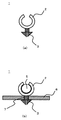
以下に、本発明の第1の実施形態について、図1と共に説明する。図1の(a)は本発明の第1の実施形態にかかる光源支持装置の断面図を示しており、(b)は(a)の光源支持装置を反射板に取り付けるとともに該光源支持装置に光源を支持した場合の断面図を示している。
【0020】
なお、各実施形態においては、光源として蛍光管を用い、被装着板として反射板を用いた場合を例にして説明する。
【0021】
図1を参照して、光源支持装置1は、基体4に、円環状の蛍光管5を支持するための支持部2と、基体4の支持部2配置側とは相対する側に設けられた係止部3とが取り付けられた形状をしている。
【0022】
支持部2は、透明材料から形成され、その断面が円弧の一部を切り欠いた形状に形成されており、切り欠いた個所に蛍光管5を嵌め込むことにより、蛍光管5を支持部2に固定できるようになっている。
【0023】
さらに、係止部3は有色材料から形成されており、その基体4側は反射板6に設けられた貫通孔7より僅かに径が小さい首部3aと、貫通孔7より径が大きい頭部3bが備えられるものである。そして、貫通孔7に係止部3を取り付けたときには、貫通孔7に首部3aが嵌まり込み、頭部3bが反射板6の光源配置側と相対する側の面と当接することにより、光源支持装置1を反射板6から抜け落ちることを防止するものである。
【0024】
また、基体4は、支持部2と同様に透明材料から形成されており、支持部2の台座としての役割を備えるものである。
【0025】
以上のような構成で蛍光管5を光源支持装置1により反射板6に取付け点灯させると、蛍光管5から発せられた光は、反射板6よりも蛍光管5の配置側には放射されるが、反射板6の蛍光管5の配置側とは相対する側に対しては、係止部3が有色に形成されていることにより殆ど光が透過することがなく、上記従来例の課題を解決し得る。
【0026】
しかしながら、図1のごとく、蛍光管5に対して反射板配置側とは相対する側から見たときに係止部3が蛍光管5の背後に隠れない配置であった場合には、有色の係止部の存在する部分のみが暗くなる。したがって、例えば液晶表示装置のバックライト装置のように均一な光を要する場合に、上記の光源支持装置1を用いると、部分的に暗い個所が生じてしまい良好な発光状態とはいえないものとなる虞がある。
【0027】
そこで、この改良例を第2の実施形態として説明する。第2の実施の形態は図2に示すように形成するものである。
【0028】
図2は、(a)は、本発明の第2の実施の形態にかかる光源支持装置の断面図を示しており、(b)は(a)の光源支持装置を反射板に取り付けるとともに該光源支持装置に光源を支持した場合の断面図を示している。
【0029】
説明の重複を避ける為、この第2の実施形態については第1の実施形態と異なる点のみを説明すると、第2の実施形態においては、係止部3が蛍光管5に対して反射板配置側とは相対する側から見たときに蛍光管5の背後に隠れる位置になるよう係止部3と支持部2とが形成されている点で第1の実施形態と相違する。すなわち、基体4を挟んで支持部2が支持する蛍光管5と係止部3とが対向する位置に配置するものとする。
【0030】
このように形成すると、蛍光管5に対して反射板配置側とは相対する側から見たときには有色の係止部が目立たず、例えば液晶表示装置のバックライト装置のように均一な光を要する場合には、部分的に暗い個所が生じることを防止できる。
【0031】
なお、本発明の実施の形態1及び実施の形態2にかかる図1及び図2にはいずれも、支持部2及び係止部3を複数備えた場合について記載しているが、必ずしも複数ある場合に限られるものではなく単数であっても良い。なお、これは以下に示す各実施形態についても同様である。また単数に形成する場合は、図3に示すように、基体4を廃止して支持部2に係止部3を直接取り付ける形態としても良い。
【0032】
次に、第2の実施の形態を照明装置に適用した例について図4を用いて説明する。図4(a)は本発明の照明装置の略正面図を示しており、(b)は(a)略断面図を示している。
【0033】
図4において、照明装置15は、図示しない駆動装置に接続された複数の蛍光管5を第2の実施形態に示した光源支持装置によって反射板6に取り付けたものである。該反射板6は、複数の蛍光管5と対向して配置されると共に、他の部材に照明装置15を固定するための枠21が取り付けられた形状をしており、例えばアルミニウム板材の表面に高反射率の塗装を施したものや、アルミニウムの板材の表面に高反射率のシートを施したものが具体例として挙げられる。
【0034】
上記のように構成して、駆動装置により蛍光管5を点灯すると、蛍光管5から発せられた光は係止部3が有色に形成されていることにより、反射板6の蛍光管5配置側とは相対する方向(図4(b)では矢印Cの方向)に光が透過することがなく、更には、蛍光管5の係止部3とは相対する側(つまり、図4(b)では矢印Bの方向)から蛍光管5を見た際に係止部3が蛍光管5に隠れることになる。従って、有色に成型された部分が蛍光管5の背後にあることから反射率の低い暗い点が無く、照明装置として斑の少ない均一な発光のものを提供することが可能である。
【0035】
なお、上記の第1の実施の形態及び第2の実施の形態にいう、係止部3と基体4との色分けの境界は必ずしも明確でなくても良く、更には図5に示すように基体4の一部が係止部3と同様に有色であっても良い。また、このときであっても、有色に成型された部分が、蛍光管5の係止部3とは相対する側から蛍光管5を見た際に蛍光管5に隠れるよう、基体4に対して蛍光管5と有色に成型された部分とを対向させ配置すると、上記と同様に斑の少ない均一な発光とすることができる。
【0036】
以上には、光源支持装置を複数色を一体に成型した場合の例について記載したが、同様の効果を有する構成は一体的に成型した場合に限られるものではない。
【0037】
次に、複数色を一体的に成型しない場合の実施形態について第3、第4及び第5の実施形態を用いて説明する。
【0038】
第3の実施形態は図6に示すように構成されるものである。図6の(a)は本発明の第3の実施の形態にかかる光源支持装置の断面図を示しており、(b)は(a)の光源支持装置を反射板に取り付けるとともに該光源支持装置に光源を支持した場合の断面図を示している。
【0039】
説明の重複を避ける為、この第3の実施形態については第2の実施形態と異なる点のみを説明すると、その相違点とは、第2の実施形態では係止部3を有色にて成型したが、第3の実施形態では係止部3を支持部2及び基体4と同様に透明に形成し、該透明に成型した係止部3の蛍光管5の配置側とは相対する側の面に有色の皮膜13を施した点である。なお、この皮膜13は具体的には、有色の材料による塗装、メッキ、有色テープ類の貼付等の手段により形成することができる。
【0040】
また、図7の(a)は本発明の第4の実施の形態にかかる光源支持装置の断面図を示しており、(b)は(a)の光源支持装置を反射板に取り付けるとともに該光源支持装置に光源を支持した場合の断面図を示している。
【0041】
説明の重複を避ける為、この第4の実施形態についても第2の実施形態と異なる点のみを説明すると、その相違点とは、第2の実施形態では係止部3を有色にて成型したが、第4の実施形態では係止部3を支持部2及び基体4と同様に透明に形成するとともに係止部3を反射板6に設けた貫通孔7より小さい外径を備えた螺子部14を形成し、反射板6の貫通孔7に係止部3を挿通させた後、少なくとも貫通孔7の外周より大きい形状に形成された有色のカバー体16を螺合することにより光源支持装置2を反射板6に取り付けている点である。
【0042】
カバー体16の具体例としては、有色に成型された樹脂材料や金属材料によって形成することができる。
【0043】
また、図8の(a)は本発明の第5の実施の形態にかかる光源支持装置の断面図を示しており、(b)は(a)の光源支持装置を反射板に取り付けるとともに該光源支持装置に光源を支持した場合の断面図を示している。
【0044】
説明の重複を避ける為、この第5の実施形態についても第2の実施形態と異なる点のみを説明すると、その相違点とは、第2の実施形態では係止部3を有色にて成型したが、第5の実施形態では係止部3を廃止するとともに、第2の実施形態であれば基体4の係止部3が取り付けられていた位置に被係止部17を設け、反射板6の貫通孔7に有色の係止手段18を挿通させた後、係止手段18を被係止部17に係止させるものである。
【0045】
上記被係止部17及び係止手段18の具体例としては、被係止部17を螺子孔、係止手段18を有色(金属でも樹脂でも良い)の螺子とした場合が挙げられるが、この例に限られるものではない。
【0046】
以上のように、第3、第4及び第5の実施形態のように形成しても、第2の実施形態と同様に、反射板6の蛍光管5の配置側とは相対する側に光が透過することを防止できるとともに、例えば液晶表示装置のバックライト装置のように均一な光を要する場合に、部分的に暗い個所が生じることを防止できる。従って、上記に説明した第2の実施形態を照明装置に適用した例に、第3、第4及び第5の実施形態を適用しても、照明装置として斑の少ない均一な発光のものを提供することが可能である。また、複数色を一体に形成しないため製造容易である。
【0047】
なお、第3、第4及び第5の実施形態については、第2の実施形態の一部に変更を加えた例について示したが、同様の変更を第1の実施形態に適用することもできる。この場合も、第1の実施形態と同様に反射板6の蛍光管5の配置側とは相対する側に光が透過することを防止できる。
【0048】
以上に説明した、第1から第5の実施形態には更なる改良を加えることが可能である。すなわち、例えば液晶表示装置のバックライト装置のように均一な光を要する照明装置では、蛍光管5の反射板6とは相対する側に、蛍光管5から発せられた光を面状の均一な発光とすべく光を拡散させる拡散板7(図10参照)を配置する場合があるが、この拡散板7は、蛍光管5の熱や湿気の影響を受けて反る場合がある。この反り幅が大きいと、拡散板7の機能である光を拡散する効果が減殺され、面状の均一な発光状態でなくなるという問題がおきる。
【0049】
そこで、拡散板7の反りを防止する手段が必要となるが、この反りを防止する手段を第1から第5の実施形態に一体的に設けることにより、部品点数を増加させることなく拡散板7の反りを防止できる。
【0050】
この場合の実施形態として、第2の実施形態を改良した例を第6の実施形態として図9と共に説明する。図9の(a)は本発明の第6の実施の形態にかかる光源支持装置の断面図を示しており、(b)は(a)の光源支持装置を反射板に取り付けるとともに該光源支持装置に光源を支持した場合の断面図を示している。
【0051】
説明の重複を避ける為、この第6の実施形態については第2の実施形態に加えた改良点のみを説明すると、拡散板7の反りを防止する手段として、基体4の支持部2配置側の面から、支持部2により保持される蛍光管5の基体4とは最も相対する側より突出した略円錐状の突起8を形成している点である。
【0052】
この光源支持装置を照明装置15に用いた場合には図10のように形成される。図10は、照明装置15の断面図を示している。
【0053】
図10については、図4に示した第2の実施形態を照明装置15に適用した例と相違する点を述べると、その相違点は、第2の実施形態に代えて第6の実施形態を適用した点、及び蛍光管5と対向する反射板6の配置側とは相対する側に光を拡散する拡散板7を設けた点である。
【0054】
以上のように照明装置15を形成することにより、反射板6の蛍光管5側とは相対する側に光が透過することがなく、かつ拡散板7が蛍光管5側に反っても突起8によってその反りが規制される照明装置を安価に形成することができる。
【0055】
さらに、この照明装置15を液晶表示装置20に用いた例を図11に示す。図11は、図10に記載した照明装置に加えて、拡散板7の反射板6配置側とは相対する側に設けた液晶パネル10と、液晶パネル10の駆動装置(図示なし)と、液晶パネル10と拡散板7との間に配置した光学シート9とを枠体11に保持させたものである。
【0056】
なお、上記の光学シート9、液晶パネル10、枠体11については周知の技術を適宜組合せて適用できるものであるため、特に説明をしない。
【0057】
以上のように形成することにより、反射板6の蛍光管5側とは相対する側に光が透過するという問題がないのみならず、液晶パネル10の表示には有色の係止部3が原因となる輝度斑が発生せず、かつ、拡散板7の反りを原因とする輝度斑が発生することがないため、長時間、輝度斑のない良好な発光状態の液晶表示装置20を提供することができる。
【0058】
以上の説明では、光源として蛍光管5を用いた場合について説明したが、例えばLED等の他の光源を用いた場合でも、上記の光源支持装置は同様の効果を発揮できる。また、各実施形態に記載した光源支持装置はいずれも照明装置及び液晶表示装置に適用できるものであることはいうまでもない。
【0059】
そして、支持部2の例については、支持部2は、透明材料から形成され、その断面が円弧の一部を切り欠いた形状についてのみ説明をしているが、光源の形状に合わせて適宜変更を加えることが可能であることは明らかである。また、その他の構成についてもこの例に限らず設計に応じて適宜変更を加え得ることは勿論である。
【0060】
【発明の効果】
以上説明した通り、本発明によれば、光源から発せられる光が被装着板の光源とは相対する側に透過することを防止することができる。
【0061】
そして、前記係止部は、前記支持部によって支持される光源とは対向した位置に配置されるものとする。このように構成によると、前記光源を被装着板とは相対する側から見た場合に、光源の背後に係止部が配置されることになるため、例えば係止部を有色に形成した場合であっても係止部が目立つことがない。
【0062】
また、基体と、該基体の一側に設けられた光源を支持する支持部と、前記基体の他側に設けられた被係止部とを備え、かつ透明材料から形成された光源支持装置であって、前記被係止部に、被装着板に設けられた貫通孔を介して有色の係止手段を装着することにより、前記被装着板に前記基体を係止する光源支持装置とすると、光源支持装置を複数色に成型せずともよく、さらには係止部を予め基体に一体に形成しないため容易に光源支持装置を形成することが可能である。
【0063】
さらに、この場合においても、前記被係止部は、前記支持部によって支持される光源とは対向した位置に配置されるものとすると、前記光源を被装着板とは相対する側から見た場合に、光源の背後に係止部が配置されることになるため、例えば係止部を有色に形成した場合であっても係止部が目立つことがない。
【0064】
そして、光源支持装置と、前記光源側に前記光源よりも突出する突起を一体に設けたことを特徴とする光源支持装置とする。この構成によれば、光源に対して前記係止部とは相対する側に配置される部材が光源側に反るような場合であっても、突起によりその反り量を規制することが可能である。
【0065】
さらに、光源支持装置と、該光源支持装置の前記支持部にて支持される光源と、前記被装着板として前記光源から発せられる光を反射する反射板とを備えた照明装置とする。この構成によれば、光源に対して反射板配置側とは相対する側から照明装置を見たときに、反射板の背後より光が漏洩することがない。
【0066】
また、光源支持装置と、該光源支持装置の前記支持部にて支持される光源と、前記被装着板として前記光源から発せられる光を反射する反射板と、前記光源に対して前記反射板の配置された方向とは相対する方向に設けられ光源から発せられた光を拡散させ透過する拡散板と、前記光源支持装置に一体に備えられ前記拡散板に向かって突設された突起と、を備えた照明装置とする。この構成によれば、拡散板が反った場合でもその反り量を規制して、均一な面状の発光が可能な照明装置を提供することができる。
【0067】
さらにまた、上記の照明装置と、前記拡散板の光源配置側とは相対する側に設けられた液晶パネルとを有することを特徴とする液晶表示装置とする。この構成によれば、反射板の光源配置側とは相対する側に光を透過することがないのみならず、拡散板の反りを原因とする輝度斑が発生することがないため、液晶表示装置の表示面から発せられる輝度を均一にすることができる。
【図面の簡単な説明】
【図1】(a)は、本発明の第1の実施の形態にかかる光源支持装置の断面図。
(b)は、(a)の光源支持装置を反射板に取り付けるとともに該光源支持装置に光源を支持した場合の断面図。
【図2】(a)は、本発明の第2の実施の形態にかかる光源支持装置の断面図。
(b)は、(a)の光源支持装置を反射板に取り付けるとともに該光源支持装置に光源を支持した場合の断面図。
【図3】第2の実施形態の支持部及び係止部を単数にした場合の断面図。
【図4】(a)は本発明の照明装置の略正面図。
(b)は(a)略断面図。
【図5】第2の実施形態の変形態様を示す断面図。
【図6】(a)は本発明の第3の実施の形態にかかる光源支持装置の断面図。
(b)は(a)の光源支持装置を反射板に取り付けるとともに該光源支持装置に光源を支持した場合の断面図。
【図7】(a)は本発明の第4の実施の形態にかかる光源支持装置の断面図。
(b)は(a)の光源支持装置を反射板に取り付けるとともに該光源支持装置に光源を支持した場合の断面図。
【図8】(a)は本発明の第5の実施の形態にかかる光源支持装置の断面図。
(b)は(a)の光源支持装置を反射板に取り付けるとともに該光源支持装置に光源を支持した場合の断面図。
【図9】(a)は本発明の第6の実施の形態にかかる光源支持装置の断面図。
(b)は(a)の光源支持装置を反射板に取り付けるとともに該光源支持装置に光源を支持した場合の断面図。
【図10】第6の実施形態を照明装置に用いた場合の断面図。
【図11】本発明の第6の実施形態を液晶表示装置に用いた場合の断面図。
【図12】従来技術にかかる光源支持装置の装着図。
【符号の説明】
1 光源支持装置
2 支持部
3 係止部
4 基体
5 光源(蛍光管)
6 被装着板(反射板)
7 拡散板
8 突起
9 光学シート
10 液晶パネル
15 照明装置
20 液晶表示装置[0001]
BACKGROUND OF THE INVENTION
The present invention relates to a device that supports a light source, and is used, for example, in an illumination device used as a backlight device of a liquid crystal display device.
[0002]
[Prior art]
In recent years, very large liquid crystal display devices have been developed. In such a large liquid crystal display device, a backlight having a fluorescent tube arranged in parallel with the liquid crystal panel is used.
[0003]
In order to form a large-sized liquid crystal display device, the length of the fluorescent tube used for the backlight must inevitably be increased. Fluorescent tubes have been used as light sources. For this reason, if the fluorescent tubes arranged in parallel are only supported at both ends, there is a problem that the support strength of the fluorescent tubes is not sufficient and deformation or breakage occurs.
[0004]
Therefore, in order to improve the support strength of the fluorescent tube, a light source support device that supports the intermediate portion of the fluorescent tube is required. Examples of the light source support device include those described in JP-A-2001-210126. The technique described in this publication will be described with reference to FIG.
[0005]
FIG. 12 is a mounting view of the light
[0006]
The light
[0007]
[Problems to be solved by the invention]
However, the light
[0008]
[Means for Solving the Problems]
Therefore, in order to solve the above problem, the present invention includes a support portion that supports a light source, and a locking portion, and by mounting the locking portion in a through hole provided in a mounting plate, A light source support device for attaching a light source supported by a support part to the mounted plate, wherein the support part is formed of a transparent material and the locking part is formed of a colored material. Let it be a support device. By forming in this way, it is possible to prevent the light emitted from the light source from being transmitted to the side of the mounted plate facing the light source.
[0009]
Further, the light source supported by the support part is mounted on the mounting plate by mounting the locking part in a through-hole provided in the mounting plate. A light source support device attached to the light source, wherein the light source support device is formed transparent, and light emitted from the light source is transmitted through the through hole to a side opposite to the light source side of the mounted plate. The light source supporting device is provided with a light transmission preventing means for preventing the light. By forming in this way, it is possible to prevent the light emitted from the light source from being transmitted to the side of the mounted plate facing the light source.
[0010]
At this time, since the manufacturing process may be complicated if the members of a plurality of colors are integrally formed, the light transmission preventing means is provided with a colored film on the surface facing the light source arrangement side of the locking portion. Shall be applied.
[0011]
Similarly, the light transmission preventing means includes a cover body that covers a portion of the locking portion that protrudes from the mounted plate when the light source support device is mounted on the mounted plate. If formed in such a manner, the light source support device may be formed in a single color and can be manufactured at a low cost.
This is a light source support device having a support portion for supporting a light source and a locking portion, wherein the light source support device is formed transparent, and the locking portion is formed in a through-hole provided in a mounting plate. A light source support device mounted on the mounted plate by covering a portion of the locking portion that protrudes from the mounted plate with a colored locking means when mounted. Is the same.
[0012]
And the said latching | locking part shall be arrange | positioned in the position facing the light source supported by the said support part. If formed in this way, the colored locking portion is inconspicuous because it is not visible from the light source side, and when this light source support device is used for a lighting device that requires a uniform light emission, The resulting brightness spots can be prevented.
[0013]
Furthermore, a light source support device comprising a base, a support part for supporting a light source provided on one side of the base, and a locked part provided on the other side of the base, and formed from a transparent material. The locking means is locked to the locked portion through a through-hole provided in the mounted plate , so that the base is mounted on the mounted plate, and light from the light source is A light source support device is provided that prevents the light from passing through the through hole . By forming in this way, it is possible to prevent the light emitted from the light source from being transmitted to the side of the mounted plate facing the light source.
[0014]
The mounting hole is arranged at a position facing the light source supported by the support portion. If formed in this way, the colored locking means is inconspicuous because it is not visible from the light source side, and when this light source support device is used in a lighting device that requires a uniform light emission in the surface, The resulting brightness spots can be prevented.
[0015]
In the light source support device, the light source support device is characterized in that a protrusion protruding from the light source is integrally provided on the light source side. When formed in this way, when the optical member such as a diffuser plate is disposed on the light source support device on the side facing the light reflector, the amount of warpage of the optical member can be regulated by the protrusion. .
[0016]
Furthermore, it is set as an illuminating device provided with a light source support apparatus, the light source supported by the said support part of this light source support apparatus, and the reflecting plate which reflects the light emitted from the said light source as said to-be-mounted board.
[0017]
A light source support device; a light source supported by the support portion of the light source support device; a reflector that reflects light emitted from the light source as the mounted plate; and A diffusion plate that is provided in a direction opposite to the arranged direction and diffuses and transmits the light emitted from the light source; and a protrusion that is provided integrally with the light source support device and protrudes toward the diffusion plate. It is set as the illuminating device characterized by having provided.
[0018]
And it is set as the liquid crystal display device characterized by having the said illuminating device and a liquid crystal panel .
[0019]
DETAILED DESCRIPTION OF THE INVENTION
Below, the 1st Embodiment of this invention is described with FIG. FIG. 1A shows a cross-sectional view of a light source support device according to a first embodiment of the present invention, and FIG. 1B shows the light source support device of FIG. Sectional drawing at the time of supporting a light source is shown.
[0020]
In each embodiment, a case where a fluorescent tube is used as a light source and a reflecting plate is used as a mounted plate will be described as an example.
[0021]
Referring to FIG. 1, a light
[0022]
The
[0023]
Further, the locking
[0024]
The
[0025]
When the
[0026]
However, as shown in FIG. 1, when the locking
[0027]
Therefore, this improved example will be described as a second embodiment. The second embodiment is formed as shown in FIG.
[0028]
FIG. 2A is a cross-sectional view of a light source support device according to a second embodiment of the present invention, and FIG. 2B is a view in which the light source support device of FIG. Sectional drawing at the time of supporting a light source on the support apparatus is shown.
[0029]
In order to avoid duplication of explanation, only the points different from the first embodiment will be described in the second embodiment. In the second embodiment, the locking
[0030]
When formed in this way, the colored locking portion is not conspicuous when viewed from the side opposite to the reflecting plate arrangement side with respect to the
[0031]
1 and 2 according to the first and second embodiments of the present invention describe the case where a plurality of
[0032]
Next, the example which applied 2nd Embodiment to the illuminating device is demonstrated using FIG. FIG. 4A shows a schematic front view of the lighting device of the present invention, and FIG. 4B shows a schematic sectional view of FIG.
[0033]
In FIG. 4, the illuminating
[0034]
When the
[0035]
Note that the color separation boundary between the locking
[0036]
In the above, an example in which the light source support device is integrally molded with a plurality of colors has been described. However, the configuration having the same effect is not limited to the case of integrally molding.
[0037]
Next, embodiments in which a plurality of colors are not integrally molded will be described using third, fourth, and fifth embodiments.
[0038]
The third embodiment is configured as shown in FIG. FIG. 6A shows a cross-sectional view of a light source support device according to a third embodiment of the present invention, and FIG. 6B shows the light source support device of FIG. Sectional drawing at the time of supporting a light source is shown.
[0039]
In order to avoid duplication of explanation, only the differences from the second embodiment will be described for the third embodiment. The difference is that the locking
[0040]
FIG. 7A shows a cross-sectional view of the light source support device according to the fourth embodiment of the present invention, and FIG. 7B shows the light source support device of FIG. Sectional drawing at the time of supporting a light source on the support apparatus is shown.
[0041]
In order to avoid duplication of explanation, only the differences of the fourth embodiment from the second embodiment will be described. The difference is that in the second embodiment, the locking
[0042]
As a specific example of the
[0043]
FIG. 8A shows a cross-sectional view of the light source support device according to the fifth embodiment of the present invention, and FIG. 8B shows the light source support device of FIG. Sectional drawing at the time of supporting a light source on the support apparatus is shown.
[0044]
In order to avoid duplication of explanation, only the differences of the fifth embodiment from the second embodiment will be described. The difference is that in the second embodiment, the locking
[0045]
Specific examples of the locked
[0046]
As described above, even if formed as in the third, fourth, and fifth embodiments, light is applied to the side of the
[0047]
In addition, about the 3rd, 4th and 5th embodiment, although the example which added the change to a part of 2nd Embodiment was shown, the same change can also be applied to 1st Embodiment. . Also in this case, similarly to the first embodiment, it is possible to prevent light from being transmitted to the side of the
[0048]
Further improvements can be added to the first to fifth embodiments described above. That is, for example, in an illuminating device that requires uniform light, such as a backlight device of a liquid crystal display device, the light emitted from the
[0049]
Therefore, a means for preventing the warp of the
[0050]
As an embodiment in this case, a modified example of the second embodiment will be described as a sixth embodiment with reference to FIG. FIG. 9A shows a cross-sectional view of a light source support device according to a sixth embodiment of the present invention, and FIG. 9B shows a state in which the light source support device of FIG. Sectional drawing at the time of supporting a light source is shown.
[0051]
In order to avoid duplication of explanation, only the improvements added to the second embodiment will be described for the sixth embodiment. As a means for preventing the
[0052]
When this light source support device is used for the
[0053]
With regard to FIG. 10, a difference from the example in which the second embodiment shown in FIG. 4 is applied to the
[0054]
By forming the
[0055]
Further, an example in which the
[0056]
The optical sheet 9, the
[0057]
By forming as described above, there is no problem that light is transmitted to the side of the reflecting
[0058]
In the above description, the case where the
[0059]
And about the example of the
[0060]
【The invention's effect】
As described above, according to the present invention, it is possible to prevent light emitted from the light source from being transmitted to the side of the mounted plate facing the light source.
[0061]
And the said latching | locking part shall be arrange | positioned in the position facing the light source supported by the said support part. According to this configuration, when the light source is viewed from the side facing the mounted plate, the locking portion is disposed behind the light source. For example, when the locking portion is colored Even so, the locking portion does not stand out.
[0062]
And a light source support device comprising a base, a support part for supporting a light source provided on one side of the base, and a locked part provided on the other side of the base, and formed of a transparent material. And, by attaching a colored locking means to the locked portion through a through hole provided in the mounted plate, a light source support device that locks the base on the mounted plate, The light source support device does not have to be molded into a plurality of colors, and furthermore, since the locking portion is not formed integrally with the base in advance, the light source support device can be easily formed.
[0063]
Further, in this case as well, when the locked portion is disposed at a position facing the light source supported by the support portion, the light source is viewed from the side facing the mounting plate. In addition, since the locking portion is disposed behind the light source, for example, even when the locking portion is formed in a colored manner, the locking portion does not stand out.
[0064]
And it is set as the light source support apparatus characterized by integrally providing the light source support apparatus and the protrusion which protrudes rather than the said light source in the said light source side. According to this configuration, even when a member disposed on the side facing the locking portion with respect to the light source warps to the light source side, the amount of warpage can be regulated by the protrusion. is there.
[0065]
Furthermore, it is set as the illuminating device provided with the light source support apparatus, the light source supported by the said support part of this light source support apparatus, and the reflecting plate which reflects the light emitted from the said light source as said to-be-mounted board. According to this configuration, when the illumination device is viewed from the side opposite to the reflection plate arrangement side with respect to the light source, light does not leak from behind the reflection plate.
[0066]
A light source support device; a light source supported by the support portion of the light source support device; a reflector that reflects light emitted from the light source as the mounted plate; and A diffusion plate that is provided in a direction opposite to the arranged direction and diffuses and transmits the light emitted from the light source; and a protrusion that is provided integrally with the light source support device and protrudes toward the diffusion plate. It is set as the provided lighting device. According to this configuration, it is possible to provide an illuminating device that can emit light evenly by regulating the amount of warpage even when the diffusion plate is warped.
[0067]
Furthermore, the liquid crystal display device includes the above-described illumination device and a liquid crystal panel provided on a side of the diffusion plate facing the light source arrangement side. According to this configuration, the liquid crystal display device not only transmits light to the side opposite to the light source arrangement side of the reflection plate but also does not generate luminance spots caused by warpage of the diffusion plate. The luminance emitted from the display surface can be made uniform.
[Brief description of the drawings]
FIG. 1A is a sectional view of a light source support apparatus according to a first embodiment of the present invention.
(B) is sectional drawing at the time of attaching a light source support apparatus of (a) to a reflecting plate, and supporting a light source to this light source support apparatus.
FIG. 2A is a sectional view of a light source support device according to a second embodiment of the present invention.
(B) is sectional drawing at the time of attaching a light source support apparatus of (a) to a reflecting plate, and supporting a light source to this light source support apparatus.
FIG. 3 is a cross-sectional view in the case where a single supporting portion and locking portion are used in the second embodiment.
FIG. 4A is a schematic front view of the illumination device of the present invention.
(B) is (a) schematic sectional drawing.
FIG. 5 is a sectional view showing a modification of the second embodiment.
FIG. 6A is a cross-sectional view of a light source support device according to a third embodiment of the present invention.
(B) is sectional drawing at the time of attaching a light source support apparatus of (a) to a reflecting plate, and supporting a light source to this light source support apparatus.
FIG. 7A is a sectional view of a light source support apparatus according to a fourth embodiment of the present invention.
(B) is sectional drawing at the time of attaching a light source support apparatus of (a) to a reflecting plate, and supporting a light source to this light source support apparatus.
FIG. 8A is a sectional view of a light source support device according to a fifth embodiment of the present invention.
(B) is sectional drawing at the time of attaching a light source support apparatus of (a) to a reflecting plate, and supporting a light source to this light source support apparatus.
FIG. 9A is a sectional view of a light source support apparatus according to a sixth embodiment of the present invention.
(B) is sectional drawing at the time of attaching a light source support apparatus of (a) to a reflecting plate, and supporting a light source to this light source support apparatus.
FIG. 10 is a cross-sectional view when the sixth embodiment is used in a lighting device.
FIG. 11 is a cross-sectional view when a sixth embodiment of the present invention is used in a liquid crystal display device.
FIG. 12 is a mounting view of a light source support device according to the prior art.
[Explanation of symbols]
DESCRIPTION OF
6 Mounted plate (reflector)
7
Claims (13)
前記支持部を透明材にて形成するとともに、前記係止部を有色材にて形成したことを特徴とする光源支持装置。A light source supported by the support unit is attached to the mounted plate by mounting the locking unit in a through-hole provided in the mounted plate. A light source support device,
The light source support device, wherein the support portion is formed of a transparent material, and the locking portion is formed of a colored material.
前記光源支持装置を透明に形成するとともに、前記光源から発せられる光が、前記貫通孔を介して前記被装着板の光源側とは相対する側へ透過することを防止する光透過防止手段を設けたことを特徴とする光源支持装置。A light source supported by the support unit is attached to the mounted plate by mounting the locking unit in a through-hole provided in the mounted plate. A light source support device,
The light source support device is formed transparent, and light transmission preventing means is provided for preventing light emitted from the light source from being transmitted through the through hole to a side opposite to the light source side of the mounted plate. A light source support device characterized by that.
前記光源支持装置を透明で形成するとともに、前記係止部を被装着板に設けられた貫通孔に装着したときに前記係止部のうち前記被装着板より突出する部分に対して、有色の係止手段を被覆することにより、前記被装着板に装着されることを特徴とする光源支持装置。The light source support device is formed transparent, and when the locking portion is mounted in a through-hole provided in the mounted plate, a colored portion of the locking portion protrudes from the mounted plate. A light source support device, wherein the light source support device is mounted on the mounted plate by covering a locking means.
被装着板に設けられた貫通孔を介して前記被係止部に係止手段を係止することにより、前記基体を前記被装着板に装着するとともに、前記光源からの光が前記貫通孔を透過するのを防止することを特徴とする光源支持装置。A light source support device comprising a base, a support part for supporting a light source provided on one side of the base, and a locked part provided on the other side of the base, and formed from a transparent material. ,
By locking a locking means to the locked portion through a through hole provided in the mounted plate , the base is mounted on the mounted plate, and light from the light source passes through the through hole. A light source support device characterized by preventing transmission .
前記光源側に前記光源よりも突出する突起を一体に設けたことを特徴とする光源支持装置。In the light source support device according to any one of claims 1 to 8 ,
A light source support device, wherein a protrusion protruding from the light source is provided integrally on the light source side.
Priority Applications (10)
| Application Number | Priority Date | Filing Date | Title |
|---|---|---|---|
| JP2002152180A JP3616612B2 (en) | 2002-05-27 | 2002-05-27 | Light source support device, illumination device, and liquid crystal display device |
| ES03730584T ES2367301T3 (en) | 2002-05-27 | 2003-05-22 | LIGHT SOURCE SUPPORT DEVICE, LIGHTING GLASS DEVICE AND LIQUID GLASS DISPLAY. |
| AU2003242398A AU2003242398A1 (en) | 2002-05-27 | 2003-05-22 | Light source support device, lighting device, and liquid crystal display |
| EP03730584A EP1515083B1 (en) | 2002-05-27 | 2003-05-22 | Light source support device, lighting device, and liquid crystal display |
| CNA03812176XA CN1656338A (en) | 2002-05-27 | 2003-05-22 | Light source support device, lighting device, and liquid crystal display |
| US10/515,498 US20050225992A1 (en) | 2002-05-27 | 2003-05-22 | Light source support device, lighting device, and liquid crystal display |
| PCT/JP2003/006403 WO2003100317A1 (en) | 2002-05-27 | 2003-05-22 | Light source support device, lighting device, and liquid crystal display |
| KR1020047019125A KR100693979B1 (en) | 2002-05-27 | 2003-05-22 | Light source support device, lighting device and liquid crystal display device |
| MYPI20031933A MY131260A (en) | 2002-05-27 | 2003-05-26 | Light source support, lighting apparatus, and a liquid crystal display |
| TW092114265A TWI247862B (en) | 2002-05-27 | 2003-05-27 | Light source support, lighting apparatus, and liquid crystal |
Applications Claiming Priority (1)
| Application Number | Priority Date | Filing Date | Title |
|---|---|---|---|
| JP2002152180A JP3616612B2 (en) | 2002-05-27 | 2002-05-27 | Light source support device, illumination device, and liquid crystal display device |
Related Child Applications (1)
| Application Number | Title | Priority Date | Filing Date |
|---|---|---|---|
| JP2004267655A Division JP2005019420A (en) | 2004-09-15 | 2004-09-15 | Backlight device and liquid crystal display device |
Publications (3)
| Publication Number | Publication Date |
|---|---|
| JP2003346541A JP2003346541A (en) | 2003-12-05 |
| JP3616612B2 true JP3616612B2 (en) | 2005-02-02 |
| JP2003346541A5 JP2003346541A5 (en) | 2005-06-16 |
Family
ID=29561271
Family Applications (1)
| Application Number | Title | Priority Date | Filing Date |
|---|---|---|---|
| JP2002152180A Expired - Fee Related JP3616612B2 (en) | 2002-05-27 | 2002-05-27 | Light source support device, illumination device, and liquid crystal display device |
Country Status (10)
| Country | Link |
|---|---|
| US (1) | US20050225992A1 (en) |
| EP (1) | EP1515083B1 (en) |
| JP (1) | JP3616612B2 (en) |
| KR (1) | KR100693979B1 (en) |
| CN (1) | CN1656338A (en) |
| AU (1) | AU2003242398A1 (en) |
| ES (1) | ES2367301T3 (en) |
| MY (1) | MY131260A (en) |
| TW (1) | TWI247862B (en) |
| WO (1) | WO2003100317A1 (en) |
Families Citing this family (44)
| Publication number | Priority date | Publication date | Assignee | Title |
|---|---|---|---|---|
| TW200523628A (en) * | 2004-01-06 | 2005-07-16 | Hannstar Display Corp | Upright backlight module |
| JP4155969B2 (en) | 2004-01-14 | 2008-09-24 | シャープ株式会社 | Lighting device for display device |
| DE102004003123A1 (en) * | 2004-01-15 | 2005-08-04 | Gottlieb Binder Gmbh & Co. Kg | Adhesive closure part with illuminant and method for producing such an adhesive closure part |
| JP4597535B2 (en) * | 2004-01-22 | 2010-12-15 | 株式会社 日立ディスプレイズ | Liquid crystal display |
| KR101001973B1 (en) * | 2004-04-12 | 2010-12-17 | 삼성전자주식회사 | Backlight Assembly and Display Device Having Same |
| TWI246575B (en) | 2004-06-08 | 2006-01-01 | Chi Lin Technology Co Ltd | Lamp tube retaining and supporting structure for direct type backlight module |
| JP4072519B2 (en) * | 2004-06-18 | 2008-04-09 | シャープ株式会社 | Lighting device for display device |
| KR101102018B1 (en) * | 2004-06-28 | 2012-01-04 | 엘지디스플레이 주식회사 | Backlight unit |
| TWI335454B (en) * | 2004-07-13 | 2011-01-01 | Chi Mei Optoelectronics Corp | Positioning apparatus for preventing deformation of diffuser plate of the backlight unit |
| KR101041053B1 (en) | 2004-07-21 | 2011-06-13 | 삼성전자주식회사 | Back light assembly and liquid crystal display device having same |
| JP2006078952A (en) * | 2004-09-13 | 2006-03-23 | Nifco Inc | Clip |
| KR20060047025A (en) | 2004-11-12 | 2006-05-18 | 삼성전자주식회사 | Backlight assembly with improved support and flat panel display with same |
| JP4598007B2 (en) * | 2004-11-30 | 2010-12-15 | シャープ株式会社 | Lamp holder, backlight device using the same, display device using the same, and liquid crystal display device using the backlight device |
| EP1818608B1 (en) * | 2004-11-30 | 2008-12-17 | Sharp Kabushiki Kaisha | Lamp holding apparatus, backlight device for display device including same, display devise including same and liquid crystal display device including backlight device for display devise |
| JPWO2006059464A1 (en) * | 2004-11-30 | 2008-06-05 | シャープ株式会社 | Lamp holder, illumination device for display device using the same, display device using the same, and liquid crystal display device using the illumination device for display device |
| US7677757B2 (en) | 2004-11-30 | 2010-03-16 | Sharp Kabushiki Kaisha | Lamp holder, backlight device using the same, and display using the same |
| KR101033095B1 (en) | 2004-12-31 | 2011-05-06 | 엘지디스플레이 주식회사 | Lamp fixing device and liquid crystal display device having same |
| KR101250782B1 (en) | 2004-12-31 | 2013-04-04 | 엘지디스플레이 주식회사 | Backlight assembly |
| US20080019152A1 (en) * | 2005-01-06 | 2008-01-24 | Sharp Kabushiki Kaisha | Light-Source Holder, Illumination Device For Display Device, And Display Device |
| KR20060089434A (en) | 2005-02-04 | 2006-08-09 | 삼성전자주식회사 | Back light assembly and display device having same |
| KR101129427B1 (en) * | 2005-03-09 | 2012-06-12 | 삼성전자주식회사 | Back light assembly and display device having the same |
| CN100371788C (en) * | 2005-04-14 | 2008-02-27 | 友达光电股份有限公司 | backlight module of flat panel display |
| JP4648070B2 (en) | 2005-04-27 | 2011-03-09 | 株式会社 日立ディスプレイズ | Display device |
| JP3872810B1 (en) * | 2005-08-12 | 2007-01-24 | シャープ株式会社 | Light source control device, illumination device, and liquid crystal display device |
| JP2006147590A (en) * | 2005-09-06 | 2006-06-08 | Sharp Corp | Backlight device |
| KR101267527B1 (en) * | 2005-09-08 | 2013-05-23 | 엘지디스플레이 주식회사 | fluorescent lamp guide holder for liquid crystal display device, back light assembly and liquid crystal display module using thereof |
| US20100142186A1 (en) * | 2005-09-09 | 2010-06-10 | Sharp Kabushiki Kaisha | Light source holding device, illumination device, and display device |
| KR20070039698A (en) * | 2005-10-10 | 2007-04-13 | 삼성전자주식회사 | Back light assembly and display device having same |
| JP4896669B2 (en) * | 2005-11-02 | 2012-03-14 | 三星電子株式会社 | Backlight assembly, liquid crystal display device having the same, and method of manufacturing lamp fixing member |
| JP4162681B2 (en) * | 2005-11-29 | 2008-10-08 | シャープ株式会社 | Backlight and liquid crystal display device |
| JP4140639B2 (en) * | 2006-05-12 | 2008-08-27 | 船井電機株式会社 | Liquid crystal display |
| JP3992726B1 (en) * | 2006-06-26 | 2007-10-17 | シャープ株式会社 | Clip and light source device |
| JP4544221B2 (en) | 2006-09-05 | 2010-09-15 | 船井電機株式会社 | Lamp holder and lamp holder mounting structure |
| US7510318B2 (en) * | 2007-03-12 | 2009-03-31 | Hannstar Display Corp. | Fastening apparatus for a backlight assembly |
| CN100480576C (en) * | 2007-07-04 | 2009-04-22 | 友达光电股份有限公司 | Lamp tube supporting structure |
| US20100232140A1 (en) * | 2007-09-28 | 2010-09-16 | Sharp Kabushiki Kaisha | Lamp holder, backlight unit and display device |
| JP5254591B2 (en) * | 2007-10-25 | 2013-08-07 | 株式会社ジャパンディスプレイイースト | Liquid crystal display |
| KR101445734B1 (en) * | 2007-12-07 | 2014-10-01 | 삼성전자 주식회사 | Liquid Crystal Display |
| KR20090059995A (en) * | 2007-12-07 | 2009-06-11 | 삼성전자주식회사 | LCD Display |
| RU2460105C2 (en) * | 2008-04-04 | 2012-08-27 | Шарп Кабусики Кайся | Liquid crystal display backlight |
| US20100321926A1 (en) * | 2008-04-10 | 2010-12-23 | Sharp Kabushiki Kaisha | Backlight for liquid crystal display |
| WO2010061665A1 (en) * | 2008-11-28 | 2010-06-03 | シャープ株式会社 | Illuminating device, display device and television receiver |
| WO2010070950A1 (en) * | 2008-12-18 | 2010-06-24 | シャープ株式会社 | Illumination device, display device, and television reception device |
| JP2019160688A (en) * | 2018-03-15 | 2019-09-19 | シャープ株式会社 | Lighting device and display device including the same |
Family Cites Families (7)
| Publication number | Priority date | Publication date | Assignee | Title |
|---|---|---|---|---|
| GB469239A (en) * | 1937-03-16 | 1937-07-21 | Patent Treuhand Ges Fuer Elektrische Gluehlampen Mbh | Improvements in supports for electric discharge tubes |
| US5541823A (en) * | 1995-02-16 | 1996-07-30 | Fallon Luminous Products Corp. | Housing assembly for illuminated glass tubing |
| US5988100A (en) * | 1997-10-30 | 1999-11-23 | Schmitt; Larry | Apparatus for supporting and illuminating display flags |
| JP2001210126A (en) | 2000-01-31 | 2001-08-03 | Sharp Corp | Lamp holder and back light device |
| JP3976468B2 (en) * | 2000-03-16 | 2007-09-19 | Nec液晶テクノロジー株式会社 | Backlight reflector and backlight |
| US20010048595A1 (en) * | 2000-06-02 | 2001-12-06 | Richardson Richard J. | Methods and apparatus for illuminating an area |
| JP2002152180A (en) | 2000-11-15 | 2002-05-24 | Toshiba Corp | Radio communication system, transmission device, and contents data transfer method |
-
2002
- 2002-05-27 JP JP2002152180A patent/JP3616612B2/en not_active Expired - Fee Related
-
2003
- 2003-05-22 US US10/515,498 patent/US20050225992A1/en not_active Abandoned
- 2003-05-22 CN CNA03812176XA patent/CN1656338A/en active Pending
- 2003-05-22 KR KR1020047019125A patent/KR100693979B1/en not_active IP Right Cessation
- 2003-05-22 ES ES03730584T patent/ES2367301T3/en not_active Expired - Lifetime
- 2003-05-22 WO PCT/JP2003/006403 patent/WO2003100317A1/en active Application Filing
- 2003-05-22 AU AU2003242398A patent/AU2003242398A1/en not_active Abandoned
- 2003-05-22 EP EP03730584A patent/EP1515083B1/en not_active Expired - Lifetime
- 2003-05-26 MY MYPI20031933A patent/MY131260A/en unknown
- 2003-05-27 TW TW092114265A patent/TWI247862B/en not_active IP Right Cessation
Also Published As
| Publication number | Publication date |
|---|---|
| EP1515083B1 (en) | 2011-07-13 |
| AU2003242398A1 (en) | 2003-12-12 |
| TWI247862B (en) | 2006-01-21 |
| CN1656338A (en) | 2005-08-17 |
| JP2003346541A (en) | 2003-12-05 |
| TW200404979A (en) | 2004-04-01 |
| US20050225992A1 (en) | 2005-10-13 |
| EP1515083A4 (en) | 2008-08-06 |
| EP1515083A1 (en) | 2005-03-16 |
| ES2367301T3 (en) | 2011-11-02 |
| WO2003100317A1 (en) | 2003-12-04 |
| MY131260A (en) | 2007-07-31 |
| KR100693979B1 (en) | 2007-03-12 |
| KR20050006274A (en) | 2005-01-15 |
Similar Documents
| Publication | Publication Date | Title |
|---|---|---|
| JP3616612B2 (en) | Light source support device, illumination device, and liquid crystal display device | |
| KR102613460B1 (en) | Display appartus | |
| JPH0593908A (en) | Liquid crystal display device | |
| JP2004139871A (en) | Lighting system, back light device, and liquid crystal display device | |
| JP2005019420A (en) | Backlight device and liquid crystal display device | |
| KR20090034056A (en) | Bar-shaped light emitting device | |
| KR20210034841A (en) | Display apparatus | |
| WO2011125242A1 (en) | Surface light source device and electronic device provided with same | |
| JP2004157204A (en) | Internally lighting type display system | |
| JPH11306831A (en) | Surface light source unit | |
| JP2004055182A (en) | Backlight device and liquid crystal display device | |
| JP4280218B2 (en) | Light source mounting body, illumination device, and liquid crystal display device | |
| JPH06273760A (en) | Backlight unit | |
| JP3967968B2 (en) | Light source support device, illumination device, and liquid crystal display device | |
| JP4147824B2 (en) | Liquid crystal display | |
| JP4189411B2 (en) | Light source support device, illumination device, and liquid crystal display device | |
| JPH04338723A (en) | Display backlight source device and liquid crystal display device | |
| JP2002268563A (en) | Illuminator | |
| JPH05119313A (en) | Back light | |
| KR20090095045A (en) | Seamless led light unit | |
| JP3097728B2 (en) | Backlight device and liquid crystal display device | |
| JP4350828B2 (en) | Display device using surface emitting light source device | |
| KR20040061960A (en) | Light guide plastic structure of back light unit | |
| JP2000075289A (en) | Liquid crystal display device | |
| JP2005283782A (en) | Sign board |
Legal Events
| Date | Code | Title | Description |
|---|---|---|---|
| A621 | Written request for application examination |
Free format text: JAPANESE INTERMEDIATE CODE: A621 Effective date: 20040107 |
|
| A521 | Written amendment |
Free format text: JAPANESE INTERMEDIATE CODE: A523 Effective date: 20040915 |
|
| A871 | Explanation of circumstances concerning accelerated examination |
Free format text: JAPANESE INTERMEDIATE CODE: A871 Effective date: 20040915 |
|
| TRDD | Decision of grant or rejection written | ||
| A975 | Report on accelerated examination |
Free format text: JAPANESE INTERMEDIATE CODE: A971005 Effective date: 20041020 |
|
| A01 | Written decision to grant a patent or to grant a registration (utility model) |
Free format text: JAPANESE INTERMEDIATE CODE: A01 Effective date: 20041026 |
|
| A61 | First payment of annual fees (during grant procedure) |
Free format text: JAPANESE INTERMEDIATE CODE: A61 Effective date: 20041105 |
|
| R150 | Certificate of patent or registration of utility model |
Free format text: JAPANESE INTERMEDIATE CODE: R150 |
|
| FPAY | Renewal fee payment (event date is renewal date of database) |
Free format text: PAYMENT UNTIL: 20081112 Year of fee payment: 4 |
|
| FPAY | Renewal fee payment (event date is renewal date of database) |
Free format text: PAYMENT UNTIL: 20091112 Year of fee payment: 5 |
|
| FPAY | Renewal fee payment (event date is renewal date of database) |
Free format text: PAYMENT UNTIL: 20091112 Year of fee payment: 5 |
|
| FPAY | Renewal fee payment (event date is renewal date of database) |
Free format text: PAYMENT UNTIL: 20101112 Year of fee payment: 6 |
|
| FPAY | Renewal fee payment (event date is renewal date of database) |
Free format text: PAYMENT UNTIL: 20111112 Year of fee payment: 7 |
|
| FPAY | Renewal fee payment (event date is renewal date of database) |
Free format text: PAYMENT UNTIL: 20111112 Year of fee payment: 7 |
|
| FPAY | Renewal fee payment (event date is renewal date of database) |
Free format text: PAYMENT UNTIL: 20121112 Year of fee payment: 8 |
|
| FPAY | Renewal fee payment (event date is renewal date of database) |
Free format text: PAYMENT UNTIL: 20121112 Year of fee payment: 8 |
|
| FPAY | Renewal fee payment (event date is renewal date of database) |
Free format text: PAYMENT UNTIL: 20131112 Year of fee payment: 9 |
|
| LAPS | Cancellation because of no payment of annual fees |