JP3599255B2 - Environment recognition device for vehicles - Google Patents
Environment recognition device for vehicles Download PDFInfo
- Publication number
- JP3599255B2 JP3599255B2 JP31566795A JP31566795A JP3599255B2 JP 3599255 B2 JP3599255 B2 JP 3599255B2 JP 31566795 A JP31566795 A JP 31566795A JP 31566795 A JP31566795 A JP 31566795A JP 3599255 B2 JP3599255 B2 JP 3599255B2
- Authority
- JP
- Japan
- Prior art keywords
- image
- distortion
- coincidence
- screen
- correspondence
- Prior art date
- Legal status (The legal status is an assumption and is not a legal conclusion. Google has not performed a legal analysis and makes no representation as to the accuracy of the status listed.)
- Expired - Fee Related
Links
Images


Landscapes
- Image Processing (AREA)
- Traffic Control Systems (AREA)
- Image Analysis (AREA)
- Measurement Of Optical Distance (AREA)
Description
【0001】
【発明の属する技術分野】
この発明は、ステレオ視を利用した車両用環境認識装置に関し、一層詳細には、例えば、自動車等の車両に搭載され、当該自動車の位置を基準として、風景や先行車等を含む情景に係る周囲環境を認識する車両用環境認識装置に関する。
【0002】
【従来の技術】
従来から、周囲環境を認識しようとする場合、ステレオ視を利用したステレオカメラにより得られる2枚の画像(ステレオ画像ともいう。)から三角測量の原理に基づき対象物(単に、物体ともいう。)までの距離を求め、対象物の位置を認識する、いわゆるステレオ法が採用されている。
【0003】
このステレオ法においては、前記距離を求める際に、レンズを通じて撮像した2枚の画像上において同一物体の対応が採れることが前提条件となる。
【0004】
撮像した2枚の画像上において同一物体の対応を採る技術として、画像中の領域に着目する方法がある。
【0005】
この方法は、まず、一方の画像上に適当なサイズのウィンドウを設定し、他方の画像においてこのウィンドウに対応する領域を求めるために、他方の画像に前記ウィンドウと同一サイズの領域を設定する。
【0006】
次に、両画像上の各ウィンドウ内の画像(単に、ウィンドウ画像ともいう。)を構成する対応する各画素(詳しく説明すると、マトリクス位置が対応する各画素)についての画素データ値を引き算して差を得、さらに差の絶対値を得る。
【0007】
そして、各画素についての差の絶対値の前記ウィンドウ内の和、いわゆる総和を求める。
【0008】
このようにウィンドウ内の各画素データ値の差の絶対値の総和を求める計算を他方の画像上のウィンドウの位置を変えて順次行い、前記総和が最小になる他方の画像のウィンドウを、前記一方の画像のウィンドウに対応する領域であると決定する方法である。
【0009】
この発明においても、基本的には、この画像中の領域に着目する方法を採用している。
【0010】
【発明が解決しようとする課題】
ところで、車両に搭載されたステレオカメラ、例えば基線上に一定間隔離されて配置された2台のビデオカメラにより撮像する際には、画像情報を有する光が、フロントガラスおよびビデオカメラを構成するレンズを含む光学系を通じてCCDエリアセンサ等の撮像素子に導入され、この撮像素子により光電変換が行われて電気的信号、すなわちビデオ信号として出力される。このビデオ信号が画素に対応して分割され、デジタル信号である画像データに変換されて、フレームメモリ等の画像メモリに格納される。
【0011】
しかしながら、フロントガラス、レンズ等には歪みがあり、特に大きい歪みを有するレンズでは、いわゆる糸巻き(ピンクッション的)歪みやたる(バレル的)形歪み等の収差が存在するが、この収差を上記従来の技術においては考慮していない。
【0012】
したがって、通常、レンズの中心を通る水平線を考えた場合、この撮像は、直線となり、上記対応処理により画像の対応が採れるが、レンズの周辺部分の画像については、水平線が湾曲した曲線となるために、直線と仮定して対応を採ることができないという問題があった。
【0013】
なお、この出願に関連する技術として、例えば、特開平6−282793号公報に開示された技術を挙げることができるが、この公報には、単に、レンズの周囲で口径食により明るさが減ずるのを補正するための補正値を予め準備しておく内容が記載されているだけであり、レンズの歪みについての動機付けとなる技術は何も開示されていない。
【0014】
この発明はこのような課題を考慮してなされたものであり、レンズの歪み等、光学系の歪みに基づく画像の歪みを原因として同一物体の対応の採れない状態を回避することを可能とする車両用環境認識装置を提供することを目的とする。
【0015】
【課題を解決するための手段】
この発明は、例えば、図1および図8に示すように、
画像情報を有する光をとらえる光学部11R、11L、及び前記各光学部を通じて得た光をそれぞれ電気信号に変換する撮像手段13R、13Lとからなる2つのカメラ1R、1Lを有し、前記2つのカメラは、車両の正面方向にある無限遠点が前記2つの撮像手段からそれぞれ得られる各画面中の中心となるように設置され、
各画像中の同一物体画像の対応を採る対応処理手段6と、
対応の採れた同一物体までの距離を三角測量の原理に基づき演算する位置演算手段7とを備え、
対応処理手段は、光学部11R、11Lと撮像手段13R、13Lとを用いて予め準備された補正データを使用して取得画面の光学的な歪みを補正する歪み補正手段62を有し、
対応処理手段が、歪みが補正された左右の取得画面内の同一形状を有するウィンドウをエピポーラーラインEPに沿って移動させて、両ウィンドウ内の画像の一致度を検出することで同一物体画像の対応を採る際に、一方の画面内でウィンドウを所定距離移動させるとともに、前記一方の画面内のウィンドウの位置を基準とする所定範囲内で他方の画面内のウィンドウを移動させて一致度検出を行い、
前記所定範囲は、前記撮像手段の水平画角、水平方向の画素数、物体の最短検出距離及び前記2つの撮像手段の基線長に応じて定められる範囲であることを特徴とする。
【0016】
この発明によれば、対応処理手段が、2つの撮像手段から得られる各画像信号中の同一物体画像の対応を採る際に、歪み補正手段により光学部の歪みを原因とする撮像の歪みを補正した後に、対応を採るようにしているので、レンズの歪み等、光学系の歪みに基づく画像の歪みを原因とする同一物体の対応の採れない状態を回避することができる。
【0017】
また、この発明によれば、前記歪み補正手段は、前記画像メモリからの画素読み出しアドレスを補正するアドレス補正テーブルを前記補正データとして有し、画素単位で画像メモリに格納された画像データを読み出して同一物体画像の対応を採る際に、左右画像内の一方で、ウィンドウをエピポーラーラインに沿って所定距離(例えば、640画素)移動させるとともに、他方の画像内でウィンドウを前記撮像手段の水平画角(θ)、水平方向の画素数(N)、物体の最短検出距離(Zd)及び前記2つの撮像手段の基線長(D)に応じて定められる所定範囲内で移動させて同一物体画像の対応を採るようにしているので、簡単な構成で、レンズの歪み等、光学系の歪みに基づく画像の歪みを原因とする対応の採れない状態を回避することができる。
【0018】
この場合、アドレス補正テーブルには、補正前のアドレスに対応してアドレス補正データを符号付のビットデータとして格納されており、前記一致度の検出時にはパイプライン方式処理と並列処理の少なくとも一方の処理を用いて演算が行われる。このようにすれば、光学部毎に、対応するアドレス補正テーブルを持つ構成とすることが可能となり、結果として、撮像手段の光学部歪み特性に応じたアドレス補正テーブルを当該撮像手段に付設することができる。また、演算時間を低減することができる。
【0019】
【発明の実施の形態】
以下、この発明の一実施の形態について、図面を参照して説明する。
【0020】
図1はこの発明の一実施の形態の構成を示すブロック図である。
【0021】
図1において、ステレオカメラ1が、右側のビデオカメラ(以下、単にカメラまたは右カメラともいう。)1Rと、左側のビデオカメラ(同様に、カメラまたは左カメラともいう。)1Lとにより構成されている。左右のカメラ1R、1Lは、図2に示すように、自動車(車両ともいう。)Mのダッシュボード上に予め定めた所定の間隔、いわゆる基線長Dを隔てて設置してある。また、カメラ1R、1Lはダッシュボード上に水平面に対して平行に、かつ車両Mの正面方向にある無限遠点が画像の中心となるように設置してある。さらに、カメラ1R、1Lはダッシュボード上に設置してあるために、カメラ1R、1Lを一体として連結することができ、上述の基線長Dを維持できる。
【0022】
また、カメラ1R、1Lは、車両Mのワイパーのワイパー拭き取り範囲内に配置し、かつワイパーが左右にあって同方向に回動する場合には、左右のワイパーブレードの始点から同一位置になるように配置することで、ワイパーブレードによる遮光位置の変化が左右のカメラ1R、1Lで同一となり、認識対象物体(物体、対象物、対象物体、または、単に、対象ともいう。)の撮像に対してワイパーブレードの撮像の影響を少なくすることができる。左右のカメラ1R、1Lの光軸15R、15L(図1参照)は、同一水平面上において平行になるように設定されている。
【0023】
図1から分かるように、右と左のカメラ1R、1Lには、光軸15R、15Lに略直交する方向に、画像情報を有する光ILをとらえる同一の焦点距離Fを有する対物レンズ11R、11Lと、減光フィルタとしてのNDフィルタ組立体12R、12Lと、対物レンズ11R、11Lによって結像された像を撮像するエリアセンサ型のCCDイメージセンサ(撮像素子部)13R、13Lとが配設されている。この場合、それぞれの光学系(光学部ともいう。)とも、例えば、右側の光学系で説明すれば、対物レンズ11R、NDフィルタ組立体12Rを構成する1つのNDフィルタ(後述する。)または素通しの状態およびCCDイメージセンサ13Rは、いわゆる共軸光学系を構成する。
【0024】
カメラ1R、1Lには、CCDイメージセンサ13R、13Lの読み出しタイミング、電子シャッタ時間等の各種タイミングを制御したり、CCDイメージセンサ13R、13Lを構成する撮像素子群を走査して得られる光電変換信号である撮像信号を、いわゆる映像信号に変換するための信号処理回路14R、14Lが配設されている。
【0025】
左右のカメラ1R、1Lの出力信号、言い換えれば、信号処理回路14R、14Lの出力信号である映像信号は、増幅利得等を調整するCCU2R、2Lを通じて、例えば、8ビット分解能のAD変換器3R、3Lに供給される。なお、実際上、CCU2R、2Lから信号処理回路14R、14Lに対して前記電子シャッタ時間を可変する制御信号が送出される。
【0026】
AD変換器3R、3Lによりアナログ信号である映像信号がデジタル信号に変換され、水平方向の画素数768列、垂直方向の画素数240行の画素の信号の集合としての画像信号(以下、必要に応じて、画素データの集合としての画像データともいい、実際上は濃度を基準とする画像信号ではなく輝度を基準とする映像信号データであるので、映像信号データともいう。)としてフレームバッファ等の画像メモリ4R、4Lに格納される。画像メモリ4R、4Lには、それぞれ、Nフレーム(Nコマ)分、言い換えれば、ラスタディスプレイ上の画面N枚分に相当する画面イメージが保持される。一実施の形態においてはNの値として、N=2〜6までの値が当てはめられる。2枚以上を保持できるようにしたために、画像の取り込みと対応処理とを並行して行うことが可能である。
【0027】
画像メモリ(画像を構成する画素を問題とする場合には、画素メモリともいう。)4R、4Lは、この実施の形態においては、上記水平方向の画素数×垂直方向の画素数と等しい値の1フレーム分の画素メモリを有するものと考える。各画素メモリ4R、4Lは8ビットのデータを格納することができる。なお、各画素メモリ4R、4Lに格納されるデータは、上述したように、映像信号の変換データであるので輝度データである。
【0028】
画像メモリ4R、4Lに格納される画像は、上述したように1枚の画面イメージ分の画像であるので、これを明確にするときには、必要に応じて、全体画像ともいう。
【0029】
右側用の画像メモリ4Rの所定領域の画像データに対して、左側の画像メモリ4Lの同じ大きさの領域の画像データを位置(実際には、アドレス)を変えて順次比較して所定演算を行い、物体の対応領域を求める対応処理装置6が、画像メモリ4R、4Lに接続されている。
【0030】
左右の画像メモリ4R、4L中の対象の対応領域(対応アドレス位置)に応じ三角測量法(両眼立体視)に基づいて、対象の相対位置を演算する位置演算装置7が対応処理装置6に接続されている。
【0031】
対応処理装置6および位置演算装置7における対応処理・位置演算に先立ち、入力側が画像メモリ4Rに接続される露光量調整装置8の制御により、CCDイメージセンサ13R、13Lに入射される画像情報を有する光ILの露光量が適正化される。
【0032】
露光量調整装置8は、画像メモリ4Rの所定領域の画像データに基づいて、後述するルックアップテーブル等を参照して露光量を決定し、CCU2R、2Lの増幅利得と、CCDイメージセンサ13R、13Lの電子シャッタ時間{通常の場合、シャッタ速度と称されるが、単位は時間(具体的には、電荷蓄積時間)であるので、この実施の形態においては電子シャッタ時間という。なお、必要に応じて電子シャッタ速度ともいう。}と、NDフィルタ組立体12R、12Lのうちの所望のフィルタとを、それぞれ、同じ値、同じものに同時に決定する。
【0033】
NDフィルタ組立体12R、12Lのうち、所望のNDフィルタが、駆動回路5R、5Lを通じて切り換え選定されるが、この切り換えには、NDフィルタを使用しない場合、いわゆる素通し(必要に応じて、素通しのNDフィルタとして考える。)の場合も含まれる。
【0034】
次に、上記実施の形態の動作および必要に応じてさらに詳細な構成について説明する。
【0035】
図3は、三角測量の原理説明に供される、対象物体Sを含む情景を左右のカメラ1R、1Lにより撮像している状態の平面視的図を示している。対象物体Sの相対位置をRPで表すとき、相対位置RPは、既知の焦点距離FからのZ軸方向(奥行き方向)の距離Zdと右カメラ1RのX軸方向(水平方向)中心位置からの水平方向のずれ距離DRとによって表される。すなわち、相対位置RPがRP=RP(Zd、DR)で定義されるものとする。もちろん、相対位置RPは、既知の焦点距離Fからの距離Zdと左カメラ1LのX軸(水平方向)中心位置からの水平方向のずれ距離DLとによって表すこともできる。すなわち、相対位置RPをRP=RP(Zd、DL)と表すことができる。
【0036】
図4Aは、右側のカメラ1Rによって撮像された対象物体Sを含む画像(右画像または右側画像ともいう。)IRを示し、図4Bは、左側のカメラ1Lによって撮像された同一対象物体Sを含む画像(左画像または左側画像ともいう。)ILを示している。これら画像IRと画像ILとがそれぞれ画像メモリ4Rおよび画像メモリ4Lに格納されていると考える。右側画像IR中の対象物体画像SRと左側画像IL中の対象物体画像SLとは、画像IR、ILのX軸方向の中心線35、36に対してそれぞれ視差dRと視差dLとを有している。対象物体画像SRと対象物体画像SLとは、エピポーラーライン(視線像)EP上に存在する。対象物体Sが無限遠点に存在するとき、対象物体画像SRと対象物体画像SLとは、中心線35、36上の同一位置に撮像され、視差dR、dLは、dR=dL=0になる。
【0037】
なお、CCDエリアセンサ13R、13L上における図3に示す視差dR、dLとは、画像IR、IL上の図4A、図4Bに示す視差dR、dLとは極性が異なるが、CCDエリアセンサ13R、13Lからの読み出し方向を変えることで同一極性とすることができる。光学部に配設するレンズの枚数を適当に設定することによりCCDエリアセンサ13R、13L上における視差dR、dLと画像IR、IL上の視差dR、dLの極性とを合わせることもできる。
【0038】
図3から、次の(1)式〜(3)式が成り立つことが分かる。
【0039】
DR:Zd=dR:F …(1)
DL:Zd=dL:F …(2)
D=DR+DL …(3)
これら(1)式〜(3)式から距離Zdとずれ距離DRとずれ距離DLとをそれぞれ(4)式〜(6)式で求めることができる。
【0040】
Zd=F×D/(DR+DL) …(4)
DR=dR×D/(dL+dR) …(5)
DL=dL×D/(dL+dR) …(6)
これら位置情報である距離Zdとずれ距離DRとずれ距離DLとをクラスタリングして、対象物体Sについての識別符号としての、いわゆるアイディ(ID:Identification)を付けることで、車両追従装置等への応用を図ることができる。
【0041】
なお、実際上の問題として、CCDイメージセンサ13R、13Lの実効1画素の物理的な大きさの測定や焦点距離Fの測定は困難であるため、比較的正確に測定可能な画角を利用して距離Zd、ずれ距離DR、DLを求める。
【0042】
すなわち、例えば、カメラ1R、1Lの水平画角をθ、カメラ1R、1Lの水平方向の実効画素数(画像メモリ4R、4Lの水平画素数に等しい画素数)をN、視差dR、dLに対応する画像メモリ4R、4L上の画素数をNR、NLとすると、次に示す(7)式〜(9)式から距離Zdとずれ距離DRとずれ距離DLとをそれぞれ求めることができる。
【0043】
Zd=N×D/{2(NL+NR)tan(θ/2)} …(7)
DR=NR・D/(NL+NR) …(8)
DL=NL・D/(NL+NR) …(9)
ここで、水平画角θは測定可能な値であり、水平方向の実効画素数N(この実施の形態では、上述したようにN=768)は予め定められており、視差dR、dLに対応する画素数NRおよびNLも取り込んだ画像から分かる値である。
【0044】
次に、上述の画像の取り込みからIDを付けるまでの過程をフローチャートを利用して全体的に説明すれば、図5に示すようになる。
【0045】
すなわち、AD変換器3R、3Lから出力される映像信号データがそれぞれ画像メモリ4R、4Lに取り込まれて格納される(ステップS1)。
【0046】
ステップS1に続いて、画像メモリ4Rに記憶されたある領域の画像に対応する画像を画像メモリ4Lから求め、いわゆる画像の左右の対応を取る(ステップS2)。
【0047】
対応を取った後、カメラ1R、1Lにおける視差dR、dLを求め、位置情報に変換する(ステップS3)。
【0048】
その位置情報をクラスタリングし(ステップS4)、IDを付ける(ステップS5)。
【0049】
位置演算装置7の出力である、IDの付けられた出力は、本発明の要部ではないので、詳しく説明しないが、図示していない、例えば、道路・障害物認識装置等に送出されて自動運転システムを構成することができる。この自動運転システムでは、運転者に対する警告、自動車(ステレオカメラ1を積んだ自車)Mの衝突回避、前走車の自動追従等の動作を行うことができる。
【0050】
この実施の形態において、上述の左右の画像の対応を取るステップS2では、いわゆる特徴に着目した方法ではなく、基本的には、従来技術の項で説明した画像中の領域に着目する方法を採用している。
【0051】
すなわち、エッジ、線分、特殊な形など何らかの特徴を抽出し、それらの特徴が一致する部分が対応の取れた部分であるとする特徴に着目する方法は、取り扱う情報量が低下するので採用せず、一方の画像、この実施の形態では、右画像IRから対象物体画像SRを囲む小領域、いわゆるウィンドウを切り出し、この小領域に似た小領域を他方の左画像ILから探すことにより対応を決定する方法を採用している。
【0052】
この実施の形態において採用した画像中の領域に着目する方法では、2枚の画像IL、IR上において同一対象物体Sの対応を採る技術として、一方の画像上に適当なサイズのウィンドウを設定し、他方の画像においてこのウィンドウに対応する領域を求めるために、他方の画像に前記ウィンドウと同一サイズの領域を設定する。
【0053】
次に、両画像上の各ウィンドウ内の画像(単に、ウィンドウ画像ともいう。)を構成する対応する各画素(詳しく説明すると、ウィンドウ画像中のマトリクス位置が対応する各画素)についての画素データ値、すなわち、輝度値を引き算して差を得、さらに輝度差の絶対値を得る。
【0054】
そして、各対応する画素についての輝度差の絶対値の前記ウィンドウ内の和、いわゆる総和を求める。
【0055】
この総和を左右画像の一致度(対応度ともいう。)Hと定義する。このとき、右画像IRと左画像ILのウィンドウ内の対応座標点(x,y)の輝度(画素データ値)をそれぞれIR(x,y)、IL(x,y)とし、ウィンドウの横幅をn画素(nは画素数)、縦幅をm画素(mも画素数)とするとき、ずらし量をdx(後述する)とすれば、一致度Hは、次の(10)式により求めることができる。
【0056】
H(x,y)=Σ(j=1→m)Σ(i=1→n)|Id| …(10)
ここで、
|Id|=|IR(x+i,y+j)−IL(x+i+dx,y+j)|
である。記号Σ(i=1→n)は、|Id|についてのi=1からi=nまでの総和を表し、記号Σ(j=1→m)は、Σ(i=1→n)|Id|の結果についてのj=1からj=mまでの総和を表すものとする。
【0057】
この(10)式から、一致度Hが小さいほど、言い換えれば、輝度差の絶対値の総和が小さいほど、左右のウィンドウ画像が良く一致していることが分かる。
【0058】
この場合、分割しようとするウィンドウ、すなわち小領域の大きさが大きすぎると、その領域内に相対距離Zdの異なる他の物体が同時に存在する可能性が大きくなって、誤対応の発生する可能性が高くなる。一方、小領域の大きさが小さすぎると、誤った位置で対応してしまう誤対応、あるいは、ノイズを原因とする誤対応が増加してしまうという問題がある。本発明者等は、種々の実験結果から、最も誤対応が少なくなる小領域の大きさは、横方向の画素数nがn=7〜9程度、縦方向の画素数mがm=12〜15程度の大きさであることをつきとめた。
【0059】
図6と図7は、対応処理装置6において一致度Hを求める対応計算を行う際の領域の動かし方の概念を示している。
【0060】
図6に示すように、対応を取る元となる右画像IR上の所定領域(小領域または原領域ともいう。)31は、X軸方向左端位置から右へ1画素ずつ640画素分移動していき、対応を取られる左画像ILの所定領域(小領域または検索領域ともいう。)32は、右画像IRの原領域31の左端位置に対応する位置(以下、原領域31の水平方向の変移位置という。)から対応計算を行い、ずらし量dxを右方向にエピポーラーラインEP上を0〜最大127画素分だけ1画素ずつ移動させて対応計算を行うようにしている。最大127画素のずれが有効な一致度Hの計算は、合計で(640−n)×128回行われる。
【0061】
なお、128画素分に限定する理由は、出力結果を利用する側の要求から水平画角θがθ=40°、最短の距離ZdがZd=5m、使用できるステレオカメラ1(カメラ1Rとカメラ1L)の水平方向の画素数NがN=768、設置できる基線長DがD=0.5mから、下記の(11)式に当てはめると、NL+NR=105画素となり、ハードウエアにおいて都合のよい2の累乗でこれに近い値の2 7 =128を選んだからである。
【0062】
NL+NR=(N×D)/{Zd×2×tan(θ/2)}
=(768×0.5)/(5×2×tan20°) …(11)このことは、右画像IR中、X=0(左端)の位置に撮像された対象が、かならず、左画像ILのずらし量dxがdx=0〜127に対応する0番目の画素位置から127番目の画素位置内に撮像されていることを意味する。したがって、X座標値(変移位置ともいう。)XがX=0を基準とする原領域31内の撮像対象は、左画像ILのX座標値XがX=0を基準として、ずらし量dxがdx=0〜127の範囲に撮像されていることを意味する。同様にして右画像IRのX座標値XがX=640−nを基準とする原領域31内の撮像対象は、左画像ILのX座標値XがX=640−nを基準として、ずらし量dxがdx=0〜127の範囲に撮像されていることになる。
【0063】
このとき、検索領域32の最右端の画素がX座標値XがX=640+n+127=767(768番目)の最右端の画素になるので、それ以上、右画像IRの原領域31を右方向にずらすことは、一般に、無意味である。右画像IR中、X座標値XがX=640−nより右側の撮像対象は、左画像ILに撮像されないからである。しかし、遠方の画像については対応がとれるため、有意なこともあるので、本発明においては、対応すべき画像のない部分の画素については8ビットの最大値255があるものとして一応計算を行っている。メモリや計算時間を節約するためにはX座標値XをX=640−nまでで打ち切ることが有効である。
【0064】
そこで、図7のフローチャートに示すように、まず、右画像IR中のX座標値XがX=0を変移位置とする原領域31を取り出し(ステップS11)、左画像ILの検索領域32のずらし量dxをdx=0に設定する(ステップS12)。
【0065】
次に、ずらし量dxがdx=127を超える値であるかどうか、すなわちdx=128であるかどうかを判定する(ステップS13)。
【0066】
この判定が否定的であるときには、対応度Hの計算をするために、左画像ILの検索領域(小領域)32分の画素データを取り出す(ステップS14)。
【0067】
次いで、小領域31と小領域32の各画素の差の絶対値の総和、すなわち、(10)式に示す一致度Hを求め記憶する(ステップS15)。
【0068】
次に、ずらし量dxをdx→dx+1(この場合、dx=1)として1画素分増加する(ステップS16)。
【0069】
このとき、ステップS13の判定は成立しないので、次に、ずらし量dxがdx=1を基準に検索領域32を取り出し(再び、ステップS14)、このずらし量dxがdx=1を基準の検索領域32とX座標値(変移位置ともいう。)XがX=0の原領域31とで一致度Hを計算して記憶する(再び、ステップS15)。
【0070】
同様にして、ずらし量dxがdx=128になるまで(ステップS13の判定が成立するまで)X座標値XがX=0の原領域31についての一致度Hを計算する。
【0071】
ステップS13の判定が肯定的であるとき、すなわち、X座標値XがX=0の原領域31について計算した一致度Hのうち、負のピーク値である最小値Hminとその近傍の値を求め、記憶しておく(ステップS17)。
【0072】
次に、繁雑になるので、図7のフローチャート中には記載しないが、右画像IR中の変移位置XがX=1〜767(または640−n)まで、上述のステップS11〜S17を繰り返し、各変移位置Xにおける右画像IRの原領域31に最も対応する左画像ILの検索領域32を検出する。
【0073】
図8は、図6の動作説明図、図7のフローチャートに基づいて、一致度Hの計算等を行う対応処理装置6の詳細な構成を示すブロック図である。
【0074】
図8中、スキャン座標生成部61において、対応処理を行おうとする右画像IRに対する原領域31と左画像ILに対する検索領域32の座標(上述の図6に示す変移位置Xとずらし量dxおよびエピポーラーラインEPのY座標値)が生成される。
【0075】
このスキャン座標生成部61で生成された座標(X,Y)に基づいて、画像メモリ4R、4Lから読み出す小領域のアドレスデータが画像メモリアドレス生成部64により生成されるが、この実施の形態においては、スキャン座標生成部61で生成された座標(X,Y)に基づいて、レンズ11R、11Lを含む光学部の歪みを原因とする撮像の歪みを補正する補正座標テーブル(歪み補正手段、アドレス補正テーブルの一部として機能する。)62からアドレス補正座標(Δx,Δy)が読み出され、画像メモリアドレス生成部64に供給される。
【0076】
したがって、画像メモリアドレス生成部64には、加算器69で加算された補正後の座標(X+Δx,Y+Δy)が供給される。この補正後の座標(X+Δx,Y+Δy)に基づいて、画像メモリ4R、4Lに対する読み出しアドレスデータが画像メモリアドレス生成部64で生成され、それぞれ、画像メモリ4R、4Lに供給される。
【0077】
画像メモリ4R、4Lから読み出された画像データに基づく一致度Hの計算、いわゆる相関演算が相関演算部65で行われ、相関演算結果が相関メモリ67に記憶される。また、ずらし量dxに対応して相関演算結果のピーク値、すなわち一致度Hの最小値Hmin等がピーク値検出部66により検出され、検出されたピーク値がピーク値メモリ68に記憶される。
【0078】
上記補正座標テーブル62に格納されるアドレス補正座標(Δx,Δy)は、右側の光学系に係るビデオカメラ1R用と左側の光学系に係るビデオカメラ1L用とで、それぞれの光学系に対応した別々の内容の補正座標とすることもできる。
【0079】
アドレス補正座標(Δx,Δy)は、光軸に垂直な平面状の物体が、光軸に垂直な撮像面、ここでは、CCDエリアセンサ13R、13Lの撮像面に相似に結像されない収差、すなわち光学系の歪みを補正のためのデータである。
【0080】
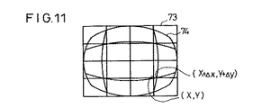
例えば、光軸に垂直な平面状の物体としての被写体を、図9例に示すような長方形(正方形でもよい。)が格子状に配列された長方形格子73とした場合に、ビデオカメラ1で撮像された画像が図10に示す、たる形に中央が膨らんだ画像74になるものとする。
【0081】
そこで、図11に示すように2つの画像を合わせて考慮すれば、スキャン座標生成部61で生成された座標(X,Y)に対応して、補正座標テーブル62から読み出されたアドレス補正座標(Δx,Δy)を加算した補正後の座標(X+Δx,Y+Δy)に基づく読み出しアドレスデータで画像メモリ4R、4Lから読み出すようにすれば、画像を正確な位置座標で読み出すことができるということが理解される。
【0082】
アドレス補正座標(Δx,Δy)は電球を空間的に位置がわかっている点に置き、それが画像上の何処に写っているかを探し、歪みがない場合の位置とのずれをアドレス補正座標(Δx,Δy)としてテーブルに書き込む。この場合、すべての点について行うと処理時間がかかるため粗な点について補正データを求め、間の点については多項式により近似した値を利用する。
【0083】
この実施の形態において、補正量であるアドレス補正座標(Δx,Δy)は、符号付の4ビットを使用し、X座標、Y座標共に、値が−8〜7までの画素数の補正が可能となっており、レンズ11R、11L等の歪みの程度としては、垂直方向で約6%(7.5÷120×100)程度まで許容している。
【0084】
この場合、アドレス補正座標(Δx,Δy)は、計算により求めているのではなく、実測値から求めているので、レンズの規則的な歪みの補正にとどまらず、フロントガラス等に存在する歪みのような不規則な歪みをも合わせて補正することができるという利点が得られる。
【0085】
このように補正座標テーブル62を設けることの理由および利点を課題と比較してまとめて再度説明すると、左右の画像を対応させる場合において、図9および図10を参照して説明したように、レンズ11R、11Lには収差があるため、中心(レンズ11R、11Lの中心であると同時に画像IR、ILの中心)を通る縦および横のそれぞれの直線は直線として撮像されるが、中心を通らない直線は、たる形歪み的あるいは糸巻き歪み的な曲線として撮像される。このため、対応する領域31、32が左右のビデオカメラ1R、1Lでは上下方向に移動してしまい、エピポーラーラインEPを基準とした同じ高さで探したのでは対応が採れないことになる。
【0086】
そこで、中心から離れた領域について対応を採る場合には、この歪みを補正してから対応を採る必要がある。
【0087】
この実施の形態において、スキャン座標生成部61で歪みがないと仮定した場合の理想的な状態での対応をとるべき領域31、32の座標(X,Y)が生成される。そして、この個々の座標値(X,Y)に対して予めルックアップテーブルとしての補正座標テーブル62に記憶されている補正値である補正座標(Δx,Δy)を読み出し、これらを加算器69により合成して画像メモリアドレス生成部64に供給することで、正確な、いわゆる真の座標に対応するメモリアドレスが画像メモリアドレス生成部64で生成される。
【0088】
この補正後のメモリアドレスにより画像メモリ4R、4Lから画像データを読み出して相関演算部65に供給することにより、レンズ11R、11Lに歪みが多少存在しても相関演算部65で対応が採れることになる。
【0089】
次に、図12は、図6、図7を参照して説明した一致度Hを求めるための相関演算部65の詳細な構成を示している。
【0090】
この相関演算部65は、基本的には、第1〜第4の演算ブロック81、82、83、84を有する、いわゆるパイプライン方式的処理である並列処理方式を採用している。
【0091】
理解の容易化のために、まず、パイプライン方式的処理を考慮しないで、具体的には、FIFOメモリ65iが存在しないものとして、第1演算ブロック81のみで、図6、図7を参照して説明した一致度Hを求めるための動作について説明する。そして、上述のように、誤対応が最も少なくなるそれぞれの小領域(原領域31と検索領域32)の大きさとしては、横方向の画素数nがn=7〜9画素程度、縦方向の画素数mがm=12〜15画素程度であるが、ここでは、理解を容易にするために、n=4、m=5として説明する。
【0092】
図13は、このような前提のもとでの、エピポーラーラインEP上に乗る仮想的な右画像データIrdの例を示している。原領域31の対象となる全画素データ数は、m×640=5×640箇であるものとする。
【0093】
図14は、同様に、エピポーラーラインEP上に乗る仮想的な左画像データIldの例を示している。検索領域32の対象となる全画素データ数は、m×768=5×768箇であるものとする。
【0094】
図12において、画像メモリ4Rから端子85を通じて原領域31の右画像データIrdが減算器65aの被減算入力端子に供給され、画像メモリ4Lから端子86を通じて検索領域32の左画像データIldが減算器65aの減算入力端子に供給される。
【0095】
まず、一般的に説明すると、減算器65aでは、縦方向の左右の画素データの差を取り、その差の絶対値が絶対値演算器65bで取られる。加算器65cは、縦方向の左右の画素データの差の絶対値の和を取るとともに、ラッチ65dにラッチされている前列の縦方向の左右の画素データの差の絶対値の和を加算する。
【0096】
FIFOメモリ65eには、横方向の画素数nに対応するn段分、この実施の形態では、当該列の分を除いて左側(前側)に4(=n)列分の縦方向の左右の画素データの差の絶対値の和が保持される。すなわち、この実施の形態において、FIFOメモリ65eは、最初(入力側)のメモリ65e1〜最後(出力側)のメモリ65e4までの4段ある。
【0097】
具体的に説明すると、1回目の演算(1列1行目)で加算器65cの出力側には、1列1行目の左右の画素データの差の絶対値|A1−a1|が現れ、かつ、この値|A1−a1|がラッチ65dに保持される。
【0098】
2回目の演算(1列2行目)で1列2行目の左右の画素データの差の絶対値|A2−a2|とラッチ65dに保持されているデータ|A1−a1|との和、すなわち、|A2−a2|+|A1−a1|が加算器65cの出力側に現れる。
したがって、5回目の演算後には、次の(13)式に示す1列目の左右の画素データの差の絶対値の和(データ)Σ▲1▼(以下、2列目以降を順次、Σ▲2▼、Σ▲3▼、Σ▲4▼、…Σ641とする。)が加算器65cの出力側に現れ、この和Σ▲1▼は、ラッチ65dに保持される。また、このデータΣ▲1▼は、FIFOメモリ65eの最初のメモリ65e1に格納される。
【0099】
Σ▲1▼=|A1−a1|+|A2−a2|+|A3−a3|+|A4−a4|+|A5−a5| …(13)
この1列目の左右の画素データの差の絶対値の和Σ▲1▼が、最初のメモリ65e1に格納された後、ラッチ65dは、端子89から供給される制御信号によりリセットされる。
【0100】
このようにして、ずらし量dxの値がdx=0での小領域31、32間での全ての1回目の計算が終了する4列(4=n)5行(5=m)目の演算終了後のラッチ65dに格納されるデータ値とFIFOメモリ65eに格納されるデータ値とラッチ65hに格納されるデータ値等を図15に模式的に示す。
【0101】
図15において、ずらし量dxの値がdx=0の場合における次の(14)式に示す最初に求められる一致度H0が加算器65gの出力側に現れている点に留意する。
【0102】
H0=Σ▲1▼+Σ▲2▼+Σ▲3▼+Σ▲4▼ …(14)
次に、5列5行目の演算終了後の図15に対応する図を図16に示す。図16から分かるように、ずらし量dxの値がdx=0の場合の検索領域32に対する一致度H0が出力端子90に現れる。
【0103】
この場合、加算器65fの出力側には、5列目のデータΣ▲5▼と1列目のデータΣ▲1▼との差Σ▲5▼−Σ▲1▼が現れるので、加算器65gの出力側には、ずらし量dxの値がdx=1の場合の検索領域32に対する次の(15)式に示す一致度H1が現れることになる。
【0104】
H1=Σ▲2▼+Σ▲3▼+Σ▲4▼+Σ▲5▼ …(15)
ここで、実際の15×15の小領域を水平方向にX=0〜639まで移動し、ずらし量dxをdx=128までの各一致度Hを求める際に、この実施の形態では、原領域31の左画像IL上で1画素分右にずらした位置での対応度Hを求めるとき、左端の縦方向の和(上例ではΣ▲1▼)を減じて右に加わる新たな列の縦方向の和(上例ではΣ▲5▼)を加えるようにしているので、演算回数を15×640×128=1,228,800回にすることができる。すなわち、小領域の横方向の幅(画素数)は計算時間に無関係になる。
【0105】
もし、上例のように演算しなくて、15×15の小領域を移動させこの小領域毎に各領域を構成する画素データの差を取って、一致度Hを、水平方向XをXがX=0〜639まで、ずらし量dxを128まで計算することにすると、演算回数は15×15×640×128=18,432,000回となり、最も演算時間のかかる絶対値演算器65bの1回の演算時間を100nsで実行した場合でも、総演算時間が1843msかかることになる。これに対して上例では、総演算時間が123msであり、約1/15に低減することができる。
【0106】
しかし、この総演算時間123msは、NTSC方式のフレームレートである33msより大きいので、フレームレート毎に、言い換えれば、1画面毎に一致度Hを計算する場合には、総演算時間123msを約1/4以下の時間にする必要がある。
【0107】
そこで、この実施の形態では、図12に示したように、第1演算ブロック81と同一構成の第2〜第4演算ブロック82、83、84を設け、縦方向の画素数mと同数のFIFOメモリ65iを直列に接続している。
この場合、簡単のために、図13、図14と同じ画像データを利用してパイプライン方式的処理動作を説明すれば、最初に、第1と第2の演算ブロック81、82を構成するFIFOメモリ65eを通じて、第3演算ブロック83を構成するFIFOメモリ65iに1列目の画素データa1〜a5までを転送する。したがって、この転送時点で、第2演算ブロック82を構成するFIFOメモリ65iには2列目の画素データb1〜b5が転送され、第1演算ブロック81を構成するFIFOメモリ65iには3列目の画素データc1〜c5が転送される。
【0108】
次に、次の4列目の画素データd1〜d5を第1演算ブロック81のFIFOメモリ65iに順次転送したとき、第4演算ブロック84では右1列目の画素データA1〜A5と左1列目の画素データa1〜a5に関連する上述の演算が行われ、第3演算ブロック83では右1列目の画素データA1〜A5と左2列目の画素データb1〜b5に関連する上述の演算が行われ、第2演算ブロック82では右1列目の画素データA1〜A5と左3列目の画素データc1〜c5に関連する上述の演算が行われ、第1演算ブロック81では右1列目の画素データA1〜A5と左4列目の画素データd1〜d5に関連する上述の演算が行われる。
【0109】
次いで、右2列目の画素データB1〜B5の転送に同期して次の左5列目の画素データe1〜e5を第1演算ブロック81のFIFOメモリ65iに順次転送したとき、第4演算ブロック84では右2列目の画素データB1〜B5と左2列目の画素データb1〜b5に関連する演算が行われ、第3演算ブロック83では右2列目の画素データB1〜B5と左3列目の画素データc1〜c5に関連する演算が行われ、第2演算ブロック82では右2列目の画素データB1〜B5と左4列目の画素データd1〜d5に関連する演算が行われ、第1演算ブロック81では右2列目の画素データB1〜B5と左5列目の画素データe1〜e5に関連する上述の演算が行われる。
【0110】
このようにして、次に、右3列目の画素データC1〜C5の転送に同期して次の左6列目の画素データf1〜f5を順次同期して転送するようにすれば、第4演算ブロック84では、ずらし量dxがdx=0、dx=4、……についての一致度Hを計算でき、同様に、第3演算ブロック83では、ずらし量dxがdx=1、dx=5、……についての一致度Hを計算でき、第2演算ブロック82では、ずらし量dxがdx=2、dx=6、……についての一致度Hを計算でき、第1演算ブロック81では、ずらし量dxがdx=3、dx=7、……についての一致度Hを同時に計算することできる。
【0111】
このように、パイプライン方式的処理の4並列にすれば、演算時間を約1/4に低減することができる。なお、上述の説明から理解できるように、第4演算ブロック84中のFIFOメモリ65iは不要である。
【0112】
この場合、図12例の4並列による動作によれば、1フレームレートで1フレームの画像についての640点の距離情報が求まり、左画像ILの横768画素×縦15画素の帯領域の処理が完了するが、これは1画像領域が768×240画素であることを考えると、全画像領域の1/16になる。
【0113】
なお、左右のカメラ1R、1Lの上下方向の取付位置がずれた場合等を想定した場合には、当初のエピポーラーラインEP上に対応する対象物画像が存在しなくなる場合も考えられる。この場合、図示はしないが、例えば、図9の対応処理装置6の構成を4並列にし、画像の縦方向の処理を4並列にすることにより、横768画素、縦15画素の帯領域4つをフレームレート内で処理することが可能となる。この場合に、領域が重ならないようにすることで、最大127画素のずれまで検出できる距離情報を1フレームレート内で(640−n)×4点出力できる。
【0114】
図12例の相関演算部65の処理により、1本のエピポーラーラインEP上における右画像IR中の640個の原領域31のそれぞれに対して、ずらし量dxがdx=0〜127の検索領域32についての128個の一致度Hが演算され、この演算結果の一致度Hが、相関メモリ67に格納される。
【0115】
また、1個の原領域31、すなわち、各変移位置Xに対する128個の検索領域32のうち、一致度Hが最小値となる値(ピーク値ともいう。)をピーク値検出部66で検出し、検出したピーク値(最小値)Hminを、そのときの変移位置Xとずらし量dxに対応させてピーク値メモリ68に記憶する。ピーク値メモリ68は、一致度Hのピーク値(最小値)記憶テーブルとして機能する。
【0116】
変移位置Xとずらし量dxをアドレスとして一致度Hが記憶されている相関メモリ67と、その最小値としてのピーク値Hminが記憶されているピーク値メモリ68が位置演算装置7に接続されている。
【0117】
位置演算装置7は、一致度Hとそのピーク値Hminとを参照し、図17に示すフローチャートに基づいて、対象物体Sの3次元空間での位置Pを求める。
【0118】
変移位置Xが所定の変移位置であるX=Xpの原領域31についての位置Pの算出方法について説明する。
【0119】
まず、所定の変移位置Xpの原領域31についての一致度Hのピーク値Hminと、そのときのずらし量dx(このずらし量dxをずらし量dxminと呼ぶ)をピーク値メモリ68から取り込む(ステップS21)。
【0120】
次に、このずらし量dxminの近傍の左右各2個の一致度H、すなわち、ずらし量dxがずらし量dxminより3つ少ないずれ量dxmin−2および3つ多いずれ量dxmin+2の各位置における一致度Hmin−2、Hmin+2を取り込む(ステップS22)。
【0121】
次に、次の(16)式に基づいて谷の深さ(ピーク深さともいう。)Qを求める(ステップS23)。
【0122】
Q=min{Hmin−2/Hmin,Hmin+2/Hmin} …(16)
この(16)式は、ピーク値Hminに対する、これから2つ隣の一致度Hmin−2、Hmin+2の大きさの各比のうち、最小値を取ることを意味する。
【0123】
そして、この谷の深さQが所定の閾値TH以上の値であるかどうか(Q≧TH)を判定し(ステップS24)、所定の閾値TH以上の値である場合には、ピーク値Hminであり、ずらし量dxminの検索領域32が所定の変移位置Xpの原領域31に対応する領域であると同定して次のステップS25に進む。
【0124】
一方、ステップS24の結果が否定的である場合には、ピーク値Hminであり、ずらし量dxminの検索領域32が所定の変移位置Xpの原領域31に対応する領域ではないと判断して、次の変移位置Xp+1の原領域31に対する対応する検索領域32を求める処理が全て終了したかどうかを判定し(ステップS28)、全ての変移位置Xに対応する処理が終了していない場合には、そのステップS21〜S24の処理を繰り返す。
【0125】
この実施の形態において、一致度Hのピーク値Hminを変移位置Xpの原領域31に対応する検索領域32であると直ちに同定しないで、その近傍を見て(ステップS22)、その谷の深さQを計算し(ステップS23)、その谷の深さQが所定の閾値TH以上の場合にのみ、一致度Hのピーク値Hminが得られるずらし量dxminの検索領域32が、変移位置Xpの原領域31に対応する検索領域32であると同定する理由は、雑音の混入または画像IR、ILの被写体の画像濃度が一様である場合等に、一致度Hのピーク値Hminが得られ、ずらし量dxminの検索領域32が、変移位置Xpの原領域31に必ずしも対応するとは限らないからである。
【0126】
すなわち、ずらし量dxminの位置の近傍領域を考慮して、谷の深さQが、所定の閾値THより小さいものは、対応がよく取れていないと判断し、その一致度Hのピーク値Hminは利用しないこととした。なお、所定の閾値THは、この実施の形態においては、TH=1.2とした。
【0127】
ステップS24の判断が肯定的であるとき、ずらし量dxの真の値(真のピーク位置という)dsを次に示す補間処理により求める(ステップS25)。すなわち、図18に示すように、最小位置座標を(dxmin,Hmin)とし、その前後の位置座標をそれぞれ(dxmin−1,Hmin−1)、(dxmin+1,Hmin+1)とするとき、前後の一致度Hmin−1、Hmin+1の大きさを比較して、それぞれ次の(17)式〜(19)式で示す値に推定する。
【0128】
Hmin−1<Hmin+1の場合、
ds=dxmin−{(Hmin−1−Hmin+1)/(2・(Hmin−Hmin+1))}…(17)
Hmin−1=Hmin+1の場合、
ds=dxmin …(18)
Hmin−1>Hmin+1の場合、
ds=dxmin+{(Hmin+1−Hmin−1)/(2・(Hmin−Hmin−1))}…(19)
この(17)式〜(19)式の補間式を用いて真のピーク位置dsを求めた場合には、補間しない場合に比較して、位置精度が3倍向上することを実験的に確認することができた。
【0129】
結局、ステップS25の補間処理終了後に、変移位置Xpの原領域31に最も対応する検索領域32の真のピーク位置dsが求まることになる。
【0130】
このようにして求められた変移位置Xpと真のピーク位置dsは、それぞれ、図5に示す右画像IR上の対象物体画像SRの視差dRと左画像IL上の対象物体画像SLの視差dLに対応する。
【0131】
しかし、実際上、上述したように、フロントガラスやカメラ1R、1Lの対物レンズ11R、11Lの光学特性によって、左右の画像IR、ILには、例えば、ピンクッション的歪み、あるいはバレル的歪みが存在するので、これらによる歪み補正を行った視差dRと視差dLとを求める(ステップS26)。
【0132】
そこで、これら歪み補正を行った視差dRと視差dLを測定値として、上述の(4)式〜(6)式から対象物体Sまでの奥行き方向の距離Zdと、その距離Zdからの左右の偏差にかかるずれ距離DRとずれ距離DLとの3次元位置情報を求めることができる(ステップS27)。
【0133】
ステップS28では、エピポーラーラインEP上の全ての変移位置Xでの原領域31に対応する検索領域32中の真のピーク位置dsを求める演算が終了したかどうか、すなわち、変移位置XがX=767であるかどうかを確認して処理を終了する。
【0134】
位置演算装置7で作成された、これら3次元位置情報である距離Zdとずれ距離DRとずれ距離DLとはクラスタリングされ、対象物体Sについての識別符号としての、いわゆるアイディ(ID:Identification)が付けられて、出力端子90を通じて、次の処理過程である、図示しない道路・障害物認識装置等に接続される。
【0135】
道路・障害物認識装置等は、自動運転システムを構成し、運転者に対する警告、車体の自動衝突回避、前走車への自動追従走行などの動作を行うことができる装置である。この場合、例えば、自動追従走行を行うシステムとして、本出願人の出願による「物体検出装置およびその方法」(特願平7−249747号)を挙げることができる。
【0136】
なお、この発明は上述の実施の形態に限らず、この発明の要旨を逸脱することなく種々の構成を採り得ることはもちろんである。
【0137】
【発明の効果】
以上説明したように、この発明によれば、2つのカメラは、車両の正面方向にある無限遠点が前記2つの撮像手段からそれぞれ得られる各画面中の中心となるように設置されており、対応処理手段が、2つの撮像手段から得られる各画像中の同一物体画像の対応を採る際に、歪み補正手段により光学部の歪みを原因とする撮像の歪みを補正した後に対応を採るようにしているので、レンズの歪み等、光学系の歪みに基づく画像の歪みを原因とする同一物体の対応の採れない状態を回避することができるという効果が達成される。
【図面の簡単な説明】
【図1】この発明の一実施の形態の構成を示すブロック図である。
【図2】ステレオカメラの据えつけ位置の説明に供される概略斜視図である。
【図3】三角測量の原理で距離を求める際の説明に供される平面視的図である。
【図4】対象物体にかかる左右画像上での視差の説明に供される線図であって、Aは、左側画像、Bは、右側画像をそれぞれ表す図である。
【図5】図1例の装置の全体的な動作説明に供されるフローチャートである。
【図6】左右の小領域の対応処理の仕方の説明に供される図である。
【図7】図6例の説明に供されるフローチャートである。
【図8】対応処理装置の詳細な構成を含む装置の構成を示すブロック図である。
【図9】被写体としての長方形格子を示す図である。
【図10】レンズの収差による歪みを含んで撮像された画像を示す図である。
【図11】図9の図形と図10の図形とを重ね合わせた補正座標の説明に供される図である。
【図12】相関演算部の詳細な構成を示す回路ブロック図である。
【図13】エピポーラーライン上の左画像データの一部を模式的に表す線図である。
【図14】エピポーラーライン上の右画像データの一部を模式的に表す線図である。
【図15】図12例中、第1演算ブロックの動作説明に供されるブロック図である。
【図16】図12例中、第1演算ブロックの動作説明に供される他のブロック図である。
【図17】位置演算装置の動作説明に供されるフローチャートである。
【図18】補間演算の説明に供される線図である。
【符号の説明】
1…ステレオカメラ 1R、1L…ビデオカメラ
2R、2L…CCU 4R、4L…画像メモリ
5R、5L…駆動回路 6…対応処理装置
7…位置演算装置 8…露光量調整装置
11R、11L…対物レンズ 13R、13L…CCDイメージセンサ
15R、15L…光軸 62…補正座標テーブル
73…長方形格子 74…たる形に中央が膨らんだ画像[0001]
TECHNICAL FIELD OF THE INVENTION
BACKGROUND OF THE
[0002]
[Prior art]
2. Description of the Related Art Conventionally, when trying to recognize the surrounding environment, a target object (simply called an object) based on the principle of triangulation from two images (also called a stereo image) obtained by a stereo camera using stereo vision. A so-called stereo method is adopted in which the distance to the object is determined and the position of the object is recognized.
[0003]
In this stereo method, it is a prerequisite that, when obtaining the distance, a correspondence of the same object can be obtained on two images captured through a lens.
[0004]
As a technique for taking the correspondence of the same object on two captured images, there is a method of focusing on a region in the images.
[0005]
In this method, first, a window having an appropriate size is set on one image, and an area having the same size as the window is set on the other image in order to obtain an area corresponding to the window in the other image.
[0006]
Next, the pixel data value of each corresponding pixel (specifically, each pixel corresponding to a matrix position) constituting an image in each window (also simply referred to as a window image) on both images is subtracted. Obtain the difference and also the absolute value of the difference.
[0007]
Then, the sum of the absolute value of the difference of each pixel in the window, that is, the so-called sum is calculated.
[0008]
In this way, the calculation for obtaining the sum of the absolute values of the differences between the pixel data values in the window is sequentially performed while changing the position of the window on the other image, and the window of the other image in which the sum is minimized is determined as the one-window. This is a method of determining that the region is an area corresponding to the window of the image.
[0009]
The present invention also basically employs a method that focuses on the region in the image.
[0010]
[Problems to be solved by the invention]
By the way, when an image is captured by a stereo camera mounted on a vehicle, for example, two video cameras spaced apart from each other at a fixed distance on a base line, light having image information is transmitted through a windshield and a lens constituting the video camera. Is introduced into an image pickup device such as a CCD area sensor through an optical system including the above, and is subjected to photoelectric conversion by this image pickup device and output as an electric signal, that is, a video signal. This video signal is divided corresponding to pixels, converted into image data which is a digital signal, and stored in an image memory such as a frame memory.
[0011]
However, there is distortion in a windshield, a lens, and the like. In a lens having particularly large distortion, aberrations such as so-called pincushion (pincushion) distortion and barrel (barrel) distortion exist. This is not considered in the technology.
[0012]
Therefore, normally, when a horizontal line passing through the center of the lens is considered, this imaging is a straight line, and the correspondence of the images can be obtained by the above-described correspondence processing. However, the image of the peripheral portion of the lens has a curved curved horizontal line. In addition, there was a problem that it was not possible to take a correspondence by assuming a straight line.
[0013]
As a technique related to this application, for example, a technique disclosed in Japanese Patent Application Laid-Open No. HEI 6-282793 can be cited. However, in this publication, the brightness is simply reduced around the lens due to vignetting. It only describes the content of preparing in advance a correction value for correcting, but does not disclose any technique for motivating lens distortion.
[0014]
The present invention has been made in view of such a problem, and makes it possible to avoid an incompatible state of the same object due to distortion of an image due to distortion of an optical system such as distortion of a lens. An object of the present invention is to provide a vehicle environment recognition device.
[0015]
[Means for Solving the Problems]
The present invention, for example, as shown in FIGS.
Capturing light with
eachPictureIn the statueCorrespondence processing means 6 for taking correspondence of the same object image of
Position calculation means 7 for calculating the distance to the corresponding object taken based on the principle of triangulation;
The corresponding processing unit acquires using the correction data prepared in advance using the
The corresponding processing meansLeft and right acquisition with distortion correctionscreenAre moved along the epipolar line EP, and the correspondence between the same object images is determined by detecting the degree of coincidence of the images in both windows.In doing so, the window is moved a predetermined distance in one screen, and the coincidence detection is performed by moving the window in the other screen within a predetermined range based on the position of the window in the one screen,
The predetermined range is a range determined according to the horizontal angle of view of the imaging unit, the number of pixels in the horizontal direction, the shortest detection distance of the object, and the base line length of the two imaging units.It is characterized by the following.
[0016]
According to the present invention, the correspondence processing means:TwoObtained from the imaging meanseachIn the image signalSameWhen taking the correspondence of the object image, the distortion correction unit corrects the imaging distortion caused by the distortion of the optical unit and then takes the correspondence, so that the image based on the distortion of the optical system such as the lens distortion. It is possible to avoid a state in which the same object cannot be handled due to the distortion.
[0017]
According to the invention,The distortion correction unit has an address correction table for correcting a pixel read address from the image memory as the correction data,When reading the image data stored in the image memory in pixel units and taking the correspondence of the same object image,In one of the left and right images, the window is moved by a predetermined distance (for example, 640 pixels) along the epipolar line, and in the other image, the window is moved by the horizontal angle of view (θ) of the imaging unit and the number of pixels in the horizontal direction. (N), moving the object within a predetermined range determined according to the shortest detection distance (Zd) of the object and the base line length (D) of the two imaging means, and taking correspondence of the same object image.With such a configuration, it is possible to avoid an incompatible state due to an image distortion due to an optical system distortion such as a lens distortion with a simple configuration.
[0018]
In this case, the address correction table stores the address correction data as signed bit data corresponding to the address before correction.When the degree of coincidence is detected, an operation is performed using at least one of a pipeline process and a parallel process.. With this configuration, it is possible to have a configuration in which a corresponding address correction table is provided for each optical unit, and as a result, an address correction table corresponding to the optical unit distortion characteristic of the imaging unit is attached to the imaging unit. Can be.Further, the calculation time can be reduced.
[0019]
BEST MODE FOR CARRYING OUT THE INVENTION
Hereinafter, an embodiment of the present invention will be described with reference to the drawings.
[0020]
FIG. 1 is a block diagram showing a configuration of an embodiment of the present invention.
[0021]
In FIG. 1, a
[0022]
Further, the
[0023]
As can be seen from FIG. 1, the right and left
[0024]
The
[0025]
The output signals of the left and
[0026]
The AD converters 3R and 3L convert an analog video signal into a digital signal, and form an image signal (hereinafter referred to as a necessity) as a set of pixels having 768 columns in the horizontal direction and 240 rows in the vertical direction. Accordingly, the image data is also referred to as image data as a set of pixel data, and is actually not video signal based on density but video signal data based on luminance. It is stored in the
[0027]
In this embodiment, the image memory (also referred to as a pixel memory when a pixel constituting an image is considered) has a value equal to the number of pixels in the horizontal direction × the number of pixels in the vertical direction. It is assumed that one pixel memory is provided. Each of the
[0028]
Since the images stored in the
[0029]
A predetermined operation is performed by sequentially comparing the image data of the same size area of the
[0030]
The position processing device 7 which calculates the relative position of the target based on the triangulation method (binocular stereovision) according to the corresponding region (corresponding address position) of the target in the left and
[0031]
Prior to the correspondence processing / position calculation in the correspondence processing device 6 and the position calculation device 7, the input side has image information incident on the
[0032]
The exposure adjusting device 8 determines an exposure based on image data of a predetermined area of the
[0033]
Of the
[0034]
Next, the operation of the above embodiment and a more detailed configuration as necessary will be described.
[0035]
FIG. 3 is a plan view showing a state in which the scene including the target object S is imaged by the left and
[0036]
4A shows an image (also referred to as a right image or a right image) IR including the target object S captured by the
[0037]
The parallaxes dR and dL shown in FIG. 3 on the
[0038]
From FIG. 3, it can be seen that the following equations (1) to (3) hold.
[0039]
DR: Zd = dR: F (1)
DL: Zd = dL: F (2)
D = DR + DL (3)
From these equations (1) to (3), the distance Zd, the shift distance DR, and the shift distance DL can be obtained by the equations (4) to (6), respectively.
[0040]
Zd = F × D / (DR + DL) (4)
DR = dR × D / (dL + dR) (5)
DL = dL × D / (dL + dR) (6)
By clustering the distance Zd, the shift distance DR, and the shift distance DL, which are these pieces of position information, and applying a so-called ID (Identification) as an identification code for the target object S, application to a vehicle tracking device or the like is performed. Can be achieved.
[0041]
As a practical problem, since it is difficult to measure the physical size of one effective pixel of the
[0042]
That is, for example, the horizontal angle of view of the
[0043]
Zd = N × D / {2 (NL + NR) tan (θ / 2)} (7)
DR = NR · D / (NL + NR) (8)
DL = NL · D / (NL + NR) (9)
Here, the horizontal angle of view θ is a measurable value, and the number N of effective pixels in the horizontal direction (N = 768 as described above in this embodiment) is predetermined and corresponds to the parallaxes dR and dL. The number of pixels NR and NL are also values that can be understood from the captured image.
[0044]
Next, the entire process from the above-described image capture to ID assignment will be described with reference to a flowchart, as shown in FIG.
[0045]
That is, the video signal data output from the AD converters 3R and 3L are captured and stored in the
[0046]
Subsequent to step S1, an image corresponding to an image of a certain area stored in the
[0047]
After taking the correspondence, the parallaxes dR and dL in the
[0048]
The position information is clustered (step S4), and an ID is assigned (step S5).
[0049]
Although the output with the ID, which is the output of the position calculation device 7, is not a main part of the present invention, it will not be described in detail. An operation system can be configured. In this automatic driving system, it is possible to perform operations such as a warning to the driver, a collision avoidance of the automobile (own vehicle equipped with the stereo camera 1) M, and an automatic following of the preceding vehicle.
[0050]
In this embodiment, in step S2 for associating the left and right images described above, not the method focusing on so-called features, but basically adopting the method focusing on the region in the image described in the section of the related art. are doing.
[0051]
In other words, a method of extracting some feature such as an edge, a line segment, or a special shape, and focusing on the feature that a portion where the feature coincides with a corresponding portion is adopted because the amount of information to be handled decreases. First, in this embodiment, a small area surrounding the target object image SR, a so-called window, is cut out from one image, the right image IR, and a small area similar to this small area is searched from the other left image IL to determine the correspondence. Adopt a method to determine.
[0052]
In the method adopted in this embodiment, which focuses on a region in an image, a window of an appropriate size is set on one of the images IL and IR as a technique for taking correspondence of the same target object S on one of the images. In order to obtain an area corresponding to this window in the other image, an area having the same size as the window is set in the other image.
[0053]
Next, the pixel data value of each corresponding pixel (specifically, each pixel corresponding to the matrix position in the window image) constituting the image in each window (also simply referred to as a window image) on both images is described. That is, the difference is obtained by subtracting the luminance value, and further, the absolute value of the luminance difference is obtained.
[0054]
Then, a sum in the window of the absolute value of the luminance difference for each corresponding pixel, that is, a so-called sum is obtained.
[0055]
This sum is defined as the degree of coincidence (also called degree of correspondence) H between the left and right images. At this time, the brightness (pixel data value) of the corresponding coordinate point (x, y) in the window of the right image IR and the left image IL is set to IR (x, y) and IL (x, y), respectively, and the width of the window is set. If n pixels (n is the number of pixels) and the vertical width is m pixels (m is also the number of pixels), and if the shift amount is dx (described later), the degree of coincidence H is obtained by the following equation (10). Can be.
[0056]
H (x, y) = {(j = 1 → m)} (i = 1 → n) | Id | (10)
here,
| Id | = | IR (x + i, y + j) −IL (x + i + dx, y + j) |
It is. The symbol Σ (i = 1 → n) represents the sum of | Id | from i = 1 to i = n, and the symbol Σ (j = 1 → m) is Σ (i = 1 → n) | Id | Represents the sum of the results of | from j = 1 to j = m.
[0057]
From equation (10), it can be seen that the smaller the degree of coincidence H, in other words, the smaller the sum of the absolute values of the luminance differences, the better the left and right window images match.
[0058]
In this case, if the size of the window to be divided, that is, the size of the small area is too large, there is a high possibility that other objects having different relative distances Zd are present in the area at the same time, and the erroneous correspondence may occur. Will be higher. On the other hand, if the size of the small region is too small, there is a problem that erroneous responses corresponding to erroneous positions or erroneous responses due to noise increase. The present inventors have found from various experimental results that the size of the small area where the number of erroneous correspondences is the least is about n = 7 to 9 in the horizontal direction and m = 12 to 9 in the vertical direction. I found it to be about 15 in size.
[0059]
6 and 7 show the concept of how to move the area when performing the correspondence calculation for obtaining the degree of coincidence H in the correspondence processing device 6. FIG.
[0060]
As shown in FIG. 6, a predetermined area (also referred to as a small area or an original area) 31 on the right image IR from which a correspondence is to be obtained is shifted 640 pixels by one pixel from the left end position in the X-axis direction to the right. A predetermined area (also referred to as a small area or a search area) 32 of the left image IL to be associated with is located at a position corresponding to the left end position of the
[0061]
Note that the reason for limiting to 128 pixels is that the horizontal view angle θ is 40 °, the shortest distance Zd is Zd = 5 m, and the usable stereo camera 1 (
[0062]
NL + NR = (N × D) / {Zd × 2 × tan (θ / 2)}
= (768 × 0.5) / (5 × 2 × tan20 °) (11) This means that the target imaged at the position of X = 0 (left end) in the right image IR is always the left image IL Means that the image is captured in the 127th pixel position from the 0th pixel position corresponding to the shift amount dx of dx = 0 to 127. Therefore, the X-coordinate value (also referred to as a displacement position) of the imaging target in the
[0063]
At this time, since the rightmost pixel of the
[0064]
Therefore, as shown in the flowchart of FIG. 7, first, the
[0065]
Next, it is determined whether or not the shift amount dx exceeds dx = 127, that is, whether or not dx = 128 (step S13).
[0066]
If this determination is negative, pixel data for 32 search regions (small regions) of the left image IL is extracted to calculate the degree of correspondence H (step S14).
[0067]
Next, the sum of the absolute values of the differences between the pixels of the
[0068]
Next, the shift amount dx is increased by one pixel as dx → dx + 1 (in this case, dx = 1) (step S16).
[0069]
At this time, since the determination in step S13 is not established, next, the
[0070]
Similarly, the degree of coincidence H is calculated for the
[0071]
When the determination in step S13 is affirmative, that is, the minimum value Hmin, which is a negative peak value, and values in the vicinity of the minimum value Hmin are obtained from the coincidence H calculated for the
[0072]
Next, although not described in the flowchart of FIG. 7 because of complexity, steps S11 to S17 described above are repeated until the displacement position X in the right image IR is X = 1 to 767 (or 640-n). The
[0073]
FIG. 8 is a block diagram showing a detailed configuration of the correspondence processing device 6 that calculates the degree of coincidence H based on the operation explanatory diagram of FIG. 6 and the flowchart of FIG.
[0074]
Figure8In the middle and scan coordinate
[0075]
Based on the coordinates (X, Y) generated by the scan coordinate
[0076]
Therefore, the corrected coordinates (X + Δx, Y + Δy) added by the
[0077]
The calculation of the degree of coincidence H based on the image data read from the
[0078]
The address correction coordinates (Δx, Δy) stored in the correction coordinate table 62 correspond to each optical system for the
[0079]
The address correction coordinates (Δx, Δy) are aberrations in which a planar object perpendicular to the optical axis is not imaged in a similar manner on the imaging surface perpendicular to the optical axis, here, the imaging surfaces of the
[0080]
For example, when the object as a planar object perpendicular to the optical axis is a
[0081]
Therefore, if the two images are considered together as shown in FIG. 11, the address correction coordinates read from the correction coordinate table 62 corresponding to the coordinates (X, Y) generated by the scan coordinate
[0082]
The address correction coordinates (Δx, Δy) are obtained by placing the light bulb at a point whose position is spatially known, searching where the light bulb is located on the image, and determining the deviation from the position where there is no distortion by the address correction coordinates ( Δx, Δy) in the table. In this case, it takes processing time to perform processing for all points, so that correction data is obtained for coarse points, and values approximated by a polynomial are used for points in between.
[0083]
In this embodiment, the address correction coordinates (Δx, Δy), which are correction amounts, use signed 4 bits, and can correct the number of pixels having a value of −8 to 7 for both the X coordinate and the Y coordinate. The degree of distortion of the
[0084]
In this case, the address correction coordinates (Δx, Δy) are not obtained by calculation, but are obtained from actual measurement values. There is an advantage that such irregular distortion can be corrected together.
[0085]
The reason and the advantage of providing the correction coordinate table 62 in this way will be described again in comparison with the problem. When the left and right images are associated with each other, as described with reference to FIG. 9 and FIG. Since 11R and 11L have aberrations, the vertical and horizontal straight lines passing through the center (the center of the images IR and IL at the same time as the centers of the
[0086]
Therefore, when taking a measure for a region distant from the center, it is necessary to correct the distortion before taking a measure.
[0087]
In this embodiment, the coordinates (X, Y) of the
[0088]
By reading out the image data from the
[0089]
Next, FIG. 12 shows a detailed configuration of the
[0090]
The
[0091]
For ease of understanding, first, without considering the pipeline-type processing, specifically, assuming that the FIFO memory 65i does not exist, only the first operation block 81 will be described with reference to FIGS. The operation for obtaining the degree of coincidence H described above will be described. As described above, the size of each of the small areas (the
[0092]
FIG. 13 shows an example of virtual right image data Ird on the epipolar line EP under such a premise. It is assumed that the total number of pixel data to be processed in the
[0093]
FIG. 14 similarly shows an example of virtual left image data Ild riding on the epipolar line EP. It is assumed that the total number of pixel data targeted for the
[0094]
In FIG. 12, the right image data Ird of the
[0095]
First, generally speaking, the
[0096]
The
[0097]
More specifically, the absolute value | A1-a1 | of the difference between the left and right pixel data in the first column and the first row appears on the output side of the
[0098]
The sum of the absolute value | A2-a2 | of the difference between the left and right pixel data in the first column and the second row in the second calculation (first column and second row) and the data | A1-a1 | That is, | A2-a2 | + | A1-a1 | appears on the output side of the
Therefore, after the fifth operation, the sum (data) of the absolute value of the difference between the left and right pixel data in the first column shown in the following equation (13) (1) (2), (3), (4),..., 641) appear on the output side of the
[0099]
{1} = | A1-a1 | + | A2-a2 | + | A3-a3 | + | A4-a4 | + | A5-a5 | (13)
After the sum of the absolute values of the difference between the left and right pixel data in the first column, {1}, is stored in the first memory 65e1, the
[0100]
In this manner, the calculation of the fourth column (4 = n) and the fifth row (5 = m) in which the first calculation is completed between the
[0101]
In FIG. 15, it should be noted that, when the value of the shift amount dx is dx = 0, the first degree of coincidence H0 shown in the following equation (14) appears on the output side of the
[0102]
H0 = Σ11 + Σ2 ▼ + Σ3 ▼ + Σ4 ▼ (14)
Next, FIG. 16 shows a diagram corresponding to FIG. 15 after the completion of the calculation in the fifth column and the fifth row. As can be seen from FIG. 16, the degree of
[0103]
In this case, a difference (5)-(1) between the data in the fifth column (5) and the data in the first column (1) appears on the output side of the
[0104]
H1 = Σ (2) + Σ (3) + Σ (4) + Σ (5)… (15)
Here, when the actual 15 × 15 small area is moved in the horizontal direction from X = 0 to 639 and the shift amount dx is obtained for each degree of coincidence H up to dx = 128, in this embodiment, the original area is used. When the degree of correspondence H at a position shifted by one pixel to the right on the left image IL of 31 is obtained, the vertical sum of the left end (in the above example, {circle around (1)}) is subtracted, and the height of the new column added to the right is reduced. Since the sum of the directions (Σ5 in the above example) is added, the number of operations can be made 15 × 640 × 128 = 1, 228,800. That is, the width (the number of pixels) of the small region in the horizontal direction is independent of the calculation time.
[0105]
If the calculation is not performed as in the above example, the small area of 15 × 15 is moved, and the difference between the pixel data constituting each area is calculated for each of the small areas. If X = 0 to 639 and the shift amount dx is calculated up to 128, the number of operations is 15 × 15 × 640 × 128 = 18,432,000, which is one of the absolute value operation units 65b which requires the longest operation time. Even if the calculation time is 100 ns, the total calculation time will be 1843 ms. On the other hand, in the above example, the total operation time is 123 ms, which can be reduced to about 1/15.
[0106]
However, since the total operation time 123 ms is greater than the NTSC frame rate of 33 ms, when calculating the coincidence H for each frame rate, in other words, for each screen, the total operation time 123 ms is reduced to about 1 ms. It is necessary to set the time to / 4 or less.
[0107]
Therefore, in this embodiment, as shown in FIG. 12, the second to fourth operation blocks 82, 83, and 84 having the same configuration as the first operation block 81 are provided, and the same number of FIFOs as the number m of pixels in the vertical direction are provided. The memories 65i are connected in series.
In this case, for the sake of simplicity, a description will be given of a pipeline processing operation using the same image data as in FIGS. 13 and 14. First, the FIFOs constituting the first and second arithmetic blocks 81 and 82 will be described first. The pixel data a1 to a5 in the first column are transferred to the FIFO memory 65i constituting the
[0108]
Next, when the pixel data d1 to d5 of the next fourth column are sequentially transferred to the FIFO memory 65i of the first arithmetic block 81, the pixel data A1 to A5 of the right first column and the left one column The above-described calculation relating to the pixel data a1 to a5 of the second eye is performed. In the
[0109]
Next, in synchronization with the transfer of the pixel data B1 to B5 in the second right column, when the next pixel data e1 to e5 in the fifth left column are sequentially transferred to the FIFO memory 65i of the first calculation block 81, the fourth calculation block In 84, operations related to the pixel data B1 to B5 in the second right column and the pixel data b1 to b5 in the second left column are performed. In the
[0110]
In this way, if the pixel data f1 to f5 in the next left sixth column are sequentially transferred in synchronization with the transfer of the pixel data C1 to C5 in the third right column, the fourth In the
[0111]
As described above, the calculation time can be reduced to about 1/4 by performing four parallel processes of the pipeline system. As can be understood from the above description, the FIFO memory 65i in the
[0112]
In this case, according to the four-parallel operation in the example of FIG. 12, distance information of 640 points for one frame image is obtained at one frame rate, and processing of a band area of 768 pixels × 15 pixels of the left image IL is performed. This is completed, but this is 1/16 of the entire image area, considering that one image area is 768 × 240 pixels.
[0113]
In addition, when it is assumed that the mounting positions of the left and
[0114]
By the processing of the
[0115]
The peak
[0116]
A
[0117]
The position calculation device 7 refers to the coincidence H and its peak value Hmin, and obtains the position P of the target object S in the three-dimensional space based on the flowchart shown in FIG.
[0118]
A method of calculating the position P for the
[0119]
First, the peak value Hmin of the degree of coincidence H of the
[0120]
Next, the degree of coincidence H of each of the two right and left in the vicinity of the shift amount dxmin, that is, the degree of coincidence at each position of the shift amount dxmin-2 and the shift amount dxmin + 2 three times less than the shift amount dxmin. Hmin-2 and Hmin + 2 are fetched (step S22).
[0121]
Next, a valley depth (also referred to as a peak depth) Q is obtained based on the following equation (16) (step S23).
[0122]
Q = min {Hmin-2 / Hmin, Hmin + 2 / Hmin} (16)
This equation (16) means that the minimum value is taken out of the ratios of the magnitudes of the coincidences Hmin−2 and Hmin + 2 two adjacent to the peak value Hmin.
[0123]
Then, it is determined whether or not the depth Q of the valley is equal to or greater than a predetermined threshold value TH (Q ≧ TH) (step S24). If the depth Q is equal to or greater than the predetermined threshold value TH, the peak value Hmin is set. Yes, the
[0124]
On the other hand, if the result of step S24 is negative, it is determined that the
[0125]
In this embodiment, the vicinity of the peak value Hmin of the coincidence H is not immediately identified as the
[0126]
That is, when the valley depth Q is smaller than the predetermined threshold TH in consideration of the vicinity area of the position of the shift amount dxmin, it is determined that the valley is not well-corresponding, and the peak value Hmin of the coincidence H is We decided not to use it. In this embodiment, the predetermined threshold TH is set to TH = 1.2.
[0127]
When the determination in step S24 is affirmative, a true value (referred to as a true peak position) ds of the shift amount dx is obtained by the following interpolation processing (step S25). That is, as shown in FIG. 18, when the minimum position coordinate is (dxmin, Hmin) and the position coordinates before and after that are (dxmin-1, Hmin-1) and (dxmin + 1, Hmin + 1), respectively, The magnitudes of Hmin-1 and Hmin + 1 are compared and estimated to values shown by the following equations (17) to (19), respectively.
[0128]
If Hmin-1 <
ds = dxmin − {(Hmin−1−Hmin + 1) / (2 · (Hmin−Hmin + 1))} (17)
If Hmin-1 =
ds = dxmin (18)
If Hmin-1> Hmin + 1,
ds = dxmin + {(Hmin + 1−Hmin−1) / (2 · (Hmin−Hmin−1))} (19)
When the true peak position ds is obtained by using the interpolation formulas (17) to (19), it is experimentally confirmed that the position accuracy is improved three times as compared with the case where no interpolation is performed. I was able to.
[0129]
After all, after the interpolation processing in step S25, the true peak position ds of the
[0130]
The shift position Xp and the true peak position ds obtained in this way are respectively the parallax dR of the target object image SR on the right image IR and the parallax dL of the target object image SL on the left image IL shown in FIG. Corresponding.
[0131]
However, in practice, as described above, the left and right images IR and IL have, for example, pincushion-like distortion or barrel-like distortion due to the windshield and the optical characteristics of the
[0132]
Therefore, using the disparity dR and the disparity dL subjected to the distortion correction as measurement values, the distance Zd in the depth direction to the target object S from the above equations (4) to (6) and the left-right deviation from the distance Zd , The three-dimensional position information of the shift distance DR and the shift distance DL can be obtained (step S27).
[0133]
In step S28, it is determined whether the calculation for finding the true peak position ds in the
[0134]
The distance Zd, the shift distance DR, and the shift distance DL, which are the three-dimensional position information created by the position calculation device 7, are clustered, and a so-called ID (Identification) is attached as an identification code for the target object S. Then, through an
[0135]
The road / obstacle recognition device and the like are devices that constitute an automatic driving system and can perform operations such as a warning to a driver, automatic collision avoidance of a vehicle body, and automatic following of a preceding vehicle. In this case, for example, as an example of a system that performs automatic following travel, an “object detection apparatus and method” (Japanese Patent Application No. 7-249747) filed by the present applicant can be cited.
[0136]
It should be noted that the present invention is not limited to the above-described embodiment, but may adopt various configurations without departing from the gist of the present invention.
[0137]
【The invention's effect】
As described above, according to the present invention,The two cameras are installed such that the point at infinity in the front direction of the vehicle is the center of each screen obtained from each of the two imaging units.Corresponding processing means is provided for each image obtained from the two imaging means.In the statueWhen the correspondence of the same object image is taken, the correspondence is taken after the distortion of the imaging caused by the distortion of the optical unit is corrected by the distortion correcting means, so that the correspondence is based on the distortion of the optical system such as the lens distortion. This achieves an effect that an incompatible state of the same object due to image distortion can be avoided.
[Brief description of the drawings]
FIG. 1 is a block diagram showing a configuration of an embodiment of the present invention.
FIG. 2 is a schematic perspective view for explaining an installation position of the stereo camera.
FIG. 3 is a plan view used for explanation when obtaining a distance based on the principle of triangulation.
FIG. 4 is a diagram for explaining parallax of a target object on left and right images, where A is a left image and B is a right image;
FIG. 5 is a flowchart for explaining the overall operation of the apparatus of FIG. 1;
FIG. 6 is a diagram which is used for describing a method of handling left and right small areas.
FIG. 7 is a flowchart provided for explaining the example in FIG. 6;
FIG. 8 is a block diagram illustrating a configuration of an apparatus including a detailed configuration of a corresponding processing apparatus.
FIG. 9 is a diagram showing a rectangular grid as a subject.
FIG. 10 is a diagram illustrating an image captured including distortion due to aberration of a lens.
FIG. 11 is a diagram provided for describing correction coordinates obtained by superimposing the graphic in FIG. 9 and the graphic in FIG. 10;
FIG. 12 is a circuit block diagram illustrating a detailed configuration of a correlation operation unit.
FIG. 13 is a diagram schematically illustrating a part of left image data on an epipolar line.
FIG. 14 is a diagram schematically illustrating a part of right image data on an epipolar line.
FIG. 15 is a block diagram for explaining the operation of a first operation block in the example of FIG. 12;
FIG. 16 is another block diagram used for describing the operation of the first operation block in the example of FIG. 12;
FIG. 17 is a flowchart used to describe the operation of the position calculation device.
FIG. 18 is a diagram provided for explanation of interpolation calculation.
[Explanation of symbols]
1:
2R, 2L ...
5R, 5L ... Drive circuit 6 ... Compatible processing device
7 Position calculating device 8 Exposure amount adjusting device
11R, 11L:
15R, 15L: Optical axis 62: Correction coordinate table
73 ...
Claims (2)
前記2つのカメラは、車両の正面方向にある無限遠点が2つの前記撮像手段からそれぞれ得られる各画面中の中心となるように設置され、
前記各画面中の同一物体画像の対応を採る対応処理手段と、
対応の採れた同一物体までの距離を三角測量の原理に基づき演算する位置演算手段とを備え、
前記対応処理手段は、前記光学部と前記撮像手段とを用いて予め準備された補正データを使用して取得画面の光学的な歪みを補正する歪み補正手段を有し、
前記対応処理手段が、歪みが補正された左右の取得画面内の同一形状を有するウィンドウをエピポーラーラインに沿って移動させて、両ウィンドウ内の画像の一致度を検出することで同一物体画像の対応を採る際に、一方の画面内でウィンドウを所定距離移動させるとともに、前記一方の画面内のウィンドウの位置を基準とする所定範囲内で他方の画面内のウィンドウを移動させて一致度検出を行い、
前記所定範囲は、前記撮像手段の水平画角、水平方向の画素数、物体の最短検出距離及び前記2つの撮像手段の基線長に応じて定められる範囲であることを特徴とする車両用環境認識装置。 Has two cameras consisting imaging means for capturing an image formed through the optical faculties light Faculty Ru captures light having image information,
The two cameras are installed such that an infinity point in the front direction of the vehicle is the center of each screen obtained from each of the two imaging units.
And corresponding processing means to take corresponding prior Symbol same object image in each screen,
Position calculation means for calculating the distance to the same taken corresponding object based on the principle of triangulation,
The correspondence processing unit has a distortion correction unit that corrects optical distortion of an acquisition screen using correction data prepared in advance using the optical unit and the imaging unit,
The correspondence processing unit moves windows having the same shape in the left and right acquisition screens in which the distortion has been corrected along the epipolar line, and detects the degree of coincidence of the images in both windows, thereby detecting the same object image. When taking the correspondence , the window is moved by a predetermined distance in one screen, and the window in the other screen is moved within a predetermined range based on the position of the window in the one screen to detect the degree of coincidence. Do
The environment recognition for a vehicle is characterized in that the predetermined range is a range determined according to a horizontal angle of view of the imaging unit, a number of pixels in a horizontal direction, a shortest detection distance of an object, and a base line length of the two imaging units. apparatus.
Priority Applications (1)
| Application Number | Priority Date | Filing Date | Title |
|---|---|---|---|
| JP31566795A JP3599255B2 (en) | 1995-12-04 | 1995-12-04 | Environment recognition device for vehicles |
Applications Claiming Priority (1)
| Application Number | Priority Date | Filing Date | Title |
|---|---|---|---|
| JP31566795A JP3599255B2 (en) | 1995-12-04 | 1995-12-04 | Environment recognition device for vehicles |
Publications (2)
| Publication Number | Publication Date |
|---|---|
| JPH09159442A JPH09159442A (en) | 1997-06-20 |
| JP3599255B2 true JP3599255B2 (en) | 2004-12-08 |
Family
ID=18068135
Family Applications (1)
| Application Number | Title | Priority Date | Filing Date |
|---|---|---|---|
| JP31566795A Expired - Fee Related JP3599255B2 (en) | 1995-12-04 | 1995-12-04 | Environment recognition device for vehicles |
Country Status (1)
| Country | Link |
|---|---|
| JP (1) | JP3599255B2 (en) |
Families Citing this family (11)
| Publication number | Priority date | Publication date | Assignee | Title |
|---|---|---|---|---|
| EP1368970B1 (en) * | 2001-03-05 | 2005-08-10 | Siemens Aktiengesellschaft | Method and device for correcting an image, particularly for occupant protection systems |
| US7327856B2 (en) * | 2001-05-25 | 2008-02-05 | Siemens Aktiengesellschaft | Arrangement and method for processing image data |
| JP2006052975A (en) * | 2004-08-10 | 2006-02-23 | Nikon Corp | Binocular vision device |
| US7782374B2 (en) | 2005-03-03 | 2010-08-24 | Nissan Motor Co., Ltd. | Processor and processing method for generating a panoramic image for a vehicle |
| JP4715334B2 (en) | 2005-06-24 | 2011-07-06 | 日産自動車株式会社 | Vehicular image generation apparatus and method |
| JP5011049B2 (en) * | 2007-09-28 | 2012-08-29 | 日立オートモティブシステムズ株式会社 | Image processing system |
| US7889234B2 (en) * | 2008-01-10 | 2011-02-15 | Delphi Technologies, Inc. | Automatic calibration for camera lens distortion correction |
| JP5365387B2 (en) * | 2009-07-17 | 2013-12-11 | 株式会社ニコン | Position detection device |
| JP5779512B2 (en) * | 2012-01-24 | 2015-09-16 | 株式会社ソシオネクスト | Image optical distortion correction apparatus, image optical distortion correction method, and image generation apparatus having image optical distortion correction apparatus |
| JP5634558B2 (en) * | 2013-04-30 | 2014-12-03 | 株式会社東芝 | Image processing device |
| JP6427900B2 (en) * | 2014-03-07 | 2018-11-28 | 株式会社リコー | Calibration method, calibration system, program, and moving object |
Family Cites Families (7)
| Publication number | Priority date | Publication date | Assignee | Title |
|---|---|---|---|---|
| JPS5853707A (en) * | 1981-09-25 | 1983-03-30 | Toshiba Corp | Correcting method for distortion in picture of television camera in tridimensional distance measuring device |
| JP2508916B2 (en) * | 1990-11-29 | 1996-06-19 | 三菱電機株式会社 | Tracking distance measuring device |
| JP3033204B2 (en) * | 1991-01-31 | 2000-04-17 | 松下電工株式会社 | TV intercom |
| JP2887039B2 (en) * | 1993-03-26 | 1999-04-26 | 三菱電機株式会社 | Vehicle periphery monitoring device |
| JP3367170B2 (en) * | 1993-11-05 | 2003-01-14 | 株式会社豊田中央研究所 | Obstacle detection device |
| JP2725613B2 (en) * | 1994-02-28 | 1998-03-11 | 日本電気株式会社 | Method and apparatus for extracting three-dimensional reference image |
| JP3156817B2 (en) * | 1994-03-14 | 2001-04-16 | 矢崎総業株式会社 | Vehicle periphery monitoring device |
-
1995
- 1995-12-04 JP JP31566795A patent/JP3599255B2/en not_active Expired - Fee Related
Also Published As
| Publication number | Publication date |
|---|---|
| JPH09159442A (en) | 1997-06-20 |
Similar Documents
| Publication | Publication Date | Title |
|---|---|---|
| US7092015B1 (en) | Apparatus and method for stereo matching and method of calculating an infinite distance corresponding point | |
| US6381360B1 (en) | Apparatus and method for stereoscopic image processing | |
| US5646679A (en) | Image combining method and apparatus | |
| US6373518B1 (en) | Image correction apparatus for stereo camera | |
| US8922626B2 (en) | Stereo camera apparatus and method of obtaining image | |
| US20030169918A1 (en) | Stereoscopic image characteristics examination system | |
| JP4414661B2 (en) | Stereo adapter and range image input device using the same | |
| JP3765862B2 (en) | Vehicle environment recognition device | |
| JP5365387B2 (en) | Position detection device | |
| JPH06217184A (en) | Compound eye image pickup device | |
| JP2008039491A (en) | Stereo image processing device | |
| JP3599255B2 (en) | Environment recognition device for vehicles | |
| US6366691B1 (en) | Stereoscopic image processing apparatus and method | |
| JP2002071309A (en) | 3D image detection device | |
| WO2014069169A1 (en) | Image processing device | |
| US6697146B2 (en) | Range finder for finding range by image realization | |
| JP3571828B2 (en) | Environment recognition device for vehicles | |
| US10726528B2 (en) | Image processing apparatus and image processing method for image picked up by two cameras | |
| JPH07152914A (en) | Distance detecting device for vehicle | |
| JPH10262176A (en) | Video image forming method | |
| JP6439412B2 (en) | Image processing apparatus and image processing method | |
| JPH09163359A (en) | Vehicle environment recognition device | |
| CN114418862B (en) | Method, device and system for splicing side images | |
| JP7492372B2 (en) | Image Processing Device | |
| JP7652739B2 (en) | Image processing device and image processing method |
Legal Events
| Date | Code | Title | Description |
|---|---|---|---|
| A02 | Decision of refusal |
Free format text: JAPANESE INTERMEDIATE CODE: A02 Effective date: 20040601 |
|
| A521 | Written amendment |
Free format text: JAPANESE INTERMEDIATE CODE: A523 Effective date: 20040802 |
|
| A911 | Transfer to examiner for re-examination before appeal (zenchi) |
Free format text: JAPANESE INTERMEDIATE CODE: A911 Effective date: 20040810 |
|
| TRDD | Decision of grant or rejection written | ||
| A01 | Written decision to grant a patent or to grant a registration (utility model) |
Free format text: JAPANESE INTERMEDIATE CODE: A01 Effective date: 20040907 |
|
| A61 | First payment of annual fees (during grant procedure) |
Free format text: JAPANESE INTERMEDIATE CODE: A61 Effective date: 20040910 |
|
| R150 | Certificate of patent or registration of utility model |
Free format text: JAPANESE INTERMEDIATE CODE: R150 |
|
| FPAY | Renewal fee payment (event date is renewal date of database) |
Free format text: PAYMENT UNTIL: 20070924 Year of fee payment: 3 |
|
| FPAY | Renewal fee payment (event date is renewal date of database) |
Free format text: PAYMENT UNTIL: 20080924 Year of fee payment: 4 |
|
| FPAY | Renewal fee payment (event date is renewal date of database) |
Free format text: PAYMENT UNTIL: 20080924 Year of fee payment: 4 |
|
| FPAY | Renewal fee payment (event date is renewal date of database) |
Free format text: PAYMENT UNTIL: 20090924 Year of fee payment: 5 |
|
| FPAY | Renewal fee payment (event date is renewal date of database) |
Free format text: PAYMENT UNTIL: 20100924 Year of fee payment: 6 |
|
| FPAY | Renewal fee payment (event date is renewal date of database) |
Free format text: PAYMENT UNTIL: 20100924 Year of fee payment: 6 |
|
| FPAY | Renewal fee payment (event date is renewal date of database) |
Free format text: PAYMENT UNTIL: 20110924 Year of fee payment: 7 |
|
| FPAY | Renewal fee payment (event date is renewal date of database) |
Free format text: PAYMENT UNTIL: 20110924 Year of fee payment: 7 |
|
| FPAY | Renewal fee payment (event date is renewal date of database) |
Free format text: PAYMENT UNTIL: 20120924 Year of fee payment: 8 |
|
| FPAY | Renewal fee payment (event date is renewal date of database) |
Free format text: PAYMENT UNTIL: 20120924 Year of fee payment: 8 |
|
| FPAY | Renewal fee payment (event date is renewal date of database) |
Free format text: PAYMENT UNTIL: 20130924 Year of fee payment: 9 |
|
| LAPS | Cancellation because of no payment of annual fees |