JP3587176B2 - Raman amplifier and Raman amplification method - Google Patents
Raman amplifier and Raman amplification method Download PDFInfo
- Publication number
- JP3587176B2 JP3587176B2 JP2001103070A JP2001103070A JP3587176B2 JP 3587176 B2 JP3587176 B2 JP 3587176B2 JP 2001103070 A JP2001103070 A JP 2001103070A JP 2001103070 A JP2001103070 A JP 2001103070A JP 3587176 B2 JP3587176 B2 JP 3587176B2
- Authority
- JP
- Japan
- Prior art keywords
- light
- optical fiber
- raman gain
- power
- return
- Prior art date
- Legal status (The legal status is an assumption and is not a legal conclusion. Google has not performed a legal analysis and makes no representation as to the accuracy of the status listed.)
- Expired - Fee Related
Links
Images


Classifications
-
- H—ELECTRICITY
- H04—ELECTRIC COMMUNICATION TECHNIQUE
- H04B—TRANSMISSION
- H04B10/00—Transmission systems employing electromagnetic waves other than radio-waves, e.g. infrared, visible or ultraviolet light, or employing corpuscular radiation, e.g. quantum communication
- H04B10/29—Repeaters
- H04B10/291—Repeaters in which processing or amplification is carried out without conversion of the main signal from optical form
- H04B10/2912—Repeaters in which processing or amplification is carried out without conversion of the main signal from optical form characterised by the medium used for amplification or processing
- H04B10/2916—Repeaters in which processing or amplification is carried out without conversion of the main signal from optical form characterised by the medium used for amplification or processing using Raman or Brillouin amplifiers
-
- G—PHYSICS
- G01—MEASURING; TESTING
- G01M—TESTING STATIC OR DYNAMIC BALANCE OF MACHINES OR STRUCTURES; TESTING OF STRUCTURES OR APPARATUS, NOT OTHERWISE PROVIDED FOR
- G01M11/00—Testing of optical apparatus; Testing structures by optical methods not otherwise provided for
- G01M11/30—Testing of optical devices, constituted by fibre optics or optical waveguides
- G01M11/31—Testing of optical devices, constituted by fibre optics or optical waveguides with a light emitter and a light receiver being disposed at the same side of a fibre or waveguide end-face, e.g. reflectometers
- G01M11/3109—Reflectometers detecting the back-scattered light in the time-domain, e.g. OTDR
- G01M11/3145—Details of the optoelectronics or data analysis
-
- G—PHYSICS
- G01—MEASURING; TESTING
- G01M—TESTING STATIC OR DYNAMIC BALANCE OF MACHINES OR STRUCTURES; TESTING OF STRUCTURES OR APPARATUS, NOT OTHERWISE PROVIDED FOR
- G01M11/00—Testing of optical apparatus; Testing structures by optical methods not otherwise provided for
- G01M11/30—Testing of optical devices, constituted by fibre optics or optical waveguides
- G01M11/31—Testing of optical devices, constituted by fibre optics or optical waveguides with a light emitter and a light receiver being disposed at the same side of a fibre or waveguide end-face, e.g. reflectometers
- G01M11/3109—Reflectometers detecting the back-scattered light in the time-domain, e.g. OTDR
- G01M11/3154—Details of the opto-mechanical connection, e.g. connector or repeater
-
- H—ELECTRICITY
- H01—ELECTRIC ELEMENTS
- H01S—DEVICES USING THE PROCESS OF LIGHT AMPLIFICATION BY STIMULATED EMISSION OF RADIATION [LASER] TO AMPLIFY OR GENERATE LIGHT; DEVICES USING STIMULATED EMISSION OF ELECTROMAGNETIC RADIATION IN WAVE RANGES OTHER THAN OPTICAL
- H01S3/00—Lasers, i.e. devices using stimulated emission of electromagnetic radiation in the infrared, visible or ultraviolet wave range
- H01S3/10—Controlling the intensity, frequency, phase, polarisation or direction of the emitted radiation, e.g. switching, gating, modulating or demodulating
- H01S3/13—Stabilisation of laser output parameters, e.g. frequency or amplitude
- H01S3/1301—Stabilisation of laser output parameters, e.g. frequency or amplitude in optical amplifiers
- H01S3/13013—Stabilisation of laser output parameters, e.g. frequency or amplitude in optical amplifiers by controlling the optical pumping
-
- H—ELECTRICITY
- H01—ELECTRIC ELEMENTS
- H01S—DEVICES USING THE PROCESS OF LIGHT AMPLIFICATION BY STIMULATED EMISSION OF RADIATION [LASER] TO AMPLIFY OR GENERATE LIGHT; DEVICES USING STIMULATED EMISSION OF ELECTROMAGNETIC RADIATION IN WAVE RANGES OTHER THAN OPTICAL
- H01S3/00—Lasers, i.e. devices using stimulated emission of electromagnetic radiation in the infrared, visible or ultraviolet wave range
- H01S3/30—Lasers, i.e. devices using stimulated emission of electromagnetic radiation in the infrared, visible or ultraviolet wave range using scattering effects, e.g. stimulated Brillouin or Raman effects
- H01S3/302—Lasers, i.e. devices using stimulated emission of electromagnetic radiation in the infrared, visible or ultraviolet wave range using scattering effects, e.g. stimulated Brillouin or Raman effects in an optical fibre
-
- H—ELECTRICITY
- H04—ELECTRIC COMMUNICATION TECHNIQUE
- H04B—TRANSMISSION
- H04B10/00—Transmission systems employing electromagnetic waves other than radio-waves, e.g. infrared, visible or ultraviolet light, or employing corpuscular radiation, e.g. quantum communication
- H04B10/07—Arrangements for monitoring or testing transmission systems; Arrangements for fault measurement of transmission systems
- H04B10/071—Arrangements for monitoring or testing transmission systems; Arrangements for fault measurement of transmission systems using a reflected signal, e.g. using optical time domain reflectometers [OTDR]
-
- H—ELECTRICITY
- H04—ELECTRIC COMMUNICATION TECHNIQUE
- H04B—TRANSMISSION
- H04B10/00—Transmission systems employing electromagnetic waves other than radio-waves, e.g. infrared, visible or ultraviolet light, or employing corpuscular radiation, e.g. quantum communication
- H04B10/07—Arrangements for monitoring or testing transmission systems; Arrangements for fault measurement of transmission systems
- H04B10/073—Arrangements for monitoring or testing transmission systems; Arrangements for fault measurement of transmission systems using an out-of-service signal
- H04B10/0731—Testing or characterisation of optical devices, e.g. amplifiers
-
- H—ELECTRICITY
- H01—ELECTRIC ELEMENTS
- H01S—DEVICES USING THE PROCESS OF LIGHT AMPLIFICATION BY STIMULATED EMISSION OF RADIATION [LASER] TO AMPLIFY OR GENERATE LIGHT; DEVICES USING STIMULATED EMISSION OF ELECTROMAGNETIC RADIATION IN WAVE RANGES OTHER THAN OPTICAL
- H01S3/00—Lasers, i.e. devices using stimulated emission of electromagnetic radiation in the infrared, visible or ultraviolet wave range
- H01S3/0014—Monitoring arrangements not otherwise provided for
-
- H—ELECTRICITY
- H01—ELECTRIC ELEMENTS
- H01S—DEVICES USING THE PROCESS OF LIGHT AMPLIFICATION BY STIMULATED EMISSION OF RADIATION [LASER] TO AMPLIFY OR GENERATE LIGHT; DEVICES USING STIMULATED EMISSION OF ELECTROMAGNETIC RADIATION IN WAVE RANGES OTHER THAN OPTICAL
- H01S3/00—Lasers, i.e. devices using stimulated emission of electromagnetic radiation in the infrared, visible or ultraviolet wave range
- H01S3/05—Construction or shape of optical resonators; Accommodation of active medium therein; Shape of active medium
- H01S3/06—Construction or shape of active medium
- H01S3/063—Waveguide lasers, i.e. whereby the dimensions of the waveguide are of the order of the light wavelength
- H01S3/067—Fibre lasers
- H01S3/06754—Fibre amplifiers
-
- H—ELECTRICITY
- H01—ELECTRIC ELEMENTS
- H01S—DEVICES USING THE PROCESS OF LIGHT AMPLIFICATION BY STIMULATED EMISSION OF RADIATION [LASER] TO AMPLIFY OR GENERATE LIGHT; DEVICES USING STIMULATED EMISSION OF ELECTROMAGNETIC RADIATION IN WAVE RANGES OTHER THAN OPTICAL
- H01S3/00—Lasers, i.e. devices using stimulated emission of electromagnetic radiation in the infrared, visible or ultraviolet wave range
- H01S3/10—Controlling the intensity, frequency, phase, polarisation or direction of the emitted radiation, e.g. switching, gating, modulating or demodulating
- H01S3/10007—Controlling the intensity, frequency, phase, polarisation or direction of the emitted radiation, e.g. switching, gating, modulating or demodulating in optical amplifiers
- H01S3/1001—Controlling the intensity, frequency, phase, polarisation or direction of the emitted radiation, e.g. switching, gating, modulating or demodulating in optical amplifiers by controlling the optical pumping
Landscapes
- Physics & Mathematics (AREA)
- Electromagnetism (AREA)
- Engineering & Computer Science (AREA)
- Optics & Photonics (AREA)
- Signal Processing (AREA)
- Computer Networks & Wireless Communication (AREA)
- General Physics & Mathematics (AREA)
- Analytical Chemistry (AREA)
- Plasma & Fusion (AREA)
- Chemical & Material Sciences (AREA)
- Microelectronics & Electronic Packaging (AREA)
- Optical Modulation, Optical Deflection, Nonlinear Optics, Optical Demodulation, Optical Logic Elements (AREA)
- Testing Of Optical Devices Or Fibers (AREA)
- Lasers (AREA)
Description
【0001】
【発明の属する技術分野】
本発明は、光ファイバ伝送路のラマン利得及びラマン利得効率測定方法、装置に関する。
【0002】
【従来の技術】
昨今、低損失光ファイバ、低損失波長帯を利用した波長域の開拓及び増幅技術の開発に伴い、光ファイバによる長距離伝送化が進んできている。また、さらに低コストで効率的な伝送を行うため、将来的には低損失な無中継伝送の実現が期待されており、光ファイバ伝送路自身を増幅媒体とする光ファイバアンプ、例えばEDFAや、より広帯域な光増幅技術の適用も考えられている。
【0003】
このような光ファイバ伝送路を用いた通信システムにおいて、分布ラマン増幅(Distributed Raman Amplification:DRA)という技術の商用化に向けた開発が進んでいる。ラマン増幅とはシリカガラスで構成される光ファイバに信号光と、信号光より周波数が約13THz高い励起光とを同時に入力すると、シリカガラス中の誘導ラマン散乱現象により、励起光のエネルギーの一部が信号光に移る、即ち信号光が増幅される現象である。ラマン増幅による利得を以下ではラマン利得と呼ぶ。実際にはラマン利得は励起光より周波数が13THz低い波長をピークに、図5のような波長依存性を持っている。以下ではこれをラマン利得プロファイルと呼ぶ。図5はラマン利得プロファイルを示す説明図である。
【0004】
また、分布ラマン増幅とは、信号光を伝送する光ファイバに励起光を入力し、光ファイバ伝送路自体を増幅媒体としてラマン増幅効果を得る形態である。分布ラマン増幅を適用した光ファイバ伝送システムでは、伝送路の伝播損失がラマン増幅で補償されるため、伝送可能距離を延伸することができる。
《ラマン利得効率》
上記長距離伝送に対応した光伝送システムにおいては、送信局から、光ファイバ伝送路を介し一定の損失を受けた信号光が、受信側で所望の入力レベルを保つことが必要であり、従来、受信側で、送信されてきた信号光の入力レベルを測定し、送信局の信号光のパワーまたは中継伝送路における増幅率を設定・調整していた。
【0005】
以下、従来の光伝送システムにおける測定方法について説明する。また、ここでは、特に、上記信号光の入力レベル調整の為に、光ファイバの利得効率を用いる。利得効率とは、各ファイバについて送信光源のパワー1Wに対し、受信側の計測点で、どれくらいの利得が得られるかを示すパラメータとして用いられる。すなわち、1Wの励起光を増幅媒体に入力した場合に、その増幅媒体を伝播する信号光が受けるラマン利得(dB)をラマン利得効率(dB/W)とよぶ。ラマン利得効率は、個々のファイバによって異なる。その理由は、ラマン利得効率がモードフィールド径、GeO2添加量、水(OH)の吸収などによって左右されるためであり、これらはファイバの種類、メーカー、製造時期、さらにはロットごとに異なっているからである。従って、特に敷設済みの光ファイバ伝送路を使った光ファイバ伝送システムにおける分布ラマン増幅で、信号光の受ける利得を制御するためには、伝送路光ファイバの特性、及び中継局舎内の損失特性といった現場の状態を、ラマン利得効率という形で測定する必要がある。
《ラマン利得効率測定方法》
以下図面を用いて従来の技術について説明する。伝送路自体を増幅媒体とする分布ラマン増幅のラマン利得効率の測定は、従来、図2のような構成で行われてきた。図2は、従来のラマン利得及びラマン利得効率測定方法例の構成図である。また、ラマン利得効率の測定において励起光によってラマン利得を受ける光をテスト光と呼ぶ。伝送路の一方の端にテスト光源120を備え、他方の端に励起光波長とテスト光波長を合分波するWDM(Wavelength Division Multiplex)カプラ114を備える。WDMカプラ114の励起光波長帯ポートに励起光源140を備え、テスト光波長帯ポートにはテスト光パワーを測定するための受光器130を備える。受光器130としては、たとえば光スペクトラムアナライザ、光パワーメータ等が適用できる。テスト光を伝送路に入力し、励起光源出力を停止した状態で受光器にて検出されるテスト光パワー(P1と呼ぶ)を測定する。次に励起光源を出力させた状態で受光器にて検出されるテスト光パワー(P2と呼ぶ)を測定する。デシベル表示でP2からP1を減算することで、テスト光がうけたラマン利得が求まる。この利得を励起光出力パワーで除算することで、ラマン利得効率が求まる。
【0006】
【発明が解決しようとする課題】
ラマン利得効率を測定しようとする際、従来の手法では伝送路の両端に測定器、光源、及び作業者を配置して作業を行わねばならず、作業性に難があっため、伝送路の一方の端での作業のみで利得効率を測定する手段が求められていた。
すなわち、前述の従来の手法を用いる場合、例えば中継区間80km以上先の敷設ファイバの片端に配置されたテスト用光源120と、他端に配置された受光器130を連動して操作し測定する必要がある。また、測定を行う保守者が中継局舎内に入り、人手により操作を行なっていた為、測定タイミングの調整他、中継局舎への人員配備、測定用機器の移動が必要など、手続きが必要となっていた。また測定可能な箇所に通信事業者毎の運用形態により制約が生じ、柔軟な測定区間の設定ができない等の問題があった。そこで、本発明では利得効率の測定を伝送路の一方の端での作業のみで行う手段を提供する。
【0007】
また、複数種類の励起波長に対してそれぞれ所望の波長におけるラマン利得効率を得たい場合、励起波長の種類と同数の波長の異なるテスト光が必要となり、コスト、汎用性といった面で問題があった。そこで、本発明では1つのテスト光波長を用いて、複数種類の励起波長に対してそれぞれ所望の波長におけるラマン利得効率を得る手段を提供する。
【0008】
【課題を解決するための手段】
本発明は、励起光が供給された光ファイバ伝送路のラマン増幅利得あるいはラマン利得効率を測定する光ファイバ伝送路のラマン利得及びラマン利得効率測定方法および測定装置に関する発明である。
【0009】
本願発明は、励起光を出力および停止した状態について前記光ファイバの伝播損失を時間領域光反射法(OTDR)によるテスト光によって測定する測定工程と、前記2状態における伝播損失の差分をもとに前記光ファイバのラマン利得を算出する算出工程を備えることを特徴とする。
【0010】
また、分布ラマン増幅を適用し信号光を伝送する光ファイバについて、励起光出力を調整する励起光調整工程と、前記励起光を出力および停止した状態について前記光ファイバの伝播損失を時間領域光反射法(OTDR)によるテスト光によって測定する測定工程と、
前記2状態における伝播損失の差分をもとに前記光ファイバのラマン利得を算出する算出工程を備えることを特徴とする。
【0011】
さらに、前記測定工程は、さらに前記算出したラマン利得を励起光パワーで除算することにより算出する工程を含むことを特徴とする。
【0012】
さらに、前記測定工程は、テスト光を入力する光ファイバ伝送路の一端と、他端近傍の測定点までの伝播損失を測定することを特徴とする。
【0013】
また、前記測定工程は、テスト光を入力する光ファイバ伝送路の一端と、ノイズの影響を受けない任意の戻り光発生点(測定点)までの伝播損失を測定可能なことを特徴とする。
【0014】
また、前記テスト光と励起光の周波数間隔をラマン利得プロファイル利得を検出可能な任意の値に設定することを特徴とする。
【0015】
また、前記テスト光と励起光の周波数間隔を約13THzとすることを特徴とする。
【0016】
さらに、本願発明は1つのテスト光波長について1以上の励起光波長についてのラマン利得ないしラマン利得効率を測定することを特徴とする。
【0017】
任意の励起光についてのラマン利得プロファイルと、任意のテスト光に対するラマン利得測定値より異なるテスト光におけるラマン利得乃至ラマン利得効率を算出する工程を含むことを特徴とする。
【0018】
また、1つのテスト光波長について1以上の励起光波長についてのラマン利得ないしラマン利得効率を測定する測定工程と、前記測定工程によって得られたラマン利得と、ラマン利得プロファイルから、各励起波長のラマン利得ピーク波長におけるラマン利得及びラマン利得効率を算出する工程とを含むことを特徴とする。
【0019】
また、前記測定工程は、所定のスペクトル幅のテスト光波長を取り出す光フィルタ工程と、戻り光を測定するための光減衰工程を含むことを特徴とする。
【0020】
前記測定工程は、さらに、テスト光として用いるパルス光スペクトル幅をOTDR測定受光器の飽和を防ぐ値に調整する工程を含むことを特徴とする。
【0021】
前記測定工程は、さらに、テスト光として用いるパルス光スペクトル幅を、ラマン利得プロファイルの変化の周期を検出する為に調整する工程を含むことを特徴とする。
【0022】
前記励起光調整工程は、励起光出力停止時と励起光出力時のOTDRグラフが、前記テスト光による戻り光発生点(測定点)において平行とみなせるよう調整する工程を含むことを特徴とする。
本発明の光ファイバのラマン利得及びラマン利得効率測定装置は、分布ラマン増幅を適用し信号光を伝送する光ファイバに入力する励起光を調整する励起光調整手段と、前記励起光調整手段によって調整された励起光の入力および停止の2状態について前記光ファイバの伝播損失をOTDR(時間領域光反射)を用いて測定し、前記2状態の伝播損失の差分をもとに前記光ファイバのラマン利得を算出するラマン利得算出工程を備えることする測定手段とを備えることを特徴とする。
【0023】
また、本発明の分布ラマン増幅を適用し信号光を伝送する光ファイバと、励起光出力を調整することが可能な励起光源と、前記光ファイバにテスト光を入力し、戻り光を検出することにより前記光ファイバの伝播損失を測定する測定手段を備えたことを特徴とする。
【0024】
また、前記損失測定手段は、前記光ファイバに入力するテスト光を入力し、戻り光パワーを測定するOTDR測定器を含んで構成されることを特徴とする。
【0025】
また、前記損失測定手段は、さらに、前記OTDR測定器から出力パルス光から所定のスペクトル幅のテスト光波長を取り出す光フィルタと、戻り光を測定するための光アッテネータを含むことを特徴とする。
【0026】
【作用】
本発明では、OTDR測定法をベースに、ラマン利得効率も測定できるようにする。伝送路の一方の端から他方の端までの伝播損失をOTDR手法で測定する。図3はA端から入力したパルス光が減衰しながらB端の手前近傍に達する様子を示したものである。また、図4はB端の手前近傍で発生した戻り光が減衰しながらA端に達する様子を示したものである。励起光を入力したことにより減った分の損失がラマン利得と考えられるが、図3図4に示すように、このラマン利得は、テスト光がB端の手前近傍に達するまでに励起光と同方向に伝播しながら受けたラマン利得:図3と、戻り光がA端に至るまでに励起光と逆方向に伝播しながら受けたラマン利得:図4の和である。伝送路のB端の手前近傍で生じる戻り光から検出される伝播損失(dB)をL1とし、励起光を出力した状態でOTDR測定を行い、伝送路のB端の手前近傍で生じる戻り光から検出される伝播損失(dB)をL2とすると、ラマン利得の大きさはテスト光(戻り光)と励起光の互いの伝播方向によらないため、L2からL1を減算したものを1/2倍することで、伝送路においてテスト光が受けたラマン利得を得ることが出来る。このラマン利得を励起光出力パワーで除算することで、OTDRパルス光波長におけるラマン利得効率(dB/W)を算出することが出来る。
【0027】
また、1つのテスト光波長による測定から、複数種類の励起波長に対してそれぞれ所望の波長におけるラマン利得効率を得ることが出来るようにする。1つのテスト光波長を用いて、複数種類の励起波長に対するラマン利得効率を測定し、さらにラマン利得プロファイルを用いて各励起波長で所望の波長におけるラマン利得効率に換算する。
【0028】
【発明の実施の形態】
次に、本発明の実施例について図面を用いて説明する。
<第一の実施例>
図1は本実施例の構成を示す構成図である。図1の構成において、伝送路の一方の端に励起光波長とテスト光波長を合分波するWDMカプラ114を接続する。WDMカプラ114の励起光波長ポートに励起光源140を備え、テスト光波長ポートには光波長フィルタ116、光アッテネータ115、OTDR装置110の順に接続する。
【0029】
本発明ではラマン利得効率を測定するために、OTDR(Optical Time−Domain Reflectometry:時間領域光反射測定)装置110を用いる。
【0030】
OTDRとは、光ファイバ伝送路の一方の端からパルス光を入射し、光ファイバ伝送路中で起こる後方散乱による戻り光を時間分割測定することで、光ファイバ伝送路の分布的な損失を測定する手法である。検出されるパルス光パワーは入射端と反射点を往復しているため、往復の減衰量を半分に割れば片道の減衰量となる。
【0031】
戻り光の発生要因には、ファイバの接続点や端点で起こるフレネル反射と光ファイバで連続的に起こるレーリー散乱がある。図1に示すように、以下では、伝送路の端のうち、OTDRを接続した方をA端、もう一方の端をB端と呼ぶ。図6(a)、(b)はOTDRで測定される戻り光パワーを示したもので、横軸は戻り光の発生した点のA点からの距離を表している。以下では、このようなグラフをOTDRグラフと呼ぶ。図6(a)、(b)ではB端以外の伝送路中でレーリー散乱以外の戻り光は発生しない。図6(a)は、B端がアイソレータ等で無反射終端されている場合を示しており、ファイバの終わりと共にレーリー散乱による戻り光が0になっている。図6(b)は、B端でファイバの不連続等によるフレネル反射が起きている場合を示しており、ファイバの終端で大きな反射が起こり、その先でレーリー散乱による戻り光が0になっている。伝送路をOTDR測定した場合、OTDRグラフは、B端において図6(a)または(b)のような特徴を示す。従ってこのような特徴からA端からB端までの距離を知ることができ、A端からB端の手前近傍まで伝播したパルス光の受けた損失を測定することが出来る。
【0032】
本実施例ではテスト光となるOTDRパルス光のスペクトル幅を特に1nmとした。テスト光波長を取り出す光フィルタの通過帯域を1nmとすることで、ラマン増幅による自然放出増幅光(Amplified SpontaneousEmission:ASE)を除去し、ASE光によるOTDRの受光器の飽和を防いだ。また、OTDRの受光器が飽和せず、かつB端の手前近傍で発生した戻り光が感度良く測定できるように光アッテネータ量を調節した。
【0033】
次に測定手順について説明する。まず励起光出力を停止した状態でOTDR測定を行い、伝送路のB端の手前近傍で生じる戻り光から検出される伝播損失(dB)(L1と呼ぶ)を得る。次に励起光を出力した状態でOTDR測定を行い、伝送路のB端の手前近傍で生じる戻り光から検出される伝播損失(dB)(L2と呼ぶ)を得る。L2からL1を減じることでラマン利得が求まる。このラマン利得を励起光パワーで除算することで、ラマン利得効率が求まる。
ただし、B点において励起光パワーが十分に減衰しており、ラマン利得が生じなくなっている、即ち励起光出力停止時と励起光出力時のOTDRグラフが平行になっている必要がある。このような条件を満たすB点についての伝搬損失を求めることにより、伝送路全長で生じるラマン利得が求まる。さらにラマン利得を励起光パワーで除算することで、伝送路全長におけるラマン利得効率が求まる。
【0034】
B点において光励起光出力停止時と励起光出力時のOTDRグラフが平行にならない場合には、平行になるまで励起光パワーを減少させれば良い。本実施例では伝送路ファイバとして80kmのシングルモードファイバ(SMF)を、励起光波長として1463.8nmを、テスト光波長としては励起光波長よりも13THz周波数が低い1562.2nmを用い、励起光の出力パワーを166mWとした。その結果、図7のOTDRグラフに示すようにL1=17dB、L2=12dBであり、ラマン利得としてL2−L1=5.0dBが求まった。これを励起パワーで除算し、ラマン利得効率30.1dB/Wを得た。図8は本実施例の励起波長、テスト光波長、ラマン利得プロファイルの関係を示したものである。図8では、励起光に対して、テスト光波長がラマン利得プロファイルのピークに位置している。
【0035】
また、本実施例ではテスト光のスペクトル幅を1nmとしたが、これと異なるスペクトル幅の適用も有効である。ただし、スペクトル幅が狭すぎるとOTDR測定が不安定になるという事例を踏まえると、OTDR測定が不安定にならない程度広く、かつラマン利得プロファイルの変化の周期に対して十分狭いスペクトル幅であることが条件となる。
【0036】
本実施例ではテスト光として、DFB(Distributed Feed Back)レーザーを適用したが、上記の条件のスペクトル幅にすることが可能な、波長可変なレーザーの適用も有効である。また、本実施例では、通過帯域1nmの光波長フィルタを適用したが、テスト光のスペクトルを切り取らず、かつASE光を十分除去できる限り、異なる通過帯域の適用も有効である。
【0037】
その他、本実施例では、光波長フィルタに誘電体多層膜(Di−electric)タイプを適用したが、光フィルタリング機能を持つ他のデバイスの適用も有効である。例えば、グレーティング(Grating)タイプ波長フィルタ、ファブリペロー(Fabry−Perot)タイプ波長フィルタ、マッハツェンダ(Mach−Zehnder)干渉計タイプ波長フィルタ等の適用が有効である。
【0038】
さらに、実施例では光アッテネータにマッハツェンダ(Mach−Zehnder)干渉計タイプを適用したが、光アッテネーション機能を持つ他のデバイスの適用も有効である。例えば、誘電体多層膜(Di−electric)タイプ光アッテネータ、LNタイプアッテネータ、LBOタイプアッテネータの適用も可能である。
【0039】
また、励起光源として、ファイバーグレーティング(Fiber Grating)で波長を狭窄化したファブリペロー(Fabry−Perot)レーザーを適用したが、十分なパワーを出力することのできる波長可変なレーザーの適用も有効である。
【0040】
そして、本実施例では、伝送路ファイバとしてSMFを用いたが、ノンゼロディスパージョンシフテッドファイバ(Non Zero DispersionShifted Fiber:NZDSF)、1.55μmディスパージョンシフテッドファイバ(Dispersion Shifted Fiber:DSF)等の適用も可能である。
【0041】
<第2の実施例>
次に、本発明の第2の実施形態について説明する。第1の実施例では、伝送路のB端の手前近傍で生じる戻り光から検出される伝播損失を用いて、ラマン利得効率を得た。しかし、図9に示すように、テスト光波長における損失が大きな伝送路においては、ノイズによってB端が検出できない場合がある。このような場合、ノイズに埋もれない点(図9のB’点)で生じる戻り光から利得効率を得ることも可能である。ただしB’点において励起光パワーが十分に減衰しており、ラマン利得が生じなくなっている、即ち励起光出力停止時と励起光出力時のOTDRグラフが平行になっている必要がある。B’点において励起光出力停止時と励起光出力時のOTDRグラフが平行にならない場合には、平行になるまで励起光パワーを減少させれば良い。
【0042】
図9は伝播損失30dBの点で生じる戻り光まで測定可能なOTDRを用いて、テスト波長におけるA端からB端までの伝播損失が40dBのSMFを測定した場合のOTDRグラフを示している。本実施例では、第1の実施例と同様に、励起光波長として1463.8nmを、テスト光波長としては励起光波長よりも13THz周波数が低い1562.2nmを用い、励起光の出力パワーを166mWとした。励起光を停止した状態におけるB’点までの伝播損失をL’1とし、励起光を出力した状態におけるB’点までの伝播損失をL’2とすると、図9に示すように、L=30dB、L2=25.2dBであり、ラマン利得として4.8dBが求まった。このラマン利得を励起光パワーで除算し、ラマン利得効率28.9dB/Wを得た。
【0043】
本実施例では伝送路ファイバとしてSMFを用いたが、ノンゼロディスパージョンシフテッドファイバ(Non Zero Dispersion Shifted Fiber:NZDSF)、1.55μmディスパージョンシフテッドファイバ(Dispersion Shifted Fiber:DSF)等の適用も可能である。
【0044】
<第3の実施例>
本発明の第3の実施例について説明する。第1の実施例は、テスト光波長が励起光から13THz周波数が低い場合のラマン利得効率を示したが、これに限らず、他の波長間隔についてもラマン利得効率を測定することができる。例えば、第一の実施例と同一のSMFにおいて、テスト光波長1550.0nmを用い、励起光波長1463.8nm、励起光出力パワーを166mWとした場合、ラマン利得4.6dB、ラマン利得効率27.7dB/Wを得た。図10は本実施例の励起波長、テスト光源、ラマン利得プロファイルの関係を示したものである。
【0045】
本実施例では伝送路ファイバとしてSMFを用いたが、ノンゼロディスパージョンファイバ(Non Zero Dispersion Fiber:DSF)、1.55μmディスパージョンシフテッドファイバ(Dispersion
Shifted Fiber:DSF)等の適用も可能である。
【0046】
<第4の実施例>
次に本発明の第4の実施例について以下に示す。1つテスト光波長を用いて、複数種類の励起光波長に対するラマン利得効率を測定することが出来る。例えば、第一の実施例と同一のSMFにおいて、テスト光波長1550.0nmを用い、励起光波長1463.8nm、励起光出力パワーを166mWとした場合、ラマン利得4.6dB、ラマン利得効率27.7dB/Wを得た。同じくテスト波長1550.0nmを用い、励起光波長1450.4nm、励起光出力パワー166mWとした場合、ラマン利得5.1dB、ラマン利得効率30.7dB/Wを得た。もちろん、テスト光波長の選び方により、3つ以上の励起光波長に対するラマン利得効率を1つのテスト光波長を用いて測定することも可能である。図11は本実施例の励起波長、テスト光源、ラマン利得プロファイルの関係を示したものである。
【0047】
本実施例では伝送路ファイバとしてSMFを用いたが、ノンゼロディスパージョンファイバ(Non Zero Dispersion Fiber:DSF)、1.55μmディスパージョンシフテッドファイバ(Dispersion
Shifted Fiber:DSF)等の適用も可能である。
【0048】
<第5の実施例>
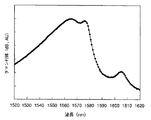
本発明の第5の実施例を以下に示す。図12のように、ある励起光波長に対するラマン利得プロファイルが分かっている場合、テスト光に対するラマン利得効率から他の波長のラマン利得効率を算出することができる。図12はSMFにおける励起光波長1463.8nmに対するラマン利得プロファイルを示している。ラマン利得プロファイルは、励起光出力パワーによって絶対値が変化するが、プロファイルの形はファイバ種類に固有のものである。図12のラマン利得プロファイルは1550nmで2.5dBのラマン利得を示しているが、1540nmでは2dBのラマン利得を示している。このラマン利得プロファイルの形状から1540nmのラマン利得効率は1550nmの2÷2.5=0.8倍であることがわかる。従って、実施例1と同一のSSMFにおいて励起波長を1463.8nmとした場合、第2の実施例の結果から、1550nmにおけるラマン利得効率は27.7dB/Wであるから、1540nmにおけるラマン利得効率は27.7×0.8=22.2dB/Wと算出することが出来る。
【0049】
また、本実施例では伝送路ファイバとしてSMFを用いたが、ノンゼロディスパージョンファイバ(Non Zero Dispersion Fiber:DSF)、1.55μmディスパージョンシフテッドファイバ(Dispersion Shifted Fiber:DSF)等の適用も可能である。
【0050】
<第6の実施例>
本発明の第6の実施例を以下に示す。1つのテスト光波長を用いて、複数の励起光それぞれの波長より13THz低い周波数の波長、即ちラマン利得プロファイルのピーク波長におけるラマン利得効率を得ることができる。ラマン利得プロファイルのピーク波長を、以下ではラマン利得ピーク波長と呼ぶ。第4の実施例の手法により、複数の励起波長に対する1つのテスト光波長におけるラマン利得効率を測定する。測定結果から、第5の実施例の手法により、各励起波長のラマン利得ピーク波長におけるラマン利得効率を算出する。もちろん、本実施例の手法で得られるラマン利得効率は、各励起波長のラマン利得ピーク波長のものに限られない。本実施例の手法により、分かっているラマン利得プロファイル内の任意の波長におけるラマン利得効率を得ることが出来る。
【0051】
【発明の効果】
本発明を用いることにより、伝送路の一方の端での作業のみで利得効率を測定することが可能となる。その結果、伝送路の両端の中継局間が数10km離れていることなどから、伝送路の両端で同時に作業を行うこと困難な場合においても、伝送路におけるラマン利得効率を得ることが出来る。
【0052】
本発明を用いることにより、1つのテスト光波長を用いて、複数種類の励起波長に対してそれぞれ所望の波長におけるラマン利得効率を得ることができる。結果として、複数種類の励起波長に対してそれぞれ所望の波長におけるラマン利得効率を得たい場合、励起波長の種類と同数の波長の異なるテスト光を用意する必要がなく、低コスト、かつ汎用性に富んだラマン利得効率測定が可能となる。
【図面の簡単な説明】
【図1】本発明のラマン利得及びラマン利得効率測定方法を示す構成図である。
【図2】従来のラマン利得及びラマン利得効率測定方法例の構成図である。
【図3】本発明の作用を示す伝送路におけるテスト光パワーの推移の説明図である。
【図4】本発明の作用を示す伝送路における戻り光パワーの推移の説明図である。
【図5】ラマン利得プロファイルを示す説明図である。
【図6】OTDRグラフにおける伝送路端の特徴を説明する図である。(a)B端が無反射終端されている場合、(b)B端で反射が発生している場合。
【図7】本発明の第1の実施例で得られる結果(OTDR)を示す説明図である。
【図8】本発明の第1の実施例の励起波長、テスト光波長、利得プロファイル波長配置を示す説明図である。
【図9】本発明の第2の実施例で得られる結果(OTDRグラフ)を示す説明図である。
【図10】本発明の第3の実施例の励起波長、テスト光波長、利得プロファイル波長配置を示す説明図である。
【図11】本発明の第4の実施例の励起波長、テスト光波長、利得プロファイル波長配置を示す説明図である。
【図12】本発明の第5の実施例の励起波長、テスト光波長、利得プロファイルを示す説明図である。
【符号の説明】
10、20 中継局
11、21 増幅器
110 OTDR
111,113 光増幅器
112 光ファイバ伝送路
114 WDMカプラ
115 光アッテネータ
116 波長フィルタ
113 WDMカプラ
120 テスト光源
130 受光器
140 励起光源[0001]
TECHNICAL FIELD OF THE INVENTION
The present invention relates to a method and an apparatus for measuring Raman gain and Raman gain efficiency of an optical fiber transmission line.
[0002]
[Prior art]
In recent years, with the development of low-loss optical fibers and wavelength bands using low-loss wavelength bands and the development of amplification techniques, long-distance transmission using optical fibers has been progressing. Further, in order to perform transmission at a lower cost and more efficiently, it is expected that low-loss repeaterless transmission will be realized in the future, and an optical fiber amplifier using the optical fiber transmission line itself as an amplification medium, such as EDFA, Application of a wider band optical amplification technology is also considered.
[0003]
In a communication system using such an optical fiber transmission line, development for commercialization of a technique called Distributed Raman Amplification (DRA) is progressing. Raman amplification means that when signal light and excitation light having a frequency higher than that of the signal light by about 13 THz are simultaneously input to an optical fiber made of silica glass, part of the energy of the excitation light is stimulated by the stimulated Raman scattering phenomenon in the silica glass. Is a phenomenon that shifts to the signal light, that is, the signal light is amplified. The gain due to Raman amplification is hereinafter referred to as Raman gain. Actually, the Raman gain has a wavelength dependence as shown in FIG. 5 with a peak at a wavelength 13 THz lower than the pump light. Hereinafter, this is called a Raman gain profile. FIG. 5 is an explanatory diagram showing a Raman gain profile.
[0004]
The distributed Raman amplification is a form in which pump light is input to an optical fiber for transmitting signal light, and a Raman amplification effect is obtained using the optical fiber transmission line itself as an amplification medium. In an optical fiber transmission system to which distributed Raman amplification is applied, the propagation loss in the transmission path is compensated by Raman amplification, so that the transmittable distance can be extended.
《Raman gain efficiency》
In the optical transmission system corresponding to the long-distance transmission, from the transmitting station, the signal light that has received a certain loss through the optical fiber transmission line, it is necessary to maintain a desired input level on the receiving side, conventionally, The receiving side measures the input level of the transmitted signal light, and sets and adjusts the power of the signal light of the transmitting station or the amplification factor in the relay transmission line.
[0005]
Hereinafter, a measurement method in a conventional optical transmission system will be described. Here, the gain efficiency of the optical fiber is used particularly for adjusting the input level of the signal light. The gain efficiency is used as a parameter indicating how much gain is obtained at the measurement point on the receiving side with respect to 1 W of the transmission light source power for each fiber. That is, when 1 W pump light is input to the amplification medium, the Raman gain (dB) received by the signal light propagating through the amplification medium is called Raman gain efficiency (dB / W). Raman gain efficiency varies from one fiber to another. The reason is that the Raman gain efficiency depends on the mode field diameter, the amount of GeO2 added, the absorption of water (OH), and the like, and these are different for each fiber type, manufacturer, manufacturing time, and lot. Because. Therefore, in order to control the gain received by the signal light in distributed Raman amplification in an optical fiber transmission system using an already installed optical fiber transmission line, the characteristics of the transmission line optical fiber and the loss characteristics in the relay station building are required. It is necessary to measure the on-site condition such as Raman gain efficiency.
《Raman gain efficiency measurement method》
Hereinafter, a conventional technique will be described with reference to the drawings. Conventionally, the measurement of the Raman gain efficiency of distributed Raman amplification using the transmission line itself as an amplification medium has been performed with a configuration as shown in FIG. FIG. 2 is a configuration diagram of a conventional Raman gain and Raman gain efficiency measuring method example. Light that receives Raman gain by pumping light in measuring Raman gain efficiency is called test light. A
[0006]
[Problems to be solved by the invention]
When measuring the Raman gain efficiency, the conventional method requires that a measuring instrument, a light source, and an operator be arranged at both ends of the transmission line to perform the work. There is a need for a means for measuring the gain efficiency only by working at the end of the method.
That is, when the above-described conventional method is used, for example, it is necessary to operate and operate the
[0007]
In addition, when it is desired to obtain Raman gain efficiency at a desired wavelength for each of a plurality of types of pump wavelengths, test light beams having the same number of different wavelengths as the types of pump wavelengths are required, and there have been problems in terms of cost and versatility. . Therefore, the present invention provides means for obtaining Raman gain efficiency at desired wavelengths for a plurality of types of pump wavelengths using one test light wavelength.
[0008]
[Means for Solving the Problems]
The present invention relates to a method and apparatus for measuring the Raman gain and Raman gain efficiency of an optical fiber transmission line for measuring the Raman amplification gain or Raman gain efficiency of an optical fiber transmission line supplied with pump light.
[0009]
The present invention is based on a measurement step of measuring the propagation loss of the optical fiber with the test light by the time domain light reflection method (OTDR) in a state where the pumping light is output and stopped, and based on a difference between the propagation losses in the two states. A calculating step of calculating a Raman gain of the optical fiber.
[0010]
In addition, for an optical fiber that transmits signal light by applying distributed Raman amplification, a pumping light adjusting step of adjusting pumping light output, and in a state where the pumping light is output and stopped, a propagation loss of the optical fiber is reflected in a time domain. A measurement step of measuring with a test light according to the method (OTDR);
A calculating step of calculating a Raman gain of the optical fiber based on a difference between the propagation losses in the two states.
[0011]
Furthermore, the measuring step further includes a step of calculating the Raman gain by dividing the calculated Raman gain by pumping light power.
[0012]
Further, the measuring step is characterized in that a propagation loss to one end of the optical fiber transmission line for inputting the test light and a measurement point near the other end is measured.
[0013]
Further, the measuring step is capable of measuring a propagation loss between one end of an optical fiber transmission line for inputting test light and an arbitrary return light generation point (measurement point) which is not affected by noise.
[0014]
Further, the frequency interval between the test light and the pump light is set to an arbitrary value capable of detecting a Raman gain profile gain.
[0015]
Further, a frequency interval between the test light and the excitation light is about 13 THz.
[0016]
Further, the present invention is characterized in that Raman gain or Raman gain efficiency is measured for one or more pump light wavelengths for one test light wavelength.
[0017]
The method is characterized by including a step of calculating a Raman gain or a Raman gain efficiency in test light different from a Raman gain profile for an arbitrary pump light and a Raman gain measurement value for an arbitrary test light.
[0018]
A measuring step of measuring Raman gain or Raman gain efficiency for one or more pumping light wavelengths for one test light wavelength; a Raman gain obtained in the measuring step; and a Raman gain profile obtained from the Raman gain profile. Calculating a Raman gain and a Raman gain efficiency at a gain peak wavelength.
[0019]
The measuring step includes an optical filter step for extracting a test light wavelength having a predetermined spectral width, and an optical attenuation step for measuring return light.
[0020]
The measuring step may further include a step of adjusting a pulse light spectrum width used as test light to a value that prevents saturation of the OTDR measurement light receiver.
[0021]
The measuring step further includes a step of adjusting a pulse light spectrum width used as the test light in order to detect a period of a change in the Raman gain profile.
[0022]
The pumping light adjusting step includes a step of adjusting the OTDR graph when the pumping light output is stopped and when the pumping light is output so that the OTDR graph can be regarded as parallel at a point (measurement point) where the test light returns.
The apparatus for measuring Raman gain and Raman gain efficiency of an optical fiber according to the present invention is a pump light adjusting unit that applies distributed Raman amplification to adjust pump light input to an optical fiber that transmits signal light, and is adjusted by the pump light adjusting unit. The propagation loss of the optical fiber is measured using OTDR (time domain light reflection) for the two states of input and stop of the pump light, and the Raman gain of the optical fiber is determined based on the difference between the propagation losses of the two states. And a measuring means having a Raman gain calculating step of calculating
[0023]
Further, an optical fiber for transmitting signal light by applying the distributed Raman amplification of the present invention, a pump light source capable of adjusting a pump light output, and inputting test light to the optical fiber and detecting return light. And measuring means for measuring the propagation loss of the optical fiber.
[0024]
Further, the loss measuring means is configured to include an OTDR measuring device for inputting test light input to the optical fiber and measuring return light power.
[0025]
Further, the loss measuring means further includes an optical filter for extracting a test light wavelength having a predetermined spectrum width from the output pulse light from the OTDR measuring device, and an optical attenuator for measuring return light.
[0026]
[Action]
In the present invention, Raman gain efficiency can be measured based on the OTDR measurement method. The propagation loss from one end of the transmission path to the other end is measured by the OTDR method. FIG. 3 shows a state in which the pulse light input from the end A reaches the vicinity before the end B while being attenuated. FIG. 4 shows a state in which return light generated in the vicinity of the end B is attenuated and reaches the end A. The loss reduced by the input of the pump light is considered to be the Raman gain. As shown in FIGS. 3 and 4, this Raman gain is the same as that of the pump light until the test light reaches near the B-end. Raman gain received while propagating in the direction: FIG. 3 and Raman gain received while propagating in the opposite direction to the pump light until the return light reaches the A end: FIG. The propagation loss (dB) detected from the return light generated near the B-end of the transmission path is set to L1, and OTDR measurement is performed with the pump light output. Assuming that the detected propagation loss (dB) is L2, the magnitude of the Raman gain does not depend on the propagation directions of the test light (return light) and the pump light, and therefore the value obtained by subtracting L1 from L2 is 倍. By doing so, it is possible to obtain the Raman gain received by the test light in the transmission path. By dividing the Raman gain by the pump light output power, the Raman gain efficiency (dB / W) at the OTDR pulse light wavelength can be calculated.
[0027]
Further, it is possible to obtain Raman gain efficiency at a desired wavelength for each of a plurality of types of excitation wavelengths from measurement using one test light wavelength. Raman gain efficiencies for a plurality of types of pump wavelengths are measured using one test light wavelength, and are converted into Raman gain efficiencies at desired wavelengths at each pump wavelength using a Raman gain profile.
[0028]
BEST MODE FOR CARRYING OUT THE INVENTION
Next, embodiments of the present invention will be described with reference to the drawings.
<First embodiment>
FIG. 1 is a configuration diagram showing the configuration of the present embodiment. In the configuration shown in FIG. 1, a
[0029]
In the present invention, in order to measure the Raman gain efficiency, an OTDR (Optical Time-Domain Reflectometry: time domain light reflection measurement)
[0030]
OTDR measures the distributional loss of an optical fiber transmission line by injecting pulsed light from one end of the optical fiber transmission line and time-divisionally measuring the return light due to backscattering occurring in the optical fiber transmission line. It is a technique to do. Since the detected pulse light power reciprocates between the incident end and the reflection point, if the amount of attenuation in the round trip is divided by half, the amount of attenuation is one-way.
[0031]
The causes of the return light include Fresnel reflection that occurs at the connection point or end point of the fiber and Rayleigh scattering that occurs continuously in the optical fiber. As shown in FIG. 1, the end of the transmission path to which the OTDR is connected is referred to as A end, and the other end is referred to as B end. FIGS. 6A and 6B show the return light power measured by the OTDR, and the horizontal axis represents the distance from the point A where the return light is generated. Hereinafter, such a graph is referred to as an OTDR graph. 6A and 6B, return light other than Rayleigh scattering does not occur in transmission paths other than the B-end. FIG. 6A shows a case where the B end is non-reflection-terminated by an isolator or the like, and the return light due to Rayleigh scattering becomes 0 at the end of the fiber. FIG. 6B shows a case where Fresnel reflection occurs at the B end due to discontinuity of the fiber, etc., where large reflection occurs at the end of the fiber, and the return light due to Rayleigh scattering becomes 0 at the end. I have. When the OTDR measurement is performed on the transmission path, the OTDR graph shows a characteristic as shown in FIG. Therefore, the distance from the end A to the end B can be known from such characteristics, and the loss of the pulsed light that has propagated from the end A to the vicinity immediately before the end B can be measured.
[0032]
In this embodiment, the spectrum width of the OTDR pulse light serving as the test light is particularly set to 1 nm. By setting the pass band of the optical filter for extracting the test light wavelength to 1 nm, amplified spontaneous emission (ASE) due to Raman amplification was removed, and saturation of the OTDR light receiver due to the ASE light was prevented. Further, the amount of the optical attenuator was adjusted so that the light receiver of the OTDR was not saturated and the return light generated near the B-end could be measured with high sensitivity.
[0033]
Next, the measurement procedure will be described. First, OTDR measurement is performed with the pump light output stopped, and a propagation loss (dB) (referred to as L1) detected from return light generated near the B-end of the transmission path is obtained. Next, OTDR measurement is performed in a state where the pumping light is output, and a propagation loss (dB) (referred to as L2) detected from the returning light generated near the B end of the transmission path is obtained. Raman gain is obtained by subtracting L1 from L2. By dividing the Raman gain by the pump light power, the Raman gain efficiency is obtained.
However, it is necessary that the pumping light power is sufficiently attenuated at the point B so that the Raman gain does not occur, that is, the OTDR graph when the pumping light output is stopped and the pumping light output are parallel. By calculating the propagation loss at point B that satisfies such conditions, the Raman gain that occurs over the entire length of the transmission path is determined. Further, by dividing the Raman gain by the pumping light power, the Raman gain efficiency over the entire length of the transmission path can be obtained.
[0034]
If the OTDR graphs at the point B when the optical pumping light output is stopped and when the pumping light output is not parallel, the pumping light power may be reduced until the OTDR graphs become parallel. In this embodiment, an 80 km single mode fiber (SMF) is used as the transmission line fiber, 1463.8 nm is used as the pumping light wavelength, and 1562.2 nm whose frequency is 13 THz lower than the pumping light wavelength is used as the test light wavelength. The output power was 166 mW. As a result, as shown in the OTDR graph of FIG. 7, L1 = 17 dB and L2 = 12 dB, and L2-L1 = 5.0 dB was obtained as the Raman gain. This was divided by the pump power to obtain a Raman gain efficiency of 30.1 dB / W. FIG. 8 shows the relationship between the excitation wavelength, the test light wavelength, and the Raman gain profile of this embodiment. In FIG. 8, the test light wavelength is located at the peak of the Raman gain profile with respect to the pump light.
[0035]
Further, in the present embodiment, the spectrum width of the test light is set to 1 nm, but application of a spectrum width different from this is also effective. However, considering the case where the OTDR measurement becomes unstable when the spectrum width is too narrow, the spectrum width should be wide enough not to make the OTDR measurement unstable and sufficiently narrow with respect to the period of the change of the Raman gain profile. Condition.
[0036]
In this embodiment, a DFB (Distributed Feed Back) laser is applied as the test light, but it is also effective to use a wavelength-tunable laser that can have a spectrum width under the above conditions. In this embodiment, an optical wavelength filter having a pass band of 1 nm is applied. However, as long as the spectrum of the test light is not cut out and ASE light can be sufficiently removed, application of a different pass band is also effective.
[0037]
In this embodiment, a dielectric multilayer film (Di-electric) type is applied to the optical wavelength filter, but the application of another device having an optical filtering function is also effective. For example, it is effective to apply a grating type wavelength filter, a Fabry-Perot type wavelength filter, a Mach-Zehnder interferometer type wavelength filter, or the like.
[0038]
Further, in the embodiment, the Mach-Zehnder interferometer type is applied to the optical attenuator, but the application of another device having an optical attenuation function is also effective. For example, a dielectric multilayer (Di-electric) type optical attenuator, an LN type attenuator, and an LBO type attenuator can be applied.
[0039]
Further, a Fabry-Perot laser whose wavelength is narrowed by a fiber grating is used as an excitation light source, but a tunable laser capable of outputting sufficient power is also effective. .
[0040]
In this embodiment, the SMF is used as the transmission line fiber. However, a non-zero dispersion shifted fiber (NZDSF), a 1.55 μm dispersion shifted fiber (Dispersion Shifted Fiber: DSF), or the like is applied. Is also possible.
[0041]
<Second embodiment>
Next, a second embodiment of the present invention will be described. In the first embodiment, Raman gain efficiency was obtained by using propagation loss detected from return light generated near the B-end of the transmission path. However, as shown in FIG. 9, in a transmission path having a large loss at the test light wavelength, the B end may not be detected due to noise in some cases. In such a case, it is also possible to obtain the gain efficiency from the return light generated at a point not buried in noise (point B 'in FIG. 9). However, it is necessary that the pumping light power is sufficiently attenuated at the point B ′ and Raman gain does not occur, that is, the OTDR graphs when the pumping light output is stopped and the pumping light output are parallel. If the OTDR graphs at the time of stopping the pumping light output and at the time of pumping light output do not become parallel at the point B ', the pumping light power may be reduced until they become parallel.
[0042]
FIG. 9 shows an OTDR graph in a case where an SMF whose propagation loss from the A-end to the B-end at the test wavelength is 40 dB is measured using the OTDR that can measure the return light generated at the point of the propagation loss of 30 dB. In this embodiment, as in the first embodiment, 1463.8 nm is used as the excitation light wavelength, 1562.2 nm whose frequency is 13 THz lower than the excitation light wavelength is used as the test light wavelength, and the output power of the excitation light is 166 mW. And Assuming that the propagation loss up to the point B ′ when the pumping light is stopped is L′ 1 and the propagation loss up to the point B ′ when the pumping light is output is L′ 2, as shown in FIG. 30 dB, L2 = 25.2 dB, and 4.8 dB was obtained as the Raman gain. This Raman gain was divided by the pump light power to obtain a Raman gain efficiency of 28.9 dB / W.
[0043]
Although the SMF is used as the transmission line fiber in the present embodiment, a non-zero dispersion shifted fiber (NZDSF), a 1.55 μm dispersion shifted fiber (Dispersion Shifted Fiber: DSF), or the like can be applied. It is.
[0044]
<Third embodiment>
A third embodiment of the present invention will be described. The first embodiment shows the Raman gain efficiency when the test light wavelength is 13 THz lower than the pump light frequency. However, the present invention is not limited to this, and the Raman gain efficiency can be measured at other wavelength intervals. For example, in the same SMF as the first embodiment, when the test light wavelength is 1550.0 nm, the pump light wavelength is 1463.8 nm, and the pump light output power is 166 mW, the Raman gain is 4.6 dB and the Raman gain efficiency is 27. 7 dB / W was obtained. FIG. 10 shows the relationship between the excitation wavelength, the test light source, and the Raman gain profile of the present embodiment.
[0045]
Although the SMF is used as the transmission line fiber in this embodiment, a non-zero dispersion fiber (DSF), a 1.55 μm dispersion-shifted fiber (Dispersion) is used.
Shifted Fiber (DSF) is also applicable.
[0046]
<Fourth embodiment>
Next, a fourth embodiment of the present invention will be described below. Using one test light wavelength, the Raman gain efficiency for a plurality of types of pump light wavelengths can be measured. For example, in the same SMF as the first embodiment, when the test light wavelength is 1550.0 nm, the pump light wavelength is 1463.8 nm, and the pump light output power is 166 mW, the Raman gain is 4.6 dB and the Raman gain efficiency is 27. 7 dB / W was obtained. Similarly, when the test wavelength was 1550.0 nm, the pump light wavelength was 1450.4 nm, and the pump light output power was 166 mW, a Raman gain of 5.1 dB and a Raman gain efficiency of 30.7 dB / W were obtained. Of course, the Raman gain efficiency for three or more pump light wavelengths can be measured using one test light wavelength, depending on how the test light wavelength is selected. FIG. 11 shows the relationship between the excitation wavelength, the test light source, and the Raman gain profile of the present embodiment.
[0047]
Although the SMF is used as the transmission line fiber in this embodiment, a non-zero dispersion fiber (DSF), a 1.55 μm dispersion-shifted fiber (Dispersion) is used.
Shifted Fiber (DSF) is also applicable.
[0048]
<Fifth embodiment>
A fifth embodiment of the present invention will be described below. As shown in FIG. 12, when the Raman gain profile for a certain pumping light wavelength is known, the Raman gain efficiency for another wavelength can be calculated from the Raman gain efficiency for the test light. FIG. 12 shows a Raman gain profile for an excitation light wavelength of 1463.8 nm in the SMF. The absolute value of the Raman gain profile changes depending on the pumping light output power, but the shape of the profile is specific to the type of fiber. The Raman gain profile in FIG. 12 shows a Raman gain of 2.5 dB at 1550 nm, but shows a Raman gain of 2 dB at 1540 nm. From the shape of the Raman gain profile, it can be seen that the Raman gain efficiency at 1540 nm is 2 ÷ 2.5 = 0.8
[0049]
In this embodiment, the SMF is used as the transmission line fiber. However, a non-zero dispersion fiber (DSF), a 1.55 μm dispersion shifted fiber (Dispersion Shifted Fiber: DSF), or the like can be applied. is there.
[0050]
<Sixth embodiment>
A sixth embodiment of the present invention will be described below. Using one test light wavelength, it is possible to obtain Raman gain efficiency at a wavelength at a frequency 13 THz lower than the wavelength of each of the plurality of pump lights, that is, at the peak wavelength of the Raman gain profile. The peak wavelength of the Raman gain profile is hereinafter referred to as a Raman gain peak wavelength. The Raman gain efficiency at one test light wavelength for a plurality of pump wavelengths is measured by the method of the fourth embodiment. From the measurement results, the Raman gain efficiency at the Raman gain peak wavelength of each pump wavelength is calculated by the method of the fifth embodiment. Of course, the Raman gain efficiency obtained by the method of the present embodiment is not limited to the Raman gain peak wavelength of each pump wavelength. According to the method of the present embodiment, it is possible to obtain the Raman gain efficiency at an arbitrary wavelength within the known Raman gain profile.
[0051]
【The invention's effect】
By using the present invention, it is possible to measure the gain efficiency only by working at one end of the transmission path. As a result, the Raman gain efficiency in the transmission line can be obtained even when it is difficult to work at both ends of the transmission line at the same time because the relay stations at both ends of the transmission line are separated by several tens of kilometers.
[0052]
By using the present invention, Raman gain efficiency at desired wavelengths can be obtained for a plurality of types of pump wavelengths using one test light wavelength. As a result, when it is desired to obtain Raman gain efficiency at a desired wavelength for each of a plurality of types of pump wavelengths, it is not necessary to prepare test lights having the same number of different wavelengths as the types of pump wavelengths. Abundant Raman gain efficiency measurements are possible.
[Brief description of the drawings]
FIG. 1 is a configuration diagram illustrating a method for measuring Raman gain and Raman gain efficiency according to the present invention.
FIG. 2 is a configuration diagram of a conventional Raman gain and Raman gain efficiency measuring method example.
FIG. 3 is an explanatory diagram of transition of test light power in a transmission line showing the operation of the present invention.
FIG. 4 is an explanatory diagram of the transition of the return light power in the transmission line showing the operation of the present invention.
FIG. 5 is an explanatory diagram showing a Raman gain profile.
FIG. 6 is a diagram illustrating characteristics of a transmission path end in an OTDR graph. (A) A case where the B end is non-reflection-terminated, and (b) a case where reflection occurs at the B end.
FIG. 7 is an explanatory diagram showing a result (OTDR) obtained in the first example of the present invention.
FIG. 8 is an explanatory diagram showing an excitation wavelength, a test light wavelength, and a gain profile wavelength arrangement according to the first embodiment of the present invention.
FIG. 9 is an explanatory diagram showing a result (OTDR graph) obtained in the second example of the present invention.
FIG. 10 is an explanatory diagram showing an excitation wavelength, a test light wavelength, and a gain profile wavelength arrangement according to a third embodiment of the present invention.
FIG. 11 is an explanatory diagram showing an excitation wavelength, a test light wavelength, and a gain profile wavelength arrangement according to a fourth embodiment of the present invention.
FIG. 12 is an explanatory diagram showing an excitation wavelength, a test light wavelength, and a gain profile according to a fifth embodiment of the present invention.
[Explanation of symbols]
10, 20 relay station
11, 21 Amplifier
110 OTDR
111,113 Optical amplifier
112 Optical fiber transmission line
114 WDM coupler
115 Optical Attenuator
116 wavelength filter
113 WDM coupler
120 test light source
130 receiver
140 Excitation light source
Claims (4)
前記光ファイバより入力した戻り光のパワーを測定する測定手段と、
前記光ファイバにおける他端において、前記光ファイバより入力した前記励起光により励起された光の戻り光である第1の戻り光と、前記励起光の出力が停止された状態の光の戻り光である第2の戻り光のパワーの比が一定となるよう、前記励起光のパワーを調整する調整手段と、
前記光ファイバより入力した前記第1の戻り光及び前記第2の戻り光のパワーに基づいて前記光ファイバにおける最大のラマン利得効率を算出するラマン利得効率算出手段と、
を備えることを特徴とする、ラマン増幅器。Means for outputting pump light having a power greater than 0 to one end of the optical fiber;
Measuring means for measuring the power of the return light input from the optical fiber,
At the other end of the optical fiber, a first return beam the light of the return light excited by pre Symbol excitation light inputted from the optical fiber, the return light when the output of the excitation light is stopped Adjusting means for adjusting the power of the pump light so that the power ratio of the second return light, which is light, is constant;
Raman gain efficiency calculation means for calculating the maximum Raman gain efficiency in the optical fiber based on the power of the first return light and the second return light input from the optical fiber,
A Raman amplifier, comprising:
テスト光を前記光ファイバに出力する手段と、
前記光ファイバより入力した戻り光のパワーを測定する測定手段と、
前記光ファイバにおける他端において、前記光ファイバより入力した前記励起光により励起された前記テスト光の戻り光である第1の戻り光と、前記励起光の出力が停止された状態の前記テスト光の戻り光である第2の戻り光のパワーの比が一定となるよう、前記励起光のパワーを調整する調整手段と、
前記光ファイバより入力した前記第1の戻り光及び前記第2の戻り光のパワーに基づいて前記光ファイバにおける最大のラマン利得効率を算出するラマン利得効率算出手段と、を備えることを特徴とする、ラマン増幅器。Means for outputting pump light having a power greater than 0 to one end of the optical fiber;
Means for outputting test light to the optical fiber;
Measuring means for measuring the power of the return light input from the optical fiber,
At the other end of the optical fiber, a first return beam that is the test return light excited by pre Symbol excitation light inputted from the optical fiber, the state in which the output of the excitation light is stopped Adjusting means for adjusting the power of the pumping light so that the ratio of the power of the second returning light, which is the returning light of the test light, is constant;
Raman gain efficiency calculating means for calculating the maximum Raman gain efficiency in the optical fiber based on the powers of the first return light and the second return light input from the optical fiber. , Raman amplifier.
前記光ファイバより入力した戻り光のパワーを測定する測定工程と、
前記光ファイバにおける他端において、前記光ファイバより入力した前記励起光により励起された光の戻り光である第1の戻り光と、前記励起光の出力が停止された状態の戻り光である第2の戻り光のパワーの比が一定となるよう、前記励起光のパワーを調整する調整工程と、
前記光ファイバより入力した前記第1の戻り光及び前記第2の戻り光のパワーに基づいて前記光ファイバにおける最大のラマン利得効率を算出するラマン利得効率算出工程と、
を備えることを特徴とするラマン増幅方法。 Outputting pump light having a power greater than 0 to one end of the optical fiber;
A measuring step of measuring the power of the return light input from the optical fiber,
At the other end of the optical fiber, a first return beam the light of the return light excited by pre Symbol excitation light inputted from the optical fiber, the return light of the state where the output of the excitation light is stopped An adjusting step of adjusting the power of the pumping light so that the power ratio of a certain second return light is constant;
A Raman gain efficiency calculating step of calculating a maximum Raman gain efficiency in the optical fiber based on the powers of the first return light and the second return light input from the optical fiber;
A Raman amplification method comprising:
テスト光を前記光ファイバに出力する工程と、
前記光ファイバより入力した戻り光のパワーを測定する測定工程と、
前記光ファイバにおける他端において、前記光ファイバより入力した前記励起光により励起された前記テスト光の戻り光である第1の戻り光と、前記励起光の出力が停止された状態の前記テスト光の戻り光である第2の戻り光のパワーの比が一定となるよう、前記励起光のパワーを調整する調整工程と、
前記光ファイバより入力した前記第1の戻り光及び前記第2の戻り光のパワーに基づいて前記光ファイバにおける最大のラマン利得効率を算出するラマン利得効率算出工程と、
を備えることを特徴とするラマン増幅方法。 Outputting pump light having a power greater than 0 to one end of the optical fiber;
Outputting test light to the optical fiber;
A measuring step of measuring the power of the return light input from the optical fiber,
At the other end of the optical fiber, a first return beam that is the test return light excited by pre Symbol excitation light inputted from the optical fiber, the state in which the output of the excitation light is stopped An adjusting step of adjusting the power of the pumping light so that the power ratio of the second returning light that is the returning light of the test light is constant;
A Raman gain efficiency calculating step of calculating a maximum Raman gain efficiency in the optical fiber based on the powers of the first return light and the second return light input from the optical fiber;
A Raman amplification method comprising:
Priority Applications (7)
| Application Number | Priority Date | Filing Date | Title |
|---|---|---|---|
| JP2001103070A JP3587176B2 (en) | 2001-04-02 | 2001-04-02 | Raman amplifier and Raman amplification method |
| CA2379434A CA2379434C (en) | 2001-04-02 | 2002-03-27 | Method and apparatus for measuring raman gain, method and apparatus for controlling raman gain, and raman amplifier |
| EP02007265A EP1248389B1 (en) | 2001-04-02 | 2002-03-28 | Method and apparatus for measuring Raman gain |
| US10/107,392 US6738132B2 (en) | 2001-04-02 | 2002-03-28 | Method and apparatus for measuring Raman gain, method and apparatus for controlling Raman gain, and Raman amplifier |
| DE60229993T DE60229993D1 (en) | 2001-04-02 | 2002-03-28 | Method and apparatus for measuring Raman amplification |
| CNB021087989A CN100354744C (en) | 2001-04-02 | 2002-04-02 | Method and dvice for measuring and controlling Raman gain and Raman amplifier |
| US10/761,264 US6934016B2 (en) | 2001-04-02 | 2004-01-22 | Method and apparatus for measuring Raman gain, method and apparatus for controlling Raman gain, and Raman amplifier |
Applications Claiming Priority (1)
| Application Number | Priority Date | Filing Date | Title |
|---|---|---|---|
| JP2001103070A JP3587176B2 (en) | 2001-04-02 | 2001-04-02 | Raman amplifier and Raman amplification method |
Related Child Applications (1)
| Application Number | Title | Priority Date | Filing Date |
|---|---|---|---|
| JP2004152906A Division JP3952039B2 (en) | 2004-05-24 | 2004-05-24 | Measuring device, optical transmission system, and Raman gain measuring method |
Publications (2)
| Publication Number | Publication Date |
|---|---|
| JP2002296145A JP2002296145A (en) | 2002-10-09 |
| JP3587176B2 true JP3587176B2 (en) | 2004-11-10 |
Family
ID=18956182
Family Applications (1)
| Application Number | Title | Priority Date | Filing Date |
|---|---|---|---|
| JP2001103070A Expired - Fee Related JP3587176B2 (en) | 2001-04-02 | 2001-04-02 | Raman amplifier and Raman amplification method |
Country Status (6)
| Country | Link |
|---|---|
| US (2) | US6738132B2 (en) |
| EP (1) | EP1248389B1 (en) |
| JP (1) | JP3587176B2 (en) |
| CN (1) | CN100354744C (en) |
| CA (1) | CA2379434C (en) |
| DE (1) | DE60229993D1 (en) |
Families Citing this family (38)
| Publication number | Priority date | Publication date | Assignee | Title |
|---|---|---|---|---|
| JP4588257B2 (en) * | 2001-06-27 | 2010-11-24 | 富士通株式会社 | Optical amplification system using Raman amplification |
| JP3578343B2 (en) * | 2001-10-31 | 2004-10-20 | 日本電気株式会社 | Optical fiber transmission system, Raman gain efficiency measuring apparatus and Raman gain efficiency measuring method |
| US8750702B1 (en) * | 2002-06-21 | 2014-06-10 | Rockstar Consortium Us Lp | Passive optical loopback |
| US20040095569A1 (en) * | 2002-11-20 | 2004-05-20 | Kan Clarence Kwok-Yan | Use of linear scattering losses to characterize amplified fiber spans |
| JP4318938B2 (en) * | 2003-03-13 | 2009-08-26 | 富士通株式会社 | Optical amplifier with splice loss detection function |
| DE602004001078T2 (en) | 2003-03-13 | 2007-01-25 | Fujitsu Ltd., Kawasaki | Optical amplifier with control functions of the pump light, and optical transmission system using this amplifier |
| JP4182797B2 (en) | 2003-04-17 | 2008-11-19 | Kddi株式会社 | Raman gain measuring device |
| CN1303469C (en) * | 2003-06-04 | 2007-03-07 | 清华大学 | Dynamic Feedback Control Method of Power and Gain Spectrum of Fiber Raman Amplifier |
| US7554721B2 (en) | 2003-08-01 | 2009-06-30 | Fujitsu Limited | Raman amplifier and Raman amplifier adjustment method |
| EP1522840A1 (en) * | 2003-11-13 | 2005-04-13 | Alcatel | Method and apparatus for determining the gain characteristic of a distributed raman amplifier |
| WO2006002689A1 (en) * | 2004-07-07 | 2006-01-12 | Agilent Technologies, Inc. | Optical time domain reflectometry system at different wavelengths |
| JP2006287649A (en) * | 2005-03-31 | 2006-10-19 | Nec Corp | Optical signal transmission power adjusting device in optical transmission system and optical signal transmission power adjusting method |
| EP1916565B1 (en) | 2005-06-20 | 2013-01-02 | Fujitsu Ltd. | Raman light amplifier |
| US7916384B2 (en) * | 2006-05-02 | 2011-03-29 | At&T Intellectual Property Ii, L.P. | Feedback dynamic gain control for a WDM system employing multi wavelength pumped Raman fiber amplifiers |
| GB2443661B (en) | 2006-11-08 | 2011-08-31 | Polarmetrix Ltd | Detecting a disturbance in the phase of light propogating in an optical waveguide |
| CN101079668B (en) * | 2007-07-05 | 2011-07-20 | 华为技术有限公司 | Device, method and device for positioning the optical fiber failure |
| JP2009276287A (en) * | 2008-05-16 | 2009-11-26 | Kansai Electric Power Co Inc:The | Raman gain efficiency measurement method and device |
| CN102725978B (en) * | 2009-12-03 | 2015-08-12 | 瑞典爱立信有限公司 | Improvement in optic network |
| US8643941B2 (en) * | 2009-12-14 | 2014-02-04 | Finisar Israel Ltd. | Automatic measurement and gain control of distributed Raman amplifiers |
| CN102307068B (en) | 2011-06-24 | 2015-04-01 | 武汉光迅科技股份有限公司 | Method for locking Raman gains of target and Raman OFA (optical fiber amplifier) |
| WO2013134394A1 (en) * | 2012-03-06 | 2013-09-12 | Adtran, Inc. | Systems and methods for reducing thermal tails on optical time domain reflectometer (otdr) measurements |
| GB2503497A (en) | 2012-06-29 | 2014-01-01 | Oclaro Technology Ltd | Determining a parameter of an optical fibre using a pump light source of an amplifier |
| CN102799044B (en) * | 2012-09-06 | 2015-04-29 | 杭州欧忆光电科技有限公司 | Method and device for amplifying signal light of optical time-domain reflectometer of fusion Raman amplifier |
| US9148710B2 (en) * | 2012-09-19 | 2015-09-29 | Ciena Corporation | Raman amplifier system and method with integrated optical time domain reflectometer |
| CN103048305A (en) * | 2012-12-07 | 2013-04-17 | 中国科学院西安光学精密机械研究所 | All-fiber laser Raman testing device |
| US9831943B2 (en) * | 2013-12-17 | 2017-11-28 | Neptune Subsea Ip Limited | Repeater OTDR using repeater based raman pumps |
| EP3096181B1 (en) * | 2014-01-16 | 2018-12-05 | Mitsubishi Electric Corporation | Excitation light source device and optical transmission system |
| CN110676679B (en) * | 2014-07-04 | 2022-08-09 | 古河电气工业株式会社 | Optical fiber laser device |
| US9503181B2 (en) * | 2015-01-06 | 2016-11-22 | Ii-Vi Incorporated | Rare earth-doped fiber amplifier with integral optical metrology functionality |
| EP3324169A1 (en) * | 2016-11-22 | 2018-05-23 | Xieon Networks S.à r.l. | Detection of gainers and exaggerated losses in unidirectional otdr traces |
| JP7006537B2 (en) * | 2018-08-16 | 2022-02-10 | 日本電信電話株式会社 | Raman gain efficiency distribution test method and Raman gain efficiency distribution test equipment |
| JP7259431B2 (en) * | 2019-03-15 | 2023-04-18 | 富士通オプティカルコンポーネンツ株式会社 | Optical device, optical module using same, and test method for optical device |
| US20220187163A1 (en) * | 2019-03-27 | 2022-06-16 | Nec Corportation | Light-transmission-path-spectrum measurement device, light-transmission-path system, and computer-readable medium |
| WO2020250305A1 (en) * | 2019-06-11 | 2020-12-17 | 日本電信電話株式会社 | Optical communication system and optical communication method |
| JP7492155B2 (en) * | 2020-05-28 | 2024-05-29 | 日本電信電話株式会社 | Optical amplification estimation method, optical amplification estimation device, and computer program |
| CN112582867B (en) * | 2020-12-03 | 2022-04-01 | 太原理工大学 | A Forward Brillouin Fiber Laser Based on Stimulated Raman-like |
| CN114166817A (en) * | 2021-11-22 | 2022-03-11 | 国网福建省电力有限公司 | Method for rapidly, qualitatively and quantitatively analyzing trace chloride ions |
| US11671172B1 (en) * | 2022-02-25 | 2023-06-06 | Huawei Technologies Co., Ltd. | Systems and methods for characterizing an optical fiber in a dense wavelength division multiplexing optical link |
Family Cites Families (14)
| Publication number | Priority date | Publication date | Assignee | Title |
|---|---|---|---|---|
| US5062704A (en) * | 1990-04-25 | 1991-11-05 | Tektronix, Inc. | Optical time domain reflectometer having pre and post front panel connector testing capabilities |
| JPH04274724A (en) * | 1991-03-02 | 1992-09-30 | Fujikura Ltd | Otdr apparatus |
| JP3124184B2 (en) | 1994-05-20 | 2001-01-15 | 株式会社フジクラ | Optical fiber temperature distribution measurement method |
| JP3403288B2 (en) | 1996-02-23 | 2003-05-06 | 古河電気工業株式会社 | Optical amplifier |
| JP3465733B2 (en) * | 1996-08-08 | 2003-11-10 | 日本電信電話株式会社 | Optical pulse test method |
| US6081323A (en) * | 1997-02-27 | 2000-06-27 | The United States Of America As Represented By The Director Of The National Security Agency | Measurement of Raman gain spectrum in optical fiber |
| JPH10336106A (en) * | 1997-05-28 | 1998-12-18 | Ando Electric Co Ltd | Otdr measurement instrument |
| US6067149A (en) * | 1998-12-14 | 2000-05-23 | Lucent Technologies | Dispersion-map measurements of optical fibers |
| US6519026B1 (en) * | 1999-08-06 | 2003-02-11 | Lucent Technologies Inc. | Optical time-domain reflectometer (OTDR) |
| US6452716B1 (en) * | 2000-10-05 | 2002-09-17 | Nortel Networks Limited | Amplitude modulation of a pump laser signal in a distributed raman amplifier |
| JP4576716B2 (en) | 2001-01-05 | 2010-11-10 | 住友電気工業株式会社 | Raman gain coefficient measurement method |
| US6417958B1 (en) * | 2001-01-24 | 2002-07-09 | Lucent Technologies Inc. | WDM optical communication system using co-propagating Raman amplification |
| JP3623742B2 (en) | 2001-02-23 | 2005-02-23 | 日本電信電話株式会社 | Method and apparatus for evaluating Raman amplifier |
| US6433922B1 (en) * | 2001-02-26 | 2002-08-13 | Redc Optical Networks Ltd. | Apparatus and method for a self adjusting Raman amplifier |
-
2001
- 2001-04-02 JP JP2001103070A patent/JP3587176B2/en not_active Expired - Fee Related
-
2002
- 2002-03-27 CA CA2379434A patent/CA2379434C/en not_active Expired - Fee Related
- 2002-03-28 DE DE60229993T patent/DE60229993D1/en not_active Expired - Lifetime
- 2002-03-28 US US10/107,392 patent/US6738132B2/en not_active Expired - Lifetime
- 2002-03-28 EP EP02007265A patent/EP1248389B1/en not_active Expired - Lifetime
- 2002-04-02 CN CNB021087989A patent/CN100354744C/en not_active Expired - Fee Related
-
2004
- 2004-01-22 US US10/761,264 patent/US6934016B2/en not_active Expired - Fee Related
Also Published As
| Publication number | Publication date |
|---|---|
| EP1248389B1 (en) | 2008-11-26 |
| US6738132B2 (en) | 2004-05-18 |
| CA2379434A1 (en) | 2002-10-02 |
| US6934016B2 (en) | 2005-08-23 |
| CN1379279A (en) | 2002-11-13 |
| DE60229993D1 (en) | 2009-01-08 |
| CN100354744C (en) | 2007-12-12 |
| CA2379434C (en) | 2010-04-27 |
| EP1248389A3 (en) | 2003-08-13 |
| EP1248389A2 (en) | 2002-10-09 |
| US20040160664A1 (en) | 2004-08-19 |
| US20020140927A1 (en) | 2002-10-03 |
| JP2002296145A (en) | 2002-10-09 |
Similar Documents
| Publication | Publication Date | Title |
|---|---|---|
| JP3587176B2 (en) | Raman amplifier and Raman amplification method | |
| US6433922B1 (en) | Apparatus and method for a self adjusting Raman amplifier | |
| US8068275B2 (en) | Method for measuring nonlinear optical properties | |
| US7595865B2 (en) | Optical time domain reflectometry for two segment fiber optic systems having an optical amplifier therebetween | |
| US6850360B1 (en) | Raman amplifier systems with diagnostic capabilities | |
| US11139633B2 (en) | In-situ fiber characterization using nonlinear skirt measurement | |
| US7408146B2 (en) | Signal light transmitting apparatus, signal light transmitting system using the same, and signal light transmitting method | |
| JP3578343B2 (en) | Optical fiber transmission system, Raman gain efficiency measuring apparatus and Raman gain efficiency measuring method | |
| JP3411436B2 (en) | Monitoring method of optical communication line | |
| US6687426B1 (en) | Out of band fiber characterization using optical amplifier light sources | |
| CN101304285B (en) | Optical amplifier provided with control function of pumping light, and optical transmission system using the same | |
| Wuilpart et al. | Distributed measurement of Raman gain spectrum in concatenations of optical fibres with OTDR | |
| JP3952039B2 (en) | Measuring device, optical transmission system, and Raman gain measuring method | |
| US20050196175A1 (en) | Method and apparatus for obtaining status information concerning an in-service optical transmission line | |
| Zheng et al. | Measurement and system impact of multipath interference from dispersion compensating fiber modules | |
| JP2002250674A (en) | Evaluation method and evaluation device for raman amplifier | |
| US11876559B2 (en) | Optical transmission system and fiber type determination method | |
| JP2009068877A (en) | Method and apparatus for evaluating Raman gain efficiency distribution in single mode optical fiber transmission line | |
| KR20030065144A (en) | Fiber Raman amplifier | |
| GB2393598A (en) | Bypass path for optical loss measurement signals |
Legal Events
| Date | Code | Title | Description |
|---|---|---|---|
| A02 | Decision of refusal |
Free format text: JAPANESE INTERMEDIATE CODE: A02 Effective date: 20030729 |
|
| A131 | Notification of reasons for refusal |
Free format text: JAPANESE INTERMEDIATE CODE: A131 Effective date: 20031224 |
|
| A521 | Written amendment |
Free format text: JAPANESE INTERMEDIATE CODE: A523 Effective date: 20040223 |
|
| A131 | Notification of reasons for refusal |
Free format text: JAPANESE INTERMEDIATE CODE: A131 Effective date: 20040323 |
|
| A521 | Written amendment |
Free format text: JAPANESE INTERMEDIATE CODE: A523 Effective date: 20040524 |
|
| A01 | Written decision to grant a patent or to grant a registration (utility model) |
Free format text: JAPANESE INTERMEDIATE CODE: A01 Effective date: 20040706 |
|
| TRDD | Decision of grant or rejection written | ||
| A01 | Written decision to grant a patent or to grant a registration (utility model) |
Free format text: JAPANESE INTERMEDIATE CODE: A01 Effective date: 20040727 |
|
| A61 | First payment of annual fees (during grant procedure) |
Free format text: JAPANESE INTERMEDIATE CODE: A61 Effective date: 20040719 |
|
| R150 | Certificate of patent or registration of utility model |
Free format text: JAPANESE INTERMEDIATE CODE: R150 |
|
| FPAY | Renewal fee payment (event date is renewal date of database) |
Free format text: PAYMENT UNTIL: 20070820 Year of fee payment: 3 |
|
| FPAY | Renewal fee payment (event date is renewal date of database) |
Free format text: PAYMENT UNTIL: 20080820 Year of fee payment: 4 |
|
| FPAY | Renewal fee payment (event date is renewal date of database) |
Free format text: PAYMENT UNTIL: 20080820 Year of fee payment: 4 |
|
| FPAY | Renewal fee payment (event date is renewal date of database) |
Free format text: PAYMENT UNTIL: 20090820 Year of fee payment: 5 |
|
| FPAY | Renewal fee payment (event date is renewal date of database) |
Free format text: PAYMENT UNTIL: 20090820 Year of fee payment: 5 |
|
| FPAY | Renewal fee payment (event date is renewal date of database) |
Free format text: PAYMENT UNTIL: 20100820 Year of fee payment: 6 |
|
| FPAY | Renewal fee payment (event date is renewal date of database) |
Free format text: PAYMENT UNTIL: 20110820 Year of fee payment: 7 |
|
| FPAY | Renewal fee payment (event date is renewal date of database) |
Free format text: PAYMENT UNTIL: 20110820 Year of fee payment: 7 |
|
| FPAY | Renewal fee payment (event date is renewal date of database) |
Free format text: PAYMENT UNTIL: 20120820 Year of fee payment: 8 |
|
| FPAY | Renewal fee payment (event date is renewal date of database) |
Free format text: PAYMENT UNTIL: 20130820 Year of fee payment: 9 |
|
| LAPS | Cancellation because of no payment of annual fees |