JP3541045B2 - Storage case for disk-shaped recording media - Google Patents
Storage case for disk-shaped recording media Download PDFInfo
- Publication number
- JP3541045B2 JP3541045B2 JP34636791A JP34636791A JP3541045B2 JP 3541045 B2 JP3541045 B2 JP 3541045B2 JP 34636791 A JP34636791 A JP 34636791A JP 34636791 A JP34636791 A JP 34636791A JP 3541045 B2 JP3541045 B2 JP 3541045B2
- Authority
- JP
- Japan
- Prior art keywords
- disk
- shaped recording
- storage case
- holder
- recording medium
- Prior art date
- Legal status (The legal status is an assumption and is not a legal conclusion. Google has not performed a legal analysis and makes no representation as to the accuracy of the status listed.)
- Expired - Fee Related
Links
Images


Classifications
-
- G—PHYSICS
- G11—INFORMATION STORAGE
- G11B—INFORMATION STORAGE BASED ON RELATIVE MOVEMENT BETWEEN RECORD CARRIER AND TRANSDUCER
- G11B33/00—Constructional parts, details or accessories not provided for in the other groups of this subclass
- G11B33/02—Cabinets; Cases; Stands; Disposition of apparatus therein or thereon
- G11B33/04—Cabinets; Cases; Stands; Disposition of apparatus therein or thereon modified to store record carriers
- G11B33/0405—Cabinets; Cases; Stands; Disposition of apparatus therein or thereon modified to store record carriers for storing discs
- G11B33/0433—Multiple disc containers
- G11B33/0438—Multiple disc containers for disc cartridges
Landscapes
- Packaging For Recording Disks (AREA)
- Packaging Of Annular Or Rod-Shaped Articles, Wearing Apparel, Cassettes, Or The Like (AREA)
Description
【0001】
【産業上の利用分野】
この発明は、フロッピーディスク等のディスク状記録媒体を収納するケースに関する。
【0002】
【従来の技術】
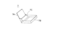
例えば、フロッピーディスク等のディスク状記録媒体の収納ケースとしては、図14に示すようなものがある。つまり、収納ケース7は一対の蓋7Aおよび7Bを備えている。そして、一対の蓋7Aおよび7Bはヒンジ部を中心にして回動可能となっており、一枚のフロッピーディスクが蓋7Aに形成された収納部7Cに収納され、蓋7Aと7Bとが閉じられる。この収納ケース7は、比較的に強度が高いポリスチレンやアクリルスチロール(曲げ弾性率約35000Kg/cm2)が使用されている。
【0003】
これに対し、ファッション性や密閉性等を考慮した、柔軟性が高い材質、例えばポリプロピレン(曲げ弾性率10000〜13000Kg/cm2)が使用された収納ケースもある。
【0004】
図15は、上記柔軟性が高い材質を使用した収納ケース8の概略図である。この収納ケース8は一対の蓋8Aおよび8Bを備えており、この一対の蓋8Aおよび8Bはヒンジ部を中心にして回動可能となっている。そして、この収納ケース8は、フロッピーディスクFが2枚収納できるようになっている。
【0005】
【発明が解決しようとする課題】
ところで、最近ノート型パーソナルコンピュータ等の普及により、フロッピーディスクなどのディスク状記録媒体の需要が増加している。そして、ディスク状記録媒体の需要増に伴って、ディスク状記録媒体の収納ケースの需要も増加している。さて、例えばノート型パーソナルコンピュータの場合には、持ち運び用にバックアップ用のフロッピーディスクとデータ用のフロッピーディスクとで最低2枚のフロッピーディスクが必要となるが、3枚以上のフロッピーディスクを用意しておくことが望ましい。
【0006】
ところで、持ち運びに便利な収納ケースとしては、従来最大で2枚のフロッピーディスクしか収納できない。したがって、3枚以上のフロッピーディスクを持ち運ぶ場合には、収納ケースを2つ以上用意しなければならず不便であった。
【0007】
そこで、3枚以上のフロッピーディスク等のディスク状記録媒体を収納し得る、持ち運びに便利な収納ケースが望まれていた。
【0008】
【課題を解決するための手段】
この発明のディスク状記録媒体の収納ケースは、上記間題点を解決するため、内面にディスク状記録媒体を保持する上蓋と、内面にディスク状記録媒体を保持する下蓋と、上記上蓋の一側部および上記下蓋の一側部とにヒンジ部を介して取り付けられた背面部材と、上記背面部材の内面側に配置されたホルダと、を備えていて、
上記ホルダは、ディスク状記録媒体の一端部を挿入することにより、該一端部のの表裏面を挟んでディスク状記録媒体を挟着保持する。
【0009】
【作用】
収納ケースの上蓋および下蓋のそれぞれに一枚ずつディスク状記録媒体が保持可能となっているとともに、上記ホルダに一枚または一枚以上のディスク状記録媒体が保持可能となっている。したがって、3枚以上のディスク状記録媒体を収納し得る持ち運びに便利な収納ケースが実現される。
【0010】
【実施例】
図1は、この発明の一実施例であるフロッピーディスクの収納ケース1の概略斜視図である。
【0011】
図1において、1Aは上蓋、1Bは下蓋、1Cは背面部であり、この背面部1Cは上蓋1Aの一側面と下蓋1Bの一側面とに、ヒンジ部を介して接続されている。また、1Dはホルダであり、このホルダ1Dは背面部1C上に配置されている。このホルダ1Dは、後述するように、平行した2つの側面部1Da,1Dbを備えており、この2つの側面部1Da,1Dbの間にフロッピーディスクF3が挟み込まれて保持されるようになっている。また、上蓋1Aの内面には、フロッピーディスクF1が保持されるようになっている。さらに、同様に、下蓋1Bの内面には、フロッピーディスクF2が保持されるようになっている。
【0012】
図2は、上記収納ケース1にフロッピーディスクF1,F2,F3が収納された状態の概略断面図である。この図2に示すように、上蓋1AにフロッピーディスクF1が保持され、下蓋1BにフロッピーディスクF2が保持される。そしてホルダ1DにフロッピーディスクF3が保持されている。
【0013】
図3および図4は、ホルダ1Dの部分拡大図である。図3および図4において、ホルダ1Dの側面部1Daと1Dbとの間の距離Tは、フロッピーディスクF3の厚みよりも僅かに小となっている。例えば、3.5インチのフロッピーディスクの場合、厚さは約3.3mmであり、この場合、距離Tは約3.0mmとする。また、ホルダ1Dの底面部1Dcには突起1Ddが形成されている。この突起1Ddの側面部1Dbおよび1Daからの距離T1およびT2は、それぞれ約1.0mmとなっている(3.5インチのフロッピーディスクの場合)。この突起1Ddは、フロッピーディスクF3に形成された半円形の切欠2に挿入されるようになっており、フロッピーディスクF3のホルダ1Dへの位置決め用である。なお、フロッピーディスクF3に形成された切欠2は、フロッピーディスクがディスクドライブ装置(図示せず)に挿入される際の位置決め用の切欠である。
【0014】
なお、上述した一実施例は、例えばポリプロピレン等の軟質の材料を用い、射出成形によって、上蓋1A,下蓋1B,背面部1C,ホルダ1D等が一体に形成される。
【0015】
以上のように、この発明の一実施例によれば、3枚以上のフロッピーディスクを収納し得る持ち運びに便利な収納ケースを実現することができる。
【0016】
図5は、この発明の他の実施例であるフロッピーディスクの収納ケース3の概略斜視図である。
【0017】
図5において、上蓋3Aの一側面と下蓋3Bの一側面とにヒンジ部を介して背面部3Cが接続されている。また、ホルダ3Dは背面部3C上に配置されており、互いに平行な3つの側面部、つまり上蓋側側面部,中間側面部,下蓋側側面部を備えている。そして、上蓋側側面部と中間側面部との間、および下蓋側側面部と中間側面部との間のそれぞれに1枚づつのフロッピーディスクを保持し得るように構成されている。
【0018】
この図5の例においては、4枚のフロッピーディスクを収納し得るように構成されている。
【0019】
図6は、この発明のさらに他の実施例であるフロッピーディスクの収納ケース4の概略斜視図である。
【0020】
図6において、上蓋4Aの一側面と下蓋4Bの一側面とにヒンジ部を介して背面部4Cが接続されている。また、ホルダ4Dは背面部4C上に配置されており、互いに平行な6つの側面部を備えている。そして、これら6つの側面部の隣接する側面部の間にそれぞれ1枚づつのフロッピーディスクを保持し得るように構成されている。
【0021】
この図6の例においては、7枚のフロッピーディスクを収納し得るように構成されている。
【0022】
図7,図8,図9は、この発明のさらに他の実施例である収納ケース5の展開図であり、図7は内面側、図8は外面側、図9は側面側から見た図である。
【0023】
図7,図8,図9において、5Aは上蓋、5Bは下蓋、5Cは背面部であり、この背面部5Cは上蓋5Aの一側面と下蓋5Bの一側面とに、ヒンジ部を介して接続されている。また、5Dはホルダであり、このホルダ5Dは背面部5C上に配置されている。そして、このホルダ5Dは、互いに平行な2つの側面部5Daおよび5Dbを備えている。なお、図示していないが上記側面部5Daと5Dbとの間には、図3および図4に示した突起1Ddと同様な突起が形成されている。そして、2つの側面部5Daと5Dbとの間の寸法は、フロッピーディスクの厚み(例えば約3.3mm)よりも僅かに小さな値となっている(例えば約3.0mm)。
【0024】
また、上蓋5Aの内面には、4つの保持用突起9,10,11,12が形成されており、これら4つの保持用突起9,10,11,12によってフロッピーディスクが保持されるようになっている。さらに、同様に、下蓋5Bの内面には、4つの保持用突起13,14,15,16が形成されており、これら4つの保持用突起13,14,15,16によってフロッピーディスクが保持されるようになっている。
【0025】
図10は、収納ケース5の上蓋5Aおよび下蓋5Bを閉じた状態の一部破断図であり、図11は両蓋5Aおよび5Bを閉じた状態の斜視図である。
【0026】
図12は、収納ケース5にフロッピーディスクF1,F2,F3が収納された状態の概略断面図である。この図12に示すように、上蓋5Aに保持されたフロッピーディスクF1は、ホルダ5Dの側面部5Daの上端側に配置され、下蓋5Bに保持されたフロッピーディスクF2は、ホルダ5Dの側面部5Dbの上端側に配置され、3枚のフロッピーディスクF1,F2,F3は密接して配置されている。つまり、収納ケース5の場合は、図2の例と比較して、側面部5Daの厚み寸法と側面部5Dbの厚み寸法分だけ、薄形化されている。
【0027】
以上のように、図7〜図12に示した実施例によれば、3枚のフロッピーディスクを収納でき、薄形化された持ち運びに便利な収納ケースを実現することができる。
【0028】
図13は、この発明のさらに他の実施例である収納ケース6の概略斜視図である。
【0029】
同図において、上蓋6Aの一側面と下蓋6Bの一側面とにヒンジ部を介して背面部6Cが接続されている。また、ホルダ6Dは背面部6C上に配置されており、互いに平行な側面部6Daと6Dbとを備えている。この側面部6Daと6Dbとの間の寸法は、1枚のフロッピーディスクの厚み寸法の2倍よりも僅かに小さなものとなっている。つまり、これら側面部6Daと6Dbとは2枚のフロッピーディスクを挟み込んで保持できるようになっている。また、上蓋6Aの内面には、4つの保持用突起9,10,11,12が形成されており、これら4つの保持用突起9,10,11,12によってフロッピーディスクが保持されるようになっている。さらに、下蓋6Bの内面には、4つの保持用突起13,14,15,16が形成されており、これら4つの保持用突起13,14,15,16によってフロッピーディスクが保持されるようになっている。そして、収納ケース6が閉じられた状態においては、図12と同様に、上蓋6Aに保持されたフロッピーディスクは側面部6Daの上端部に配置するようになっている。また、下蓋6Bに保持されたフロッピーディスクは側面部6Dbの上端部に配置するようになっている。つまり、4枚のフロッピーディスクは密接して収納ケース6内に収納される。したがって、図13の収納ケース6の場合は、4枚のフロッピーディスクを収納し得る図5の収納ケース3と比較して、ホルダ3Dの厚み寸法だけ薄形化される。
【0030】
なお、図5〜図13の例において、ホルダ3D,4D,5D,6Dには、図3および図4に示した突起1Ddと同様な突起が形成されている。
【0031】
また、上述した図1〜図13の例において、ポリプロピレン等の軟質の材料を用い、上蓋,下蓋,背面部およびホルダを射出成形により一体成形してもよい。さらに、ホルダのみ別個に成形し、この成形したホルダを背面部に超音波溶着等により接合してもよい。
【0032】
また、上述した実施例は、フロッピーディスクの収納ケースであるが、この発明は、フロッピーディスクのみならず、他のディスク状記録媒体の収納ケースにも適用することができる。
【0033】
【発明の効果】
以上のように、この発明によれば、内面にディスク状記録媒体を保持する上蓋と、内面にディスク状記録媒体を保持する下蓋と、上記上蓋の一側部および上記下蓋の一側部とにヒンジ部を介して取り付けられた背面部材と、上記背面部材の内面側に配置され、ディスク状記録媒体の表裏面を挟み込んで保持可能なホルダと、を備えるように構成したので、3枚以上のディスク状記録媒体を収納し得る持ち運びに便利な収納ケースを実現できる。
【図面の簡単な説明】
【図1】この発明の一実施例の概略斜視図。
【図2】この発明の一実施例の概略断面図。
【図3】この発明の一実施例におけるホルダの部分拡大図。
【図4】この発明の一実施例におけるホルダの部分拡大図。
【図5】この発明の他の実施例の概略斜視図。
【図6】この発明のさらに他の実施例の概略斜視図。
【図7】この発明のさらに他の実施例の内面部の展開図。
【図8】図7の例の外面部の展開図。
【図9】図7の例の側面部の展開図。
【図10】図7の例の閉じた状態の一部破断図。
【図11】図7の例の閉じた状態の斜視図。
【図12】図7の例の閉じた状態の概略断面図。
【図13】この発明のさらに他の実施例の概略斜視図。
【図14】従来の収納ケースの一例の概略斜視図。
【図15】従来の収納ケースの他の例の概略斜視図。
【符号の説明】
1,3,4,5,6…収納ケース、1A,3A,4A,5A,6A…上蓋、1B,3B,4B,5B,6B…下蓋、1C,3C,4C,5C,6C…背面部材、1D,3D,4D,5D,6D…ホルダ、F1,F2,F3…フロッピーディスク。[0001]
[Industrial applications]
The present invention relates to a case for storing a disk-shaped recording medium such as a floppy disk.
[0002]
[Prior art]
For example, there is a storage case for a disk-shaped recording medium such as a floppy disk as shown in FIG. That is, the
[0003]
On the other hand, there is also a storage case using a highly flexible material, for example, polypropylene (flexural modulus of 10,000 to 13000 Kg / cm 2 ) in consideration of fashionability, hermeticity and the like.
[0004]
FIG. 15 is a schematic view of the
[0005]
[Problems to be solved by the invention]
By the way, with the recent spread of notebook personal computers and the like, demand for disk-shaped recording media such as floppy disks has been increasing. As the demand for the disk-shaped recording medium increases, the demand for the storage case for the disk-shaped recording medium also increases. Now, for example, in the case of a notebook personal computer, at least two floppy disks are required for carrying and a backup floppy disk and a data floppy disk, but three or more floppy disks must be prepared. It is desirable to keep.
[0006]
By the way, as a storage case that is convenient to carry, conventionally, only up to two floppy disks can be stored. Therefore, when carrying three or more floppy disks, two or more storage cases must be prepared, which is inconvenient.
[0007]
Therefore, a portable storage case capable of storing three or more disk-shaped recording media such as floppy disks has been desired.
[0008]
[Means for Solving the Problems]
In order to solve the above problems, the storage case for a disk-shaped recording medium according to the present invention includes an upper lid for holding the disk-shaped recording medium on the inner surface, a lower lid for holding the disk-shaped recording medium on the inner surface, A back member attached to a side portion and one side portion of the lower lid via a hinge portion, and a holder disposed on an inner surface side of the back member ,
The holder inserts one end of the disk-shaped recording medium to hold the disk-shaped recording medium across the front and back surfaces of the one end.
[0009]
[Action]
Each of the upper lid and the lower lid of the storage case can hold one disk-shaped recording medium, and the holder can hold one or more disk-shaped recording media. Therefore, a convenient storage case capable of storing three or more disk-shaped recording media is realized.
[0010]
【Example】
FIG. 1 is a schematic perspective view of a
[0011]
In FIG. 1, 1A is an upper cover, 1B is a lower cover, and 1C is a back surface. This
[0012]
FIG. 2 is a schematic sectional view showing a state where the floppy disks F1, F2, and F3 are stored in the
[0013]
3 and 4 are partially enlarged views of the holder 1D. 3 and 4, the distance T between the side surfaces 1Da and 1Db of the
[0014]
In the above-described embodiment, the upper lid 1A, the
[0015]
As described above, according to the embodiment of the present invention, it is possible to realize a convenient storage case capable of storing three or more floppy disks.
[0016]
FIG. 5 is a schematic perspective view of a floppy disk storage case 3 according to another embodiment of the present invention.
[0017]
In FIG. 5, a back surface 3C is connected to one side surface of the upper cover 3A and one side surface of the lower cover 3B via a hinge. The holder 3D is disposed on the back surface 3C, and has three parallel side surfaces, that is, an upper lid side surface, an intermediate side, and a lower lid side. One floppy disk can be held between the upper lid side surface portion and the intermediate side surface portion and between the lower lid side surface portion and the intermediate side surface portion.
[0018]
In the example of FIG. 5, the configuration is such that four floppy disks can be stored.
[0019]
FIG. 6 is a schematic perspective view of a floppy disk storage case 4 according to still another embodiment of the present invention.
[0020]
In FIG. 6, a back surface 4C is connected to one side surface of the upper cover 4A and one side surface of the lower cover 4B via a hinge. The holder 4D is disposed on the back surface 4C and has six parallel side surfaces. Each of the six side portions is configured to be able to hold one floppy disk between adjacent side portions.
[0021]
In the example of FIG. 6, the configuration is such that seven floppy disks can be stored.
[0022]
FIGS. 7, 8, and 9 are exploded views of a
[0023]
7, 8 and 9, 5A is an upper cover, 5B is a lower cover, and 5C is a back surface. The
[0024]
Further, four holding
[0025]
FIG. 10 is a partially cutaway view showing a state where the
[0026]
FIG. 12 is a schematic cross-sectional view showing a state where the floppy disks F1, F2, and F3 are stored in the
[0027]
As described above, according to the embodiment shown in FIGS. 7 to 12, three floppy disks can be stored, and a thin storage case that is easy to carry can be realized.
[0028]
FIG. 13 is a schematic perspective view of a storage case 6 according to still another embodiment of the present invention.
[0029]
In the figure, a back surface 6C is connected to one side surface of an
[0030]
Note that, in the examples of FIGS. 5 to 13, the
[0031]
Further, in the above-described examples of FIGS. 1 to 13, a soft material such as polypropylene may be used, and the upper lid, the lower lid, the back surface, and the holder may be integrally formed by injection molding. Further, only the holder may be formed separately, and the formed holder may be joined to the back surface by ultrasonic welding or the like.
[0032]
Although the above-described embodiment is directed to a storage case for a floppy disk, the present invention can be applied not only to a floppy disk but also to a storage case for other disk-shaped recording media.
[0033]
【The invention's effect】
As described above, according to the present invention, the upper lid holding the disk-shaped recording medium on the inner surface, the lower lid holding the disk-shaped recording medium on the inner surface, one side of the upper lid and one side of the lower lid A rear member attached to the rear member via a hinge portion, and a holder arranged on the inner surface side of the rear member and capable of holding the front and rear surfaces of the disk-shaped recording medium by sandwiching the same. A storage case that can store the disk-shaped recording medium and is convenient to carry can be realized.
[Brief description of the drawings]
FIG. 1 is a schematic perspective view of one embodiment of the present invention.
FIG. 2 is a schematic sectional view of one embodiment of the present invention.
FIG. 3 is a partially enlarged view of a holder according to the embodiment of the present invention.
FIG. 4 is a partially enlarged view of a holder according to the embodiment of the present invention.
FIG. 5 is a schematic perspective view of another embodiment of the present invention.
FIG. 6 is a schematic perspective view of still another embodiment of the present invention.
FIG. 7 is a developed view of an inner surface portion of still another embodiment of the present invention.
FIG. 8 is a development view of an outer surface portion of the example of FIG. 7;
FIG. 9 is a development view of a side part of the example of FIG. 7;
FIG. 10 is a partially cutaway view of the example of FIG. 7 in a closed state;
11 is a perspective view of the example of FIG. 7 in a closed state.
FIG. 12 is a schematic sectional view of the example of FIG. 7 in a closed state.
FIG. 13 is a schematic perspective view of still another embodiment of the present invention.
FIG. 14 is a schematic perspective view of an example of a conventional storage case.
FIG. 15 is a schematic perspective view of another example of a conventional storage case.
[Explanation of symbols]
1, 3, 4, 5, 6,... Storage case, 1A, 3A, 4A, 5A, 6A, top cover, 1B, 3B, 4B, 5B, 6B, bottom cover, 1C, 3C, 4C, 5C, 6C, back member .., 1D, 3D, 4D, 5D, 6D... Holders, F1, F2, F3.
Claims (4)
内面にディスク状記録媒体を保持する下蓋と、
上記上蓋の一側部および上記下蓋の一側部とにヒンジ部を介して取り付けられた背面部材と、
上記背面部材の内面側に配置されたホルダと、を備えていて、
上記ホルダは、ディスク状記録媒体の一端部を挿入することにより、該一端部の表裏面を挟んでディスク状記録媒体を挟着保持する
ことを特徴とするディスク状記録媒体の収納ケース。An upper lid for holding a disk-shaped recording medium on the inner surface,
A lower lid for holding a disk-shaped recording medium on the inner surface,
A back member attached to one side of the upper lid and one side of the lower lid via a hinge portion,
And a holder arranged on the inner surface side of the back member,
The storage case for a disk-shaped recording medium, wherein the holder inserts one end of the disk-shaped recording medium to hold the disk-shaped recording medium across the front and back surfaces of the one end.
上記背面部材の内面側に配置されたホルダは、互いに平行な2つ以上の側面部からなることを特徴とするディスク状記録媒体の収納ケース。In claim 1,
A storage case for a disk-shaped recording medium, wherein the holder arranged on the inner surface side of the back member comprises two or more side surfaces parallel to each other .
上記ホルダは、積層された複数のディスク状記録媒体を挟み込んで保持可能に構成されていることを特徴とするディスク状記録媒体の収納ケース。In claim 1,
The storage case for a disc-shaped recording medium, wherein the holder is configured to be able to hold a plurality of stacked disc-shaped recording media therebetween.
上記ホルダは、ディスク状記録媒体の位置決め用突起を備えていることを特徴とするディスク状記録媒体の収納ケース。In claim 1,
The storage case for a disk-shaped recording medium, wherein the holder has a projection for positioning the disk-shaped recording medium.
Priority Applications (7)
| Application Number | Priority Date | Filing Date | Title |
|---|---|---|---|
| JP34636791A JP3541045B2 (en) | 1991-12-27 | 1991-12-27 | Storage case for disk-shaped recording media |
| US07/995,975 US5293995A (en) | 1991-12-27 | 1992-12-23 | Storage case for disc-shaped recording media contained within substantially flat rectangular housings |
| KR1019920025379A KR100255732B1 (en) | 1991-12-27 | 1992-12-24 | Storage case of disk-shaped recording medium |
| DE69217882T DE69217882T2 (en) | 1991-12-27 | 1992-12-24 | Recording cassette for a disc-shaped recording medium |
| EP92311803A EP0549360B1 (en) | 1991-12-27 | 1992-12-24 | Storage case for disc-shaped recording media |
| CN92113834A CN1041358C (en) | 1991-12-27 | 1992-12-26 | Storage case for disc-shaped recording media contained within substantially flat rectangular housings |
| HK98106811A HK1007623A1 (en) | 1991-12-27 | 1998-06-25 | Storage case for disc-shaped recording media |
Applications Claiming Priority (1)
| Application Number | Priority Date | Filing Date | Title |
|---|---|---|---|
| JP34636791A JP3541045B2 (en) | 1991-12-27 | 1991-12-27 | Storage case for disk-shaped recording media |
Publications (2)
| Publication Number | Publication Date |
|---|---|
| JPH05178386A JPH05178386A (en) | 1993-07-20 |
| JP3541045B2 true JP3541045B2 (en) | 2004-07-07 |
Family
ID=18382936
Family Applications (1)
| Application Number | Title | Priority Date | Filing Date |
|---|---|---|---|
| JP34636791A Expired - Fee Related JP3541045B2 (en) | 1991-12-27 | 1991-12-27 | Storage case for disk-shaped recording media |
Country Status (7)
| Country | Link |
|---|---|
| US (1) | US5293995A (en) |
| EP (1) | EP0549360B1 (en) |
| JP (1) | JP3541045B2 (en) |
| KR (1) | KR100255732B1 (en) |
| CN (1) | CN1041358C (en) |
| DE (1) | DE69217882T2 (en) |
| HK (1) | HK1007623A1 (en) |
Families Citing this family (14)
| Publication number | Priority date | Publication date | Assignee | Title |
|---|---|---|---|---|
| GB9209740D0 (en) * | 1992-05-06 | 1992-06-17 | Sanders Mark A | Cases |
| US5531322A (en) * | 1992-11-30 | 1996-07-02 | Sony Corporation | Storage case |
| JPH0653497U (en) * | 1992-12-25 | 1994-07-22 | 神戸興産株式会社 | Floppy disk storage case |
| JPH07172481A (en) * | 1993-11-02 | 1995-07-11 | Sony Corp | Disk cartridge case |
| US5597068A (en) * | 1995-08-25 | 1997-01-28 | Alpha Enterprises, Inc. | Compact disc security container |
| NL1001698C2 (en) * | 1995-11-20 | 1997-05-21 | Montan Nederland Bv | Assembly of a number of plate-shaped information carriers and a storage device. |
| TW412499B (en) * | 1998-06-29 | 2000-11-21 | Sony Corp | Cartridge holder |
| US7191899B2 (en) * | 2003-12-16 | 2007-03-20 | Sony Corporation | Disc cartridge storage case having presentation stand |
| US8180410B2 (en) * | 2008-06-06 | 2012-05-15 | Sandisk Technologies Inc. | Housing and clip assembly for portable electronics device |
| USD613293S1 (en) | 2008-08-26 | 2010-04-06 | Sandisk Corporation | Memory card holder |
| US8047363B2 (en) * | 2008-08-26 | 2011-11-01 | Sandisk Technologies Inc. | Memory card holder and organizer for holding and organizing a plurality of portable memory cards |
| USD613744S1 (en) * | 2009-06-02 | 2010-04-13 | Sandisk Corporation | Memory card holder |
| KR20120060823A (en) | 2009-09-09 | 2012-06-12 | 샌디스크 아이엘 엘티디 | Holders for portable memory cards and method for manufacturing same |
| CN111661474A (en) * | 2020-06-30 | 2020-09-15 | 胡伯华 | Packing glue box |
Family Cites Families (17)
| Publication number | Priority date | Publication date | Assignee | Title |
|---|---|---|---|---|
| CA205012A (en) * | 1920-10-26 | Mackenzie Briggs Thomas | Disc record folio | |
| GB190814492A (en) * | 1908-07-08 | 1909-01-07 | William Strain | Improvements in Albums for Holding Gramophone and other Disc Talking Machine Records. |
| US1186312A (en) * | 1915-04-15 | 1916-06-06 | Phono Record Book Company | Disk-record holder. |
| US3017999A (en) * | 1960-04-20 | 1962-01-23 | Luis C Cano | Record album rack with improved hinge |
| US3077263A (en) * | 1961-07-12 | 1963-02-12 | Modern Album And Finishing Inc | Container |
| JPS5853750Y2 (en) * | 1979-07-07 | 1983-12-06 | 日本ビクター株式会社 | Information recorder storage device |
| JPH0212192Y2 (en) * | 1984-10-23 | 1990-04-05 | ||
| GB8432146D0 (en) * | 1984-12-20 | 1985-01-30 | Magill W J D | Containers for software |
| US4730727A (en) * | 1985-04-29 | 1988-03-15 | John Petroff | Diskette file |
| US4762225A (en) * | 1986-08-28 | 1988-08-09 | Henkel Walter R | Compact disc guard and carrying system |
| US4778047A (en) * | 1987-09-10 | 1988-10-18 | Lay Ding T | Laser disc storage container |
| US4823950A (en) * | 1988-03-15 | 1989-04-25 | Roze Paul F | Storage arrangement for optical discs and their containers |
| US4844260A (en) * | 1988-08-02 | 1989-07-04 | Yow Yeh Plastic Co., Ltd. | Computer disc packing box |
| US4966283A (en) * | 1989-11-14 | 1990-10-30 | Blackbourn Inc | Cassette album with channel-form hinges and method |
| US5188228A (en) * | 1990-07-31 | 1993-02-23 | Barrett Michael P | Compact disk holder |
| DE9016544U1 (en) * | 1990-12-05 | 1991-02-21 | Pro Taifong Co., Ltd., Shin-Tien City, Taipei | Storage container for floppy disks |
| US5176250A (en) * | 1992-02-05 | 1993-01-05 | Billy Cheng | Handy disk storage box |
-
1991
- 1991-12-27 JP JP34636791A patent/JP3541045B2/en not_active Expired - Fee Related
-
1992
- 1992-12-23 US US07/995,975 patent/US5293995A/en not_active Expired - Lifetime
- 1992-12-24 KR KR1019920025379A patent/KR100255732B1/en not_active IP Right Cessation
- 1992-12-24 EP EP92311803A patent/EP0549360B1/en not_active Expired - Lifetime
- 1992-12-24 DE DE69217882T patent/DE69217882T2/en not_active Expired - Fee Related
- 1992-12-26 CN CN92113834A patent/CN1041358C/en not_active Expired - Fee Related
-
1998
- 1998-06-25 HK HK98106811A patent/HK1007623A1/en not_active IP Right Cessation
Also Published As
| Publication number | Publication date |
|---|---|
| HK1007623A1 (en) | 1999-04-16 |
| CN1041358C (en) | 1998-12-23 |
| JPH05178386A (en) | 1993-07-20 |
| KR100255732B1 (en) | 2000-05-01 |
| EP0549360A3 (en) | 1993-11-10 |
| EP0549360B1 (en) | 1997-03-05 |
| US5293995A (en) | 1994-03-15 |
| DE69217882T2 (en) | 1997-06-12 |
| CN1075229A (en) | 1993-08-11 |
| EP0549360A2 (en) | 1993-06-30 |
| DE69217882D1 (en) | 1997-04-10 |
Similar Documents
| Publication | Publication Date | Title |
|---|---|---|
| JP3541045B2 (en) | Storage case for disk-shaped recording media | |
| KR0150517B1 (en) | Wallet Compact Disc Storage | |
| US4823950A (en) | Storage arrangement for optical discs and their containers | |
| JP3513766B2 (en) | Disk cartridge storage case | |
| CA2241415A1 (en) | Detachable module disc and flat object storage system | |
| JPH07125784A (en) | Holder for soft disk case | |
| GB2187442A (en) | Storage box | |
| JPH0692391A (en) | Disk cartridge housing case | |
| JP2004110928A (en) | Disk cartridge | |
| JP3230736B2 (en) | Storage case for disk cartridge | |
| JP2605725Y2 (en) | Disk storage case | |
| JPH0826367A (en) | Compact disk holder | |
| JP3601597B2 (en) | Disc case | |
| JP3742819B2 (en) | Storage case for disc-shaped recording media | |
| JP3026800B1 (en) | CD storage case | |
| JP2525869Y2 (en) | Storage case for magnetic tape cassette | |
| JP3802607B2 (en) | Writing tool storage | |
| JPH1081380A (en) | Disk-shaped recording medium storage case | |
| JP2000255670A (en) | Disk-shaped information recording body holder | |
| JPH0135349Y2 (en) | ||
| JP3003373U (en) | Cartridge holder | |
| JP3374437B2 (en) | Storage case for magnetic head device | |
| JP2595475B2 (en) | Storage case for compact disc | |
| JPH0128020Y2 (en) | ||
| JPH10272877A (en) | Binder with information recording carrier container |
Legal Events
| Date | Code | Title | Description |
|---|---|---|---|
| A61 | First payment of annual fees (during grant procedure) |
Free format text: JAPANESE INTERMEDIATE CODE: A61 Effective date: 20040329 |
|
| LAPS | Cancellation because of no payment of annual fees |