JP3241161U - Upholstered furniture cores and upholstered furniture - Google Patents
Upholstered furniture cores and upholstered furniture Download PDFInfo
- Publication number
- JP3241161U JP3241161U JP2021600033U JP2021600033U JP3241161U JP 3241161 U JP3241161 U JP 3241161U JP 2021600033 U JP2021600033 U JP 2021600033U JP 2021600033 U JP2021600033 U JP 2021600033U JP 3241161 U JP3241161 U JP 3241161U
- Authority
- JP
- Japan
- Prior art keywords
- elastic
- core
- upholstered furniture
- base
- grid units
- Prior art date
- Legal status (The legal status is an assumption and is not a legal conclusion. Google has not performed a legal analysis and makes no representation as to the accuracy of the status listed.)
- Active
Links
Images


Classifications
-
- A—HUMAN NECESSITIES
- A47—FURNITURE; DOMESTIC ARTICLES OR APPLIANCES; COFFEE MILLS; SPICE MILLS; SUCTION CLEANERS IN GENERAL
- A47C—CHAIRS; SOFAS; BEDS
- A47C27/00—Spring, stuffed or fluid mattresses or cushions specially adapted for chairs, beds or sofas
- A47C27/08—Fluid mattresses
- A47C27/085—Fluid mattresses of liquid type, e.g. filled with water or gel
-
- A—HUMAN NECESSITIES
- A47—FURNITURE; DOMESTIC ARTICLES OR APPLIANCES; COFFEE MILLS; SPICE MILLS; SUCTION CLEANERS IN GENERAL
- A47C—CHAIRS; SOFAS; BEDS
- A47C27/00—Spring, stuffed or fluid mattresses or cushions specially adapted for chairs, beds or sofas
-
- A—HUMAN NECESSITIES
- A47—FURNITURE; DOMESTIC ARTICLES OR APPLIANCES; COFFEE MILLS; SPICE MILLS; SUCTION CLEANERS IN GENERAL
- A47C—CHAIRS; SOFAS; BEDS
- A47C27/00—Spring, stuffed or fluid mattresses or cushions specially adapted for chairs, beds or sofas
- A47C27/12—Spring, stuffed or fluid mattresses or cushions specially adapted for chairs, beds or sofas with fibrous inlays, e.g. made of wool, of cotton
- A47C27/122—Spring, stuffed or fluid mattresses or cushions specially adapted for chairs, beds or sofas with fibrous inlays, e.g. made of wool, of cotton with special fibres, such as acrylic thread, coconut, horsehair
-
- A—HUMAN NECESSITIES
- A47—FURNITURE; DOMESTIC ARTICLES OR APPLIANCES; COFFEE MILLS; SPICE MILLS; SUCTION CLEANERS IN GENERAL
- A47C—CHAIRS; SOFAS; BEDS
- A47C27/00—Spring, stuffed or fluid mattresses or cushions specially adapted for chairs, beds or sofas
- A47C27/12—Spring, stuffed or fluid mattresses or cushions specially adapted for chairs, beds or sofas with fibrous inlays, e.g. made of wool, of cotton
- A47C27/125—Spring, stuffed or fluid mattresses or cushions specially adapted for chairs, beds or sofas with fibrous inlays, e.g. made of wool, of cotton with projections, depressions or cavities
-
- A—HUMAN NECESSITIES
- A47—FURNITURE; DOMESTIC ARTICLES OR APPLIANCES; COFFEE MILLS; SPICE MILLS; SUCTION CLEANERS IN GENERAL
- A47C—CHAIRS; SOFAS; BEDS
- A47C27/00—Spring, stuffed or fluid mattresses or cushions specially adapted for chairs, beds or sofas
- A47C27/22—Spring, stuffed or fluid mattresses or cushions specially adapted for chairs, beds or sofas with both fibrous and foamed material inlays
-
- B—PERFORMING OPERATIONS; TRANSPORTING
- B68—SADDLERY; UPHOLSTERY
- B68G—METHODS, EQUIPMENT, OR MACHINES FOR USE IN UPHOLSTERING; UPHOLSTERY NOT OTHERWISE PROVIDED FOR
- B68G11/00—Finished upholstery not provided for in other classes
- B68G11/04—Finished upholstery not provided for in other classes mainly composed of resilient materials, e.g. of foam rubber
- B68G11/06—Finished upholstery not provided for in other classes mainly composed of resilient materials, e.g. of foam rubber with embedded springs, e.g. bonded
Landscapes
- Engineering & Computer Science (AREA)
- Mechanical Engineering (AREA)
- Chemical & Material Sciences (AREA)
- Dispersion Chemistry (AREA)
- Mattresses And Other Support Structures For Chairs And Beds (AREA)
Abstract

本考案は、布張りの家具の芯体を開示している。前記布張りの家具の芯体は、複数の弾性グリッドユニットが形成される弾性基体を備え、ここで、各前記弾性グリッドユニットは弾性壁に囲まれ、任意の2つの隣接する弾性グリッドユニットは対称に配置され、前記2つの隣接する弾性グリッドユニットを囲む弾性壁は対称軸上で互いに接続されている。同時に布張りの家具を提供している。本考案は、弾性壁に囲まれた特別に設計された弾性グリッドユニットと、弾性グリッドユニットの特別に設計された排列の接続方式を採用しているため、弾性基体はある程度の柔軟性を持ち、良好な支持をすることができ、快適性と、支持性と、構造強度とのバランスを達成する。外力の作用で特定の領域が大幅に垂れ下がった場合、隣接する弾性グリッドユニットは、ほぼ独立した支持形態を維持しながら、十分な支持力を提供できる。
The present invention discloses a core body for upholstered furniture. The core body of said upholstered furniture comprises an elastic base on which a plurality of elastic grid units are formed, wherein each said elastic grid unit is surrounded by an elastic wall and any two adjacent elastic grid units are symmetrical. and the elastic walls surrounding said two adjacent elastic grid units are connected to each other on the axis of symmetry. We also offer upholstered furniture. The present invention adopts a specially designed elastic grid unit surrounded by elastic walls and a specially designed arrangement connection method of the elastic grid units, so that the elastic base has a certain degree of flexibility, It provides good support and achieves a balance between comfort, support and structural strength. If an external force causes a particular region to sag significantly, the adjacent elastic grid units can provide sufficient support while maintaining a substantially independent form of support.
Description
本考案は布張りの家具の技術分野に属し、特に、布張りの家具の芯体及び当該布張りの家具の芯体を用いた布張りの家具に関する。 The present invention belongs to the technical field of upholstered furniture, and more particularly to an upholstered furniture core and an upholstered furniture using the upholstered furniture core.
伝統的な布張りの家具は、主にスポンジと織物を本体とする家具を指す。主にベッドタイプとソファタイプに分けられる。ベッド類で最も一般的な製品はマットレスと枕であり、ソファ類で最も一般的な製品は座布団クッション、腰当てクッション、アームレストである。 Traditional upholstered furniture mainly refers to furniture whose main body is sponge and fabric. It is mainly divided into bed type and sofa type. The most common bed products are mattresses and pillows, and the most common sofa products are zabuton cushions, lumbar cushions, and armrests.
従来の布張りの家具は、通常、ソフトのクッション材、スポンジ、または天然のヤシ繊維を主な材料として使用し、接着剤を使用して互いに接着したり、他の接続方法で成形したりする。特に人々の快適さの要件が継続的に改善されているため、スポンジ、天然のヤシ繊維、ラテックスは、布張りの家具に最も一般的に使用されている芯体材料である。これらの材料で作られた芯体の開気孔率は非常に低く、ソリッド芯体であると見なすことができる。ソリッド芯体には次のような欠点がある。まず、使用すると、ソリッド芯体が人体の表面に付着する領域が非常に大きくなり、スポンジ、天然のヤシ繊維、ラテックス材料は非常に優れた吸収性と保温性を備えているため、人体表面とソリッド芯体との間の領域の空気の温度や湿度が高く、空気がスムーズに循環できず、人体にとって快適性ではない。次に、人体曲線の曲率が複雑で個人差が大きいため、弧度が突出の領域のソリッド芯体の表面に作用する外力は、他の領域のソリッド芯体の表面に作用する外力よりも大きく、非バランスの力受けによってリッド芯体の表面の対応領域に明らかな窪みが現れ、ソリッド芯体は連続的で平らな全体であるため、これにより周囲の領域に非圧力の窪みが発生し、周囲の領域で支持ができなくなる。 Traditional upholstered furniture usually uses soft cushioning, sponge, or natural palm fiber as the main material and is glued together using adhesives or shaped by other connecting methods. . Sponge, natural coconut fiber and latex are the most commonly used core materials for upholstered furniture, especially as people's comfort requirements continue to improve. Cores made from these materials have very low open porosity and can be considered solid cores. Solid cores have the following drawbacks. First, when used, the area where the solid core attaches to the surface of the human body is very large, and the sponge, natural coconut fiber, and latex materials have very good absorbency and heat retention, so the surface of the human body and The temperature and humidity of the air in the area between the solid core body is high, the air cannot circulate smoothly, and it is not comfortable for the human body. Next, since the curvature of the human body curve is complex and there are large individual differences, the external force acting on the surface of the solid core in the area of protruding radiance is greater than the external force acting on the surface of the solid core in other areas. The unbalanced force receiving causes an obvious depression in the corresponding area on the surface of the lid core body, and since the solid core body is a continuous and flat whole, this causes a non-pressure depression in the surrounding area, and the surrounding become unsupportable in the area of
背景技術に開示された上記の情報は、本考案の背景技術の理解を高めるためにのみ使用され、したがって、当業者に知られている先行技術を構成しない先行技術を含むことができる。 The above information disclosed in the background art is used only to enhance the understanding of the background art of the present invention and, therefore, may include prior art that does not constitute prior art known to those skilled in the art.
本考案は、従来の布張りの家具に使用されているソリッド芯体が人体の表面に付着する面積が大きく、人体の快適性が低く、窪みやすく、特に周囲の領域に非圧力タイプの窪みが発生し、結果として周囲の領域で支持ができない問題に対して、布張りの家具の芯体を設計し、且つ提供する。 The present invention finds that the solid core body used in traditional upholstered furniture has a large area attached to the surface of the human body, and the comfort of the human body is low, and it is easy to dent, especially in the surrounding area, where there is a non-pressure type dent. To design and provide a core of upholstered furniture for the problem that arises and results in lack of support in the surrounding area.
上記技術課題を解決するため、本考案は以下の技術的解決手段を用いて実現される、即ち、
本考案の一形態は布張りの家具の芯体を提供し、布張りの家具の芯体は、複数の弾性グリッドユニットが形成される弾性基体を備え、ここで、各前記弾性グリッドユニットは弾性壁に囲まれ、任意の2つの隣接する弾性グリッドユニットは対称に配置され、2つの隣接する弾性グリッドユニットを囲む弾性壁は対称軸上で互いに接続されている。
In order to solve the above technical problems, the present invention is realized by using the following technical solutions, namely:
One aspect of the present invention provides an upholstered furniture core, the upholstered furniture core comprising an elastic base on which a plurality of elastic grid units are formed, wherein each said elastic grid unit is an elastic grid unit. Surrounded by walls, any two adjacent elastic grid units are arranged symmetrically, and the elastic walls surrounding two adjacent elastic grid units are connected to each other on the axis of symmetry.
さらに、各前記弾性グリッドユニットは、それぞれ弾性壁の両端に形成された第1の端面と第2の端面を有し、複数の前記弾性グリッドユニットの第1の端面が共に前記弾性基体の芯体の力受け面を形成し、複数の前記弾性グリッドユニットの第2の端面が同一平面上にあり、前記弾性基体の芯体の接続面を共同で形成する。 Further, each of the elastic grid units has a first end surface and a second end surface formed on both ends of the elastic wall, respectively, and the first end surfaces of the plurality of elastic grid units are both formed on the core body of the elastic base. The second end faces of the plurality of elastic grid units are coplanar and jointly form a connection face of the core of the elastic base.
構造的強度と、柔軟性と、可塑性との間のバランスを達成するために、布張りの家具の芯体は前記弾性基体の芯体の接続面に接続される補助基体をさらに備え、ここで、弾性壁は熱可塑性エラストマー材料で構成され、前記補助基体は、編み繊維、紡織繊維、又は不織布で構成される。前記弾性基体と前記補助基体は、ホットブランチングまたは一体型射出成形によって接続されている。 In order to achieve a balance between structural strength, flexibility and plasticity, the upholstered furniture core further comprises an auxiliary substrate connected to the connecting surface of the core of said elastic substrate, wherein , the elastic wall is composed of a thermoplastic elastomer material and the auxiliary substrate is composed of knitted, textile or non-woven fabrics. The elastic base and the auxiliary base are connected by hot branching or integral injection molding.
異なる強度要件を満たすために、前記補助基体に接続されている、少なくとも1つの支持基体をさらに備え、前記支持基体は、スポンジ、ラテックス、紡糸繊維、ホース又はバネで構成される。 In order to meet different strength requirements, it further comprises at least one supporting substrate connected to said auxiliary substrate, said supporting substrate being composed of sponge, latex, spun fibers, hoses or springs.
さらに、複数の前記支持基体を備え、複数の前記支持基体が積層され、最上層に位置する前記支持基体が前記補助基体に接続されている。 Further, a plurality of the support substrates are provided, the plurality of support substrates are laminated, and the support substrate located in the uppermost layer is connected to the auxiliary substrate.
支持基体は前記弾性基体の芯体の接続面に接続してもよく、支持基体は、スポンジ、ラテックス、紡糸繊維、ホース又はバネで構成される。 A supporting substrate may be connected to the connecting surface of the core of said elastic substrate, the supporting substrate being composed of sponge, latex, spun fibers, hoses or springs.
1つの布張りの家具の芯体は、異なるサイズ要件を満たすために複数の弾性基体を備えてもよく、複数の前記弾性基体は均一に分布される。前記弾性基体の周りに配置され、表面が前記芯体接続面と同一平面である第1の支持基体と、それぞれ前記弾性基体の芯体接続面と前記第1の支持基体表面に接続されている、少なくとも1つの第2の支持基体と、をさらに備え、前記第1の支持基体は、スポンジ、ラテックス、紡糸繊維、ホース、又はバネで構成され、前記第2の支持基体は、スポンジ、ラテックス、紡糸繊維、ホース、又はバネで構成される。 A single upholstered furniture core may comprise a plurality of elastic substrates to meet different size requirements, the plurality of said elastic substrates being evenly distributed. A first support base disposed around the elastic base and having a surface flush with the core connection surface, and connected to the core connection surface of the elastic base and the first support base surface, respectively. , and at least one second supporting substrate, wherein the first supporting substrate is composed of sponge, latex, spun fiber, hose, or spring, and the second supporting substrate comprises sponge, latex, Consists of spun fibers, hoses, or springs.
好ましくは、前記弾性グリッドユニットは、前記弾性壁の内側に形成される中空領域をさらに備え、各前記中空領域の面積は、1cm2~16cm2であり、前記複数の中空領域の面積の総和は、前記弾性基体の面積の70%~90%であり、前記弾性壁の肉厚は、1mm~10mmであり、前記弾性壁の高さは、1cm~15cmであり、前記弾性グリッドユニットの断面は、矩形、円形、楕円形、三角形または正方形の多角形である。 Preferably, the elastic grid unit further comprises a hollow area formed inside the elastic wall, each hollow area has an area of 1 cm 2 to 16 cm 2 , and the total area of the plurality of hollow areas is , the area of the elastic base is 70% to 90%, the thickness of the elastic wall is 1 mm to 10 mm, the height of the elastic wall is 1 cm to 15 cm, and the cross section of the elastic grid unit is , rectangle, circle, oval, triangle or square polygon.
本考案の他の態様は、布張りの家具の芯体を採用する布張りの家具を提供する。布張りの家具の芯体は、弾性基体を備え、複数の弾性グリッドユニットが前記弾性基体内に形成され、ここで、各前記弾性グリッドユニットは、弾性壁に囲まれ、任意の2つの隣接する弾性グリッドユニットは対称的に配置され、前記2つの隣接する弾性グリッドユニットを囲む弾性壁は対称軸上で相互に接続される。 Another aspect of the present invention provides upholstered furniture that employs an upholstered furniture core. A core body of upholstered furniture comprises an elastic base, and a plurality of elastic grid units are formed in said elastic base, wherein each said elastic grid unit is surrounded by an elastic wall, and any two adjacent The elastic grid units are arranged symmetrically, and the elastic walls surrounding said two adjacent elastic grid units are interconnected on the axis of symmetry.
好ましくは、布張りの家具はマットレスである。 Preferably, the upholstered furniture is a mattress.
従来技術と比較して、本考案は、以下の利点及び有益な効果がある。即ち、本考案が提供した布張りの家具の芯体と布張りの家具の芯体を採用した布張りの家具は、弾性壁に囲まれた特別に設計された弾性グリッドユニットと、弾性グリッドユニットの特別に設計された排列の接続方式を採用しているため、弾性基体はある程度の柔軟性を持ち、良好な支持をすることができ、快適性と、支持性と、構造強度とのバランスを達成する。外力の作用で特定の領域が大幅に垂れ下がった場合、隣接する弾性グリッドユニットは、ほぼ独立した支持形態を維持しながら、十分な支持力を提供できる。 Compared with the prior art, the present invention has the following advantages and beneficial effects. That is, the upholstered furniture core body provided by the present invention and the upholstered furniture adopting the upholstered furniture core body consist of a specially designed elastic grid unit surrounded by an elastic wall and an elastic grid unit Due to the adoption of a specially designed arrangement connection method, the elastic base has a certain degree of flexibility and can provide good support, achieving a balance between comfort, support and structural strength. Achieve. If an external force causes a particular region to sag significantly, the adjacent elastic grid units can provide sufficient support while maintaining a substantially independent form of support.
附図を併せて本考案の実施形態の詳細な説明を読むことで、本考案の他の特徴及び利点はより明瞭になる。 Other features and advantages of the present invention will become clearer upon reading the detailed description of the embodiments of the present invention in conjunction with the accompanying drawings.
本考案の実施形態における技術的解決手段をより明確に説明するために、以下に、実施形態に必要な図面を簡単に紹介する。明らかに、以下の説明の図面は、本考案のいくつかの実施形態である。当業者にとって、創造的な作業なしでこれらの図面に基づいて他の図面を取得することができる。 In order to describe the technical solutions in the embodiments of the present invention more clearly, the following briefly introduces the drawings required in the embodiments. Apparently, the drawings in the following description are some embodiments of the present invention. Those skilled in the art can obtain other drawings based on these drawings without creative work.
本考案の目的、技術的解決手段及び利点をより明確にするために、以下に図面及び実施例を参照しながら、本考案を更に詳細に説明する。 In order to make the objectives, technical solutions and advantages of the present invention clearer, the present invention is further described in detail with reference to the drawings and examples below.
なお、本考案の説明において、「上」、「下」、「左」、「右」、「垂直」、「横」、「内」、「外」等の指示方向または位置関係の用語は、説明の便宜上であって、装置または要素が特定の方位を有し、特定の方位で構成および操作されることを意味するものではなく、本考案を限定するものとして解釈されるべきではない。さらに、用語「第1の」、「第2の」は、説明の目的のためだけのものであり、相対的な重要性を示すことを意味するものではない。 In the description of the present invention, terms such as "top", "bottom", "left", "right", "vertical", "horizontal", "inside", "outside", etc. For convenience of explanation, it does not imply that the device or element has a particular orientation, is configured and operated in a particular orientation, and should not be construed as limiting the invention. Further, the terms "first" and "second" are for descriptive purposes only and are not meant to indicate relative importance.
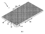
従来の布張りの家具に採用される中実芯体は人体表面との密着面積が大きく、人体にとって快適性ではなく、且つ陥没しやすく、特に周辺領域に非圧力型陥没が発生し、周辺領域が支持作用にならないという問題をもたらし、特に斬新な布張りの家具の芯体1を設計する。このような布張りの家具の芯体1は、マットレスまたはマットレスの一部として、あるいは枕または枕の一部として、寝具類に適用することができる。クッションまたはクッションの一部として、バックパッドまたはバックパッドの一部として、または肘掛けまたは肘掛けの一部として、ソファまたはシート製品に適用することもできる。図1~図4に示すように、このような布張りの家具の芯体1は弾性基体10を備え、弾性基体10に複数の弾性グリッドユニット11が形成される。各弾性グリッドユニット11は、弾性壁12によって囲まれている。2つの隣接する弾性グリッドユニット11の間には共通の辺を有し、線接続を形成し、又は共通の側壁を有し、平面接続を形成する。具体的には、任意の2つの隣接する弾性グリッドユニット11が対称的に設置され、2つの隣接する弾性グリッドユニット11を囲んでいる弾性壁12が対称軸上で互いに接続され、即ち共通の辺又は共通の側壁が対称軸上に位置する。図2及び図3の例に示すように、ここで、隣接する弾性グリッドユニット11-1と弾性グリッドユニット11-2との間に共通の側壁を有し、共通の側壁は対称軸15-1上に位置し、2つの弾性グリッドユニット11間の面接続を形成する。隣接する弾性グリッドユニット11-1と弾性グリッドユニット11との間に共通の辺を有し、共通の辺は対称軸15-2上に位置する。このような弾性グリッドユニット11の配列の接続方式は、弾性基体10が一定の柔軟性と良好な支持作用を有し、使用快適性が良好である。
The solid core body used in conventional upholstered furniture has a large contact area with the human body surface, which is not comfortable for the human body, and is easy to collapse, especially in the peripheral area, where non-pressure type depression occurs. brings about the problem of no support, specially designing the
具体的には、図1~図4に示すように、各弾性グリッドユニット11は弾性壁12の両端に形成された第1の端面13及び第2の端面24を有する。ここで、複数の弾性グリッドユニット11の第一端面13が共同で芯体の力受け面P1を形成し、複数の弾性グリッドユニット11の第2の端面24が同一平面上にあり、且つ芯体接続面P2を共同で形成する。ここで、芯体の力受け面P1は同一平面であってもよく、人間工学に基づいて設計された曲線を有するように設計してもよく、例えば芯体がバックパッドに適用される場合、対応する腰部の領域に突出するように設計してもよい。弾性グリッドユニット11は中空構造であり、且つ弾性壁12で囲まれるため、各弾性グリッドユニット11はいずれも比較的良好な引張強度を有し、限界伸び距離は元の長さの7倍以上に達することができる。2つの隣接する弾性グリッドユニット11は対称軸のみに線接続又は面接続を形成し、それにより弾性基体10全体が外力の作用でより大きな変形量を許容し、不可逆的変形が発生しにくい。且つ、不均一な外力の作用で、2つの隣接する弾性グリッドユニット11間の相互作用力が低く、ほぼ独立した支持形態を保持することができ、各弾性グリッドユニット11はいずれも一つの独立した支持力ユニットとすることができ、従って、ある領域が外力の作用で大幅に陥没する時に、隣接する弾性グリッドユニット11は明らかな陥没が発生せず、隣接する領域は依然として十分な支持力を提供する。図5は圧力と芯体高さの変化量との関係を示すグラフであり、ここでY1は従来の中実芯体を表し、Y2は本実施例が提供する芯体を表す。縦軸は圧力を表し、横軸は芯体の高さ変化量を表す。従来の中実芯体では、圧力が高くなるにつれて、芯体の高さの変化量が大きくなり、2者間で線形関係に近づく。本実施例が提供する芯体では、圧力が増加するにつれて、芯体の高さ変化が徐々にプラットフォーム区間に入り、このプラットフォーム区間において、芯体本体が陥没し続けるが、陥没深さが急激に変化せず、十分な支持力を維持しながら過大な反力が発生せず、外力が複数の弾性グリッドユニット11によって均衡に分散することができる。例えば人体における臀部曲線は凸状であり、芯体の高さ変化量がプラットフォーム区間に入ると、臀部と接触する芯体は小さい振幅で陥没して人体曲線を満たすことができ、同時に過大な反力を発生させずに身体に不快感を与えることがない。
Specifically, as shown in FIGS. 1-4, each
複数の弾性グリッドユニット11が同一平面上にある第2の端面からなる芯体接続面P2は主に他の補助材料と接続することに用いられる。芯体接続表面P2は接着剤、接着層等の形態及び他の材料によって接続されてもよく、又は縫合、リベット等の物理的接続形式及び他の材料接続を用いて接続されてもよい。
A core connection surface P2, which is the second end surface of the plurality of
弾性基体、特に弾性グリッドユニット11の構造的強度を高めるために、補助基体21がさらに形成されていることが好ましい。補助基体21は、芯体接続面P2に接続された面一になり完全な面を有する。
In order to increase the structural strength of the elastic base, especially the
この実施形態では、弾性壁12は、好ましくは熱可塑性エラストマー材料製であり、これにより、芯体がより快適になるように、可撓性と柔軟性と支持特性との間にバランスがとられる。当業者であれば理解できるように、弾性壁12が一定の弾性を有する高分子材料で製造された他のものであってもよい。複数のエラストマーユニットは熱可塑性プロセスによって一体的に成形することができ、また3D印刷の方式で一体成形することができる。可塑性エラストマー材料と部分的に溶融した接着剤、水溶性接着剤との直接結合ができないので、可塑性エラストマー材料に適合する補助基体21は、編み繊維、織られた繊維または不織布から作られることが特に好ましい。加工時に、熱可塑性エラストマー材料製の弾性基体とそれに適合する補助基体21とをホットスタンピング又は一体射出成形プロセスによって接続することができる。
In this embodiment, the
ホットスタンピング又は一体射出成形プロセスによって製造された補助基体21を有する弾性基体は、複数の標準寸法のユニットモジュールに分割することができる。またホットスタンピング又は一体射出成形プロセスによって標準寸法のユニットモジュールを製造することができ、且つ接合方式によって必要な使用寸法に達し、ここで弾性基体の長さ及び幅の寸法をさらに限定するものではない。
The elastic substrate with the
芯体がマットレス製品に適用される例として更に説明すると、マットレス製品に適用される場合、弾性芯体の芯体の力受け面と芯体の接続面P2はいずれも同一平面にあるように設計されることが好ましい。オプションの弾性グリッドユニット11の代替的な構造が、図6~14を参照して説明される。弾性グリッドユニット11は中空領域14を含み、中空領域14は弾性壁12の内側に形成される。各中空領域14の面積は1cm2~16cm2の範囲内に属し、中空領域14の面積が大きすぎて耐荷力の欠落が生じやすく、中空領域14の面積が小さすぎると弾性壁12が湾曲空間を有さず、外力の作用を受ける場合に、積層が発生し、弾性支持の効果を失う可能性がある。全体的に言えば、複数の中空領域14の面積の総和は弾性基体面積の70%から90%であり、高レベルの開孔率を実現し、芯体全体が優れた通気性を有する。
As an example in which the core is applied to a mattress product, the force-receiving surface of the elastic core and the connecting surface P2 of the core are both designed to be on the same plane when applied to a mattress product. preferably. Alternative constructions for the optional
弾性壁12の壁厚が1mm~10mmであり、壁厚が小さすぎると弾性壁12の支持力が不足し、壁厚が大きすぎると弾性壁12の弾性を低下させ、同時に、弾性壁12の壁厚がこの区間にあると加工プロセスの要件を満たすことができる。弾性壁12の高さは1cm~15cmであり、高さが低すぎて、十分な沈下深さを提供することができない。特にマットレスに適用される場合、弾性壁12の高さはこの区間内にあり、人体の重力を十分に分配することができる。マットレス全体の重量は、重量の観点から、より低いレベルに制御されることができる。
The wall thickness of the
図6及び図7に示すように、弾性グリッドユニット11の横断面は正6角形(図16に示す)に設計されてもよく、全体が結晶状に分布する。図8及び図9に示すように、弾性グリッドユニット11の横断面は三角形(図17に示される)に設計されてもよい。特に説明しなければならないのは、図10及び図11に示すように、三角形状に設計された弾性グリッドユニット11はさらに列状に配置されてもよく(図18に示す)、それにより複数列の弾性グリッドユニット11をさらに組み立てることができ、それにより長手方向に沿ってより良好な強度を実現し、異なるマットレス製品の具体的なニーズを満たす。図12~図14に示すように、弾性グリッドユニット11の横断面は円形(図19に示される)に設計されてもよく、弾性基体のエッジは図13に示すように保護壁を設置してよく、図12に示すように、弾性基体の辺に保護壁が設置されない。さらに、弾性グリッドユニット11の断面は、楕円形または他の形状の正多角形として設計されてもよい。
As shown in FIGS. 6 and 7, the cross-section of the
多くの応用場面において、弾性基体はさらに支持強度を向上させる必要がある。図15~図17に示すように、具体的には、芯体に支持基体30がさらに設置される。支持基体30はスポンジ、ラテックス、紡糸繊維、ホース又はバネによって支持される。支持基体30は1つに設置されてもよく、支持基体30は芯体接続面P2に接続されてもよく、支持基体と芯体接続面P2との間の接続は接着、縫合又はリベットでの物理的接続方式を用いてもよい。支持基体は補助基体21に接続されてもよく、図16に示すとおりである。製品の強度要件に応じて、支持基体はさらに複数(図17に30-1及び30-2に示される)を設計することができ、複数の支持基体が積層されて配置され、且つ最上層に位置する支持基体30-1が補助基体21に接続される。支持基体30-1と補助基体21との間の接続は接着、縫合又はリベットでの物理的接続方式を用いてもよい。
In many applications, the elastic substrate needs to have increased supporting strength. Specifically, as shown in FIGS. 15 to 17, a supporting
さらに、一つの芯体に複数の弾性基体が設置されてもよく、複数の弾性基体が均一に分布される。複数の弾性基体の間は第1の支持基体によって接続され、第1の支持基体は弾性基体の周囲に設置される。第1の支持基体表面は芯体接続面P2と同一平面にある。接続状態における第1の支持基体及び弾性基体は補助基体21に接続されてもよく、第2の支持基体に接続されてもよい。接続は、同様に接着、縫合又はリベットでの物理的接続方式を使用することができる。第1の支持基体及び第2の支持基体はいずれもスポンジ、ラテックス、紡糸繊維、ホース又はバネで構成されてもよい。
Furthermore, a plurality of elastic substrates may be installed on one core, and the plurality of elastic substrates are evenly distributed. The plurality of elastic bases are connected by a first support base, and the first support base is installed around the elastic bases. The first supporting substrate surface is flush with the core connection surface P2. The first supporting base and the elastic base in the connected state may be connected to the
本考案の別の態様は、布張りの家具を提供する。布張りの家具に布張りの家具の芯体が設置される。布張りの家具の芯体の具体的な構造は上記実施例及び明細書図面の詳細な説明を参照し、ここでは説明を省略し、上記布張りの家具の芯体が設置される布張りの家具は同様の技術的効果を実現することができる。布張りの家具はマットレスであることが好ましい。 Another aspect of the invention provides upholstered furniture. An upholstered furniture core is placed on the upholstered furniture. For the specific structure of the upholstered furniture core, refer to the detailed description of the above embodiments and specification drawings, and omit the description here. Furniture can achieve similar technical effects. The upholstered furniture is preferably a mattress.
以上の実施例は、本考案の技術的解決手段を説明するためのものに過ぎず、それを制限するものではない。上記実施例を参照して本考案を詳細に説明したが、当業者であれば、依然として前述の実施例に記載の解決手段を変更することができ、又はその一部の特徴を同等に置換することができる。これらの修正又は置換は、対応する技術的解決手段の本質を本考案が保護を求める技術的解決手段の要旨及び範囲から逸脱させることはない。 The above examples are only for describing the technical solutions of the present invention, but not for limiting it. Although the present invention has been described in detail with reference to the above embodiments, those skilled in the art can still modify the solutions described in the above embodiments, or equivalently replace some features thereof. be able to. These modifications or replacements do not make the essence of the corresponding technical solution depart from the gist and scope of the technical solution for which this invention seeks protection.
Claims (10)
複数の弾性グリッドユニットが形成される弾性基体を備え、
ここで、各前記弾性グリッドユニットは弾性壁に囲まれ、任意の2つの隣接する前記弾性グリッドユニットは対称に配置され、且つ前記2つの隣接する弾性グリッドユニットを囲んでいる前記弾性壁は対称軸上で互いに接続されていることを特徴とする布張りの家具の芯体。 A core of upholstered furniture,
comprising an elastic base on which a plurality of elastic grid units are formed;
wherein each said elastic grid unit is surrounded by an elastic wall, any two adjacent said elastic grid units are arranged symmetrically, and said elastic walls surrounding said two adjacent elastic grid units have an axis of symmetry Core bodies of upholstered furniture, characterized in that they are connected to each other on top.
ここで、前記弾性壁は熱可塑性エラストマー材料製であり、前記補助基体は編み繊維、紡織繊維、または不織布で構成され、前記弾性基体と前記補助基体は、ホットブランキングまたは一体型射出成形によって接続されていることを特徴とする請求項2に記載の布張りの家具の芯体。 further comprising an auxiliary base connected to the connecting surface of the core of the elastic base;
wherein said elastic wall is made of thermoplastic elastomer material, said auxiliary substrate is made of knitted fiber, textile fiber or non-woven fabric, said elastic substrate and said auxiliary substrate are connected by hot blanking or integral injection molding. 3. A core body for upholstered furniture according to claim 2, characterized in that it is .
前記弾性基体の周りに配置され、表面が前記弾性基体の芯体接続面と同一平面である第1の支持基体と、
それぞれ前記弾性基体の芯体接続面と前記第1の支持基体表面に接続されている、少なくとも1つの第2の支持基体と、をさらに備え、
前記第1の支持基体は、スポンジ、ラテックス、紡糸繊維、ホース、又はバネで構成され、前記第2の支持基体は、スポンジ、ラテックス、紡糸繊維、ホース、又はバネで構成されることを特徴とする請求項2に記載の布張りの家具の芯体。 said upholstered furniture core comprising a plurality of uniformly distributed elastic substrates;
a first supporting base disposed around the elastic base and having a surface flush with the core connecting surface of the elastic base;
at least one second support base connected to the core connection surface of the elastic base and the surface of the first support base, respectively;
The first supporting substrate is composed of sponge, latex, spun fiber, hose, or spring, and the second supporting substrate is composed of sponge, latex, spun fiber, hose, or spring. An upholstered furniture core according to claim 2.
各前記中空領域の面積は、1cm2~16cm2であり、且つ複数の前記中空領域の面積の総和は、前記弾性基体の面積の70%~90%であり、
前記弾性壁の肉厚は、1mm~10mmであり、前記弾性壁の高さは、1cm~15cmであり、前記弾性グリッドユニットの断面は、矩形、円形、楕円形、三角形または正方形の多角形であることを特徴とする請求項1から7のいずれか一項に記載の布張りの家具の芯体。 The elastic grid unit further comprises a hollow area formed inside the elastic wall,
The area of each hollow region is 1 cm 2 to 16 cm 2 , and the total area of the plurality of hollow regions is 70% to 90% of the area of the elastic base,
The thickness of the elastic wall is 1 mm to 10 mm, the height of the elastic wall is 1 cm to 15 cm, and the cross section of the elastic grid unit is rectangular, circular, oval, triangular or square polygonal. 8. A core of upholstered furniture according to any one of claims 1 to 7, characterized in that:
Applications Claiming Priority (3)
| Application Number | Priority Date | Filing Date | Title |
|---|---|---|---|
| CN202020477804.1 | 2020-04-03 | ||
| CN202020477804.1U CN211984695U (en) | 2020-04-03 | 2020-04-03 | Soft furniture core and soft furniture |
| PCT/CN2020/086450 WO2021196318A1 (en) | 2020-04-03 | 2020-04-23 | Upholstered furniture core and upholstered furniture |
Publications (1)
| Publication Number | Publication Date |
|---|---|
| JP3241161U true JP3241161U (en) | 2023-03-09 |
Family
ID=73404205
Family Applications (1)
| Application Number | Title | Priority Date | Filing Date |
|---|---|---|---|
| JP2021600033U Active JP3241161U (en) | 2020-04-03 | 2020-04-23 | Upholstered furniture cores and upholstered furniture |
Country Status (6)
| Country | Link |
|---|---|
| JP (1) | JP3241161U (en) |
| KR (1) | KR200497508Y1 (en) |
| CN (1) | CN211984695U (en) |
| AU (1) | AU2021100726A4 (en) |
| DE (1) | DE212020000283U1 (en) |
| WO (1) | WO2021196318A1 (en) |
Family Cites Families (5)
| Publication number | Priority date | Publication date | Assignee | Title |
|---|---|---|---|---|
| EP2248446A1 (en) * | 2009-05-08 | 2010-11-10 | Ecolatex S.r.l. | Method for the manufacturing of mattresses or similar, especially made of latex, by means of the reversible combination of component modules, and mattresses or similar thus obtained |
| CN202104587U (en) * | 2011-06-22 | 2012-01-11 | 富声国际股份有限公司 | Shock-absorbing and pressure-dispersing structure |
| CN203709660U (en) * | 2014-01-15 | 2014-07-16 | 梁大业 | Novel space memory foam mattress |
| JP2016135226A (en) * | 2015-06-16 | 2016-07-28 | 株式会社パシフィックウエーブ | Flame retardant cubic lattice shape cushion |
| CN209090494U (en) * | 2017-11-28 | 2019-07-12 | 宏达益企业有限公司 | Multifunctional support pad |
-
2020
- 2020-04-03 CN CN202020477804.1U patent/CN211984695U/en active Active
- 2020-04-23 JP JP2021600033U patent/JP3241161U/en active Active
- 2020-04-23 DE DE212020000283.5U patent/DE212020000283U1/en active Active
- 2020-04-23 KR KR2020217000079U patent/KR200497508Y1/en active Active
- 2020-04-23 WO PCT/CN2020/086450 patent/WO2021196318A1/en active Application Filing
-
2021
- 2021-02-05 AU AU2021100726A patent/AU2021100726A4/en active Active
Also Published As
| Publication number | Publication date |
|---|---|
| AU2021100726A4 (en) | 2021-04-22 |
| KR200497508Y1 (en) | 2023-11-29 |
| CN211984695U (en) | 2020-11-24 |
| DE212020000283U1 (en) | 2020-12-09 |
| KR20210002769U (en) | 2021-12-10 |
| WO2021196318A1 (en) | 2021-10-07 |
Similar Documents
| Publication | Publication Date | Title |
|---|---|---|
| US10743675B2 (en) | Pillow | |
| US11528997B2 (en) | Pocket spring unit | |
| EP4385366A1 (en) | Elastic module balancing cushion, elastic cushion and furniture | |
| JP3241161U (en) | Upholstered furniture cores and upholstered furniture | |
| EP1602303A2 (en) | Springing device particulary for mattresses | |
| KR20200093789A (en) | Cushion made of cushion plates | |
| CN202820472U (en) | Upholstery | |
| CN201938878U (en) | Cushion | |
| CN108078272A (en) | Seat cushion and its support construction | |
| CN214711681U (en) | Resin ball mattress | |
| CN212307379U (en) | Palm fiber cushion with good comfort | |
| US20230093997A1 (en) | Mattress having three-dimensional elastic structure | |
| CN210661164U (en) | A resin ball member and a mattress using the resin ball member | |
| CN210672788U (en) | Supporting device | |
| CN213487998U (en) | Air-permeable anti-deformation mat | |
| KR101512801B1 (en) | Cushion mat | |
| CN213786440U (en) | Supporting pad that subregion multiple spot supported | |
| CN217039487U (en) | Mattress capable of dispersing pressure | |
| KR102668348B1 (en) | Active body pressure dispersion-typed air cell mattress | |
| CN209750513U (en) | Intelligent spring | |
| CN221179949U (en) | Spliced independent bagged spring sponge mattress | |
| KR102356586B1 (en) | Mattress with differentiated rigidity | |
| CN221105357U (en) | Mattress structure with good supporting effect | |
| CN213308615U (en) | Novel mattress with optional hardness | |
| US20230124911A1 (en) | Pillow |
Legal Events
| Date | Code | Title | Description |
|---|---|---|---|
| R150 | Certificate of patent or registration of utility model |
Ref document number: 3241161 Country of ref document: JP Free format text: JAPANESE INTERMEDIATE CODE: R150 |
|
| A623 | Registrability report |
Free format text: JAPANESE INTERMEDIATE CODE: A623 Effective date: 20250306 |