JP3194494U - Folding chassis - Google Patents
Folding chassis Download PDFInfo
- Publication number
- JP3194494U JP3194494U JP2014004436U JP2014004436U JP3194494U JP 3194494 U JP3194494 U JP 3194494U JP 2014004436 U JP2014004436 U JP 2014004436U JP 2014004436 U JP2014004436 U JP 2014004436U JP 3194494 U JP3194494 U JP 3194494U
- Authority
- JP
- Japan
- Prior art keywords
- chassis
- locking
- fixing member
- hole
- pivot
- Prior art date
- Legal status (The legal status is an assumption and is not a legal conclusion. Google has not performed a legal analysis and makes no representation as to the accuracy of the status listed.)
- Expired - Fee Related
Links
- 230000008878 coupling Effects 0.000 claims description 12
- 238000010168 coupling process Methods 0.000 claims description 12
- 238000005859 coupling reaction Methods 0.000 claims description 12
- 230000002093 peripheral effect Effects 0.000 claims description 12
- 230000035515 penetration Effects 0.000 claims description 2
- 238000010586 diagram Methods 0.000 description 18
- 238000000354 decomposition reaction Methods 0.000 description 6
- 230000006835 compression Effects 0.000 description 2
- 238000007906 compression Methods 0.000 description 2
- 230000000694 effects Effects 0.000 description 2
- 230000005489 elastic deformation Effects 0.000 description 1
- 238000000034 method Methods 0.000 description 1
- 230000000630 rising effect Effects 0.000 description 1
- 239000007787 solid Substances 0.000 description 1
Images


Landscapes
- Pivots And Pivotal Connections (AREA)
Abstract
【課題】折畳み式車台に使用され、安全性を高める折畳みの構造を提供する。【解決手段】第一車台1には一個の第一枢接孔15と一個の導引孔16が設けられる。第二車台2には一個の第二枢接孔221と一個の貫穿孔222が設けられ、第二車台2と第一車台1は互いに嵌接される。位置決めモジュール3には二個の位置決め部材31、一個の第一固定部材32、一個の第二固定部材33と一個の弾力位置決めユニット34が含まれ、各位置決め部材31は第二車台2の外表面と第一車台1の内表面に当接し、かつ第二枢接孔221と同軸し、第一固定部材32は第一車台1のその内の一方から第一枢接孔15、第二枢接孔221と二個の位置決め部材31を貫穿し、さらに第一車台1のもう一方に設けられる第二固定部材33まで結合され、弾力位置決めユニット34は貫穿孔222を貫穿し、かつ弾力位置決めユニット34の両端は導引孔16に位置合わせて当接する。【選択図】図2The present invention provides a folding structure that is used in a folding chassis and enhances safety. The first chassis is provided with one first pivot hole and one guide hole. The second chassis 2 is provided with one second pivot hole 221 and one through hole 222, and the second chassis 2 and the first chassis 1 are fitted together. The positioning module 3 includes two positioning members 31, one first fixing member 32, one second fixing member 33 and one elastic positioning unit 34, and each positioning member 31 is an outer surface of the second chassis 2. The first fixing member 32 from one of the first chassis 1 to the first pivot hole 15 and the second pivot. The hole 221 and the two positioning members 31 are penetrated, and further coupled to the second fixing member 33 provided on the other side of the first chassis 1. The elastic positioning unit 34 penetrates the through hole 222 and the elastic positioning unit 34. Both ends of the contact are in contact with the guide hole 16 in alignment. [Selection] Figure 2
Description
本考案は、車台に関するもので、特に、折畳み式車台に係るものである。 The present invention relates to a chassis, and particularly relates to a folding chassis.
図14および15は従来の折畳み式のキックスクーターを示す図で、図14は従来の折畳み式位置決め構造を有するキックスクーターの平面構造の説明図であり、図15は従来の折畳み式位置決め構造の断面構造の説明図である。図14、15を参照すると、従来の折畳み位置決め構造9にはキックスクーター取っ手部材Aに結合された一個の方形管91、キックスクーター本体Bに固設された一個の固定座92および一個の位置決めユニット93が含まれる。
14 and 15 are views showing a conventional folding kick scooter, FIG. 14 is an explanatory view of a planar structure of a kick scooter having a conventional folding positioning structure, and FIG. 15 is a cross-sectional view of the conventional folding positioning structure. It is explanatory drawing of a structure. Referring to FIGS. 14 and 15, the conventional
固定座92は二個の立板921により構成され、各立板921には一個の枢接孔922と一個の円弧形軌道孔923が設けられ、かつ二個の立板921の枢接孔922と円弧形軌道孔923は互いに対応し、方形管91は二個の立板921の間に枢接され、さらに位置決めユニット93により固定座92に貫穿して方形管91と結合して固定する。
The fixed
その内、各円弧形軌道孔923の両端にはそれぞれ一個の凹入部924が設けられ、位置決めユニット93は一個の急速離脱ボルト931、一個のナット932、一個のばね933および二個の位置決め栓934により構成される。急速離脱ボルト931は固定座92の一辺から二個の位置決め栓934とばね933を貫穿し、さらにナット932をもって固定座92のもう一辺から螺接して組立を完成する。急速離脱ボルト932には一個の枢転自在のスパナ935が連接され、かつ二個の位置決め栓934にはそれぞれ一個のフランジ936が設けられる。
Among them, one
これにより、スパナ935を作動させることにより、スパナ935を利用して二個の位置決め栓934を張るように引っ張ったり、または緩むように放したりすることにより、二個の位置決め栓934は方形管91の立ち上がりまたは折畳みに従って二個の円弧形軌道孔923の間において滑動し、さらに二個の位置決め栓934のフランジ936により二個の円弧形軌道孔923の両端の凹入部924に圧し入れられて固定の形態に形成される。このような従来の折畳み位置決め構造9の一つの実施例として中華民国公告第506383号「キックスクーター折畳み位置決め構造」に開示されている(特許文献1参照)。
Accordingly, by operating the
しかしながら、このような従来の折畳み位置決め構造9は、スパナ935を利用して二個の位置決め栓934を張るように引っ張ったり、または緩むように放したりすることにより、方形管91と固定座92の間を相対的な枢転状態または固定するように結合して相対的な枢転ができないように制御するものである。しかし、スパナ935はキックスクーターの外側に露出し、かつスパナ935の末端にはいかなる引っ掛け防止の設計がないため、実際に使用している時に不意の衝突、またはその他の物体によって引っ掛けられたりしてスパナ935を作動させてしまうという状況がしばしば発生され、そのため、折畳み位置決め構造9を用いたキックスクーターの使用はその安全性が依然として憂慮されている。特に、従来の折畳み位置決め構造9を幼児が騎乗する二輪車等(例えば幼児用自転車、ストライダー等)に使用した時、幼児は好奇心または面白いからといって勝手にスパナ935を作動することにより、事故が起きるという問題点があった。
However, such a conventional
本考案はこのような問題点に鑑みて考案されたものであって、その第一の目的は、使用時において衝突したり、物体に引っ掛けたりすることにより、車台が枢転自在の折畳み状態になることがないように構成し、それにより、使用上の安全性を高めることができる折畳み式車台を提供することにある。 The present invention has been devised in view of such problems, and its first purpose is to make the chassis into a folding state in which it can be pivoted by colliding in use or being caught on an object. An object of the present invention is to provide a foldable chassis that can be configured so as to prevent accidents and thereby improve safety in use.
本考案の第二の目的は、幼児の騎乗用の二輪車等に使用しても、幼児自らが車台が枢転自在の折畳み状態にさせてしまうのを防止することにより、不要な事故が発生するのを減らすことができる折畳み式車台を提供することにある。 The second purpose of the present invention is that even if it is used for a motorcycle for riding an infant, an unnecessary accident occurs by preventing the infant from causing the chassis to fold in a pivotable manner. An object of the present invention is to provide a folding chassis that can reduce the amount of the vehicle.
上記目的を達成するために、本考案による折畳み式車台は、一個の第一車台、一個の第二車台および一個の位置決めモジュールが含まれる。上記第一車台の前端には一個の第一枢接孔と一個の導引孔が設けられ、上記第一枢接孔と導引孔は全て上記第一車台の左、右両側まで貫穿される。上記第二車台の後端には一個の第二枢接孔と一個の貫穿孔が設けられ、上記第二枢接孔と貫穿孔は全て上記第二車台の左、右両側まで貫穿される。上記第二車台の後端と上記第一車台の前端は互いに嵌接され、上記第二枢接孔と上記第一枢接孔は互いに位置合わせされ、上記貫穿孔と上記導引孔は互いに位置合わせされる。上記位置決めモジュールには二個の位置決め部材、一個の第一固定部材、一個の第二固定部材および一個の弾力位置決めユニットが含まれる。上記各位置決め部材は上記第二車台の外表面と上記第一車台の内表面に当接する。上記各位置決め部材と上記第二枢接孔は同軸で、上記第一固定部材は上記第一車台のその内の一方から上記第一枢接孔、上記第二枢接孔および上記二個の位置決め部材を貫穿し、かつ上記第一車台のもう一方に設けられる上記第二固定部材まで結合される。上記弾力位置決めユニットは上記貫穿孔を貫穿し、上記弾力位置決めユニットの両端は上記導引孔に位置合わせして当接される。上記導引孔には互いに連通する一個の小径部と二個の大径部が含まれる。上記各大径部の径幅は上記小径部の径幅より大きく、上記二個の大径部は上記小径部の両端に設けられる。上記弾力位置決めユニットには一個の弾性部材と二個の凸部が含まれる。上記二個の凸部はそれぞれ上記弾性部材の軸方向の両端に連接され、上記各凸部の環状周壁面には一個の肩部が設けられる。上記凸部の自由端から上記肩部の間は円弧形として一個の係止部が形成される。上記係止部が上記肩部と連接する部位の径幅は上記導引孔の大径部の径幅より小さく、かつ上記導引孔のその他の部位の径幅より大きく、さらに上記各凸部の係止部から上記導引孔の大径部の中に貫穿される。上記各凸部の肩部は上記第一車台の内表面に当接し、または上記各凸部の係止部は上記第一車台の内表面に当接し、さらに上記導引孔の小径部の中に貫穿される。上記弾力位置決めユニットには他に一個の軸管が設けられる。上記軸管は上記第二車台の貫穿孔を貫穿し、上記軸管は上記第二車台の外表面から突き出るように延伸され、上記第一車台の内表面と接触しないように形成される。上記弾性部材は上記軸管の中に収容され、上記二個の凸部は上記弾性部材の端部と連接して上記軸管の中に収容される。上記各位置決め部材には一個の内環と一個の外環が含まれる。上記内環は上記外環の中に設けられ、かつ上記外環と同軸で、上記内環と上記外環の一個の端面は一個の当接面によって互いに連接しする。上記内環のもう一個の端面は上記外環のもう一個の端面から突き出るように延伸される。上記各位置決め部材は上記内環で上記外環の端面から突き出て上記第二枢接孔に嵌入され、上記外環の端面は上記第二車台の外表面に当接し、上記当接面は上記第一車台の内表面に当接する。上記第一固定部材には一個のヘッドと一個の桿体が含まれる。上記第一固定部材のヘッドは上記桿体の一端に連接され、上記桿体のもう一端には内ねじが設けられる。上記第二固定部材には一個のヘッドと一個の外ねじ部が含まれる。上記第二固定部材のヘッドは上記外ねじ部の一端に連接され、上記第二固定部材の外ねじ部と上記第一固定部材の内ねじは互いに螺合する。上記第二車台には一個の套管部と一個の枢接部が含まれる。上記枢接部の前端は上記套管部の外周面に結合され、上記第二枢接孔と貫穿孔は上記枢接部の後端に設けられ、さらに上記枢接部の左、右両側まで貫穿される。上記第一車台の上部に一個のサドル結合部が設けられ、上記第一車台の前端に一個の嵌接口が設けられる。上記第一車台の第一枢接孔と導引孔は相対的に上記嵌接口に近接し、かつ上記サドル結合部から遠く離れるように形成される。上記第二車台は上記枢接部の後端から上記第一車台の嵌接口に嵌入され、上記第一車台の底部には内部まで連接する一個の開口が設けられる。 To achieve the above object, a folding chassis according to the present invention includes one first chassis, one second chassis, and one positioning module. The front end of the first chassis is provided with a first pivot hole and a guide hole, and the first pivot hole and the guide hole are all penetrated to the left and right sides of the first chassis. . A rear end of the second chassis is provided with a second pivot hole and a through hole. The second pivot hole and the through hole are all penetrated to the left and right sides of the second chassis. The rear end of the second chassis and the front end of the first chassis are fitted into each other, the second pivot hole and the first pivot hole are aligned with each other, and the through hole and the guide hole are positioned with respect to each other. To be combined. The positioning module includes two positioning members, one first fixing member, one second fixing member, and one elastic positioning unit. Each positioning member contacts the outer surface of the second chassis and the inner surface of the first chassis. The positioning members and the second pivot holes are coaxial, and the first fixing member is positioned from one of the first chassis to the first pivot hole, the second pivot hole, and the two positioning holes. A member is penetrated and connected to the second fixing member provided on the other side of the first chassis. The elastic positioning unit penetrates the through hole, and both ends of the elastic positioning unit are in contact with the guide hole in alignment. The guide hole includes one small diameter portion and two large diameter portions communicating with each other. The diameter width of each large diameter portion is larger than the diameter width of the small diameter portion, and the two large diameter portions are provided at both ends of the small diameter portion. The elastic positioning unit includes one elastic member and two convex portions. The two convex portions are respectively connected to both ends of the elastic member in the axial direction, and one shoulder portion is provided on the annular peripheral wall surface of each convex portion. One locking portion is formed as an arc shape between the free end of the convex portion and the shoulder portion. The diameter width of the portion where the locking portion is connected to the shoulder portion is smaller than the diameter width of the large diameter portion of the guide hole and larger than the diameter width of the other portion of the guide hole, and each convex portion. Is penetrated into the large diameter portion of the guide hole. The shoulder of each convex part abuts on the inner surface of the first chassis, or the engaging part of each convex part abuts on the inner surface of the first chassis, and further in the small diameter part of the guide hole. It is penetrated by. In addition, the elastic positioning unit is provided with one shaft tube. The shaft tube penetrates the through hole of the second chassis, and the shaft tube extends so as to protrude from the outer surface of the second chassis, and is formed so as not to contact the inner surface of the first chassis. The elastic member is housed in the shaft tube, and the two convex portions are housed in the shaft tube so as to be connected to end portions of the elastic member. Each positioning member includes one inner ring and one outer ring. The inner ring is provided in the outer ring and is coaxial with the outer ring, and one end face of the inner ring and the outer ring is connected to each other by a single contact surface. The other end face of the inner ring is extended so as to protrude from the other end face of the outer ring. Each positioning member protrudes from the end face of the outer ring at the inner ring and is fitted into the second pivot hole. The end face of the outer ring contacts the outer surface of the second chassis, and the contact surface is It contacts the inner surface of the first chassis. The first fixing member includes one head and one housing. The head of the first fixing member is connected to one end of the casing, and an inner screw is provided at the other end of the casing. The second fixing member includes one head and one external thread portion. The head of the second fixing member is connected to one end of the outer screw portion, and the outer screw portion of the second fixing member and the inner screw of the first fixing member are screwed together. The second chassis includes one cannula and one pivot. The front end of the pivot portion is coupled to the outer peripheral surface of the sleeve portion, the second pivot hole and the through hole are provided at the rear end of the pivot portion, and further to both the left and right sides of the pivot portion. It is penetrated. One saddle coupling portion is provided at the upper portion of the first chassis, and one fitting contact is provided at the front end of the first chassis. The first pivot hole and the guide hole of the first chassis are formed so as to be relatively close to the fitting contact and far away from the saddle coupling portion. The second chassis is fitted into the fitting opening of the first chassis from the rear end of the pivot part, and a single opening is provided at the bottom of the first chassis.
また、本考案による折畳み式車台は次のように構成することもできる。二個の第三車台および二個の固定モジュールを含み、上記第一車台の後端の両側にはそれぞれ一個の延伸部が設けられ、上記各延伸部には一個の第三枢接孔と一個の係止貫穿孔が設けられ、上記各第三車台の一端には一個の第四枢接孔と一個の開孔が設けられる。上記二個の第三車台はそれぞれ対応する延伸部に結合される。上記第四枢接孔と上記第三枢接孔は互いに位置合わせされ、上記開孔と上記係止貫穿孔は互いに位置合わせされる。上記各固定モジュールには一個の第三固定部材、一個の第四固定部材および一個の弾性位置決めユニットが含まれる。上記第三固定部材は上記第一車台の対応する延伸部の内側から上記第三枢接孔と上記第三車台の第四枢接孔を貫穿し、さらに上記第四固定部材が上記延伸部の外側から螺接して結合するのに用いられる。上記弾性位置決めユニットは対応する第三車台の内に設けられる。上記弾性位置決めユニットの一端は上記第三車台の開孔から突き出るように形成され、さらに対応する延伸部の係止貫穿孔に嵌入して係止するように形成される。上記各固定モジュールには他に一個の係止部材と一個の係止フックが含まれる。上記係止部材は対応する第三車台の外側に設けられる。上記係止部材には一個の斜面と一個の係止面が含まれる。上記係止部材の斜面は上記係止部材の上部から上記第三車台の外表面に向って斜め方向に延伸し、上記係止部材の係止面は上記係止部材の上部から上記第三車台の外表面に向って垂直に延伸する。上記第一車台の上部に一個のサドル結合部が設けられ、上記サドル結合部には一個のサドルが結合される。上記係止フックは上記サドルの内表面の側端縁に設けられる。上記係止フックには一個の斜面と一個の係止面が含まれ、上記係止フックの斜面の一個の端縁は上記サドルの内表面に連接され、上記係止フックの係止面の一個の端縁は上記サドルの外表面に連接される。上記係止フックの係止面は上記係止部材の係止面に当接する。上記弾性位置決めユニットには一個の弾性部材と一個の凸部が含まれる。上記弾性位置決めユニットの凸部は上記弾性位置決めユニットの弾性部材の軸方向の一端に連接され、上記弾性位置決めユニットの凸部の環状周壁面には一個の肩部が設けられる。上記弾性位置決めユニットの凸部の自由端から上記肩部の間は円弧形として一個の係止部が形成され、上記弾性位置決めユニットの凸部は上記肩部から上記第三車台の内周壁に当接し、さらに上記係止部により上記第三車台の開孔から突き出るように形成される。上記弾性位置決めユニットには他に一個の管座が設けられる。上記管座は対応する第三車台の内に設けられる。上記弾性位置決めユニットの弾性部材は上記管座の中に収容され、上記弾性位置決めユニットの凸部が上記弾性位置決めユニットに連接する弾性部材の端部は上記管座の中に収容される。上記第三固定部材には一個のヘッドと一個の桿体が含まれる。上記第三固定部材のヘッドは上記第三固定部材の桿体の一端に連接され、上記第三固定部材の桿体のもう一端には内ねじが設けられる。上記第四固定部材には一個のヘッドと一個の外ねじ部が含まれる。上記第四固定部材のヘッドは上記第四固定部材の外ねじ部の一端に連接され、上記第四固定部材の外ねじ部と上記第三固定部材の内ねじは互いに螺合する。 The folding chassis according to the present invention can also be configured as follows. Including two third chassis and two fixing modules, each of which is provided with one extending portion on each side of the rear end of the first chassis, and each extending portion has one third pivot hole and one The third through-holes are provided with one fourth pivot hole and one opening at one end of each third chassis. The two third chassis are respectively coupled to the corresponding extending portions. The fourth pivot hole and the third pivot hole are aligned with each other, and the opening and the locking through hole are aligned with each other. Each fixing module includes one third fixing member, one fourth fixing member, and one elastic positioning unit. The third fixing member penetrates the third pivot hole and the fourth pivot hole of the third chassis from the inside of the corresponding extension part of the first chassis, and the fourth fixing member further extends to the extension part. Used to join by screwing from the outside. The elastic positioning unit is provided in a corresponding third chassis. One end of the elastic positioning unit is formed so as to protrude from the opening of the third chassis, and is further formed so as to be fitted and locked in a locking through hole of a corresponding extending portion. Each of the fixing modules further includes one locking member and one locking hook. The locking member is provided outside the corresponding third chassis. The locking member includes one slope and one locking surface. The slope of the locking member extends obliquely from the top of the locking member toward the outer surface of the third chassis, and the locking surface of the locking member extends from the top of the locking member to the third chassis. Stretching perpendicularly to the outer surface. One saddle coupling portion is provided on the upper portion of the first chassis, and one saddle is coupled to the saddle coupling portion. The locking hook is provided on a side edge of the inner surface of the saddle. The locking hook includes one slope and one locking surface, and one edge of the locking hook slope is connected to the inner surface of the saddle, and one locking surface of the locking hook is provided. Are connected to the outer surface of the saddle. The locking surface of the locking hook contacts the locking surface of the locking member. The elastic positioning unit includes one elastic member and one convex portion. The convex portion of the elastic positioning unit is connected to one end of the elastic member of the elastic positioning unit in the axial direction, and one shoulder is provided on the annular peripheral wall surface of the convex portion of the elastic positioning unit. Between the free end of the convex portion of the elastic positioning unit and the shoulder portion, a single locking portion is formed as an arc shape, and the convex portion of the elastic positioning unit extends from the shoulder portion to the inner peripheral wall of the third chassis. Further, it is formed so as to protrude from the opening of the third chassis by the locking portion. In addition, one tube seat is provided in the elastic positioning unit. The tube seat is provided in a corresponding third chassis. The elastic member of the elastic positioning unit is accommodated in the tube seat, and the end of the elastic member where the convex portion of the elastic positioning unit is connected to the elastic positioning unit is accommodated in the tube seat. The third fixing member includes one head and one housing. The head of the third fixing member is connected to one end of the casing of the third fixing member, and an internal screw is provided at the other end of the casing of the third fixing member. The fourth fixing member includes one head and one external thread portion. The head of the fourth fixing member is connected to one end of the outer screw portion of the fourth fixing member, and the outer screw portion of the fourth fixing member and the inner screw of the third fixing member are screwed together.
本考案の折畳み式車台によれば、使用時において衝突したり、物体に引っ掛けたりすることによって車台が枢転自在の折畳み状態になることがないため、使用上の安全性を高めることができるという利点がある。 According to the folding type chassis of the present invention, it is possible to increase the safety in use because the chassis does not enter a pivotable folding state by colliding in use or being hooked on an object. There are advantages.
本考案の折畳み式車台によれば、幼児の騎乗用の二輪車等に使用されても、幼児自らが車台を枢転自在の折畳み状態にするのを防止することができるため、不要な事故が発生するのを減らすことができるという利点がある。 According to the folding chassis of the present invention, even if it is used for a motorcycle for riding an infant, the infant can prevent the infant from turning the chassis into a folding state so that an unnecessary accident occurs. There is an advantage that can be reduced.
本考案の実施の形態について、以下、図面を参照して説明する。 Embodiments of the present invention will be described below with reference to the drawings.
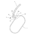
図1は本考案の実施例1による折畳み式車台の立体構造の説明図である。折畳み式車台には大別して一個の第一車台1、一個の第二車台2および一個の位置決めモジュール3が含まれ、さらに位置決めモジュール3により第一車台1と第二車台2が相対的に枢転できるか否かを制御することができる。
FIG. 1 is an explanatory view of a three-dimensional structure of a folding chassis according to the first embodiment of the present invention. The folding chassis is roughly divided into one
本考案の折畳み式車台はいかなる構造形態およびサイズからなることができる。構造形態から言えば、本折畳み式車台は自転車、キックスクーター、ストライダー(商標:キッズ用ペタルなし自転車)等の異なる車種の車体の基台からなることができる。さらに、本折畳み式車台は二輪車体の基台、三輪車体の基台、またはその他の構造形態を有する車体の基台からなることができる。一方、サイズから言えば、本折畳み式車台は一般的に大人が使用する車体の基台としても、幼児が使用する小型車体の基台としても使用することができる。このように、本考案の折畳み式車台は使用の需要性に応じて調整することができることは、本考案に所属する技術分野で通常の知識を有するものにとって容易に理解できるものであり、本考案においてはそれについての制限を設けるものではないが、本考案の実施例1は幼児用の二輪ストライダーの折畳み式車台を例に挙げて説明を行なう。 The folding chassis of the present invention can be of any structural form and size. In terms of structure, the folding chassis can be composed of a base of a vehicle body of a different vehicle type such as a bicycle, kick scooter, strider (trademark: bicycle without petal for kids). Further, the foldable chassis can be a two-wheel vehicle base, a three-wheel vehicle base, or a vehicle body base having another structure. On the other hand, in terms of size, the foldable chassis can be used as a base for a car body generally used by an adult or as a base for a small car body used by an infant. Thus, the fact that the folding chassis of the present invention can be adjusted according to the demand for use can be easily understood by those having ordinary knowledge in the technical field belonging to the present invention. However, the first embodiment of the present invention will be described by taking a folding chassis of a two-wheeled strider for infants as an example.
図2は本考案の実施例1の立体分解構造の説明図である。図1、2を参照すると、第一車台1の上部には一個のサドル結合部11が設けられ、一個のサドルSを設置するのに用いられる。第一車台1の底部には一個の内部まで連通する開口12が設けられる。第一車台1の後端には一個の車輪枢接部13が設けられ、一個の後輪Rを枢接するのに用いられ、上記第一車台1の前端には一個の嵌接口14が設けられ、第二車台2と嵌合するのに用いられる。第一車台1の前端にはその他に一個の第一枢接孔15と一個の導引孔16が設けられる。第一枢接孔15と導引孔16は相対的に嵌接口14に近接し、そして相対的にサドル結合部11から遠く離れるように形成され、かつ第一枢接孔15と導引孔16は全て第一車台1の左、右両側まで貫穿する。
FIG. 2 is an explanatory view of the three-dimensional decomposition structure according to the first embodiment of the present invention. Referring to FIGS. 1 and 2, a single
図3は本考案の実施例1の局部の立体分解構造の説明図である。図3を合わせて参照すると、導引孔16には互いに連通する一個の小径部161と二個の大径部162が含まれる。導引孔16の小径部161は約四分の一円の円弧形を有する。各大径部162の径幅は小径部161の径幅より大きく、二個の大径部162は小径部161の両端に設けられる。
FIG. 3 is an explanatory diagram of a local three-dimensional decomposition structure according to the first embodiment of the present invention. Referring also to FIG. 3, the
再び図2、3を参照すると、第二車台2には一個の套管部21と一個の枢接部22が含まれる。套管部21は一個の軸桿Pが貫穿するのに用いられ、軸桿Pの一端には一個のハンドルHが設けられ、使用者が握持するのに用いられる。軸桿Pのもう一端には一個の支持フレームDが設けられ、一個の前輪Fを枢接するのに用いられる。枢接部22の前端は套管部21の外周面に結合され、枢接部22の後端には一個の第二枢接孔221と一個の貫穿孔222が設けられる。第二枢接孔221と貫穿孔222は全て第二車台2の枢接部22の左、右両側まで貫穿され、第二車台2は枢接部22の後端から第一車台1の嵌接口14に嵌入され、さらに第二枢接孔221と第一枢接孔15は互いに位置合わせされ、貫穿孔222と導引孔16は互いに位置合わせされる。
Referring again to FIGS. 2 and 3, the
図4は本考案の実施例1が展開状態に形成される時の局部断面の平面構造の説明図で、図5は図4のA−A線に沿った断面構造の説明図である。図3〜5を参照すると、位置決めモジュール3には二個の位置決め部材31、一個の第一固定部材32および一個の第二固定部材33が含まれる。各位置決め部材31には一個の内環311と一個の外環312が含まれる。内環311は外環312の中に設けられ、さらに外環312と同軸である。内環311と外環312の一個の端面は一個の当接面313によって互いに連接し、内環311のもう一個の端面は外環312のもう一個の端面から突き出るように延伸される。
FIG. 4 is an explanatory view of a planar structure of a local cross section when the first embodiment of the present invention is formed in an unfolded state, and FIG. 5 is an explanatory view of a cross sectional structure taken along line AA of FIG. 3 to 5, the
二個の位置決め部材31はそれぞれ第二車台2の枢接部22と第一車台1の間に設けられ、各位置決め部材31は内環311から突き出て枢接部22の第二枢接孔221に嵌入される。各位置決め部材31と第二枢接孔221と同軸で、外環312の端面は枢接部22の外表面に当接し、当接面313は第一車台1の内表面に当接する。
The two
第一固定部材32は第一車台1の内の一方(例えば左側)から第一車台1の第一枢接孔15、第二車台2の第二枢接孔221および二個の位置決め部材31を貫穿し、さらに第一車台1のもう一方(例えば右側)に設けられる第二固定部材33まで結合される。例を挙げて言えば、第一固定部材32は一個の外ねじを有するボルトからなることができ、第二固定部材33は対応する一個のナットからなるか、または、実施例1の図式に示すように、第一固定部材32は一個の内ねじを有するボルトからなり、第二固定部材33は対応するように一個の外ねじを有するボルトからなる。より具体的には、第一固定部材32には一個のヘッド321と一個の桿体322が含まれ、ヘッド321は桿体322の一端に連接され、桿体322のもう一端には内ねじ323が設けられる。
The first fixing
第二固定部材33には一個のヘッド331と一個の外ねじ部332が含まれる。ヘッド331は外ねじ部332の一端に連接される。外ねじ部332は第一固定部材32の内ねじ323と互いに螺合することができ、第二固定部材33と第一固定部材32の間の螺合の長さによって二個のヘッド321、331の間の距離を制御し、さらに進んで第一車台1と第二車台2の枢接部22が相対的に枢転することができるか否かを制御する(これについては後に詳しく説明する)。
The second fixing
位置決めモジュール3にはこれらの他に一個の弾力位置決めユニット34が含まれる。弾力位置決めユニット34は第二車台2の貫穿孔222を貫穿し、第二車台2の枢接部22が第一車台1に相対して枢転する時、弾力位置決めユニット34の両端は第一車台1の導引孔16の小径部161の中において相対的な移動が生じられ、さらに導引孔16の大径部162まで位置合わせされた時、第一車台1の外表面から突き出るように延伸されることにより、弾力位置決めユニット34と第一車台1は係止するように構成される。
In addition to these, the
実施例1において、弾力位置決めユニット34には一個の弾性部材341と二個の凸部342が含まれる。弾性部材341は軸方向の弾性変形を生じることができ、例えば一個の圧縮ばねからなることができる。二個の凸部342はそれぞれ弾性部材341の軸方向の両端に連接され、各凸部342の環状周壁面には一個の肩部343が設けられる。凸部342の自由端から肩部343の間は円弧形として一個の係止部344が形成され、係止部344が肩部343と連接する部位の径幅は導引孔16の大径部162の径幅より少し小さく、かつ導引孔16の小径部161の径幅より大きい。
In the first embodiment, the
この他に、弾力位置決めユニット34には好ましくは一個の軸管345が設けられる。軸管345は第二車台2の貫穿孔222を貫穿し、軸管345は第二車台2の枢接部22の外表面から突き出るように延伸され、第一車台1の内表面と接触しないように形成される。軸管345の内径は弾性部材341の外径より少し大きく、弾性部材341は軸管345の中に収容されるため、弾性部材341は軸方向において弾性変形する時に反り(buckling)の現象が生じるのを避けることができる。また、二個の凸部342が弾性部材341に連接する端部は好ましくは軸管345の中に収容される。そのため、二個の凸部342は弾性部材341の軸方向に沿ってだけ移動するように確保することができる。
In addition, the
図4は本考案の実施例1が展開状態に形成される時の断面平面構造の説明図で、図5は図4のA−A線に沿った断面構造の説明図である。上述した構造に基づいて本考案の折畳み式車台が図4のように展開された状態に形成される場合、図3、5を同時に合わせて参照すると、位置決めモジュール3の二個の凸部342はそれぞれその係止部344によって導引孔16の内の一個の大径部162の中に係止され、かつ使用者が第二固定部材33をきつく締めることにより、第一固定部材32のヘッド321と第二固定部材33のヘッド331はできるだけ近寄るため、二個のヘッド321、331によって第一車台1の内表面を圧迫して二個の位置決め部材31をきつく締めるように挟ませる。各位置決め部材31の当接面313は第一車台1の内表面に緊密に当接し、さらに各位置決め部材31の外環312の端面は枢接部22の外表面に緊密に当接するため、第二車台2の枢接部22は第一車台1に相対して枢転できなくなる。
4 is an explanatory view of a cross-sectional planar structure when the first embodiment of the present invention is formed in a developed state, and FIG. 5 is an explanatory view of the cross-sectional structure along the line AA of FIG. When the folding chassis of the present invention is formed as shown in FIG. 4 based on the structure described above, referring to FIGS. 3 and 5 together, the two
本考案の折畳み式車台を折り畳もうとする時、使用者は第二固定部材33を緩むように回転させるだけで、第二固定部材33と第一固定部材32の間の螺合長さを短くする、即ち、第一固定部材32のヘッド321と第二固定部材33のヘッド331の間の距離を増やすことにより、第二固定部材33のヘッド331は第一車台1の外表面に緊密に当接しなくなり、二個の位置決め部材31は接触するだけで、第一車台1の内表面と枢接部22の外表面に緊密に当接しなくなるため、使用者は第一車台1または上記第二車台2を回動させるだけで、第二車台2の枢接部22を第一車台1に対して枢転させることができる。
When the user attempts to fold the folding chassis of the present invention, the user simply rotates the second fixing
その中、各凸部342の係止部344は円弧形に形成されるため、第二車台2の枢接部22が第一車台1に相対して枢転する時、第一車台1の導引孔16の大径部162の端縁から直接各凸部342の係止部344に対して力を施すことができる。そのため、二個の凸部342は縮んで共同で弾性部材341を圧縮することにより、弾力位置決めユニット34は導引孔16の小径部161の中において相対的な移動を生じることができ、各凸部342の係止部344によって第一車台1の内表面に当接し、かつ局部的に導引孔16の小径部161の中に貫穿される。
Among them, since the locking
二個の凸部342が導引孔16のもう一個の大径部162まで位置合わせした時、弾性部材341の弾性復位によって二個の凸部342を押し付けて移動することにより、二個の凸部342の肩部343は再び第一車台1の内表面に当接し、さらに二個の凸部342の係止部344は導引孔16の大径部162の中に貫穿され、第一車台1を係止するように形成される。
When the two
次いで、使用者によって再び第二固定部材33をきつく締めることにより、第二車台2の枢接部22は再び第一車台1に相対して枢転することができなくなり、さらに本考案の折畳み式車台は図7に示すような折畳まれた状態に形成される。
Next, by tightening the second fixing
本考案の折畳み式車台が折畳まれた状態に形成される時、第一車台1の底部の開口12に前輪Fの一部を収納することができるため、車輪が組み立てられた折畳み式車台よりも折畳まれた後の体積を更に減らすことができる。
When the folding chassis of the present invention is formed in a folded state, a part of the front wheel F can be stored in the
反対に、本考案の折畳み式車台を折畳まれた状態から展開の状態に復帰させる時、第二固定部材33を緩むように回転させることにより、さらに反対方向に第一車台1または第二車台2を力を施して回動させるだけで、第二車台2の枢接部22を第一車台1に相対して枢転をさせることができ、さらに二個の凸部342が元の大径部162に位置合わせして戻った時、再び第二固定部材33をきつく締めるだけでいい。このように、本考案の折畳み式車台は折畳みの状態を変えようとする時、上記第二固定部材33をきつくまたは緩むように回転させるだけでよく、上記第二固定部材33を全て取り外す必要はなく、故に使用の操作に大変便利である。
On the contrary, when the folding chassis of the present invention is returned from the folded state to the unfolded state, the
図8は本考案の実施例2の立体構造の説明図である。図8を参照して、実施例2における折畳み式車台を選択的に幼児用の三輪ストライダーの折畳み式車台を例に挙げて説明を行なう。本考案の折畳み式車台には一個の前輪Fと二個の後輪Rが組み立てられる。実施例2において、折畳み式車台には大別して一個の第一車台1、一個の第二個の車台2、一個の位置決めモジュール3、二個の第三車台4および二個の固定モジュール5が含まれる。
FIG. 8 is an explanatory diagram of the three-dimensional structure of Example 2 of the present invention. With reference to FIG. 8, the folding type chassis in the second embodiment will be described by taking a folding type chassis of a three-wheeled strider for infants as an example. In the folding chassis of the present invention, one front wheel F and two rear wheels R are assembled. In the second embodiment, the folding chassis is roughly divided into one
前輪Fは第二車台2に組み立てられる。一個の後輪Rは第三車台4の内の一個に組み立てられ、もう一個の後輪Rはもう一個の第三車台4に組み立てられる。位置決めモジュール3によって第二車台2は第一車台1に相対して枢転することができるか否かを制限することができ、二個の固定モジュール5によってそれぞれの対応する第三車台4は第一車台1に相対して枢転することができるか否かを制限することができる。
The front wheel F is assembled to the
図9は本考案の実施例2の立体分解構造の説明図である。図8、9を参照すると、第一車台1の構造は大体上述した実施例1と同じで、上述したサドル結合部11、開口12、嵌接口14、第一枢接孔15および導引孔16の他に、第一車台1の後端の両側にはそれぞれ一個の延伸部17が設けられ、二個の第三車台4を結合するのに用いられる。各延伸部17には一個の第三枢接孔171と一個の係止貫穿孔172が設けられる。
FIG. 9 is an explanatory diagram of a three-dimensional decomposition structure according to the second embodiment of the present invention. 8 and 9, the structure of the
第二車台2の構造も大体上述した実施例1と同じで、上述した套管部21と枢接部22の他に、支持フレームDに枢接される前輪Fには軸心の両側においてそれぞれ一個のペダルEを係止して結合することができ、套管部21には一個のペダル収納部Cを設置することができ、ペダル収納部Cに前輪Fの軸心の両側から取り外した二個のペダルEを収納することができる。
The structure of the
位置決めモジュール3の構造は上述した実施例1と同じで、位置決めモジュール3によって第一車台1と第二車台2の間は相対的に枢転することができるか否かを制限することができるため、第一車台1と第二車台2を図12に示すような折畳まれた状態に折畳むことができる。この他の位置決めモジュール3の細部の構造および作動の説明は全て上述と同じであるため、ここではその説明を割愛する。
Since the structure of the
図10は本考案の実施例2が展開状態に形成される時の局部透視の平面構造の説明図である。図9、10を参照すると、実施例2の折畳み式車台には二個の第三車台4が設けられ、各第三車台4の一端には一個の第四枢接孔41と一個の開孔42が設けられる。二個の第三車台4はそれぞれ対応する延伸部17に結合され、さらに第四枢接孔41と第三枢接孔171は互いに位置合わせされ、開孔42と係止貫穿孔172は互いに位置合わせされる。各第三車台4のもう一端には一個の車輪枢接部43が設けられ、後輪Rを枢接するのに用いられる。
FIG. 10 is an explanatory view of a planar structure of local perspective when the second embodiment of the present invention is formed in the unfolded state. Referring to FIGS. 9 and 10, the folding chassis of the second embodiment is provided with two
図11は図10のB−B線に沿った断面構造の説明図である。図9、11を参照すると、各固定モジュール5には一個の第三固定部材51と一個の第四固定部材52が含まれる。第三固定部材51は第一車台1の対応する延伸部17の内側から第三枢接孔171と第三車台4の第四枢接孔41を貫穿し、さらに第四固定部材52が延伸部17の外側から螺接して結合するのに用いられる。一例として、第三固定部材51は一個の外ねじを有するボルトからなることができ、第四固定部材52は対応する一個のナットからなるか、または実施例2の図式に示すように、第三固定部材51が一個の内ねじを有するボルトからなり、第四固定部材52は対応するように一個の外ねじを有するボルトからなることができる。
FIG. 11 is an explanatory diagram of a cross-sectional structure taken along line BB in FIG. Referring to FIGS. 9 and 11, each fixing
詳しく言えば、第三固定部材51には一個のヘッド511と一個の桿体512が含まれる。ヘッド511は桿体512の一端に連接され、桿体512のもう一端には内ねじ513が設けられる。第四固定部材52には一個のヘッド521と一個の外ねじ部522が含まれ、ヘッド521は上記外ねじ部522の一端に連接される。外ねじ部522は第三固定部材51の内ねじ513と互いに螺合することができ、さらに第四固定部材52と第三固定部材51の間の螺合長さによって二個のヘッド511、521の間の距離を制御し、さらに進んで対応する第三車台4は第一車台1に相対して枢転することができるか否かを制御する(後で詳しく説明する)
Specifically, the third fixing
各固定モジュール5には他に一個の弾性位置決めユニット53が含まれる。弾性位置決めユニット53は対応する第三車台4の内に設けられ、弾性位置決めユニット53の一端は第三車台4の開孔42から突き出るように形成され、さらに対応する延伸部17の係止貫穿孔172に嵌入して係止するように形成される。
Each fixing
実施例2において、弾性位置決めユニット53には一個の弾性部材531と一個の凸部532が含まれる。弾性部材531は軸方向の弾性変形を生じることができ、例えば一個の圧縮ばねからなることができる。凸部532は弾性部材531の軸方向の一端に連接され、凸部532の環状周壁面には一個の肩部533が設けられる。凸部532の自由端から肩部533の間は円弧形として一個の係止部534が形成される。凸部532は肩部533から第三車台4の内周壁に当接し、さらに係止部534により第三車台4の開孔42から突き出るように形成される。
In the second embodiment, the
弾性位置決めユニット53にはこの他に一個の管座535が設けられる。管座535は対応する第三車台4の内に設けられ、管座535の内径は弾性部材531の外径より少し大きく、弾性部材531は管座535の中に収容されるため、弾性部材531は軸方向において弾性変形する時に反りの現象が生じるのを避けることができる。また、凸部532が弾性部材531に連接する端部は好ましくは管座535の中に収容されるため、凸部532は弾性部材531の軸方向だけに沿って移動することを確保できる。
In addition to this, one
再び図9、10を参照すると、各固定モジュール5にはこの他に一個の係止部材54と一個の係止フック55が含まれる。係止部材54は対応する第三車台4の外側に設けられ、係止部材54は選択的に粘着、固接、係止等の手段で第三車台4まで結合されるか、または一体になるように第三車台4に連接される。
Referring again to FIGS. 9 and 10, each fixing
図13は図12の局部拡大の断面図である。図13を参照すると、係止部材54には一個の斜面541と一個の係止面542が含まれる。斜面541は係止部材54の上部から第三車台4の外表面に向って斜め方向に延伸するため、係止フック55を第三車台4の外表面から係止部材54の上部まで滑動するように導引することができる。
13 is a cross-sectional view of a local enlargement of FIG. Referring to FIG. 13, the locking
係止面542は係止部材54の上部から第三車台4の外表面に向って垂直に延伸するため、係止フック55が係止部材54の上部から係止面542まで滑動した後、再び反対方向で係止部材の上部まで滑動して戻り難い。斜面541と係止面542は係止部材54の上部において互いに連接することができ、または一個の平面によって互いに隔てるように形成される。
Since the locking
実施例2において、係止部材54と互いに係止する係止フック55は選択的に第一車台1に結合されるサドルSに設けられ、かつ係止フック55はサドルSの内表面の側端縁に設けられる。係止フック55には一個の斜面551と一個の係止面552が含まれる。斜面551の一個の端縁はサドルSの内表面に連接され、係止面552の一個の端縁はサドルSの外表面に連接され、斜面551と係止面552のもう一個の端縁は互いに連接するか、または一個の平面によって互いに隔てるように形成される。
In the second embodiment, a locking
これにより、係止部材54の斜面541は係止フック55の斜面551に相対して滑動することができ、さらに係止フック55が係止部材54の上部から係止面542まで滑動した後、係止フック55の係止面552によって係止部材54の係止面542に当接することができるため、係止部材54と係止フック55は互いに係止して反対方向へ滑動し難くなる。
Thereby, the
上述した構造に基づいて本考案の折畳み式車台が図8、10のように展開された状態に形成される場合、図11を同時に合わせて参照すると、各固定モジュール5の凸部532はその係止部534によって対応する第三車台4の開孔42に係止され、かつ使用者は第四固定部材52をきつく締めることにより、第三固定部材51のヘッド511と第四固定部材52のヘッド521はできるだけ近寄るため、二個のヘッド511、521によって第三車台4を圧迫して第一車台1の延伸部17に緊密に当接することにより、第三車台4は第一車台1に相対して枢転できなくなる。
When the folding chassis of the present invention is formed in the unfolded state as shown in FIGS. 8 and 10 based on the structure described above, referring to FIG. 11 at the same time, the
折畳み式車台を折畳もうとする時、第二車台2が第一車台1に相対する枢転と位置決めの細かい内容は全て実施例1の中に詳しく説明したため、ここではその説明を割愛する。そして二個の第三車台4の折畳みについて、使用者は第四固定部材52を緩むように回転させるだけで、第四固定部材52と第三固定部材51の間の螺合長さを短くすることにより、即ち、第三固定部材51のヘッド511と第四固定部材52のヘッド521の間の距離を増やすことにより、第四固定部材52のヘッド521は第三車台4の外表面に緊密に当接しなくなり、第三車台4は接触するだけで、第一車台1の延伸部17の外表面に緊密に当接しなくなるため、使用者は第一車台1または第三車台4を回動させるだけで、第三車台4を第一車台1に相対して枢転させることができ、折畳み式車台は図12のような折畳まれた状態に形成される。
When the folding chassis is to be folded, the details of the pivoting and positioning of the
凸部532の係止部534は円弧形に形成されるため、第三車台4が第一車台1に相対して枢転する時、第一車台1の係止貫穿孔172の端縁から直接凸部532の係止部534に対して力を施すことができるため、凸部532は弾性部材531を圧縮し、さらに第三車台4の開孔42の中に縮み込まれる。
Since the locking
一方、図13を参照すると、第三車台4が第一車台1に相対して枢転する時、第三車台4に設けられる係止部材54はその斜面541によって係止フック55の斜面551に相対して稼動し、さらに係止フック55が係止部材54の上部から係止面542まで滑動した後、係止フック55の係止面552により係止部材54の係止面542に当接するため、係止部材54と係止フック55は互いに係止して反対方向へ滑動し難くなる。図11、12を参照すると、使用者によって再び第四固定部材52をきつく締めることにより、第三車台4は再び第一車台1に相対して枢転することができなくなる。
On the other hand, referring to FIG. 13, when the
反対に、折畳み式車台を折畳まれた状態から展開の状態に復帰させる時、第四固定部材52を緩むように回転させることにより、さらに反対方向に第一車台1または第三車台4を力を施して回動させるだけで、係止フック55に少しの弾性変形が生じられることにより、係止部材54と係止フック55の間の係止状態を解除することができるため、第三車台4は第一車台1に相対して枢転が生じ、さらに凸部532が再び係止貫穿孔172に貫穿される時、再び第四固定部材52をきつく締めるだけでいい。
On the other hand, when the folding type chassis is returned from the folded state to the unfolded state, by rotating the fourth fixing
総合すると、本考案の折畳み式車台によれば、第二固定部材を緩むように回転させる時だけ、第二車台を第一車台に相対して枢転を生じさせることができ、そして第二固定部材と第一固定部材は螺合方式で安定して結合され、かつ小さい体積を有するヘッドだけが第一車台の外表面に露出するため、使用時において衝突したり、物体に引っ掛けたりすることによって第二固定部材が緩んだりすることがないように確保することができ、更に進んで、第一車台と第二車台が一次的に枢転自在の折畳み状態にならないように確保することができるため、使用上の安全性を大幅に高めるという効果を達成することができる。 In summary, according to the folding chassis of the present invention, only when the second fixing member is rotated so as to be loosened, the second chassis can be pivoted relative to the first chassis, and the second fixing member The first fixing member and the first fixing member are stably coupled by a screwing method, and only the head having a small volume is exposed on the outer surface of the first chassis. Since it can be ensured that the two fixing members will not loosen, and further, it can be ensured that the first chassis and the second chassis are not temporarily folded in a pivotable state, The effect of significantly increasing the safety in use can be achieved.
その他に、本考案の折畳み式車台によれば、幼児の騎乗用の二輪車(例えば幼児自転車、ストライダー(商標)等)に使用されても、幼児には工具を使用する能力がなく、第二固定部材を緩むように、またはきつくなるように回転することができないため、幼児は自ら車台が枢転自在の折畳み状態にしてしまうのを有効に防止することができるため、不要な事故が発生するのを減らすのに役立つことができ、かつ使用上の安全性を高めることができる。 In addition, according to the folding type chassis of the present invention, even if it is used for a motorcycle for riding an infant (for example, infant bicycle, Strider (trademark), etc.), the infant does not have the ability to use a tool, and the second fixed Infants can effectively prevent the chassis from being folded in a pivotable manner because it cannot rotate so as to loosen or tighten the members, so that unnecessary accidents can occur. It can help to reduce and increase safety in use.
また、本考案の折畳み式車台が三輪車の車台である場合、二個の固定モジュールによって二個の後輪が組み立てられた二個の第三車台を折畳んだり、または位置決めしたりすることができるため、更に進んで折畳まれた後の体積を縮減するという効果を達成することができる。 Further, when the folding chassis of the present invention is a tricycle chassis, two third chassis in which two rear wheels are assembled by two fixing modules can be folded or positioned. Therefore, the effect of further reducing the volume after being folded can be achieved.
本考案は、その精神および必須の特徴事項から逸脱することなく他のやり方で実施することができる。従って、本明細書に記載した好ましい実施形態は例示的なものであり、限定を意図するものではない。 The present invention may be implemented in other ways without departing from the spirit and essential characteristics thereof. Accordingly, the preferred embodiments described herein are exemplary and not intended to be limiting.
1 第一車台
11 サドル結合部
12 開口
13 車輪枢接部
14 嵌接口
15 第一枢接孔
16 導引孔
161 小径部
162 大径部
17 延伸部
171 第三枢接孔
172 係止貫穿孔
2 第二車台
21 套管部
22 枢接部
221 第二枢接孔
222 貫穿孔
3 位置決めモジュール
31 位置決め部材
311 内環
312 外環
313 当接面
32 第一固定部材
321 ヘッド
322 桿体
323 内ねじ
33 第二固定部材
331 ヘッド
332 外ねじ部
34 弾力位置決めユニット
341 弾性部材
342 凸部
343 肩部
344 係止部
345 軸管
4 第三車台
41 第四枢接孔
42 開孔
43 車輪枢接部
5 固定モジュール
51 第三固定部材
511 ヘッド
512 桿体
513 内ねじ
52 第四固定部材
521 ヘッド
522 外ねじ部
53 弾性位置決めユニット
531 弾性部材
532 凸部
533 肩部
534 係止部
535 管座
54 係止部材
541 斜面
542 係止面
55 係止フック
551 斜面
552 係止面
9 折畳み位置決め構造
91 方形管
92 固定座
921 立板
922 枢接孔
923 円弧形軌道孔
924 凹入部
93 位置決めユニット
931 急速離脱ボルト
932 ナット
933 ばね
934 位置決め栓
935 スパナ
936 フランジ
A キックスクーター取っ手部材
B キックスクーター本体
C ペダル収納部
D 支持フレーム
E ペダル
F 前輪
H ハンドル
P 軸桿
R 後輪
S サドル
DESCRIPTION OF SYMBOLS 1 1st chassis 11 Saddle coupling | bond part 12 Opening 13 Wheel pivoting part 14 Fitting contact 15 First pivoting hole 16 Guide hole 161 Small diameter part 162 Large diameter part 17 Extending part 171 Third pivoting hole 172 Locking through hole 2 2nd chassis 21 sleeve portion 22 pivot portion 221 second pivot hole 222 through hole 3 positioning module 31 positioning member 311 inner ring 312 outer ring 313 abutting surface 32 first fixing member 321 head 322 housing 323 inner screw 33 Second fixing member 331 Head 332 External thread part 34 Elastic positioning unit 341 Elastic member 342 Convex part 343 Shoulder part 344 Locking part 345 Axle tube 4 Third chassis 41 Fourth pivot hole 42 Open hole 43 Wheel pivot part 5 Fixed Module 51 Third fixing member 511 Head 512 Housing 513 Internal screw 52 Fourth fixing member 521 Head 522 External screw portion 53 Elastic positioning unit 531 Elastic member 532 Protruding portion 533 Shoulder portion 534 Locking portion 535 Tube seat 54 Locking member 541 Slope 542 Locking surface 55 Locking hook 551 Slope 552 Locking surface 9 Folding positioning structure 91 Square tube 92 Fixed seat 921 Standing plate 922 Pivoting hole 923 Arc-shaped track hole 924 Recessed portion 93 Positioning unit 931 Quick release bolt 932 Nut 933 Spring 934 Positioning plug 935 Spanner 936 Flange A Kick scooter handle member B Kick scooter main body C Pedal housing portion D Support frame E Pedal F Front wheel H Handle P Shaft R Rear wheel S Saddle
Claims (2)
Priority Applications (1)
| Application Number | Priority Date | Filing Date | Title |
|---|---|---|---|
| JP2014004436U JP3194494U (en) | 2014-08-21 | 2014-08-21 | Folding chassis |
Applications Claiming Priority (1)
| Application Number | Priority Date | Filing Date | Title |
|---|---|---|---|
| JP2014004436U JP3194494U (en) | 2014-08-21 | 2014-08-21 | Folding chassis |
Publications (1)
| Publication Number | Publication Date |
|---|---|
| JP3194494U true JP3194494U (en) | 2014-11-27 |
Family
ID=52145371
Family Applications (1)
| Application Number | Title | Priority Date | Filing Date |
|---|---|---|---|
| JP2014004436U Expired - Fee Related JP3194494U (en) | 2014-08-21 | 2014-08-21 | Folding chassis |
Country Status (1)
| Country | Link |
|---|---|
| JP (1) | JP3194494U (en) |
-
2014
- 2014-08-21 JP JP2014004436U patent/JP3194494U/en not_active Expired - Fee Related
Similar Documents
| Publication | Publication Date | Title |
|---|---|---|
| CN203766982U (en) | Two-section quick-release structure of folding bicycle | |
| CN203740063U (en) | Foldable frame and foldable two-wheeled vehicle | |
| JP3059811B2 (en) | Foldable bicycle and improved folding joint | |
| US10780934B2 (en) | Seat rod clamp assembly and vehicle | |
| WO2012031472A1 (en) | Vehicle frame reinforcing and locking device | |
| CA2767303A1 (en) | Apparatus for towing vehicles, particularly for towing children's bicycles or the like | |
| US8382133B2 (en) | Foldable device for connecting a front fork to a handlebar of a bicycle | |
| TWM572856U (en) | Bicycle handle riser coupling device | |
| US20180127053A1 (en) | Dual purpose cycle | |
| JP3194494U (en) | Folding chassis | |
| CN202541746U (en) | Combination structure of front fork standpipe and standpipe of bicycle | |
| JP2003170881A (en) | Folding structure for bicycle | |
| TWM595614U (en) | Bicycle quick release structure | |
| TWM490999U (en) | Handlebar retracting structure of foldable bicycle | |
| WO2019169533A1 (en) | Rotatably retractable bicycle stem | |
| CN204137244U (en) | folding frame | |
| CN105253233B (en) | Folding structure for handlebar of bicycle | |
| TW201332829A (en) | Bicycle stem | |
| TWM561637U (en) | Bicycle handle adjustment device | |
| TWM501402U (en) | Foldable frame of bicycle | |
| CN109895914B (en) | Folding frame and folding two-wheeled riding vehicle | |
| WO2013016958A1 (en) | Foldable bike frame | |
| CN214189960U (en) | Handlebar standpipe folding joint | |
| CN103395462B (en) | Folding positioning manual unlocking structure of folding bicycle | |
| WO2017143466A1 (en) | Rotary faucet |
Legal Events
| Date | Code | Title | Description |
|---|---|---|---|
| R150 | Certificate of patent or registration of utility model |
Ref document number: 3194494 Country of ref document: JP Free format text: JAPANESE INTERMEDIATE CODE: R150 |
|
| LAPS | Cancellation because of no payment of annual fees |