JP3133071U - Fuel cell current collector - Google Patents
Fuel cell current collector Download PDFInfo
- Publication number
- JP3133071U JP3133071U JP2007002734U JP2007002734U JP3133071U JP 3133071 U JP3133071 U JP 3133071U JP 2007002734 U JP2007002734 U JP 2007002734U JP 2007002734 U JP2007002734 U JP 2007002734U JP 3133071 U JP3133071 U JP 3133071U
- Authority
- JP
- Japan
- Prior art keywords
- current collecting
- plate
- fuel cell
- current collector
- cell according
- Prior art date
- Legal status (The legal status is an assumption and is not a legal conclusion. Google has not performed a legal analysis and makes no representation as to the accuracy of the status listed.)
- Expired - Fee Related
Links
Images


Classifications
-
- H—ELECTRICITY
- H01—ELECTRIC ELEMENTS
- H01M—PROCESSES OR MEANS, e.g. BATTERIES, FOR THE DIRECT CONVERSION OF CHEMICAL ENERGY INTO ELECTRICAL ENERGY
- H01M8/00—Fuel cells; Manufacture thereof
- H01M8/02—Details
- H01M8/0202—Collectors; Separators, e.g. bipolar separators; Interconnectors
- H01M8/0269—Separators, collectors or interconnectors including a printed circuit board
-
- H—ELECTRICITY
- H01—ELECTRIC ELEMENTS
- H01M—PROCESSES OR MEANS, e.g. BATTERIES, FOR THE DIRECT CONVERSION OF CHEMICAL ENERGY INTO ELECTRICAL ENERGY
- H01M8/00—Fuel cells; Manufacture thereof
- H01M8/02—Details
- H01M8/0202—Collectors; Separators, e.g. bipolar separators; Interconnectors
- H01M8/0247—Collectors; Separators, e.g. bipolar separators; Interconnectors characterised by the form
-
- H—ELECTRICITY
- H01—ELECTRIC ELEMENTS
- H01M—PROCESSES OR MEANS, e.g. BATTERIES, FOR THE DIRECT CONVERSION OF CHEMICAL ENERGY INTO ELECTRICAL ENERGY
- H01M8/00—Fuel cells; Manufacture thereof
- H01M8/02—Details
- H01M8/0297—Arrangements for joining electrodes, reservoir layers, heat exchange units or bipolar separators to each other
-
- H—ELECTRICITY
- H01—ELECTRIC ELEMENTS
- H01M—PROCESSES OR MEANS, e.g. BATTERIES, FOR THE DIRECT CONVERSION OF CHEMICAL ENERGY INTO ELECTRICAL ENERGY
- H01M8/00—Fuel cells; Manufacture thereof
- H01M8/02—Details
- H01M8/0202—Collectors; Separators, e.g. bipolar separators; Interconnectors
- H01M8/023—Porous and characterised by the material
- H01M8/0232—Metals or alloys
-
- H—ELECTRICITY
- H01—ELECTRIC ELEMENTS
- H01M—PROCESSES OR MEANS, e.g. BATTERIES, FOR THE DIRECT CONVERSION OF CHEMICAL ENERGY INTO ELECTRICAL ENERGY
- H01M8/00—Fuel cells; Manufacture thereof
- H01M8/02—Details
- H01M8/0202—Collectors; Separators, e.g. bipolar separators; Interconnectors
- H01M8/023—Porous and characterised by the material
- H01M8/0234—Carbonaceous material
-
- H—ELECTRICITY
- H01—ELECTRIC ELEMENTS
- H01M—PROCESSES OR MEANS, e.g. BATTERIES, FOR THE DIRECT CONVERSION OF CHEMICAL ENERGY INTO ELECTRICAL ENERGY
- H01M8/00—Fuel cells; Manufacture thereof
- H01M8/02—Details
- H01M8/0202—Collectors; Separators, e.g. bipolar separators; Interconnectors
- H01M8/023—Porous and characterised by the material
- H01M8/0241—Composites
- H01M8/0243—Composites in the form of mixtures
-
- Y—GENERAL TAGGING OF NEW TECHNOLOGICAL DEVELOPMENTS; GENERAL TAGGING OF CROSS-SECTIONAL TECHNOLOGIES SPANNING OVER SEVERAL SECTIONS OF THE IPC; TECHNICAL SUBJECTS COVERED BY FORMER USPC CROSS-REFERENCE ART COLLECTIONS [XRACs] AND DIGESTS
- Y02—TECHNOLOGIES OR APPLICATIONS FOR MITIGATION OR ADAPTATION AGAINST CLIMATE CHANGE
- Y02E—REDUCTION OF GREENHOUSE GAS [GHG] EMISSIONS, RELATED TO ENERGY GENERATION, TRANSMISSION OR DISTRIBUTION
- Y02E60/00—Enabling technologies; Technologies with a potential or indirect contribution to GHG emissions mitigation
- Y02E60/30—Hydrogen technology
- Y02E60/50—Fuel cells
Landscapes
- Life Sciences & Earth Sciences (AREA)
- Engineering & Computer Science (AREA)
- Manufacturing & Machinery (AREA)
- Sustainable Development (AREA)
- Sustainable Energy (AREA)
- Chemical & Material Sciences (AREA)
- Chemical Kinetics & Catalysis (AREA)
- Electrochemistry (AREA)
- General Chemical & Material Sciences (AREA)
- Fuel Cell (AREA)
Abstract
【課題】燃料電池の集電板の提供。
【解決手段】板体、一つ以上の接続線、一つ以上の予め製造する集電片を含む。該板体は一つ以上の集電区を具え、該接続線は該板体の表面上に設置し、該集電片は高導電性材料により製造する。該各集電片はそれぞれ緊密に接着し、しかも該板体の該各集電区を覆い、かつ該各接続線において延伸接触する。
【選択図】図2A current collector plate for a fuel cell is provided.
A plate body, one or more connecting wires, and one or more pre-manufactured current collecting pieces are included. The plate body has one or more current collecting zones, the connecting wires are installed on the surface of the plate body, and the current collecting pieces are made of a highly conductive material. Each of the current collecting pieces adheres tightly, covers the current collecting area of the plate, and extends and contacts at each connection line.
[Selection] Figure 2
Description
本考案は一種の燃料電池の集電板に関する。特に一種の高い電流収集能力を具えた集電板で、抗化学反応材料を採用し、こうして燃料或いは電化学反応生成物がその表面に対して加える破壊を効果的に防止することができる燃料電池の集電板に係る。 The present invention relates to a type of current collector for a fuel cell. In particular, it is a current collector plate with a kind of high current collection capability, and adopts an anti-chemical reaction material, thus effectively preventing the fuel or electrochemical reaction product from destroying its surface. Related to the current collector plate.
燃料電池は燃料及び酸化剤が蓄える化学エネルギーを電極反応を通して直接電気エネルギーに転化する発電装置である。燃料電池の種類は非常に多く、分類方式もそれぞれ異なる。電解質の性質の違いに基づき区分するなら、アルカリ性燃料電池、リン酸燃料電池、質子交換膜燃料電池、溶融炭酸塩燃料電池、固体酸化物燃料電池の5種に分類される。しかし、公知の燃料電池は電化学反応を行う過程において、集電板(陽極集電板と陰極集電板)が電流を収集する能力は十分に高い水準を達成できていない。しかも、燃料及び電化学反応生成物中における集電板の長期の抗腐食或いは抗酸化能力も不良で、その使用寿命を短縮している。さらに、公知の集電板は軽量化が不十分であるという欠点の他に、その製造工程は非常に煩雑である。 A fuel cell is a power generator that converts chemical energy stored in fuel and oxidant directly into electrical energy through an electrode reaction. There are many types of fuel cells, and the classification methods are different. If classified based on the difference in properties of the electrolyte, it is classified into five types: alkaline fuel cell, phosphoric acid fuel cell, mass exchange membrane fuel cell, molten carbonate fuel cell, and solid oxide fuel cell. However, in the known fuel cell, the current collecting plates (anode current collecting plate and cathode current collecting plate) are not able to achieve a sufficiently high level in the process of performing an electrochemical reaction. In addition, the long-term anti-corrosion or anti-oxidation ability of the current collector plate in the fuel and electrochemical reaction product is also poor, shortening its service life. Furthermore, the known current collector plate has a very complicated manufacturing process in addition to the disadvantage that the weight reduction is insufficient.
上記の種々の欠点を克服するため、本考案は集電能力が高く、しかも化学反応に抵抗可能な集電板を提供するものである。 In order to overcome the above-mentioned various drawbacks, the present invention provides a current collecting plate having a high current collecting ability and capable of resisting a chemical reaction.
上記課題を解決するため、本考案は下記の燃料電池の集電板を提供する。 In order to solve the above problems, the present invention provides the following current collector plate for a fuel cell.
それは燃料電池の集電板を提供し、高い電流収集能力を具え、さらにそれは燃料電池の集電板を提供し、燃料電池或いは電化学反応生成物のその表面に対する破壊の進行を効果的に防止可能で、しかも軽量で製造に有利であるなどの長所を具え。 It provides a fuel cell current collector and has a high current collection capability, which also provides a fuel cell current collector and effectively prevents the progress of destruction of the fuel cell or electrochemical reaction product to its surface It has the advantages of being possible, lightweight and advantageous for manufacturing.
すなわちそれは、板体、一つ以上の接続線、一つ以上の予め製造する集電片を含み、該板体は一つ以上の集電区を具え、該接続線は該板体の表面上に設置し、該集電片は高導電性材料により製造し、該各集電片はそれぞれ緊密に接着し、しかも該板体の該各集電区を覆い、かつ該各接続線において延伸接触する燃料電池の集電板を提供する。 That is, it comprises a plate, one or more connecting wires, one or more pre-manufactured current collecting pieces, the plate comprising one or more current collecting zones, and the connecting wires on the surface of the plate. The current collecting pieces are made of a highly conductive material, and each current collecting piece is closely adhered to each other, and covers each current collecting area of the plate body and extends in contact with each connecting line. A fuel cell current collector plate is provided.
請求項1の考案は、板体、一つ以上の接続線、一つ以上の予め製造する集電片を含み、 該板体は少なくとも1個の集電区を具え、
該接続線は該板体の表面上に設置し、
該集電片は導電性材料は高導電性材料により製造し、該集電片はそれぞれ緊密に接着し、しかも該板体の該各集電区を覆い、かつ該各接続線において延伸接触することを特徴とする燃料電池の集電板としている。
請求項2の考案は、前記集電片は延伸部を具え、しかも該延伸部は該接続線に接触し、該接続線に電気的に連接することを特徴とする請求項1記載の燃料電池の集電板としている。
請求項3の考案は、前記板体の基材は印刷回路板基板であることを特徴とする請求項1記載の燃料電池の集電板としている。
請求項4の考案は、前記板体の基材は、FR4基板、FR5基板、エポキシ樹脂基板、ガラス基板、セラミック基板、高分子塑化基板、複合式材料基板などの印刷回路板基板を採用し製造することを特徴とする請求項3記載の燃料電池の集電板としている。
請求項5の考案は、前記高導電性材料は同時に、抗腐食性及び/或いは防酸化の抗化学性材料であることを特徴とする請求項1記載の燃料電池の集電板としている。
請求項6の考案は、前記高導電性材料はステンレス材料、金材料、チタン材料、グラファイト材料、炭素金属化合物材料などから選択することを特徴とする請求項5記載の燃料電池の集電板としている。
請求項7の考案は、前記板体は該集電区範囲内において複数個の貫通孔を具えることを特徴とする請求項1記載の燃料電池の集電板としている。
請求項8の考案は、前記集電片は一つ以上の貫通孔を具え、該集電区範囲内の該各貫通孔にそれぞれ対応し、しかも該集電片の該各貫通孔の様式は該集電区範囲内の該各貫通孔の様式と一致することを特徴とする請求項7記載の燃料電池の集電板としている。
請求項9の考案は、前記貫通孔の配置はフェンス式構造を形成することを特徴とする請求項7記載の燃料電池の集電板としている。
請求項10の考案は、前記貫通孔の配置は網状構造を形成することを特徴とする請求項7記載の燃料電池の集電板としている。
請求項11の考案は、前記各集電片は点溶接或いはアルゴン溶接或いは粘着の方式により該板体上に圧合密着させることを特徴とする請求項1記載の燃料電池の集電板としている。
請求項12の考案は、前記接続線は印刷式回路であることを特徴とする請求項1記載の燃料電池の集電板としている。
請求項13の考案は、前記各集電片は粘着剤を使用し、該板体に圧合密着されることを特徴とする請求項11記載の燃料電池の集電板としている。
請求項14の考案は、前記粘着剤はPrepreg樹脂テープであることを特徴とする請求項13記載の燃料電池の集電板としている。
請求項15の考案は、前記粘着剤はAB接着剤であることを特徴とする請求項13記載の燃料電池の集電板としている。
請求項16の考案は、前記各集電区は陽極集電板の板体に形成し、該各集電区の該各集電片に接着し覆い、該各膜電極組にそれぞれ接触することを特徴とする請求項1記載の燃料電池の集電板としている。
The invention of claim 1 includes a plate, one or more connecting wires, and one or more pre-manufactured current collecting pieces, the plate comprising at least one current collecting zone,
The connecting wire is installed on the surface of the plate body,
The current collecting piece is made of a highly conductive material, and the current collecting pieces are tightly bonded to each other, and each of the current collecting areas of the plate body is covered and stretched in contact with each connecting line. This is a current collector plate for a fuel cell.
2. The fuel cell according to claim 1, wherein the current collecting piece has an extending portion, and the extending portion is in contact with the connecting wire and is electrically connected to the connecting wire. The current collector plate.
The invention of claim 3 is the current collector plate of the fuel cell according to claim 1, wherein the base material of the plate body is a printed circuit board substrate.
The invention of
The invention of claim 5 is the current collector plate of the fuel cell according to claim 1, wherein the highly conductive material is simultaneously an anti-corrosive and / or anti-oxidant anti-chemical material.
6. The fuel cell current collector plate according to claim 5, wherein the highly conductive material is selected from a stainless steel material, a gold material, a titanium material, a graphite material, a carbon metal compound material, and the like. Yes.
The invention according to claim 7 is the current collector plate of the fuel cell according to claim 1, wherein the plate body has a plurality of through holes in the range of the current collector zone.
The invention of claim 8 is characterized in that the current collecting piece has one or more through-holes, each corresponding to each through-hole in the current collection area, and the form of each through-hole of the current collecting piece is 8. The current collector plate of a fuel cell according to claim 7, wherein the current collector plate matches the type of each through hole in the current collector area.
The invention of claim 9 is the current collector plate of the fuel cell according to claim 7, wherein the arrangement of the through holes forms a fence-type structure.
The invention of claim 10 is the current collector plate of the fuel cell according to claim 7, wherein the arrangement of the through holes forms a network structure.
The invention according to claim 11 is the current collector plate of the fuel cell according to claim 1, wherein each of the current collector pieces is pressed and adhered onto the plate body by spot welding, argon welding, or adhesion. .
The invention of claim 12 is the current collector plate of the fuel cell according to claim 1, wherein the connecting line is a printed circuit.
A thirteenth aspect of the present invention is the current collector plate of the fuel cell according to the eleventh aspect, wherein each of the current collector pieces uses an adhesive and is pressed and adhered to the plate body.
The invention of claim 14 is the current collector plate of the fuel cell according to claim 13, wherein the adhesive is a Prepreg resin tape.
The invention of claim 15 is the current collector plate of the fuel cell according to claim 13, wherein the adhesive is an AB adhesive.
The invention of claim 16 is characterized in that each current collecting area is formed on a plate body of an anode current collecting plate, and is adhered to and covered with each current collecting piece of each current collecting area, and is in contact with each film electrode set. The current collector plate of the fuel cell according to claim 1.
上記のように、本考案の集電板が使用する集電片は、高い導電性と抗腐食性及び/或いは防酸化の抗化学性などの特質を同時に具えるため、本考案集電板の集電能力は優越している。しかも燃料(エタノールなど)或いは電化学反応生成物の集電片表面に対する破壊を効果的に防止可能であるため、燃料電池の交換率を低下させることができる。本考案の集電板中の集電片は一種の金属箔片構造を使用可能であるため、集電片は極めて薄く、よって集電板の体積と重量を大幅に低減することができる。こうして携帯式電子製品中への応用を有利とする。本考案集電板の製造方法は、予め製造する集電片を利用し、点溶接、或いは粘着などの方式を利用し、集電片を板体上に圧合密着させるため、現行の製造工程技術に比べ、非常に便利かつ容易に運用可能である。よって本考案集電板は大量生産に有利である。 As described above, the current collector piece used by the current collector of the present invention has characteristics such as high conductivity and anti-corrosion and / or antioxidant anti-chemical properties at the same time. Current collection capacity is superior. Moreover, since the fuel (such as ethanol) or the electrochemical reaction product can be effectively prevented from being destroyed on the surface of the current collecting piece, the replacement rate of the fuel cell can be reduced. Since the current collecting piece in the current collecting plate of the present invention can use a kind of metal foil piece structure, the current collecting piece is extremely thin, and thus the volume and weight of the current collecting plate can be greatly reduced. This makes it advantageous for application in portable electronic products. The current collector plate manufacturing method uses a current collector piece manufactured in advance, uses a method such as spot welding or adhesion, and press-contacts the current collector piece on the plate body, so that the current manufacturing process Compared to technology, it is very convenient and easy to operate. Therefore, the current collector plate is advantageous for mass production.
本考案の前記の及び他の技術内容、特徴と機能について、以下に図を用い、最適実施例について詳細に説明する。本考案集電板を使用する燃料電池の立体分解図である図1に示すように、左から右に向かって、燃料電池1は陰極集電板10、膜電極組板12、陽極集電板14、流道板16を含む。該膜電極組板12は少なくとも1個の膜電極組120を具え、しかも該陰極集電板10は該膜電極組120構造中の陰極電極(或いは空気電極)の片側に接触する。 The above and other technical contents, features, and functions of the present invention will be described in detail below with reference to the drawings. As shown in FIG. 1, which is a three-dimensional exploded view of a fuel cell that uses the current collector plate of the present invention, the fuel cell 1 includes a cathode current collector plate 10, a membrane electrode assembly plate 12, an anode current collector plate from left to right. 14, including the flow path plate 16. The membrane electrode assembly plate 12 includes at least one membrane electrode assembly 120, and the cathode current collector plate 10 contacts one side of the cathode electrode (or air electrode) in the membrane electrode assembly 120 structure.
本考案集電板の立体分解図である図2に示すように、本考案の集電板2は図1中の燃料電池1の陰極集電板10と陽極集電板14に応用することができる。図2に示すように、本考案の集電板2は板体20、接続線202、集電片22を含む。該板体20の基材は、FR4基板、FR5基板、エポキシ樹脂基板、ガラス基板、セラミック基板、高分子塑化基板、複合式材料基板などの印刷回路板基板を採用し製造することができる。図2に示すように、該板体20はさらに1個以上の集電区200を設置する。該集電区200は、該集電区200範囲内の板体20に予め金属をエッチングにより除去する過程を施し絶縁区を形成し、或いは該板体20上の該集電区200と該接続線202以外の薄金属層をエッチングにより除去し、金属導電配線を形成する。しかも、該各集電区200の所在位置はそれぞれ図1に示す燃料電池1の各膜電極組120の所在位置に対応する。さらに、該板体20の厚みは方向上において、該集電区200に属する板体20を該複数個の貫通孔200aに貫通させる。これにより、該燃料エネルギーは該貫通孔200aを通過し、該膜電極組120に流入する。同時に、該膜電極組120は電化学反応後に生成される反応物(二酸化炭素など)において、該貫通孔200aを通過し流出する。
As shown in FIG. 2 which is a three-dimensional exploded view of the current collector plate of the present invention, the current collector plate 2 of the present invention can be applied to the cathode current collector plate 10 and the anode current collector plate 14 of the fuel cell 1 in FIG. it can. As shown in FIG. 2, the current collector plate 2 of the present invention includes a
本考案の板体20は1本以上の接続線202を含み、該板体20の表面上に設置する。しかも、印刷式回路(printed circuitry)により具体的に実施することができる。
The
さらに、本考案の集電板2は少なくとも1個の予め製造する集電片22を含む。該集電片22は高導電性材料を使用し、しかも抗腐食及び/或いは防酸化の抗化学性材料である。この種の高導電性材料はステンレス材料、金材料、チタン材料、グラファイト材料、炭素金属化合物材料などから選択する。しかも、図1に示すように、該各集電片22はそれぞれ緊密に接触し、かつ該板体20の該各集電区200を覆い、該各接続線202に延伸接触する。さらに、図2に示すように、該集電片22は延伸部222を具え、該延伸部222は該接続線202に接触することができ、該接続線202に電気的に連接し、最後に図1に示す陰極集電板10と陽極集電板14となる。製造工程では、該各集電片22は点溶接、或いはアルゴン溶接、或いは粘着の方式により該板体20上に圧合密着させる。一種の粘着剤(Prepreg樹脂テープ、AB接着剤など)を使用し、該集電片22を該板体20に圧合密着させることができる。
Further, the current collector plate 2 of the present invention includes at least one pre-manufactured
図1に示すように、本考案集電板2の集電区200は該燃料電池1中の陽極集電板14の板体に形成することができ、しかも該各集電区200の該各集電片140に密着し覆い、該燃料電池1中の膜電極組120に接触する。さらに、該陽極集電板14と該流道板16が接触する表面は、該各集電区200範囲内の薄金属層に対応し、化学エッチングなどの方式を使用し除去し、或いは該薄金属層の表面において、一層の薄テフロン(登録商標)を噴射し覆い、或いはPrepreg樹脂テープを接着し覆い、或いは抗腐食金属層(金、炭素、チタン、グラファイトなど)をスパッタリング(電気メッキ)する抗腐食及び/或いは防酸化などの保護プロセスを施す。
As shown in FIG. 1, the
この他、図2中では、該集電片22は1個以上の貫通孔220を設置し、該集電区200範囲内の貫通孔200aにそれぞれ対応する。しかも該集電片22の貫通孔220の様式は、該集電区200範囲内の貫通孔200aと一致する。これにより、該燃料或いは空気エネルギーは該貫通孔220を通過することができ、さらに該板体20の貫通孔200aを経由し、該膜電極組120に流入する。
In addition, in FIG. 2, the
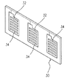
図2の集電板の変化実施例の立体組合せ図である図3に示すように、板体30と集電片32が具える貫通孔34の配置は1種のフェンス式構造を形成する。さらに図2の集電板の別種の変化実施例の立体組合せ図である図4に示すように、板体40と集電片42が具える貫通孔44の配置は1種の網状構造を形成する。すなわち図3と図4は、本考案集電板の形態が図2に示す様式に限定されないことを示しており、さらには当然各種様々な形式とすることができる。図3と図4はその内の1種に過ぎない。
As shown in FIG. 3, which is a three-dimensional combination diagram of the variation of the current collector plate of FIG. 2, the arrangement of the through
本考案の集電板は、エタノール燃料を採用する燃料電池、或いは液体燃料を採用する燃料電池、気体燃料を採用する燃料電池、固体燃料を採用する燃料電池などの各類の燃料電池に応用することができる。 The current collector plate of the present invention is applied to various types of fuel cells such as a fuel cell employing ethanol fuel, a fuel cell employing liquid fuel, a fuel cell employing gaseous fuel, and a fuel cell employing solid fuel. be able to.
上記のように本考案の特徴と機能を以下にまとめる。
1.本考案の集電板が使用する集電片は、高い導電性と抗腐食性及び/或いは防酸化の抗化学性などの特質を同時に具えるため、本考案集電板の集電能力は優越している。しかも燃料(エタノールなど)或いは電化学反応生成物の集電片表面に対する破壊を効果的に防止可能であるため、燃料電池の交換率を低下させることができる。
2.本考案の集電板中の集電片は一種の金属箔片構造を使用可能であるため、集電片は極めて薄く、よって集電板の体積と重量を大幅に低減することができる。こうして携帯式電子製品中への応用を有利とする。
3.本考案集電板の製造方法は、予め製造する集電片を利用し、点溶接、或いは粘着などの方式を利用し、集電片を板体上に圧合密着させるため、現行の製造工程技術に比べ、非常に便利かつ容易に運用可能である。よって本考案集電板は大量生産に有利である。
The features and functions of the present invention are summarized as described above.
1. The current collector used by the current collector of the present invention has characteristics such as high conductivity and anti-corrosion and / or anti-oxidation anti-chemical properties at the same time, so the current collector of the present collector has superior current collecting ability. is doing. Moreover, since the fuel (such as ethanol) or the electrochemical reaction product can be effectively prevented from being destroyed on the surface of the current collecting piece, the replacement rate of the fuel cell can be reduced.
2. Since the current collecting piece in the current collecting plate of the present invention can use a kind of metal foil piece structure, the current collecting piece is extremely thin, and thus the volume and weight of the current collecting plate can be greatly reduced. This makes it advantageous for application in portable electronic products.
3. The current collector plate manufacturing method uses a current collector piece manufactured in advance, uses a method such as spot welding or adhesion, and press-contacts the current collector piece on the plate body, so that the current manufacturing process Compared to technology, it is very convenient and easy to operate. Therefore, the current collector plate is advantageous for mass production.
1 燃料電池
10 陰極集電板
12 膜電極組板
120 膜電極組
14 陽極集電板
140 集電片
16 流道板
2 集電板
20 板体
200 集電区
200a 貫通孔
202 接続線
22 集電片
220 貫通孔
222 延伸部
30 板体
32 集電片
34 貫通孔
40 板体
42 集電片
44 貫通孔
DESCRIPTION OF SYMBOLS 1 Fuel cell 10 Cathode current collecting plate 12 Membrane electrode assembly plate 120 Membrane electrode assembly 14 Anode current collection plate 140 Current collection piece 16 Current passage plate 2
Claims (16)
該板体は少なくとも1個の集電区を具え、
該接続線は該板体の表面上に設置し、
該集電片は導電性材料は高導電性材料により製造し、該集電片はそれぞれ緊密に接着し、しかも該板体の該各集電区を覆い、かつ該各接続線において延伸接触することを特徴とする燃料電池の集電板。 Including a plate, one or more connecting wires, one or more pre-manufactured current collecting pieces,
The plate comprises at least one current collecting zone;
The connecting wire is installed on the surface of the plate body,
The current collecting piece is made of a highly conductive material, and the current collecting pieces are tightly bonded to each other, and each of the current collecting areas of the plate body is covered and stretched in contact with each connecting line. A current collector plate for a fuel cell.
Applications Claiming Priority (1)
| Application Number | Priority Date | Filing Date | Title |
|---|---|---|---|
| TW095206475U TWM298782U (en) | 2006-04-18 | 2006-04-18 | Power collecting board used for fuel cell |
Publications (1)
| Publication Number | Publication Date |
|---|---|
| JP3133071U true JP3133071U (en) | 2007-06-28 |
Family
ID=37966950
Family Applications (1)
| Application Number | Title | Priority Date | Filing Date |
|---|---|---|---|
| JP2007002734U Expired - Fee Related JP3133071U (en) | 2006-04-18 | 2007-04-17 | Fuel cell current collector |
Country Status (4)
| Country | Link |
|---|---|
| US (1) | US20080003486A1 (en) |
| JP (1) | JP3133071U (en) |
| DE (1) | DE202007004923U1 (en) |
| TW (1) | TWM298782U (en) |
Families Citing this family (3)
| Publication number | Priority date | Publication date | Assignee | Title |
|---|---|---|---|---|
| JP5183080B2 (en) * | 2007-02-27 | 2013-04-17 | 三洋電機株式会社 | Fuel cell |
| TWI382584B (en) * | 2008-02-19 | 2013-01-11 | Asia Pacific Fuel Cell Tech | The structure of the fuel cell module |
| JP5395625B2 (en) * | 2009-11-11 | 2014-01-22 | 日東電工株式会社 | Wiring circuit board and fuel cell |
Family Cites Families (1)
| Publication number | Priority date | Publication date | Assignee | Title |
|---|---|---|---|---|
| DK1109937T3 (en) * | 1998-09-02 | 2009-03-09 | Diadexus Inc | Procedures for diagnosis, monitoring, staging and imaging for various cancers |
-
2006
- 2006-04-18 TW TW095206475U patent/TWM298782U/en not_active IP Right Cessation
-
2007
- 2007-04-03 DE DE202007004923U patent/DE202007004923U1/en not_active Expired - Lifetime
- 2007-04-16 US US11/735,514 patent/US20080003486A1/en not_active Abandoned
- 2007-04-17 JP JP2007002734U patent/JP3133071U/en not_active Expired - Fee Related
Also Published As
| Publication number | Publication date |
|---|---|
| US20080003486A1 (en) | 2008-01-03 |
| DE202007004923U1 (en) | 2007-06-21 |
| TWM298782U (en) | 2006-10-01 |
Similar Documents
| Publication | Publication Date | Title |
|---|---|---|
| JP4702304B2 (en) | Fuel cell separator, fuel cell separator manufacturing method, and fuel cell | |
| US8003275B2 (en) | Monopolar membrane-electrode assembly | |
| US9240608B2 (en) | Fuel cell assembly | |
| US20050202305A1 (en) | Fuel cell apparatus and method of fabrication | |
| JP2006156386A (en) | Metal separator for fuel cell, method for producing the same, and fuel cell stack including the same | |
| JP2000138067A (en) | Fuel cell gas separator, fuel cell using the fuel cell gas separator, and method of manufacturing fuel cell gas separator | |
| US9793554B2 (en) | Fuel cell separator and fuel cell | |
| US20180375113A1 (en) | Method for producing fuel cell separator | |
| CA2482488A1 (en) | Composite films for electrochemical devices | |
| JPH10255823A (en) | Solid high polymer fuel cell | |
| JPH11162478A (en) | Separator for fuel cell | |
| JP3133071U (en) | Fuel cell current collector | |
| US20090233138A1 (en) | Membrane Electrode and Current Collecting Board Assembly of Electrochemical Cell, and Electrochemical Cell Module | |
| WO2001003214A1 (en) | Separator of solid-polymer fuel cell, method of manufacture thereof, and solid-polymer fuel cell | |
| CN100463265C (en) | monopolar membrane electrode assembly | |
| JP2003217611A (en) | Separator for fuel cell, and fuel cell | |
| EP2095455A1 (en) | Solid oxide fuel cell | |
| JP3130802U (en) | Fuel cell | |
| JP2001325966A (en) | Separator for fuel cell and fuel cell | |
| JP3133191U (en) | Cathodic flow plate for use in fuel cells | |
| KR20080065545A (en) | Flexible Graphite / Metal Distribution Plate For Fuel Cell Assembly | |
| CN201041818Y (en) | Collector plate for fuel cell | |
| US8137862B2 (en) | Fuel cell | |
| KR20070093734A (en) | Separator for fuel cell and fuel cell comprising same | |
| JP3123244U (en) | Fuel cell device |
Legal Events
| Date | Code | Title | Description |
|---|---|---|---|
| R150 | Certificate of patent or registration of utility model |
Free format text: JAPANESE INTERMEDIATE CODE: R150 |
|
| LAPS | Cancellation because of no payment of annual fees |