JP3110527U - Folding assist mechanism for folding load carrier in retractable load carrier lifting device - Google Patents
Folding assist mechanism for folding load carrier in retractable load carrier lifting device Download PDFInfo
- Publication number
- JP3110527U JP3110527U JP2005000850U JP2005000850U JP3110527U JP 3110527 U JP3110527 U JP 3110527U JP 2005000850 U JP2005000850 U JP 2005000850U JP 2005000850 U JP2005000850 U JP 2005000850U JP 3110527 U JP3110527 U JP 3110527U
- Authority
- JP
- Japan
- Prior art keywords
- loading platform
- folding
- side member
- end side
- load receiving
- Prior art date
- Legal status (The legal status is an assumption and is not a legal conclusion. Google has not performed a legal analysis and makes no representation as to the accuracy of the status listed.)
- Expired - Fee Related
Links
Images


Landscapes
- Vehicle Step Arrangements And Article Storage (AREA)
Abstract
【課題】荷受台と一体化した感じで補助機能を発揮するトーションバーを配設することができ、意匠的に非常に優れた格納式荷受台昇降装置における折畳み式荷受台の折畳み補助機構を提供する。
【解決手段】荷台1に荷受台5が昇降自在に設けられるとともに、荷受台5が少なくとも2枚の先端側部材51と基端側部材52とに分割されて折畳み自在に構成され、荷台1下方の格納位置と荷台1から外方に突出配置されて昇降動作を行う作業位置Cとの間でスライド自在になされた格納式荷受台昇降装置2において、荷受台5の基端側部材52もしくは先端側部材51の一側部にトーションバー71の一端部が摺動自在に設けられるとともに、トーションバー71の途中部が隣接する先端側部材51側もしくは基端側部材52側に導かれてその他側部に向けて折り返され、先端側部材51もしくは基端側部材52の他側部側で軸芯を中心とする回転を阻止された状態で止着されている。
【選択図】 図1
PROBLEM TO BE SOLVED: To provide a folding assist mechanism for a folding load receiver in a retractable load receiver lifting device capable of arranging a torsion bar that exhibits an auxiliary function with a feeling integrated with a load receiver and having a very excellent design. To do.
A loading platform 5 is provided on the loading platform 1 so as to be movable up and down, and the loading platform 5 is divided into at least two front end members 51 and a proximal end member 52 so as to be foldable. In the retractable load receiving and lifting device 2 that is slidable between the storage position and the work position C that protrudes outward from the loading platform 1 and performs the lifting operation, the proximal end side member 52 or the distal end of the load receiving platform 5 One end portion of the torsion bar 71 is slidably provided on one side portion of the side member 51, and the middle portion of the torsion bar 71 is guided to the adjacent distal end member 51 side or proximal end member 52 side to the other side. It is folded back toward the portion and is fastened in a state in which rotation around the axis is prevented on the other side portion side of the distal end side member 51 or the proximal end side member 52.
[Selection] Figure 1
Description
本考案は、荷受台昇降装置における折畳み式の荷受台に関し、具体的にはこの荷受台を構成する各分割部材を折畳む際にこの動作を補助する折畳み補助機構に関するものである。 The present invention relates to a foldable load receiving platform in a load receiving platform lifting apparatus, and more particularly to a folding assist mechanism that assists this operation when folding each divided member constituting the load receiving platform.
従来、荷台に荷受台が昇降自在に設けられるとともに、この荷受台が例えば2枚の分割部材に分割されて両者がヒンジ部を介して折畳み自在に構成され、荷台下方の格納位置と荷台から外方に突出配置されて昇降動作を行う作業位置との間でスライド自在になされた格納式荷受台昇降装置が提供されている。 Conventionally, a loading platform is provided on the loading platform so that it can be moved up and down, and the loading platform is divided into, for example, two divided members, both of which are configured to be foldable via a hinge portion. There is provided a retractable load receiving table elevating device that is slidable between a work position that protrudes in the direction and performs an elevating operation.
そして、このように折り畳む折畳み式の荷受台では、上記ヒンジ部を利用してコイル状スプリングを設け、荷受台を展開する際もしくは折畳む際に捩れ力を発生させたコイル状スプリングで補助することによって、展開もしくは折畳み時に必要な力を軽減させるようにしていた(例えば、特許文献1参照。)。
しかしながら、上記従来のように展開もしくは折畳み時の動作を補助する折畳み補助機構としてコイル状スプリングを設けているものでは、その機能を発揮する上でコイル状スプリングが大型になる。このため荷受台を折り畳んだ際にこの大型のコイル状スプリングが外部に露出して見た目が悪く、これが通行人等に驚異を与えかねず意匠的に問題があった。 However, in the case where a coiled spring is provided as a folding assist mechanism for assisting the operation during expansion or folding as in the conventional case, the coiled spring becomes large in order to perform its function. For this reason, when the load receiving base is folded, the large coiled spring is exposed to the outside, which makes it look bad.
上記の目的を達成するため、請求項1に係る考案の格納式荷受台昇降装置における折畳み式荷受台の折畳み補助機構は、荷台に荷受台が昇降自在に設けられるとともに、荷受台が少なくとも2枚の先端側部材と基端側部材とに分割されて折畳み自在に構成され、荷台下方の格納位置と荷台から外方に突出配置されて昇降動作を行う作業位置との間でスライド自在になされた格納式荷受台昇降装置において、前記荷受台の基端側部材もしくは先端側部材の一側部にトーションバーの一端部が摺動自在に設けられるとともに、当該トーションバーの途中部が隣接する先端側部材側もしくは基端側部材に導かれてその他側部に向けて折り返され、上記先端側部材もしくは基端側部材の他側部側で軸芯を中心とする回転を阻止された状態で止着されてなるものである。 In order to achieve the above object, the folding assist mechanism of the folding load receiver in the retractable load receiver lifting device according to the first aspect of the present invention is provided with a load receiver that can be raised and lowered on the load carrier, and at least two load receivers. It is divided into a front end side member and a base end side member, and is configured to be foldable, and is slidable between a storage position below the loading platform and a working position that protrudes outward from the loading platform and performs a lifting operation. In the retractable cargo receiver lifting device, one end of the torsion bar is slidably provided on one side of the base end member or the front end member of the load receiver, and the middle of the torsion bar is adjacent to the front end side Guided to the member side or base end side member, folded back toward the other side, and fixed in a state where rotation around the shaft core is prevented on the other side of the tip end side member or base end side member Been Is shall.
本考案によれば、荷受台の展開時もしくは折畳み時においてトーションバーによって当該荷受台を持ち上げる動作を補助する機能を発揮することができ、しかも荷受台と一体化した感じでトーションバーを配設することができ、意匠的に非常に優れた荷受台昇降装置を提供することができる。 According to the present invention, the function of assisting the operation of lifting the load receiving table by the torsion bar when the load receiving table is unfolded or folded can be exhibited, and the torsion bar is arranged in a manner integrated with the load receiving table. It is possible to provide a load receiving table lifting apparatus that is very excellent in design.
以下、本考案の実施の形態について図面を参照して説明する。 Embodiments of the present invention will be described below with reference to the drawings.
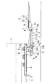
図1は、格納式荷受台昇降装置の概略構成を示している。 FIG. 1 shows a schematic configuration of a retractable cargo receiving table lifting device.
図1において、1は車輌の車枠11上に搭載された荷台で、この荷台1の後端下方に格納式荷受台昇降装置2が設けられている。
In FIG. 1,
格納式荷受台昇降装置2は、車枠11に設けられた取付部材3と、この取付部材3にリンク機構4を介して設けられた荷受台5とを備えている。
The retractable load receiving table lifting / lowering
取付部材3は、前記車枠11の後端部に前後方向に配設されたスライドレール12に沿って前後方向にスライド自在に設けられている。
The
具体的には、スライドレール12は例えばI形鋼からなり、その途中のウエブを垂直にして配置され、このスライドレール12にスライド部材3が図示しないスライド機構を介してスライド自在に設けられている。スライド機構としては、例えばスライドレール12の上下フランジを上下から挟んだ状態で摺接するスライドパッドと、スライドレール12のウエブの外側面をスライド方向に転動するローラなどで構成されている。
Specifically, the
この取付部材3には、駆動軸6が略水平に軸支されている。駆動軸6には駆動アーム61の基端部が一体に固設され、この駆動アーム61の先端部に同じく取付部材3に設けられたリフトシリンダ62の伸縮ロッド62aの先端が連結されている。
A
また、駆動軸6には回動ブラケット63の基端部が一体に設けられており、回動ブラケット63の途中部に後述するリフトリンク41の基端部が枢支されている。
Further, the
前記リンク機構4は、リフトリンク41と連結リンク42とで構成されている。
The
リフトリンク41は、その基端部が前記回動ブラケット63の途中部に枢軸41aにより枢支されている。
The
このリフトリンク41の基端部寄りの下面には、前記回動ブラケット63の先端部に設けられた当接ボルト64が当接可能に構成されており、当接ボルト64がリフトリンク41の基端部寄りの部位に下方から当接することで、前記リフトシリンダ62の伸縮動作を前記駆動アーム61、駆動軸6を介して回動ブラケット63の回動動作としてリフトリンク41に伝達することができ、これによりリフトリンク41が上下に回動する。
A
連結リンク42は、その基端部が前記取付部材3に枢軸42aにより枢支されている。
The base end of the connecting
上述したスライドレール12、取付部材3、リンク機構4、駆動軸6等の各部材は車枠11の両側に左右一対設けられており、左右の取付部材3はスライドレール12を同調してスライドするように連結部材3aによって連結されている。
A pair of left and right members such as the
前記荷受台5は、先端側部材51と基端側部材52とで構成されており、これら先端側部材51と基端側部材52とはヒンジ53によって該先端側部材51が基端側部材52の上面に2つ折り自在になされている。
The load receiving
基端側部材52の基端部左右両側には、ブラケット54を介してその上部に前記左右の連結リンク42の先端部が枢軸42bにより枢支され、その下部に前記左右のリフトリンク41の先端部が枢軸41bにより枢支されている。
On the left and right sides of the base end portion of the base
また、先端側部材51の先端は楔状に形成されており、荷受台5が地上に達した際に図1の一点鎖線で示すように傾動することで、この先端が地上に段差なく接地するようになされている。
Further, the tip of the
次に、このように構成された格納式荷受台昇降装置の動作について説明する。 Next, the operation of the retractable load receiving device lifting apparatus configured as described above will be described.
格納式荷受台昇降装置2の基本的な動作としては、この格納式荷受台昇降装置2が、前述した移動手段の操作により、荷受台5を折り畳んだ状態で取付部材3をスライドレール12の前端部にスライドさせて格納する格納位置A(図2参照)と、取付部材3をスライドレール12の後端部にスライドさせて折り畳んだ荷受台5を先端側部材51と基端側部材52とが水平状態になるように展開するとともに、その展開した荷受台5の折り畳みを行う展開・折り畳み位置B(図3参照)と、荷受台5を展開した状態で取付部材3をスライドレール12の途中位置にスライドさせてこの荷受台5を地上と荷台1の床面との間で昇降作動させる昇降作業位置C(図1参照)とに配置可能になされている。
As a basic operation of the retractable load receiving device lifting / lowering
そして、まず、図2に示すように格納位置Aに配置された格納式荷受台昇降装置2により荷物の積降ろし作業を行う場合は、この状態で取付部材3をスライドレール12の前端部から後端部にスライドさせることで、荷受台5を折り畳んだ状態で格納式荷受台昇降装置2を図3に示す展開・折り畳み位置Bに配置させる。
First, when the loading / unloading operation of the load is performed by the retractable load receiving device lifting / lowering
このようにして格納式荷受台昇降装置2が展開・折り畳み位置Bに配置されると、折り畳まれた荷受台5の先端側部材51を後方に回動させて基端側部材52と先端側部材51とが水平になるように展開する。この荷受台5の展開は、当該荷受台5全体を荷台1及び車枠11の後方に引き出した状態で行っているため、荷受台5が荷台1及び車枠11に干渉することがない。
When the retractable load receiving
そして、この状態で格納式荷受台昇降装置2を上記展開・折り畳み位置Bから昇降作業位置C側にスライドさせて取付部材3が昇降作業位置Cに達すると図示しない位置決め手段によって格納式荷受台昇降装置2を当該昇降作業位置Cで位置決めする。
In this state, when the retractable load receiving
これにより、荷受台5はリフトシリンダ62の伸縮動作により地上と荷台1の床面との間で昇降可能な状態になり、この昇降動作によって荷受台5を通じて地上と荷台1との間で荷物の積卸し作業を行う。
As a result, the load receiving
次に、荷物の積降ろし作業が終了して格納式荷受台昇降装置2を格納する場合には、格納式荷受台昇降装置2を昇降作業位置Cから一旦、展開・折り畳み位置Bに配置し、この位置において荷受台5の先端側部材51を折り畳む。この荷受台5の折り畳みは、前述した荷受台5の展開と同様に荷受台5全体を荷台1及び車枠11の後方に引き出した状態で行なっており、このため荷受台5が荷台1及び車枠11と干渉することはない。
Next, when the loading / unloading operation of the load is completed and the retractable load receiving device lifting / lowering
そして、このように荷受台5を折り畳んだ状態で格納式荷受台昇降装置2を展開・折り畳み位置Bから格納位置A側にスライドさせて格納位置に配置する。
Then, with the load receiving
ところで、上述のように構成された格納式荷受台昇降装置2において折畳み式の荷受台5には折畳み補助機構7が設けられている。
By the way, the folding type load receiving
折畳み補助機構7は、図3乃至図5に示すようにトーションバー71を備えている。具体的には、トーションバー71は、図6に示すように一端部72が基端側部材52の一側部に摺動機構8を介して摺動自在に設けられるとともに、途中部73が基端側部材52寄りの先端側部材51に導かれてこの先端側部材51の基端側部材52寄りで他側部側に折り返され、且つ他端部74が上記先端側部材51の他側部側で軸芯を中心とする回転を阻止された状態で止着されている。
The
上記摺動機構8は、基端側部材52の一側部に設けられ、上記トーションバー71の一端部72が挿通する挿通孔82を有する円柱状の支持部材81からなり、一端部72を軸芯方向に摺動自在に支持している。また、この支持部材81は後述する先端側部材51の回動に伴う一端部72の角度変化に対応するように基端側部材52の一側部に対して中心軸を中心にして回動可能に設けられている。
The
このように構成された折畳み補助機構7は、図4に示すように先端側部材51が垂直方向に起立した状態ではトーションバー71には捩れが生じていない所謂ニュートラル状態になっている。
As shown in FIG. 4, the
そして、この状態から例えば図5に示すように先端側部材51を基端側部材52と略同一平面になるように下方に回動(展開)させることで、荷受台5の幅方向に伸びているトーションバー71の途中部73から他端部74に亘ってその回動に相当する分の捩れが発生する。従って、先端側部材51を図5に示す状態から図4に示す状態まで回動させる際には上記捩れによる反発力がこの回動方向に働き、これによって作業者による回動動作を補助することができる。
Then, from this state, for example, as shown in FIG. 5, the distal
一方、図4に示す状態から先端側部材51を図3に示すように基端側部材52上に下方に回動(折畳み)させることによっても、荷受台5の幅方向に伸びているトーションバー71の途中部73から他端部74に亘ってその回動に相当する分の捩れが発生する。従って、先端側部材51を図3に示す状態から図4に示す状態まで回動させる際にも上述と同様に上記捩れによる反発力がこの回動方向に働き、これによって作業者による回動動作を補助することができる。この場合、先端側部材51の姿勢変化に伴ってトーションバー71の一端部72が摺動機構8によって摺動することで当該姿勢変化に追従しながら上述した補助機能を発揮する。
On the other hand, the torsion bar extending in the width direction of the
つまり、先端側部材51の展開時もしくは折畳み時において当該先端側部材51を図4に示すように垂直方向に持ち上げて起立させる動作時にはトーションバー71がこの動作を補助する機能を発揮する。
That is, the
しかも、荷受台5と一体化した感じで補助機能を発揮するトーションバー71を配設することができ、意匠的に非常に優れた荷受台昇降装置を提供することができる。
Moreover, a
図7は、折畳み補助機構の他の構成を示している。 FIG. 7 shows another configuration of the folding assist mechanism.
この折畳み補助機構7は、トーションバー71の一端部72を摺動自在に支持する摺動機構8が異なった構成になっている。
This folding assist
具体的には、この摺動機構8は、基端側部材52の側面に溝部52aを前後方向に形成し、この溝部52a内に一端部72の先端を摺動自在に嵌入することによって構成されている。なお、トーションバー71の他の配置などは前述したものと同様である。
Specifically, the sliding
このような摺動機構8を備えて折畳み補助機構7を構成することによっても摺動機構8によって先端側部材51の姿勢変化に追従しながら上述した折畳み補助機構7と同様な補助機構を発揮することができ、同様な効果を奏することができる。
The
図8は、折畳み補助機構のさらに他の構成を示している。 FIG. 8 shows still another configuration of the folding assist mechanism.
この折畳み補助機構7は、トーションバー71の一端部72を摺動自在に支持する摺動機構8が異なった構成であるとともに、トーションバー71の途中部の配置位置が異なっている。
The
具体的には、摺動機構8は、トーションバー71の一端部72が長孔72aを有する長尺状の平板部材で構成されており、この平板部材の長孔72aに基端側部材52の側面に設けられたピン52bが摺動自在に嵌入されている。
Specifically, the sliding
また、トーションバー71の途中部から先端側部材51に保持された他端部に亘っては前述と同様に棒状に形成されて上記平板部材と一体的に連結されており、この棒状部71aが先端側部材51を基端側部材52上に折畳んだ状態でこれら先端側部材51と基端側部材52との連結部分後端側にヒンジ53を介して支持されるように配設されている。具体的には先端側部材51を基端側部材52上に折畳んだ状態においてヒンジ53の後端側となる部分を膨出形成しこの膨出部53aでトーションバー71の上記棒状部71aを支持している。
Further, from the middle portion of the
このように折畳み補助機構7を構成することによっても摺動機構8によって先端側部材51の姿勢変化に追従しながら上述した折畳み補助機構7と同様な補助機構を発揮することができ、同様な効果を奏することができる。
By configuring the
なお、上述した実施形態は、あくまでも本考案の好適な実施態様を示すものであって、本考案はこれに限定されることなく、その範囲内において種々設計変更可能である。 Note that the above-described embodiment is merely a preferred embodiment of the present invention, and the present invention is not limited to this, and various design changes can be made within the scope thereof.
例えば、この実施の形態では荷受台5を昇降させる昇降機構としてリンク機構4について説明したが、昇降機構はこれに限定されるものではなく、本考案は折り畳むタイプの荷受台5全般に適用することができる。
For example, in this embodiment, the
また、荷受台5は、2つ折りに限らず、3つ折りやそれ以上のものでも本考案の折畳み補助機構を適用することができる。
Moreover, the folding support mechanism of this invention can be applied to the
さらに、トーションバー71を基端側部材52と先端側部材51とで前述とは逆に配設してもよい。即ち、先端側部材51の一側部にトーションバーの一端部を摺動自在に設けるとともに、当該トーションバーの途中部を隣接する基端側部材52に導いてその他側部に向けて折り返し、上記基端側部材52の他側部側で軸芯を中心とする回転を阻止した状態で止着するようにしてもよい。
Further, the
1 荷台
2 格納式荷受台昇降装置
5 荷受台
51 先端側部材
52 基端側部材
7 折畳み補助機構
71 トーションバー
72 一端部
73 途中部
74 他端部
8 摺動機構
DESCRIPTION OF
Claims (1)
前記荷受台の基端側部材もしくは先端側部材の一側部にトーションバーの一端部が摺動自在に設けられるとともに、当該トーションバーの途中部が隣接する先端側部材側もしくは基端側部材に導かれてその他側部に向けて折り返され、上記先端側部材もしくは基端側部材の他側部側で軸芯を中心とする回転を阻止された状態で止着されてなることを特徴とする格納式荷受台昇降装置における折畳み式荷受台の折畳み補助機構。
The loading platform is provided on the loading platform so as to be movable up and down, and the loading platform is divided into at least two distal end members and a proximal end member so as to be foldable, and protrudes outward from the storage position below the loading platform and the loading platform. In the retractable loading platform lifting device that is slidable between the work position that is arranged and performs the lifting operation,
One end portion of the torsion bar is slidably provided at one side portion of the proximal end member or the distal end side member of the load receiving platform, and the intermediate portion of the torsion bar is adjacent to the adjacent distal end member side or proximal end member. It is guided and folded back toward the other side, and is fixed in a state where rotation around the axis is prevented on the other side of the distal end side member or the base end side member. Folding assist mechanism for the folding load carrier in the retractable load carrier lifting device.
Priority Applications (1)
| Application Number | Priority Date | Filing Date | Title |
|---|---|---|---|
| JP2005000850U JP3110527U (en) | 2005-02-22 | 2005-02-22 | Folding assist mechanism for folding load carrier in retractable load carrier lifting device |
Applications Claiming Priority (1)
| Application Number | Priority Date | Filing Date | Title |
|---|---|---|---|
| JP2005000850U JP3110527U (en) | 2005-02-22 | 2005-02-22 | Folding assist mechanism for folding load carrier in retractable load carrier lifting device |
Publications (1)
| Publication Number | Publication Date |
|---|---|
| JP3110527U true JP3110527U (en) | 2005-06-23 |
Family
ID=43273063
Family Applications (1)
| Application Number | Title | Priority Date | Filing Date |
|---|---|---|---|
| JP2005000850U Expired - Fee Related JP3110527U (en) | 2005-02-22 | 2005-02-22 | Folding assist mechanism for folding load carrier in retractable load carrier lifting device |
Country Status (1)
| Country | Link |
|---|---|
| JP (1) | JP3110527U (en) |
Cited By (1)
| Publication number | Priority date | Publication date | Assignee | Title |
|---|---|---|---|---|
| JP2015182530A (en) * | 2014-03-24 | 2015-10-22 | 新明和工業株式会社 | Load receiving platform lift device |
-
2005
- 2005-02-22 JP JP2005000850U patent/JP3110527U/en not_active Expired - Fee Related
Cited By (1)
| Publication number | Priority date | Publication date | Assignee | Title |
|---|---|---|---|---|
| JP2015182530A (en) * | 2014-03-24 | 2015-10-22 | 新明和工業株式会社 | Load receiving platform lift device |
Similar Documents
| Publication | Publication Date | Title |
|---|---|---|
| JP3110527U (en) | Folding assist mechanism for folding load carrier in retractable load carrier lifting device | |
| JP3110174U (en) | Load receiving device fall prevention device in retractable load receiving device lifting device | |
| JP3110280U (en) | Folding-type load receiving platform in the load receiving platform lifting device | |
| JP3110173U (en) | Retractable loading platform lifting device | |
| JP4037399B2 (en) | Retractable loading platform lifting device | |
| JP4291332B2 (en) | Load receiving device storage device in retractable load receiving device lifting device | |
| JP3110613U (en) | Load receiving device storage device in retractable load receiving device lifting device | |
| JP3131617B2 (en) | lift device | |
| JP4322862B2 (en) | Vehicle equipped with retractable loading platform lifting device | |
| JP3110508U (en) | Retractable cradle lifting device and method for attaching it to the body frame | |
| JP3110175U (en) | Retractable bending prevention structure of retractable loading platform lifting device | |
| JP2015182530A (en) | Load receiving platform lift device | |
| JP3110121U (en) | Retractable loading platform lifting device | |
| JP3110634U (en) | Slide drive device in retractable load carrier lifting device | |
| JP3110271U (en) | Foldable load receiving platform for retractable load receiving device | |
| JP5160348B2 (en) | Rotating retractable cradle lifting device | |
| JP2020050131A (en) | Retractable loading platform lifting device | |
| JP4037400B2 (en) | Retractable loading platform lifting device | |
| JP4197219B2 (en) | Retractable loading platform lifting device | |
| JP4197223B2 (en) | Positioning device for loading platform in lifting platform lifting device | |
| JP2005014827A (en) | Retractable cradle lifting device with bumper function | |
| JP4172989B2 (en) | Loading platform lifting device | |
| JP3154920U (en) | Loading platform lifting device | |
| JP4236385B2 (en) | Slide mechanism in retractable load receiving device lifting device | |
| JP4188660B2 (en) | Loading platform lifting device |
Legal Events
| Date | Code | Title | Description |
|---|---|---|---|
| R150 | Certificate of patent or registration of utility model |
Free format text: JAPANESE INTERMEDIATE CODE: R150 |
|
| FPAY | Renewal fee payment (event date is renewal date of database) |
Free format text: PAYMENT UNTIL: 20090511 Year of fee payment: 4 |
|
| FPAY | Renewal fee payment (event date is renewal date of database) |
Free format text: PAYMENT UNTIL: 20100511 Year of fee payment: 5 |
|
| LAPS | Cancellation because of no payment of annual fees |