JP2024538244A - Generating a bubble jet to break up and remove eye floaters - Google Patents
Generating a bubble jet to break up and remove eye floaters Download PDFInfo
- Publication number
- JP2024538244A JP2024538244A JP2024524633A JP2024524633A JP2024538244A JP 2024538244 A JP2024538244 A JP 2024538244A JP 2024524633 A JP2024524633 A JP 2024524633A JP 2024524633 A JP2024524633 A JP 2024524633A JP 2024538244 A JP2024538244 A JP 2024538244A
- Authority
- JP
- Japan
- Prior art keywords
- laser
- floaters
- bubble
- bubble jet
- cavitation bubbles
- Prior art date
- Legal status (The legal status is an assumption and is not a legal conclusion. Google has not performed a legal analysis and makes no representation as to the accuracy of the status listed.)
- Pending
Links
Images


Classifications
-
- A—HUMAN NECESSITIES
- A61—MEDICAL OR VETERINARY SCIENCE; HYGIENE
- A61F—FILTERS IMPLANTABLE INTO BLOOD VESSELS; PROSTHESES; DEVICES PROVIDING PATENCY TO, OR PREVENTING COLLAPSING OF, TUBULAR STRUCTURES OF THE BODY, e.g. STENTS; ORTHOPAEDIC, NURSING OR CONTRACEPTIVE DEVICES; FOMENTATION; TREATMENT OR PROTECTION OF EYES OR EARS; BANDAGES, DRESSINGS OR ABSORBENT PADS; FIRST-AID KITS
- A61F9/00—Methods or devices for treatment of the eyes; Devices for putting in contact-lenses; Devices to correct squinting; Apparatus to guide the blind; Protective devices for the eyes, carried on the body or in the hand
- A61F9/007—Methods or devices for eye surgery
- A61F9/008—Methods or devices for eye surgery using laser
- A61F9/00825—Methods or devices for eye surgery using laser for photodisruption
- A61F9/0084—Laser features or special beam parameters therefor
-
- A—HUMAN NECESSITIES
- A61—MEDICAL OR VETERINARY SCIENCE; HYGIENE
- A61F—FILTERS IMPLANTABLE INTO BLOOD VESSELS; PROSTHESES; DEVICES PROVIDING PATENCY TO, OR PREVENTING COLLAPSING OF, TUBULAR STRUCTURES OF THE BODY, e.g. STENTS; ORTHOPAEDIC, NURSING OR CONTRACEPTIVE DEVICES; FOMENTATION; TREATMENT OR PROTECTION OF EYES OR EARS; BANDAGES, DRESSINGS OR ABSORBENT PADS; FIRST-AID KITS
- A61F9/00—Methods or devices for treatment of the eyes; Devices for putting in contact-lenses; Devices to correct squinting; Apparatus to guide the blind; Protective devices for the eyes, carried on the body or in the hand
- A61F9/007—Methods or devices for eye surgery
- A61F9/008—Methods or devices for eye surgery using laser
- A61F2009/00844—Feedback systems
- A61F2009/00846—Eyetracking
-
- A—HUMAN NECESSITIES
- A61—MEDICAL OR VETERINARY SCIENCE; HYGIENE
- A61F—FILTERS IMPLANTABLE INTO BLOOD VESSELS; PROSTHESES; DEVICES PROVIDING PATENCY TO, OR PREVENTING COLLAPSING OF, TUBULAR STRUCTURES OF THE BODY, e.g. STENTS; ORTHOPAEDIC, NURSING OR CONTRACEPTIVE DEVICES; FOMENTATION; TREATMENT OR PROTECTION OF EYES OR EARS; BANDAGES, DRESSINGS OR ABSORBENT PADS; FIRST-AID KITS
- A61F9/00—Methods or devices for treatment of the eyes; Devices for putting in contact-lenses; Devices to correct squinting; Apparatus to guide the blind; Protective devices for the eyes, carried on the body or in the hand
- A61F9/007—Methods or devices for eye surgery
- A61F9/008—Methods or devices for eye surgery using laser
- A61F2009/00861—Methods or devices for eye surgery using laser adapted for treatment at a particular location
- A61F2009/00863—Retina
-
- A—HUMAN NECESSITIES
- A61—MEDICAL OR VETERINARY SCIENCE; HYGIENE
- A61F—FILTERS IMPLANTABLE INTO BLOOD VESSELS; PROSTHESES; DEVICES PROVIDING PATENCY TO, OR PREVENTING COLLAPSING OF, TUBULAR STRUCTURES OF THE BODY, e.g. STENTS; ORTHOPAEDIC, NURSING OR CONTRACEPTIVE DEVICES; FOMENTATION; TREATMENT OR PROTECTION OF EYES OR EARS; BANDAGES, DRESSINGS OR ABSORBENT PADS; FIRST-AID KITS
- A61F9/00—Methods or devices for treatment of the eyes; Devices for putting in contact-lenses; Devices to correct squinting; Apparatus to guide the blind; Protective devices for the eyes, carried on the body or in the hand
- A61F9/007—Methods or devices for eye surgery
- A61F9/008—Methods or devices for eye surgery using laser
- A61F2009/00861—Methods or devices for eye surgery using laser adapted for treatment at a particular location
- A61F2009/00874—Vitreous
-
- A—HUMAN NECESSITIES
- A61—MEDICAL OR VETERINARY SCIENCE; HYGIENE
- A61F—FILTERS IMPLANTABLE INTO BLOOD VESSELS; PROSTHESES; DEVICES PROVIDING PATENCY TO, OR PREVENTING COLLAPSING OF, TUBULAR STRUCTURES OF THE BODY, e.g. STENTS; ORTHOPAEDIC, NURSING OR CONTRACEPTIVE DEVICES; FOMENTATION; TREATMENT OR PROTECTION OF EYES OR EARS; BANDAGES, DRESSINGS OR ABSORBENT PADS; FIRST-AID KITS
- A61F9/00—Methods or devices for treatment of the eyes; Devices for putting in contact-lenses; Devices to correct squinting; Apparatus to guide the blind; Protective devices for the eyes, carried on the body or in the hand
- A61F9/007—Methods or devices for eye surgery
- A61F9/008—Methods or devices for eye surgery using laser
- A61F2009/00878—Planning
-
- A—HUMAN NECESSITIES
- A61—MEDICAL OR VETERINARY SCIENCE; HYGIENE
- A61F—FILTERS IMPLANTABLE INTO BLOOD VESSELS; PROSTHESES; DEVICES PROVIDING PATENCY TO, OR PREVENTING COLLAPSING OF, TUBULAR STRUCTURES OF THE BODY, e.g. STENTS; ORTHOPAEDIC, NURSING OR CONTRACEPTIVE DEVICES; FOMENTATION; TREATMENT OR PROTECTION OF EYES OR EARS; BANDAGES, DRESSINGS OR ABSORBENT PADS; FIRST-AID KITS
- A61F9/00—Methods or devices for treatment of the eyes; Devices for putting in contact-lenses; Devices to correct squinting; Apparatus to guide the blind; Protective devices for the eyes, carried on the body or in the hand
- A61F9/007—Methods or devices for eye surgery
- A61F9/008—Methods or devices for eye surgery using laser
- A61F2009/00885—Methods or devices for eye surgery using laser for treating a particular disease
-
- A—HUMAN NECESSITIES
- A61—MEDICAL OR VETERINARY SCIENCE; HYGIENE
- A61F—FILTERS IMPLANTABLE INTO BLOOD VESSELS; PROSTHESES; DEVICES PROVIDING PATENCY TO, OR PREVENTING COLLAPSING OF, TUBULAR STRUCTURES OF THE BODY, e.g. STENTS; ORTHOPAEDIC, NURSING OR CONTRACEPTIVE DEVICES; FOMENTATION; TREATMENT OR PROTECTION OF EYES OR EARS; BANDAGES, DRESSINGS OR ABSORBENT PADS; FIRST-AID KITS
- A61F9/00—Methods or devices for treatment of the eyes; Devices for putting in contact-lenses; Devices to correct squinting; Apparatus to guide the blind; Protective devices for the eyes, carried on the body or in the hand
- A61F9/007—Methods or devices for eye surgery
- A61F9/008—Methods or devices for eye surgery using laser
- A61F2009/00897—Scanning mechanisms or algorithms
Landscapes
- Health & Medical Sciences (AREA)
- Ophthalmology & Optometry (AREA)
- Heart & Thoracic Surgery (AREA)
- Vascular Medicine (AREA)
- Optics & Photonics (AREA)
- Surgery (AREA)
- Engineering & Computer Science (AREA)
- Biomedical Technology (AREA)
- Physics & Mathematics (AREA)
- Nuclear Medicine, Radiotherapy & Molecular Imaging (AREA)
- Life Sciences & Earth Sciences (AREA)
- Animal Behavior & Ethology (AREA)
- General Health & Medical Sciences (AREA)
- Public Health (AREA)
- Veterinary Medicine (AREA)
- Laser Surgery Devices (AREA)
- Lasers (AREA)
Abstract
特定の実施形態では、眼の硝子体中の浮遊物を治療するための眼科レーザシステムは、気泡噴流を生成するキャビテーション気泡を生じさせて浮遊物を治療するために、レーザパルスを浮遊物に向けて誘導するレーザデバイスを含む。いくつかの例では、レーザデバイスは、気泡噴流を生成するキャビテーション気泡を形成する複数のビームにレーザビームを分割するビームマルチプレクサを含む。いくつかの例では、レーザデバイスは、気泡噴流を生成するキャビテーション気泡を形成するパルスパターンに従い、レーザパルスを浮遊物に向けて誘導する。
In certain embodiments, an ophthalmic laser system for treating floaters in the vitreous of an eye includes a laser device that directs laser pulses toward the floaters to create cavitation bubbles that generate a bubble jet to treat the floaters. In some examples, the laser device includes a beam multiplexer that splits the laser beam into multiple beams that form the cavitation bubbles that generate the bubble jet. In some examples, the laser device directs the laser pulses toward the floaters according to a pulse pattern that forms the cavitation bubbles that generate the bubble jet.
Description
本開示は、概して、レーザビトレオライシスシステムに関し、より詳細には、眼浮遊物を破砕及び除去するために気泡噴流を発生させることに関する。 The present disclosure relates generally to laser vitreolysis systems and, more particularly, to generating a bubble jet to break up and remove ocular floaters.
眼浮遊物は、凝集して網膜上に影を落とす可能性がある微細なコラーゲン線維であり、これにより患者の視界が妨げられる。レーザビトレオライシスでは、眼浮遊物を治療するために、レーザビームが硝子体中に誘導され得る。浮遊物を分解して視力を改善するためにレーザビームが使用され得る。 Eye floaters are microscopic collagen fibers that can clump together and cast shadows on the retina, obstructing the patient's vision. In laser vitreous lysis, a laser beam can be directed into the vitreous to treat eye floaters. A laser beam can be used to break up the floaters and improve vision.
特定の実施形態では、眼の硝子体中の浮遊物を治療するための眼科レーザシステムは、レーザデバイスと、眼科顕微鏡と、コンピュータとを含む。レーザデバイスは、レーザパルスを眼の硝子体中の浮遊物に向けて誘導する。レーザデバイスは、レーザビームを発生させるレーザと、キャビテーション気泡を形成して、眼の硝子体中に気泡噴流を生成するビームにレーザビームを分割するビームマルチプレクサとを含む。眼科顕微鏡は、浮遊物が眼の網膜上に落とす影の画像を提供する。コンピュータは、気泡噴流を生成して浮遊物を治療するために、ビームを硝子体中の浮遊物に向けて誘導するようにレーザデバイスに命令する。 In certain embodiments, an ophthalmic laser system for treating floaters in the vitreous of the eye includes a laser device, an ophthalmic microscope, and a computer. The laser device directs laser pulses toward floaters in the vitreous of the eye. The laser device includes a laser that generates a laser beam and a beam multiplexer that splits the laser beam into beams that form cavitation bubbles to generate a bubble jet in the vitreous of the eye. The ophthalmic microscope provides an image of the shadow that the floaters cast on the retina of the eye. The computer instructs the laser device to direct the beam toward the floaters in the vitreous to generate a bubble jet to treat the floaters.
実施形態は、以下の特徴のいずれも含まなくてよいか、1つ、いくつか又は全てを含み得る。 Embodiments may include none, one, some or all of the following features.
*ビームマルチプレクサは、回折光学素子(DOE)、ホログラフィック光学素子(HOE)、空間光変調器(SLM)、偏光プリズム、ビーム振幅分割型干渉計、波面分割型干渉計又は複屈折光学部品から選択される光学デバイスを含む。 *The beam multiplexer includes an optical device selected from a diffractive optical element (DOE), a holographic optical element (HOE), a spatial light modulator (SLM), a polarizing prism, a beam amplitude division interferometer, a wavefront division interferometer or a birefringent optical component.
*ビームマルチプレクサは、レーザビームの偏光状態を変える波長板と、レーザビームをビームに分離するプリズムとを含む。波長板は、レーザビームの偏光状態を変化させる半波長板であり得る。プリズムは、レーザビームを、直交偏光を有するビームに分離するウォラストンプリズムであり得る。 *The beam multiplexer includes a waveplate that changes the polarization state of the laser beam and a prism that separates the laser beam into beams. The waveplate can be a half-waveplate that changes the polarization state of the laser beam. The prism can be a Wollaston prism that separates the laser beam into beams with orthogonal polarizations.
*ビームマルチプレクサは、5~20ミクロンの気泡中心間隔を有するキャビテーション気泡を形成するビームにレーザビームを分割する。 *The beam multiplexer splits the laser beam into beams that create cavitation bubbles with center-to-center spacing of 5-20 microns.
*ビームマルチプレクサは、第1の直径を有する第1のキャビテーション気泡と、第1の直径と異なる第2の直径を有する第2のキャビテーション気泡とを生成する。 *The beam multiplexer generates a first cavitation bubble having a first diameter and a second cavitation bubble having a second diameter different from the first diameter.
*コンピュータは、気泡噴流を特定の方向に誘導するように配置されたキャビテーション気泡を形成するようにビームを誘導するようにレーザデバイスに命令する。 *The computer commands the laser device to direct the beam to create cavitation bubbles positioned to direct the bubble jet in a specific direction.
*コンピュータは、螺旋状正面パターンで配置されたキャビテーション気泡を形成するようにビームを誘導するようにレーザデバイスに命令する。 *The computer instructs the laser device to direct the beam to create cavitation bubbles arranged in a spiral frontal pattern.
*コンピュータは、ラスタ正面パターンで配置されたキャビテーション気泡を形成するようにビームを誘導するようにレーザデバイスに命令する。 *The computer instructs the laser device to direct the beam to create cavitation bubbles arranged in a raster front pattern.
特定の実施形態では、眼の硝子体中の浮遊物を治療するための眼科レーザシステムは、レーザデバイスと、浮遊物検出システムと、コンピュータとを含む。レーザデバイスは、レーザパルスを眼の硝子体中の浮遊物に向けて誘導する。浮遊物検出システムは、硝子体中の浮遊物を検出する。コンピュータは、レーザパルスのパルスパターンにアクセスし、パルスパターンは、眼の硝子体中に気泡噴流を生成するキャビテーション気泡を生じさせる。コンピュータは、気泡噴流を生成して浮遊物を治療するために、パルスパターンに従い、レーザパルスを浮遊物に向けて誘導するようにレーザデバイスに命令する。 In certain embodiments, an ophthalmic laser system for treating floaters in the vitreous of an eye includes a laser device, a floater detection system, and a computer. The laser device directs laser pulses toward floaters in the vitreous of the eye. The floater detection system detects floaters in the vitreous. The computer accesses a pulse pattern of the laser pulses, the pulse pattern creating cavitation bubbles that create a bubble jet in the vitreous of the eye. The computer instructs the laser device to direct the laser pulses toward the floaters according to the pulse pattern to create a bubble jet to treat the floaters.
実施形態は、以下の特徴のいずれも含まなくてよいか、1つ、いくつか又は全てを含み得る。 Embodiments may include none, one, some or all of the following features.
*コンピュータは、第1の直径を有する第1のキャビテーション気泡を生成し、且つ第1の直径と異なる第2の直径を有する第2のキャビテーション気泡を生成するようにレーザデバイスに命令する。 *The computer instructs the laser device to generate a first cavitation bubble having a first diameter and to generate a second cavitation bubble having a second diameter different from the first diameter.
*コンピュータは、気泡噴流を特定の方向に誘導するように配置されたキャビテーション気泡を形成するようにレーザパルスを誘導するようにレーザデバイスに命令する。 *The computer commands the laser device to direct laser pulses to create cavitation bubbles positioned to direct the bubble jet in a specific direction.
*パルスパターンは、5~20ミクロンの気泡中心間隔を有するキャビテーション気泡を生じさせる。 *The pulse pattern creates cavitation bubbles with center-to-center spacing of 5-20 microns.
*パルスパターンは、パルス群を含み、各パルス群は、気泡噴流を形成する一連のキャビテーション気泡を生じさせる。 *The pulse pattern includes groups of pulses, each of which creates a series of cavitation bubbles that form a bubble jet.
*パルスパターンは、螺旋状正面パターンで配置されたキャビテーション気泡を生じさせる。 *The pulse pattern creates cavitation bubbles arranged in a spiral frontal pattern.
*パルスパターンは、ラスタ正面パターンで配置されたキャビテーション気泡を生じさせる。 *The pulse pattern creates cavitation bubbles arranged in a raster frontal pattern.
*浮遊物検出システムは、眼の硝子体中の浮遊物の位置を特定するように構成される。 *The floater detection system is configured to identify the location of floaters in the vitreous of the eye.
*レーザデバイスは、レーザビームを発生させるレーザと、キャビテーション気泡を形成して気泡噴流を生成するレーザパルスにレーザビームを分割するビームマルチプレクサとを含む。 *The laser device includes a laser that generates a laser beam and a beam multiplexer that splits the laser beam into laser pulses that form cavitation bubbles and generate a bubble jet.
*眼科レーザシステムは、浮遊物検出システムから検出ビームを受信し、且つ検出ビームを、検出ビーム経路に沿って、浮遊物が眼の網膜上に落とす浮遊物影に向けて誘導し、及びレーザデバイスからレーザパルスを受信し、且つレーザパルスを検出ビーム経路に沿って浮遊物影に向けて誘導するxyスキャナを含む。 *The ophthalmic laser system includes an xy scanner that receives a detection beam from the floater detection system and directs the detection beam along a detection beam path toward the floater shadow that the floater casts on the retina of the eye, and receives laser pulses from the laser device and directs the laser pulses along the detection beam path toward the floater shadow.
ここで、説明及び図面を参照して、開示される装置、システム及び方法の例示的な実施形態を詳細に示す。説明及び図面は、網羅的であることも、他に図面に示され、且つ説明で開示される特定の実施形態に特許請求の範囲を限定することも意図するものではない。図面は、可能な実施形態を表すが、図面は、必ずしも縮尺通りではなく、実施形態をよりよく示すために特定の特徴部を簡略化、誇張、削除又は部分的に分割している場合がある。 Now, with reference to the description and drawings, exemplary embodiments of the disclosed apparatus, systems and methods are shown in detail. The description and drawings are not intended to be exhaustive or to limit the scope of the claims to the specific embodiments otherwise shown in the drawings and disclosed in the description. While the drawings represent possible embodiments, the drawings are not necessarily to scale, and certain features may be simplified, exaggerated, omitted or partially divided in order to better illustrate the embodiments.
レーザビトレオライシスは、眼内の眼浮遊物を治療するために実行することができる。しかしながら、現在のレーザシステムでは、浮遊物を効果的且つ効率的に破砕して除去することができず、その結果、手術時間の延長及び網膜の放射露光が生じる。浮遊物の除去を改善するために、本明細書で説明する眼科システムは、レーザパルスを眼内の浮遊物に向けて誘導するレーザデバイスを有する。レーザパルスは、浮遊物を破砕して、視野から離れる方向に浮遊物破片を移動させる気泡噴流を生成するために、キャビテーション気泡を形成する。いくつかの例では、レーザデバイスは、気泡噴流を生成するキャビテーション気泡を形成する複数のビームにレーザビームを分割するビームマルチプレクサを含む。いくつかの例では、レーザデバイスは、気泡噴流を生成するキャビテーション気泡を形成するパルスパターンに従い、レーザパルスを浮遊物に向けて誘導する。特定の実施形態では、レーザデバイスは、気泡噴流のパターン(例えば、螺旋状又はラスタパターン)を生じさせるようにパルスを誘導する。実施形態では、いくつかのパルスは、浮遊物の動きを阻止し、浮遊物が跳び上がる可能性を低減する。したがって、特定の実施形態は、浮遊物の破砕及び除去の効果及び効率を改善する。 Laser vitreolysis can be performed to treat ocular floaters in the eye. However, current laser systems are unable to effectively and efficiently break up and remove the floaters, resulting in extended surgery times and retinal radiation exposure. To improve floater removal, the ophthalmic system described herein has a laser device that directs laser pulses toward the floaters in the eye. The laser pulses form cavitation bubbles to break up the floaters and generate a bubble jet that moves the floater debris away from the field of view. In some examples, the laser device includes a beam multiplexer that splits the laser beam into multiple beams that form cavitation bubbles that generate the bubble jet. In some examples, the laser device directs the laser pulses toward the floaters according to a pulse pattern that forms the cavitation bubbles that generate the bubble jet. In certain embodiments, the laser device directs the pulses to create a pattern of bubble jets (e.g., a spiral or raster pattern). In embodiments, some pulses block the movement of the floaters, reducing the likelihood of the floaters jumping up. Thus, certain embodiments improve the effectiveness and efficiency of break-up and removal of suspended matter.
1.例示的なシステム
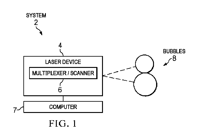
図1は、特定の実施形態による、気泡噴流を生成して眼浮遊物を治療する、例えば眼浮遊物を破砕し、且つ/又は眼から除去する眼科システム2の簡略化した例を示す。この例では、システム2は、図示のように結合されたレーザデバイス4、マルチプレクサ及び/又はスキャナ(マルチプレクサ/スキャナ)6及びコンピュータ7を含む。説明を容易にするために、眼の軸(例えば、光軸又は視軸)は、z軸に近似し、z軸は、z軸に実質的に直交する正面平面(例えば、xy平面)を規定する。正面パルスパターン(例えば、螺旋状又はラスタ正面パルスパターン)は、正面平面に形成されたパルスパターンである。
1. Exemplary System Figure 1 illustrates a simplified example of an
概要として、レーザデバイス4は、レーザパルスを含むレーザビームを発生させる。マルチプレクサ/スキャナ6は、レーザパルスを眼の硝子体に向けて誘導する。レーザパルスは、硝子体を光破壊するレーザ誘起光破壊(LIOB)を引き起こし、数回膨張及び収縮し得る急速に膨張(及び収縮)するキャビテーション気泡8を生成する。キャビテーション気泡8間の相互作用により、強力な水流である気泡噴流が生成される。気泡のエネルギー(内部高圧ガス及び表面張力のエネルギーなど)は、気泡噴流の運動エネルギーに変換される。気泡が異なるサイズを有する場合、気泡噴流の移動方向は、小さい気泡に向かう方向である。気泡噴流は、浮遊物を破砕し、視軸、すなわち外科医の視野から離れる方向に浮遊物破片を移動させる。
In summary, the
特定の実施形態では、気泡及び/又は気泡噴流は、浮遊物破片の除去を促進する。例えば、手術中に患者の頭部が直立位置にある場合、破片を視野から離れる方向に移動させるために、結果として生じる気泡噴流が後眼房の上部に向けて誘導されるようにキャビテーション気泡を方向付けることができる。別の例として、浮遊物の破砕後、残存する極めて小さい気泡が浮遊物破片に絡みつき、気泡の浮力によって破片が視野から離れる方向に持ち上げられる。別の例として、キャビテーション気泡が膨張及び崩壊を数回繰り返した後、キャビテーション気泡内の水蒸気が凝縮して水となり、一部のガス(例えば、H2、O2、CO2及びNOX)が気泡内に留まる。これらの気泡は、浮遊物破片と絡み合って、通常、約1分で破片を後眼房の最上部まで持ち上げる。数分後、気泡が硝子体に吸収されており、破片が視野から離れる方向に移動している。 In certain embodiments, the bubbles and/or bubble jets facilitate the removal of floater debris. For example, when the patient's head is in an upright position during surgery, the cavitation bubbles can be directed such that the resulting bubble jets are directed toward the top of the posterior chamber to move the debris away from the field of view. As another example, after the floater fragments, the remaining tiny bubbles become entangled with the floater debris, and the buoyancy of the bubbles lifts the debris away from the field of view. As another example, after the cavitation bubbles expand and collapse several times, the water vapor in the cavitation bubbles condenses into water, and some gases (e.g., H 2 , O 2 , CO 2 and NO x ) remain in the bubbles. These bubbles entangle with the floater debris and lift it to the top of the posterior chamber, usually in about one minute. After a few minutes, the bubbles are absorbed by the vitreous body, and the debris moves away from the field of view.
構成要素に着目すると、レーザデバイス4は、任意の適切な超短(例えば、ナノ秒、ピコ秒又はフェムト秒)パルスレーザデバイスを含み得る。レーザデバイス22の例としては、YAGレーザ(例えば、周波数2倍Qスイッチナノ秒YAGレーザなどのQスイッチナノ秒YAGレーザ)、ピコ秒レーザ(例えば、1~1.1ミクロン(μm)のスペクトル範囲で動作するモード同期ピコ秒レーザ又は第2高調波若しくは超短赤外線(700~1500ナノメートル(nm))ピコ秒レーザ)、フェムト秒レーザ(例えば、赤外線、超短赤外線(700~1500ナノメートル(nm))又は紫外線フェムト秒レーザ)及び単一パルスから高繰り返し率(10メガヘルツ(MHZ))のレーザが挙げられる。レーザビームは、任意の適切な波長(例えば、400~2000ナノメートル(nm))及び焦点(例えば、3~10ミクロン(μm)、例えば5~6ミクロン)を有し得る。パルスは、任意の適切な持続時間(例えば、20フェムト秒(fs)~1000ナノ秒(ns))、繰り返し率(例えば、25~100キロヘルツ(kHz)、例えば50kHz)及びパルスエネルギー(例えば、1マイクロジュール(μJ)~1ミリジュール(mJ)、例えば1~20μJ又は1~10μJ)を有し得る。
In terms of components, the
マルチプレクサ/スキャナ6は、マルチプレクサ及び/又はスキャナを含み得る。マルチプレクサは、レーザビームを分割して(又は他の方法で変調して)複数のレーザビームであって、各ビームが硝子体中にキャビテーション気泡を生成する複数のレーザビームを生じさせることができる任意の適切な光学デバイスを含む。一般に、光学デバイスは、光に作用(例えば、透過、反射、屈折、回折、コリメート、調整、整形、集束、変調及び/又は他の方法で作用)できる構成要素である。ビームマルチプレクサの例としては、回折光学素子(DOE)(回折格子など)、ホログラフィック光学素子(HOE)、空間光変調器(SLM)(例えば、電気的にアドレス可能なSLM)、偏光プリズム(例えば、ウォラストン、ノルマルスキー、ロション若しくはセナモントプリズム)、ビーム振幅分割型干渉計(例えば、マイケルソン、マッハツェンダ若しくはフィゾーウェッジ干渉計)、波面分割型干渉計(例えば、ロイドミラー若しくはフレネル複プリズム)、複屈折光学部品又は異なるビームマルチプレクサの組み合わせ(例えば、5倍回折マルチプレクサ及びウォラストン倍増器)が挙げられる。
The multiplexer/
スキャナは、硝子体中にキャビテーション気泡を生成するために、レーザビームの焦点を正面平面の異なる位置に移動させる。スキャナの例としては、ガルバノスキャナ(例えば、相互に垂直な軸の周りでチルトすることができるガルバノメトリック作動式スキャナミラーの対)、ビームを電気光学的に操作できる電気光学スキャナ(例えば、電気光学結晶スキャナ)又はビームを音響光学的に操作できる音響光学スキャナ(例えば、音響光学結晶スキャナ)を含み得る。 The scanner moves the focal point of the laser beam to different locations in the frontal plane to generate cavitation bubbles in the vitreous. Examples of scanners may include a galvanometer scanner (e.g., a pair of galvanometrically actuated scanner mirrors that can tilt about mutually perpendicular axes), an electro-optic scanner that can electro-optically steer the beam (e.g., an electro-optic crystal scanner), or an acousto-optic scanner that can acousto-optically steer the beam (e.g., an acousto-optic crystal scanner).
この例では、パルスは、任意の適切な数(例えば、2つ、3つ、4つ又はそれを超える)のキャビテーション気泡8を生成する。キャビテーション気泡8は、気泡8が互いに相互作用する(例えば、接触する)ことを可能にする任意の適切な空間的及び時間的距離を隔てて形成され得る。空間的なパルス間隔は、パルスエネルギーに応じて150マイクロメートル(μm)~2ミリメートル(mm)であり得る気泡の直径に応じて選択され得る。例えば、10マイクロジュール(μJ)のパルスは、150~300μmの直径を生じさせ得、6μJのパルスは、254μmの直径を生じさせ得、1mJのパルスは、1mmの直径を生じさせ得る。スキャナがキャビテーション気泡8を形成する場合、(時間的間隔を決定する)走査速度は、相互作用するのに十分に時間的に近接する気泡を生じさせるために気泡の寿命に応じて選択され得る。例えば、気泡の寿命は、約0.1~0.3ミリ秒(ms)であり得る。50キロヘルツ(kHz)の走査速度では、1/50kHz=20マイクロ秒(μs)毎に気泡が形成されるため、隣り合う気泡が相互作用するのに十分な長さまで膨張される。
In this example, the pulses generate any suitable number of cavitation bubbles 8 (e.g., 2, 3, 4 or more). The cavitation bubbles 8 may be formed at any suitable spatial and temporal distances that allow the
コンピュータ7は、コンピュータプログラムに従ってシステム2の構成要素を制御する。例えば、コンピュータ7は、気泡噴流を生成して浮遊物を破砕するか又は浮遊物破片を除去するために、レーザパルスを硝子体に集束させるようにレーザデバイス4及びマルチプレクサ/スキャナ6に命令する。
Computer 7 controls the components of
1.1 レーザ-細隙灯システム
図2A及び図2Bは、特定の実施形態による、キャビテーション気泡を生成して気泡噴流を形成できるビームマルチプレクサを備えた眼科レーザシステム10の一例を示す。図2Aは、ビームマルチプレクサを備えた眼科レーザシステム10の一例を示す。図2Bは、図2Aのシステム10で使用され得るビーム倍増器60を含むビームマルチプレクサの一例を示す。
1.1 Laser-Slit Lamp System Figures 2A and 2B show an example of an
この例では、眼科レーザシステム10は、術者が(術者の眼12を用いて)患者の眼14内の浮遊物を見ることを可能にする。眼科レーザシステム10は、図示のように結合された接眼レンズ20、レーザ送達ヘッド22、スリット照明源26、位置決めデバイス(ジョイスティック28など)、ベース30及びコンソール32を含む。レーザ送達ヘッド22は、図示のように結合されたレーザファイバ34、ズームシステム36、コリメータ38、ビームマルチプレクサ39、ミラー40及び対物レンズ42を含む。スリット照明源26は、図示のように結合された光源43、集光レンズ44、可変アパーチャ45、可変スリット板46、投影レンズ47及びミラー48を含む。コンソール32は、図示のように結合されたコンピュータ50、レーザ52及びユーザインターフェース54を含む。
In this example, the
概要として、眼科レーザシステム10は、レーザデバイス16(例えば、レーザ52、レーザファイバ34及びレーザ送達ヘッド22)と、細隙灯(例えば、接眼レンズ20、対物レンズ42、ミラー48及びスリット照明源26)を含む眼科顕微鏡18とを含む。術者の眼12は、接眼レンズ20からミラー40、対物レンズ42及びミラー48を通る光路を利用して、患者の眼14を視認する。レーザビームは、レーザ52からレーザ送達ヘッド22及びミラー48を通るレーザ経路を辿って患者の眼14を治療する。
In overview, the
概要によれば、レーザデバイス16は、レーザパルスを含むレーザビームを眼14内の浮遊物に向けて誘導する。眼科顕微鏡18は、眼14内から反射された光を集光して眼14の画像を生成する。レーザビームマルチプレクサ39は、硝子体中にキャビテーション気泡を形成するビームにレーザビームを多重化(例えば、分割又は他の方法で変調)し、図1を参照して説明したような任意の適切なマルチプレクサであり得る。コンピュータ50は、気泡噴流を生成するキャビテーション気泡を形成するためにレーザパルスを硝子体に向けて誘導するようにレーザデバイス16に命令する。
In summary, the laser device 16 directs a laser beam including laser pulses toward floaters in the
より詳細には、特定の実施形態では、接眼レンズ20は、術者の眼12が患者の眼14を視認することを可能にする。レーザ送達ヘッド22は、レーザ52からレーザファイバ34を通して患者の眼14にレーザパルスのレーザビームを送達する。レーザ52は、図1を参照して説明したような、レーザビームを発生させる任意の適切なレーザである。ズームシステム36は、ファイバ34から出射するレーザビームのスポットサイズを変化させる。コリメータ38は、レーザビームをコリメートし、ミラー40は、ビームを集束させる対物レンズ42を通してビームを誘導する。ズームシステム36及びコリメータ38は、平行レーザビームをミラー40に向けて誘導し、レーザビームを眼科顕微鏡18の像面に集束させる。ミラー40は、レーザビーム波長を反射し、可視光を透過するダイクロイックミラーであり得る。
More specifically, in certain embodiments, the
レーザシステム10のスリット照明源26は、患者の眼14の手術部位を照明する光を提供する。スリット照明源26は、高輝度照明光などの光を発する光源43を含む。集光レンズ44は、光を可変アパーチャ45及び可変スリット板46に向けて誘導する。可変アパーチャ45は、y方向における光の高さを規定し、可変スリット板43は、x方向における光の幅を規定して、光をスリット形状に成形する。投影レンズ47は、光をプリズムミラー48に向けて誘導し、プリズムミラー48は、スリット状の光を患者の眼14内に誘導する。
The
ベース30は、レーザ送達ヘッド22とスリット照明源26とを支持する。ジョイスティック28は、ベース30を移動させる。コンソール32は、システム10の動作をサポートする構成要素を含む。コンソール32のコンピュータ50は、システム10の構成要素、例えばベース30、レーザ送達ヘッド22、スリット照明源26、レーザ52及び/又はユーザインターフェース54の動作を制御する。ユーザインターフェース54は、術者とシステム10との間で情報の通信を行う。
The base 30 supports the
図2Bは、ビーム倍増器60を含むビームマルチプレクサの一例を示す。ビーム倍増器60は、レーザビームを複数のビームに分割し、複数のビームは、対物レンズ42に誘導される。対物レンズ42では、ビームは、異なる直径のキャビテーション気泡8(8a、8b)を生じさせる異なる強度I1、I2を有する。この例では、強度I1は、強度I2よりも大きく、気泡8bの直径よりも大きい直径を有する気泡8aを生じさせる。上で説明したように、気泡噴流の移動方向は、小さい気泡に向かう方向である。他の例では、キャビテーション気泡8は、実質的に同じ直径を有し得る。
Figure 2B shows an example of a beam multiplexer including a
この例では、ビーム倍増器60は、波長板62、例えば半波長板と、プリズム64、例えばウォラストンプリズムとを含む。波長板62は、それを通して進む光波の偏光状態を変える光学デバイスである。この例では、半波長板は、直線偏光の偏光方向を変化させる。プリズム64は、光を屈折させる平坦な表面を有する透明な光学デバイスである。少なくとも1つの表面は、別の表面に対して角度が付けられる(平行ではない)。ウォラストンプリズムは、光を直交する2つの直線偏光ビームに分離し、これらの直線偏光ビームは、2つの気泡を生じさせる。プリズム64は、任意の適切な気泡中心間隔、例えば0.1~3.0ミリメートル(mm)を有する気泡を生じさせるように、任意の適切な間隔、例えば0.2~5.0度を有し得る。例えば、2ミリジュール(mJ)のレーザパルスは、約1.8mmの直径を有する気泡を生じさせる。0.5度のプリズム間隔により、気泡が相互作用することを可能にするのに十分に近接する、160mm*sin(0.5)=1.4mmの気泡中心間隔がもたらされる。
In this example, the
気泡の強度比I1/I2(したがって気泡の相対直径)は、波長板62及び/又はプリズム64を調整すること、例えば回転させることによって変化させることができる。すなわち、波長板62は、異なる強度及び異なる直径を有するキャビテーション気泡を生成することができる。気泡噴流の方向は、小さい気泡に向かう方向であるため、波長板62は、気泡噴流の方向を調整するために使用され得る。
The intensity ratio I1 / I2 of the bubbles (and therefore the relative diameters of the bubbles) can be changed by adjusting, e.g., rotating, the
1.2 浮遊物検出-レーザシステム
図3は、特定の実施形態による、キャビテーション気泡を生成して気泡噴流を形成できるスキャナを備えた眼科レーザ手術システム110の一例を示す。概要として、システム110は、図示のように結合された浮遊物検出システム120、レーザデバイス122、1つ又は複数の共有構成要素124及びコンピュータ126を含む。レーザデバイス122は、図示のように結合されたレーザ130及びzスキャナ132を含む。共有構成要素124は、図示のように結合されたxyスキャナ140、xyエンコーダ141及び光学素子(ミラー142及びレンズ144、146など)を含む。コンピュータ126は、図示のように結合されたロジック150、メモリ152(コンピュータプログラム154を記憶する)及びディスプレイ156を含む。
1.2 Floater Detection - Laser System Figure 3 illustrates an example of an ophthalmic
システム110の動作の概要として、浮遊物検出システム120は、検出ビーム経路に沿って検出ビームを眼に向けて誘導し、浮遊物の位置を特定する。レーザデバイス122は、浮遊物検出システムから網膜に対する浮遊物のz位置を受信し、レーザビーム経路に沿ってレーザビームを浮遊物のz位置に向けて誘導する。共有構成要素のxyスキャナは、検出ビームを受信し、検出ビーム経路に沿って検出ビームを浮遊物に向けて誘導する。xyスキャナ140は、レーザデバイスからレーザビームも受信し、同じ検出ビーム経路に沿ってレーザビームを浮遊物に向けて誘導する。
As an overview of the operation of
システムの部分に着目すると、浮遊物検出システム120は、眼内の浮遊物を検出する1つ又は複数の検出デバイスを含む。浮遊物を検出するために、検出デバイスは、検出ビームを眼に向けて誘導し、眼から反射されたビームを検出し、反射されたビームを使用して浮遊物を検出する。デバイスは、浮遊物の存在を示すビームの変化を感知するか、又はディスプレイ156上に表示され得る、浮遊物若しくは網膜上の浮遊物の影(「浮遊物影」)の画像を生成することにより、反射されたビームから浮遊物を検出し得る。デバイスは、同じ又は異なる技術、例えば走査型レーザ検眼鏡(SLO)及び/又は光干渉断層撮影(OCT)を利用し得る。1つ又は複数の検出デバイスは、浮遊物のx、y及び/又はz位置を提供し得る。
Focusing on the system parts, the
レーザデバイス122は、レーザパルスを含むレーザビームを発生させるレーザ130を含む。レーザ130は、図1を参照して説明したような任意の適切なレーザ、例えばフェムト秒レーザを含み得る。zスキャナ132は、レーザビームの焦点を特定の位置へz方向に長手方向に誘導する。特定の実施形態では、レーザデバイス122は、気泡噴流を生成する複数のキャビテーション気泡を生じさせるためにレーザビームを多重化するマルチプレクサを含む。マルチプレクサは、図1を参照して説明したような任意の適切なマルチプレクサであり得る。
The
共有構成要素124は、検出ビーム及びレーザビームをそれぞれ浮遊物検出システム120及びレーザデバイス122から眼に向けて誘導する。検出ビーム及びレーザビームが両方とも共有構成要素124を使用するため、両方のビームは、同じ光学歪みの影響を受ける。したがって、レーザビームの照準を合わせるために検出ビームが使用される場合、歪みが相殺され、これによりレーザビームの精度が改善される。動作の一例として、ミラー142は、ビームをxyスキャナ140に向けて誘導し、xyスキャナ140は、レーザビームの焦点をレンズ144に向けてx及びy方向に横方向に誘導する。xyスキャナ140は、図1を参照して説明したような任意の適切なスキャナを含み得る。レンズ144及び146は、ビームを眼に向けて誘導する。xyエンコーダ141は、xyスキャナ140の位置を検出し、浮遊物検出システム120、レーザデバイス122及び/又はコンピュータ26に位置をエンコーダ単位で報告する。共有構成要素124は、ビームが同じ経路を共有することを可能にするために、検出ビーム及びレーザビームのスペクトル及び偏光結合及び分離も提供し得る。
The shared
コンピュータ126は、コンピュータプログラム154に従ってシステム110の構成要素を制御する。例えば、コンピュータ126は、構成要素(例えば、浮遊物検出システム120、レーザデバイス122及び共有構成要素124)を制御して、浮遊物を検出し、レーザビームを浮遊物に集束させる。コンピュータ126は、構成要素から分離され得るか、又は任意の適切な方式でシステム110間、例えば浮遊物検出システム120、レーザデバイス122及び/又は共有構成要素124内に分散して配置され得る。特定の実施形態では、浮遊物検出システム120、レーザデバイス122及び/又は共有構成要素124を制御するコンピュータ126の部分は、それぞれ浮遊物検出システム120、レーザデバイス122及び/又は共有構成要素124の一部であり得る。
The
2.浮遊物
図4は、浮遊物210を跳び上がらせるレーザパルスの一例を示す。パルスが浮遊物210の中心に当たると、気泡が浮遊物210を破砕する。しかしながら、パルスが浮遊物210の周辺に当たると、気泡が浮遊物210を急速に押し、浮遊物210を跳び上がらせる。浮遊物210が例えば1ミリメートル(mm)の距離だけ跳び上がる場合、位置決めデバイスを用いてレーザの方向を変えなければならない。
2. Suspended Objects Figure 4 shows an example of a laser pulse that causes the suspended object 210 to jump up. If the pulse hits the center of the suspended object 210, the air bubbles will break up the suspended object 210. However, if the pulse hits the periphery of the suspended object 210, the air bubbles will push the suspended object 210 rapidly, causing it to jump up. If the suspended object 210 jumps up by a distance of, for example, 1 millimeter (mm), the laser must be redirected using a positioning device.
特定の実施形態では、システム2は、浮遊物を跳び上がらせる可能性を低減するレーザパルスパターンを作成し得る。このパターンは、浮遊物210の動きを抑制するために、浮遊物210が跳び上がる可能性がある経路(例えば、浮遊物210の領域の外側)にパルスを配置する。すなわち、パルスパターンの適用範囲(すなわちパルスパターンの最も外側のパルスで囲まれた領域)は、浮遊物210の重心の周りに実質的に中心が位置し得、浮遊物210の少なくとも大部分よりも大きいことがある。
In certain embodiments,
3.気泡噴流
図5は、図2A、図2B及び図3の眼科レーザシステム10及び110によって生成され得る気泡噴流9の一例を示す。この例では、眼科レーザシステム10は、気泡噴流9を生成するキャビテーション気泡8を形成する。例えば、ビームマルチプレクサを備えた低繰り返し率(例えば、毎秒3パルス(pps)未満)のレーザデバイスが気泡噴流9を形成し得る。キャビテーション気泡8は、大きい気泡8a及び小さい気泡8bを含む。気泡噴流9の移動方向は、小さい気泡8bに向かう方向である。方向は、大きい気泡8aから小さい気泡8bに向かって気泡8の中心を通るように引かれた線によって決定され得る。
3. Bubble Jet FIG. 5 shows an example of a
図6は、図2A、図2B及び図3の眼科レーザシステム10及び110によって生成され得る気泡噴流9の一例を示す。この例では、眼科レーザシステム10は、スキャナが走査する場所を示す走査線11に沿ってキャビテーション気泡8(8a、8b)を生成する。気泡8bは、気泡8が合体できる距離をおいて気泡8aの後ろに生成される。キャビテーション気泡8は、相互作用して、走査線11の軌跡に対して接線方向に伝搬する気泡噴流9を生成する。
Figure 6 shows an example of a
図7A及び図7Bは、異なる直径のキャビテーション気泡220(220a、220b)から生じる気泡噴流224の例を示し、気泡220aは気泡220bよりも大きい。キャビテーション気泡220(220a、220b)は、気泡220が相互作用することを可能にする任意の適切な距離を隔てて、例えば5~20ミクロン、例えば約10ミクロン隔てて形成され得る。キャビテーション気泡220a及び220b間の相互作用により、小さい気泡220bに向かって流れる気泡噴流224が形成される。
7A and 7B show an example of a
4.パルスパターン
図8及び図9は、図1のシステム10によって生成され得る正面パルスパターン230(230a及び230b)の例を示す。パルスパターン230は、浮遊物を破砕し、且つ/又は浮遊物破片を除去する気泡噴流を生成する。この例では、パルスパターン230は、パルス群を含み、各パルス群は、気泡噴流を生成するために互いに近接するキャビテーション気泡を有する気泡群222を生じさせる。パルスパターン230は、2次元又は3次元の任意の適切なサイズ又は形状を有し得、気泡群222は、任意の適切な数の気泡を有し得る。特定の実施形態では、パターン230の正面適用範囲は、浮遊物の正面寸法をカバーし得る。特定の場合(例えば、厚みのある浮遊物について)、複数の正面パターン230が、異なる深さに適用され得、3次元パターン230が得られる。
4. Pulse Patterns Figures 8 and 9 show examples of frontal pulse patterns 230 (230a and 230b) that can be generated by the
パルスパターン230は、任意の適切な方式で形成され得る。例えば、ビームマルチプレクサを伴う中程度の繰り返し率(例えば、100Hz~10kHz)のピコ秒又はフェムト秒レーザは、パルスパターン230を生成することができる。この例では、1スポット当たりのレーザパルスエネルギーは、20μJであり、対応する気泡振動周期は、T=13.3μs*201/3=36.1μsである。100~10kHzの繰り返し率は、100~10,000μsのパルス間隔に対応する。この例では、先の気泡群222は、次のパルス群が到達する前に消滅するため、パルス群と先の気泡群222の残りとの間に相互作用が生じない。
The pulse pattern 230 may be formed in any suitable manner. For example, a picosecond or femtosecond laser with a moderate repetition rate (e.g., 100 Hz-10 kHz) with a beam multiplexer can generate the pulse pattern 230. In this example, the laser pulse energy per spot is 20 μJ, and the corresponding bubble oscillation period is T=13.3 μs*20 1/3 =36.1 μs. A repetition rate of 100-10 kHz corresponds to a pulse interval of 100-10,000 μs. In this example, the
別の例として、ビームマルチプレクサを伴う高繰り返し率(例えば、40~150kHz)のピコ秒又はフェムト秒レーザは、パルスパターン230を作成することができる。この例では、パルスエネルギーは、1スポット当たり20μJであり、繰り返し率は、40kHzであり、パルス間隔時間は、25μsである。したがって、次のパルス群は、先の気泡群222(又は跳ね返った気泡)が依然として存在している(又は生存している若しくは生きている)ときに到達する。これらの条件下では、異なる気泡群222が相互作用して、複数群の相互作用を生じさせ、例えば、2つの気泡の2つの群は、4回の気泡相互作用を生じさせる。複数群の相互作用により、浮遊物を破砕し、且つ/又は浮遊物破片を除去するために気泡噴流が生成される。
As another example, a picosecond or femtosecond laser with a high repetition rate (e.g., 40-150 kHz) with a beam multiplexer can create the pulse pattern 230. In this example, the pulse energy is 20 μJ per spot, the repetition rate is 40 kHz, and the pulse interval time is 25 μs. Thus, the next pulse group arrives when the previous bubble group 222 (or the rebounded bubbles) are still present (or alive or live). Under these conditions,
別の例として、高繰り返し率(例えば、40~150kHz)のレーザは、パルスパターン230を作成する。この例では、パルスパターンは、視野の中心から開始して浮遊物を破砕し、浮遊物破片を視野から離れる方向に移動させる螺旋状走査である。その螺旋は、大きい(例えば、50μmの)接線方向スポット間隔を有し、1スポット当たりのレーザパルスエネルギーは、20μJであり、対応する気泡振動周期は、T=13.3μs*201/3=36.1μsである。40~150kHzの繰り返し率は、6.67~25μsのパルス間隔に対応する。したがって、次のパルスは、先のキャビテーション気泡が依然として存在して気泡噴流を形成しているときに到達する。噴流の方向は、螺旋に対して接線方向であり、噴流の長さは、数ミリメートル程の長さであり得る。 As another example, a high repetition rate (e.g., 40-150 kHz) laser creates a pulse pattern 230. In this example, the pulse pattern is a spiral scan that starts at the center of the field of view, breaks up the floaters, and moves the floaters debris away from the field of view. The spiral has a large (e.g., 50 μm) tangential spot spacing, the laser pulse energy per spot is 20 μJ, and the corresponding bubble oscillation period is T=13.3 μs*20 1/3 =36.1 μs. A repetition rate of 40-150 kHz corresponds to a pulse spacing of 6.67-25 μs. Thus, the next pulse arrives when the previous cavitation bubble is still present and forming a bubble jet. The direction of the jet is tangential to the spiral, and the length of the jet can be as long as several millimeters.
4.1 螺旋状パルスパターン
図8は、螺旋状パルスパターン230aの一例を示す。螺旋状パルスパターン230aは、気泡群222を生じさせる螺旋状パターンのパルス群を含み、各気泡群222は、気泡噴流224を生じさせるように設計される。この例では、気泡噴流224の運動エネルギーを最適化するために、同じ方向を向いた噴流で気泡噴流224が生成される。螺旋状パルスパターン230aは、任意の適切な数のパルス(例えば、10~1000パルス)、接線方向スポット間隔(例えば、2~100μm)及び径方向スポット間隔(例えば、2~200μm)で作成され得る。
4.1 Spiral Pulse Pattern Figure 8 shows an example of a
4.2 ラスタパルスパターン
図9は、ラスタパルスパターン230bの一例を示す。ラスタパルスパターン230bは、気泡群222を生じさせるパルス群のラスタパターンを含み、各気泡群222は、気泡噴流224を生じさせるように設計される。この例では、気泡噴流224の運動エネルギーを最適化するために、同じ方向を向いた噴流で気泡噴流224が生成される。ラスタパターンは、一方向に走査してパルスの行を形成し、行の端で向きを変え、次に先の行に近接する反対方向に走査してパルスの次の行を形成することによって形成される。ラスタパルスパターン230bは、任意の適切な数のパルス(例えば、10~1000パルス)、同じ行内のスポット間隔(例えば、2~100μm)及び行間隔(例えば、2~200μm)で作成され得る。
4.2 Raster Pulse Pattern FIG. 9 shows an example of a raster pulse pattern 230b. The raster pulse pattern 230b includes a raster pattern of pulses that create
5.例示的な方法
図10は、図1のシステム10によって実行され得る、気泡噴流を生成して浮遊物を破砕する方法の一例を示す。方法は、ステップ310で始まり、ステップ310では、コンピュータは、浮遊物を破砕するようにレーザデバイスに命令する。レーザデバイスは、ステップ312でレーザビームを発生させる。レーザビームは、フェムト秒パルスなどのレーザパルスを含み得る。レーザビームは、ステップ314で多重化及び/又は走査されて、硝子体中に複数のキャビテーション気泡を生成する。
5. Exemplary Methods Figure 10 illustrates an example of a method for generating a bubble jet to break up floaters that may be performed by the
レーザパルスは、ステップ316でキャビテーション気泡を形成して気泡噴流を生成する。気泡は、異なる(又は同じ)直径を有し得る。特定の実施形態では、キャビテーション気泡は、気泡噴流を特定の方向、例えばより小さい気泡の方向に誘導するように配置される。キャビテーション気泡は、ステップ318で気泡噴流を生成して浮遊物を破砕する。
The laser pulses form cavitation bubbles to generate a bubble jet in
図11は、図1のシステム10によって実行され得る、気泡噴流を生成して浮遊物破片を除去する方法の一例を示す。方法は、ステップ410で始まり、ステップ410では、コンピュータは、レーザデバイスのパルスパターンにアクセスする。パルスパターンは、浮遊物破片の除去の方向を制御するように設計され得る。コンピュータは、ステップ412において、パルスパターンに従い、レーザパルスを浮遊物に向けて誘導するようにレーザデバイスに命令する。
Figure 11 illustrates an example method for generating a bubble jet to remove floating debris that may be performed by the
パルスは、ステップ414でキャビテーション気泡を形成する。特定の実施形態では、キャビテーション気泡は、破片の除去を促進する1つ又は複数の方向に向いた気泡噴流を生成するように配置される。キャビテーション気泡は、ステップ420で気泡噴流を生成して浮遊物破片を除去する。気泡噴流の力は、破片を視軸から離れる方向に移動させる。加えて、いくつかの気泡が崩壊した後、より長寿命の気泡が破片に絡まって、破片を視軸から離れる方向に移動させる。
The pulses form cavitation bubbles at
本明細書に開示のシステム及び装置の構成要素(制御コンピュータなど)は、インターフェース、ロジック及び/又はメモリを含み得、これらの任意のものは、コンピュータハードウェア及び/又はソフトウェアを含み得る。インターフェースは、構成要素への入力を受信し、且つ/又は構成要素からの出力を送信することができ、通常、ソフトウェア、ハードウェア、周辺機器、ユーザ及びこれらの組み合わせなどの間で情報を交換するために使用される。ユーザインターフェースは、コンピュータと通信する(例えば、コンピュータに入力を送信し、且つ/又はコンピュータから出力を受信する)ためにユーザが利用できるインターフェースの一種である。ユーザインターフェースの例としては、ディスプレイ、グラフィカルユーザインターフェース(GUI)、タッチスクリーン、キーボード、マウス、ジェスチャセンサ、マイク及びスピーカが挙げられる。 Components of the systems and devices disclosed herein (such as a control computer) may include interfaces, logic, and/or memory, any of which may include computer hardware and/or software. An interface may receive input to and/or send output from a component, and is typically used to exchange information between software, hardware, peripherals, users, combinations thereof, and the like. A user interface is a type of interface that a user can use to communicate with a computer (e.g., send input to and/or receive output from a computer). Examples of user interfaces include a display, a graphical user interface (GUI), a touch screen, a keyboard, a mouse, a gesture sensor, a microphone, and a speaker.
ロジックは、構成要素の操作を行うことができる。ロジックは、データを処理する、例えば命令を実行して入力から出力を生成する1つ又は複数の電子デバイスを含み得る。かかる電子デバイスの例としては、コンピュータ、プロセッサ、マイクロプロセッサ(例えば中央処理装置(CPU))及びコンピュータチップが挙げられる。ロジックは、操作を行うために電子デバイスによって実行され得る命令を符号化するコンピュータソフトウェアを含み得る。コンピュータソフトウェアの例としては、コンピュータプログラム、アプリケーション及びオペレーティングシステムが挙げられる。 Logic may perform operations on components. Logic may include one or more electronic devices that process data, e.g., execute instructions to generate output from input. Examples of such electronic devices include computers, processors, microprocessors (e.g., central processing units (CPUs)), and computer chips. Logic may include computer software that encodes instructions that can be executed by the electronic devices to perform operations. Examples of computer software include computer programs, applications, and operating systems.
メモリは、情報を記憶することができ、有形のコンピュータ可読及び/又はコンピュータ実行可能なストレージ媒体を含み得る。メモリの例としては、コンピュータメモリ(例えば、ランダムアクセスメモリ(RAM)又は読み出し専用メモリ(ROM))、マスストレージメディア(例えば、ハードディスク)、リムーバブルストレージメディア(例えば、コンパクトディスク(CD)又はデジタルビデオ若しくは多用途ディスク(DVD))、データベース、ネットワークストレージ(例えば、サーバ)及び/又は他のコンピュータ可読媒体が挙げられる。特定の実施形態は、コンピュータソフトウェアを用いて符号化されたメモリを対象とし得る。 A memory may store information and may include tangible computer-readable and/or computer-executable storage media. Examples of memory include computer memory (e.g., random access memory (RAM) or read-only memory (ROM)), mass storage media (e.g., hard disks), removable storage media (e.g., compact discs (CDs) or digital video or versatile discs (DVDs)), databases, network storage (e.g., servers), and/or other computer-readable media. Certain embodiments may be directed to memory encoded with computer software.
特定の実施形態に関して本開示を説明したが、実施形態の修正形態(例えば、変更形態、置換形態、追加形態、省略形態及び/又は他の修正形態)が当業者に明らかになるであろう。したがって、本発明の範囲から逸脱することなく、実施形態に対する修正形態がなされ得る。例えば、本明細書で開示されたシステム及び装置に対する修正形態がなされ得る。当業者に明らかであるように、システム及び装置の構成要素は、統合若しくは分離され得るか、又はシステム及び装置の動作は、より多い、より少ない若しくは他の構成要素によって実行され得る。別の例として、本明細書で開示された方法に対する修正形態がなされ得る。当業者に明らかであるように、方法は、より多い、より少ない又は他のステップを含み得、ステップは、任意の適切な順序で実行され得る。 While the present disclosure has been described with respect to certain embodiments, modifications of the embodiments (e.g., changes, substitutions, additions, omissions, and/or other modifications) will be apparent to those of ordinary skill in the art. Thus, modifications may be made to the embodiments without departing from the scope of the present invention. For example, modifications may be made to the systems and devices disclosed herein. As would be apparent to one of ordinary skill in the art, components of the systems and devices may be integrated or separated, or operations of the systems and devices may be performed by more, fewer, or other components. As another example, modifications may be made to the methods disclosed herein. As would be apparent to one of ordinary skill in the art, the methods may include more, fewer, or other steps, and the steps may be performed in any suitable order.
請求項を解釈する際に特許庁及び読者を補助するために、本出願人らは、用語「~するための手段」又は「~するためのステップ」が特定の請求項で明示的に使用されない限り、請求項又は請求要素のいかなるものも合衆国法典第35巻§112条(f)を想起させるように意図されないことを注記する。請求項内の任意の他の用語(例えば、「機構」、「モジュール」、「デバイス」、「ユニット」、「構成要素」、「要素」、「部材」、「装置」、「機械」、「システム」、「プロセッサ」又は「コントローラ」)の使用は、当業者に既知の構造を指すものと本出願人らによって理解され、したがって合衆国法典第35巻§112条(f)を想起させるように意図されない。 To assist the Patent Office and the reader in interpreting the claims, applicants note that no claim or claim element is intended to invoke 35 U.S.C. §112(f) unless the terms "means for" or "step for" are expressly used in a particular claim. Use of any other terminology in the claims (e.g., "mechanism," "module," "device," "unit," "component," "element," "member," "apparatus," "machine," "system," "processor," or "controller") is understood by applicants to refer to structures known to those of skill in the art and is therefore not intended to invoke 35 U.S.C. §112(f).
Claims (10)
複数のレーザパルスを前記眼の前記硝子体中の前記浮遊物に向けて誘導するように構成されたレーザデバイスと、
前記硝子体中の前記浮遊物を検出するように構成された浮遊物検出システムと、
コンピュータであって、
前記複数のレーザパルスのパルスパターンであって、前記眼の前記硝子体中に気泡噴流を生成する複数のキャビテーション気泡を生じさせるパルスパターンにアクセスすることと、
前記気泡噴流を生成して前記浮遊物を治療するために、前記パルスパターンに従って前記複数のレーザパルスを前記浮遊物に向けて誘導するように前記レーザデバイスに命令することと
を行うように構成されたコンピュータと
を含む眼科レーザシステム。 1. An ophthalmic laser system for treating floaters in the vitreous of an eye, comprising:
a laser device configured to direct a plurality of laser pulses toward the floaters in the vitreous of the eye;
a floater detection system configured to detect the floaters in the vitreous;
A computer comprising:
accessing a pulse pattern of the plurality of laser pulses that produces a plurality of cavitation bubbles that generate a bubble jet in the vitreous of the eye;
and instructing the laser device to direct the plurality of laser pulses toward the floaters according to the pulse pattern to generate the bubble jet to treat the floaters.
第1の直径を有する第1のキャビテーション気泡を生成することと、
前記第1の直径と異なる第2の直径を有する第2のキャビテーション気泡を生成することと
を行うように前記レーザデバイスに命令することにより、前記複数のレーザパルスを前記浮遊物に向けて誘導するように前記レーザデバイスに命令するように構成される、請求項1に記載の眼科レーザシステム。 The computer includes:
generating a first cavitation bubble having a first diameter;
2. The ophthalmic laser system of claim 1, further configured to instruct the laser device to direct the plurality of laser pulses toward the floater by instructing the laser device to generate a second cavitation bubble having a second diameter different from the first diameter.
レーザビームを発生させるように構成されたレーザと、
前記複数のキャビテーション気泡を形成して前記気泡噴流を生成する前記複数のレーザパルスに前記レーザビームを分割するように構成されたビームマルチプレクサと
を含む、請求項1に記載の眼科レーザシステム。 The laser device comprises:
a laser configured to generate a laser beam;
2. The ophthalmic laser system of claim 1, further comprising: a beam multiplexer configured to split the laser beam into the plurality of laser pulses that form the plurality of cavitation bubbles to generate the bubble jet.
前記レーザデバイスから前記レーザパルスを受信し、且つ前記レーザパルスを前記検出ビーム経路に沿って前記浮遊物影に向けて誘導することと
を行うように構成されたxyスキャナを更に含む、請求項1に記載の眼科レーザシステム。 receiving a detection beam from the floater detection system and directing the detection beam along a detection beam path toward a floater shadow cast by the floater on a retina of the eye;
2. The ophthalmic laser system of claim 1, further comprising an xy scanner configured to receive the laser pulses from the laser device and direct the laser pulses along the detection beam path toward the floating object.
Applications Claiming Priority (3)
| Application Number | Priority Date | Filing Date | Title |
|---|---|---|---|
| US202163281326P | 2021-11-19 | 2021-11-19 | |
| US63/281,326 | 2021-11-19 | ||
| PCT/IB2022/060212 WO2023089414A1 (en) | 2021-11-19 | 2022-10-24 | Generating bubble jets to fragment and remove eye floaters |
Publications (1)
| Publication Number | Publication Date |
|---|---|
| JP2024538244A true JP2024538244A (en) | 2024-10-18 |
Family
ID=84329505
Family Applications (1)
| Application Number | Title | Priority Date | Filing Date |
|---|---|---|---|
| JP2024524633A Pending JP2024538244A (en) | 2021-11-19 | 2022-10-24 | Generating a bubble jet to break up and remove eye floaters |
Country Status (7)
| Country | Link |
|---|---|
| US (1) | US12502314B2 (en) |
| EP (1) | EP4432999A1 (en) |
| JP (1) | JP2024538244A (en) |
| CN (1) | CN118201574A (en) |
| AU (1) | AU2022394108A1 (en) |
| CA (1) | CA3234889A1 (en) |
| WO (1) | WO2023089414A1 (en) |
Families Citing this family (1)
| Publication number | Priority date | Publication date | Assignee | Title |
|---|---|---|---|---|
| WO2025057046A1 (en) * | 2023-09-15 | 2025-03-20 | Alcon Inc. | Polarization sensitive optical coherence tomography for visualization of vitreous opacities |
Family Cites Families (154)
| Publication number | Priority date | Publication date | Assignee | Title |
|---|---|---|---|---|
| US3780979A (en) | 1972-05-12 | 1973-12-25 | Clinitex Inc | Adjustable fundus illumination |
| US4357088A (en) | 1981-03-02 | 1982-11-02 | The United States Of America As Represented By The Department Of Health And Human Services | Macula-disc camera with improved resolution |
| US5312396A (en) | 1990-09-06 | 1994-05-17 | Massachusetts Institute Of Technology | Pulsed laser system for the surgical removal of tissue |
| US6322556B1 (en) | 1991-10-30 | 2001-11-27 | Arlene E. Gwon | Method of laser photoablation of lenticular tissue for the correction of vision problems |
| US5782822A (en) | 1995-10-27 | 1998-07-21 | Ir Vision, Inc. | Method and apparatus for removing corneal tissue with infrared laser radiation |
| EP0921764A1 (en) | 1996-05-10 | 1999-06-16 | California Institute Of Technology | Conoscopic system for real-time corneal topography |
| US6789900B2 (en) | 1996-11-22 | 2004-09-14 | Jozef F. Van De Velde | Scanning laser ophthalmoscope optimized for selective retinal microphotocoagulation |
| DE19705044A1 (en) | 1997-02-03 | 1998-08-06 | Joachim Buerger | Method for measuring profile depth of profiled bodies |
| US6142630A (en) | 1998-05-08 | 2000-11-07 | Koester; Charles J. | Variable focus lens system such as for examination or treatment of transparent or semi-transparent materials such as ocular tissue |
| WO1999058047A1 (en) | 1998-05-09 | 1999-11-18 | Velde Frans J Van De | Scanning laser ophthalmoscope for microphotocoagulation with minimal optical aberrations |
| DE19940712A1 (en) | 1999-08-26 | 2001-03-01 | Aesculap Meditec Gmbh | Method and device for treating opacities and / or hardening of an unopened eye |
| US7374287B2 (en) | 1999-11-01 | 2008-05-20 | Jozef F. Van de Velde | Relaxed confocal catadioptric scanning laser ophthalmoscope |
| IL133073A (en) | 1999-11-22 | 2003-06-24 | Yaakov Amitai | Method and system for treating a target plane with a laser beam |
| US6361167B1 (en) | 2000-06-13 | 2002-03-26 | Massie Research Laboratories, Inc. | Digital eye camera |
| US6932914B2 (en) * | 2002-01-18 | 2005-08-23 | Leclair Mark L. | Method and apparatus for the controlled formation of cavitation bubbles using target bubbles |
| US20040004055A1 (en) * | 2002-01-18 | 2004-01-08 | Barros Emanuel F. | Method and apparatus for the controlled formation of cavitation bubbles |
| AU2002951467A0 (en) | 2002-09-18 | 2002-10-03 | Ellex Medical Pty Ltd | Ophthalmic laser |
| US7131727B2 (en) | 2003-06-30 | 2006-11-07 | Johnson & Johnson Vision Care, Inc. | Simultaneous vision emulation for fitting of corrective multifocal contact lenses |
| US7425067B2 (en) | 2003-11-14 | 2008-09-16 | Ophthonix, Inc. | Ophthalmic diagnostic instrument |
| JP4531413B2 (en) | 2004-02-10 | 2010-08-25 | 株式会社トプコン | Slit lamp microscope |
| WO2005117534A2 (en) | 2004-05-29 | 2005-12-15 | The General Hospital Corporation | Process, system and software arrangement for a chromatic dispersion compensation using reflective layers in optical coherence tomography (oct) imaging |
| US8394084B2 (en) | 2005-01-10 | 2013-03-12 | Optimedica Corporation | Apparatus for patterned plasma-mediated laser trephination of the lens capsule and three dimensional phaco-segmentation |
| US7382464B2 (en) | 2005-01-20 | 2008-06-03 | Carl Zeiss Meditec, Inc. | Apparatus and method for combined optical-coherence-tomographic and confocal detection |
| JP4879897B2 (en) | 2005-05-10 | 2012-02-22 | 卓也 片岡 | Ophthalmic laser therapy device |
| US7703922B2 (en) | 2005-07-15 | 2010-04-27 | Jozef F Van de Velde | Relaxed confocal catadioptric scanning laser ophthalmoscope |
| WO2007041125A1 (en) | 2005-09-29 | 2007-04-12 | Bioptigen, Inc. | Portable optical coherence tomography devices and related systems |
| US20070121069A1 (en) | 2005-11-16 | 2007-05-31 | Andersen Dan E | Multiple spot photomedical treatment using a laser indirect ophthalmoscope |
| WO2007127395A2 (en) | 2006-04-28 | 2007-11-08 | Bioptigen, Inc. | Methods, systems and computer program products for optical coherence tomography (oct) using automatic dispersion compensation |
| US20070291277A1 (en) | 2006-06-20 | 2007-12-20 | Everett Matthew J | Spectral domain optical coherence tomography system |
| JP4822969B2 (en) | 2006-07-27 | 2011-11-24 | 株式会社ニデック | Ophthalmic imaging equipment |
| US20080114386A1 (en) * | 2006-11-09 | 2008-05-15 | Bernardino Iliakis | Method of providing corneal tissue and method of determining the bioburden of laboratory providing same |
| US8652602B1 (en) | 2007-02-28 | 2014-02-18 | William Jacob Spenner Dolla | Rotational expansion auxetic structures |
| JP2008220770A (en) | 2007-03-14 | 2008-09-25 | Topcon Corp | Wavefront aberration correction apparatus |
| SI22525A (en) | 2007-05-05 | 2008-12-31 | OPTOTEK@d.o.o. | Module with white light diode for simple replacement of the bulb module inside a permanent slot light |
| US8101921B2 (en) * | 2007-06-04 | 2012-01-24 | Carl Zeiss Sms Ltd | Apparatus and method for inducing controllable jets in liquids |
| JP5623907B2 (en) | 2007-09-05 | 2014-11-12 | アルコン レンゼックス, インコーポレーテッド | Laser-induced protective shield in laser surgery |
| US9456925B2 (en) * | 2007-09-06 | 2016-10-04 | Alcon Lensx, Inc. | Photodisruptive laser treatment of the crystalline lens |
| DE112008002448B4 (en) | 2007-09-10 | 2013-03-21 | Alcon Lensx, Inc. | Effective laser photodisruptive surgery in a gravitational field |
| WO2009039315A2 (en) | 2007-09-18 | 2009-03-26 | Lensx Lasers, Inc. | Methods and apparatus for laser treatment of the crystalline lens |
| CN101951829B (en) | 2007-11-05 | 2013-11-20 | Opko仪器公司 | A method for performing visual acuity testing |
| DE102008000225B3 (en) | 2008-02-01 | 2009-03-26 | Linos Photonics Gmbh & Co. Kg | fundus |
| US8480659B2 (en) | 2008-07-25 | 2013-07-09 | Lensar, Inc. | Method and system for removal and replacement of lens material from the lens of an eye |
| US8550624B2 (en) | 2008-11-06 | 2013-10-08 | Wavetec Vision Systems, Inc. | Optical angular measurement system for ophthalmic applications and method for positioning of a toric intraocular lens with increased accuracy |
| US7988293B2 (en) | 2008-11-14 | 2011-08-02 | AMO Wavefront Sciences LLC. | Method of qualifying light spots for optical measurements and measurement instrument employing method of qualifying light spots |
| WO2010117386A1 (en) | 2009-04-10 | 2010-10-14 | Doheny Eye Institute | Ophthalmic testing methods, devices and systems |
| US8740383B2 (en) | 2009-05-06 | 2014-06-03 | University Of Virginia Patent Foundation | Self-illuminated handheld lens for retinal examination and photography and related method thereof |
| US8262647B2 (en) | 2009-07-29 | 2012-09-11 | Alcon Lensx, Inc. | Optical system for ophthalmic surgical laser |
| US20110077514A1 (en) | 2009-09-29 | 2011-03-31 | Medicis Technologies Corporation | Variable treatment site body contouring using an ultrasound therapy device |
| CA2787336A1 (en) | 2010-01-21 | 2011-07-28 | Physical Sciences, Inc. | Multi-functional adaptive optics retinal imaging |
| DE112011101866A5 (en) | 2010-06-03 | 2013-03-14 | Carl Zeiss Meditec Ag | Device and method for vitreous surgery |
| US8851679B2 (en) | 2010-06-14 | 2014-10-07 | Frans J. Van de Velde | Electronic ophthalmoscope for selective retinal photodisruption of the photoreceptor mosaic |
| US20160074221A1 (en) | 2010-06-14 | 2016-03-17 | Marie-Jose B. Tassignon | Femtosecond laser apparatus for plasma induced vitreous ablation in the eye |
| JP5685013B2 (en) | 2010-06-30 | 2015-03-18 | キヤノン株式会社 | Optical tomographic imaging apparatus, control method therefor, and program |
| JP5693101B2 (en) | 2010-08-30 | 2015-04-01 | キヤノン株式会社 | Image processing apparatus and image processing method |
| JP5842330B2 (en) | 2010-12-27 | 2016-01-13 | 株式会社ニデック | Fundus photocoagulation laser device |
| WO2012135073A2 (en) | 2011-03-25 | 2012-10-04 | Board Of Trustees Of Michigan State University | Adaptive laser system for ophthalmic use |
| JP5690193B2 (en) | 2011-04-18 | 2015-03-25 | 株式会社ニデック | Optical tomography system |
| JP5767014B2 (en) | 2011-05-07 | 2015-08-19 | 株式会社ニデック | Ophthalmic observation system and image processing method |
| CA3133258A1 (en) | 2011-06-23 | 2012-12-27 | Amo Development, Llc | Ophthalmic range finding |
| DE102011109058A1 (en) | 2011-07-29 | 2013-01-31 | Carl Zeiss Meditec Ag | "Ophthalmic Laser Device and Method for the Prevention and Treatment of After-Star" |
| US9033497B2 (en) | 2011-12-29 | 2015-05-19 | Elwha Llc | Optical device with interchangeable corrective elements |
| US9381116B2 (en) | 2012-05-25 | 2016-07-05 | Ojai Retinal Technology, Llc | Subthreshold micropulse laser prophylactic treatment for chronic progressive retinal diseases |
| CN104487029B (en) | 2012-08-28 | 2017-04-05 | 视乐有限公司 | For reducing the scan method and system of opaque bubble layer |
| GB201217538D0 (en) | 2012-10-01 | 2012-11-14 | Optos Plc | Improvements in or relating to scanning laser ophthalmoscopes |
| US10285860B2 (en) | 2012-11-02 | 2019-05-14 | Optimedica Corporation | Vacuum loss detection during laser eye surgery |
| US8783868B2 (en) | 2012-12-21 | 2014-07-22 | Carl Zeiss Meditec, Inc. | Two-dimensional confocal imaging using OCT light source and scan optics |
| US10335315B2 (en) | 2013-02-01 | 2019-07-02 | Alcon Lensx, Inc. | Bi-radial patient interface |
| US20140257257A1 (en) | 2013-03-11 | 2014-09-11 | Robert Edward Grant | Systems and methods for treating target tissue in the vitreous cavity |
| CA2906552A1 (en) | 2013-03-13 | 2014-10-02 | Riverside Research Institute | Methods for diagnosing vitreo-retinal disease |
| EP3900684A1 (en) | 2013-03-15 | 2021-10-27 | AMO Development, LLC | System and method for ophthalmic laser surgery employing eye tracking without eye docking |
| CA2940307C (en) | 2014-02-28 | 2022-07-12 | Excel-Lens, Inc. | Laser assisted cataract surgery |
| US10441465B2 (en) | 2014-03-26 | 2019-10-15 | Optimedica Corporation | Registration of LOI fiducials with camera |
| US10159602B2 (en) * | 2014-05-07 | 2018-12-25 | Wavelight Gmbh | Technique for photodisruptive multi-pulse treatment of a material |
| WO2015171793A1 (en) | 2014-05-07 | 2015-11-12 | Ryan Edwin | Device and method to quantify vitreous opacity impairment |
| JP6410468B2 (en) | 2014-05-22 | 2018-10-24 | 株式会社トプコン | Ophthalmic equipment |
| CA2893494C (en) * | 2014-05-28 | 2022-11-01 | Institut National D'optique | Laser-directed microcavitation |
| US20150342782A1 (en) | 2014-05-30 | 2015-12-03 | Strathspey Crown Holdings, LLC | Treatment Systems for Vitreous Floaters |
| JP2017526507A (en) | 2014-08-31 | 2017-09-14 | ベレシュトカ,ジョン | System and method for analyzing eyes |
| JP6458467B2 (en) | 2014-12-01 | 2019-01-30 | 株式会社ニデック | Ophthalmic imaging equipment |
| US9700206B2 (en) | 2015-02-05 | 2017-07-11 | Carl Zeiss Meditec, Inc. | Acquistion and analysis techniques for improved outcomes in optical coherence tomography angiography |
| JP6540091B2 (en) | 2015-02-26 | 2019-07-10 | 株式会社ニデック | Ophthalmic laser treatment device |
| JP6527717B2 (en) | 2015-03-05 | 2019-06-05 | 株式会社トプコン | Laser treatment device |
| JP2018514251A (en) | 2015-03-25 | 2018-06-07 | オプティメディカ コーポレイション | Multi-depth optical coherence tomography (OCT) system, method, and laser eye surgery system including the system |
| EP3359050A4 (en) | 2015-10-06 | 2019-06-12 | Aleyegn Technologies LLC | Ultrasound directed cavitational methods and systems for ocular treatments |
| PL3389577T3 (en) | 2015-12-14 | 2023-03-20 | Ellex Medical Pty Ltd | Pattern laser |
| US9931033B2 (en) | 2015-12-28 | 2018-04-03 | Canon Kabushiki Kaisha | System and method for controlling a fundus imaging apparatus |
| JP6736304B2 (en) | 2016-02-18 | 2020-08-05 | 株式会社トプコン | Ophthalmic imaging device |
| JP6746960B2 (en) | 2016-03-02 | 2020-08-26 | 株式会社ニデック | Ophthalmic laser treatment device |
| JP2017176558A (en) | 2016-03-31 | 2017-10-05 | 株式会社ニデック | Ophthalmic laser treatment apparatus |
| IL262051B (en) | 2016-04-06 | 2022-08-01 | Keranova | Optical focusing system of an apparatus for cutting-out a human or animal tissue |
| US10555835B2 (en) | 2016-05-10 | 2020-02-11 | Optimedica Corporation | Laser eye surgery systems and methods of treating vitreous and ocular floaters |
| CA3023432C (en) | 2016-05-10 | 2021-05-04 | Optimedica Corporation | Laser eye surgery systems and methods of treating vitreous and ocular floaters |
| WO2017195163A1 (en) | 2016-05-13 | 2017-11-16 | Ecole Polytechnique Federale De Lausanne (Epfl) | System, method and apparatus for retinal absorption phase and dark field imaging with oblique illumination |
| CN112557360B (en) | 2016-05-27 | 2024-12-17 | 威里利生命科学有限责任公司 | System and method for hyperspectral imaging |
| US10365218B2 (en) | 2016-05-27 | 2019-07-30 | Verily Life Sciences Llc | Systems and methods for 4-D hyperspectral imaging |
| DE102017107915A1 (en) * | 2016-07-18 | 2018-01-18 | Carl Zeiss Meditec Ag | System for eye therapy by tissue treatment by nonlinear interaction |
| US10492951B2 (en) | 2016-08-01 | 2019-12-03 | Novartis Ag | Method and apparatus for performing ophthalmic procedures removing undesirable features using laser energy |
| CN109963535B (en) * | 2016-08-01 | 2021-09-03 | 爱尔康公司 | Integrated ophthalmic surgical system |
| RU2019113521A (en) | 2016-10-14 | 2020-11-16 | Эллекс Медикал Пти Лтд | TREATMENT LASER WITH MIRROR REFLECTOR |
| US10123747B2 (en) | 2016-11-21 | 2018-11-13 | International Business Machines Corporation | Retinal scan processing for diagnosis of a subject |
| AU2016265973A1 (en) | 2016-11-28 | 2018-06-14 | Big Picture Medical Pty Ltd | System and method for identifying a medical condition |
| JP7035081B2 (en) | 2017-01-11 | 2022-03-14 | アヴェドロ・インコーポレーテッド | Systems and methods for determining the cross-linking distribution and / or the structural features of the cornea in the cornea |
| EP3579797B1 (en) | 2017-02-09 | 2024-11-27 | Norlase Aps | Apparatus for photothermal ophthalmic treatment |
| JP6839902B2 (en) | 2017-05-25 | 2021-03-10 | 株式会社トプコン | Ophthalmic microscope |
| EP3636137B1 (en) | 2017-05-25 | 2024-04-17 | Topcon Corporation | Ophthalmic microscope and function expansion unit |
| RU2661016C1 (en) | 2017-05-25 | 2018-07-11 | Федеральное государственное бюджетное учреждение "Научно-клинический центр оториноларингологии Федерального медико-биологического агентства" (ФГБУ НКЦО ФМБА России) | Method for evaluating effectiveness of treating floating vitreous opacities in the projection of the visual axis in patients without macular pathology after performing nd:yag laser vitreolysis |
| US10750943B2 (en) | 2017-06-09 | 2020-08-25 | Northwestern University | Imaging-guided creating and monitoring of retinal vascular occlusive disease |
| CA3060349A1 (en) * | 2017-06-15 | 2018-12-20 | Novartis Ag | Birefringent lens for laser beam delivery |
| WO2019046718A2 (en) | 2017-09-01 | 2019-03-07 | Corning Incorporated | Liquid lenses |
| KR101888017B1 (en) | 2017-11-15 | 2018-09-20 | 에이티아이 주식회사 | Laser patterning apparatus for 3-dimensional object and method |
| EP3501463B1 (en) | 2017-12-20 | 2021-01-13 | Ziemer Ophthalmic Systems AG | Ophthalmological device for treating eye tissue using a pulsed laser beam |
| CN108371542B (en) | 2018-04-04 | 2020-04-10 | 中国科学院苏州生物医学工程技术研究所 | Fundus multi-mode synchronous imaging system |
| RU2710058C2 (en) | 2018-06-14 | 2019-12-24 | Государственное бюджетное учреждение здравоохранения "Многопрофильный центр лазерной медицины" (ГБУЗ "МЦЛМ") | Method for optimizing readings for yag-laser vitreolysis of floating turbidity |
| US20200038241A1 (en) | 2018-08-02 | 2020-02-06 | Optimedica Corporation | Full depth laser ophthalmic surgical system, methods of calibrating the surgical system and treatment methods using the same |
| JP7179523B2 (en) | 2018-08-06 | 2022-11-29 | キヤノン株式会社 | Fundus imaging device, fundus imaging method and program |
| JP2020044027A (en) | 2018-09-18 | 2020-03-26 | 株式会社トプコン | Ophthalmic apparatus, control method thereof, program, and recording medium |
| JP6623267B2 (en) | 2018-09-25 | 2019-12-18 | 株式会社トプコン | Ophthalmic equipment |
| JP6620201B2 (en) | 2018-09-25 | 2019-12-11 | 株式会社トプコン | Ophthalmic equipment |
| EP3863577A1 (en) | 2018-10-08 | 2021-08-18 | Universiteit Gent | Composition for treatment of vitreous disease or disorder |
| US12383132B2 (en) | 2018-11-16 | 2025-08-12 | Arizona Board Of Regents On Behalf Of The University Of Arizona | Identification and control of myopic progression using distortion |
| RU2695629C1 (en) | 2018-12-04 | 2019-07-24 | федеральное государственное автономное учреждение "Национальный медицинский исследовательский центр "Межотраслевой научно-технический комплекс "Микрохирургия глаза" имени академика С.Н. Федорова" Министерства здравоохранения Российской Федерации | Method of determining readings for performing yag-laser vitreolysis of floating vitreous body opacity |
| EP3671536B1 (en) | 2018-12-20 | 2024-05-22 | Optos PLC | Detection of pathologies in ocular images |
| US11302043B2 (en) | 2019-02-27 | 2022-04-12 | Oregon Health & Science University | Automated detection of shadow artifacts in optical coherence tomography angiography |
| WO2020180729A1 (en) | 2019-03-01 | 2020-09-10 | University Of Miami | Numerical system control of ophthalmic visualization and imaging system |
| RU2692666C1 (en) | 2019-03-13 | 2019-06-25 | федеральное государственное автономное учреждение "Национальный медицинский исследовательский центр "Межотраслевой научно-технический комплекс "Микрохирургия глаза" имени академика С.Н. Федорова" Министерства здравоохранения Российской Федерации | Method for objective assessment of clinical effectiveness of floating opacity of vitreous body by yag-laser vitreolysis |
| CA3134835A1 (en) | 2019-04-01 | 2020-10-08 | Intelligent Diagnostics, Llc | Corneal topography system and methods |
| FR3095330B1 (en) | 2019-04-23 | 2021-10-15 | Quantel Medical | Optical incoherence tomography process in ophthalmology |
| CN210009227U (en) | 2019-04-25 | 2020-02-04 | 南京博视医疗科技有限公司 | Intelligent fundus laser surgery treatment device and treatment system |
| CN109938919B (en) | 2019-04-25 | 2023-09-29 | 南京博视医疗科技有限公司 | Intelligent fundus laser surgery treatment device, system and implementation method thereof |
| US11435177B2 (en) | 2019-06-21 | 2022-09-06 | Tesseract Health, Inc. | Optical coherence tomography eye imaging techniques |
| WO2020257711A1 (en) | 2019-06-21 | 2020-12-24 | Tesseract Health, Inc. | Multi-modal eye imaging techniques and apparatus |
| US20210315456A9 (en) | 2019-06-21 | 2021-10-14 | Tesseract Health, Inc. | Multi-modal eye imaging with modular components |
| DE102019211861A1 (en) | 2019-08-07 | 2021-02-11 | Carl Zeiss Meditec Ag | Planning methods and devices for precisely changing a refractive index |
| JP7216218B2 (en) | 2019-09-11 | 2023-01-31 | 株式会社トプコン | ophthalmic equipment |
| WO2021066047A1 (en) | 2019-10-02 | 2021-04-08 | 株式会社ニコン | Ophthalmological device |
| US11426072B2 (en) | 2019-10-07 | 2022-08-30 | Optos Plc | Ophthalmic scanning system and method |
| DE102019007147A1 (en) | 2019-10-09 | 2021-04-15 | Carl Zeiss Meditec Ag | Arrangement for laser vitreolysis |
| DE102019007148A1 (en) | 2019-10-09 | 2021-04-15 | Carl Zeiss Meditec Ag | Arrangement for OCT-supported laser vitreolysis |
| EP4054400A4 (en) | 2019-11-05 | 2023-11-15 | The Regents of the University of Colorado, a body corporate | SYSTEMS AND METHODS FOR PROBING EYE STRUCTURES |
| RU2726468C1 (en) | 2019-11-26 | 2020-07-14 | федеральное государственное автономное учреждение "Национальный медицинский исследовательский центр "Межотраслевой научно-технический комплекс "Микрохирургия глаза" имени академика С.Н. Федорова" Министерства здравоохранения Российской Федерации | Vitreolysis method of vitreous body opacity |
| WO2021124280A1 (en) * | 2019-12-19 | 2021-06-24 | Alcon Inc. | Laser treatment of media opacities |
| EP3861924A1 (en) | 2020-02-07 | 2021-08-11 | Alfa Intes Industria Terapeutica Splendore S.r.l. | Contact lens device and related pressure monitoring kit and system comprising the same |
| WO2021183637A1 (en) | 2020-03-13 | 2021-09-16 | Vasoptic Medical Inc. | Illumination of an eye fundus using non-scanning coherent light |
| CN111281651B (en) | 2020-04-02 | 2020-12-18 | 华中科技大学 | A scanning method and device for generating a rotational symmetry plane |
| CA3180922A1 (en) | 2020-06-16 | 2021-12-23 | Zsolt Bor | Ophthalmic laser systems with z-direction multi-focal optics |
| JP2023535328A (en) | 2020-07-31 | 2023-08-17 | アルコン インコーポレイティド | Visualization and treatment of intraocular medium opacification |
| AU2021416740A1 (en) | 2021-01-08 | 2023-06-22 | Alcon Inc. | Real-time detection of artifacts in ophthalmic images |
| CN112862782A (en) | 2021-02-05 | 2021-05-28 | 佛山科学技术学院 | Human eye vitreous opacity degree grading method based on R-Unet |
| CN112587304B (en) | 2021-03-04 | 2021-06-18 | 季华实验室 | Femtosecond laser guidance system and method based on dual-mode images |
| CN112587302B (en) | 2021-03-04 | 2021-06-18 | 季华实验室 | Femtosecond laser real-time dynamic positioning and focusing system and method |
| AU2022389057A1 (en) | 2021-11-19 | 2024-05-02 | Alcon Inc. | Evaluating and treating eye floaters |
| CA3234196A1 (en) | 2021-11-19 | 2023-05-25 | Zsolt Bor | Treating eye conditions with subthreshold femtosecond laser pulses |
| WO2023089459A1 (en) | 2021-11-19 | 2023-05-25 | Alcon Inc. | Systems and methods for vitreous disease severity measurement |
| CA3237217A1 (en) | 2021-11-30 | 2023-06-08 | Pulsemedica Corp. | System and method for detection of floaters |
-
2022
- 2022-10-24 JP JP2024524633A patent/JP2024538244A/en active Pending
- 2022-10-24 CA CA3234889A patent/CA3234889A1/en active Pending
- 2022-10-24 AU AU2022394108A patent/AU2022394108A1/en active Pending
- 2022-10-24 US US18/049,199 patent/US12502314B2/en active Active
- 2022-10-24 WO PCT/IB2022/060212 patent/WO2023089414A1/en not_active Ceased
- 2022-10-24 CN CN202280073736.4A patent/CN118201574A/en active Pending
- 2022-10-24 EP EP22800813.2A patent/EP4432999A1/en active Pending
Also Published As
| Publication number | Publication date |
|---|---|
| CA3234889A1 (en) | 2023-05-25 |
| EP4432999A1 (en) | 2024-09-25 |
| US12502314B2 (en) | 2025-12-23 |
| WO2023089414A1 (en) | 2023-05-25 |
| CN118201574A (en) | 2024-06-14 |
| US20230157888A1 (en) | 2023-05-25 |
| AU2022394108A1 (en) | 2024-05-02 |
Similar Documents
| Publication | Publication Date | Title |
|---|---|---|
| US20230157889A1 (en) | Treating eye conditions with subthreshold femtosecond laser pulses | |
| US8388609B2 (en) | System and method for multibeam scanning | |
| CN116133623A (en) | Visualization and treatment of media opacities in the eye | |
| JP2017514602A (en) | Photodestructive multiple pulse processing technology for materials | |
| JP2024538244A (en) | Generating a bubble jet to break up and remove eye floaters | |
| US20230157882A1 (en) | Scanning laser ophthalmoscope laser guidance for laser vitreolysis | |
| JP2024538228A (en) | Generating a bubble jet to break up and remove eye floaters | |
| US20230157880A1 (en) | Reducing retinal radiation exposure during laser surgery | |
| JP7776488B2 (en) | Patient interface for an ophthalmic laser surgery system - Patent Application 20070122997 | |
| JP2024540090A (en) | Imaging of intraocular targets and calibration of imaging devices | |
| JP2024538263A (en) | Ophthalmic surgery system with DMD confocal microscope | |
| US20230157877A1 (en) | Multiplexing a laser beam to fragment eye floaters | |
| EP4547173A1 (en) | High-speed device for re-shaping the cornea | |
| JP2024539935A (en) | Vitreoretinal visualization for ophthalmic procedures | |
| JP2024501457A (en) | System and method for cutting ocular tissue |
Legal Events
| Date | Code | Title | Description |
|---|---|---|---|
| A621 | Written request for application examination |
Free format text: JAPANESE INTERMEDIATE CODE: A621 Effective date: 20251014 |