JP2024076732A - Position Detection Device - Google Patents
Position Detection Device Download PDFInfo
- Publication number
- JP2024076732A JP2024076732A JP2022188428A JP2022188428A JP2024076732A JP 2024076732 A JP2024076732 A JP 2024076732A JP 2022188428 A JP2022188428 A JP 2022188428A JP 2022188428 A JP2022188428 A JP 2022188428A JP 2024076732 A JP2024076732 A JP 2024076732A
- Authority
- JP
- Japan
- Prior art keywords
- target
- receiving coil
- coil
- receiving
- detection device
- Prior art date
- Legal status (The legal status is an assumption and is not a legal conclusion. Google has not performed a legal analysis and makes no representation as to the accuracy of the status listed.)
- Pending
Links
Images


Classifications
-
- G—PHYSICS
- G01—MEASURING; TESTING
- G01D—MEASURING NOT SPECIALLY ADAPTED FOR A SPECIFIC VARIABLE; ARRANGEMENTS FOR MEASURING TWO OR MORE VARIABLES NOT COVERED IN A SINGLE OTHER SUBCLASS; TARIFF METERING APPARATUS; MEASURING OR TESTING NOT OTHERWISE PROVIDED FOR
- G01D5/00—Mechanical means for transferring the output of a sensing member; Means for converting the output of a sensing member to another variable where the form or nature of the sensing member does not constrain the means for converting; Transducers not specially adapted for a specific variable
- G01D5/12—Mechanical means for transferring the output of a sensing member; Means for converting the output of a sensing member to another variable where the form or nature of the sensing member does not constrain the means for converting; Transducers not specially adapted for a specific variable using electric or magnetic means
- G01D5/14—Mechanical means for transferring the output of a sensing member; Means for converting the output of a sensing member to another variable where the form or nature of the sensing member does not constrain the means for converting; Transducers not specially adapted for a specific variable using electric or magnetic means influencing the magnitude of a current or voltage
- G01D5/20—Mechanical means for transferring the output of a sensing member; Means for converting the output of a sensing member to another variable where the form or nature of the sensing member does not constrain the means for converting; Transducers not specially adapted for a specific variable using electric or magnetic means influencing the magnitude of a current or voltage by varying inductance, e.g. by a movable armature
- G01D5/204—Mechanical means for transferring the output of a sensing member; Means for converting the output of a sensing member to another variable where the form or nature of the sensing member does not constrain the means for converting; Transducers not specially adapted for a specific variable using electric or magnetic means influencing the magnitude of a current or voltage by varying inductance, e.g. by a movable armature by influencing the mutual induction between two or more coils
- G01D5/2053—Mechanical means for transferring the output of a sensing member; Means for converting the output of a sensing member to another variable where the form or nature of the sensing member does not constrain the means for converting; Transducers not specially adapted for a specific variable using electric or magnetic means influencing the magnitude of a current or voltage by varying inductance, e.g. by a movable armature by influencing the mutual induction between two or more coils by a movable non-ferromagnetic conductive element
-
- G—PHYSICS
- G01—MEASURING; TESTING
- G01B—MEASURING LENGTH, THICKNESS OR SIMILAR LINEAR DIMENSIONS; MEASURING ANGLES; MEASURING AREAS; MEASURING IRREGULARITIES OF SURFACES OR CONTOURS
- G01B7/00—Measuring arrangements characterised by the use of electric or magnetic techniques
- G01B7/30—Measuring arrangements characterised by the use of electric or magnetic techniques for measuring angles or tapers; for testing the alignment of axes
Landscapes
- Physics & Mathematics (AREA)
- General Physics & Mathematics (AREA)
- Transmission And Conversion Of Sensor Element Output (AREA)
- Measurement Of Length, Angles, Or The Like Using Electric Or Magnetic Means (AREA)
Abstract
Description
本発明は、位置検出装置に関するものである。 The present invention relates to a position detection device.
この種の位置検出装置として、例えば特許文献1に記載された角度位置センサーが従来から知られている。この特許文献1に記載された角度位置センサーは、電磁誘導を利用して、回転軸心まわりに回転する被検出体の回転位置を検出する。そのために、特許文献1の角度位置センサーは、交流磁界を発生させる送信コイルとその送信コイルの内側に配置された2つの受信コイルとから構成されたコイルの組合せを2組備えている。
As an example of this type of position detection device, the angular position sensor described in
特許文献1では、角度位置センサーによって回転位置が検出される被検出体は回転軸心まわりに一回転以上回転するものであるが、用途によっては、被検出体が、制限された動作範囲内で往復運動する場合も想定される。そのような場合において冗長化を図るため、発明者らは次のような構成を考えた。すなわち、第1ターゲットと第2ターゲットとが被検出体に設けられると共に、位置検出装置がその第1ターゲットの位置検出用の受信コイルと第2ターゲットの位置検出用の受信コイルとをそれぞれ備える構成を、発明者らは考えた。
In
しかしながら、このような発明者らが考えた構成では、第1ターゲットと第2ターゲットとのうち一方のターゲットが他方のターゲットの位置検出用の受信コイルの出力値に影響を及ぼすことが懸念される。発明者らの詳細な検討の結果、以上のようなことが見出された。 However, with the configuration devised by the inventors, there is a concern that one of the first and second targets may affect the output value of the receiving coil used to detect the position of the other target. As a result of detailed investigation by the inventors, the above findings were discovered.
本発明は上記点に鑑みて、第1ターゲットの位置と第2ターゲットの位置とをそれぞれ検出する位置検出装置において、第2ターゲットの位置を検出するための受信コイルの出力値に第1ターゲットが及ぼす影響を低減することを目的とする。 In view of the above, the present invention aims to reduce the influence of a first target on the output value of a receiving coil for detecting the position of a second target in a position detection device that detects the positions of a first target and a second target.
上記目的を達成するため、請求項1に記載の位置検出装置は、
所定の移動方向(Dc)に往復移動する第1ターゲット(22、23)と、
第1ターゲットと共に上記移動方向に往復移動する第2ターゲット(24、25)と、
第1送信コイル(31、311、312)、第2送信コイル(32、321、322)、第1送信コイルへの通電による電磁誘導によって誘導電流が流れ第1ターゲットの位置に応じた検出信号(V1、V2)を出力する第1受信コイル(34、36)と第2受信コイル(35、37)、および第2送信コイルへの通電による電磁誘導によって誘導電流が流れ第2ターゲットの位置に応じた検出信号を出力する第3受信コイル(40、42)と第4受信コイル(41、43)を有し、第1ターゲットと第2ターゲットとに対向し、上記移動方向に交差する方向を法線方向(Da)とし且つ第1ターゲットと第2ターゲットとに対し上記法線方向の一方側に配置された基板(30)とを備え、
第1受信コイルおよび第2受信コイルが基板内で占める第1受信領域(301、302)と、第3受信コイルおよび第4受信コイルが基板内で占める第2受信領域(303、304)は上記移動方向に並んで配置され、
第1ターゲットは、第2受信領域に対し第1ターゲットが上記法線方向の一方側とは反対側の他方側に重ならない動作範囲(W1a、W1b)内で往復移動する。
In order to achieve the above object, the position detection device according to
A first target (22, 23) that moves back and forth in a predetermined moving direction (Dc);
a second target (24, 25) that reciprocates in the moving direction together with the first target;
the substrate (30) has a first transmitting coil (31, 311, 312), a second transmitting coil (32, 321, 322), a first receiving coil (34, 36) and a second receiving coil (35, 37) through which an induced current flows by electromagnetic induction caused by energization of the first transmitting coil and which output a detection signal (V1, V2) corresponding to the position of the first target, and a third receiving coil (40, 42) and a fourth receiving coil (41, 43) through which an induced current flows by electromagnetic induction caused by energization of the second transmitting coil and which output a detection signal corresponding to the position of the second target, the substrate (30) faces the first target and the second target, has a normal direction (Da) that intersects with the moving direction and is disposed on one side of the normal direction with respect to the first target and the second target,
a first receiving area (301, 302) occupied by the first receiving coil and the second receiving coil in the substrate, and a second receiving area (303, 304) occupied by the third receiving coil and the fourth receiving coil in the substrate are arranged side by side in the movement direction;
The first target reciprocates within an operating range (W1a, W1b) in which the first target does not overlap with the other side opposite to one side in the normal direction with respect to the second receiving area.
このようにすれば、第2ターゲットの位置を検出するための第3および第4受信コイルを通る磁束に対し第1ターゲットが干渉することを避けることができる。従って、第3および第4受信コイルの出力値(すなわち、検出信号)に第1ターゲットが及ぼす影響を低減することが可能である。 In this way, it is possible to prevent the first target from interfering with the magnetic flux passing through the third and fourth receiving coils for detecting the position of the second target. Therefore, it is possible to reduce the influence of the first target on the output values (i.e., detection signals) of the third and fourth receiving coils.
なお、出願書類中の各欄において、各要素に括弧付きの参照符号が付されている場合がある。この場合、参照符号は、同要素と後述する実施形態に記載の具体的構成との対応関係の単なる一例を示すものであるにすぎない。よって、本発明は、参照符号の記載によって、何ら限定されるものではない。 In addition, in each section of the application documents, each element may be given a reference symbol in parentheses. In this case, the reference symbol merely indicates an example of the correspondence between the element and the specific configuration described in the embodiment described below. Therefore, the present invention is not limited in any way by the description of the reference symbol.
以下、図面を参照しながら、各実施形態を説明する。なお、以下の各実施形態相互において、互いに同一もしくは均等である部分には、図中、同一符号を付してある。 Each embodiment will be described below with reference to the drawings. Note that in the following embodiments, parts that are the same or equivalent to each other are given the same reference numerals in the drawings.
(第1実施形態)
本実施形態では、位置検出装置1が車両用ペダル装置のブレーキペダルまたはアクセルペダルの回転位置を検出するために用いられた例について説明する。なお、以下の説明では、ブレーキペダルまたはアクセルペダルを単にペダルと称する場合がある。
First Embodiment
In this embodiment, an example will be described in which the
図1~図3に示すように、本実施形態の位置検出装置1は、回転部材20と基板30とを備えている。なお、図1~図3に表示された回転軸心CLは、ペダルの回転軸70および回転部材20の回転中心である。また、本実施形態の説明では、回転軸心CLの軸方向Daは部材軸方向Daとも称され、回転軸心CLの径方向Drは部材径方向Drとも称され、回転軸心CLの周方向Dcは部材周方向Dcとも称される。これらの方向Da、Dr、Dcは互いに交差する方向、厳密に言えば互いに垂直な方向である。また、図1は、図2のI-I断面を示した断面図である。
As shown in Figs. 1 to 3, the
回転部材20は金属で構成され、部材軸方向Daに厚みを有する平板状に形成されている。図1~図4に示すように、回転部材20は、ペダルの回転軸70に対し相対回転不能に連結されている。例えば、回転部材20は、回止めキー部材を介することで回転軸70に対し相対回転不能とされていてもよいし、回転軸70に対し溶接されることで相対回転不能とされていてもよい。
The rotating
回転部材20は、所定の回転軸心CLを中心に回転可能なように回転軸70を介して非回転部材に支持されており、ペダルおよび回転軸70と共に一体回転する。従って、回転部材20の回転位置を検出することでペダルの回転位置を検出することができる。すなわち、回転部材20の回転位置はペダルの回転位置でもあり、被検出体としての回転軸70の回転位置でもある。
The rotating
また、回転部材20はペダルの回転軸70に連結されているので、回転軸心CLまわりに一回転するのではなく、回転軸心CLまわりの所定の角度範囲内で、ペダルの踏込み操作に伴って往復運動する。図1では、その往復運動での端位置における回転部材20の各ターゲット22~25の外形の一部が二点鎖線で図示されている。
In addition, since the rotating
回転部材20は、連結部21と、2つの第1ターゲット22、23と、2つの第2ターゲット24、25とを有している。すなわち、その回転部材20に含まれる2つの第1ターゲット22、23と2つの第2ターゲット24、25は、回転軸心CLを中心に一体回転する。そして、ペダルの踏込み操作に伴って、2つの第1ターゲット22、23と2つの第2ターゲット24、25は共に、部材周方向Dcに往復移動する。本実施形態において部材周方向Dcは、本開示の所定の移動方向に対応する。
The rotating
例えば、回転部材20は、その連結部21と2つの第1ターゲット22、23と2つの第2ターゲット24、25とを含んだ単一の部品として構成されている。例えば、回転部材20は部材軸方向Daの厚みが均一な平板状に形成されており、そのため、4つのターゲット22~25の部材軸方向Daの厚みは互いに同じ大きさになっている。なお、本実施形態の説明では、2つの第1ターゲット22、23と2つの第2ターゲット24、25とをまとめて、ターゲット22~25と称する場合がある。
For example, the rotating
連結部21は、回転部材20の中で中央部分に配置され、回転軸心CLを中心とした円環形状を成している。連結部21の内側には、連結部21を部材軸方向Daに貫通した嵌入孔21aが形成され、回転軸70が、連結部21に対し相対回転不能となるようにその嵌入孔21aに嵌入されている。すなわち、回転部材20は、この連結部21にて回転軸70に連結している。
The connecting
2つの第1ターゲット22、23はそれぞれ、連結部21から部材径方向Drの外側に突き出るように形成され、2つの第2ターゲット24、25もそれぞれ、連結部21から部材径方向Drの外側に突き出るように形成されている。
The two
2つの第1ターゲット22、23のうちの一方である第1一方側ターゲット22は、2つの第1ターゲット22、23のうちの他方である第1他方側ターゲット23に対し回転軸心CLを挟んだ反対側に配置されている。また、2つの第2ターゲット24、25のうちの一方である第2一方側ターゲット24は、2つの第2ターゲット24、25のうちの他方である第2他方側ターゲット25に対し回転軸心CLを挟んだ反対側に配置されている。
The first one-
詳細には、それら4つのターゲット22~25は、第1一方側ターゲット22、第2一方側ターゲット24、第1他方側ターゲット23、第2他方側ターゲット25の順に、部材周方向Dcの一方側へ相互間隔をあけながら等ピッチ(具体的には、90度ピッチ)で並ぶように配置されている。例えば部材軸方向Daに沿う方向視で、4つのターゲット22~25は全体として、回転軸心CLを中心に点対称となるように配置されている。
In detail, the four
第1一方側ターゲット22は、部材軸方向Daの一方側に形成され基板30の他面30bに対向する対向面22aを有し、第1他方側ターゲット23も、部材軸方向Daの一方側に形成され基板30の他面30bに対向する対向面23aを有している。また、第2一方側ターゲット24も、部材軸方向Daの一方側に形成され基板30の他面30bに対向する対向面24aを有し、第2他方側ターゲット25も、部材軸方向Daの一方側に形成され基板30の他面30bに対向する対向面25aを有している。これらの対向面22a~25aは、基板30の他面30bに対し平行に形成されている。
The first one-
第1一方側ターゲット22は、部材周方向Dcの一方側に設けられた一端縁221と、部材周方向Dcの他方側に設けられた他端縁222とを有している。そして、第1一方側ターゲット22は、部材径方向Drの外側ほど部材周方向Dcに拡幅する扇形形状を成している。従って、第1一方側ターゲット22の一端縁221と他端縁222はそれぞれ、部材軸方向Daに沿う方向視で部材径方向Drに沿った直線状に延伸している。すなわち、第1一方側ターゲット22の一端縁221と他端縁222はそれぞれ、部材周方向Dcである第1一方側ターゲット22の移動方向に対して直交するように延伸している。
The first one-
また、第1他方側ターゲット23、第2一方側ターゲット24、および第2他方側ターゲット25も、第1一方側ターゲット22と同様の扇形形状を成している。本実施形態では、4つのターゲット22~25は全て同一の形状を成している。
The first other-
従って、第1他方側ターゲット23のうち部材周方向Dcの一方側に設けられた一端縁231と、部材周方向Dcの他方側に設けられた他端縁232もそれぞれ、部材軸方向Daに沿う方向視で部材径方向Drに沿った直線状に延伸している。また、第2一方側ターゲット24のうち部材周方向Dcの一方側に設けられた一端縁241と、部材周方向Dcの他方側に設けられた他端縁242もそれぞれ、部材軸方向Daに沿う方向視で部材径方向Drに沿った直線状に延伸している。また、第2他方側ターゲット25のうち部材周方向Dcの一方側に設けられた一端縁251と、部材周方向Dcの他方側に設けられた他端縁252もそれぞれ、部材軸方向Daに沿う方向視で部材径方向Drに沿った直線状に延伸している。
Therefore, the first other-
本実施形態では、上記したように4つのターゲット22~25は全て同一の形状であり一体回転するので、各ターゲット22~25の動作範囲W1a、W1b、W2a、W2bは部材周方向Dcに同じ長さとなる。 In this embodiment, as described above, all four targets 22-25 have the same shape and rotate together, so the operating ranges W1a, W1b, W2a, and W2b of each target 22-25 are the same length in the circumferential direction Dc of the member.
なお、第1一方側ターゲット22の動作範囲W1aとは、第1一方側ターゲット22の往復移動に伴って第1一方側ターゲット22が及ぶ部材周方向Dcの最大範囲であり、第1一方側ターゲット22は、その動作範囲W1a内で部材周方向Dcに往復移動する。また、第1他方側ターゲット23の動作範囲W1bとは、第1他方側ターゲット23の往復移動に伴って第1他方側ターゲット23が及ぶ部材周方向Dcの最大範囲であり、第1他方側ターゲット23は、その動作範囲W1b内で部材周方向Dcに往復移動する。また、第2一方側ターゲット24の動作範囲W2aとは、第2一方側ターゲット24の往復移動に伴って第2一方側ターゲット24が及ぶ部材周方向Dcの最大範囲であり、第2一方側ターゲット24は、その動作範囲W2a内で部材周方向Dcに往復移動する。また、第2他方側ターゲット25の動作範囲W2bとは、第2他方側ターゲット25の往復移動に伴って第2他方側ターゲット25が及ぶ部材周方向Dcの最大範囲であり、第2他方側ターゲット25は、その動作範囲W2b内で部材周方向Dcに往復移動する。
The operating range W1a of the first one-
図1~図3、図5に示すように、基板30は、配線パターンが形成され不図示の電気部品が実装された多層のプリント基板である。基板30は、部材軸方向Daに直交する平面状の一面30aと他面30bとを有している。すなわち、基板30の法線方向は部材軸方向Daに一致する。基板30の一面30aは、基板30のうち部材軸方向Daの一方側に設けられ、基板30の他面30bは、基板30のうち部材軸方向Daの一方側とは反対側の他方側に設けられている。
As shown in Figures 1 to 3 and 5, the
基板30は、車体などに対し回転しない非回転部材である。従って、回転部材20は、基板30に対し相対回転する。
The
基板30は、4つのターゲット22~25に対し部材軸方向Daの一方側に配置されている。そして、基板30の他面30bは、4つのターゲット22~25の各対向面22a~25aに対し、部材軸方向Daに軸方向間隔AGをあけて対向している。この軸方向間隔AGは、基板30と4つのターゲット22~25のそれぞれとの間の何れにおいても同じ大きさになっている。
The
また、基板30は、回転軸心CLを中心とした円盤形状を成し、基板30の中央には、基板30を部材軸方向Daに貫通した貫通孔30cが形成されている。この貫通孔30cには、回転軸70が挿通されている。
The
図5、図6に示すように、基板30は、配線パターンとして形成された第1送信コイル31、および第2送信コイル32を有している。また、基板30は、配線パターンとして形成された2つの第1受信コイル34、36、2つの第2受信コイル35、37、2つの第3受信コイル40、42、および2つの第4受信コイル41、43も有している。すなわち、位置検出装置1に設けられる全ての送信コイル31、32と全ての受信コイル34~37、40~43は、単一の基板30に形成されている。
As shown in Figures 5 and 6, the
基板30が有する各コイル31、32、34~37、40~43はそれぞれ、不図示の接続配線パターンを介して、基板30に実装されたICなどで構成される信号処理部47、48(図8参照)へ接続されている。なお、図5、図6では、見やすい図示とするため、各コイル31、32、34~37、40~43が簡易的に表示されており、このことは、各コイル31、32、34~37、40~43を表示する後述の図でも同様である。
Each of the
第1、第2送信コイル31、32は、部材軸方向Daに沿う方向視では互いに重なるように形成されているが、基板30の厚み方向すなわち部材軸方向Daにずれて配置されている。例えば、第1送信コイル31は、第2送信コイル32に対し部材軸方向Daの一方側に離れて配置されている。
The first and second transmitting coils 31, 32 are formed so as to overlap each other when viewed in the direction along the component axis Da, but are arranged offset in the thickness direction of the
第1、第2送信コイル31、32はそれぞれ、1回または複数回巻き回され円環状に形成されている。そして、第1、第2送信コイル31、32はそれぞれ、部材軸方向Daに沿う方向視において、基板30が有する全ての受信コイル34~37、40~43を囲むように形成されている。別言すれば、部材軸方向Daに沿う方向視において、その全ての受信コイル34~37、40~43は、第1送信コイル31の内側に配置され且つ第2送信コイル32の内側に配置されている。
The first and second transmitting coils 31, 32 are each wound one or more times to form an annular shape. The first and second transmitting coils 31, 32 are each formed so as to surround all of the receiving coils 34-37, 40-43 of the
従って、第1送信コイル31に交流電流が流れると、その第1送信コイル31への通電による電磁誘導によって、誘導電流が全ての受信コイル34~37、40~43に流れる。また、第2送信コイル32に交流電流が流れても、その第2送信コイル32への通電による電磁誘導によって、誘導電流が全ての受信コイル34~37、40~43に流れる。なお、第1送信コイル31と第2送信コイル32とがそれぞれ発生させる磁界が打ち消し合うことを回避するため、例えば、第1送信コイル31および第2送信コイル32には、同一位相かつ同一周波数の交流電流が流れる。
Therefore, when an AC current flows through the first transmitting
2つの第1受信コイル34、36のうちの一方である第1一方側受信コイル34と、2つの第2受信コイル35、37のうちの一方である第2一方側受信コイル35は、部材周方向Dcにおける第1一方側ターゲット22の位置を検出するためのコイルである。つまり、第1一方側受信コイル34と第2一方側受信コイル35にはそれぞれ、第1一方側ターゲット22の位置に応じた誘導起電力が発生する。
The first one-
また、2つの第1受信コイル34、36のうちの他方である第1他方側受信コイル36と、2つの第2受信コイル35、37のうちの他方である第2他方側受信コイル37は、部材周方向Dcにおける第1他方側ターゲット23の位置を検出するためのコイルである。つまり、第1他方側受信コイル36と第2他方側受信コイル37にはそれぞれ、第1他方側ターゲット23の位置に応じた誘導起電力が発生する。
The first other-
2つの第1受信コイル34、36は電気的に接続されている。詳細には、その2つの第1受信コイル34、36は、それらの出力(言い換えれば、互いの上記誘導起電力)を強め合う向きで互いに直列接続されている。そのため、その2つの第1受信コイル34、36は、第1ターゲット22、23の位置に応じた検出信号を出力する。上記の直列接続に関する「出力を強め合う向き」とは、互いの出力を強め合う向きと相殺し合う向きとの2パターンが直列接続の向きとして想定されるところ、その2パターンのうち、互いの出力を強め合う向きを意味する。第1受信コイル34、36からの検出信号は、例えば後述の図9に示された第1電圧値V1に該当する。なお、第1受信コイル34、36からの検出信号とは、その第1受信コイル34、36を有する導体から出力される検出信号のことであり、2つの第1受信コイル34、36のそれぞれから個別に検出信号が受信部472(図8参照)へ出力されるわけではない。このことは、以降の説明でも同様である。
The two first receiving coils 34, 36 are electrically connected. In detail, the two first receiving coils 34, 36 are connected in series with each other in a direction that reinforces their outputs (in other words, the induced electromotive forces of each other). Therefore, the two first receiving coils 34, 36 output detection signals according to the positions of the
また、2つの第2受信コイル35、37も電気的に接続されている。詳細には、その2つの第2受信コイル35、37は、それらの出力を強め合う向きで互いに直列接続されている。そのため、その2つの第2受信コイル35、37は、第1ターゲット22、23の位置に応じた検出信号を出力する。この第2受信コイル35、37からの検出信号は、例えば後述の図9に示された第2電圧値V2に該当する。なお、第1ターゲット22、23の位置に応じた2つの第1受信コイル34、36のそれぞれの出力は互いに同じになる。これと同様に、第1ターゲット22、23の位置に応じた2つの第2受信コイル35、37のそれぞれの出力も互いに同じになる。
The two second receiving coils 35, 37 are also electrically connected. More specifically, the two second receiving coils 35, 37 are connected in series with each other in a direction that reinforces their outputs. Therefore, the two second receiving coils 35, 37 output detection signals according to the positions of the
また、2つの第3受信コイル40、42のうちの一方である第3一方側受信コイル40と、2つの第4受信コイル41、43のうちの一方である第4一方側受信コイル41は、部材周方向Dcにおける第2一方側ターゲット24の位置を検出するためのコイルである。つまり、第3一方側受信コイル40と第4一方側受信コイル41にはそれぞれ、第2一方側ターゲット24の位置に応じた誘導起電力が発生する。
The third one-
また、2つの第3受信コイル40、42のうちの他方である第3他方側受信コイル42と、2つの第4受信コイル41、43のうちの他方である第4他方側受信コイル43は、部材周方向Dcにおける第2他方側ターゲット25の位置を検出するためのコイルである。つまり、第3他方側受信コイル42と第4他方側受信コイル43にはそれぞれ、第2他方側ターゲット25の位置に応じた誘導起電力が発生する。
The third other-
2つの第3受信コイル40、42は電気的に接続されている。詳細には、その2つの第3受信コイル40、42は、それらの出力(言い換えれば、互いの上記誘導起電力)を強め合う向きで互いに直列接続されている。そのため、その2つの第3受信コイル40、42は、第2ターゲット24、25の位置に応じた検出信号を出力する。
The two third receiving coils 40, 42 are electrically connected. More specifically, the two third receiving coils 40, 42 are connected in series with each other in a direction that reinforces their outputs (in other words, the induced electromotive forces of each other). Therefore, the two third receiving coils 40, 42 output detection signals according to the positions of the
そして、2つの第4受信コイル41、43も電気的に接続されている。詳細には、その2つの第4受信コイル41、43は、それらの出力を強め合う向きで互いに直列接続されている。そのため、その2つの第4受信コイル41、43は、第2ターゲット24、25の位置に応じた検出信号を出力する。なお、第2ターゲット24、25の位置に応じた2つの第3受信コイル40、42のそれぞれの出力は互いに同じになる。これと同様に、第2ターゲット24、25の位置に応じた2つの第4受信コイル41、43のそれぞれの出力も互いに同じになる。
The two fourth receiving coils 41, 43 are also electrically connected. More specifically, the two fourth receiving coils 41, 43 are connected in series with each other in a direction that reinforces their outputs. Therefore, the two fourth receiving coils 41, 43 output detection signals according to the positions of the
各受信コイル34~37、40~43は、互いに干渉しない(すなわち、重ならない)ように、ビアを介して異なる配線層が適宜接続されることで構成されている。図5およびその図5に相当する後述の図では、基板30のビアの図示は適宜省略される。
The receiving coils 34-37, 40-43 are configured by appropriately connecting different wiring layers through vias so that they do not interfere with each other (i.e., do not overlap). In Figure 5 and subsequent figures corresponding to Figure 5, the vias in the
第1一方側受信コイル34は第1渦巻状部34aと第2渦巻状部34bとを有している。その第1、第2渦巻状部34a、34bはそれぞれ、部材軸方向Daに沿う方向視で渦巻状のパターン形状を成している。言い換えると、第1、第2渦巻状部34a、34bはそれぞれ、部材軸方向Daに沿う方向視で、螺旋状に巻いた平面曲線を描くように形成されている。第1、第2渦巻状部34a、34bは、例えば、不図示の接続配線パターンを介して直列接続されている。なお、第1、第2渦巻状部34a、34bの外形は、図5に示された形状に限らず、円形など他の形状になっていても差し支えない。
The first one-
他の受信コイル35~37、40~43についても、これと同様である。すなわち、第2一方側受信コイル35は、互いに直列接続された第1渦巻状部35aと第2渦巻状部35bとを有している。また、第1他方側受信コイル36は、互いに直列接続された第1渦巻状部36aと第2渦巻状部36bとを有し、第2他方側受信コイル37は、互いに直列接続された第1渦巻状部37aと第2渦巻状部37bとを有している。
The same is true for the other receiver coils 35-37, 40-43. That is, the second one-
また、第3一方側受信コイル40は、互いに直列接続された第1渦巻状部40aと第2渦巻状部40bとを有し、第4一方側受信コイル41は、互いに直列接続された第1渦巻状部41aと第2渦巻状部41bとを有している。また、第3他方側受信コイル42は、互いに直列接続された第1渦巻状部42aと第2渦巻状部42bとを有し、第4他方側受信コイル43は、互いに直列接続された第1渦巻状部43aと第2渦巻状部43bとを有している。これらの渦巻状部35a、35b、36a、36b、37a、37b、40a、40b、41a、41b、42a、42b、43a、43bはそれぞれ、第1一方側受信コイル34の渦巻状部34a、34bと同様に、部材軸方向Daに沿う方向視で渦巻状のパターン形状を成している。
The third one-
第1一方側受信コイル34の渦巻状部34a、34bは、第1一方側ターゲット22の動作範囲W1a内の何れかの位置で第1一方側ターゲット22に対し部材軸方向Daの一方側に重なるように配置されている。そして、第2一方側受信コイル35の渦巻状部35a、35bも、第1一方側ターゲット22の動作範囲W1a内の何れかの位置で第1一方側ターゲット22に対し部材軸方向Daの一方側に重なるように配置されている。
The spiral portions 34a and 34b of the first one-
そして、それらの渦巻状部34a、34b、35a、35bは、第1渦巻状部34a、第1渦巻状部35a、第2渦巻状部34b、第2渦巻状部35bの順に部材周方向Dcの一方側から他方側へ並んで配置されている。また、それらの渦巻状部34a、34b、35a、35bは、部材軸方向Daに沿う方向視で1つの領域を形成している。 The spiral portions 34a, 34b, 35a, and 35b are arranged in the order of the first spiral portion 34a, the first spiral portion 35a, the second spiral portion 34b, and the second spiral portion 35b from one side to the other side in the member circumferential direction Dc. The spiral portions 34a, 34b, 35a, and 35b form a single region when viewed in the direction along the member axial direction Da.
すなわち、第1一方側受信コイル34および第2一方側受信コイル35は、それらの受信コイル34、35が基板30内で占める第1一方側受信領域301を形成している。そして、第1一方側受信コイル34および第2一方側受信コイル35は、それらの受信コイル34、35の組合せとしての第1一方側受信コイル群301aを構成する。この第1一方側受信コイル群301aは本開示の一方の受信コイル群に対応する。
That is, the first one-
上記と同様に、第1他方側受信コイル36の渦巻状部36a、36bは、第1他方側ターゲット23の動作範囲W1b内の何れかの位置で第1他方側ターゲット23に対し部材軸方向Daの一方側に重なるように配置されている。そして、第2他方側受信コイル37の渦巻状部37a、37bも、第1他方側ターゲット23の動作範囲W1b内の何れかの位置で第1他方側ターゲット23に対し部材軸方向Daの一方側に重なるように配置されている。
Similar to the above, the spiral portions 36a, 36b of the first other-
そして、それらの渦巻状部36a、36b、37a、37bは、第1渦巻状部36a、第1渦巻状部37a、第2渦巻状部36b、第2渦巻状部37bの順に部材周方向Dcの一方側から他方側へ並んで配置されている。また、それらの渦巻状部36a、36b、37a、37bは、部材軸方向Daに沿う方向視で1つの領域を形成している。 The spiral portions 36a, 36b, 37a, and 37b are arranged in the order of the first spiral portion 36a, the first spiral portion 37a, the second spiral portion 36b, and the second spiral portion 37b from one side to the other side in the member circumferential direction Dc. The spiral portions 36a, 36b, 37a, and 37b form a single region when viewed in the direction along the member axial direction Da.
すなわち、第1他方側受信コイル36および第2他方側受信コイル37は、それらの受信コイル36、37が基板30内で占める第1他方側受信領域302を形成している。そして、第1他方側受信コイル36および第2他方側受信コイル37は、それらの受信コイル36、37の組合せとしての第1他方側受信コイル群302aを構成する。この第1他方側受信コイル群302aは本開示の他方の受信コイル群に対応する。
That is, the first other-
また、第3一方側受信コイル40の渦巻状部40a、40bは、第2一方側ターゲット24の動作範囲W2a内の何れかの位置で第2一方側ターゲット24に対し部材軸方向Daの一方側に重なるように配置されている。そして、第4一方側受信コイル41の渦巻状部41a、41bも、第2一方側ターゲット24の動作範囲W2a内の何れかの位置で第2一方側ターゲット24に対し部材軸方向Daの一方側に重なるように配置されている。
The spiral portions 40a, 40b of the third one-
そして、それらの渦巻状部40a、40b、41a、41bは、第1渦巻状部40a、第1渦巻状部41a、第2渦巻状部40b、第2渦巻状部41bの順に部材周方向Dcの一方側から他方側へ並んで配置されている。また、それらの渦巻状部40a、40b、41a、41bは、部材軸方向Daに沿う方向視で1つの領域を形成している。 The spiral portions 40a, 40b, 41a, and 41b are arranged in the order of the first spiral portion 40a, the first spiral portion 41a, the second spiral portion 40b, and the second spiral portion 41b from one side to the other side in the member circumferential direction Dc. The spiral portions 40a, 40b, 41a, and 41b form a single region when viewed in the direction along the member axial direction Da.
すなわち、第3一方側受信コイル40および第4一方側受信コイル41は、それらの受信コイル40、41が基板30内で占める第2一方側受信領域303を形成している。そして、第3一方側受信コイル40および第4一方側受信コイル41は、それらの受信コイル40、41の組合せとしての第2一方側受信コイル群303aを構成する。
That is, the third one-
また、第3他方側受信コイル42の渦巻状部42a、42bは、第2他方側ターゲット25の動作範囲W2b内の何れかの位置で第2他方側ターゲット25に対し部材軸方向Daの一方側に重なるように配置されている。そして、第4他方側受信コイル43の渦巻状部43a、43bも、第2他方側ターゲット25の動作範囲W2b内の何れかの位置で第2他方側ターゲット25に対し部材軸方向Daの一方側に重なるように配置されている。
The spiral portions 42a, 42b of the third other-
そして、それらの渦巻状部42a、42b、43a、43bは、第1渦巻状部42a、第1渦巻状部43a、第2渦巻状部42b、第2渦巻状部43bの順に部材周方向Dcの一方側から他方側へ並んで配置されている。また、それらの渦巻状部42a、42b、43a、43bは、部材軸方向Daに沿う方向視で1つの領域を形成している。 The spiral portions 42a, 42b, 43a, and 43b are arranged in the order of the first spiral portion 42a, the first spiral portion 43a, the second spiral portion 42b, and the second spiral portion 43b from one side to the other side in the member circumferential direction Dc. The spiral portions 42a, 42b, 43a, and 43b form a single region when viewed in the direction along the member axial direction Da.
すなわち、第3他方側受信コイル42および第4他方側受信コイル43は、それらの受信コイル42、43が基板30内で占める第2他方側受信領域304を形成している。そして、第3他方側受信コイル42および第4他方側受信コイル43は、それらの受信コイル42、43の組合せとしての第2他方側受信コイル群304aを構成する。
That is, the third other-
図7は、図5に表示された受信コイル34~37、40~43を上記の受信領域301、302、303、304に置き換えて表示したものである。上記した第1一方側受信領域301と第1他方側受信領域302は本開示の第1受信領域に対応し、第2一方側受信領域303と第2他方側受信領域304は本開示の第2受信領域に対応する。
Figure 7 shows the receiving coils 34-37, 40-43 shown in Figure 5 replaced with the above-mentioned
図5、図7に示すように、受信コイル34~37、40~43が有する渦巻状部34a~43bは全体として、回転軸心CLを中心とした円環形状を成すように部材周方向Dcに並んでいる。すなわち、4つの受信領域301~304も全体として、回転軸心CLを中心とした円環形状を成すように部材周方向Dcに並んでいる。上記の渦巻状部34a~43bは、渦巻状部34a、34b、35a、35b、36a、36b、37a、37b、40a、40b、41a、41b、42a、42b、43a、43bを意味する。
As shown in Figures 5 and 7, the spiral portions 34a to 43b of the receiving coils 34 to 37 and 40 to 43 are arranged in the circumferential direction Dc of the member so as to form a ring shape centered on the rotation axis CL as a whole. In other words, the four receiving
そして、4つの受信領域301~304は、第1一方側受信領域301、第2他方側受信領域304、第1他方側受信領域302、第2一方側受信領域303の順に部材周方向Dcの一方側から他方側へ並んで配置されている。具体的には、4つの受信領域301~304は、回転軸心CLを中心として部材周方向Dcに90度ピッチで並んで配置されている。
The four receiving
従って、第1一方側受信領域301は第1他方側受信領域302に対し回転軸心CLを挟んだ反対側に配置され、第2一方側受信領域303は第2他方側受信領域304に対し回転軸心CLを挟んだ反対側に配置されている。すなわち、第1一方側受信コイル群301aは第1他方側受信コイル群302aに対し回転軸心CLを挟んだ反対側に配置され、第2一方側受信コイル群303aは第2他方側受信コイル群304aに対し回転軸心CLを挟んだ反対側に配置されている。
Therefore, the first one-
なお、確認的に述べるが、部材周方向Dcにおいて第1一方側受信領域301の一方側の端位置P1(すなわち、周方向一方端位置P1)は、第1一方側受信コイル34の一方側の端位置(すなわち、第1渦巻状部34aの一方側の端位置)に一致する。そして、部材周方向Dcにおいて第1一方側受信領域301の他方側の端位置P2(すなわち、周方向他方端位置P2)は、第2一方側受信コイル35の他方側の端位置(すなわち、第2渦巻状部35bの他方側の端位置)に一致する。この関係は、第1他方側受信領域302、第2一方側受信領域303、および第2他方側受信領域304に関しても同様である。
Just to confirm, the end position P1 on one side of the first one-
図1、図7に示すように、第1一方側ターゲット22は、上述したとおり、その第1一方側ターゲット22の動作範囲W1a内で部材周方向Dcに往復移動する。但し、その第1一方側ターゲット22の動作範囲W1aは、第2一方側受信領域303と第2他方側受信領域304とに対し第1一方側ターゲット22が部材軸方向Daの他方側に重なることのないように構成されている。別言すると、第1一方側ターゲット22は、第2一方側受信領域303と第2他方側受信領域304とに対し部材周方向Dcに外れた範囲内で往復移動する。
As shown in Figures 1 and 7, the first one-
他の動作範囲W1b、W2a、W2bについても、これと同様である。すなわち、第1他方側ターゲット23の動作範囲W1bは、第2一方側受信領域303と第2他方側受信領域304とに対し第1他方側ターゲット23が部材軸方向Daの他方側に重なることのないように構成されている。また、第2一方側ターゲット24の動作範囲W2aは、第1一方側受信領域301と第1他方側受信領域302とに対し第2一方側ターゲット24が部材軸方向Daの他方側に重なることのないように構成されている。また、第2他方側ターゲット25の動作範囲W2bは、第1一方側受信領域301と第1他方側受信領域302とに対し第2他方側ターゲット25が部材軸方向Daの他方側に重なることのないように構成されている。
The same is true for the other operating ranges W1b, W2a, and W2b. That is, the operating range W1b of the first other-
更に詳しく言うと、第1一方側ターゲット22は、部材周方向Dcにおいて第1一方側受信領域301の周方向一方端位置P1に対する他方側かつ第1一方側受信領域301の周方向他方端位置P2に対する一方側の範囲から食み出ることなく往復移動する。このことは、他のターゲット23、24、25と受信領域302、303、304との位置関係についても同様である。
More specifically, the first one-
また、第1一方側ターゲット22の動作範囲W1aは、部材周方向Dcでの第1一方側受信領域301の中心位置301bを中心として部材周方向Dcに振り分けられた範囲となっている。詳細には、その動作範囲W1aは、部材周方向Dcでの第1一方側受信領域301の中心位置301bを基準として部材周方向Dcに対称になっている。なお、その動作範囲W1aの「対称」は厳密なものではない。このことは、後述する他の動作範囲W1b、W2a、W2bの「対称」に関しても同様である。
The operating range W1a of the first one-
これと同様に、第1他方側ターゲット23の動作範囲W1bは、部材周方向Dcでの第1他方側受信領域302の中心位置302bを中心として部材周方向Dcに振り分けられた範囲となっている。詳細には、その動作範囲W1bは、部材周方向Dcでの第1他方側受信領域302の中心位置302bを基準として部材周方向Dcに対称になっている。
Similarly, the operating range W1b of the first other-
また、第2一方側ターゲット24の動作範囲W2aは、部材周方向Dcでの第2一方側受信領域303の中心位置303bを中心として部材周方向Dcに振り分けられた範囲となっている。詳細には、その動作範囲W2aは、部材周方向Dcでの第2一方側受信領域303の中心位置303bを基準として部材周方向Dcに対称になっている。
The operating range W2a of the second one-
また、第2他方側ターゲット25の動作範囲W2bは、部材周方向Dcでの第2他方側受信領域304の中心位置304bを中心として部材周方向Dcに振り分けられた範囲となっている。詳細には、その動作範囲W2bは、部材周方向Dcでの第2他方側受信領域304の中心位置304bを基準として部材周方向Dcに対称になっている。
The operating range W2b of the second other-
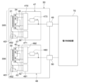
図8に示すように、基板30には、上記したコイル31、32、34~37、40~43のほかにも種々の電気部品が実装されている。具体的に、基板30には、複数のコンデンサ451、452、461、462、第1信号処理部47を構成するIC、第2信号処理部48を構成するIC、第1ターミナル49、および第2ターミナル50なども実装されている。
As shown in FIG. 8, in addition to the
そして、第1送信コイル31、2つの第1受信コイル34、36、2つの第2受信コイル35、37、2つのコンデンサ451、452、第1信号処理部47、および第1ターミナル49は、第1系統305を構成している。一方、第2送信コイル32、2つの第3受信コイル40、42、2つの第4受信コイル41、43、2つのコンデンサ461、462、第2信号処理部48、および第2ターミナル50は、第2系統306を構成している。これら第1系統305と第2系統306は電気回路として独立した構成となっているので、位置検出装置1は、第1系統305と第2系統306との一方が故障しても他方によって、回転部材20の回転位置を検出することができる。
The
第1、第2信号処理部47、48はそれぞれ、図示しないCPU、RAM、ROM、不揮発性リライタブルメモリ等を備えた車載マイクロコンピュータとしての構成を有している。すなわち、第1、第2信号処理部47、48はそれぞれ、非遷移的実体的記録媒体であるROMまたは不揮発性リライタブルメモリに格納されたコンピュータプログラムを読み出して実行する。このコンピュータプログラムが実行されることで、コンピュータプログラムに対応する方法が実行される。このような構成は、後述する電子制御装置72についても同様である。CPUは、Central Processing Unitの略であり、ROMは、Read Only Memoryの略であり、RAMは、Random Access Memoryの略である。
The first and second
第1信号処理部47には、第1送信コイル31、2つの第1受信コイル34、36、および2つの第2受信コイル35、37がそれぞれ接続されている。また、第1送信コイル31の両端と第1信号処理部47との間には、例えば、2つのコンデンサ451、452が直列に接続されていると共に、各コンデンサ451、452同士を接続する部分がグランドに接続されている。そして、第1信号処理部47は、基板30に固定された第1ターミナル49を介して、位置検出装置1の外部に設けられた電子制御装置72へ接続される。
The first
第2信号処理部48まわりの接続関係についてもこれと同様である。すなわち、第2信号処理部48には、第2送信コイル32、2つの第3受信コイル40、42、および2つの第4受信コイル41、43がそれぞれ接続されている。また、第2送信コイル32の両端と第2信号処理部48との間には、例えば、2つのコンデンサ461、462が直列に接続されていると共に、各コンデンサ461、462同士を接続する部分がグランドに接続されている。そして、第2信号処理部48は、基板30に固定された第2ターミナル50を介して外部の電子制御装置72へ接続される。このように、第1信号処理部47と第2信号処理部48は、回転部材20の回転位置(言い換えれば、回転角度)を電子制御装置72へ別々に出力する。
The same applies to the connection relationship around the second
次に、上記の第1信号処理部47の作動について説明する。
Next, the operation of the first
図8に示すように、第1信号処理部47は発振部471と受信部472とを備えている。発振部471は、第1送信コイル31の両端と接続されており、所定の周波数の交流電流を第1送信コイル31に対して印加する。これにより、第1送信コイル31は、受信コイル34~37、40~43を通過する部材軸方向Daの磁界を発生させる。この磁界によって、受信コイル34~37、40~43にそれぞれ誘導電流が流れる。
As shown in FIG. 8, the first
受信部472には、直列接続された2つの第1受信コイル34、36と、直列接続された2つの第2受信コイル35、37とがそれぞれ接続されている。受信部472は、その2つの第1受信コイル34、36からの出力に対し復調やAD変換を行って得られる変換信号(すなわち、図9の第1電圧値V1)を取得する。その2つの第1受信コイル34、36からの出力は、2つの第1受信コイル34、36の一方からの出力と他方からの出力とを合算したものになる。また、受信部472は、2つの第2受信コイル35、37からの出力に対し復調やAD変換を行って得られる変換信号(すなわち、図9の第2電圧値V2)も取得する。その2つの第2受信コイル35、37からの出力は、2つの第2受信コイル35、37の一方からの出力と他方からの出力とを合算したものになる。
The
そして、受信部472は、その取得した各変換信号に基づき、例えばそれらの変換信号を用いた逆正接関数を演算して回転部材20の回転角度(言い換えると、回転位置)を算出する。なお、第1、第2受信コイル34、36、35、37の電気信号における電気角θと回転部材20の回転角度(すなわち、機械角)との関係については、例えば第1ターゲット22、23および受信コイル34、36、35、37の大きさ等に応じて予め決定されている。そのため、電気角θに基づいて回転部材20を算出することができる。例えば本実施形態では、上記電気角θと機械角と関係は、何れの受信コイル群301a、302a、303a、304aでも同じになっている。
Then, the
受信部472は、このように第1、第2受信コイル34、36、35、37からの検出信号に基づき回転部材20の回転位置を算出または決定すると、その回転部材20の回転位置を示す信号を、第1ターミナル49を介して外部の電子制御装置72へ出力する。
When the
以上が、第1信号処理部47の基本的な作動である。なお、第2信号処理部48も第1信号処理部47と同様に発振部481と受信部482とを有している。その第2信号処理部48の発振部481は第1信号処理部47の発振部471と同様であり、第2信号処理部48の受信部482は第1信号処理部47の受信部472と同様である。第2信号処理部48の作動は、第1信号処理部47の作動と同様であるので、第2信号処理部48の作動の説明は省略する。
The above is the basic operation of the first
次に、回転部材20が回転した際の第1受信コイル34、36の第1電圧値V1および第2受信コイル35、37の第2電圧値V2について説明する。
Next, we will explain the first voltage value V1 of the first receiving coils 34 and 36 and the second voltage value V2 of the second receiving coils 35 and 37 when the rotating
例えば、第1送信コイル31に所定の周波数の交流電流が印加されると、それにより、第1一方側受信コイル群301aの第1一方側受信コイル34と第2一方側受信コイル35とを通過する部材軸方向Daの磁界が発生する。また、交流電流によって磁界が変化するため、電磁誘導により、第1一方側受信コイル34と第2一方側受信コイル35とのそれぞれに対し誘導起電力が発生する。
For example, when an alternating current of a predetermined frequency is applied to the first transmitting
そして、第1一方側ターゲット22が第1送信コイル31、第1一方側受信コイル34、第2一方側受信コイル35と対向すると、第1一方側ターゲット22に渦電流が発生すると共に渦電流に起因する磁界が発生する。このため、第1一方側受信コイル34と第2一方側受信コイル35とを通過する部材軸方向Daの磁界のうちの第1一方側ターゲット22と対向する部分を通過する磁界は、渦電流を起因とする磁界によって相殺される。
When the first one-
そして、回転部材20の回転に伴って、第1一方側受信コイル34と第2一方側受信コイル35とのそれぞれで第1一方側ターゲット22に対向する部位の位置および大きさが変化する。以上のことは、第1一方側受信コイル群301aを例にした説明であるが、このことは、第1他方側受信コイル群302aでも同様である。
As the rotating
このため、回転部材20の回転に伴い、第1受信コイル34、36に発生する第1電圧値V1および第2受信コイル35、37に発生する第2電圧値V2は、周期的に変化する。本実施形態では例えば、図9に示すように、第1受信コイル34、36に発生する第1電圧値V1は正弦波状となり、第2受信コイル35、37に発生する第2電圧値V2は、第1電圧値V1と同じ波長の余弦波状となる。
As a result, as the rotating
なお、第3受信コイル40、42に発生する電圧値、および第4受信コイル41、43に発生する電圧値も上記と同様であるので、その説明を省略する。 The voltage values generated in the third receiving coils 40 and 42 and the fourth receiving coils 41 and 43 are the same as those described above, so their explanation is omitted.
上述したように、本実施形態によれば、第1一方側ターゲット22は部材周方向Dcに往復移動する。そして、第1一方側ターゲット22は、第2一方側受信領域303および第2他方側受信領域304に対し第1一方側ターゲット22が部材軸方向Daの他方側に重ならない動作範囲W1a内で往復移動する。
As described above, according to this embodiment, the first one-
そのため、第2ターゲット24、25の位置を検出するための第3、第4受信コイル40、42、41、43を通る磁束に対し第1一方側ターゲット22が干渉することを避けることができる。従って、第3、第4受信コイル40、42、41、43の各出力値(すなわち、各検出信号)に第1一方側ターゲット22が及ぼす影響を低減することが可能である。
This makes it possible to prevent the first one-
また、第1一方側ターゲット22と第1他方側ターゲット23は、第2系統306の信号処理に影響を与えずに動作し、第2一方側ターゲット24と第2他方側ターゲット25は第1系統305の信号処理に影響を与えずに動作する。そのため、第1系統305と第2系統306との互いの独立性を保証することができる。
In addition, the first one-
(1)また、本実施形態によれば、第1一方側ターゲット22の動作範囲W1aは、部材周方向Dcでの第1一方側受信領域301の中心位置301bを中心として部材周方向Dcに振り分けられた範囲となっている。従って、第1一方側受信領域301が部材周方向Dcに有する長さを最大限活用して、第1一方側ターゲット22の動作範囲W1aを広くすることが可能である。
(1) In addition, according to this embodiment, the operating range W1a of the first one-
(2)また、本実施形態によれば、第1一方側ターゲット22は、部材周方向Dcにおいて第1一方側受信領域301の周方向一方端位置P1に対する他方側かつ第1一方側受信領域301の周方向他方端位置P2に対する一方側の範囲から食み出ることなく往復移動する。これにより、第3、第4受信コイル40、42、41、43の各出力値に第1一方側ターゲット22が及ぼす影響を更に低減することが可能である。
(2) Furthermore, according to this embodiment, the first one-
(3)また、本実施形態によれば、部材軸方向Daに沿う方向視において、基板30が有する全ての受信コイル34~37、40~43は、第1送信コイル31の内側に配置され且つ第2送信コイル32の内側に配置されている。
(3) Furthermore, according to this embodiment, when viewed in the direction along the member axis direction Da, all of the receiving coils 34 to 37, 40 to 43 of the
従って、例えば第1送信コイル31と第2送信コイル32との一方が断線などに起因して通電不能になったとしても、他方の送信コイルによって全ての受信コイル34~37、40~43に誘導電流を流すことが可能である。また、第1系統305に属する受信コイル34、36、35、37と第2系統306に属する受信コイル40、42、41、43とを第1送信コイル31と第2送信コイル32とで別々に囲む構成と比較して、第1、第2送信コイル31、32が必要とする領域を小さくできる。
Therefore, even if one of the first transmitting
(4)また、本実施形態によれば、受信コイル34~37、40~43が有するそれぞれの渦巻状部34a~43bは何れも、部材軸方向Daに沿う方向視で渦巻状のパターン形状を成している。従って、例えば各受信コイル34~37、40~43が正弦波もしくは余弦波を描くパターン形状によって形成される場合に比べて、基板30に形成される配線層数が少なくなり、より簡便に製造することが可能となる。
(4) In addition, according to this embodiment, each of the spiral portions 34a to 43b of the receiving coils 34 to 37 and 40 to 43 has a spiral pattern shape when viewed in the direction along the member axis direction Da. Therefore, the number of wiring layers formed on the
(5)また、本実施形態によれば、図1、図5に示すように、第1一方側ターゲット22は、第1他方側ターゲット23に対し回転軸心CLを挟んだ反対側に配置されている。そして、第1一方側受信コイル群301aは第1他方側受信コイル群302aに対し回転軸心CLを挟んだ反対側に配置されている。
(5) In addition, according to this embodiment, as shown in Figs. 1 and 5, the first one-
これにより、回転部材20の回転位置を表す位置検出装置1の出力に対し回転部材20の芯ズレが与える影響を低減できる構成、要するに回転部材20の芯ズレに強い構成を容易に得ることができる。
This makes it possible to easily obtain a configuration that can reduce the effect of misalignment of the rotating
例えば、図1において回転部材20が紙面上側へ芯ズレした場合を想定する。その場合、第1系統305について見ると、第1一方側受信領域301では、第1、第2一方側受信コイル34、35上に重なる第1一方側ターゲット22の投影面積が回転部材20の芯ズレに起因して減ることになる。これに対し、第1他方側受信領域302では、第1、第2他方側受信コイル36、37上に重なる第1他方側ターゲット23の投影面積が回転部材20の芯ズレに起因して増えることになる。そして、そのターゲットの投影面積が変化すれば、それに応じて受信コイルの出力も変化する。
For example, consider the case in FIG. 1 where the rotating
更に、部材周方向Dcの一方側から他方側への向きを正方向と仮定して、第2系統306について見ると、第2一方側ターゲット24は回転部材20の芯ズレに起因して進角し、これとは逆に、第2他方側ターゲット25は回転部材20の芯ズレに起因して遅角する。
Furthermore, assuming that the direction from one side to the other side of the member circumferential direction Dc is the positive direction, looking at the
このように、回転軸心CLを中心として互いに点対称に配置され第1系統305に属する第1一方側受信コイル群301aと第1他方側受信コイル群302aとの間では、回転部材20の芯ズレに起因して互いに逆の現象が生じる。これと同様に、回転軸心CLを中心として互いに点対称に配置され第2系統306に属する第2一方側受信コイル群303aと第2他方側受信コイル群304aとの間でも、回転部材20の芯ズレに起因して互いに逆の現象が生じる。
In this way, opposite phenomena occur between the first one-side receiver coil group 301a and the first other-side
従って、上記した逆の現象が第1系統305で生じることを利用して、第1系統305では、回転部材20の芯ズレに強い構成を容易に得ることができる。そして、上記した逆の現象が第2系統306で生じることを利用して、第2系統306でも、回転部材20の芯ズレに強い構成を容易に得ることができる。
Therefore, by utilizing the fact that the reverse phenomenon described above occurs in the
例えば本実施形態では、第1系統305において2つの第1受信コイル34、36は上記したように直列接続されているので、その2つの第1受信コイル34、36の間で、コイル出力に対する回転部材20の芯ズレの影響が相殺される。これと同様に、直列接続された2つの第2受信コイル35、37の間でも、コイル出力に対する回転部材20の芯ズレの影響が相殺される。このことは、第2系統306でも同様である。従って、上記のとおり、第1系統305において、回転部材20の芯ズレに強い構成を容易に得ることができると共に、第2系統306においても、回転部材20の芯ズレに強い構成を容易に得ることができる。
For example, in this embodiment, the two first receiving coils 34, 36 in the
なお、上記した特許文献1に示された角度位置センサーは、本実施形態の位置検出装置1と比較して、回転部材の芯ズレに対して弱いと考えられる。なぜなら、特許文献1の角度位置センサーでは、回転軸心を挟んで配置された2つの受信コイルの間で、コイル出力に対する回転部材の芯ズレの影響が相殺されるような構造が採用されていないからである。
The angular position sensor shown in the above-mentioned
また、本実施形態によれば、図2、図5に示すように、全ての送信および受信コイル31、32、34~37、40~43は1つの基板30に形成され、全てのターゲット22~25が基板30に対し部材軸方向Daで片側に配置されている。従って、例えば第1ターゲット22、23が基板30に対し部材軸方向Daの一方側に配置され第2ターゲット24、25が基板30に対し部材軸方向Daの他方側に配置される構成に比して、位置検出装置1の体格を小さくすることができる。
Furthermore, according to this embodiment, as shown in Figures 2 and 5, all the transmitting and receiving
(第2実施形態)
次に、第2実施形態について説明する。本実施形態では、前述の第1実施形態と異なる点を主として説明する。また、前述の実施形態と同一または均等な部分については省略または簡略化して説明する。このことは後述の実施形態の説明においても同様である。
Second Embodiment
Next, a second embodiment will be described. In this embodiment, differences from the first embodiment will be mainly described. Also, parts that are the same as or equivalent to the above-mentioned embodiment will be omitted or simplified. This also applies to the following embodiments.
図10に示すように、本実施形態では、受信コイル34~37、40~43のパターン形状が第1実施形態と異なっている。従って、本実施形態では、第1実施形態の渦巻状部34a~43b(図5参照)は設けられていない。 As shown in FIG. 10, in this embodiment, the pattern shapes of the receiving coils 34-37 and 40-43 are different from those in the first embodiment. Therefore, in this embodiment, the spiral portions 34a-43b (see FIG. 5) of the first embodiment are not provided.
なお、本実施形態でも第1実施形態と同様に、部材軸方向Daに沿う方向視において、全ての受信コイル34~37、40~43は、第1送信コイル31の内側に配置され且つ第2送信コイル32の内側に配置されている。そして、各受信コイル34~37、40~43は、互いに干渉しない(すなわち、重ならない)ように、ビア30dを介して異なる配線層が適宜接続されることで構成されている。
In this embodiment, as in the first embodiment, when viewed in the direction along the member axis direction Da, all of the receiving coils 34-37, 40-43 are arranged inside the first transmitting
本実施形態では、各受信コイル34~37、40~43は、順に積層された配線層のうちの隣合う2つの配線層がビア30dで接続されて構成されている。例えば本実施形態では、各受信コイル34~37、40~43は、基板30の他面30b側に位置する最表層の配線層と、最表層の次層となる配線層とが接続されて形成されている。図10における各受信コイル34~37、40~43の表示に関しては、基板30における最表層に形成される配線層を実線で示し、最表層の次層に形成される配線層を破線で示している。また、送信コイル31、32は、全て実線で表示されている。
In this embodiment, each of the receiving coils 34-37, 40-43 is configured by connecting two adjacent wiring layers of the wiring layers stacked in order by a via 30d. For example, in this embodiment, each of the receiving coils 34-37, 40-43 is formed by connecting the topmost wiring layer located on the
具体的に、第1一方側受信コイル34は第1波状部34dと第2波状部34eとを有している。その第1、第2波状部34d、34eはそれぞれ、部材軸方向Daに沿う方向視で正弦波状の曲線を描くパターン形状を成している。そして、第1、第2波状部34d、34eは、例えば接続配線パターンを介して直列接続され、閉ループを形成している。
Specifically, the first one-
また、第2一方側受信コイル35は第1波状部35dと第2波状部35eとを有している。その第1、第2波状部35d、35eはそれぞれ、部材軸方向Daに沿う方向視で第1一方側受信コイル34の第1、第2波状部34d、34eに対して部材周方向Dcに位相をずらした正弦波状の曲線を描くパターン形状を成している。そして、第1、第2波状部35d、35eは、例えば接続配線パターンを介して直列接続され、閉ループを形成している。例えば、第1、第2一方側受信コイル34、35の波状部34d、34e、35d、35eは、第1一方側ターゲット22の動作範囲W1a内の何れの位置でも、第1一方側ターゲット22に対し部材軸方向Daの一方側に重なるように配置されている。
The second one-
上記した受信コイル34、35を含む第1一方側受信コイル群301a以外の他の受信コイル群302a、303a、304aについても、上記と同様である。すなわち、第1他方側受信コイル36は、部材軸方向Daに沿う方向視で正弦波状の曲線を描くパターン形状を成し互いに直列接続された第1波状部36dと第2波状部36eとを有している。また、第2他方側受信コイル37は、部材軸方向Daに沿う方向視で上記第1、第2波状部36d、36eに対して部材周方向Dcに位相をずらした正弦波状の曲線を描くパターン形状を成し互いに直列接続された第1波状部37dと第2波状部37eとを有している。例えば、第1、第2他方側受信コイル36、37の波状部36d、36e、37d、37eは、第1他方側ターゲット23の動作範囲W1b内の何れの位置でも、第1他方側ターゲット23に対し部材軸方向Daの一方側に重なるように配置されている。
The above is also true for the other receiving
また、第3一方側受信コイル40は、部材軸方向Daに沿う方向視で正弦波状の曲線を描くパターン形状を成し互いに直列接続された第1波状部40dと第2波状部40eとを有している。また、第4一方側受信コイル41は、部材軸方向Daに沿う方向視で上記第1、第2波状部40d、40eに対して部材周方向Dcに位相をずらした正弦波状の曲線を描くパターン形状を成し互いに直列接続された第1波状部41dと第2波状部41eとを有している。例えば、第3、第4一方側受信コイル40、41の波状部40d、40e、41d、41eは、第2一方側ターゲット24の動作範囲W2a内の何れの位置でも、第2一方側ターゲット24に対し部材軸方向Daの一方側に重なるように配置されている。
The third one-
また、第3他方側受信コイル42は、部材軸方向Daに沿う方向視で正弦波状の曲線を描くパターン形状を成し互いに直列接続された第1波状部42dと第2波状部42eとを有している。また、第4他方側受信コイル43は、部材軸方向Daに沿う方向視で上記第1、第2波状部42d、42eに対して部材周方向Dcに位相をずらした正弦波状の曲線を描くパターン形状を成し互いに直列接続された第1波状部43dと第2波状部43eとを有している。例えば、第3、第4他方側受信コイル42、43の波状部42d、42e、43d、43eは、第2他方側ターゲット25の動作範囲W2b内の何れの位置でも、第2他方側ターゲット25に対し部材軸方向Daの一方側に重なるように配置されている。
The third other-
なお、本実施形態では、第1一方側受信領域301の周方向一方端位置P1は、部材周方向Dcにおける第2一方側受信コイル35の一方側の端位置に一致する。そして、第1一方側受信領域301の周方向他方端位置P2は、部材周方向Dcにおける第2一方側受信コイル35の他方側の端位置に一致する。この関係は、第1他方側受信領域302、第2一方側受信領域303、および第2他方側受信領域304に関しても同様である。
In this embodiment, the circumferential one end position P1 of the first one-
(1)上述したように、本実施形態によれば、受信コイル34~37、40~43が有するそれぞれの波状部34d~43eは何れも、部材軸方向Daに沿う方向視で正弦波状の曲線を描くパターン形状を成している。従って、位相差を有する正弦波もしくは余弦波の電気信号を受信コイル34~37、40~43から出力させることが可能である。なお、上記の波状部34d~43eは、波状部34d、34e、35d、35e、36d、36e、37d、37e、40d、40e、41d、41e、42d、42e、43d、43eを意味する。 (1) As described above, according to this embodiment, each of the wavy portions 34d to 43e of the receiving coils 34 to 37 and 40 to 43 has a pattern shape that draws a sine-wave curve when viewed in the direction along the member axis direction Da. Therefore, it is possible to output sine wave or cosine wave electrical signals with a phase difference from the receiving coils 34 to 37 and 40 to 43. Note that the above wavy portions 34d to 43e refer to wavy portions 34d, 34e, 35d, 35e, 36d, 36e, 37d, 37e, 40d, 40e, 41d, 41e, 42d, 42e, 43d, and 43e.
以上説明したことを除き、本実施形態は第1実施形態と同様である。そして、本実施形態では、前述の第1実施形態と共通の構成から奏される効果を第1実施形態と同様に得ることができる。 Except for what has been described above, this embodiment is similar to the first embodiment. Furthermore, in this embodiment, the same effects as those of the first embodiment can be obtained from the configuration common to the first embodiment described above.
(第3実施形態)
次に、第3実施形態について説明する。本実施形態では、前述の第1実施形態と異なる点を主として説明する。
Third Embodiment
Next, a third embodiment will be described. In this embodiment, differences from the first embodiment will be mainly described.
図11に示すように、本実施形態の基板30は、第1実施形態の第1送信コイル31(図5参照)に替えて2つの第1送信コイル311、312を有し、第1実施形態の第2送信コイル32(図5参照)に替えて2つの第2送信コイル321、322を有している。
As shown in FIG. 11, the
その2つの第1送信コイル311、312とは、第1一方側送信コイル311と第1他方側送信コイル312とのことである。また、2つの第2送信コイル321、322とは、第2一方側送信コイル321と第2他方側送信コイル322とのことである。
The two first transmitting coils 311, 312 are the first one-
第1一方側送信コイル311と第1他方側送信コイル312は直列接続されている。そのため、例えば第1一方側送信コイル311に電流が流れると、それと同時に第1他方側送信コイル312にも電流が流れる。このとき、第1一方側受信コイル群301aまわりで第1一方側送信コイル311に流れる電流の向きと、第1他方側受信コイル群302aまわりで第1他方側送信コイル312に流れる電流の向きは同じになる。要するに、第1一方側送信コイル311で時計回りに電流が流れれば第1他方側送信コイル312でも時計回りに電流が流れ、第1一方側送信コイル311で反時計回りに電流が流れれば第1他方側送信コイル312でも反時計回りに電流が流れる。
The first one-
そして、第2一方側送信コイル321と第2他方側送信コイル322も直列接続されている。そのため、例えば第2一方側送信コイル321に電流が流れると、それと同時に第2他方側送信コイル322にも電流が流れる。このとき、第2一方側受信コイル群303aまわりで第2一方側送信コイル321に流れる電流の向きと、第2他方側受信コイル群304aまわりで第2他方側送信コイル322に流れる電流の向きは同じになる。要するに、第2一方側送信コイル321で時計回りに電流が流れれば第2他方側送信コイル322でも時計回りに電流が流れ、第2一方側送信コイル321で反時計回りに電流が流れれば第2他方側送信コイル322でも反時計回りに電流が流れる。
The second one-
また、部材軸方向Daに沿う方向視において、第1、第2一方側受信コイル34、35は第1一方側送信コイル311の内側に配置される一方で、他の受信コイル36、37、40~43は第1一方側送信コイル311の外側に配置されている。従って、第1一方側送信コイル311に交流電流が流れると、その第1一方側送信コイル311への通電による電磁誘導によって、誘導電流が第1、第2一方側受信コイル34、35に流れる。
When viewed in the direction along the member axis Da, the first and second one-side receiving coils 34, 35 are arranged inside the first one-
また、部材軸方向Daに沿う方向視において、第1、第2他方側受信コイル36、37は第1他方側送信コイル312の内側に配置される一方で、他の受信コイル34、35、40~43は第1他方側送信コイル312の外側に配置されている。従って、第1他方側送信コイル312に交流電流が流れると、その第1他方側送信コイル312への通電による電磁誘導によって、誘導電流が第1、第2他方側受信コイル36、37に流れる。
When viewed in the direction along the member axis Da, the first and second other-side receiving coils 36, 37 are arranged inside the first other-
また、部材軸方向Daに沿う方向視において、第3、第4一方側受信コイル40、41は第2一方側送信コイル321の内側に配置される一方で、他の受信コイル34~37、42、43は第2一方側送信コイル321の外側に配置されている。従って、第2一方側送信コイル321に交流電流が流れると、その第2一方側送信コイル321への通電による電磁誘導によって、誘導電流が第3、第4一方側受信コイル40、41に流れる。
When viewed in the direction along the member axis Da, the third and fourth one-side receiving coils 40 and 41 are arranged inside the second one-
また、部材軸方向Daに沿う方向視において、第3、第4他方側受信コイル42、43は第2他方側送信コイル322の内側に配置される一方で、他の受信コイル34~37、40、41は第2他方側送信コイル322の外側に配置されている。従って、第2他方側送信コイル322に交流電流が流れると、その第2他方側送信コイル322への通電による電磁誘導によって、誘導電流が第3、第4他方側受信コイル42、43に流れる。
When viewed in the direction along the member axis Da, the third and fourth other-side receiving coils 42 and 43 are arranged inside the second other-
そして、複数の送信コイル311、312、321、322は、第1一方側送信コイル311、第2他方側送信コイル322、第1他方側送信コイル312、第2一方側送信コイル321の順に部材周方向Dcの一方側から他方側へ相互間隔をあけて並んで配置されている。それらの送信コイル311、312、321、322の個々の形状は扇形状を成し、送信コイル311、312、321、322は全体として、回転軸心CLを中心とした円環形状を成すように並んでいる。
The multiple transmitting coils 311, 312, 321, 322 are arranged in the order of the first one-
以上説明したことを除き、第1一方側送信コイル311と第1他方側送信コイル312は第1実施形態の第1送信コイル31と同様であり、第2一方側送信コイル321と第2他方側送信コイル322は第1実施形態の第2送信コイル32と同様である。
Except as described above, the first one-
(1)上述した送信コイル311、312、321、322の構成により、受信コイル群301a、302a、303a、304a毎に別々に、受信コイルに対する電磁誘導を生じさせることが可能である。
(1) The configuration of the transmitting coils 311, 312, 321, and 322 described above makes it possible to generate electromagnetic induction in the receiving coils separately for each of the receiving
なお、本実施形態では、各送信コイル311、312、321、322は、基板30において同じ配線層に形成されていても差し支えない。
In this embodiment, the transmission coils 311, 312, 321, and 322 may be formed in the same wiring layer on the
以上説明したことを除き、本実施形態は第1実施形態と同様である。そして、本実施形態では、前述の第1実施形態と共通の構成から奏される効果を第1実施形態と同様に得ることができる。 Except for what has been described above, this embodiment is similar to the first embodiment. Furthermore, in this embodiment, the same effects as those of the first embodiment can be obtained from the configuration common to the first embodiment described above.
(第4実施形態)
次に、第4実施形態について説明する。本実施形態では、前述の第3実施形態と異なる点を主として説明する。
Fourth Embodiment
Next, a fourth embodiment will be described. In this embodiment, differences from the third embodiment will be mainly described.
図12に示すように、本実施形態の各受信コイル34~37、40~43は、第3実施形態のパターン形状に替えて、第2実施形態のパターン形状を有している。 As shown in FIG. 12, each of the receiving coils 34-37 and 40-43 in this embodiment has the pattern shape of the second embodiment instead of the pattern shape of the third embodiment.
すなわち、本実施形態では、渦巻状部34a~43b(図11参照)は設けられていない。その替わりに、第1一方側受信コイル34は、第2実施形態と同様の第1波状部34dと第2波状部34eとを有し、第2一方側受信コイル35は、第2実施形態と同様の第1波状部35dと第2波状部35eとを有している。また、第1他方側受信コイル36は、第2実施形態と同様の第1波状部36dと第2波状部36eとを有し、第2他方側受信コイル37は、第2実施形態と同様の第1波状部37dと第2波状部37eとを有している。
That is, in this embodiment, the spiral portions 34a to 43b (see FIG. 11) are not provided. Instead, the first one-
また、第3一方側受信コイル40は、第2実施形態と同様の第1波状部40dと第2波状部40eとを有し、第4一方側受信コイル41は、第2実施形態と同様の第1波状部41dと第2波状部41eとを有している。また、第3他方側受信コイル42は、第2実施形態と同様の第1波状部42dと第2波状部42eとを有し、第4他方側受信コイル43は、第2実施形態と同様の第1波状部43dと第2波状部43eとを有している。
The third one-
以上説明したことを除き、本実施形態は第3実施形態と同様である。そして、本実施形態では、前述の第3実施形態と共通の構成から奏される効果を第3実施形態と同様に得ることができる。 Except for what has been described above, this embodiment is similar to the third embodiment. Furthermore, in this embodiment, the same effects as those of the third embodiment can be obtained from the configuration common to the third embodiment.
(第5実施形態)
次に、第5実施形態について説明する。本実施形態では、前述の第1実施形態と異なる点を主として説明する。
Fifth Embodiment
Next, a fifth embodiment will be described. In this embodiment, differences from the first embodiment will be mainly described.
図13に示すように、第1信号処理部47は第1故障検知部473を含み、第2信号処理部48は第2故障検知部483を含んでいる。本実施形態では、この点が第1実施形態と異なっている。
As shown in FIG. 13, the first
具体的に、第1故障検知部473は、図14に示された制御処理を実行する。図14のフローチャートは、周期的に繰り返し実行される。
Specifically, the first
図14に示すように、第1故障検知部473は、まず、ステップS01にて、直列接続された2つの第1受信コイル34、36から出力された検出信号を受信部472から取得する。それと共に、第1故障検知部473は、直列接続された2つの第2受信コイル35、37から出力された検出信号も受信部472から取得する。図9に示すように、その第1受信コイル34、36から出力された検出信号の大きさは、具体的には第1電圧値V1であり、第2受信コイル35、37から出力された検出信号の大きさは、具体的には第2電圧値V2である。
As shown in FIG. 14, the first
ここで、上記したように、第1電圧値V1は、回転部材20の回転位置に対応した電気角θに対し正弦波状に変化し、第2電圧値V2は第1電圧値V1に対し同期して、その電気角θに対し余弦波状に変化する。要するに、第1電圧値V1と第2電圧値V2は、電気角θに対し、図9に示すように変化する。このことと、三角関数の公式である下記式F1とから、下記式F2から算出される判定値Vxは、各検出信号に誤差が無ければ、電気角θが変化しても一定の値になると考えられる。
sin2θ+cos2θ=1 ・・・(F1)
Vx=V12+V22 ・・・(F2)
As described above, the first voltage value V1 varies in a sine wave manner with respect to the electrical angle θ corresponding to the rotational position of the rotating
sin2θ + cos2θ =1 (F1)
Vx=V1 2 +V2 2 ... (F2)
そこで、図14のステップS01では、第1電圧値V1と第2電圧値V2とに基づき、判定値Vxが上記式F2から算出される。ステップS01の次はステップS02へ進む。 Therefore, in step S01 of FIG. 14, the judgment value Vx is calculated from the above formula F2 based on the first voltage value V1 and the second voltage value V2. After step S01, the process proceeds to step S02.
ステップS02では、第1故障検知部473は、判定値Vxに基づいて故障を検知する。このステップS02で検知される故障とは、具体的に言えば、位置検出装置1のうち、第1受信コイル34、36から出力された検出信号または第2受信コイル35、37から出力された検出信号に関係する構成部分の故障である。
In step S02, the first
詳細には、上記したように電気角θに対し判定値Vxは変動しないのが理想であるので、電気角θに対する判定値Vxの変動が所定の限度を超えた場合に、第1故障検知部473は、故障が発生したと判断する。別言すると、第1故障検知部473は、故障が検知されたと判定する。
In detail, as described above, it is ideal for the determination value Vx not to vary with respect to the electrical angle θ, so when the variation of the determination value Vx with respect to the electrical angle θ exceeds a predetermined limit, the first
例えば、上記式F2から算出された判定値Vxが、その判定値Vxの理想値を含む所定の許容範囲から外れた場合に、故障が検知されたと判定されてもよい。その判定値Vxの理想値とは、第1電圧値V1と第2電圧値V2とに誤差が無いとした場合の判定値Vxである。或いは、上記式F2から算出された判定値Vxが電気角θに対し変動する割合(すなわち、変動率)が所定の限度値を超えた場合に、故障が検知されたと判定されてもよい。 For example, it may be determined that a fault has been detected when the determination value Vx calculated from the above formula F2 falls outside a predetermined tolerance range including the ideal value of the determination value Vx. The ideal value of the determination value Vx is the determination value Vx when there is no error between the first voltage value V1 and the second voltage value V2. Alternatively, it may be determined that a fault has been detected when the rate at which the determination value Vx calculated from the above formula F2 fluctuates with respect to the electrical angle θ (i.e., the rate of fluctuation) exceeds a predetermined limit value.
ステップS02において、故障が検知されたと判定された場合には、ステップS03へ進む。その一方で、故障が検知されたと判定されなかった場合には、本フローチャートは終了し再びステップS01から開始する。 If it is determined in step S02 that a malfunction has been detected, the process proceeds to step S03. On the other hand, if it is determined that a malfunction has not been detected, the process ends and starts again from step S01.
ステップS03では、第1故障検知部473は、故障が検知された旨を出力する。この故障が検知された旨の出力は、第1ターミナル49を介して外部の電子制御装置72へ入力される。
In step S03, the first
第1電圧値V1と第2電圧値V2とに基づく故障の検知は、上記のとおりである。なお、図13に示す第2故障検知部483の作動は、上記した第1故障検知部473の作動と同様であるので、第2故障検知部483の作動の説明は省略する。
The detection of a fault based on the first voltage value V1 and the second voltage value V2 is as described above. Note that the operation of the second
(1)上述したように、本実施形態によれば、図13の第1故障検知部473は、上記式F2から得られる判定値Vxに基づいて故障を検知する。従って、構造上の付加を必要とせずに、故障を検知することができる。例えば基板30のサイズ拡大を必要とせずに、高い機能安全を設けることができる。そして、故障検知のために必要なパターン数が増えるわけでもないので、受信コイル一つ当たりのパターン面積を大きくしやすく、検出信号の振幅確保や回転部材20の芯ズレに対するロバスト性向上を図ることができる。
(1) As described above, according to this embodiment, the first
ここで、本実施形態における作用効果を説明するために、次のような第1比較例を想定する。例えば、その第1比較例では、第1系統305から出力される第1のセンサ出力が、図15の破線L1のように回転部材20の回転角度が大きくなるほど大きくなる。そして、第2系統306から出力される第2のセンサ出力が、図15の実線L2のように回転部材20の回転角度が大きくなるほど小さくなる。要するに、第1のセンサ出力と第2のセンサ出力とが、回転部材20の回転角度に対し互いに逆の相関になるように設定されている。
Here, in order to explain the action and effect of this embodiment, the following first comparative example is assumed. For example, in this first comparative example, the first sensor output output from the
このような第1比較例の場合、第1のセンサ出力と第2のセンサ出力との和は正常で誤差が無ければ一定値になるので、その第1、第2のセンサ出力の和を監視することで故障の検知(別言すれば、異常の判定)を行うことができる。しかしながら、第1比較例では、故障の検知はできるものの、故障が検知されたときに、第1、第2のセンサ出力の何れが正常値かを判断することはできない。 In the case of the first comparative example, the sum of the first sensor output and the second sensor output is a constant value if it is normal and there is no error, so by monitoring the sum of the first and second sensor outputs, it is possible to detect a fault (in other words, to determine an abnormality). However, in the first comparative example, although it is possible to detect a fault, it is not possible to determine which of the first and second sensor outputs is the normal value when a fault is detected.
これに対し、本実施形態では、第1系統305と第2系統306とのそれぞれで故障か否かを判定できる。そのため、第1系統305と第2系統306との一方で故障が検知されたときにも、正常な他方によって回転部材20の回転角度を検出することが可能である。
In contrast, in this embodiment, it is possible to determine whether or not there is a malfunction in each of the
以上説明したことを除き、本実施形態は第1実施形態と同様である。そして、本実施形態では、前述の第1実施形態と共通の構成から奏される効果を第1実施形態と同様に得ることができる。 Except for what has been described above, this embodiment is similar to the first embodiment. Furthermore, in this embodiment, the same effects as those of the first embodiment can be obtained from the configuration common to the first embodiment described above.
なお、本実施形態は第1実施形態に基づいた変形例であるが、本実施形態を前述の第2~第4実施形態の何れかと組み合わせることも可能である。 Note that this embodiment is a modification based on the first embodiment, but it is also possible to combine this embodiment with any of the second to fourth embodiments described above.
(第6実施形態)
次に、第6実施形態について説明する。本実施形態では、前述の第1実施形態と異なる点を主として説明する。
Sixth Embodiment
Next, a sixth embodiment will be described. In this embodiment, differences from the first embodiment will be mainly described.
図16~図18に示すように、本実施形態では、第1実施形態の回転部材20(図1参照)が二部品構成になっている。すなわち、本実施形態では、位置検出装置1は、その第1実施形態の回転部材20に替えて、互いに組み合わされた第1ターゲット部材16と第2ターゲット部材18とを備えている。本実施形態の第1ターゲット部材16と第2ターゲット部材18は全体で第1実施形態の回転部材20に相当するので、回転軸心CLは、第1ターゲット部材16および第2ターゲット部材18の回転中心である。また、第1ターゲット部材16と第2ターゲット部材18は、第1実施形態の回転部材20と同様に金属で構成されている。
As shown in Figures 16 to 18, in this embodiment, the rotating member 20 (see Figure 1) of the first embodiment is made up of two parts. That is, in this embodiment, the
なお、本実施形態の第1ターゲット部材16と第2ターゲット部材18とを組み合わせた全体の形状は、部材軸方向Daに沿う方向視で、第1実施形態の回転部材20と同じである。例えば、部材軸方向Daに沿う方向視で、各ターゲット22~25の形状および配置は第1実施形態と同じである。図16は、図17のXVI-XVI断面を示した断面図である。
The overall shape of the combination of the
第1ターゲット部材16は、第1連結部161と、2つの第1ターゲット22、23とを有している。また、第2ターゲット部材18は、第2連結部181と、2つの第2ターゲット24、25とを有している。例えば、第1ターゲット部材16は、第1連結部161と2つの第1ターゲット22、23とを含んだ単一の部品として構成され、第2ターゲット部材18は、第2連結部181と2つの第2ターゲット24、25とを含んだ単一の部品として構成されている。
The
第1連結部161と第2連結部181は全体で第1実施形態の連結部21に相当する。具体的に、第1連結部161は、第1ターゲット部材16の中で中央部分に配置され、回転軸心CLを中心とした円環形状を成している。そして、2つの第1ターゲット22、23はそれぞれ、第1連結部161から部材径方向Drの外側に突き出るように形成されると共に、第2連結部181に対し部材径方向Drの外側に配置されている。第1連結部161の内側には、第1連結部161を部材軸方向Daに貫通した第1嵌入孔161aが形成され、その第1嵌入孔161aには回転軸70が嵌入されている。これにより、第1連結部161は、回転軸70に対し相対回転不能となるように第2ターゲット部材18を介さずに連結されている。
The first connecting
また、第2連結部181は、第1連結部161に対し部材軸方向Daの一方側に積層配置されている。そして、第2連結部181は、部材軸方向Daに沿う方向視で第1連結部161と同様の形状を成している。
The second connecting
すなわち、第2連結部181は、第2ターゲット部材18の中で中央部分に配置され、回転軸心CLを中心とした円環形状を成している。そして、2つの第2ターゲット24、25はそれぞれ、第2連結部181から部材径方向Drの外側に突き出るように形成されると共に、第1連結部161に対し部材径方向Drの外側に配置されている。第2連結部181の内側には、第2連結部181を部材軸方向Daに貫通した第2嵌入孔181aが形成されている。
That is, the second connecting
その第2嵌入孔181aは第1嵌入孔161aと同心かつ同径であり、第1嵌入孔161aから連続して部材軸方向Daにつながるように配置されている。要するに、第1嵌入孔161aと第2嵌入孔181aは、直列に並ぶことで1つの貫通孔を形成している。そして、第2嵌入孔181aにも、第1嵌入孔161aと同様に回転軸70が嵌入されている。これにより、第2連結部181は、回転軸70に対し相対回転不能となるように第1ターゲット部材16を介さずに連結されている。
The
詳細には、回転軸70は、円柱状の軸本体701と、2つの突出部702b、702cとを有している。その軸本体701は、回転軸70のうち、第1嵌入孔161aおよび第2嵌入孔181aの内側に嵌入され収まる部分である。2つの突出部702b、702cのうちの一方である一方側突出部702bと、2つの突出部702b、702cのうちの他方である他方側突出部702cはそれぞれ、軸本体701から部材径方向Drの外側へ突き出ている。一方側突出部702bと他方側突出部702cはそれぞれ、矩形状の断面を有して部材軸方向Daへ延伸し、部材周方向Dcに相互間隔をあけて配置されている。例えば、この2つの突出部702b、702cは軸本体701と一体構成であってもよいし、軸本体701に設けられたキー溝に嵌め込まれたキー部材で構成されていてもよい。
In detail, the rotating
また、第1連結部161には、上記した第1嵌入孔161aのほかに、その第1嵌入孔161aに連結した2つの第1嵌入溝161b、161cが形成されている。その2つの第1嵌入溝161b、161cのうちの一方は第1一方嵌入溝161bと称され、2つの第1嵌入溝161b、161cのうちの他方は第1他方嵌入溝161cと称される。部材軸方向Daに沿う方向視で、この2つの第1嵌入溝161b、161cはそれぞれ、第1嵌入孔161aから部材径方向Drの外側へ窪んだ溝状に形成され、部材周方向Dcに相互間隔をあけて配置されている。
In addition to the
これと同様に、第2連結部181には、上記した第2嵌入孔181aのほかに、その第2嵌入孔181aに連結した2つの第2嵌入溝181b、181cが形成されている。その2つの第2嵌入溝181b、181cのうちの一方は第2一方嵌入溝181bと称され、2つの第2嵌入溝181b、181cのうちの他方は第2他方嵌入溝181cと称される。部材軸方向Daに沿う方向視で、この2つの第2嵌入溝181b、181cはそれぞれ、第2嵌入孔181aから部材径方向Drの外側へ窪んだ溝状に形成され、部材周方向Dcに相互間隔をあけて配置されている。
Similarly, in addition to the
更に言うと、部材軸方向Daに沿う方向視で、第2一方嵌入溝181bは第1一方嵌入溝161bに対し同形状で同じ配置とされ、第2他方嵌入溝181cは第1他方嵌入溝161cに対し同形状で同じ配置とされている。要するに、第1一方嵌入溝161bと第2一方嵌入溝181bは直列に並ぶことで、連続して部材軸方向Daにつながるように配置され、部材軸方向Daに延伸した1つの溝を形成している。また同様に、第1他方嵌入溝161cと第2他方嵌入溝181cも直列に並ぶことで、連続して部材軸方向Daにつながるように配置され、部材軸方向Daに延伸した1つの溝を形成している。
Moreover, when viewed in the direction along the component axis Da, the second one-side
そして、第1一方嵌入溝161bと第2一方嵌入溝181bには回転軸70の一方側突出部702bが嵌め入れられ、第1他方嵌入溝161cと第2他方嵌入溝181cには回転軸70の他方側突出部702cが嵌め入れられている。
The one-
第1ターゲット部材16において、第1一方側ターゲット22の対向面22aと第1他方側ターゲット23の対向面23aはそれぞれ、第1連結部161よりも部材軸方向Daの一方側に配置されている。そのため、第1一方側ターゲット22の対向面22aと第1連結部161との間には部材軸方向Daの段差が形成され、第1他方側ターゲット23の対向面23aと第1連結部161との間にも部材軸方向Daの段差が形成されている。
In the
これにより、本実施形態でも第1実施形態と同様に、基板30と4つのターゲット22~25の対向面22a、23a、24a、25aのそれぞれとの軸方向間隔AGが互いに揃えられている。別言すれば、その軸方向間隔AGは、基板30と4つのターゲット22~25の対向面22a、23a、24a、25aのそれぞれとの間の何れにおいても同じ大きさになっている。
As a result, in this embodiment, as in the first embodiment, the axial distances AG between the
また、本実施形態でも第1実施形態と同様に、4つのターゲット22~25の部材軸方向Daの厚みは互いに同じ大きさになっている。
In this embodiment, as in the first embodiment, the thicknesses of the four
(1)上述したように、本実施形態によれば、2つの第1ターゲット22、23を含む第1ターゲット部材16は、回転軸70に対し相対回転不能となるように第2ターゲット部材18を介さずに連結されている。そして、2つの第2ターゲット24、25を含む第2ターゲット部材18は、回転軸70に対し相対回転不能となるように第1ターゲット部材16を介さずに連結されている。
(1) As described above, according to this embodiment, the
従って、例えば4つのターゲット22~25が単一の部品に含まれている場合と比較して、第1ターゲット22、23と第2ターゲット24、25とのうちの一方の故障が他方に与える影響を低減し又は防止することができる。これにより、位置検出装置1の冗長性を高めることが可能である。
Therefore, compared to a case where, for example, the four
例えば、第1、第2ターゲット部材16、18の故障として、摩耗によりターゲットの位置が正常時に対し数度ずれたり、ターゲットと基板30との軸方向間隔AGが正常時に対し変わることが想定される。そのような故障が第1、第2ターゲット部材16、18の一方で生じても、その故障は他方のターゲット部材には影響しにくく、その他方のターゲット部材によって回転軸70の回転位置を検出することが可能である。
For example, a failure of the first and
また、第1、第2ターゲット部材16、18の一方の故障として、上記した摩耗以外に、その一方のターゲット部材の僅かな変形や部材周方向Dcへの僅かなズレなども想定される。そのような場合にも、その故障が他方のターゲット部材には影響しにくく、その他方のターゲット部材によって回転軸70の回転位置を検出することが可能である。
In addition to the wear described above, a failure of one of the first and
(2)また、本実施形態によれば、第1嵌入孔161aと第2嵌入孔181aは互いに部材軸方向Daにつながるように配置されている。第1一方嵌入溝161bと第2一方嵌入溝181bも互いに部材軸方向Daにつながるように配置され、第1他方嵌入溝161cと第2他方嵌入溝181cも互いに部材軸方向Daにつながるように配置されている。そして、第1一方嵌入溝161bと第2一方嵌入溝181bには回転軸70の一方側突出部702bが嵌め入れられ、第1他方嵌入溝161cと第2他方嵌入溝181cには回転軸70の他方側突出部702cが嵌め入れられている。
(2) In addition, according to this embodiment, the
従って、第1ターゲット部材16が回転軸70に対し相対回転不能となるように第2ターゲット部材18を介さずに連結され、且つ、第2ターゲット部材18が回転軸70に対し相対回転不能となるように第1ターゲット部材16を介さずに連結される。そして、この第1、第2ターゲット部材16、18が回転軸70に連結される構成を簡素な構造で実現することができる。
Therefore, the
(3)また、本実施形態によれば、2つの第1ターゲット22、23の対向面22a、23aはそれぞれ、第1連結部161よりも部材軸方向Daの一方側に配置されている。これにより、基板30と第1ターゲット22、23の対向面22a、23aとの間の軸方向間隔AGと、基板30と第2ターゲット24、25の対向面24a、25aとの間の軸方向間隔AGとが互いに揃えられている。そのため、第1ターゲット部材16と第2ターゲット部材18とを組み合わせて回転軸70へ取り付けやすくすると共に、各受信コイル34~37、40~43の出力を同程度の大きさにすることが可能である。
(3) In addition, according to this embodiment, the opposing
以上説明したことを除き、本実施形態は第1実施形態と同様である。そして、本実施形態では、前述の第1実施形態と共通の構成から奏される効果を第1実施形態と同様に得ることができる。 Except for what has been described above, this embodiment is similar to the first embodiment. Furthermore, in this embodiment, the same effects as those of the first embodiment can be obtained from the configuration common to the first embodiment described above.
なお、本実施形態は第1実施形態に基づいた変形例であるが、本実施形態を前述の第2~第5実施形態の何れかと組み合わせることも可能である。 Note that this embodiment is a modification based on the first embodiment, but it is also possible to combine this embodiment with any of the second to fifth embodiments described above.
(第7実施形態)
次に、第7実施形態について説明する。
Seventh Embodiment
Next, a seventh embodiment will be described.
特許文献1に記載された角度位置センサーは、電磁誘導を利用して、回転軸心まわりに回転する被検出体としての回転部材の回転位置を検出する。具体的に、特許文献1の角度位置センサーは、交流磁界を発生させる一対の送信コイルと、一対の受信コイル群とを備えている。
The angular position sensor described in
その一対の受信コイル群はそれぞれ複数の受信コイルを含み、一対のうちの一方の受信コイル群は他方の受信コイル群に対し回転軸心を挟んだ反対側に配置されている。そして、一対の送信コイルのうちの一方は上記一方の受信コイル群を囲み、一対の送信コイルのうちの他方は上記他方の受信コイル群を囲むように形成されている。 Each of the pair of receiving coil groups includes multiple receiving coils, and one of the pair of receiving coil groups is disposed on the opposite side of the rotation axis from the other receiving coil group. One of the pair of transmitting coils is formed to surround the one receiving coil group, and the other of the pair of transmitting coils is formed to surround the other receiving coil group.
ここで、特許文献1の角度位置センサーのような位置検出装置では、送信コイルと受信コイルとを有する基板に対し、回転部材が芯ズレすることが懸念される。
Here, in a position detection device such as the angular position sensor of
しかしながら、特許文献1の角度位置センサーでは、基板に対する回転部材の芯ズレに対し何ら対策が為されていない。そのため、回転部材の回転位置を表す角度位置センサーの出力に対し回転部材の芯ズレが与える影響が大きく、例えば、その回転部材の芯ズレが、回転部材の回転位置の検出精度を低下させることにつながる。
However, the angular position sensor in
これに対し、本実施形態では、回転部材の回転位置を表す位置検出装置の出力に対し回転部材の芯ズレが与える影響を低減できる構成、要するに回転部材の芯ズレに強い構成を容易に得ることができるようになっている。 In contrast, in this embodiment, it is possible to easily obtain a configuration that can reduce the effect of misalignment of the rotating member on the output of the position detection device that indicates the rotational position of the rotating member, in other words, a configuration that is resistant to misalignment of the rotating member.
具体的に、本実施形態は第1実施形態と同様である。従って、本実施形態では、前述の第1実施形態と共通の構成から奏される効果を第1実施形態と同様に得ることができる。 Specifically, this embodiment is similar to the first embodiment. Therefore, in this embodiment, the effects achieved by the configuration common to the first embodiment described above can be obtained in the same way as in the first embodiment.
(第7実施形態のまとめ)
第7実施形態は、上記のように構成されている。このため、まとめると、第7実施形態は、以下の観点を備えているといえる。
(Summary of the Seventh Embodiment)
The seventh embodiment is configured as described above. Therefore, in summary, it can be said that the seventh embodiment has the following advantages.
[観点1]
位置検出装置であって、
第1一方側ターゲット(22)と第1他方側ターゲット(23)と第2一方側ターゲット(24)と第2他方側ターゲット(25)とを有し、所定の回転軸心(CL)を中心に回転する回転部材(16、18、20)と、
第1送信コイル(31、311、312)、第2送信コイル(32、321、322)、前記第1送信コイルへの通電による電磁誘導によって前記第1一方側ターゲットの位置に応じた誘導起電力が生じ第1一方側受信コイル群(301a)を構成する第1一方側受信コイル(34)と第2一方側受信コイル(35)、前記第1送信コイルへの通電による電磁誘導によって前記第1他方側ターゲットの位置に応じた誘導起電力が生じ第1他方側受信コイル群(302a)を構成する第1他方側受信コイル(36)と第2他方側受信コイル(37)、前記第2送信コイルへの通電による電磁誘導によって前記第2一方側ターゲットの位置に応じた誘導起電力が生じ第2一方側受信コイル群(303a)を構成する第3一方側受信コイル(40)と第4一方側受信コイル(41)、および前記第2送信コイルへの通電による電磁誘導によって前記第2他方側ターゲットの位置に応じた誘導起電力が生じ第2他方側受信コイル群(304a)を構成する第3他方側受信コイル(42)と第4他方側受信コイル(43)を有し、前記第1一方側ターゲットと前記第1他方側ターゲットと前記第2一方側ターゲットと前記第2他方側ターゲットとに対向し、前記回転軸心の軸方向(Da)を法線方向とし、且つ前記第1一方側ターゲットと前記第1他方側ターゲットと前記第2一方側ターゲットと前記第2他方側ターゲットとに対し前記軸方向の一方側に配置された基板(30)とを備え、
前記第1一方側受信コイルと前記第1他方側受信コイルは、互いの前記誘導起電力を強め合う向きで直列接続され、
前記第2一方側受信コイルと前記第2他方側受信コイルは、互いの前記誘導起電力を強め合う向きで直列接続され、
前記第3一方側受信コイルと前記第3他方側受信コイルは、互いの前記誘導起電力を強め合う向きで直列接続され、
前記第4一方側受信コイルと前記第4他方側受信コイルは、互いの前記誘導起電力を強め合う向きで直列接続され、
前記第1一方側ターゲットは前記第1他方側ターゲットに対し前記回転軸心を挟んだ反対側に配置され、
前記第2一方側ターゲットは前記第2他方側ターゲットに対し前記回転軸心を挟んだ反対側に配置され、
前記第1一方側受信コイル群は前記第1他方側受信コイル群に対し前記回転軸心を挟んだ反対側に配置され、
前記第2一方側受信コイル群は前記第2他方側受信コイル群に対し前記回転軸心を挟んだ反対側に配置される、位置検出装置。
[Point 1]
A position detection device, comprising:
a rotating member (16, 18, 20) having a first one-side target (22), a first other-side target (23), a second one-side target (24), and a second other-side target (25), and rotating about a predetermined rotation axis (CL);
a first transmitting coil (31, 311, 312), a second transmitting coil (32, 321, 322), a first one-side receiving coil (34) and a second one-side receiving coil (35) constituting a first one-side receiving coil group (301a) by generating an induced electromotive force according to the position of the first other-side target by electromagnetic induction caused by energization of the first transmitting coil, a first other-side receiving coil (36) and a second other-side receiving coil (37) constituting a first other-side receiving coil group (302a) by generating an induced electromotive force according to the position of the first other-side target by electromagnetic induction caused by energization of the first transmitting coil, and a second one-side receiving coil group (3 the second transmitting coil group (303a) includes a third one-side receiving coil (40) and a fourth one-side receiving coil (41), and a third other-side receiving coil (42) and a fourth other-side receiving coil (43) that constitute a second other-side receiving coil group (304a) in which an induced electromotive force according to the position of the second other-side target is generated by electromagnetic induction caused by current being passed through the second transmitting coil, and a substrate (30) that faces the first one-side target, the first other-side target, the second one-side target, and the second other-side target, has an axial direction (Da) of the rotation axis as a normal direction, and is disposed on one side of the first one-side target, the first other-side target, the second one-side target, and the second other-side target in the axial direction,
The first one-side receiving coil and the first other-side receiving coil are connected in series in a direction in which the induced electromotive forces of each other are strengthened,
The second one-side receiving coil and the second other-side receiving coil are connected in series in a direction in which the induced electromotive forces of each other are strengthened,
The third one-side receiving coil and the third other-side receiving coil are connected in series in a direction in which the induced electromotive forces of each other are strengthened,
The fourth one-side receiving coil and the fourth other-side receiving coil are connected in series in a direction in which the induced electromotive forces of each other are strengthened,
the first one-side target is disposed on the opposite side of the first other-side target across the rotation axis,
the second one-side target is disposed on the opposite side of the second other-side target across the rotation axis,
the first one-side receiving coil group is disposed on the opposite side of the rotation axis with respect to the first other-side receiving coil group,
A position detection device, wherein the second one-side receiver coil group is arranged on the opposite side of the rotation axis from the second other-side receiver coil group.
このようにすれば、上記のように互いに直列接続された受信コイル同士の間のそれぞれで、受信コイルのコイル出力に対する回転部材の芯ズレの影響が相殺される。従って、回転部材の芯ズレに強い構成を容易に得ることができる。 In this way, the effect of misalignment of the rotating member on the coil output of each of the receiving coils connected in series as described above is offset. Therefore, a configuration that is resistant to misalignment of the rotating member can be easily obtained.
[観点2]
前記軸方向に沿う方向視において、前記第1一方側受信コイルと前記第1他方側受信コイルと前記第2一方側受信コイルと前記第2他方側受信コイルと前記第3一方側受信コイルと前記第3他方側受信コイルと前記第4一方側受信コイルと前記第4他方側受信コイルは、前記第1送信コイルの内側に配置され且つ前記第2送信コイルの内側に配置されている、観点1に記載の位置検出装置。
[Point 2]
A position detection device as described in
[観点3]
前記第1送信コイルは2つ設けられ、該2つの前記第1送信コイルは第1一方側送信コイル(311)と第1他方側送信コイル(312)とを含み、
前記第2送信コイルも2つ設けられ、該2つの前記第2送信コイルは第2一方側送信コイル(321)と第2他方側送信コイル(322)とを含み、
前記軸方向に沿う方向視において、前記第1一方側受信コイルと前記第2一方側受信コイルは前記第1一方側送信コイルの内側に配置される一方で、前記第1他方側送信コイルの外側、前記第2一方側送信コイルの外側、且つ前記第2他方側送信コイルの外側に配置され、
前記軸方向に沿う方向視において、前記第1他方側受信コイルと前記第2他方側受信コイルは前記第1他方側送信コイルの内側に配置される一方で、前記第1一方側送信コイルの外側、前記第2一方側送信コイルの外側、且つ前記第2他方側送信コイルの外側に配置され、
前記軸方向に沿う方向視において、前記第3一方側受信コイルと前記第4一方側受信コイルは前記第2一方側送信コイルの内側に配置される一方で、前記第1一方側送信コイルの外側、前記第1他方側送信コイルの外側、且つ前記第2他方側送信コイルの外側に配置され、
前記軸方向に沿う方向視において、前記第3他方側受信コイルと前記第4他方側受信コイルは前記第2他方側送信コイルの内側に配置される一方で、前記第1一方側送信コイルの外側、前記第1他方側送信コイルの外側、且つ前記第2一方側送信コイルの外側に配置されている、観点1に記載の位置検出装置。
[Point 3]
The first transmitting coil is provided in two pieces, and the two first transmitting coils include a first one-side transmitting coil (311) and a first other-side transmitting coil (312);
The second transmitting coils are also provided in two numbers, and the two second transmitting coils include a second one-side transmitting coil (321) and a second other-side transmitting coil (322);
When viewed in a direction along the axial direction, the first one-side receiving coil and the second one-side receiving coil are disposed inside the first one-side transmitting coil, and are disposed outside the first other-side transmitting coil, outside the second one-side transmitting coil, and outside the second other-side transmitting coil,
When viewed in a direction along the axial direction, the first other-side receiving coil and the second other-side receiving coil are disposed inside the first other-side transmitting coil, and are disposed outside the first one-side transmitting coil, outside the second one-side transmitting coil, and outside the second other-side transmitting coil,
When viewed in a direction along the axial direction, the third one-side receiving coil and the fourth one-side receiving coil are disposed inside the second one-side transmitting coil, and are disposed outside the first one-side transmitting coil, outside the first other-side transmitting coil, and outside the second other-side transmitting coil,
The position detection device described in
[観点4]
前記第1一方側受信コイルと前記第1他方側受信コイルと前記第2一方側受信コイルと前記第2他方側受信コイルと前記第3一方側受信コイルと前記第3他方側受信コイルと前記第4一方側受信コイルと前記第4他方側受信コイルはそれぞれ、前記軸方向に沿う方向視で渦巻状のパターン形状を成す複数の渦巻状部(34a、34b、35a、35b、36a、36b、37a、37b、40a、40b、41a、41b、42a、42b、43a、43b)を有している、観点1ないし3のいずれか1つに記載の位置検出装置。
[Point 4]
A position detection device as described in any one of
[観点5]
前記第1一方側受信コイルと前記第1他方側受信コイルと前記第2一方側受信コイルと前記第2他方側受信コイルと前記第3一方側受信コイルと前記第3他方側受信コイルと前記第4一方側受信コイルと前記第4他方側受信コイルはそれぞれ、前記軸方向に沿う方向視で正弦波状の曲線を描くパターン形状を成す複数の波状部(34d、34e、35d、35e、36d、36e、37d、37e、40d、40e、41d、41e、42d、42e、43d、43e)を有している、観点1ないし3のいずれか1つに記載の位置検出装置。
[Point 5]
A position detection device as described in any one of
(他の実施形態)
(1)上述の各実施形態では、位置検出装置1は、例えば車両用のブレーキペダルまたはアクセルペダルの回転位置を検出するために用いられるが、位置検出装置1の用途はこれに限らず、種々想定できる。また、位置検出装置1は、車両用以外の用途に用いられても構わない。
Other Embodiments
(1) In each of the above-described embodiments, the
(2)上述の各実施形態では、例えば図1に示すように、ターゲット22~25の移動方向は部材周方向Dcであるが、これは一例である。例えば、ターゲット22~25は直線的に往復移動し、位置検出装置1は、そのターゲット22~25の移動方向における位置を検出するものであっても差し支えない。
(2) In each of the above-described embodiments, as shown in FIG. 1, the movement direction of the
(3)上述の各実施形態では、図1に示すように、4つのターゲット22~25は全て同一の扇形形状を成しているが、これは一例である。そのターゲット22~25の形状は扇形形状でなくてもよいし、ターゲット22~25の形状が相互に異なっていてもよい。
(3) In each of the above-described embodiments, as shown in FIG. 1, all four
(4)上述の各実施形態では、例えば図1に示すように、回転部材20は2つの第1ターゲット22、23を有しているが、その2つの第1ターゲット22、23のうちの一方を有し、他方を有していないことも想定できる。これと同様に、回転部材20は2つの第2ターゲット24、25のうちの一方を有し、他方を有していないことも想定できる。更に言えば、第1ターゲット22、23は3つ以上であってもよいし、第2ターゲット24、25も3つ以上であってもよい。
(4) In each of the above-described embodiments, for example as shown in FIG. 1, the rotating
(5)上述の各実施形態では、図8に示すように、位置検出装置1は、電気回路として独立した構成の第1系統305と第2系統306とを備えているが、電気回路として独立した構成の3つ以上の系統を備えていても差し支えない。
(5) In each of the above-described embodiments, as shown in FIG. 8, the
(6)上述の各実施形態では、例えば図5に示すように、第1一方側受信コイル群301aは第1他方側受信コイル群302aに対し回転軸心CLを挟んだ反対側に配置されている。そして、第1系統305(図8参照)は、そのように回転軸心CLを挟んで両側に配置された受信コイル群301a、302aを一対備えている。しかしながら、これは一例であり、そのように回転軸心CLを挟んで両側に配置された受信コイル群を二対以上備えていても差し支えない。このことは、第2系統306に関しても同様である。
(6) In each of the above-described embodiments, for example as shown in FIG. 5, the first one-side receiving coil group 301a is arranged on the opposite side of the rotation axis CL to the first other-side
(7)上述の各実施形態では、第1系統305は、第1一方側受信コイル群301aと第1他方側受信コイル群302aとを備えているが、これは一例である。例えば、第1系統305は、第1一方側受信コイル群301aと第1他方側受信コイル群302aとのうち一方の受信コイル群だけを備え、他方の受信コイル群を備えていなくても差し支えない。この場合にも、その一方の受信コイル群に属する第1受信コイルが出力する検出信号の波形は、図9の第1電圧値V1の波形と同様の正弦波状になる。そして、その一方の受信コイル群に属する第2受信コイルが出力する検出信号の波形は、図9の第2電圧値V2の波形と同様の余弦波状になる。従って、例えば図14の制御処理を用いた故障検知は、上述の第5実施形態と同様に実施可能である。このことは、第2系統306に関しても同様である。
(7) In each of the above-mentioned embodiments, the
(8)上述の第6実施形態では、図16に示すように、一方側突出部702bと他方側突出部702cはそれぞれ、矩形状の断面を有して部材軸方向Daへ延伸しているが、それらの断面形状は矩形状の断面に限らない。例えば、その一方側突出部702bと他方側突出部702cのそれぞれの断面形状としては、台形状、多角形状、または半円状など、種々に断面形状が想定される。
(8) In the sixth embodiment described above, as shown in FIG. 16, the one-
(9)上述の各実施形態では、第1送信コイル31および第2送信コイル32に、例えば同一周波数の交流電流が流れるが、これに限らない。例えば、第1送信コイル31および第2送信コイル32で電流の流れる向きが同じタイミングで反対でなければ、その電流は同一周波数でなくても差し支えない。
(9) In each of the above-described embodiments, alternating currents of, for example, the same frequency flow through the first transmitting
(10)上述の第5実施形態において、図14のフローチャートに示す各ステップの処理はコンピュータプログラムによって実現されるものであるが、ハードウエアで実現されるものであっても差し支えない。 (10) In the fifth embodiment described above, the processing of each step shown in the flowchart in FIG. 14 is realized by a computer program, but it may also be realized by hardware.
(11)なお、本発明は、上述の実施形態に限定されることなく、種々変形して実施することができる。また、上記各実施形態は、互いに無関係なものではなく、組み合わせが明らかに不可な場合を除き、適宜組み合わせが可能である。 (11) The present invention is not limited to the above-described embodiment, but can be implemented in various modified forms. Furthermore, the above-described embodiments are not unrelated to each other, and can be combined as appropriate, except in cases where the combination is clearly impossible.
また、上記各実施形態において、実施形態を構成する要素は、特に必須であると明示した場合および原理的に明らかに必須であると考えられる場合等を除き、必ずしも必須のものではないことは言うまでもない。また、上記各実施形態において、実施形態の構成要素の個数、数値、量、範囲等の数値が言及されている場合、特に必須であると明示した場合および原理的に明らかに特定の数に限定される場合等を除き、その特定の数に限定されるものではない。また、上記各実施形態において、構成要素等の材質、形状、位置関係等に言及するときは、特に明示した場合および原理的に特定の材質、形状、位置関係等に限定される場合等を除き、その材質、形状、位置関係等に限定されるものではない。 In addition, in each of the above embodiments, it goes without saying that the elements constituting the embodiment are not necessarily essential, except when it is specifically stated that they are essential or when it is clearly considered essential in principle. In addition, in each of the above embodiments, when the numbers, values, amounts, ranges, etc. of the components of the embodiment are mentioned, they are not limited to the specific numbers, except when it is specifically stated that they are essential or when it is clearly limited to a specific number in principle. In addition, in each of the above embodiments, when the material, shape, positional relationship, etc. of the components are mentioned, they are not limited to the material, shape, positional relationship, etc., except when it is specifically stated that they are essential or when it is clearly limited to a specific material, shape, positional relationship, etc. in principle.
また、本開示に記載の信号処理部47、48及びその手法は、コンピュータプログラムにより具体化された一つ乃至は複数の機能を実行するようにプログラムされたプロセッサ及びメモリーを構成することによって提供された専用コンピュータにより、実現されてもよい。あるいは、本開示に記載の信号処理部47、48及びその手法は、一つ以上の専用ハードウエア論理回路によってプロセッサを構成することによって提供された専用コンピュータにより、実現されてもよい。もしくは、本開示に記載の信号処理部47、48及びその手法は、一つ乃至は複数の機能を実行するようにプログラムされたプロセッサ及びメモリーと一つ以上のハードウエア論理回路によって構成されたプロセッサとの組み合わせにより構成された一つ以上の専用コンピュータにより、実現されてもよい。また、コンピュータプログラムは、コンピュータにより実行されるインストラクションとして、コンピュータ読み取り可能な非遷移有形記録媒体に記憶されていてもよい。
The
(本発明の特徴)
[請求項1]
位置検出装置であって、
所定の移動方向(Dc)に往復移動する第1ターゲット(22、23)と、
前記第1ターゲットと共に前記移動方向に往復移動する第2ターゲット(24、25)と、
第1送信コイル(31、311、312)、第2送信コイル(32、321、322)、前記第1送信コイルへの通電による電磁誘導によって誘導電流が流れ前記第1ターゲットの位置に応じた検出信号(V1、V2)を出力する第1受信コイル(34、36)と第2受信コイル(35、37)、および前記第2送信コイルへの通電による電磁誘導によって誘導電流が流れ前記第2ターゲットの位置に応じた検出信号を出力する第3受信コイル(40、42)と第4受信コイル(41、43)を有し、前記第1ターゲットと前記第2ターゲットとに対向し、前記移動方向に交差する方向を法線方向(Da)とし且つ前記第1ターゲットと前記第2ターゲットとに対し前記法線方向の一方側に配置された基板(30)とを備え、
前記第1受信コイルおよび前記第2受信コイルが前記基板内で占める第1受信領域(301、302)と、前記第3受信コイルおよび前記第4受信コイルが前記基板内で占める第2受信領域(303、304)は前記移動方向に並んで配置され、
前記第1ターゲットは、前記第2受信領域に対し前記第1ターゲットが前記法線方向の前記一方側とは反対側の他方側に重ならない動作範囲(W1a、W1b)内で往復移動する、位置検出装置。
[請求項2]
前記第1ターゲットの前記動作範囲は、前記移動方向での前記第1受信領域の中心位置(301b、302b)を中心として前記移動方向に振り分けられた範囲となっている、請求項1に記載の位置検出装置。
[請求項3]
前記第1ターゲットは、前記移動方向において前記第1受信領域の一方側の端位置(P1)に対する他方側かつ前記第1受信領域の前記他方側の端位置(P2)に対する前記一方側の範囲から食み出ることなく往復移動する、請求項1または2に記載の位置検出装置。
[請求項4]
前記基板の前記法線方向に沿う方向視において、前記第1受信コイルと前記第2受信コイルと前記第3受信コイルと前記第4受信コイルは、前記第1送信コイルの内側に配置され且つ前記第2送信コイルの内側に配置されている、請求項1ないし3のいずれか1つに記載の位置検出装置。
[請求項5]
前記基板の前記法線方向に沿う方向視において、前記第1受信コイルと前記第2受信コイルは前記第1送信コイルの内側に配置される一方で前記第2送信コイルの外側に配置され、前記第3受信コイルと前記第4受信コイルは前記第2送信コイルの内側に配置される一方で前記第1送信コイルの外側に配置されている、請求項1ないし3のいずれか1つに記載の位置検出装置。
[請求項6]
前記第1受信コイルと前記第2受信コイルと前記第3受信コイルと前記第4受信コイルはそれぞれ、前記基板の前記法線方向に沿う方向視で渦巻状のパターン形状を成す複数の渦巻状部(34a、34b、35a、35b、36a、36b、37a、37b、40a、40b、41a、41b、42a、42b、43a、43b)を有している、請求項1ないし5のいずれか1つに記載の位置検出装置。
[請求項7]
前記第1受信コイルと前記第2受信コイルと前記第3受信コイルと前記第4受信コイルはそれぞれ、前記基板の前記法線方向に沿う方向視で正弦波状の曲線を描くパターン形状を成す複数の波状部(34d、34e、35d、35e、36d、36e、37d、37e、40d、40e、41d、41e、42d、42e、43d、43e)を有している、請求項1ないし5のいずれか1つに記載の位置検出装置。
[請求項8]
前記第1受信コイルが出力する前記検出信号の大きさをV1とし且つ前記第2受信コイルが出力する前記検出信号の大きさをV2とした場合に、「V12+V22」から得られる値(Vx)に基づいて故障を検知する故障検知部(473、483)を備え、
前記第1受信コイルの前記検出信号は、前記第1ターゲットの位置に対応した電気角(θ)に対し正弦波状に変化し、
前記第2受信コイルの前記検出信号は、前記電気角に対し余弦波状に変化する、請求項1ないし7のいずれか1つに記載の位置検出装置。
[請求項9]
前記第1ターゲットと前記第2ターゲットは、前記法線方向を軸方向とした軸心(CL)を中心に回転する回転部材(16、18、20)の一部をそれぞれ構成し、
前記移動方向は前記軸心の周方向(Dc)である、請求項1ないし8のいずれか1つに記載の位置検出装置。
[請求項10]
前記第1ターゲットは2つ設けられ、該2つの前記第1ターゲットのうちの一方の前記第1ターゲット(22)は、他方の前記第1ターゲット(23)に対し前記軸心を挟んだ反対側に配置され、
前記第1受信コイルと前記第2受信コイルとの組合せとして構成された受信コイル群(301a、302a)も2つ設けられ、該2つの前記受信コイル群のうちの一方の前記受信コイル群(301a)は、他方の前記受信コイル群(302a)に対し前記軸心を挟んだ反対側に配置されている、請求項9に記載の位置検出装置。
[請求項11]
前記一方の前記受信コイル群に属する前記第1受信コイル(34)と、前記他方の前記受信コイル群に属する前記第1受信コイル(36)は電気的に接続され、
前記一方の前記受信コイル群に属する前記第2受信コイル(35)と、前記他方の前記受信コイル群に属する前記第2受信コイル(37)も電気的に接続される、請求項10に記載の位置検出装置。
[請求項12]
前記一方の前記受信コイル群に属する前記第1受信コイル(34)と、前記他方の前記受信コイル群に属する前記第1受信コイル(36)は、前記第1送信コイルの前記電磁誘導によって生じる互いの誘導起電力を強め合う向きで直列接続され、
前記一方の前記受信コイル群に属する前記第2受信コイル(35)と、前記他方の前記受信コイル群に属する前記第2受信コイル(37)は、前記第1送信コイルの前記電磁誘導によって生じる互いの誘導起電力を強め合う向きで直列接続される、請求項10に記載の位置検出装置。
[請求項13]
前記第1ターゲットを含む第1ターゲット部材(16)と、
前記第2ターゲットを含む第2ターゲット部材(18)とを備え、
前記第1ターゲット部材は、被検出体(70)に対し前記移動方向へ相対変位不能となるように前記第2ターゲット部材を介さずに連結され、
前記第2ターゲット部材は、前記被検出体に対し前記移動方向へ相対変位不能となるように前記第1ターゲット部材を介さずに連結される、請求項1ないし12のいずれか1つに記載の位置検出装置。
[請求項14]
前記法線方向を軸方向とした軸心(CL)を中心に回転する被検出体(70)が嵌入される第1嵌入孔(161a)と該第1嵌入孔に連結した第1嵌入溝(161b、161c)とが形成され、前記第1ターゲットを含む第1ターゲット部材(16)と、
前記被検出体が嵌入される第2嵌入孔(181a)と該第2嵌入孔に連結した第2嵌入溝(181b、181c)とが形成され、前記第2ターゲットを含む第2ターゲット部材(18)とを備え、
前記移動方向は前記軸心の周方向(Dc)であり、
前記第1嵌入孔と前記第2嵌入孔は互いに前記軸方向につながるように配置され、
前記第1嵌入溝と前記第2嵌入溝も互いに前記軸方向につながるように配置され、
前記第1嵌入溝と前記第2嵌入溝には、前記被検出体に設けられ前記軸心の径方向(Dr)の外側へ突き出た突出部(702b、702c)が嵌め入れられる、請求項1ないし8のいずれか1つに記載の位置検出装置。
[請求項15]
前記第1ターゲットは、前記法線方向の前記一方側に形成され前記基板に対向する対向面(22a、23a)を有し、
前記第2ターゲットも、前記法線方向の前記一方側に形成され前記基板に対向する対向面(24a、25a)を有し、
前記第1ターゲット部材は、前記被検出体に連結する第1連結部(161)を有し、
前記第2ターゲット部材は、前記第1連結部に対し前記法線方向の前記一方側に配置され前記被検出体に連結する第2連結部(181)を有し、
前記第1ターゲットの前記対向面が前記第1連結部よりも前記法線方向の前記一方側に設けられることにより、前記法線方向における前記第1ターゲットの前記対向面と前記基板との間隔(AG)と、前記第2ターゲットの前記対向面と前記基板との間隔(AG)とが互いに揃えられている、請求項13または14に記載の位置検出装置。
(Features of the present invention)
[Claim 1]
A position detection device, comprising:
A first target (22, 23) that moves back and forth in a predetermined moving direction (Dc);
A second target (24, 25) that reciprocates in the moving direction together with the first target;
a first transmitting coil (31, 311, 312), a second transmitting coil (32, 321, 322), a first receiving coil (34, 36) and a second receiving coil (35, 37) in which an induced current flows by electromagnetic induction caused by energization of the first transmitting coil and a detection signal (V1, V2) corresponding to the position of the first target is output, and a third receiving coil (40, 42) and a fourth receiving coil (41, 43) in which an induced current flows by electromagnetic induction caused by energization of the second transmitting coil and a detection signal corresponding to the position of the second target is output, the substrate (30) facing the first target and the second target, a direction intersecting the moving direction is a normal direction (Da) and the substrate (30) is disposed on one side of the normal direction with respect to the first target and the second target,
a first receiving area (301, 302) occupied by the first receiving coil and the second receiving coil in the substrate, and a second receiving area (303, 304) occupied by the third receiving coil and the fourth receiving coil in the substrate are arranged side by side in the moving direction;
A position detection device in which the first target moves back and forth within an operating range (W1a, W1b) in which the first target does not overlap with the other side opposite to the one side in the normal direction with respect to the second receiving area.
[Claim 2]
2. The position detection device according to
[Claim 3]
3. The position detection device of
[Claim 4]
A position detection device as described in any one of
[Claim 5]
A position detection device as described in any one of
[Claim 6]
A position detection device as described in any one of
[Claim 7]
The position detection device described in any one of
[Claim 8]
a failure detection unit (473, 483) that detects a failure based on a value (Vx) obtained from "V1 2 +V2 2 " when the magnitude of the detection signal output by the first receiving coil is V1 and the magnitude of the detection signal output by the second receiving coil is V2,
the detection signal of the first receiving coil varies sinusoidally with respect to an electrical angle (θ) corresponding to the position of the first target;
8. The position detection device according to
[Claim 9]
The first target and the second target each constitute a part of a rotating member (16, 18, 20) that rotates around an axis (CL) whose axial direction is the normal direction,
9. The position detection device according to
[Claim 10]
Two first targets are provided, and one of the two first targets, the first target (22), is disposed on the opposite side of the axis to the other first target (23);
The position detection device of claim 9, further comprising two receiving coil groups (301a, 302a) configured as a combination of the first receiving coil and the second receiving coil, and one of the two receiving coil groups (301a) is positioned on the opposite side of the axis from the other receiving coil group (302a).
[Claim 11]
the first receiving coil (34) belonging to one of the receiving coil groups and the first receiving coil (36) belonging to the other receiving coil group are electrically connected to each other;
11. The position detection device according to claim 10, wherein the second receiver coil (35) belonging to one of the receiver coil groups and the second receiver coil (37) belonging to the other of the receiver coil groups are also electrically connected.
[Claim 12]
The first receiving coil (34) belonging to one of the receiving coil groups and the first receiving coil (36) belonging to the other of the receiving coil groups are connected in series in a direction in which the induced electromotive forces generated by the electromagnetic induction of the first transmitting coil are reinforced with each other,
The position detection device of claim 10, wherein the second receiving coil (35) belonging to one of the receiving coil groups and the second receiving coil (37) belonging to the other of the receiving coil groups are connected in series in a direction that reinforces each other's induced electromotive forces generated by the electromagnetic induction of the first transmitting coil.
[Claim 13]
a first target member (16) including the first target;
and a second target member (18) including the second target,
The first target member is connected to the detection object (70) without the second target member so as to be unable to move relative to the detection object in the moving direction,
13. The position detection device according to
[Claim 14]
a first target member (16) including the first target, the first target member having a first insertion hole (161a) into which a detection object (70) rotating around an axis (CL) whose axial direction is the normal direction is inserted and a first insertion groove (161b, 161c) connected to the first insertion hole;
a second target member (18) including the second target, the second target member (18) having a second insertion hole (181a) into which the object to be detected is inserted and a second insertion groove (181b, 181c) connected to the second insertion hole;
The moving direction is a circumferential direction (Dc) of the axis,
the first insertion hole and the second insertion hole are arranged to be connected to each other in the axial direction,
The first fitting groove and the second fitting groove are also arranged to be connected to each other in the axial direction,
A position detection device as described in any one of
[Claim 15]
The first target has an opposing surface (22a, 23a) formed on the one side of the normal direction and facing the substrate,
The second target also has an opposing surface (24a, 25a) formed on the one side of the normal direction and facing the substrate,
The first target member has a first connecting portion (161) that is connected to the detection object,
The second target member has a second connecting portion (181) that is arranged on the one side in the normal direction with respect to the first connecting portion and is connected to the detection object,
15. The position detection device of claim 13 or 14, wherein the opposing surface of the first target is located on one side of the first connecting portion in the normal direction, such that a distance (AG) between the opposing surface of the first target and the substrate in the normal direction and a distance (AG) between the opposing surface of the second target and the substrate are aligned with each other.
22 第1一方側ターゲット(第1ターゲット)
23 第1他方側ターゲット(第1ターゲット)
24 第2一方側ターゲット(第2ターゲット)
25 第2他方側ターゲット(第2ターゲット)
31、311、312 第1送信コイル
32、321、322 第2送信コイル
34、36 第1受信コイル
35、37 第2受信コイル
40、42 第3受信コイル
41、43 第4受信コイル
22 First one-side target (first target)
23 First other-side target (first target)
24 Second one-side target (second target)
25 Second other side target (second target)
31, 311, 312
Claims (15)
所定の移動方向(Dc)に往復移動する第1ターゲット(22、23)と、
前記第1ターゲットと共に前記移動方向に往復移動する第2ターゲット(24、25)と、
第1送信コイル(31、311、312)、第2送信コイル(32、321、322)、前記第1送信コイルへの通電による電磁誘導によって誘導電流が流れ前記第1ターゲットの位置に応じた検出信号(V1、V2)を出力する第1受信コイル(34、36)と第2受信コイル(35、37)、および前記第2送信コイルへの通電による電磁誘導によって誘導電流が流れ前記第2ターゲットの位置に応じた検出信号を出力する第3受信コイル(40、42)と第4受信コイル(41、43)を有し、前記第1ターゲットと前記第2ターゲットとに対向し、前記移動方向に交差する方向を法線方向(Da)とし且つ前記第1ターゲットと前記第2ターゲットとに対し前記法線方向の一方側に配置された基板(30)とを備え、
前記第1受信コイルおよび前記第2受信コイルが前記基板内で占める第1受信領域(301、302)と、前記第3受信コイルおよび前記第4受信コイルが前記基板内で占める第2受信領域(303、304)は前記移動方向に並んで配置され、
前記第1ターゲットは、前記第2受信領域に対し前記第1ターゲットが前記法線方向の前記一方側とは反対側の他方側に重ならない動作範囲(W1a、W1b)内で往復移動する、位置検出装置。 A position detection device, comprising:
A first target (22, 23) that moves back and forth in a predetermined moving direction (Dc);
A second target (24, 25) that reciprocates in the moving direction together with the first target;
a first transmitting coil (31, 311, 312), a second transmitting coil (32, 321, 322), a first receiving coil (34, 36) and a second receiving coil (35, 37) in which an induced current flows by electromagnetic induction caused by energization of the first transmitting coil and a detection signal (V1, V2) corresponding to the position of the first target is output, and a third receiving coil (40, 42) and a fourth receiving coil (41, 43) in which an induced current flows by electromagnetic induction caused by energization of the second transmitting coil and a detection signal corresponding to the position of the second target is output, the substrate (30) facing the first target and the second target, a direction intersecting the moving direction is a normal direction (Da) and the substrate (30) is disposed on one side of the normal direction with respect to the first target and the second target,
a first receiving area (301, 302) occupied by the first receiving coil and the second receiving coil in the substrate, and a second receiving area (303, 304) occupied by the third receiving coil and the fourth receiving coil in the substrate are arranged side by side in the moving direction;
A position detection device in which the first target moves back and forth within an operating range (W1a, W1b) in which the first target does not overlap with the other side opposite to the one side in the normal direction with respect to the second receiving area.
前記第1受信コイルの前記検出信号は、前記第1ターゲットの位置に対応した電気角(θ)に対し正弦波状に変化し、
前記第2受信コイルの前記検出信号は、前記電気角に対し余弦波状に変化する、請求項1に記載の位置検出装置。 a failure detection unit (473, 483) that detects a failure based on a value (Vx) obtained from "V1 2 +V2 2 " when the magnitude of the detection signal output by the first receiving coil is V1 and the magnitude of the detection signal output by the second receiving coil is V2,
the detection signal of the first receiving coil varies sinusoidally with respect to an electrical angle (θ) corresponding to the position of the first target;
The position detection device according to claim 1 , wherein the detection signal of the second receiving coil changes in a cosine wave shape with respect to the electrical angle.
前記移動方向は前記軸心の周方向(Dc)である、請求項1ないし8のいずれか1つに記載の位置検出装置。 The first target and the second target each constitute a part of a rotating member (16, 18, 20) that rotates around an axis (CL) whose axial direction is the normal direction,
9. The position detection device according to claim 1, wherein the movement direction is a circumferential direction (Dc) of the shaft center.
前記第1受信コイルと前記第2受信コイルとの組合せとして構成された受信コイル群(301a、302a)も2つ設けられ、該2つの前記受信コイル群のうちの一方の前記受信コイル群(301a)は、他方の前記受信コイル群(302a)に対し前記軸心を挟んだ反対側に配置されている、請求項9に記載の位置検出装置。 Two first targets are provided, and one of the two first targets, the first target (22), is disposed on the opposite side of the axis to the other first target (23);
The position detection device of claim 9, further comprising two receiving coil groups (301a, 302a) configured as a combination of the first receiving coil and the second receiving coil, and one of the two receiving coil groups, the receiving coil group (301a), is positioned on the opposite side of the axis from the other receiving coil group (302a).
前記一方の前記受信コイル群に属する前記第2受信コイル(35)と、前記他方の前記受信コイル群に属する前記第2受信コイル(37)も電気的に接続される、請求項10に記載の位置検出装置。 the first receiving coil (34) belonging to one of the receiving coil groups and the first receiving coil (36) belonging to the other receiving coil group are electrically connected;
11. The position detection device according to claim 10, wherein the second receiver coil (35) belonging to one of the receiver coil groups and the second receiver coil (37) belonging to the other of the receiver coil groups are also electrically connected.
前記一方の前記受信コイル群に属する前記第2受信コイル(35)と、前記他方の前記受信コイル群に属する前記第2受信コイル(37)は、前記第1送信コイルの前記電磁誘導によって生じる互いの誘導起電力を強め合う向きで直列接続される、請求項10に記載の位置検出装置。 The first receiving coil (34) belonging to one of the receiving coil groups and the first receiving coil (36) belonging to the other receiving coil group are connected in series in a direction in which the induced electromotive forces generated by the electromagnetic induction of the first transmitting coil are reinforced with each other,
The position detection device of claim 10, wherein the second receiving coil (35) belonging to one of the receiving coil groups and the second receiving coil (37) belonging to the other of the receiving coil groups are connected in series in a direction that reinforces each other's induced electromotive forces generated by the electromagnetic induction of the first transmitting coil.
前記第2ターゲットを含む第2ターゲット部材(18)とを備え、
前記第1ターゲット部材は、被検出体(70)に対し前記移動方向へ相対変位不能となるように前記第2ターゲット部材を介さずに連結され、
前記第2ターゲット部材は、前記被検出体に対し前記移動方向へ相対変位不能となるように前記第1ターゲット部材を介さずに連結される、請求項1ないし8のいずれか1つに記載の位置検出装置。 a first target member (16) including the first target;
and a second target member (18) including the second target,
The first target member is connected to the detection object (70) without the second target member so as to be unable to move relative to the detection object in the moving direction,
9. The position detection device according to claim 1, wherein the second target member is connected to the detection object without the first target member being interposed therebetween so as to be unable to move relatively to the detection object in the moving direction.
前記被検出体が嵌入される第2嵌入孔(181a)と該第2嵌入孔に連結した第2嵌入溝(181b、181c)とが形成され、前記第2ターゲットを含む第2ターゲット部材(18)とを備え、
前記移動方向は前記軸心の周方向(Dc)であり、
前記第1嵌入孔と前記第2嵌入孔は互いに前記軸方向につながるように配置され、
前記第1嵌入溝と前記第2嵌入溝も互いに前記軸方向につながるように配置され、
前記第1嵌入溝と前記第2嵌入溝には、前記被検出体に設けられ前記軸心の径方向(Dr)の外側へ突き出た突出部(702b、702c)が嵌め入れられる、請求項1ないし8のいずれか1つに記載の位置検出装置。 a first target member (16) including the first target, the first target member having a first insertion hole (161a) into which a detection object (70) rotating around an axis (CL) whose axial direction is the normal direction is inserted and a first insertion groove (161b, 161c) connected to the first insertion hole;
a second target member (18) including the second target, the second target member (18) having a second insertion hole (181a) into which the object to be detected is inserted and a second insertion groove (181b, 181c) connected to the second insertion hole;
The moving direction is a circumferential direction (Dc) of the axis,
the first insertion hole and the second insertion hole are arranged to be connected to each other in the axial direction,
The first fitting groove and the second fitting groove are also arranged to be connected to each other in the axial direction,
A position detection device as described in any one of claims 1 to 8, wherein a protrusion (702b, 702c) provided on the object to be detected and protruding outward in the radial direction (Dr) of the axis is fitted into the first fitting groove and the second fitting groove.
前記第2ターゲットも、前記法線方向の前記一方側に形成され前記基板に対向する対向面(24a、25a)を有し、
前記第1ターゲット部材は、前記被検出体に連結する第1連結部(161)を有し、
前記第2ターゲット部材は、前記第1連結部に対し前記法線方向の前記一方側に配置され前記被検出体に連結する第2連結部(181)を有し、
前記第1ターゲットの前記対向面が前記第1連結部よりも前記法線方向の前記一方側に設けられることにより、前記法線方向における前記第1ターゲットの前記対向面と前記基板との間隔(AG)と、前記第2ターゲットの前記対向面と前記基板との間隔(AG)とが互いに揃えられている、請求項13に記載の位置検出装置。 The first target has an opposing surface (22a, 23a) formed on the one side of the normal direction and facing the substrate,
The second target also has an opposing surface (24a, 25a) formed on the one side of the normal direction and facing the substrate,
The first target member has a first connecting portion (161) that is connected to the detection object,
The second target member has a second connecting portion (181) that is arranged on the one side in the normal direction with respect to the first connecting portion and is connected to the detection object,
The position detection device described in claim 13, wherein the opposing surface of the first target is located on one side of the normal direction relative to the first connecting portion, so that a distance (AG) between the opposing surface of the first target and the substrate in the normal direction and a distance (AG) between the opposing surface of the second target and the substrate are aligned with each other.
Priority Applications (5)
| Application Number | Priority Date | Filing Date | Title |
|---|---|---|---|
| JP2022188428A JP2024076732A (en) | 2022-11-25 | 2022-11-25 | Position Detection Device |
| PCT/JP2023/039461 WO2024111371A1 (en) | 2022-11-25 | 2023-11-01 | Position detection device |
| EP23894383.1A EP4624871A1 (en) | 2022-11-25 | 2023-11-01 | Position detection device |
| CN202380080891.3A CN120239808A (en) | 2022-11-25 | 2023-11-01 | Position detection device |
| US19/214,476 US20250283739A1 (en) | 2022-11-25 | 2025-05-21 | Position detection device |
Applications Claiming Priority (1)
| Application Number | Priority Date | Filing Date | Title |
|---|---|---|---|
| JP2022188428A JP2024076732A (en) | 2022-11-25 | 2022-11-25 | Position Detection Device |
Publications (1)
| Publication Number | Publication Date |
|---|---|
| JP2024076732A true JP2024076732A (en) | 2024-06-06 |
Family
ID=91195554
Family Applications (1)
| Application Number | Title | Priority Date | Filing Date |
|---|---|---|---|
| JP2022188428A Pending JP2024076732A (en) | 2022-11-25 | 2022-11-25 | Position Detection Device |
Country Status (5)
| Country | Link |
|---|---|
| US (1) | US20250283739A1 (en) |
| EP (1) | EP4624871A1 (en) |
| JP (1) | JP2024076732A (en) |
| CN (1) | CN120239808A (en) |
| WO (1) | WO2024111371A1 (en) |
Citations (7)
| Publication number | Priority date | Publication date | Assignee | Title |
|---|---|---|---|---|
| JP2000039336A (en) * | 1998-07-21 | 2000-02-08 | Toyota Motor Corp | Abnormality detector that detects abnormality of the rotation angle detector |
| JP2008309598A (en) * | 2007-06-14 | 2008-12-25 | Hitachi Ltd | Angle detection sensor and intake air amount control device including the angle detection sensor |
| JP2009058498A (en) * | 2007-08-08 | 2009-03-19 | Hitachi Ltd | Angle detection circuit |
| JP2018503822A (en) * | 2015-01-13 | 2018-02-08 | ユチンソンHutchinson | Inductive displacement sensor |
| JP2019506614A (en) * | 2016-02-24 | 2019-03-07 | ローベルト ボツシユ ゲゼルシヤフト ミツト ベシユレンクテル ハフツングRobert Bosch Gmbh | Rotation angle sensor |
| US20200088544A1 (en) * | 2018-09-14 | 2020-03-19 | Samsung Electro-Mechanics Co., Ltd. | Apparatus for sensing rotating device |
| US20220136869A1 (en) * | 2020-11-05 | 2022-05-05 | Microchip Technology Inc. | Redundant angular position sensor and associated method of use |
-
2022
- 2022-11-25 JP JP2022188428A patent/JP2024076732A/en active Pending
-
2023
- 2023-11-01 WO PCT/JP2023/039461 patent/WO2024111371A1/en not_active Ceased
- 2023-11-01 EP EP23894383.1A patent/EP4624871A1/en active Pending
- 2023-11-01 CN CN202380080891.3A patent/CN120239808A/en active Pending
-
2025
- 2025-05-21 US US19/214,476 patent/US20250283739A1/en active Pending
Patent Citations (7)
| Publication number | Priority date | Publication date | Assignee | Title |
|---|---|---|---|---|
| JP2000039336A (en) * | 1998-07-21 | 2000-02-08 | Toyota Motor Corp | Abnormality detector that detects abnormality of the rotation angle detector |
| JP2008309598A (en) * | 2007-06-14 | 2008-12-25 | Hitachi Ltd | Angle detection sensor and intake air amount control device including the angle detection sensor |
| JP2009058498A (en) * | 2007-08-08 | 2009-03-19 | Hitachi Ltd | Angle detection circuit |
| JP2018503822A (en) * | 2015-01-13 | 2018-02-08 | ユチンソンHutchinson | Inductive displacement sensor |
| JP2019506614A (en) * | 2016-02-24 | 2019-03-07 | ローベルト ボツシユ ゲゼルシヤフト ミツト ベシユレンクテル ハフツングRobert Bosch Gmbh | Rotation angle sensor |
| US20200088544A1 (en) * | 2018-09-14 | 2020-03-19 | Samsung Electro-Mechanics Co., Ltd. | Apparatus for sensing rotating device |
| US20220136869A1 (en) * | 2020-11-05 | 2022-05-05 | Microchip Technology Inc. | Redundant angular position sensor and associated method of use |
Also Published As
| Publication number | Publication date |
|---|---|
| US20250283739A1 (en) | 2025-09-11 |
| WO2024111371A1 (en) | 2024-05-30 |
| CN120239808A (en) | 2025-07-01 |
| EP4624871A1 (en) | 2025-10-01 |
Similar Documents
| Publication | Publication Date | Title |
|---|---|---|
| CN108700432B (en) | Rotation angle sensor | |
| JP6605750B2 (en) | Rotation angle sensor | |
| CN110785632B (en) | Rotation angle sensor | |
| JP6605748B2 (en) | Rotation angle sensor | |
| JP6605749B2 (en) | Rotation angle sensor | |
| JP6808747B2 (en) | Rotation angle sensor | |
| US11467004B2 (en) | Rotational angle sensor | |
| US11828627B2 (en) | Inductive position sensors | |
| WO2022124415A1 (en) | Resolver | |
| JP7270903B2 (en) | flat plate encoder | |
| JP2024076732A (en) | Position Detection Device | |
| WO2024116660A1 (en) | Position detection device | |
| WO2024154523A1 (en) | Position detection device | |
| WO2025115965A1 (en) | Position detection device | |
| JP2024072562A (en) | Position Detection Device | |
| WO2024224598A1 (en) | Rotation sensor | |
| JP2024043825A (en) | Rotation angle detection device | |
| JP2024064226A (en) | Position Detection Device |
Legal Events
| Date | Code | Title | Description |
|---|---|---|---|
| A621 | Written request for application examination |
Free format text: JAPANESE INTERMEDIATE CODE: A621 Effective date: 20250526 |
|
| A131 | Notification of reasons for refusal |
Free format text: JAPANESE INTERMEDIATE CODE: A131 Effective date: 20251104 |
|
| A521 | Request for written amendment filed |
Free format text: JAPANESE INTERMEDIATE CODE: A523 Effective date: 20251222 |