JP2024066625A - Copper alloy powder, method for manufacturing laminated object, and laminated object - Google Patents
Copper alloy powder, method for manufacturing laminated object, and laminated object Download PDFInfo
- Publication number
- JP2024066625A JP2024066625A JP2022176135A JP2022176135A JP2024066625A JP 2024066625 A JP2024066625 A JP 2024066625A JP 2022176135 A JP2022176135 A JP 2022176135A JP 2022176135 A JP2022176135 A JP 2022176135A JP 2024066625 A JP2024066625 A JP 2024066625A
- Authority
- JP
- Japan
- Prior art keywords
- copper alloy
- alloy powder
- mass fraction
- less
- ppm
- Prior art date
- Legal status (The legal status is an assumption and is not a legal conclusion. Google has not performed a legal analysis and makes no representation as to the accuracy of the status listed.)
- Pending
Links
Images


Classifications
-
- Y—GENERAL TAGGING OF NEW TECHNOLOGICAL DEVELOPMENTS; GENERAL TAGGING OF CROSS-SECTIONAL TECHNOLOGIES SPANNING OVER SEVERAL SECTIONS OF THE IPC; TECHNICAL SUBJECTS COVERED BY FORMER USPC CROSS-REFERENCE ART COLLECTIONS [XRACs] AND DIGESTS
- Y02—TECHNOLOGIES OR APPLICATIONS FOR MITIGATION OR ADAPTATION AGAINST CLIMATE CHANGE
- Y02P—CLIMATE CHANGE MITIGATION TECHNOLOGIES IN THE PRODUCTION OR PROCESSING OF GOODS
- Y02P10/00—Technologies related to metal processing
- Y02P10/25—Process efficiency
Landscapes
- Powder Metallurgy (AREA)
Abstract
Description
本技術は、銅合金粉末、積層造形物の製造方法、および積層造形物に関する。 This technology relates to copper alloy powder, a method for manufacturing an additively molded product, and an additively molded product.
特開2019-070169号公報(特許文献1)は銅合金粉末を開示する。 JP 2019-070169 A (Patent Document 1) discloses copper alloy powder.
銅合金製の積層造形物が開発されている。積層造形物は、造形層が複数積層されることにより製造され得る。各造形層は、銅合金粉末にエネルギービームが照射されることにより形成され得る。エネルギービームの照射により、銅合金粉末が溶融し、急冷凝固する。エネルギービームの走査パターンに応じて、造形層が形成され得る。 Additive manufacturing objects made of copper alloys have been developed. Additive manufacturing objects can be produced by stacking multiple modeling layers. Each modeling layer can be formed by irradiating copper alloy powder with an energy beam. The copper alloy powder melts when irradiated with the energy beam, and is rapidly cooled and solidified. The modeling layers can be formed according to the scanning pattern of the energy beam.
銅合金は、エネルギービームの吸収率が低く、かつ熱伝導率が高い傾向がある。すなわち入熱が増大し難く、かつ熱が逃げやすい傾向がある。そのため、銅合金の組成によっては、銅合金粉末の溶融、凝固を制御し難い場合がある。狙い通りの溶融、凝固が起こらないために、例えば積層造形物の導電率および機械的強度が低下し得る。 Copper alloys tend to have low energy beam absorption and high thermal conductivity. In other words, it is difficult to increase heat input, and heat tends to escape easily. Therefore, depending on the composition of the copper alloy, it may be difficult to control the melting and solidification of the copper alloy powder. If melting and solidification do not occur as intended, the electrical conductivity and mechanical strength of the additive manufacturing product, for example, may decrease.
従来、特定量のクロムを含有する銅合金によれば、高い導電率および機械的強度を有する積層造形物が製造され得ることが報告されている。ただし、積層造形物の導電率に、なお改善の余地がある。 It has been reported that additively manufactured objects with high electrical conductivity and mechanical strength can be produced by using copper alloys containing a specific amount of chromium. However, there is still room for improvement in the electrical conductivity of additively manufactured objects.
本技術の目的は、銅合金製の積層造形物の導電率を改善することである。 The aim of this technology is to improve the electrical conductivity of additively manufactured objects made of copper alloys.
1.銅合金粉末は、エネルギービームの照射によって原料粉末が固化される積層造形法において、原料粉末として使用される。銅合金粉末は、質量分率で0.1%~20%のクロムと、不可避不純物と、残部の銅とからなる。不可避不純物は鉄を含む。鉄の質量分率は150ppm未満である。 1. Copper alloy powder is used as a raw material powder in an additive manufacturing method in which raw material powder is solidified by irradiation with an energy beam. The copper alloy powder is composed of 0.1% to 20% chromium by mass fraction, unavoidable impurities, and the remainder copper. The unavoidable impurities include iron. The mass fraction of iron is less than 150 ppm.
2.銅合金粉末において、例えば、鉄の質量分率は100ppm未満であってもよい。 2. In the copper alloy powder, for example, the mass fraction of iron may be less than 100 ppm.
3.銅合金粉末において、例えば、鉄の質量分率は60ppm未満であってもよい。 3. In the copper alloy powder, for example, the mass fraction of iron may be less than 60 ppm.
4.銅合金粉末において、例えば、鉄の質量分率は10ppm未満であってもよい。 4. In the copper alloy powder, for example, the mass fraction of iron may be less than 10 ppm.
5.エネルギービームは、例えば、レーザ、電子ビームおよびプラズマからなる群より選択される少なくとも1種を含んでいてもよい。 5. The energy beam may include, for example, at least one selected from the group consisting of a laser, an electron beam, and a plasma.
6.積層造形物の製造方法は、下記(A)~(C)を含む。
(A)銅合金粉末を準備する。
(B)銅合金粉末を固化することにより、造形層を形成する。
(C)造形層を複数積層することにより、積層造形物を製造する。
6. The method for producing a layered object includes the following (A) to (C).
(A) Prepare a copper alloy powder.
(B) The copper alloy powder is solidified to form a modeling layer.
(C) A layered object is manufactured by stacking multiple modeling layers.
7.積層造形物の製造方法は、例えば、下記(D)をさらに含んでいてもよい。
(D)積層造形物に熱処理を施す。
7. The method for producing a layered object may further include, for example, the following (D):
(D) The additive manufacturing object is subjected to a heat treatment.
8.熱処理における加熱温度は、例えば、500℃以上であってもよい。 8. The heating temperature in the heat treatment may be, for example, 500°C or higher.
9.熱処理における加熱温度は、例えば、700℃以下であってもよい。 9. The heating temperature in the heat treatment may be, for example, 700°C or less.
10.積層造形物は、質量分率で0.1%~20%のクロムと、不可避不純物と、残部の銅とからなる。不可避不純物は鉄を含む。鉄の質量分率は150ppm未満である。 10. The additive manufacturing object is composed of 0.1% to 20% chromium by mass fraction, unavoidable impurities, and the remainder copper. The unavoidable impurities include iron. The mass fraction of iron is less than 150 ppm.
11.積層造形物において、例えば、鉄の質量分率は100ppm未満であってもよい。 11. In an additive manufacturing object, for example, the mass fraction of iron may be less than 100 ppm.
12.積層造形物において、例えば、鉄の質量分率は60ppm未満であってもよい。 12. In an additive manufacturing object, for example, the mass fraction of iron may be less than 60 ppm.
13.積層造形物において、例えば、鉄の質量分率は10ppm未満であってもよい。 13. In an additive manufacturing object, for example, the mass fraction of iron may be less than 10 ppm.
14.積層造形物は、例えば、理論密度に対して97%~100%の相対密度を有していてもよい。 14. The additive manufacturing object may have a relative density of, for example, 97% to 100% of the theoretical density.
15.積層造形物は、例えば、90%IACS以上の導電率を有していてもよい。 15. The additive manufacturing object may have, for example, a conductivity of 90% IACS or more.
<用語の定義等>
以下、本技術の実施形態(本明細書においては「本実施形態」とも記される。)が説明される。ただし以下の説明は、本技術の範囲を限定しない。例えば本明細書中の作用効果に関する記載は、当該作用効果が全て奏される範囲内に、本技術の範囲を限定しない。また、本明細書の作用メカニズムは推定を含む。作用メカニズムは本技術の範囲を限定しない。
<Definitions of terms>
Hereinafter, an embodiment of the present technology (also referred to as "the present embodiment" in this specification) will be described. However, the following description does not limit the scope of the present technology. For example, the description of the action and effect in this specification does not limit the scope of the present technology to the range in which all of the action and effect are achieved. In addition, the action mechanism in this specification includes an assumption. The action mechanism does not limit the scope of the present technology.
本明細書において、「備える」、「含む」、「有する」およびこれらの変形〔例えば「から構成される」、「包含する」、「含有する」、「担持する」、「保持する」等〕の記載は、オープンエンド形式である。オープンエンド形式は必須要素に加えて、追加要素をさらに含んでいてもよいし、含んでいなくてもよい。「からなる」との記載はクローズド形式である。ただしクローズド形式であっても、通常において付随する不純物であったり、本技術に無関係であったりする付加的な要素は排除されない。「実質的に…からなる」との記載はセミクローズド形式である。セミクローズド形式においては、本技術の基本的かつ新規な特性に実質的に影響を与えない要素の付加が許容される。 In this specification, the terms "comprise," "include," "have," and variations thereof (e.g., "consist of," "include," "contain," "support," "hold," etc.) are open-ended. Open-ended terms may or may not include additional elements in addition to the required elements. The term "consisting of" is closed-ended. However, even in closed forms, additional elements that are normally associated with the technology or that are unrelated to the technology are not excluded. The term "consisting essentially of" is semi-closed. Semi-closed forms allow the addition of elements that do not substantially affect the basic and novel characteristics of the technology.
本明細書において、「…してもよい」、「…し得る」等の表現は、義務的な意味「…しなければならない」という意味ではなく、許容的な意味「…する可能性を有する」という意味で使用されている。 In this specification, expressions such as "may...", "may..." and the like are used in the permissive sense of "has the possibility of...", rather than in the obligatory sense of "must...".
本明細書において、単数形で表現される要素は、特に断りの無い限り、複数形で表現される要素も含み得る。例えば、粒子が粒子群(粉末)を意味することもある。 In this specification, elements expressed in the singular may also include elements expressed in the plural, unless otherwise specified. For example, a particle may refer to a particle group (powder).
本明細書において、方法に含まれる2個以上のステップ、動作および操作等は、特に断りのない限り、その記載された順序に実行されるとは限らない。例えば、2個以上のステップが同時進行することもあり得る。 In this specification, two or more steps, actions, operations, etc. included in a method are not necessarily performed in the order described, unless otherwise specified. For example, two or more steps may proceed simultaneously.
本明細書における幾何学的な用語(例えば「平行」、「垂直」等)は、厳密な意味に解されるべきではない。例えば「平行」は、厳密な意味での「平行」から多少ずれていてもよい。本明細書における幾何学的な用語は、例えば、設計上、作業上、製造上等の公差、誤差等を含み得る。各図中の寸法関係は、実際の寸法関係と一致しない場合がある。本技術の理解を助けるために、各図中の寸法関係(長さ、幅、厚さ等)が変更されている場合がある。さらに一部の構成が省略されている場合もある。 Geometric terms in this specification (e.g., "parallel," "perpendicular," etc.) should not be interpreted in a strict sense. For example, "parallel" may deviate slightly from the strict meaning of "parallel." Geometric terms in this specification may include, for example, tolerances, errors, etc. in design, work, manufacturing, etc. The dimensional relationships in each figure may not match the actual dimensional relationships. To facilitate understanding of the present technology, the dimensional relationships (length, width, thickness, etc.) in each figure may be changed. Furthermore, some configurations may be omitted.
本明細書において、例えば「1%から2.8%」、「1%~2.8%」および「1~2.8%」等の数値範囲は、特に断りのない限り、上限値および下限値を含む。すなわち「1%から2.8%」、「1%~2.8%」および「1~2.8%」は、いずれも「1%以上2.8%以下」の数値範囲を示す。また、数値範囲内から任意に選択された数値が、新たな上限値および下限値とされてもよい。例えば、数値範囲内の数値と、本明細書中の別の部分、表中、図中等に記載された数値とが任意に組み合わされることにより、新たな数値範囲が設定されてもよい。 In this specification, numerical ranges such as "1% to 2.8%", "1% to 2.8%" and "1 to 2.8%" include the upper and lower limits unless otherwise specified. In other words, "1% to 2.8%", "1% to 2.8%" and "1 to 2.8%" all indicate a numerical range of "1% to 2.8%". In addition, numerical values arbitrarily selected from within the numerical range may be set as new upper and lower limits. For example, a new numerical range may be set by arbitrarily combining a numerical value within the numerical range with a numerical value described in another part of this specification, in a table, in a figure, etc.
本明細書において、全ての数値は用語「約」によって修飾されている。用語「約」は、例えば±5%、±3%、±1%等を意味し得る。全ての数値は、本技術の利用形態によって変化し得る近似値である。全ての数値は有効数字で表示される。全ての測定値等は有効数字の桁数に基づいて、四捨五入により処理され得る。全ての数値は、例えば測定装置の検出限界等に伴う誤差を含み得る。 In this specification, all numerical values are modified by the term "about." The term "about" may mean, for example, ±5%, ±3%, ±1%, etc. All numerical values are approximations that may vary depending on the application of the technology. All numerical values are expressed to significant figures. All measurements may be rounded to the nearest significant figure. All numerical values may include errors associated with, for example, the detection limits of the measuring device.
本明細書において、銅合金の組成、および微量成分は、ICP発光分光分析法(高周波誘導結合プラズマ発光分光分析法)またはICP質量分析法によって測定される。測定試料は、次の手順で調製される。銅合金のアルカリ溶融処理により融成物が調製される。該融成物の酸溶解処理により、溶液が調製される。該溶液が希釈されることにより、測定試料が調製される。あるいは、銅合金の酸溶解処理により、直接、溶液が調製されてもよい。該溶液が希釈されることにより、測定試料が調製される。 In this specification, the composition and trace components of the copper alloy are measured by ICP atomic emission spectrometry (inductively coupled plasma atomic emission spectrometry) or ICP mass spectrometry. The measurement sample is prepared by the following procedure. A melt is prepared by alkali melting treatment of the copper alloy. A solution is prepared by acid dissolution treatment of the melt. The measurement sample is prepared by diluting the solution. Alternatively, a solution may be prepared directly by acid dissolution treatment of the copper alloy. The measurement sample is prepared by diluting the solution.
銅合金粉末の酸素含有量は不活性ガス融解・赤外線吸収法により測定される。 The oxygen content of copper alloy powder is measured by inert gas fusion and infrared absorption method.
本明細書において、「質量分率」は、対象成分(例えばFe)の質量が、全体(例えば銅合金粉末)の質量で除されることにより求まる。 In this specification, "mass fraction" is calculated by dividing the mass of the target component (e.g., Fe) by the total mass (e.g., copper alloy powder).
本明細書において、「導電率」はIACS導電率である。すなわち、焼鈍標準軟銅(International Annealed Copper Standard,IACS)の導電率が100%IACSと定義される。導電率は渦流式導電率計によって測定される。測定温度は常温(15~25℃)である。1つの測定対象(積層造形物)について、導電率は3回以上測定される。3回以上の測定結果の算術平均が、測定対象の導電率とみなされる。 In this specification, "electrical conductivity" refers to IACS conductivity. In other words, the electrical conductivity of annealed standard soft copper (International Annealed Copper Standard, IACS) is defined as 100% IACS. Electrical conductivity is measured using an eddy current conductivity meter. The measurement temperature is room temperature (15-25°C). The electrical conductivity is measured three or more times for one measurement object (laminated object). The arithmetic average of the three or more measurement results is regarded as the electrical conductivity of the measurement object.
本明細書において、粉末の「d50」は、体積基準の粒度分布において、粒子径が小さい方からの頻度の累積が50%になる粒子径と定義される。体積基準の粒度分布は、レーザ回折式粒度分布測定装置により測定され得る。 In this specification, the "d50" of a powder is defined as the particle size at which the cumulative frequency of the smaller particle sizes in the volumetric particle size distribution is 50%. The volumetric particle size distribution can be measured using a laser diffraction particle size distribution measuring device.
本明細書において、「理論密度」は、測定対象(積層造形物)の合金組成と、実質的に同一の合金組成を有する溶製材の密度と定義される。「相対密度」は、理論密度に対する、実測密度の百分率と定義される。実測密度は「JIS Z 2501 焼結金属材料-密度、含油率および開放気孔率試験方法」に準拠して測定され得る。実測密度の測定にあたり、水が置換液として使用される。1つの測定対象について、実測密度は3回以上測定される。3回以上の測定結果の算術平均が、測定対象の実測密度とみなされる。 In this specification, "theoretical density" is defined as the density of an ingot material having substantially the same alloy composition as the alloy composition of the measurement object (laminated object). "Relative density" is defined as the percentage of the measured density relative to the theoretical density. The measured density can be measured in accordance with "JIS Z 2501 Sintered metal materials - Test method for density, oil content and open porosity". When measuring the actual density, water is used as the replacement liquid. The measured density is measured three or more times for one measurement object. The arithmetic average of the three or more measurement results is regarded as the measured density of the measurement object.
本明細書において、「引張強さ」は、引張試験により測定される。図1は、引張試験用のダンベル状試験片の平面図である。ダンベル状試験片20は積層造形法により調製される。ダンベル状試験片20は、平行部21、つかみ部22、および肩部23を備える。各部は下記寸法を有する。
In this specification, "tensile strength" is measured by a tensile test. FIG. 1 is a plan view of a dumbbell-shaped test piece for a tensile test. The dumbbell-shaped
ダンベル状試験片20の全長(L0):36mm
平行部21の長さ(L1):18±0.5mm
平行部21の直径(Φ1):3.5±0.05mm
肩部23の半径(r):10mm
つかみ部22の長さ(L2):4.0mm
つかみ部22の直径(Φ2):6.0mm
Total length (L 0 ) of dumbbell-shaped test piece 20: 36 mm
Length of parallel portion 21 ( L1 ): 18±0.5 mm
Diameter of parallel portion 21 (Φ 1 ): 3.5±0.05 mm
Radius (r) of shoulder 23: 10 mm
Length of gripping portion 22 ( L2 ): 4.0 mm
Diameter of gripping portion 22 (Φ 2 ): 6.0 mm
引張試験機(不図示)は、1級以上の等級を有する。試験機の等級は「JIS B 7721 引張試験機・圧縮試験機-力計測系の校正方法および検証方法」に従う。ダンベル状試験片20が引張試験機のつかみ具に装着される。ダンベル状試験片20は、その軸方向に引張応力が加わるように装着される。ダンベル状試験片20が破断するまで、ダンベル状試験片20が引っ張られる。試験速度は2mm/minである。試験開始から、ダンベル状試験片20が破断するまでの間、引張応力が測定される。引張応力の最大値(最大引張応力)が特定される。最大引張応力が平行部21の断面積で除されることにより、引張強さが求まる。平行部21の断面積は、9.616mm2(=π×3.5mm×3.5mm÷4)である。実質的に同一組成を有する3個以上のダンベル状試験片において、引張強さが測定される。3回以上の測定結果の算術平均が、対象組成を有する積層造形物の引張強さとみなされる。
The tensile tester (not shown) has a class of 1 or higher. The class of the tester complies with "JIS B 7721 Tensile Tester/Compression Tester-Calibration and Verification Methods for Force Measurement Systems". The dumbbell-shaped
<銅合金粉末>
銅合金粉末は、積層造形法において、原料粉末として使用される。積層造形法においては、原料粉末にエネルギービームが照射されることにより、原料粉末が溶融し、急冷凝固する。すなわちエネルギービームの照射により、原料粉末が固化する。積層造形法の詳細は「積層造形物の製造方法」において後述される。
<Copper alloy powder>
The copper alloy powder is used as a raw material powder in the additive manufacturing method. In the additive manufacturing method, the raw material powder is irradiated with an energy beam, whereby the raw material powder melts and is rapidly cooled and solidified. That is, the raw material powder is solidified by the irradiation of the energy beam. Details of the additive manufacturing method will be described later in the section "Method for manufacturing an additive manufactured product."
《合金組成》
銅合金粉末は、質量分率で0.1~20%のCrと、不可避不純物と、残部のCuとからなる。不可避不純物はFeを含む。銅合金粉末中、Feの質量分率は150ppm未満である。Feの質量分率が150ppm未満であることにより、導電率の改善が期待される。
Alloy Composition
The copper alloy powder is composed of 0.1 to 20% by mass of Cr, unavoidable impurities, and the balance Cu. The unavoidable impurities include Fe. The mass fraction of Fe in the copper alloy powder is less than 150 ppm. By having the mass fraction of Fe be less than 150 ppm, improvement in electrical conductivity is expected.
銅合金粉末は、アトマイズ粉末であり得る。すなわち銅合金粉末は、アトマイズ法により製造され得る。アトマイズ法においては、次の手順で金属粉末が製造され得る。溶解炉において、所定の金属材料が溶解されることにより、溶湯が調製される。溶湯がタンディッシュに注入される。タンディッシュの底部から溶湯が落下する。落下する溶湯流に、ガスまたは水が噴射されることにより、液滴が形成される。液滴群が急冷凝固することにより、金属粒子群(金属粉末)が形成される。さらに気流分級機等により、金属粉末の粒度分布が調製され得る。 The copper alloy powder may be an atomized powder. That is, the copper alloy powder may be produced by an atomization method. In the atomization method, the metal powder may be produced by the following procedure. A molten metal is prepared by melting a specified metal material in a melting furnace. The molten metal is poured into a tundish. The molten metal falls from the bottom of the tundish. Droplets are formed by injecting gas or water into the falling molten metal flow. The droplets are rapidly cooled and solidified to form metal particle groups (metal powder). Furthermore, the particle size distribution of the metal powder may be adjusted by an air classifier or the like.
アトマイズ粉末は、不可避不純物としてFeを含み得る。例えば溶解炉、タンディッシュ等に含まれるFeが、アトマイズ粉末に混入すると考えられる。アトマイズ粉末に含まれるFeは微量である。そのため、従来、銅合金の積層造形技術の分野において、Feの影響は注目されてこなかった。本技術の新知見によると、Cu-Cr合金(Cr:0.1~20%)においては、微量のFeが積層造形物の導電率に影響を及ぼし得る。 Atomized powder may contain Fe as an unavoidable impurity. For example, Fe contained in melting furnaces, tundishes, etc. is thought to be mixed into the atomized powder. Atomized powder contains only trace amounts of Fe. For this reason, the effect of Fe has not been given much attention in the field of additive manufacturing technology for copper alloys. According to new findings from this technology, trace amounts of Fe in Cu-Cr alloys (Cr: 0.1-20%) can affect the electrical conductivity of additive manufactured products.
図2は、銅合金粉末中のFeの質量分率と、積層造形物(熱処理材)の導電率との関係を示すグラフである。「熱処理材」は、造形後、熱処理が施された製品を示す。図2の試料には、700℃で3時間の熱処理が施されている。図2中、Feの質量分率が低下する程、熱処理材の導電率が上昇する傾向がみられる。Feの質量分率が150ppm未満である時、90%IACS以上の導電率が期待される。 Figure 2 is a graph showing the relationship between the mass fraction of Fe in the copper alloy powder and the electrical conductivity of the additively molded product (heat-treated material). "Heat-treated material" refers to a product that has been heat-treated after molding. The sample in Figure 2 was heat-treated at 700°C for three hours. In Figure 2, there is a tendency for the electrical conductivity of the heat-treated material to increase as the mass fraction of Fe decreases. When the mass fraction of Fe is less than 150 ppm, a conductivity of 90% IACS or higher can be expected.
図3は、積層造形物の導電率と、熱処理条件との関係を示す第1グラフである。図4は、積層造形物の導電率と、熱処理条件との関係を示す第2グラフである。図3と図4とでは、銅合金粉末中のCrの質量分率の範囲が異なる。図3、4中「造形まま材」は、造形後、熱処理が施されていない製品を示す。図3、4中、例えば「500℃×3h」は、加熱温度が500℃であり、熱処理時間が3時間であることを示す。図3、4中、加熱温度が500℃以上である時、Feの影響が顕著になる傾向がみられる。 Figure 3 is a first graph showing the relationship between the electrical conductivity of the additively molded object and the heat treatment conditions. Figure 4 is a second graph showing the relationship between the electrical conductivity of the additively molded object and the heat treatment conditions. Figures 3 and 4 show different ranges of the mass fraction of Cr in the copper alloy powder. In Figures 3 and 4, "as-molded material" refers to a product that has not been heat-treated after molding. In Figures 3 and 4, for example, "500°C x 3h" indicates that the heating temperature is 500°C and the heat treatment time is 3 hours. In Figures 3 and 4, when the heating temperature is 500°C or higher, the effect of Fe tends to become more pronounced.
Feの質量分率は、例えば、123ppm以下であってもよいし、100ppm未満であってもよいし、95ppm以下であってもよいし、60ppm未満であってもよいし、10ppm未満であってもよいし、7ppm以下であってもよいし、6ppm以下であってもよい。Feの質量分率は、例えば0.1ppm以上であってもよいし、1ppm以上であってもよいし、6ppm以上であってもよい。 The mass fraction of Fe may be, for example, 123 ppm or less, less than 100 ppm, 95 ppm or less, less than 60 ppm, less than 10 ppm, 7 ppm or less, or 6 ppm or less. The mass fraction of Fe may be, for example, 0.1 ppm or more, 1 ppm or more, or 6 ppm or more.
Feの低減方法は任意である。例えば、溶解炉、タンディッシュ等において、溶湯、粉末との接触部が被覆されてもよい。被覆材料としては、Feを含まない材料が選択される。また、溶湯との接触部の構成材料が、Feを含まない材料に変更されてもよい。例えば、溶解炉において溶湯と接触する坩堝が、セラミック坩堝に変更されてもよい。セラミック坩堝は、例えば、実質的にセラミック材料からなっていてもよい。セラミック材料は、例えばアルミナ等を含んでいてもよい。 The method of reducing Fe is arbitrary. For example, the parts in contact with the molten metal or powder in a melting furnace, tundish, etc. may be coated. A material that does not contain Fe is selected as the coating material. Also, the constituent material of the parts in contact with the molten metal may be changed to a material that does not contain Fe. For example, the crucible that comes into contact with the molten metal in the melting furnace may be changed to a ceramic crucible. The ceramic crucible may be, for example, substantially made of a ceramic material. The ceramic material may contain, for example, alumina, etc.
なお、不可避不純物は、Fe以外の成分をさらに含んでいてもよい。例えば、不可避不純物は、酸素(O)、リン(P)等をさらに含んでいてもよい。銅合金粉末中、不可避不純物の合計質量分率は、例えば、3000ppm以下であってもよいし、1000ppm以下であってもよい。 The inevitable impurities may further contain components other than Fe. For example, the inevitable impurities may further contain oxygen (O), phosphorus (P), etc. The total mass fraction of the inevitable impurities in the copper alloy powder may be, for example, 3000 ppm or less, or 1000 ppm or less.
Crは合金元素(意図的添加物)である。銅合金粉末中、Crの質量分率は、0.1~20%である。Crの質量分率は、例えば、1.0%以上であってもよいし、1.2%以上であってもよいし、1.3%以上であってもよいし、1.4%以上であってもよい。Crの質量分率は、例えば、2.8%以下であってもよいし、2.5%以下であってもよいし、2.4%以下であってもよいし、2.3%以下であってもよい。Crの質量分率は、例えば、1.0~2.8%であってもよい。 Cr is an alloying element (intentional addition). In the copper alloy powder, the mass fraction of Cr is 0.1 to 20%. The mass fraction of Cr may be, for example, 1.0% or more, 1.2% or more, 1.3% or more, or 1.4% or more. The mass fraction of Cr may be, for example, 2.8% or less, 2.5% or less, 2.4% or less, or 2.3% or less. The mass fraction of Cr may be, for example, 1.0 to 2.8%.
《粒度分布》
銅合金粉末は、任意のd50を有し得る。d50の範囲は、例えば、積層造形法の条件等に応じて選択され得る。銅合金粉末のd50は、例えば、1μm以上であってもよいし、5μm以上であってもよいし、10μm以上であってもよいし、50μm以上であってもよい。銅合金粉末のd50は、例えば、500μm以下であってもよいし、200μm以下であってもよいし、100μm以下であってもよい。
Particle size distribution
The copper alloy powder may have any d50. The range of d50 may be selected, for example, according to the conditions of the additive manufacturing method. The d50 of the copper alloy powder may be, for example, 1 μm or more, 5 μm or more, 10 μm or more, or 50 μm or more. The d50 of the copper alloy powder may be, for example, 500 μm or less, 200 μm or less, or 100 μm or less.
《粒子形状》
銅合金粉末において、粒子は任意の形状を有し得る。粒子は、例えば球状等であってもよい。
<Particle shape>
In the copper alloy powder, the particles may have any shape, for example, the particles may be spherical.
<積層造形物の製造方法>
積層造形法は、粉末床溶融結合法(Powder Bed Fusion,PBF)、および指向性エネルギー堆積法(Directed Energy Deposition,DED)を含む。ここでは、一例としてPBFにおいて銅合金粉末が使用される。もちろん、DEDにおいて銅合金粉末が使用されてもよい。積層造形物は直接法により製造され得る。すなわち、バインダ(樹脂材料、セラミックス材料等)を介さず、金属粒子同士が直接融合し得る。
<Method of manufacturing layered object>
The additive manufacturing method includes Powder Bed Fusion (PBF) and Directed Energy Deposition (DED). Here, as an example, copper alloy powder is used in PBF. Of course, copper alloy powder may be used in DED. The additive manufacturing object may be manufactured by a direct method. That is, metal particles may be fused directly to each other without the use of a binder (resin material, ceramic material, etc.).
図6は、本実施形態における積層造形物の製造方法を示す概略フローチャートである。積層造形物の製造方法は、「(A)銅合金粉末の準備」、「(B)造形層の形成」および「(C)積層」を含む。積層造形物の製造方法は、例えば「(D)熱処理」等をさらに含んでいてもよい。 Figure 6 is a schematic flow chart showing the method for manufacturing an additively molded product in this embodiment. The method for manufacturing an additively molded product includes "(A) preparation of copper alloy powder," "(B) formation of a molded layer," and "(C) lamination." The method for manufacturing an additively molded product may further include, for example, "(D) heat treatment," etc.
《(A)銅合金粉末の準備》
積層造形物の製造方法は、銅合金粉末を準備することを含む。銅合金粉末の詳細は前述のとおりである。
(A) Preparation of copper alloy powder
The method for manufacturing an additive manufacturing object includes preparing a copper alloy powder, the details of which are as described above.
積層造形物の製造方法は、例えば、銅合金粉末中のFeの質量分率を測定することを含んでいてもよい。積層造形物の製造方法は、例えば、Feの質量分率に基づいて、銅合金粉末を選別することを含んでいてもよい。積層造形物の製造方法は、Feの質量分率が150ppm未満になるように、2以上の銅合金粉末を調合することを含んでいてもよい。 The method for producing an additive manufacturing product may include, for example, measuring the mass fraction of Fe in the copper alloy powder. The method for producing an additive manufacturing product may include, for example, selecting the copper alloy powder based on the mass fraction of Fe. The method for producing an additive manufacturing product may include blending two or more copper alloy powders so that the mass fraction of Fe is less than 150 ppm.
《(B)造形層の形成》
積層造形物の製造方法は、銅合金粉末を固化することにより、造形層を形成することを含む。
(B) Formation of the modeling layer
The method of manufacturing an additive manufacturing object includes forming a model layer by solidifying a copper alloy powder.
図7は、3次元形状データの一例である。例えば3Dスキャナ等により、3次元形状データが作成され得る。3次元形状データは、いわば、積層造形物の設計図である。 Figure 7 is an example of three-dimensional shape data. For example, the three-dimensional shape data can be created by a 3D scanner or the like. The three-dimensional shape data is, so to speak, a design drawing for the layered object.
図8は、スライスデータの一例である。3次元形状データが、所定の間隔(t)でスライスされることにより、スライスデータが作成される。スライス間隔は、スライス厚さとも称され得る。スライスデータは、いわば、造形層の設計図である。 Figure 8 is an example of slice data. The slice data is created by slicing the three-dimensional shape data at a predetermined interval (t). The slice interval can also be called the slice thickness. The slice data is, so to speak, a design drawing of a modeling layer.
図9は、積層造形物の製造過程を示す第1概略図である。積層造形装置100が準備される。積層造形装置100は「3Dプリンタ」等とも称され得る。積層造形装置100は、ピストン101、テーブル102、および出力部103を備える。ピストン101は、テーブル102を支持している。ピストン101は上下に移動し得る。
Figure 9 is a first schematic diagram showing the manufacturing process of an additive manufacturing object. An
ピストン101は、テーブル102を降下させる。降下量は、スライスデータの1層分に相当する。テーブル102上に銅合金粉末が敷設される。これにより粉末床1が形成される。例えばスキージ(不図示)により、粉末床1の表面が平滑化されてもよい。粉末床1は銅合金粉末を含む。例えば、粉末床1は、実質的に銅合金粉末からなっていてもよい。
The
図10は、積層造形物の製造過程を示す第2概略図である。出力部103は、粉末床1(銅合金粉末)にエネルギービームを照射する。エネルギービームは、粉末床1内を所定のパターンで走査される。走査パターンはスライスデータに従う。エネルギービームの照射を受けた銅合金粉末は、溶融し、急冷凝固する。すなわちエネルギービームの照射を受けた銅合金粉末が固化する。エネルギービームの走査パターンに応じて、造形層2が形成される。造形層2は、固化層、凝固層、焼結層、単位層等とも称され得る。なお「固化」は、金属粒子群が融合し、一体になることにより、金属粒子群の流動性が失われることを示す。
Figure 10 is a second schematic diagram showing the manufacturing process of an additive manufacturing object. The
エネルギービームは、例えば、レーザ、電子ビームおよびプラズマからなる群より選択される少なくとも1種を含んでいてもよい。エネルギービームは、例えば、ファイバレーザ、YAGレーザ、CO2レーザ、半導体レーザ、およびグリーンレーザからなる群より選択される少なくとも1種を含んでいてもよい。エネルギービームの仕事率は、例えば20~1000Wであってもよい。エネルギービームの走査速度は、例えば、50~2000mm/sであってもよい。エネルギービームのエネルギー密度は、例えば、10~2000J/mm3であってもよい。 The energy beam may include, for example, at least one selected from the group consisting of a laser, an electron beam, and a plasma. The energy beam may include, for example, at least one selected from the group consisting of a fiber laser, a YAG laser, a CO2 laser, a semiconductor laser, and a green laser. The power of the energy beam may be, for example, 20 to 1000 W. The scanning speed of the energy beam may be, for example, 50 to 2000 mm/s. The energy density of the energy beam may be, for example, 10 to 2000 J/ mm3 .
《(C)積層》
積層造形物の製造方法は、造形層を複数積層することにより、積層造形物を製造することを含む。
(C) Stacking
The method for manufacturing a layered object includes manufacturing a layered object by stacking a plurality of modeling layers.
図11は、積層造形物の製造過程を示す第3概略図である。造形層2(1層目)の形成後、ピストン101は、再度、テーブル102を降下させる。降下量は、スライスデータの1層分に相当する。上記と同様に、造形層2(2層目)がさらに形成される。
Figure 11 is a third schematic diagram showing the manufacturing process of a layered object. After the formation of the modeling layer 2 (first layer), the
図12は、積層造形物の製造過程を示す第4概略図である。造形層2の形成が繰り返されることにより、積層造形物10が構築され得る。すなわち、造形層2が複数積層されることにより、積層造形物10が製造され得る。
Figure 12 is a fourth schematic diagram showing the manufacturing process of a layered object. The
例えば、不活性ガス雰囲気中で積層造形物が製造されてもよい。不活性ガス雰囲気中で積層造形物が製造されることにより、積層造形物の酸化が抑えられることが期待される。不活性ガスは、例えば、アルゴン(Ar)、窒素(N2)、およびヘリウム(He)からなる群より選択される少なくとも1種を含んでいてもよい。例えば、還元性ガス雰囲気中で積層造形物が製造されてもよい。還元性ガスは、例えば水素(H2)等を含んでいてもよい。例えば、減圧雰囲気中で積層造形物が製造されてもよい。 For example, the layered object may be manufactured in an inert gas atmosphere. By manufacturing the layered object in an inert gas atmosphere, it is expected that oxidation of the layered object is suppressed. The inert gas may contain at least one gas selected from the group consisting of argon (Ar), nitrogen (N 2 ), and helium (He). For example, the layered object may be manufactured in a reducing gas atmosphere. The reducing gas may contain hydrogen (H 2 ), etc. For example, the layered object may be manufactured in a reduced pressure atmosphere.
《(D)熱処理》
積層造形物の製造方法は、積層造形物に熱処理を施すことをさらに含んでいてもよい。熱処理は「焼鈍」とも称され得る。
(D) Heat Treatment
The method for manufacturing an additively shaped article may further include subjecting the additively shaped article to a heat treatment. The heat treatment may also be referred to as "annealing."
熱処理炉により、積層造形物に熱処理が施され得る。加熱温度(焼鈍温度)は、熱処理炉に付帯する温度センサ等により測定され得る。例えば、熱処理炉の設定温度が300℃であれば、加熱温度が300℃であるとみなされ得る。 The heat treatment furnace can apply heat treatment to the additive manufacturing object. The heating temperature (annealing temperature) can be measured by a temperature sensor or the like attached to the heat treatment furnace. For example, if the set temperature of the heat treatment furnace is 300°C, the heating temperature can be considered to be 300°C.
加熱温度は、例えば、500℃以上であってもよい。加熱温度が500℃以上であることにより、導電率の向上が期待される。加熱温度は、例えば、600℃以上であってもよい。 The heating temperature may be, for example, 500°C or higher. By setting the heating temperature to 500°C or higher, it is expected that the electrical conductivity will be improved. The heating temperature may be, for example, 600°C or higher.
加熱温度は、例えば、700℃以下であってもよい。加熱温度が700℃以下であることにより、機械的強度の向上が期待される。加熱温度は、例えば、600℃以下であってもよい。 The heating temperature may be, for example, 700°C or less. By setting the heating temperature to 700°C or less, it is expected that the mechanical strength will be improved. The heating temperature may be, for example, 600°C or less.
熱処理時間は、例えば、0.1~10時間であってもよいし、1~5時間であってもよいし、2~4時間であってもよい。熱処理炉内の雰囲気は、例えば、大気雰囲気、窒素雰囲気、アルゴン雰囲気、水素雰囲気、減圧雰囲気等であってもよい。 The heat treatment time may be, for example, 0.1 to 10 hours, 1 to 5 hours, or 2 to 4 hours. The atmosphere in the heat treatment furnace may be, for example, air, nitrogen, argon, hydrogen, or reduced pressure.
<積層造形物>
積層造形物は、例えば、造形まま材(未熱処理材)であってもよいし、熱処理材(焼鈍材)であってもよい。積層造形物は、任意の形状を有し得る。積層造形物は、例えば、継ぎ目なしに、複雑な内部構造を有し得る。例えば、切削加工によって、継ぎ目なしに、複雑な内部構造を形成することは困難であると考えられる。
<Layered objects>
The additively shaped object may be, for example, an as-shaped material (unheat-treated material) or a heat-treated material (annealed material). The additively shaped object may have any shape. The additively shaped object may have, for example, a complex internal structure without seams. For example, it is considered difficult to form a complex internal structure without seams by cutting processing.
積層造形物は銅合金製である。銅合金は、高い導電率と、高い熱伝導率とを有し得る。積層造形物は、銅合金の性質が活きる用途に適用されてもよい。積層造形物は、例えば、アーク溶接用の水冷トーチ等に適用されてもよい。積層造形物においては、継ぎ目なしに複雑な水冷経路(内部構造)等が実現され得る。 The additively manufactured object is made of a copper alloy. The copper alloy may have high electrical conductivity and high thermal conductivity. The additively manufactured object may be used in applications where the properties of the copper alloy are utilized. For example, the additively manufactured object may be used in a water-cooled torch for arc welding. In the additively manufactured object, a complex water-cooling path (internal structure) or the like may be realized without seams.
《合金組成》
積層造形物は、前述の銅合金粉末と実質的に同一の合金組成を有し得る。すなわち、積層造形物は、質量分率で0.1~20%のCrと、不可避不純物と、残部のCuとからなる。不可避不純物はFeを含む。Feの質量分率は150ppm未満である。
Alloy Composition
The additively shaped product may have substantially the same alloy composition as the copper alloy powder described above. That is, the additively shaped product is composed of 0.1 to 20% by mass of Cr, unavoidable impurities, and the balance being Cu. The unavoidable impurities include Fe. The mass fraction of Fe is less than 150 ppm.
Feの質量分率は、例えば、123ppm以下であってもよいし、100ppm未満であってもよいし、95ppm以下であってもよいし、60ppm未満であってもよいし、10ppm未満であってもよいし、7ppm以下であってもよいし、6ppm以下であってもよい。Feの質量分率は、例えば0.1ppm以上であってもよいし、1ppm以上であってもよいし、6ppm以上であってもよい。 The mass fraction of Fe may be, for example, 123 ppm or less, less than 100 ppm, 95 ppm or less, less than 60 ppm, less than 10 ppm, 7 ppm or less, or 6 ppm or less. The mass fraction of Fe may be, for example, 0.1 ppm or more, 1 ppm or more, or 6 ppm or more.
Crの質量分率は、0.1~20%である。Crの質量分率は、例えば、1.0%以上であってもよいし、1.2%以上であってもよいし、1.3%以上であってもよいし、1.4%以上であってもよい。Crの質量分率は、例えば、2.8%以下であってもよいし、2.5%以下であってもよいし、2.4%以下であってもよいし、2.3%以下であってもよい。Crの質量分率は、例えば1.0~2.8%であってもよい。 The mass fraction of Cr is 0.1 to 20%. The mass fraction of Cr may be, for example, 1.0% or more, 1.2% or more, 1.3% or more, or 1.4% or more. The mass fraction of Cr may be, for example, 2.8% or less, 2.5% or less, 2.4% or less, or 2.3% or less. The mass fraction of Cr may be, for example, 1.0 to 2.8%.
積層造形物の金属組織は、銅合金の熱履歴を反映し得る。積層造形物は、例えば、押出材、鋳造材等に比して、微細な急冷凝固組織を有し得る。積層造形物の製造過程においては、エネルギービームの使用により、銅合金粉末が瞬時に溶融し、急冷凝固するためと考えられる。 The metal structure of an additively manufactured object may reflect the thermal history of the copper alloy. An additively manufactured object may have a fine rapidly solidified structure compared to, for example, extruded materials, cast materials, etc. This is thought to be because, during the manufacturing process of an additively manufactured object, the copper alloy powder is instantly melted and rapidly solidified by the use of an energy beam.
《相対密度》
積層造形物は、例えば、97~100%の相対密度を有していてもよい。積層造形物は、例えば、99%以上の相対密度を有していてもよい。なお、熱処理材の相対密度は、造形まま材の相対密度と実質的に同一であり得る。
Relative Density
The layered object may have a relative density of, for example, 97 to 100%. The layered object may have a relative density of, for example, 99% or more. The relative density of the heat-treated material may be substantially the same as the relative density of the as-shaped material.
《導電率》
熱処理材は、例えば、90~100%IACSの導電率を有し得る。すなわち積層造形物は、90%IACS以上の導電率を有していてもよい。積層造形物は、例えば、91.8%IACS以上の導電率を有していてもよいし、93.0%IACS以上の導電率を有していてもよいし、94.5%IACS以上の導電率を有していてもよい。
"conductivity"
The heat treatment material may have a conductivity of, for example, 90 to 100% IACS. That is, the layered object may have a conductivity of 90% IACS or more. The layered object may have a conductivity of, for example, 91.8% IACS or more, 93.0% IACS or more, or 94.5% IACS or more.
造形まま材は、例えば、14~20%IACSの導電率を有し得る。すなわち積層造形物は、例えば、14~94.5%IACSの導電率を有していてもよい。 The as-formed material may have a conductivity of, for example, 14 to 20% IACS. In other words, the additively formed object may have a conductivity of, for example, 14 to 94.5% IACS.
積層造形物において、Feの質量分率と、導電率との間で特定の関係が満たされていてもよい。積層造形物は、例えば、下記式(α)の関係を満たしていてもよい(図2参照)。
Y>92-1.14×10⁻²X …(α)
上記式(α)中、「X」は、Feの質量分率[ppm]を示す。「X」は「0<X<150」の関係を満たす。「Y」は、積層造形物の導電率[%IACS]を示す。
In the layered object, a specific relationship may be satisfied between the mass fraction of Fe and the electrical conductivity. For example, the layered object may satisfy the relationship of the following formula (α) (see FIG. 2 ).
Y>92-1.14× 10⁻² X … (α)
In the above formula (α), "X" represents the mass fraction of Fe [ppm]. "X" satisfies the relationship "0<X<150". "Y" represents the electrical conductivity [% IACS] of the layered object.
積層造形物は、例えば、下記式(β)の関係を満たしていてもよい。
92-1.14×10⁻²X<Y<96-1.14×10⁻²X …(β)
The layered object may satisfy the relationship of the following formula (β), for example.
92-1.14× 10⁻² X<Y<96-1.14× 10⁻² X … (β)
《引張強さ》
機械的強度は、例えば、引張強さによって評価され得る。熱処理材は、例えば、300~800MPaの引張強さを有していてもよい。造形まま材は、例えば、200~400MPaの引張強さを有していてもよい。すなわち積層造形物は、200~800MPaの引張強さを有していてもよい。積層造形物は、例えば、600~800MPaの引張強さを有していてもよいし、700~800MPaの引張強さを有していてもよい。
"Tensile strength"
The mechanical strength can be evaluated, for example, by tensile strength. The heat-treated material may have a tensile strength of, for example, 300 to 800 MPa. The as-shaped material may have a tensile strength of, for example, 200 to 400 MPa. That is, the layered object may have a tensile strength of 200 to 800 MPa. The layered object may have a tensile strength of, for example, 600 to 800 MPa, or 700 to 800 MPa.
以下、本技術の実施例(本明細書においては「本実施例」とも記される。)が説明される。ただし以下の説明は、本技術の範囲を限定しない。 Below, an example of the present technology (also referred to as "the present example" in this specification) is described. However, the following description does not limit the scope of the present technology.
<積層造形物の製造>
《(A)銅合金粉末の準備》
アトマイズ法により、No.1~7に係る銅合金粉末が調製された。各試料の合金組成は下記表1に示される。各試料において、合金元素および不可避不純物を除いた残部は、Cuであった。各試料は、20~30μmのd50を有していた。
<Manufacturing of additively molded objects>
(A) Preparation of copper alloy powder
Copper alloy powders according to Nos. 1 to 7 were prepared by atomization. The alloy composition of each sample is shown in Table 1 below. In each sample, the remainder excluding alloying elements and inevitable impurities was Cu. Each sample had a d50 of 20 to 30 μm.
《(B)造形層の形成、(C)積層》
積層造形装置として「金属3Dプリンタ(コンセプトレーザー社製)」が準備された。下記条件により積層造形物が製造された。
(B) Formation of modeling layer, (C) Lamination
A metal 3D printer (manufactured by Concept Laser) was prepared as an additive manufacturing device. An additive manufacturing object was manufactured under the following conditions.
エネルギービーム:ファイバレーザ、最大出力 400W
スポット径:0.05~0.20mm
走査速度:400~1000mm/s
積層ピッチ:0.02~0.08mm
造形サイズ:250mm×250mm×280mm
Energy beam: Fiber laser, maximum output 400W
Spot diameter: 0.05 to 0.20 mm
Scanning speed: 400 to 1000 mm/s
Layer pitch: 0.02 to 0.08 mm
Model size: 250mm x 250mm x 280mm
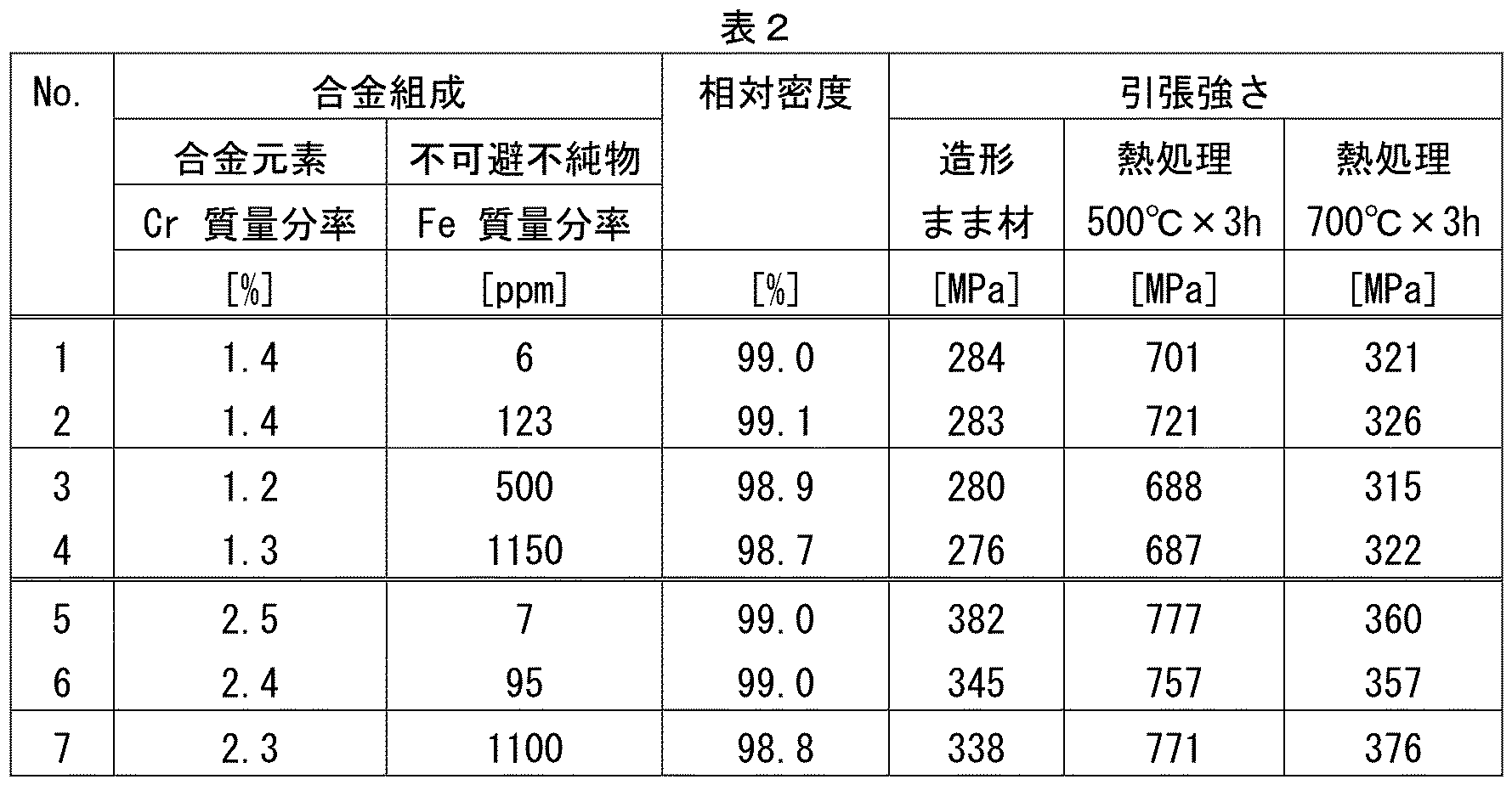
積層造形物として、円柱材(直径 14mm×高さ 15mm)と、ダンベル状試験片(図1参照)とが製造された。円柱材(造形まま材)において、導電率、相対密度が測定された。ダンベル状試験片(造形まま材)において、引張強さが測定された。測定結果は、下記表1、2に示される。 As additive manufacturing objects, cylindrical materials (diameter 14 mm × height 15 mm) and dumbbell-shaped test pieces (see Figure 1) were manufactured. The electrical conductivity and relative density of the cylindrical materials (as-formed materials) were measured. The tensile strength of the dumbbell-shaped test pieces (as-formed materials) was measured. The measurement results are shown in Tables 1 and 2 below.
《(D)熱処理》
熱処理炉において、造形まま材に対して、熱処理が施されることにより、熱処理材が製造された。熱処理炉内の雰囲気は、窒素雰囲気であった。下記表1、2中、例えば「500℃×3h」は、加熱温度が500℃であり、熱処理時間が3時間であることを示す。熱処理材において、導電率、引張強さが測定された。測定結果は下記表1、2に示される。
(D) Heat Treatment
In a heat treatment furnace, the as-shaped material was subjected to heat treatment to produce a heat-treated material. The atmosphere in the heat treatment furnace was a nitrogen atmosphere. In Tables 1 and 2 below, for example, "500°C x 3h" indicates that the heating temperature was 500°C and the heat treatment time was 3 hours. The electrical conductivity and tensile strength of the heat-treated material were measured. The measurement results are shown in Tables 1 and 2 below.

<結果>
Feの質量分率が低減する程、熱処理材の導電率が改善する傾向がみられる(例えば、上記表1の「熱処理 700℃×3h」の欄、図2参照)。
<Results>
There is a tendency that the electrical conductivity of the heat-treated material improves as the mass fraction of Fe decreases (see, for example, the column "
熱処理時の加熱温度が500℃以上である時、導電率の改善幅が大きくなる傾向がみられる。加熱温度が700℃である時、導電率が顕著に改善している(図3、4参照)。 When the heating temperature during heat treatment is 500°C or higher, there is a tendency for the improvement in electrical conductivity to be greater. When the heating temperature is 700°C, the electrical conductivity improves significantly (see Figures 3 and 4).
図5は、銅合金粉末中のFeの質量分率と、積層造形物(熱処理材)の引張強さとの関係を示すグラフである。Feの質量分率と引張強さとの間には、明確な相関がみられない。 Figure 5 is a graph showing the relationship between the mass fraction of Fe in the copper alloy powder and the tensile strength of the additive manufacturing product (heat-treated material). There is no clear correlation between the mass fraction of Fe and the tensile strength.
加熱温度が500℃である時、引張強さが特に良好である(上記表2参照)。 The tensile strength is particularly good when the heating temperature is 500°C (see Table 2 above).
<付記>
1.本技術は、銅合金粉末の使用も提供する。
銅合金粉末の使用は、エネルギービームの照射によって原料粉末が固化される積層造形法における、銅合金粉末の使用である。銅合金粉末は原料粉末として使用される。銅合金粉末は、質量分率で0.1%~20%のクロムと、不可避不純物と、残部の銅とからなる。不可避不純物は鉄を含む。鉄の質量分率は150ppm未満である。銅合金粉末は、質量分率で、例えば1%~2.8%のクロムを含んでいてもよい。
<Additional Notes>
1. The present technology also provides for the use of copper alloy powder.
The use of the copper alloy powder is a use of the copper alloy powder in an additive manufacturing method in which a raw material powder is solidified by irradiation with an energy beam. The copper alloy powder is used as a raw material powder. The copper alloy powder is composed of 0.1% to 20% by mass of chromium, unavoidable impurities, and the balance being copper. The unavoidable impurities include iron. The mass fraction of iron is less than 150 ppm. The copper alloy powder may contain, for example, 1% to 2.8% by mass of chromium.
2.本技術は、銅合金粉末の使用方法も提供する。
銅合金粉末の使用方法は、下記ステップを含む。
・銅合金粉末を準備する。
・エネルギービームの照射によって原料粉末が固化される積層造形法において、積層造形物の原料粉末として銅合金粉末を使用する。
銅合金粉末は、質量分率で0.1%~20%のクロムと、不可避不純物と、残部の銅とからなる。不可避不純物は鉄を含む。鉄の質量分率は150ppm未満である。銅合金粉末は、質量分率で、例えば1%~2.8%のクロムを含んでいてもよい。
2. The present technology also provides a method of using the copper alloy powder.
A method for using the copper alloy powder includes the following steps.
Prepare copper alloy powder.
In the additive manufacturing method, in which raw material powder is solidified by irradiation with an energy beam, copper alloy powder is used as the raw material powder for the additive manufacturing object.
The copper alloy powder is composed of 0.1% to 20% by mass of chromium, unavoidable impurities, and the balance being copper. The unavoidable impurities include iron. The mass fraction of iron is less than 150 ppm. The copper alloy powder may contain, for example, 1% to 2.8% by mass of chromium.
3.例えば、下記式(α)の関係を満たす積層造形物を製造するために、銅合金粉末が使用されてもよい。
Y>92-1.14×10⁻²X …(α)
上記式(α)中、「X」は、Feの質量分率[ppm]を示す。「X」は「0<X<150」の関係を満たす。「Y」は、積層造形物の導電率[%IACS]を示す。
3. For example, a copper alloy powder may be used to manufacture an additive manufacturing object that satisfies the relationship of the following formula (α):
Y>92-1.14× 10⁻² X … (α)
In the above formula (α), "X" represents the mass fraction of Fe [ppm]. "X" satisfies the relationship "0<X<150". "Y" represents the electrical conductivity [% IACS] of the layered object.
4.例えば、下記式(β)の関係を満たす積層造形物を製造するために、銅合金粉末が使用されてもよい。
92-1.14×10⁻²X<Y<96-1.14×10⁻²X …(β)
上記式(β)中、「X」は、Feの質量分率[ppm]を示す。「X」は「0<X<150」の関係を満たす。「Y」は、積層造形物の導電率[%IACS]を示す。
4. For example, a copper alloy powder may be used to manufacture an additive manufacturing object that satisfies the relationship of the following formula (β):
92-1.14× 10⁻² X<Y<96-1.14× 10⁻² X … (β)
In the above formula (β), "X" represents the mass fraction of Fe [ppm]. "X" satisfies the relationship of "0<X<150". "Y" represents the electrical conductivity [% IACS] of the layered object.
5.積層造形物の製造方法は、例えば、上記式(α)または(β)の関係が満たされるように、積層造形物を製造することを含んでいてもよい。 5. The method for manufacturing an additively manufactured object may include, for example, manufacturing an additively manufactured object so that the relationship of formula (α) or (β) above is satisfied.
本実施形態および本実施例は、全ての点で例示である。本実施形態および本実施例は、制限的ではない。本技術の範囲は、特許請求の範囲の記載と均等の意味および範囲内における全ての変更を包含する。例えば、本実施形態および本実施例から、任意の構成が抽出され、それらが任意に組み合わされることも当初から予定されている。 The present embodiment and the present examples are illustrative in all respects. The present embodiment and the present examples are not limiting. The scope of the present technology includes all modifications within the meaning and scope equivalent to the description of the claims. For example, it is intended from the beginning that any configuration may be extracted from the present embodiment and the present examples and that they may be combined in any desired manner.
1 粉末床、2 造形層、10 積層造形物、20 ダンベル状試験片、21 平行部、22 つかみ部、23 肩部、100 積層造形装置、101 ピストン、102 テーブル、103 出力部。 1 Powder bed, 2 Modeling layer, 10 Layered object, 20 Dumbbell-shaped test piece, 21 Parallel part, 22 Grip part, 23 Shoulder part, 100 Layered modeling device, 101 Piston, 102 Table, 103 Output part.
Claims (15)
質量分率で0.1%~20%のクロムと、
不可避不純物と、
残部の銅と、
からなり、
前記不可避不純物は鉄を含み、
鉄の質量分率は150ppm未満である、
銅合金粉末。 A copper alloy powder used as a raw material powder in an additive manufacturing method in which a raw material powder is solidified by irradiation with an energy beam,
0.1% to 20% by mass of chromium;
Inevitable impurities,
The balance is copper,
It consists of:
The inevitable impurities include iron,
The mass fraction of iron is less than 150 ppm;
Copper alloy powder.
請求項1に記載の銅合金粉末。 The mass fraction of iron is less than 100 ppm;
The copper alloy powder according to claim 1.
請求項2に記載の銅合金粉末。 The mass fraction of iron is less than 60 ppm;
The copper alloy powder according to claim 2.
請求項3に記載の銅合金粉末。 The mass fraction of iron is less than 10 ppm;
The copper alloy powder according to claim 3.
請求項1から請求項4のいずれか1項に記載の銅合金粉末。 The energy beam includes at least one selected from the group consisting of a laser, an electron beam, and a plasma.
The copper alloy powder according to any one of claims 1 to 4.
前記銅合金粉末を固化することにより、造形層を形成すること、
および、
前記造形層を複数積層することにより、積層造形物を製造すること、
を含む、
積層造形物の製造方法。 Providing a copper alloy powder according to any one of claims 1 to 4;
forming a modeling layer by solidifying the copper alloy powder;
and,
Manufacturing a layered object by stacking a plurality of the modeling layers;
including,
A method for manufacturing an additively manufactured object.
をさらに含む、
請求項6に記載の積層造形物の製造方法。 subjecting the layered object to a heat treatment;
Further comprising:
The method for producing a layered object according to claim 6 .
請求項7に記載の積層造形物の製造方法。 The heating temperature in the heat treatment is 500° C. or higher.
The method for producing a layered object according to claim 7 .
請求項8に記載の積層造形物の製造方法。 The heating temperature is 700° C. or less.
The method for producing a layered object according to claim 8 .
不可避不純物と、
残部の銅と、
からなり、
前記不可避不純物は鉄を含み、
鉄の質量分率は150ppm未満である、
積層造形物。 0.1% to 20% by mass of chromium;
Inevitable impurities,
The balance is copper,
It consists of:
The inevitable impurities include iron,
The mass fraction of iron is less than 150 ppm;
Additive manufacturing.
請求項10に記載の積層造形物。 The mass fraction of iron is less than 100 ppm;
The layered object according to claim 10.
請求項11に記載の積層造形物。 The mass fraction of iron is less than 60 ppm;
The layered object according to claim 11.
請求項12に記載の積層造形物。 The mass fraction of iron is less than 10 ppm;
The layered object according to claim 12.
請求項10から請求項13のいずれか1項に記載の積層造形物。 A relative density of 97% to 100% of the theoretical density.
The layered object according to any one of claims 10 to 13.
請求項10から請求項13のいずれか1項に記載の積層造形物。
Has a conductivity of 90% IACS or more;
The layered object according to any one of claims 10 to 13.
Priority Applications (1)
| Application Number | Priority Date | Filing Date | Title |
|---|---|---|---|
| JP2022176135A JP2024066625A (en) | 2022-11-02 | 2022-11-02 | Copper alloy powder, method for manufacturing laminated object, and laminated object |
Applications Claiming Priority (1)
| Application Number | Priority Date | Filing Date | Title |
|---|---|---|---|
| JP2022176135A JP2024066625A (en) | 2022-11-02 | 2022-11-02 | Copper alloy powder, method for manufacturing laminated object, and laminated object |
Publications (1)
| Publication Number | Publication Date |
|---|---|
| JP2024066625A true JP2024066625A (en) | 2024-05-16 |
Family
ID=91067469
Family Applications (1)
| Application Number | Title | Priority Date | Filing Date |
|---|---|---|---|
| JP2022176135A Pending JP2024066625A (en) | 2022-11-02 | 2022-11-02 | Copper alloy powder, method for manufacturing laminated object, and laminated object |
Country Status (1)
| Country | Link |
|---|---|
| JP (1) | JP2024066625A (en) |
-
2022
- 2022-11-02 JP JP2022176135A patent/JP2024066625A/en active Pending
Similar Documents
| Publication | Publication Date | Title |
|---|---|---|
| JP7630554B2 (en) | Copper alloy powder, laminated object, manufacturing method for laminated object, and various metal parts | |
| KR102722473B1 (en) | Aluminum alloy parts manufacturing process | |
| WO2018079304A1 (en) | Copper alloy powder, laminate molding production method, and laminate molding | |
| US10576538B2 (en) | Alloy structure and method for producing alloy structure | |
| JP6803021B2 (en) | Manufacturing method of laminated model and laminated model | |
| US20170209954A1 (en) | Alloy structure and method for producing alloy structure | |
| JP2021514423A (en) | Manufacturing method of aluminum / chrome alloy parts | |
| KR102239261B1 (en) | Copper alloy powder, manufacturing method of laminated moldings and laminated moldings | |
| JP7386819B2 (en) | Method for manufacturing parts made of aluminum alloy | |
| JP7626286B2 (en) | Manufacturing method of copper alloy powder for metal AM | |
| US12528125B2 (en) | Method for manufacturing an aluminum alloy part | |
| WO2017203717A1 (en) | Laminate-molding metal powder, laminate-molded article manufacturing method, and laminate-molded article | |
| KR20200096657A (en) | Use of aluminum-containing alloys for lamination molding | |
| JP2025020372A (en) | Copper alloy powder for metal AM and method for manufacturing laminated objects | |
| JP7524547B2 (en) | Cr-Ni alloy member and manufacturing method thereof | |
| JP2024066625A (en) | Copper alloy powder, method for manufacturing laminated object, and laminated object | |
| JP7678686B2 (en) | Shaped body made of Cu-based alloy | |
| JP7586376B2 (en) | Metal AM copper alloy powder and method for manufacturing laminated objects | |
| JP2019035134A (en) | Copper alloy powder for laminate molding, method for producing laminate molding and laminate molding | |
| JP2024156538A (en) | Copper alloy powder, laminated object using same, and copper alloy molded object made of laminated object | |
| JP7563652B2 (en) | Copper alloy powder for metal AM and method for manufacturing laminated objects | |
| JP7513224B1 (en) | Copper alloy powder for metal AM and method for manufacturing laminated objects | |
| JP2025056621A (en) | Low thermal expansion laminated alloy | |
| WO2025100263A1 (en) | Aluminum alloy molded body and method for producing same | |
| KR20250029188A (en) | Copper alloy powder for laminated molding, copper alloy laminated molding body and method for manufacturing copper alloy laminated molding body |
Legal Events
| Date | Code | Title | Description |
|---|---|---|---|
| A621 | Written request for application examination |
Free format text: JAPANESE INTERMEDIATE CODE: A621 Effective date: 20251020 |