JP2023177687A - Heater drive control device, electronic component handling device, electronic component testing device, and heater drive control method - Google Patents
Heater drive control device, electronic component handling device, electronic component testing device, and heater drive control method Download PDFInfo
- Publication number
- JP2023177687A JP2023177687A JP2022090485A JP2022090485A JP2023177687A JP 2023177687 A JP2023177687 A JP 2023177687A JP 2022090485 A JP2022090485 A JP 2022090485A JP 2022090485 A JP2022090485 A JP 2022090485A JP 2023177687 A JP2023177687 A JP 2023177687A
- Authority
- JP
- Japan
- Prior art keywords
- heaters
- control device
- drive control
- heater
- chamber
- Prior art date
- Legal status (The legal status is an assumption and is not a legal conclusion. Google has not performed a legal analysis and makes no representation as to the accuracy of the status listed.)
- Pending
Links
Images


Classifications
-
- G—PHYSICS
- G01—MEASURING; TESTING
- G01R—MEASURING ELECTRIC VARIABLES; MEASURING MAGNETIC VARIABLES
- G01R31/00—Arrangements for testing electric properties; Arrangements for locating electric faults; Arrangements for electrical testing characterised by what is being tested not provided for elsewhere
- G01R31/28—Testing of electronic circuits, e.g. by signal tracer
- G01R31/2851—Testing of integrated circuits [IC]
- G01R31/2855—Environmental, reliability or burn-in testing
- G01R31/2872—Environmental, reliability or burn-in testing related to electrical or environmental aspects, e.g. temperature, humidity, vibration, nuclear radiation
- G01R31/2874—Environmental, reliability or burn-in testing related to electrical or environmental aspects, e.g. temperature, humidity, vibration, nuclear radiation related to temperature
- G01R31/2875—Environmental, reliability or burn-in testing related to electrical or environmental aspects, e.g. temperature, humidity, vibration, nuclear radiation related to temperature related to heating
-
- G—PHYSICS
- G01—MEASURING; TESTING
- G01R—MEASURING ELECTRIC VARIABLES; MEASURING MAGNETIC VARIABLES
- G01R19/00—Arrangements for measuring currents or voltages or for indicating presence or sign thereof
- G01R19/10—Measuring sum, difference or ratio
-
- G—PHYSICS
- G01—MEASURING; TESTING
- G01R—MEASURING ELECTRIC VARIABLES; MEASURING MAGNETIC VARIABLES
- G01R19/00—Arrangements for measuring currents or voltages or for indicating presence or sign thereof
- G01R19/165—Indicating that current or voltage is either above or below a predetermined value or within or outside a predetermined range of values
- G01R19/16566—Circuits and arrangements for comparing voltage or current with one or several thresholds and for indicating the result not covered by subgroups G01R19/16504, G01R19/16528, G01R19/16533
- G01R19/16571—Circuits and arrangements for comparing voltage or current with one or several thresholds and for indicating the result not covered by subgroups G01R19/16504, G01R19/16528, G01R19/16533 comparing AC or DC current with one threshold, e.g. load current, over-current, surge current or fault current
-
- G—PHYSICS
- G01—MEASURING; TESTING
- G01R—MEASURING ELECTRIC VARIABLES; MEASURING MAGNETIC VARIABLES
- G01R31/00—Arrangements for testing electric properties; Arrangements for locating electric faults; Arrangements for electrical testing characterised by what is being tested not provided for elsewhere
- G01R31/28—Testing of electronic circuits, e.g. by signal tracer
- G01R31/2851—Testing of integrated circuits [IC]
- G01R31/2855—Environmental, reliability or burn-in testing
- G01R31/286—External aspects, e.g. related to chambers, contacting devices or handlers
- G01R31/2862—Chambers or ovens; Tanks
-
- G—PHYSICS
- G05—CONTROLLING; REGULATING
- G05D—SYSTEMS FOR CONTROLLING OR REGULATING NON-ELECTRIC VARIABLES
- G05D23/00—Control of temperature
- G05D23/19—Control of temperature characterised by the use of electric means
- G05D23/1917—Control of temperature characterised by the use of electric means using digital means
-
- H—ELECTRICITY
- H05—ELECTRIC TECHNIQUES NOT OTHERWISE PROVIDED FOR
- H05B—ELECTRIC HEATING; ELECTRIC LIGHT SOURCES NOT OTHERWISE PROVIDED FOR; CIRCUIT ARRANGEMENTS FOR ELECTRIC LIGHT SOURCES, IN GENERAL
- H05B1/00—Details of electric heating devices
- H05B1/02—Automatic switching arrangements specially adapted to apparatus ; Control of heating devices
- H05B1/0227—Applications
- H05B1/023—Industrial applications
-
- H—ELECTRICITY
- H05—ELECTRIC TECHNIQUES NOT OTHERWISE PROVIDED FOR
- H05B—ELECTRIC HEATING; ELECTRIC LIGHT SOURCES NOT OTHERWISE PROVIDED FOR; CIRCUIT ARRANGEMENTS FOR ELECTRIC LIGHT SOURCES, IN GENERAL
- H05B3/00—Ohmic-resistance heating
- H05B3/0019—Circuit arrangements
-
- H—ELECTRICITY
- H05—ELECTRIC TECHNIQUES NOT OTHERWISE PROVIDED FOR
- H05B—ELECTRIC HEATING; ELECTRIC LIGHT SOURCES NOT OTHERWISE PROVIDED FOR; CIRCUIT ARRANGEMENTS FOR ELECTRIC LIGHT SOURCES, IN GENERAL
- H05B2203/00—Aspects relating to Ohmic resistive heating covered by group H05B3/00
- H05B2203/002—Heaters using a particular layout for the resistive material or resistive elements
- H05B2203/007—Heaters using a particular layout for the resistive material or resistive elements using multiple electrically connected resistive elements or resistive zones
Landscapes
- Engineering & Computer Science (AREA)
- Physics & Mathematics (AREA)
- General Physics & Mathematics (AREA)
- Environmental & Geological Engineering (AREA)
- Computer Hardware Design (AREA)
- Microelectronics & Electronic Packaging (AREA)
- General Engineering & Computer Science (AREA)
- Toxicology (AREA)
- Health & Medical Sciences (AREA)
- Automation & Control Theory (AREA)
- Power Engineering (AREA)
- Control Of Temperature (AREA)
- Control Of Resistance Heating (AREA)
- Testing Of Individual Semiconductor Devices (AREA)
Abstract
【課題】電源系統を最適化できると共に、電気系統を有効活用を図ることが可能なヒータ駆動制御装置を提供する。【解決手段】ヒータ駆動制御装置30は、第1~第3のヒータ22a~26cが内部に設けられたテストチャンバ21、ソークチャンバ23、及び、アンソークチャンバ25を備えた電子部品試験装置1に用いられる。ヒータ駆動制御装置30は、電源40から各々のヒータ22a~26cに入力される電流を制御する制御装置32と、電源40と複数のヒータ22a~26cとの間に配置されたブレーカ31と、を備えている。制御装置32は、複数のヒータに対して設定された第1のプライオリティに応じて、複数のヒータ22a~26cに供給する電流の和がブレーカ31の定格電流の範囲内となるように、複数のヒータ22a~26cに順に電流を供給する第1の駆動制御を実行する。【選択図】図1The present invention provides a heater drive control device capable of optimizing a power supply system and effectively utilizing the electric system. A heater drive control device 30 is installed in an electronic component testing apparatus 1 equipped with a test chamber 21, a soak chamber 23, and an unsoak chamber 25 in which first to third heaters 22a to 26c are provided. used. The heater drive control device 30 includes a control device 32 that controls the current input from a power source 40 to each of the heaters 22a to 26c, and a breaker 31 disposed between the power source 40 and the plurality of heaters 22a to 26c. We are prepared. The control device 32 controls the plurality of heaters so that the sum of the currents supplied to the plurality of heaters 22a to 26c is within the range of the rated current of the breaker 31 according to the first priority set for the plurality of heaters. First drive control is executed to sequentially supply current to the heaters 22a to 26c. [Selection diagram] Figure 1
Description
本発明は、半導体集積回路素子等の被試験電子部品(DUT:Device Under Test)の試験を行う電子部品試験装置に設けられたヒータの駆動を制御するヒータ駆動制御装置、ヒータ駆動制御装置を備える電子部品ハンドリング装置及び電子部品試験装置、並びに、ヒータ駆動制御方法に関するものである。 The present invention includes a heater drive control device and a heater drive control device that control the drive of a heater provided in an electronic component testing device that tests electronic components under test (DUT: Device Under Test) such as semiconductor integrated circuit elements. The present invention relates to an electronic component handling device, an electronic component testing device, and a heater drive control method.
電子部品試験装置は、チャンバ部を備えている(例えば、特許文献1参照)。このチャンバ部は、ソークチャンバと、テストチャンバと、アンソークチャンバと、を含んでいる。ソークチャンバは、テストトレイに積み込まれたDUTに目的とする高温又は低温の熱ストレスを印加する恒温槽である。テストチャンバは、ソークチャンバで熱ストレスが印加された状態にあるDUTをテストヘッドに接触させる測定部である。アンソークチャンバは、測定部で試験されたDUTから、印加された熱ストレスを除去する除熱槽である。 The electronic component testing device includes a chamber section (for example, see Patent Document 1). The chamber section includes a soak chamber, a test chamber, and an unsoak chamber. The soak chamber is a constant temperature bath that applies a desired high or low temperature thermal stress to the DUTs loaded on the test tray. The test chamber is a measurement unit that brings the DUT, which has been subjected to thermal stress in the soak chamber, into contact with the test head. The unsoak chamber is a heat removal tank that removes the applied thermal stress from the DUT tested in the measurement section.
上記の電子部品試験装置におけるチャンバ部では、一般的に、各チャンバの内部の温度を調整するための複数のヒータが設けられている。しかしながら、各チャンバの内部の温度を目標温度とするために複数のヒータを同時にオンすると、各ヒータに供給する電流の和の最大値(ピーク電流)が大きくなる。これに対応するためには、ブレーカの定格電流を大きくする必要があり、ブレーカ等の電源系統が大型化してしまう。 The chamber section of the electronic component testing apparatus described above is generally provided with a plurality of heaters for adjusting the temperature inside each chamber. However, when a plurality of heaters are simultaneously turned on in order to set the internal temperature of each chamber to the target temperature, the maximum value (peak current) of the sum of currents supplied to each heater becomes large. In order to cope with this, it is necessary to increase the rated current of the breaker, which increases the size of the power supply system such as the breaker.
一方で、各チャンバの内部を目標温度まで昇温した後において、目標温度を維持するために要する電流は昇温時に要する電流と比較すると小さいので、電子部品試験装置の稼働時間の大部分において電源系統を有効活用できていない。 On the other hand, after heating the inside of each chamber to the target temperature, the current required to maintain the target temperature is small compared to the current required during temperature rise, so the power supply is used for most of the operating time of the electronic component test equipment. The system cannot be used effectively.
本発明が解決しようとする課題は、電源系統のサイズを最適化できると共に、電気系統の有効活用を図ることが可能なヒータ駆動制御装置、電子部品ハンドリング装置、電子部品試験装置、及び、ヒータ駆動制御方法を提供することである。 The problem to be solved by the present invention is to provide a heater drive control device, an electronic component handling device, an electronic component testing device, and a heater drive control device that can optimize the size of a power supply system and make effective use of the electrical system. The object of the present invention is to provide a control method.
[1]本発明の態様1は、複数のヒータが内部に設けられたテストチャンバ、ソークチャンバ、及び、アンソークチャンバを備えた電子部品試験装置に用いられるヒータ駆動制御装置であって、前記ヒータ駆動制御装置は、電源から各々の前記ヒータに供給される電流を制御する制御装置と、前記電源と前記複数のヒータとの間に配置されたブレーカと、を備え、前記制御装置は、前記複数のヒータに供給する電流の和が前記ブレーカの定格電流の範囲内となるように、前記複数のヒータに対して設定された第1のプライオリティに応じて、前記複数のヒータに順に電流を供給する第1の駆動制御を実行するヒータ駆動制御装置である。
[1]
[2]本発明の態様2は、態様1のヒータ駆動制御装置において、前記制御装置は、所定のサイクルで前記複数のヒータを制御しており、前記サイクル毎に、前記定格電流と、オン状態とする前記複数のヒータの電力から算出された線電流の和と、を比較し、前記線電流の和が前記定格電流よりも大きい場合に、前記第1の駆動制御を実行してもよい。
[2]
[3]本発明の態様3は、態様2のヒータ駆動制御装置において、前記電源は三相交流電源であり、前記線電流は、三相の線電流IR,IS,ITから構成されており、前記制御装置は、前記第1の駆動制御において、前記線電流IR,IS,ITがバランスするように前記複数のヒータに順に電流を供給してもよい。
[3]
[4]本発明の態様4は、態様1~態様3のいずれか一つのヒータ駆動制御装置において、前記第1のプライオリティは、前記テストチャンバ、前記ソークチャンバ、及び、前記アンソークチャンバ毎に設定された第2のプライオリティに基づいて設定されていてもよい。
[4] Aspect 4 of the present invention is that in the heater drive control device according to any one of
[5]本発明の態様5は、態様1~4のいずれか一つのヒータ駆動制御装置において、前記制御装置は、前記第1のプライオリティを変更可能な変更部を備え、前記電子部品試験装置は、前記テストチャンバ、前記ソークチャンバ、及び、前記アンソークチャンバを備えたコンタクトユニットを複数備え、前記変更部は、前記第1のプライオリティを、前記コンタクトユニット毎に設定された第3のプライオリティに基づいて変更してもよい。
[5]
[6]本発明の態様6は、態様1~5のいずれか一つのヒータ駆動制御装置において、前記制御装置は、前記第1のプライオリティを変更可能な変更部と、前記テストチャンバ、前記ソークチャンバ、及び、前記アンソークチャンバの内部に設けられた複数の温度センサと、を備え、前記制御装置は、前記温度センサが検出した前記テストチャンバ、前記ソークチャンバ、及び、前記アンソークチャンバの内部の検出温度と、目標温度と、の温度差を算出し、前記変更部は、前記第1のプライオリティを前記温度差に応じて変更してもよい。
[6] Aspect 6 of the present invention is the heater drive control device according to any one of
[7]本発明の態様7は、態様1~6のいずれか一つのヒータ駆動制御装置において、前記複数のヒータは、第1のヒータと、前記第1のヒータよりも前記第1のプライオリティが低く設定されている第2のヒータと、を含んでおり、前記制御装置は、前記第1の駆動制御において、前記第1のヒータに電流を供給し、前記第1のヒータへ供給する電流を減じてから、前記第2のヒータへ電流を供給してもよい。
[7] Aspect 7 of the present invention is the heater drive control device according to any one of
[8]本発明の態様8は、態様1~7のいずれか一つのヒータ駆動制御装置を備える電子部品ハンドリング装置である。
[8] Aspect 8 of the present invention is an electronic component handling device including the heater drive control device according to any one of
[9]本発明の態様9は、態様1~7のいずれか一つのヒータ駆動制御装置を備える電子部品試験装置である。 [9] A ninth aspect of the present invention is an electronic component testing apparatus including the heater drive control device according to any one of the first to seventh aspects.
[10]本発明の態様10は、電子部品試験装置のテストチャンバ、ソークチャンバ、及び、アンソークチャンバの内部に設けられた複数のヒータの駆動を制御するヒータ駆動制御方法であって、前記複数のヒータに供給する電流の和がブレーカの定格電流の範囲内となるように、前記複数のヒータに対して設定された第1のプライオリティに応じて、前記複数のヒータに順に電流を供給する第1の駆動制御工程を備えるヒータ駆動制御方法である。
[10]
本発明によれば、制御装置が複数のヒータに対して設定された第1のプライオリティに応じて、複数のヒータに供給する電流の和がブレーカの定格電流の範囲内となるように、複数のヒータに順に電流を供給する第1の駆動制御を実行するので、電源系統を最適化できると共に、電気系統の有効活用を図ることができる。 According to the present invention, the control device controls the plurality of heaters according to the first priority set for the plurality of heaters so that the sum of the currents supplied to the plurality of heaters is within the range of the rated current of the breaker. Since the first drive control in which current is sequentially supplied to the heaters is executed, the power supply system can be optimized and the electric system can be used effectively.
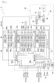
以下、本発明の実施形態を図面に基づいて説明する。図1は、本実施形態における電子部品試験装置1の一例を示すブロック図である。
Embodiments of the present invention will be described below based on the drawings. FIG. 1 is a block diagram showing an example of an electronic
本実施形態における電子部品試験装置1は、DUT(不図示)に高温又は低温の熱ストレスを印加した状態(或いは常温の状態)でDUTの電気的特性を試験し、その試験結果に応じてDUTを分類する装置である。試験対象であるDUTの具体例としては、特に限定されないが、メモリ系のデバイス、ロジック系のデバイス、及び、SoC(System on a chip)等を例示することができる。
The electronic
電子部品試験装置1は、テストヘッド5と、ハンドラ10と、ヒータ駆動制御装置30と、を備えている。本実施形態におけるハンドラ10は、本発明の態様における「電子部品ハンドリング装置」の一例に相当する。
The electronic
テストヘッド5は、DUTと、DUTの試験を実行するテスタ(不図示)と、を電気的に接続する部分である。このテストヘッド5はソケット(不図示)を備えており、このソケットがDUTと接触することで、DUTとテスタが電気的に接続される。このようなテストヘッド5としては、特に限定されないが、具体的には、特開2022-21239号公報に記載のテストヘッドや、特開2014-016258号公報に記載のテストヘッド等を例示することができる。
The
ハンドラ10は、コンタクトユニット20を備えている。このコンタクトユニット20は、DUTをテストヘッド5と接触させる接触位置まで搬送すると共に、試験後のDUTを接触位置から退避させる装置である。また、このコンタクトユニット20は、DUTの温度を適切な温度に調整する。このようなコンタクトユニット20として、特に限定されないが、具体的には、特開2022-21239号公報に記載のコンタクトユニットを例示することができる。
The
なお、特に図示しないが、ハンドラ10は、コンタクトユニット20にDUTを搬送するロードユニット、及び、コンタクトユニット20から試験後のDUTを搬出するアンロードユニット等も備えている。
Although not particularly shown, the
このコンタクトユニット20は、ソークチャンバ21と、第1のヒータ22a~22fと、テストチャンバ23と、第2のヒータ24a~24hと、アンソークチャンバ25と、第3のヒータ26a~26dと、を備えている。上述の特開2022-21239号公報に記載のコンタクトユニットでは、各チャンバが垂直方向に沿って並べられているがこれに限定されず、特開2014-016258号公報に記載されたハンドラのように、各チャンバが水平方向に沿って並べられていてもよい。
This
ソークチャンバ21は、試験前のDUTを予熱するための恒温槽である。なお、予熱とはDUTに温熱を与えることでDUTを加熱することのみを意味しておらず、DUTに冷熱を与えることによりDUTを冷却することも予熱に含まれる。
The
このソークチャンバ21の内部に、複数(本例では6個)の第1のヒータ22a~22fが設けられている。第1のヒータ22a~22fは、ソークチャンバ21の内部の温度を予熱に必要な温度である第1の目標温度に調整する。詳細については後述するが、本実施形態では、第1のヒータ22a~22fは、同一のタイミングでオフからオンに切り替えられるわけではなく、順にオンに切り替えられる。
Inside this soak
テストチャンバ23は、DUTの温度を試験温度である第2の目標温度に維持するための恒温槽である。ソークチャンバ21において予熱された後のDUTは、テストチャンバ23に搬送される。このテストチャンバ23の内部にテストヘッド5のソケット近傍の部分が収容されており、テストチャンバ23の内部でDUTはソケットと接触し、DUTが所定の温度条件下で試験される。なお、ソークチャンバ21とテストチャンバ23とが1個のチャンバから構成されていてもよい。
The
このテストチャンバ23の内部に、複数(本例では8個)の第2のヒータ24a~24hが設けられている。第2のヒータ24a~24hは、テストチャンバ23の内部の温度を第2の目標温度に調整する。本実施形態では、第2のヒータ24a~24hも、同一のタイミングでオフからオンに切り替えられるわけではなく、順にオンに切り替えられる。
Inside this
アンソークチャンバ25は、試験後のDUTを除熱するための恒温槽である。なお、除熱とはDUTに冷熱を与えることでDUTの温度を下げて常温とすることのみを意味しておらず、DUTに温熱を与えることによりDUTの温度を上げて常温とすること(つまり、冷熱を除くこと)も除熱に含まれる。
The
このアンソークチャンバ25の内部に、複数(本例では4個)の第3のヒータ26a~26dが設けられている。第3のヒータ26a~26dは、アンソークチャンバ25の内部の温度を除熱に必要となる第3の目標温度に調整する。本実施形態では、第3のヒータ26a~26dも、同一のタイミングでオフからオンに切り替えられるわけではなく、順にオンに切り替えられる。
Inside this
なお、第1~第3のヒータ22a~26cの個数は特に限定されず、コンタクトユニット20の設計に応じて変更される。
Note that the number of the first to
ヒータ駆動制御装置30は、ブレーカ部31と、制御装置32と、を備えている。本実施形態におけるブレーカ部31は、メインブレーカ(BCU)31aと、分岐ブレーカ(ACU)31b1,31b2と、第1の配線群311aと、第2の配線群311bと、を含んでいる。
The heater
メインブレーカ31aは、電源40と電気的に接続されている。電源40は、三相交流電源であり、メインブレーカ31aに向かって、3相の線電流IR,IS,ITを流すことができる。このメインブレーカ31aは所定の定格電流を有しており、電源40から供給される線電流IR,IS,ITの電流値の和(IR+IS+IT)は、メインブレーカ31aの定格電流以下に制限される。
メインブレーカ31aに分岐ブレーカ31bが電気的に接続している。分岐ブレーカ31bにより、メインブレーカ31aから供給される線電流は2系統に分配されており、第1の配線群311a又は第2の配線群311bに線電流が分配される。この分岐ブレーカ31bは、第1の配線群311aに対する所定の定格電流と、第2の配線群311bに対する所定の定格電流を有している。
A
この分岐ブレーカ31bは、後述する第1のヒータドライバボード(HTDB)36a及び第2のヒータドライバボード(HTDB)36bと電気的に接続しており、分配された線電流は第1のHTDB36a又は第2のHTDB36bに供給される。
This
第1の配線群311aは、分岐ブレーカ31bと第1のHTDB36aとの間に介在しており、分岐ブレーカ31bと第1のHTDB36aとを電気的に接続している。本実施形態における第1の配線群311aは、線電流IRを流すための配線311arと、線電流ISを流すための配線311asと、線電流ITを流すための配線311atと、を含んでいる。
The
同様に、第2の配線群311bは、分岐ブレーカ31bと第2のHTDB36bとの間に介在しており、分岐ブレーカ31bと第2のHTDB36bとを電気的に接続している。本実施形態における第2の配線群bは、線電流IRを流すための配線311brと、線電流ISを流すための配線311bsと、線電流ITを流すための配線311btと、を含んでいる。
Similarly, the second wiring group 311b is interposed between the
図2は、本実施形態における制御装置32の一例を示すブロック図である。図2に示すように、制御装置32は、電源40から第1~第3のヒータ22a~26dに供給される電流を制御する。第1~第3のヒータ22a~26dに供給する電流の和がブレーカ31の定格電流の範囲内となるように、第1~第3のヒータ22a~26dに対して設定された第1のプライオリティ(優先度)に応じて、第1~第3のヒータ22a~26dに順に電流を供給する第1の駆動制御を実行する。なお、第1のプライオリティについては後述する。
FIG. 2 is a block diagram showing an example of the
この制御装置32は、PC33と、通信ボード34と、入出力ボード35と、第1及び第2のHTDB36a,36bと、計測ボード37と、複数の温度センサ38(温度センサ群38)と、を備えている。
This
PC33は、例えば、CPU、ROM、及び、RAM等を含むコンピュータであり、特に限定されないが、産業用PC(FAPC)等である。このPC33は、プライオリティ作成部33aと、記憶部33bと、オンオフ制御部33cと、を含んでいる。
The
本実施形態におけるプライオリティ作成部33aは、作業者によって手動で第1のプライオリティを入力される部分である。つまり、作業者は、PC33のユーザインターフェイス等を介して、プライオリティ作成部33aにおいて第1のプライオリティを手動で設定及び変更することができる。このプライオリティ作成部33aは、設定された第1のプライオリティを記憶部33bに出力する。なお、第1のプライオリティは、例えば、PC33にインストールされたソフトウェア等によって自動的に設定及び変更されてもよい。本実施形態の態様におけるプライオリティ作成部33aが、本発明における「変更部」の一例に相当する。
The
記憶部33bは、プライオリティ作成部33aから出力された第1のプライオリティを記憶する。記憶部33bは、既に記憶された既存の第1のプライオリティが存在する場合には、プライオリティ作成部33aから新たに入力された新規の第1のプライオリティを記憶する。この記憶部33bは、オンオフ制御部33cに第1のプライオリティに関する信号を出力する。
The
オンオフ制御部33cは、所定のサイクル(例えば、1ms毎)で第1~第3のヒータ22a~22e,24a~24h,26a~26dをオンオフ制御する。このオンオフ制御部33cは、有線又は無線により通信ボード34と通信することができ、第1のプリオリティに基づいて通信ボード34にオンオフ制御信号を出力する。このオンオフ制御信号は、後述する第1及び第2のHTDB36a,36bのトライアック361bに最終的に入力され、当該トライアック361をオンオフ制御する信号である。
The on/off
このオンオフ制御部33cは、上記のサイクル毎に、メインブレーカ31aの定格電流と、オン状態とする複数のヒータの電力から算出された線電流の和と、を比較する。そして、オンオフ制御部33cは、線電流の和が上記の定格電流よりも大きい場合に、後述する第1の駆動制御を実行する。なお、線電流の和は、後述する相電流から求めることができ、例えばΔ結線においては、相電流をルート3倍することで線電流を求めることができる。
The on/off
なお、本実施形態における制御装置32のPC33のプライオリティ作成部33a、記憶部22b、及びオンオフ制御部33cの機能を、回路基板に組み込まれたCPU等で実現してもよい。
Note that the functions of the
通信ボード34は、PC33、入出力ボード35、及び、計測ボード37と通信可能な回路基板である。通信ボード34は、オンオフ制御部33cから入力されたオンオフ制御信号を入出力ボード35に出力する。また、通信ボード34は、計測ボード37から出力された温度センサ38による検出信号(後述)を受信し、プライオリティ作成部33aに出力することもできる。
The
入出力ボード35は、特に限定されないが、I/O基板である。入出力ボード35は、オンオフ制御信号を第1のHTDB36aと第2のHTDB36bとに伝達する。
The input/
第1のHTDB36aは、第1のヒータ22aと、第2のヒータ24a~24dと、第3のヒータ26a~26cと、に電流を分配供給するドライバボードである。すなわち、各ヒータへ供給する電流の大きさを制御するドライバボードである。
The
図3は、本実施形態における第1のヒータドライバボード36aの一例を示すブロック図である。図4は、本実施形態における電源40、第1の配線群311a、第1のヒータドライバボード36a、及び、第1~第3のヒータ22a,24a~24d,26a~26cの一例を示す回路図である。なお、図4の回路図ではヒューズ361aの図示を省略している。
FIG. 3 is a block diagram showing an example of the first
図3に示すように、本実施形態における第1のHTDB36aは、9個のヒータ22a,24a~24d,26a~26cに対して相電流IRS,IST,ITRを分配する回路基板である。図4に示すように、本実施形態の電源40、第1の配線群311a、第1のヒータドライバボード36a、及び、第1~第3のヒータ22a,24a~24d,26a~26cは、Δ結線を構成している。
As shown in FIG. 3, the
図3に示すように、この第1のHTDB36aは、複数(本例では9個)のヒューズ361aと、各々のヒューズ361aに電気的に接続されたトライアック361b1~361b9(適宜、トライアック361bと総称する)と、を含んでいる。
As shown in FIG. 3, the
ヒューズ361aは、過電流が回路に流れた際に回路を遮断する。特に限定されないが、ヒューズ361aとしては、10Aを超える電流が流れた際に回路を遮断するものを用いることができる。本実施形態では、3個のヒューズ361aが電気的に並列に配置されている。
The
トライアック361bは、ゼロクロス(交流電圧がゼロ)でオンするスイッチである。本実施形態において、トライアック361bは、ヒューズ361aと第1~第3のヒータ22a,24a~24d,26a~26cとの間に介在している。トライアック361bは、上述のオンオフ制御信号によってオンオフ制御される。
The triac 361b is a switch that turns on at zero cross (AC voltage is zero). In this embodiment, the triac 361b is interposed between the
より具体的には、図4に示すように、Δ結線の負荷側のRS間には、相互に電気的に並列に接続されている3個のトライアック361b1~361b3、及び、第2及び第3のヒータ24a,24c,26aが配置されている。Δ結線の負荷側のST間には、相互に電気的に並列に接続されている3個のトライアック361b4~361b6、及び、第1~第3のヒータ22a,24e,26bが配置されている。Δ結線の負荷側のTR間には、相互に電気的に並列に接続されている3個のトライアック361b7~361b9、及び、第2及び第3のヒータ24b,24d,26cが配置されている。
More specifically, as shown in FIG. 4, three triacs 361b 1 to 361b 3 electrically connected in parallel to each other are connected between the RSs on the load side of the Δ connection;
このような回路では、トライアック361bのオンオフ制御によって、電流を供給する第1~第3のヒータ22a,24a~24d,26a~26cを選択できると共に、当該ヒータに供給する電流量を制御できる。なお、電流量の制御は、特に限定されないが、デュティ比を調節することにより制御することができる。
In such a circuit, the first to
また、図1に示す第2のHTDB36bも、基本的に、第1のHTDB36aと同様の構造を有している。この第2のHTDB36bも、電源40と、第2の配線群311bと、第1~第3のヒータ22b~22e,24f~24h,26dと、共にΔ結線を構成している。制御装置32は、入出力ボード35から入力される第1のプライオリティに基づいて、第2のHTDB36bにおけるトライアック361bをオンオフ制御することにより、電流を供給する第1~第3のヒータ22b~22e,24f~24h,26d(図2参照)を選択できると共に、当該ヒータに供給する電流量を制御できる。
Furthermore, the
なお、第1のHTDB36aは、電源40と、第1の配線群311aと、第1~第3のヒータ22b~22e,24f~24h,26dと、共にY結線を構成していてもよい。同様に、第2のHTDB36bも、電源40と第2の配線群311bと、第1~第3のヒータ22b~22e,24f~24h,26dと、共にY結線を構成していてもよい。
Note that the
図2に示すように、計測ボード37は、温度センサ群38からの検出信号を受信する回路基板である。この計測ボード37は、各々の温度センサ群38による検出温度を通信ボード34を介してプライオリティ作成部33aに出力する。
As shown in FIG. 2, the
温度センサ群38は、特に図示しないが、第1~第3のヒータ22a~26dに対応する個数(本例では18個)の温度センサを含んでいる。温度センサ群38を構成している各々の温度センサは、第1~第3のヒータ22a~26dのぞれぞれに対応する位置に配置されており、各ヒータの近傍の温度を検出する。
Although not particularly shown, the
[第1のプライオリティ]
このようなヒータ駆動制御装置30において複数の第1~第3のヒータ22a~26dに対して設定された第1のプライオリティについて図を参照しながら説明する。図5は、本実施形態における第1のプライオリティの設定の一例を示す説明図である。
[First priority]
The first priority set for the plurality of first to
図5に示すように、本実施形態における第1のプライオリティは、チャンバ毎に設定された第2のプライオリティに基づいて設定されている。なお、図5及び後述の表1,2に示すプライオリティでは、数字が小さい方が優先度が高いことを意味している。 As shown in FIG. 5, the first priority in this embodiment is set based on the second priority set for each chamber. Note that in the priorities shown in FIG. 5 and Tables 1 and 2 described later, a smaller number means a higher priority.
具体的には、第2のプライオリティにおいて、(プライオリティ1)テストチャンバ23のプライオリティが最も高く、(プライオリティ2)ソークチャンバ21のプライオリティが次に高く、(プライオリティ3)アンソークチャンバ25のプライオリティが最も低く設定されている。換言すれば、第2のプライオリティは、テストチャンバ23の内部の昇温を最優先で完了させ、ソークチャンバ23の内部の昇温を次に完了させ、最後に、アンソークチャンバ25の内部の昇温を完了させることを目的としている。
Specifically, in the second priorities, (priority 1) the
また、線電流IR,IS,ITがバランスするように第1のプライオリティを設定する。具体的には、線電流IR,IS,IT間の差が±20%以内となるように線電流IR,IS,ITの供給量を制御する。 Further, the first priority is set so that the line currents I R , I S , and I T are balanced. Specifically, the supply amounts of the line currents I R , I S , and IT are controlled so that the difference between the line currents I R , I S , and IT is within ±20%.
さらに、この時、メインブレーカ31aの定格電流(一例としては、50A)及び分岐ブレーカ31bのブランチ毎の定格電流(一例としては、15A)を下回るように線電流IR,IS,ITを割り振る。具体的には、後述の、図6における電流ISOAK,ITEST,IUNSOAKの和が、上限電流ILIMITを下回るように線電流IR,IS,ITを割り振る。なお、上限電流ILIMITは、メインブレーカ31aの定格電流よりも小さい値である。
Furthermore, at this time, the line currents I R , I S , I T are set so as to be lower than the rated current of the
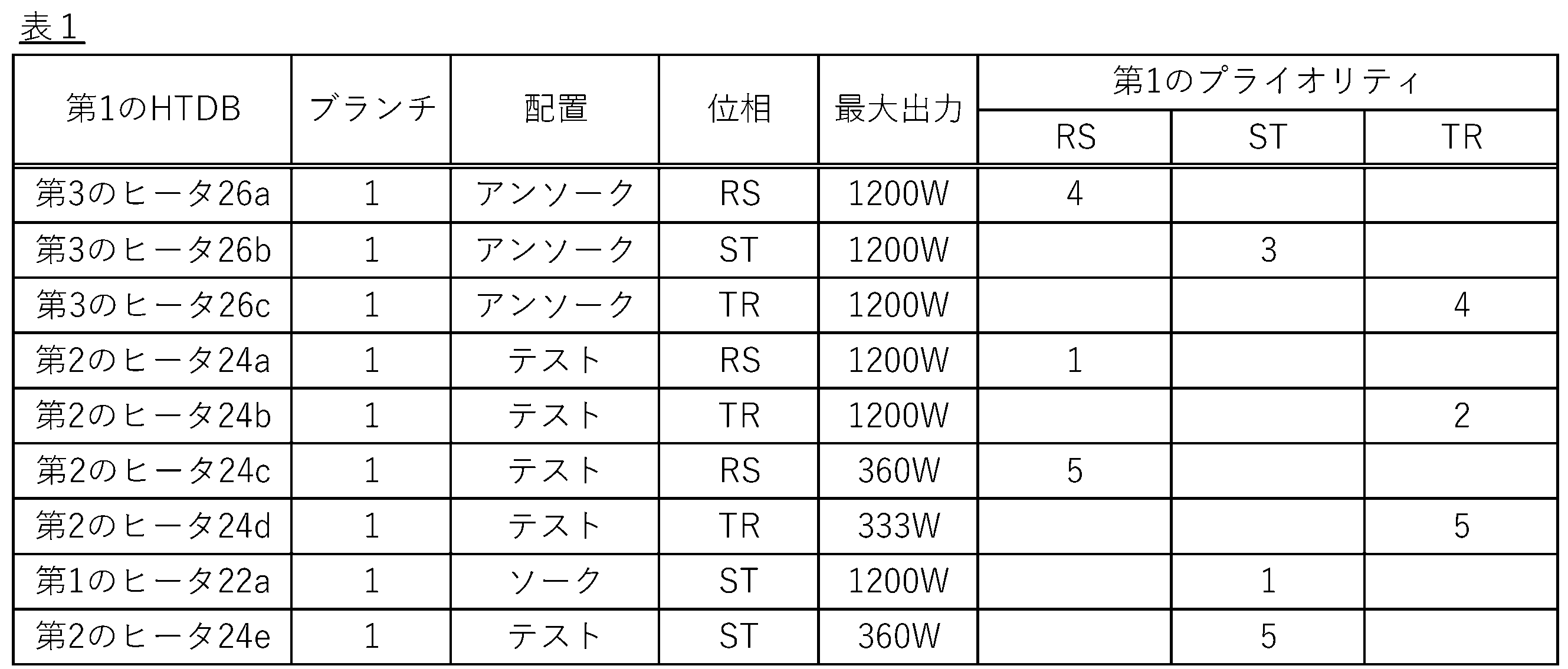
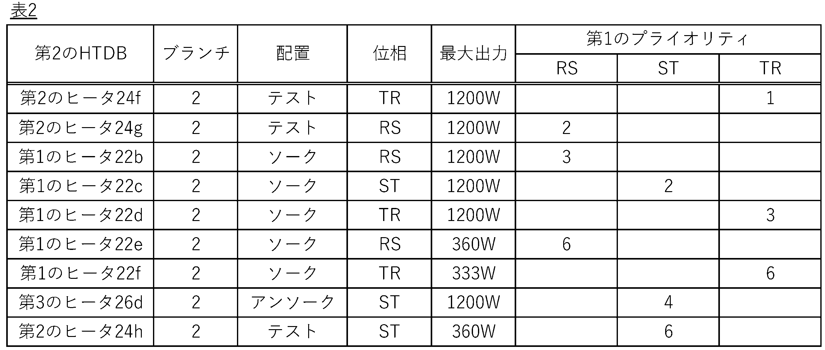
上記のような第2のプライオリティに基づいて設定された第1のプライオリティは、例えば、下記表1及び表2に示すような第1のプライオリティに設定することができる。表1は、第1のHTDB36aを介して電力を供給されるヒータの第1のプライオリティを表しており、表2は、第2のHTDB36bを介して電力を供給されるヒータの第1のプライオリティを表している。
The first priority set based on the second priority as described above can be set to, for example, the first priorities shown in Tables 1 and 2 below. Table 1 represents the first priorities of heaters powered via the
[第1の駆動制御方法]
上記の表1及び表2に示すように第1のプライオリティに基づくヒータの第1の駆動制御方法について、図を参照しながら説明する。図6は、本実施形態におけるヒータ駆動制御装置30による第1の駆動制御を説明するためのグラフである。
[First drive control method]
A first drive control method for the heater based on the first priority as shown in Tables 1 and 2 above will be described with reference to the drawings. FIG. 6 is a graph for explaining the first drive control by the heater
なお、図6において、ISOAKは、ソークチャンバ21に配置されている第1のヒータ22a~22fに供給されている電流の総和である。ITESTは、テストチャンバ23に配置されている第2のヒータ24a~24fに供給されている電流の総和である。IUNSOAKは、アンソークチャンバ25に配置されている第3のヒータ26a~26dに供給されている電流の総和である。
Note that in FIG. 6, I SOAK is the sum of the currents supplied to the
また、TSOAKはソークチャンバ21の内部の温度変化を示す線グラフであり、TTESTはテストチャンバ23の内部の温度変化を示す線グラフであり、TUNSOAKは、アンソークチャンバ25の内部の温度変化を示す線グラフである。
Further, T SOAK is a line graph showing the temperature change inside the soak
表1及び表2に示すような第1のプライオリティでは、まず、表1及び表2においてプライオリティ1に設定された第2のヒータ24a,24fに相電流IRS,ITRを供給すると共に、第1のヒータ22aに相電流ISTを供給する(図6の第1の駆動)。つまり、3相の相電流のうち2相をテストチャンバ23の内部の昇温に使用し、1相をソークチャンバ21の内部の昇温に使用する(第1の昇温駆動)。
In the first priority as shown in Tables 1 and 2, first, the phase currents I RS and I TR are supplied to the
このとき、第2のヒータ24a,24f及び第1のヒータ22aを最大出力(本例では、1200W)で駆動させてもよい。ここでは、図6に示すように、第1の駆動において第2のヒータ24a,24f及び第1のヒータ22aを最大出力で駆動させた場合のITESTとISOAKの和がILIMITとなっている(ISOAK1+ITEST1=ILIMIT)。
At this time, the
この第1の駆動では、図6に示すように、ITEST1がISOAK1よりも大きくなっており(ITEST1>ISOAK1)、ITEST1とISOAK1の比は2:1となっている(ITEST1:ISOAK1z=2:1)。このようにして、テストチャンバ23の内部が最優先で昇温され、ソークチャンバ21の内部が次に優先されて昇温されている。
In this first drive, as shown in FIG. 6, I TEST1 is larger than I SOAK1 (I TEST1 > I SOAK1 ), and the ratio of I TEST1 and I SOAK1 is 2:1 (I TEST1 :I SOAK1z =2:1). In this way, the temperature inside the
次に、第2のヒータ24a,24f及び第1のヒータ22aの近傍が所定の温度に到達した後に、第2のヒータ24a,24f及び第1のヒータ22aに供給する電流を減らす(第1の保温駆動)。第2のヒータ24a,24f及び第1のヒータ22aに供給する電流量は、所定の温度を維持できる程度の量であればよい。
Next, after the vicinity of the
このような第1の保温駆動と同時に、表1及び表2のプライオリティ2に設定された第2のヒータ24b,24gに相電流IRS,ITRを供給すると共に、第1のヒータ22cに相電流ISTを供給する(図6の第2の駆動)。この第2の駆動においても、第1の駆動と同様に、3相の相電流のうち2相をテストチャンバ23の内部の昇温に利用し、1相をソークチャンバ21の内部の昇温に利用している(第2の昇温駆動)。図6に示すように、このような第1及び第2の駆動により、テストチャンバ23の内部の温度が最初に目標温度TTARGET1に到達する。
Simultaneously with such first heat retention driving, phase currents I RS and I TR are supplied to the
テストチャンバ23の内部の温度が目標温度TTARGET1に到達した後に、第2のヒータ24a~24fに供給する電流を減らし(第2の保温駆動)、表1及び表2のプライオリティ3に設定された第1のヒータ22b,22dに相電流IRS,ITRを供給すると共に、第3のヒータ26bに相電流IRSを供給する(図6の第3の駆動)。つまり、第3の駆動では、第1及び第2の保温駆動と同時に、第1のヒータ22b,22d及び第3のヒータ26bによる第3の昇温駆動が実行される。
After the internal temperature of the
図6に示すように、この第3の駆動では、目標温度TTARGET1を維持するために第2のヒータ24a~24fが必要とする電流ITEST2を上限電流ILIMITから減じた余裕分(ILIMIT-ITEST2=ISOAK3+IUNSOAK1)を用いて、ソークチャンバ21の内部を2個の第1のヒータ22b、22dにより昇温し、アンソークチャンバ25の内部を1個の第3のヒータ26bにより昇温する。この第3の駆動では、図6に示すように、ISOAK3がIUNSOAK1よりも大きくなっており(ISOAK3>IUNSOAK1)、ISOAK3とIUNSOAK1の比は2:1となっている(ISOAK3:IUNSOAK1=2:1)。
As shown in FIG . 6, in this third drive, the margin ( I LIMIT -I TEST2 =I SOAK3 +I UNSOAK1 ), the inside of the soak
第3の駆動によってソークチャンバ21の内部の温度が目標温度TTARGET2に到達し、かつ、第3のヒータ26bの近傍が所定の温度に到達した後は、第1のヒータ22b、22d及び第3のヒータ26bに供給する電流を減らし(第3の保温駆動)、表1及び表2のプライオリティ4に設定された第3のヒータ26a,26c,26dに相電流IRS,IST,ITRを供給する(図6の第4の駆動)。つまり、第4の駆動では、第1~第3の保温駆動と同時に、第3のヒータ26a,26c,26dによる第4の昇温駆動が実行される。
After the temperature inside the soak
図6に示すように、この第4の駆動では、目標温度TTARGET1,TTARGET2を維持するために第1及び2のヒータ22b、22d,24a~24fが必要とする電流(ITEST4+ISOAK4)を上限電流ILIMITから減じた余裕分(ILIMIT-(ITEST4+ISOAK4)=IUNSOAK2)を用いて、3個の第3のヒータ26a,26c,26dを駆動させて、3個の第3のヒータ26a,26c,26dの近傍を所定の温度まで昇温させる。第3のヒータ26a~26dの近傍を所定の温度まで昇温させることで、結果的に、アンソークチャンバ25の内部の温度が目標温度TTARGET1に到達する。
As shown in FIG. 6, in this fourth drive, the current (I TEST4 +I SOAK4 ) required by the first and
第4の駆動によってアンソークチャンバ25の内部の温度が目標温度TTARGET3に到達した後、第3のヒータ26a,26c,26dに供給する電流を減らし(第4の保温駆動)、表1及び表2のプライオリティ5に設定された出力の小さい第2のヒータ24c~24eに相電流IRS,IST,ITRを供給する(図6の第5の駆動)。つまり、第5の駆動では、第1~第4の保温駆動と同時に、出力の小さい第2のヒータ24c~24eによる第5の昇温駆動が実行される。
After the temperature inside the
本実施形態では、第2のヒータ24c~24e,24h及び第1のヒータ22e,22fの出力が比較的小さくなっているので、例外的に、これらのヒータの第1のプライオリティは出力の大きいヒータに比べて低く設定される。つまり、出力の小さいヒータは、出力の大きいヒータよりも後にオンされる。
In this embodiment, since the outputs of the
但し、この出力の小さいヒータの中でも、テストチャンバ23に設けられている第2のヒータ24c~24eの第1のプライオリティは、ソークチャンバ21に設けられている第1のヒータ22e,22fの第1のプライオリティよりも高く設定されている。
However, among these heaters with low output, the first priority of the
第2のヒータ24c~24eの近傍が所定の温度に到達した後に、第2のヒータ24c~24eに供給する電流を減らし(第5の保温駆動)、表1及び表2のプライオリティ6に設定された第1のヒータ22e,22fに相電流IRS,ITRを供給すると共に、残りの第2のヒータ24hに相電流ISTを供給する(図6の第6の駆動)。つまり、第6の駆動では、第1~第5の保温駆動と同時に、出力の小さい第1のヒータ22e,22f及び第2のヒータ24hによる第6の昇温駆動が実行される。
After the vicinity of the
最終的に、第1のヒータ22e,22fの近傍と、第2のヒータ24hの近傍と、が所定の温度まで昇温された後、全ての第1~第3のヒータ22a~22f,24a~24h,26a~26dを保温駆動させることにより、各々のチャンバ21,23,25の内部の温度を維持する(図6の第7の駆動)。以上の様にして、第1の駆動制御方法が実行される。
Finally, after the vicinity of the
なお、表1及び表2に示す第1のプライオリティは、ヒータが配置されるチャンバの種類に応じて設定されているがこれに限定されない。例えば、第1のプライオリティは、ヒータの出力に応じて設定されてもよいし、チャンバの内部における場所の重要度等の他の指標に基づいて設定されてもよい。 Note that the first priority shown in Tables 1 and 2 is set according to the type of chamber in which the heater is arranged, but is not limited thereto. For example, the first priority may be set according to the output of the heater, or may be set based on other indicators such as the importance of a location inside the chamber.
また、第1のプライオリティは、以下のように変更されてもよい。すなわち、上記の温度センサにより検出されたテストチャンバ23の内部の検出温度と目標温度TTARGET1との第1の温度差と、ソークチャンバ21の内部の検出温度と目標温度TTARGET2との第2の温度差と、アンソークチャンバ25の内部の検出温度と目標温度とTTARGET2との第3の温度差を算出し、第1~第3の温度差に基づいて、第1のプライオリティを変更してもよい。
Further, the first priority may be changed as follows. That is, a first temperature difference between the detected temperature inside the
この場合、図2に示すように、温度センサ群38に含まれる各温度センサによって検出された検出値を計測ボード37及び通信ボード34を介してPC33のプライオリティ作成部33aに入力する。そして、このプライオリティ作成部33aにおいて、第1~第3の温度差を算出し、第1~第3の温度差に基づいて、第1のプライオリティを変更する。より具体的には、第1~第3の温度差に基づき、最も目標温度との温度差の大きいチャンバを特定し、当該チャンバ内に配置されているヒータの第1のプライオリティを上げることによって、目標温度との乖離が大きいチャンバを優先的に昇温させることができる。
In this case, as shown in FIG. 2, the detection values detected by each temperature sensor included in the
また、本実施形態では、コンタクトユニット20を1個のみ備える電子部品試験装置1を例示したが、複数のコンタクトユニット20を備える電子部品試験装置においては、コンタクトユニット20毎に設定された第3のプライオリティに基づいて、第1のプライオリティを変更してもよい。
Further, in this embodiment, the electronic
図7は、本実施形態におけるコンタクトユニット20を複数備えている電子部品試験装置1において、第3のプライオリティに基づく第1のプライオリティの変更の一例を示す説明図である。なお、2個のコンタクトユニット20を備えている電子部品試験装置1を例示するが、電子部品試験装置1は、コンタクトユニット20を3個以上有していてもよい。
FIG. 7 is an explanatory diagram showing an example of changing the first priority based on the third priority in the electronic
図7に示す第1及び第2のコンタクトユニット20A,20Bは、いずれも、図1に示したコンタクトユニット20と同様の構造を有している。この場合、ヒータ駆動制御装置30は、図7に示すように、第1のコンタクトユニット20Aのヒータの駆動を制御する第1及び第2のHTDB36a,36bに加えて、第2のコンタクトユニット20Bのヒータの駆動を制御する第3及び第4のHTDB36c,36dをさらに有している。そして、分岐ブレーカ31bは、これらの第3及び第4のHTDB36c,36dにそれぞれ接続するブランチ3,4をさらに有している。
The first and
第1及び第2のコンタクトユニット20A,20Bのヒータに対しては、基本的に、それぞれ、上記表1及び表2と同様の第1のプライオリティが設定されるが、図7に示すように、第1のコンタクトユニット20A,20B毎に設定された第3のプライオリティに基づいて第1のプライオリティを変更してもよい。
Basically, the same first priorities as in Tables 1 and 2 above are set for the heaters of the first and
例えば、図7に示すように、第1のコンタクトユニット20Aの第3のプライオリティが、第2のコンタクトユニット20Bの第3のプライオリティよりも高い場合には、第1のコンタクトユニット20Aのソークチャンバ21、テストチャンバ23、及び、アンソークチャンバ24における昇温が完了した後に、第2のコンタクトユニット20Bのソークチャンバ21,テストチャンバ23,及びアンソークチャンバ24における昇温を開始する。
For example, as shown in FIG. 7, if the third priority of the
このように、各コンタクトユニット20A,20Bのヒータに対して設定される第1のプリオリティは共通のものとすることができるため、電子部品試験装置1が複数のコンタクトユニット20A,20Bを備えている場合であっても、回路設計が容易となる。
In this way, the first priority set for the heaters of each
また、例えば、一方の第2のコンタクトユニット20Bが故障から復帰する場合には、第2のコンタクトユニット20Bの第3のプライオリティを高くする。これにより、第2のコンタクトユニット20Bの各チャンバ内の温度の復帰速度を速めることができる。
Further, for example, when one of the
以上のように、本実施形態におけるヒータ駆動制御装置によるヒータ駆動制御方法では、制御装置30が第1~第3のヒータ22a~22f,24a~24h,26a~26dに対して設定された第1のプライオリティに応じて、第1~第3のヒータ22a~22f,24a~24h,26a~26dに供給する電流の和がブレーカの定格電流の範囲内となるように、第1~第3のヒータ22a~22f,24a~24h,26a~26dに順に電流を供給する第1の駆動制御を実行する。このため、図6に示すように、ピーク電流が大きくなりすぎないため、電源系統のサイズを最適化できる。
As described above, in the heater drive control method using the heater drive control device according to the present embodiment, the
図8は、比較例におけるヒータ駆動制御を説明するためのグラフである。従来のヒータ駆動制御装置では、図8の比較例に示すように、コンタクトユニットのソークチャンバ、テストチャンバ、及び、アンソークチャンバにおける全てのヒータを同時にオンするため、最初にピーク電流が大きくなる。このため、このピーク電流に対応するための電源やブレーカが必要となり、電源系統が大型化してしまう。 FIG. 8 is a graph for explaining heater drive control in a comparative example. In the conventional heater drive control device, as shown in the comparative example of FIG. 8, all the heaters in the soak chamber, test chamber, and unsoak chamber of the contact unit are turned on at the same time, so the peak current increases at first. Therefore, a power supply and a breaker are required to handle this peak current, resulting in an increase in the size of the power supply system.
また、図6に示すように、本実施形態におけるヒータ駆動制御装置によるヒータ駆動制御方法では、供給する電流の量を平滑化することができるため、電源系統の有効活用を図ることができる。 Further, as shown in FIG. 6, in the heater drive control method using the heater drive control device according to the present embodiment, the amount of supplied current can be smoothed, so that the power supply system can be used effectively.
これに対して、図8に示すように、比較例では、各々のチャンバの温度を目標温度まで昇温した後は必要な電流が小さいため、大型の電源系統を十分に有効活用できていない。 On the other hand, as shown in FIG. 8, in the comparative example, the required current is small after the temperature of each chamber is raised to the target temperature, so that the large power supply system cannot be used effectively.
また、コンタクトユニット20は、高温運転、低温運転、常温運転、常温復帰運転(デフロスト)等の運転パターンを有している。運転パターンに応じて使用されないヒータが存在するが、使用されないヒータの本実施形態の第1のプライオリティを変更する必要は無い。
Further, the
なお、以上説明した実施形態は、本発明の態様の理解を容易にするために記載されたものであって、本発明の態様を限定するために記載されたものではない。したがって、上記の実施形態に開示された各要素は、本発明の技術的範囲に属する全ての設計変更や均等物をも含む趣旨である。 Note that the embodiments described above are described to facilitate understanding of the aspects of the present invention, and are not described to limit the aspects of the present invention. Therefore, each element disclosed in the above embodiments is intended to include all design changes and equivalents that fall within the technical scope of the present invention.
1…電子部品試験装置
5…テストヘッド
10…ハンドラ
20…コンタクトユニット
21…ソークチャンバ
22a~22f…第1のヒータ
23…テストチャンバ
24a~24h…第2のヒータ
25…アンソークチャンバ
26a~26d…第3のヒータ
30…ヒータ駆動制御装置
31…ブレーカ
31a…メインブレーカ(BCU)
31b…分岐ブレーカ(ACU)
311a…第1の配線群
311b…第2の配線群
32…制御装置
33…PC
33a…プライオリティ作成部
33b…記憶部
33c…オンオフ制御部
34…通信ボード
35…入出力ボード
36a、36b…第1及び第2のヒータドライバボード
361a…ヒューズ
361b…トライアック
37…計測ボード
38…温度センサ群
40…電源
DESCRIPTION OF
31b...Branch breaker (ACU)
311a...first wiring group
311b...
33a...Priority creation section
33b...Storage unit
33c...On/off
361a...fuse
361b...
Claims (10)
前記ヒータ駆動制御装置は、
電源から各々の前記ヒータに供給される電流を制御する制御装置と、
前記電源と前記複数のヒータとの間に配置されたブレーカと、を備え、
前記制御装置は、前記複数のヒータに供給する電流の和が前記ブレーカの定格電流の範囲内となるように、前記複数のヒータに対して設定された第1のプライオリティに応じて、前記複数のヒータに順に電流を供給する第1の駆動制御を実行するヒータ駆動制御装置。 A heater drive control device used in an electronic component testing device equipped with a test chamber, a soak chamber, and an unsoak chamber in which a plurality of heaters are provided,
The heater drive control device includes:
a control device that controls current supplied from a power source to each of the heaters;
a breaker disposed between the power source and the plurality of heaters,
The control device controls the plurality of heaters according to a first priority set for the plurality of heaters so that the sum of the currents supplied to the plurality of heaters is within the rated current range of the breaker. A heater drive control device that performs first drive control to sequentially supply current to the heaters.
前記制御装置は、所定のサイクルで前記複数のヒータを制御しており、
前記サイクル毎に、前記定格電流と、オン状態とする前記複数のヒータの電力から算出された線電流の和と、を比較し、
前記線電流の和が前記定格電流よりも大きい場合に、前記第1の駆動制御を実行するヒータ駆動制御装置。 The heater drive control device according to claim 1,
The control device controls the plurality of heaters in a predetermined cycle,
For each cycle, compare the rated current and the sum of line currents calculated from the power of the plurality of heaters to be turned on,
A heater drive control device that executes the first drive control when the sum of the line currents is larger than the rated current.
前記電源は三相交流電源であり、
前記線電流は、三相の線電流IR,IS,ITから構成されており、
前記制御装置は、前記第1の駆動制御において、前記線電流IR,IS,ITがバランスするように前記複数のヒータに順に電流を供給するヒータ駆動制御装置。 The heater drive control device according to claim 2,
The power source is a three-phase AC power source,
The line current is composed of three-phase line currents IR , IS , IT ,
The control device is a heater drive control device that sequentially supplies current to the plurality of heaters in the first drive control so that the line currents I R , IS , and I T are balanced.
前記第1のプライオリティは、前記テストチャンバ、前記ソークチャンバ、及び、前記アンソークチャンバ毎に設定された第2のプライオリティに基づいて設定されているヒータ駆動制御装置。 The heater drive control device according to claim 1,
In the heater drive control device, the first priority is set based on a second priority set for each of the test chamber, the soak chamber, and the unsoak chamber.
前記制御装置は、前記第1のプライオリティを変更可能な変更部を備え、
前記電子部品試験装置は、前記テストチャンバ、前記ソークチャンバ、及び、前記アンソークチャンバを備えたコンタクトユニットを複数備え、
前記変更部は、前記第1のプライオリティを、前記コンタクトユニット毎に設定された第3のプライオリティに基づいて変更するヒータ駆動制御装置。 The heater drive control device according to claim 1,
The control device includes a changing unit capable of changing the first priority,
The electronic component testing apparatus includes a plurality of contact units each including the test chamber, the soak chamber, and the unsoak chamber,
The changing unit is a heater drive control device that changes the first priority based on a third priority set for each contact unit.
前記制御装置は、
前記第1のプライオリティを変更可能な変更部と、
前記テストチャンバ、前記ソークチャンバ、及び、前記アンソークチャンバの内部に設けられた複数の温度センサと、を備え、
前記制御装置は、前記温度センサが検出した前記テストチャンバ、前記ソークチャンバ、及び、前記アンソークチャンバの内部の検出温度と、目標温度と、の温度差を算出し、
前記変更部は、前記第1のプライオリティを前記温度差に応じて変更するヒータ駆動制御装置。 The heater drive control device according to claim 1,
The control device includes:
a changing unit capable of changing the first priority;
The test chamber, the soak chamber, and a plurality of temperature sensors provided inside the unsoak chamber,
The control device calculates a temperature difference between the internal temperatures of the test chamber, the soak chamber, and the unsoak chamber detected by the temperature sensor and a target temperature,
The changing unit is a heater drive control device that changes the first priority according to the temperature difference.
前記複数のヒータは、
第1のヒータと、
前記第1のヒータよりも前記第1のプライオリティが低く設定されている第2のヒータと、を含んでおり、
前記制御装置は、前記第1の駆動制御において、前記第1のヒータに電流を供給し、前記第1のヒータへ供給する電流を減じてから、前記第2のヒータへ電流を供給するヒータ駆動制御装置。 The heater drive control device according to claim 1,
The plurality of heaters are
a first heater;
a second heater in which the first priority is set lower than that of the first heater,
In the first drive control, the control device supplies current to the first heater, reduces the current supplied to the first heater, and then supplies current to the second heater. Control device.
前記複数のヒータに供給する電流の和がブレーカの定格電流の範囲内となるように、前記複数のヒータに対して設定された第1のプライオリティに応じて、前記複数のヒータに順に電流を供給する第1の駆動制御工程を備えるヒータ駆動制御方法。 A heater drive control method for controlling the drive of a plurality of heaters provided inside a test chamber, a soak chamber, and an unsoak chamber of an electronic component testing device, the method comprising:
Supplying current to the plurality of heaters in order according to a first priority set for the plurality of heaters so that the sum of the currents supplied to the plurality of heaters is within a rated current range of the breaker. A heater drive control method comprising a first drive control step.
Priority Applications (5)
| Application Number | Priority Date | Filing Date | Title |
|---|---|---|---|
| JP2022090485A JP2023177687A (en) | 2022-06-02 | 2022-06-02 | Heater drive control device, electronic component handling device, electronic component testing device, and heater drive control method |
| TW112118906A TWI860717B (en) | 2022-06-02 | 2023-05-22 | Heater drive control device, electronic component transport device, electronic component testing device and heater drive control method |
| KR1020230068203A KR102849232B1 (en) | 2022-06-02 | 2023-05-26 | Heater drive control device, electronic component handling device, electronic component testing device and heater drive control method |
| US18/325,358 US20230393189A1 (en) | 2022-06-02 | 2023-05-30 | Heater drive controlling apparatus, electronic component handling apparatus, electronic component testing apparatus, and heater drive controlling method |
| CN202310617901.4A CN117177389A (en) | 2022-06-02 | 2023-05-30 | Heater drive control device, electronic component processing device, electronic component testing device, and heater drive control method |
Applications Claiming Priority (1)
| Application Number | Priority Date | Filing Date | Title |
|---|---|---|---|
| JP2022090485A JP2023177687A (en) | 2022-06-02 | 2022-06-02 | Heater drive control device, electronic component handling device, electronic component testing device, and heater drive control method |
Publications (1)
| Publication Number | Publication Date |
|---|---|
| JP2023177687A true JP2023177687A (en) | 2023-12-14 |
Family
ID=88934298
Family Applications (1)
| Application Number | Title | Priority Date | Filing Date |
|---|---|---|---|
| JP2022090485A Pending JP2023177687A (en) | 2022-06-02 | 2022-06-02 | Heater drive control device, electronic component handling device, electronic component testing device, and heater drive control method |
Country Status (5)
| Country | Link |
|---|---|
| US (1) | US20230393189A1 (en) |
| JP (1) | JP2023177687A (en) |
| KR (1) | KR102849232B1 (en) |
| CN (1) | CN117177389A (en) |
| TW (1) | TWI860717B (en) |
Family Cites Families (20)
| Publication number | Priority date | Publication date | Assignee | Title |
|---|---|---|---|---|
| JPH10136554A (en) * | 1996-10-31 | 1998-05-22 | Fuji Electric Co Ltd | Circuit breaker |
| JP4299383B2 (en) * | 1998-06-25 | 2009-07-22 | 株式会社アドバンテスト | IC test equipment |
| KR100380963B1 (en) * | 2000-11-10 | 2003-04-26 | 미래산업 주식회사 | Handler for Testing Module RAM |
| JP4173306B2 (en) * | 2001-11-30 | 2008-10-29 | 東京エレクトロン株式会社 | Reliability evaluation test apparatus, reliability evaluation test system, and reliability evaluation test method |
| US6897670B2 (en) * | 2001-12-21 | 2005-05-24 | Texas Instruments Incorporated | Parallel integrated circuit test apparatus and test method |
| JP4426155B2 (en) * | 2002-06-06 | 2010-03-03 | 株式会社タムラ製作所 | Heating device |
| KR100522793B1 (en) * | 2003-01-13 | 2005-10-18 | 한화기계주식회사 | System and method to optimize energy consumption of industrial furnaces |
| CN103476163B (en) * | 2005-12-26 | 2016-06-22 | 松下电器产业株式会社 | High-frequency heating apparatus and condition checkout gear thereof and method |
| CN101495819B (en) * | 2007-07-30 | 2011-08-17 | 株式会社爱德万测试 | Heat control device for electronic equipment |
| US8274300B2 (en) * | 2008-01-18 | 2012-09-25 | Kes Systems & Service (1993) Pte Ltd. | Thermal control unit for semiconductor testing |
| JP5879039B2 (en) | 2011-01-26 | 2016-03-08 | 美浜株式会社 | Temperature control system |
| US9677822B2 (en) * | 2012-02-27 | 2017-06-13 | M.D. Mechanical Devices Ltd. | Efficient temperature forcing of semiconductor devices under test |
| US9470720B2 (en) * | 2013-03-08 | 2016-10-18 | Sandisk Technologies Llc | Test system with localized heating and method of manufacture thereof |
| WO2015099726A1 (en) * | 2013-12-26 | 2015-07-02 | Schneider Electric It Corporation | Systems and methods for determining input current of a power distribution unit |
| KR102058443B1 (en) * | 2014-03-03 | 2020-02-07 | (주)테크윙 | Test handler and circulation method of test trays in test handler |
| TWI782508B (en) * | 2016-01-08 | 2022-11-01 | 美商艾爾測試系統 | Method and system for thermal control of devices in an electronics tester |
| JP6496346B2 (en) * | 2017-04-18 | 2019-04-03 | 株式会社東京精密 | Temperature control device |
| US11229094B2 (en) * | 2018-12-20 | 2022-01-18 | Nxp Usa, Inc. | Combined RF and thermal heating system and methods of operation thereof |
| DE102019213604A1 (en) * | 2019-09-06 | 2021-03-11 | Siemens Aktiengesellschaft | Circuit breaker, circuit breaker system and process |
| US11740279B2 (en) * | 2020-04-24 | 2023-08-29 | Kla Corporation | Measuring temperature-modulated properties of a test sample |
-
2022
- 2022-06-02 JP JP2022090485A patent/JP2023177687A/en active Pending
-
2023
- 2023-05-22 TW TW112118906A patent/TWI860717B/en active
- 2023-05-26 KR KR1020230068203A patent/KR102849232B1/en active Active
- 2023-05-30 CN CN202310617901.4A patent/CN117177389A/en active Pending
- 2023-05-30 US US18/325,358 patent/US20230393189A1/en active Pending
Also Published As
| Publication number | Publication date |
|---|---|
| CN117177389A (en) | 2023-12-05 |
| KR20230167715A (en) | 2023-12-11 |
| TW202411674A (en) | 2024-03-16 |
| TWI860717B (en) | 2024-11-01 |
| KR102849232B1 (en) | 2025-08-21 |
| US20230393189A1 (en) | 2023-12-07 |
Similar Documents
| Publication | Publication Date | Title |
|---|---|---|
| US11973202B2 (en) | Intelligent module interface for battery maintenance device | |
| JP7457208B2 (en) | A controller for controlling an automatic test equipment (ATE), an ATE, a method for controlling the ATE, a method for operating the ATE, and a computer for performing such a method, including estimating or determining temperature. program | |
| US20200006965A1 (en) | Device and process for discharging an intermediate circuit capacitor and process for producing a device for discharging an intermediate circuit capacitor | |
| US20240222731A1 (en) | Intelligent module interface for battery maintenance device | |
| JP7594528B2 (en) | Battery Control Unit | |
| CN109428318A (en) | Load control device and load control method | |
| US6833636B1 (en) | Compact load bank for testing power systems | |
| JP7147646B2 (en) | Battery module heating device | |
| JP2007502413A (en) | Self-heating burn-in | |
| JP2023177687A (en) | Heater drive control device, electronic component handling device, electronic component testing device, and heater drive control method | |
| CN100449438C (en) | Method for regulating a current through an electromagnetic control element | |
| TWI406346B (en) | Burn-in testing apperatures for semiconductor chip | |
| JP2000243795A (en) | Power supply current measurement circuit of burn-in tester | |
| CN219533328U (en) | Integrated circuit chip aging test device | |
| US20170331469A1 (en) | Method and device for operating power semiconductor switches connected in parallel | |
| CN108631568A (en) | Inverter system and its control method | |
| CN114415017A (en) | Dry-type load device gear configuration and switching method based on expert system | |
| JP3995079B2 (en) | Test equipment | |
| KR102867221B1 (en) | Probe card and operating method thereof | |
| US20250358902A1 (en) | Systems and methods for controlling a heater based on a differential current | |
| CN222125362U (en) | Control guide pressure testing device and testing system | |
| KR102768615B1 (en) | Burn-in test device for MLCC element | |
| JP4040741B2 (en) | Integrated circuit terminal floating inspection method and circuit board inspection apparatus | |
| US20120306519A1 (en) | Method for the phase diagnosis of a multiphase converter | |
| JP7515900B2 (en) | Electronic Component Test Equipment |