JP2023168963A - Charging/discharging device, charging/discharging control method, and computer program - Google Patents
Charging/discharging device, charging/discharging control method, and computer program Download PDFInfo
- Publication number
- JP2023168963A JP2023168963A JP2022080375A JP2022080375A JP2023168963A JP 2023168963 A JP2023168963 A JP 2023168963A JP 2022080375 A JP2022080375 A JP 2022080375A JP 2022080375 A JP2022080375 A JP 2022080375A JP 2023168963 A JP2023168963 A JP 2023168963A
- Authority
- JP
- Japan
- Prior art keywords
- charging
- discharging device
- discharging
- signals
- external signal
- Prior art date
- Legal status (The legal status is an assumption and is not a legal conclusion. Google has not performed a legal analysis and makes no representation as to the accuracy of the status listed.)
- Granted
Links
- 238000007599 discharging Methods 0.000 title claims abstract description 186
- 238000000034 method Methods 0.000 title claims abstract description 27
- 238000004590 computer program Methods 0.000 title claims abstract description 11
- 238000004891 communication Methods 0.000 description 36
- 238000010586 diagram Methods 0.000 description 25
- 238000012423 maintenance Methods 0.000 description 18
- 238000010248 power generation Methods 0.000 description 5
- 230000002159 abnormal effect Effects 0.000 description 4
- 230000004044 response Effects 0.000 description 4
- 238000012546 transfer Methods 0.000 description 4
- 230000005856 abnormality Effects 0.000 description 3
- 238000012545 processing Methods 0.000 description 3
- 230000001681 protective effect Effects 0.000 description 3
- 238000011084 recovery Methods 0.000 description 3
- 230000007704 transition Effects 0.000 description 3
- 230000005611 electricity Effects 0.000 description 2
- 238000005516 engineering process Methods 0.000 description 2
- 239000000446 fuel Substances 0.000 description 2
- 230000006399 behavior Effects 0.000 description 1
- 230000002457 bidirectional effect Effects 0.000 description 1
- 230000007423 decrease Effects 0.000 description 1
- 230000002542 deteriorative effect Effects 0.000 description 1
- 238000012840 feeding operation Methods 0.000 description 1
- 238000009434 installation Methods 0.000 description 1
Images


Landscapes
- Supply And Distribution Of Alternating Current (AREA)
- Charge And Discharge Circuits For Batteries Or The Like (AREA)
Abstract
Description
本発明は、車両に設けられた蓄電池に対する充放電を制御する充放電装置、充放電制御方法、及びコンピュータプログラムに関する。 The present invention relates to a charging/discharging device, a charging/discharging control method, and a computer program for controlling charging/discharging of a storage battery installed in a vehicle.
電気自動車に備えられている蓄電池の電池容量は比較的大容量である。これらの車両の蓄えられた電力を、電気自動車の駆動以外に、例えば家庭内の負荷へ供給することを可能とするV2H(Vehicle to Home )を実現する技術が提案されている。V2Hに限らず、より規模の大きい建物への電力供給を可能とするV2B(Vehicle to Building )、電力網への供給を可能とするV2G(Vehicle to Grid )を含むV2Xを実現する技術が提案されている。これらの技術により、災害発生によって停電状態となったとしても、移動が可能な電気自動車に蓄えられた電力を供給して生活を維持したり、工場の稼働を維持したりすることが期待できる。 The storage battery installed in an electric vehicle has a relatively large capacity. Techniques have been proposed to realize V2H (Vehicle to Home), which enables the power stored in these vehicles to be supplied to, for example, household loads in addition to driving electric vehicles. Technologies to realize V2X have been proposed, including not only V2H but also V2B (vehicle to building), which enables power supply to larger buildings, and V2G (vehicle to grid), which enables power supply to the power grid. There is. With these technologies, it is expected that even in the event of a power outage due to a disaster, it will be possible to supply electric power stored in mobile electric vehicles to maintain daily life and keep factories operating.
V2Xの実現には、車両の蓄電池に接続される充放電用ケーブルを有し、車両における充放電の制御と、電力網からの電力供給とを調整して充放電制御を実施することができる充放電装置の配備が必要になる。特許文献1には、停電時であっても自立運転を行なうことが可能な充放電装置が開示されている。
Achieving V2X requires a charging/discharging cable that is connected to the storage battery of the vehicle, and is capable of controlling charging/discharging in the vehicle and adjusting the power supply from the power grid. Equipment will need to be deployed.
充放電装置は、電力供給源である電力網が停電した場合や逆電力を検出した場合に一旦、安全に運転を停止したり、地絡していることが検出された場合に安全に運転を停止したりするなど、状況に応じた所定の制御を、外部停止信号に応じて実施するように設定されている。 A charging/discharging device can safely stop operation once the power grid that supplies the power is out of power or detects reverse power, or if a ground fault is detected. The system is set to carry out predetermined control depending on the situation in response to an external stop signal.
充放電装置による所定の制御は、使用環境や、その用途に応じて多様に設定できることが好ましい。 It is preferable that the predetermined control by the charging/discharging device can be set in a variety of ways depending on the usage environment and its purpose.
本発明は、斯かる事情を鑑みてなされたものであり、外部からの信号に対してどのように動作するかの制御を、多様に設定可能な充放電装置、充放電制御方法、及びコンピュータプログラムを提供することを目的とする。 The present invention has been made in view of the above circumstances, and provides a charging/discharging device, a charging/discharging control method, and a computer program that allow various settings for controlling how the device operates in response to external signals. The purpose is to provide
本開示の一実施形態の充放電装置は、車両に設けられた蓄電池と接続され、前記蓄電池と、電源又は負荷との間で充放電を制御する制御部を備える充放電装置であって、前記充放電装置は、前記車両に搭載される機器を除く機器から1又は複数の信号を受け付ける外部信号受付部を備え、前記制御部は、前記外部信号受付部で受け付ける1又は複数の信号のオンが検知された場合の前記充放電装置の待機、及び停止を含む動作内容の設定を、前記1又は複数の信号別に、充電中、放電中及び自立給電中を含む運転状況毎に受け付け、受け付けた動作内容の設定を、前記1又は複数の信号別に、運転状況毎に記憶しておき、前記外部信号受付部で受け付ける1又は複数の信号のオンが検知された場合、記憶してある設定に従って動作させる。 A charging and discharging device according to an embodiment of the present disclosure is a charging and discharging device that is connected to a storage battery provided in a vehicle and includes a control unit that controls charging and discharging between the storage battery and a power source or a load, the charging and discharging device comprising: The charging/discharging device includes an external signal reception unit that receives one or more signals from equipment other than equipment mounted on the vehicle, and the control unit controls whether the one or more signals received by the external signal reception unit are turned on. Settings for operation contents including standby and stop of the charging/discharging device when detected are accepted for each of the one or more signals and for each operating condition including charging, discharging, and self-sustaining power supply, and the accepted operation Content settings are stored for each of the one or more signals and for each driving situation, and when the one or more signals accepted by the external signal reception section are detected to be on, the device operates according to the stored settings. .
本開示の一実施形態の充放電制御方法は、車両に設けられた蓄電池と接続され、前記蓄電池と電源又は負荷との間で充放電を制御する充放電装置の制御方法であって、前記充放電装置は、前記充放電装置は、前記車両に搭載される機器を除く機器から1又は複数の信号を受け付ける外部信号受付部を備え、前記充放電装置の制御部は、前記外部信号受付部で受け付ける1又は複数の信号のオンが検知された場合の前記充放電装置の待機、及び停止を含む動作内容の設定を、前記1又は複数の信号別に、充電中、放電中及び自立給電中を含む運転状況毎に受け付け、受け付けた動作内容の設定を、前記1又は複数の信号別に、運転状況毎に記憶しておき、前記外部信号受付部で受け付ける1又は複数の信号のオンが検知された場合、記憶してある設定に従って動作させる。 A charging and discharging control method according to an embodiment of the present disclosure is a method for controlling a charging and discharging device that is connected to a storage battery provided in a vehicle and controls charging and discharging between the storage battery and a power source or a load, the method comprising: The charging and discharging device includes an external signal reception unit that receives one or more signals from equipment other than equipment mounted on the vehicle, and the control unit of the charging and discharging device includes an external signal reception unit that receives one or more signals from devices other than equipment mounted on the vehicle. Set the operation contents including standby and stop of the charging/discharging device when one or more signals to be accepted are detected to be on, including charging, discharging, and self-sustaining power supply for each of the one or more signals. The settings of the received operation contents are accepted for each driving situation and are stored for each driving situation for each of the one or more signals, and when the external signal reception unit detects that the one or more signals accepted are turned on. , operate according to the memorized settings.
本開示の一実施形態のコンピュータプログラムは、車両に設けられた蓄電池と接続され、前記蓄電池と電源又は負荷との間で充放電を制御する充放電装置に搭載されるコンピュータに、前記車両に搭載される機器を除く機器から1又は複数の信号を受け付ける外部信号受付部で受け付ける1又は複数の信号のオンが検知された場合の前記充放電装置の待機、及び停止を含む動作内容の設定を、前記1又は複数の信号別に、充電中、放電中及び自立給電中を含む運転状況毎に受け付け、受け付けた動作内容の設定を、前記1又は複数の信号別に、運転状況毎に記憶しておき、前記外部信号受付部で受け付ける1又は複数の信号のオンが検知された場合、記憶してある設定に従って動作するよう制御する処理を実行させる。 A computer program according to an embodiment of the present disclosure is installed in a computer installed in a charging/discharging device that is connected to a storage battery installed in a vehicle and controls charging and discharging between the storage battery and a power source or a load. Setting of operation contents including standby and stop of the charging/discharging device when one or more signals received by an external signal receiving unit that receives one or more signals from devices other than devices that are connected to the device is detected to be turned on, Accepting each of the one or more signals for each driving situation including charging, discharging, and self-sustaining power supply, and storing the settings of the accepted operation details for each of the one or more signals and each driving situation, When it is detected that one or more signals received by the external signal reception unit are turned on, a process is executed to control the operation according to the stored settings.
本開示の充放電装置、充放電制御方法、及びコンピュータプログラムでは、外部停止信号に応じた動作内容を、運転状況毎に設定可能である。充放電装置の制御部は、設定に従って動作するように制御する。充電中である場合のみに運転を停止し、放電中(給電中)である場合、又は外部の電力網と接続されていない自立給電中である場合は、待機する、といった設定が可能になる。 In the charging/discharging device, the charging/discharging control method, and the computer program of the present disclosure, it is possible to set the operation content according to the external stop signal for each driving situation. The control unit of the charging/discharging device controls the charging/discharging device to operate according to the settings. It is possible to set the device to stop operation only when it is being charged, and to standby when it is discharging (supplying power) or when it is supplying independent power without being connected to an external power grid.
ここで外部停止信号は、車載機器を除く、充放電装置が設置されている環境における状況を検知する機器からの信号をいう。また外部停止信号は、公衆通信網を介して得られる通信信号を除いてもよい。機器は、保護継電器、センサ等であって、充放電装置を一旦停止させたり、待機させたりするべき状況であることを検知する機器を意味する。 Here, the external stop signal refers to a signal from a device that detects the situation in the environment in which the charging/discharging device is installed, excluding in-vehicle devices. Further, the external stop signal may exclude a communication signal obtained via a public communication network. The device refers to a device such as a protective relay or a sensor that detects a situation in which the charging/discharging device should be temporarily stopped or placed on standby.
充放電装置が使用する電力の契約状況、使用頻度等は、充放電装置が設置される環境に応じて異なるため、状況に関わらず、信号に対して停止するか待機するか、の二択では、ニーズに合わないケースが生じる。これに対し、環境に応じて状況毎の多様な設定が可能となることにより、充放電装置の充放電を適切に管理し、結果として電力使用効率を向上させることも期待できる。 The contract status, usage frequency, etc. of the electricity used by the charging/discharging device differ depending on the environment in which the charging/discharging device is installed, so regardless of the situation, there is no choice between stopping at the signal or waiting. , there will be cases where it does not meet your needs. On the other hand, by enabling various settings for each situation depending on the environment, charging and discharging of the charging/discharging device can be appropriately managed, and as a result, it is expected that power usage efficiency will be improved.
本開示の一実施形態の充放電装置では、前記制御部は、前記制御内容の設定として、待機及び停止に加えて、何もしないとの選択を受け付ける。 In the charging/discharging device according to an embodiment of the present disclosure, the control unit accepts a selection of not doing anything in addition to standby and stop as the control content settings.
本開示の充放電装置では、運転停止又は待機(のちに復帰)のみならず、何もしない、という選択も可能である。充電及び放電(給電)のいずれも可能な充放電装置であるため、発電中か否か、という2つの状況のみが想定されるパワーコンディショナ等と異なり、多様な対応が可能である。例えば、外部からの停止信号が検知されたとしても何ら反応せず、そのまま実行中の動作を継続してもよい状況があり得る。何もしない、という選択が可能であることにより、外部信号別の運転状況毎の適切な動作を充放電装置に行なわせることが可能である。 In the charging/discharging device of the present disclosure, it is possible not only to stop operation or standby (return later), but also to do nothing. Since it is a charging/discharging device capable of both charging and discharging (power supply), it can be used in a variety of ways, unlike power conditioners and the like, which assume only two situations: whether power is being generated or not. For example, even if a stop signal from the outside is detected, there may be a situation where no reaction is made and the current operation may continue. Since it is possible to select not to do anything, it is possible to cause the charging/discharging device to perform an appropriate operation for each driving situation depending on the external signal.
本開示の一実施形態の充放電装置では、前記外部信号受付部は、継電器から出力される外部停止信号を複数受け付ける。 In the charging/discharging device according to an embodiment of the present disclosure, the external signal receiving section receives a plurality of external stop signals output from the relay.
本開示の充放電装置では、外部信号として、継電器から出力されるRPR信号、及びOVGR信号等の継電器からの信号を複数受け付け、信号別に異なる動作をするように設定されていてもよい。 The charging/discharging device of the present disclosure may be configured to receive a plurality of signals from the relay, such as an RPR signal outputted from the relay and an OVGR signal, as external signals, and perform different operations for each signal.
本開示の一実施形態の充放電装置では、前記外部信号受付部は、接点出力信号を受け付ける。 In the charging/discharging device according to an embodiment of the present disclosure, the external signal receiving section receives a contact output signal.
本開示の充放電装置では、異常が検知された場合に他の装置から出力される接点出力信号を受け付けてもよい。接点出力信号は他の継電器からの信号と組み合わせられてもよい。 The charging/discharging device of the present disclosure may receive a contact output signal output from another device when an abnormality is detected. Contact output signals may be combined with signals from other relays.
本開示の一実施形態の充放電装置では、前記外部信号受付部は、外部スイッチの出力を受け付ける。 In the charging/discharging device according to an embodiment of the present disclosure, the external signal receiving section receives an output from an external switch.
本開示の充放電装置では、管理者等によって別途設けられるスイッチからの出力が受け付けられてもよい。他の継電器からの信号や、接点出力信号に対する設定と組み合わせてもよい。これにより、充放電装置の使用環境、使用目的等に応じた制御を多様に設定可能である。 In the charging/discharging device of the present disclosure, output from a switch separately provided by an administrator or the like may be accepted. It may be combined with settings for signals from other relays or contact output signals. This allows various control settings to be made depending on the usage environment, purpose of use, etc. of the charging/discharging device.
本開示によれば、充放電装置における外部からの信号に対する動作を多様に設定可能となる。 According to the present disclosure, it is possible to variously set the operation of the charging/discharging device in response to signals from the outside.
本開示をその実施の形態を示す図面を参照して具体的に説明する。 The present disclosure will be specifically described with reference to drawings showing embodiments thereof.
(第1実施形態)
図1は、充放電装置1を含む充放電システム200の概要図である。充放電システム200は、充放電装置1と、充放電装置1を介して供給可能な電力を使用する負荷21を含む。負荷21は、家庭、事業所等の建物内に配置されている電気負荷である。充放電システム200は、電力線PLにより、電力源である電力系統Eに接続されている。電力源は電力系統Eに限らず、直流電力網であってもよい。電力源からの供給電力は、分電盤28で負荷21及び充放電装置1へ分岐される。充放電システム200は、多数の車両Vで使用可能な駐車場に設置された複数の充放電装置1を含む構成であってもよい。充放電システム200は、その他、燃料電池を含んでもよい。
(First embodiment)
FIG. 1 is a schematic diagram of a charging/
充放電装置1には、蓄電装置を内蔵する電気自動車である車両Vが接続される。充放電装置1は、車両Vの蓄電装置への充電が可能であるとともに、車両Vの蓄電措置を電力源として負荷21へ給電することも可能である。
A vehicle V, which is an electric vehicle having a built-in power storage device, is connected to the charging/discharging
充放電システム200は、図1に示すように、充放電装置1及び負荷21のみならず、連系装置である蓄電装置22又は発電装置23等を含んでもよいし、通信線CLを介して上位装置29と接続されていてもよい。上位装置29は、充放電装置1に接続されている場合、電力源からの負荷21への電力の授受、及び、発電装置23からの負荷21群への電力授受、充放電装置1への車両Vにおける充放電を制御する。上位装置29は、図1に示すように、サーバ装置として外部に設けられて遠隔から制御するものであってもよいし、分電盤28に設置された建物内での電力の需給、充放電、発電等を制御するHEMS(Home Energy Management System)であってもよい。上位装置29は、充放電装置1に内蔵されて充放電を制御するものであってもよい。
As shown in FIG. 1, the charging/discharging
充放電システム200には、地絡過電圧継電器24、又は逆電力継電器25等の保護継電器が含まれている。これらの保護継電器から出力される信号(RPR(Reverse Power Relay )信号、OVGR(Overvoltage Relay )信号等)が充放電装置1に入力されている。これにより、充放電装置1は、システム内で地絡が起こった場合や、逆電力が発生した場合等、運転を停止すべき状態になったことが検知された場合に、これを検知することができる。
The charging/discharging
図2は、充放電装置1及び車両Vの接続構成を示すブロック図である。車両Vは、電気自動車(EV:Electric Vehicle)、ハイブリッド電気自動車(HEV:Hybrid Electric Vehicle)、プラグインハイブリッド車(PHEV:Plug-in Hybrid Electric Vehicle)、又は燃料電池自動車(FCV:Fuel Cell Vehicle )である。
FIG. 2 is a block diagram showing the connection configuration of the charging/discharging
車両Vは、その駆動に用いることが可能な大容量の蓄電装置30を備える。車両Vは、蓄電装置30に接続される電力線VPLへのコネクタ35と、蓄電装置30における充放電を制御する車載制御装置32とを備える。電力線VPLには、車両V側の充放電回路に含まれるDCリレー33が介装されており、車載制御装置32がDCリレー33のON及びOFFを制御する。コネクタ35には車載制御装置32と通信接続するための通信端子が含まれている。
Vehicle V includes a large-capacity
充放電装置1は、充放電回路10、制御部11、車両通信部12、電源部13、操作部14、外部信号受付部17及び上位通信部16を備える。充放電回路10は、双方向インバータ、各種リレー等の多様な回路素子を含む。充放電回路10は、車両Vと接続するコネクタ15と接続されるDCリレー10aと、電力系統Eと接続される電力線PLに介装された解列リレー10bとを含む。充放電回路10は、DCリレー10aを介してコネクタ15と電力線PLによって接続されている。
The charging/discharging
制御部11は、充放電回路10に含まれる回路素子を制御し、車両Vの蓄電装置30に対する充放電の切り替え、電流量、及び電圧量を制御する。制御部11はCPU(Central Processing Unit)及び不揮発性のメモリを含み、CPUはメモリに記憶されたコンピュータプログラム1Pに基づく制御処理を実行して充放電回路10を制御する。
The control unit 11 controls circuit elements included in the charging/discharging
制御部11のメモリに記憶されているコンピュータプログラム1Pは、コンピュータから読み取り可能な記憶媒体9に記憶されていたコンピュータプログラム9PをCPUが読み出してメモリに記憶したものであってもよい。
The computer program 1P stored in the memory of the control unit 11 may be one in which the CPU reads out the
車両通信部12は、コネクタ15及びコネクタ35を介して車載制御装置32と通信接続が可能である。車両通信部12の通信接続のプロトコルは車両V、コネクタ15,35に対応する充放電方式に準拠していればよく、異なる充放電方式に適用するように複数のプロトコルに対応していずれかを選択的に実行できてもよい。本実施形態では車両通信部12は、CAN(Controller Area Network)によって車載制御装置32と通信する。PLC(Power Line Communication)によって通信が実現されてもよい。
The
電源部13は、UPS(Uninterruptible Power Systems)回路及び起動用蓄電池を含み、制御部11へ電力を供給する。電源部13は、停電時には起動用蓄電池から充放電装置1の起動に必要な電力を供給する。電源部13は、電力系統E、発電装置23又は車両Vからの電力を起動用蓄電池に充電してもよい。
The
操作部14は、ディスプレイ、ディスプレイ内蔵タッチパネル、及び物理ボタンを含む。操作部14は、充放電装置1の外装に露出してタッチパネル操作を受け付ける。操作部14は、充放電装置1の本体とは隔離された構成としてよく、例えば、建物内のリモートコントーラとして構成されてもよい。操作部14は、管理者(ユーザ)が所持するスマートフォン又はタブレット端末等の通信端末の操作インタフェースで受け付けた操作情報を、無線通信を介して受け付ける構成であってもよい。制御部11は、操作部14にて受け付けられた操作に基づいて後述する設定受付処理を実行する。操作部14は、ランプを含み、状態に応じた色又はパターンで点灯するように制御部11によって制御されてもよい。
The
上位通信部16は、上位装置29と通信線CLを介して又は無線通信を介して通信を実現する。上位通信部16は例えば、Ethernet(登録商標)あるいはModbus(登録商標)プロトコルに準拠した通信線CLに対応する通信モジュールであってもよいし、ECHONET /ECHONETLite (登録商標)対応の通信線CLに対応する通信モジュールであってもよい。上位通信部16は、PLCにより通信を実現してもよい。上位通信部16は、WiFi(登録商標)、 Bluetooth(登録商標)又はキャリア通信に対応する無線通信モジュールであってもよい。
The higher-
外部信号受付部17は、充放電装置1の外部から出力される信号を受け付ける端子である。外部信号受付部17は例えば、PRP信号、OVGR信号等、その他、充放電システム200内外の継電器から出力される信号を受け付ける。外部信号受付部17は、後述するように、充放電システム200内に設けられたスイッチからの出力を受け付けてもよい。外部信号受付部17は、1又は複数の信号を受け付ける。以下の説明では、外部信号受付部17は、2つの信号を受け付けるものとして説明する。制御部11は、外部信号受付部17で受け付けられた信号の信号レベルを検知し、メモリに記憶してある各端子で入力された信号に応じた動作設定に基づき、停止、待機等への遷移を制御する。動作内容の設定は、後述するように操作部14に対する操作によって変更可能である。
The external
上述のように構成される充放電装置1の充放電回路10は、図1及び図2に示すように、コネクタ15が車両Vのコネクタ35と接続された状態において、DCリレー10a及び車両V側のDCリレー33を介して車両Vの蓄電装置30と電力線PLにより接続されている。充放電回路10は、図1及び図2に示すように、解列リレー10b及び分電盤28を介して電力系統E、及び連系機器(蓄電装置22、発電装置23等)と電力線PLによって接続されている。充放電装置1は、電力系統Eと、車両Vの蓄電装置30、及び連系機器との間の電力の授受を制御する。充放電回路10は、解列リレー10b、DCリレー10a、及びDCリレー33が全てONの状態の場合に、電力線PLを介して蓄電装置30の蓄電装置22や負荷への放電、又は電力系統Eからの蓄電装置30への充電を実施できる。
As shown in FIGS. 1 and 2, the charging/discharging
充放電装置1の制御部11は、車両通信部12を介して車載制御装置32と情報を送受信し、その情報に基づいて充放電回路10を制御する。制御部11は、上位通信部16を介して送受信される上位装置29からの情報に基づいて制御を実行してもよい。充放電装置1の制御部11は特に、充放電を実行する前に、車載制御装置32との間で所定の接続シーケンスを実行し、充放電開始が可能な状態となる。所定の接続シーケンスは例えば、CHAdeMO (登録商標)等の充放電制御規格で規定されている。
The control unit 11 of the charging and discharging
充放電装置1は、外部信号受付部17に入力される外部信号に基づく制御部11の制御内容を設定可能である。図3は、第1実施形態における設定受付手順の一例を示すフローチャートである。充放電装置1の操作部14のディスプレイに表示されている操作画面に対し、管理者あるいは保守担当者が設定メニューのオプション設定を選択すると、以下の処理が開始される。
The charging/discharging
充放電装置1の制御部11は、外部信号受付部17の2つの端子のいずれかの選択を受け付ける(ステップS101)。ステップS101において制御部11は、外部信号受付部17が含む端子の数に応じて、何番目なのかの選択を受け付ける。
The control unit 11 of the charging/discharging
制御部11は、選択された端子に対し、後述の動作内容を実行する状況を、「充電中」、「給電中」及び「自立給電中」のいずれかを選択する(ステップS102)。制御部11は、状況の識別データ(状況番号)をそのまま受け付けてもよい。 The control unit 11 selects one of "charging", "power supply", and "self-sustaining power supply" as the status for executing the operation details described below for the selected terminal (step S102). The control unit 11 may accept the situation identification data (situation number) as is.
制御部11は、選択された端子に入力される信号の信号レベルがオンとなった場合の動作内容の選択を、ステップS102で選択した状況別に受け付ける(ステップS103)。選択対象の動作内容は、第1実施形態では、第1に「待機(解除から300秒後に復帰)」、第2に「待機(解除から即時復帰)」、第3に「正常停止」、第4に「異常停止」、第5に「何もしない」である。制御部11は、動作内容の識別データ(動作内容番号)をそのまま受け付けてもよい。動作内容は、これに限られず、復帰までの時間は300秒に限らないし、6つ以上の選択対象があってもよい。 The control unit 11 receives the selection of the operation contents when the signal level of the signal input to the selected terminal is turned on, for each situation selected in step S102 (step S103). In the first embodiment, the operation contents to be selected are: 1st, "standby (returns after 300 seconds from release)", 2nd, "standby (immediate return from release)", 3rd, "normal stop", The fourth option is "abnormal stop" and the fifth option is "do nothing." The control unit 11 may accept the identification data (action content number) of the action content as is. The content of the operation is not limited to this, the time until recovery is not limited to 300 seconds, and there may be six or more selection targets.
制御部11は、選択された端子の識別データに対応付けて、選択された動作内容の識別データ(動作内容番号)を、その動作内容を実施する状況の識別データ(状況番号)別にメモリに記憶し(ステップS104)、設定受付手順を終了する。 The control unit 11 stores in memory the identification data (action content number) of the selected operation content in association with the identification data of the selected terminal, and the identification data (situation number) of the situation in which the operation content is performed. (step S104), and the setting reception procedure ends.
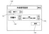
図4は、設定受付画面の内容例を説明する図である。設定受付画面140は、端子の選択インタフェース141、状況選択インタフェース142、動作内容の選択インタフェース143、及び、設定ボタン144を含む。
FIG. 4 is a diagram illustrating an example of the contents of the setting reception screen. The
端子の選択インタフェース141は、切り替えボタンを含み、切り替えボタンが選択される都度、対象の端子が巡回的に切り替わる。図4の設定受付画面140では、1つ目の「端子1」が選択されている。
The
状況選択インタフェース142は、切り替えボタンを含み、切り替えボタンが選択される都度、制御内容を実行する対象の状況が切り替わる。図4の設定受付画面140では、動作内容を実行する状況として「充電中」が選択されている。状況選択インタフェース142は、図4の例では、状況をテキスト(ここでは「充電中」)で表示して切り替えボタンで選択可能としているが、状況の識別データ(状況番号)の入力を受け付ける入力欄であってもよい。
The
動作内容の選択インタフェース143は、切り替えボタンを含み、切り替えボタンが選択される都度、対象の状況に対して設定されている動作内容が表示される。図4の設定受付画面140では、動作内容として「待機(解除から300秒後に復帰)」が選択されている。動作内容の選択インタフェース143は、図4の例では動作内容をテキスト(ここでは「待機(解除から300秒後に復帰)」で表示して切り替えボタンで選択可能としているが、動作内容の識別データ(動作内容番号)の入力を受け付ける入力欄であってもよい。
The action
設定受付画面140は、設定ボタン144を含む。設定ボタン144が選択されると、各状況に対して選択されている動作内容の設定が、制御部11のメモリに記憶される。
The
図5は、メモリに記憶される設定内容の一例の説明図である。メモリには、図5に示すように、端子の識別データに対し、充電中、給電中、及び自立給電中それぞれの識別データ(状況番号)に対応付けて動作内容の識別データ(動作内容番号)が記憶される。図5では、説明を分かり易くするために、状況及び動作内容について識別データのみならず、各状況及び制御内容を文字で示しているが、記憶されるデータは識別データでよい。 FIG. 5 is an explanatory diagram of an example of setting contents stored in the memory. As shown in Figure 5, the memory stores identification data (operation content numbers) of operation details in correspondence with identification data (status numbers) for charging, power supply, and standalone power supply for terminal identification data. is memorized. In FIG. 5, in order to make the explanation easier to understand, not only identification data but also each situation and control content are shown in characters regarding the situation and operation content, but the data to be stored may be identification data.
図5の例では、1番目の端子「端子1」に入力される信号の信号レベルがオンとなった場合、運転状況が「給電中」であるときに、待機する(信号レベルのオンが解除されてから300秒後に復帰)という動作が設定されている。1番目の端子「端子1」に入力される信号の信号レベルがオンとなった場合、運転状況が「充電中」及び「自立給電中」である場合については何も選択されておらず、即ち、信号オンに対して何もしない、との設定がされている。この場合、充電又は給電がそのまま継続する。同様に2番目の端子「端子2」に入力される信号の信号レベルがオンとなった場合、運転状況がどの状況であっても待機する(信号レベルのオンが解除されたときには即時に復帰)という動作が設定されている。 In the example shown in Figure 5, if the signal level of the signal input to the first terminal "terminal 1" turns on, the system goes into standby when the operating status is "power supply" (the signal level turns off). The operation is set to return after 300 seconds. When the signal level of the signal input to the first terminal "terminal 1" is on, nothing is selected when the operating status is "charging" and "independent power supply", i.e. , it is set to do nothing when the signal is turned on. In this case, charging or power supply continues as is. Similarly, if the signal level of the signal input to the second terminal "terminal 2" turns on, it will stand by no matter what the driving situation is (it will immediately return when the signal level is turned off). This behavior is set.
図5に示したように、端子毎、及び運転状況別に、外部信号の信号レベルがオンとなった場合の動作内容(待機、停止又は何もしない(そのままの動作を継続))が各々設定できることにより、充放電装置1は、使用状況等に応じて下記のような制御をするように設定される。
As shown in Figure 5, the operation contents (standby, stop, or do nothing (continue the same operation)) when the signal level of the external signal is turned on can be set for each terminal and operation status. Accordingly, the charging/discharging
第1の例では、充放電装置1の管理者あるいは保守担当者が、外部信号受付部17の端子の1つ目の端子に、逆電力継電器25からのRPR信号、2つ目の端子に、地絡過電圧継電器24からのOVGR信号を入力させる場合の設定について説明する。
In the first example, the administrator or maintenance person of the charging/discharging
この場合、管理者あるいは保守担当者により、図5に示した内容を設定できる。この設定では、電力系統Eと接続された状態で、逆電力が検知されてRPR信号がオンとなったことが外部信号受付部17を介して検知された場合、制御部11は、給電中であるときは、車両Vの蓄電装置30からの出力を停止する。制御部11は、充電中であるとき、逆電力は充放電装置1の制御を原因とするものではないため、何もせず、即ち、運転を停止せずそのまま継続する。待機中や停止状態である場合も同様である。制御部11は、電力系統Eと接続された状態ではない自立給電中も、何もせず、即ち、運転を停止せずそのまま継続する。このように、充放電装置1の管理者あるいは保守担当者によって、状況に応じた動作内容を設定できる。
In this case, the contents shown in FIG. 5 can be set by the administrator or the person in charge of maintenance. In this setting, when it is detected via the external
OVGR信号がオンとなったことが外部信号受付部17を介して検知された場合、制御部11は、図5に示した設定では、「充電中」、「放電中」及び「自立給電中」のいずれであっても、車両Vの蓄電装置30からの出力、運転を停止する。自立給電中の場合、電源部13の起動用蓄電池の劣化を防ぐために、運転を停止する。いずれの場合も、設定に基づき、地絡が解消されたことが検知できると、制御部11は、即座に所定のシーケンスを実行して車載制御装置32と接続処理を実行し、充放電又は自立給電をするように復帰する。
When it is detected via the external
また、第1の例において「待機(解除から即時復帰)」が設定されている場合、OVGR信号がオンとなったことが検知されると、制御部11は、「充電中」、及び「給電中(放電中)」では、車両Vの蓄電装置30からの出力を停止する。ただし、制御部11は、終了時の所定シーケンス(通信接続を切断する等)を実行することなく、接続待機状態に遷移する。接続待機状態とは、充放電装置1のDCリレー10aと車両VのDCリレー33がオンであって、充放電装置1と車載制御装置32との間の通信接続が維持されていて情報の送受信が可能であり、充放電をいつでも開始できる状態である。制御部11は、「待機(解除から即時復帰)」が設定されている場合、OVGR信号がオンとなったことが検知されたタイミングで「自立給電中」であるときには、出力を停止すると共に終了時の所定シーケンスも実行して終了し、管理者が手動で充放電装置1を復帰させるまで運転を開始しないようにする、という内容としてもよい。以下、「待機(解除から即時復帰)」に設定されている場合は同様の動作をするようにしてもよい。
Further, in the first example, when "standby (immediate return from release)" is set, when it is detected that the OVGR signal is turned on, the control unit 11 displays "charging" and "power supply". "Middle (discharging)", the output from the
第2の例では、充放電装置1の管理者あるいは保守担当者が、外部信号受付部17の端子に、外部からの接点出力信号、例えば連系装置等で異常が検知された場合の接点出力信号を入力させるケースの設定について説明する。充放電装置1の管理者あるいは保守担当者が、外部からの接点出力信号が入力されたときに出力を一時的に停止させ、即座に出力を再開させたい場合、以下のように設定する。
In the second example, the administrator or maintenance person of the charging/discharging
図6は、第2の例における設定内容の説明図である。第2の例では、1番目の端子「端子1」のみに対して設定されている。第2の例でも、1番目の端子「端子1」に入力される信号の信号レベルがオンとなった場合、運転状況がどの状況であっても待機する(信号レベルのオンが解除されたときには即時に復帰)との動作設定がされている。 FIG. 6 is an explanatory diagram of the setting contents in the second example. In the second example, it is set only for the first terminal "terminal 1". In the second example as well, if the signal level of the signal input to the first terminal "terminal 1" turns on, it will wait no matter what the driving situation is (when the signal level is turned off, The operation is set to return immediately).
第2の例では、外部からの接点出力信号がオンとなったことが外部信号受付部17を介して検知された場合、制御部11は、「充電中」、「放電中」及び「自立給電中」のいずれであっても、車両Vの蓄電装置30からの出力、運転を停止する。充放電装置1の管理者あるいは保守担当者が、外部からの接点出力信号が入力されたときに出力を一時的に停止させ、接点出力信号がオフとなった場合に即時復帰させるように制御することが可能になる。
In the second example, when it is detected via the external
第3の例では、充放電装置1の管理者あるいは保守担当者が、外部信号受付部17の端子に、外部からの接点出力信号、例えば連系装置等で異常が検知された場合の接点出力信号を入力させるケースでの他の設定について説明する。第3の例では、充放電装置1の管理者あるいは保守担当者が、何らかの状況でオンとなるスイッチを増設し、そのスイッチの出力を外部信号受付部17の端子に入力させる場合を併せて説明する。充放電装置1の管理者あるいは保守担当者が、外部からの接点出力信号が入力された場合に、充電のみを一時的に停止させ、増設したスイッチがオンとなった場合に異常停止させるようにしたいときには、以下のように設定する。
In the third example, the administrator or maintenance person of the charging/discharging
図7は、第3の例における設定内容の説明図である。第3の例では、1番目の端子「端子1」に入力される信号の信号レベルがオンとなった場合、運転状況が「充電中」であるときに、待機する(信号レベルのオンが解除されたときには即時に復帰)との動作内容が設定されている。1番目の端子「端子1」に入力される信号の信号レベルがオンとなった場合、運転状況が「給電中」及び「自立給電中」であるときには、何もしない、即ち運転を停止しない、との設定がされている。そして2番目の端子「端子2」に入力される信号の信号レベルがオンとなった場合、運転状況がどの状況であっても異常停止するとの動作内容が設定されている。 FIG. 7 is an explanatory diagram of the setting contents in the third example. In the third example, if the signal level of the signal input to the first terminal "terminal 1" turns on, the system will wait when the driving status is "charging" (the signal level turns off). The operation content is set to ``immediately return when the When the signal level of the signal input to the first terminal "terminal 1" is on, and the operating status is "power supplying" or "self-sustaining power supply", do nothing, that is, do not stop operation. The settings have been made. The operation content is set such that when the signal level of the signal input to the second terminal "terminal 2" is turned on, an abnormal stop occurs regardless of the operating condition.
第3の例では、外部からの接点出力信号がオンとなったことが外部信号受付部17を介して検知された場合、制御部11は、「充電中」のみ一時的に、充放電装置1を待機状態に遷移させ、その他の状況時には何もしない。そして接点出力信号がオフとなった場合、制御部11は、所定のシーケンスを実行して車載制御装置32と接続処理を実行し、充電を再開するように復帰する。
In the third example, when it is detected via the external
増設されたスイッチがオンとなったことが外部信号受付部17を介して検知された場合、制御部11は、図7に示した設定では、「充電中」、「放電中」及び「自立給電中」のいずれであっても、車両Vの蓄電装置30からの出力、運転を異常停止させる。このようにして何らかの状態になった場合には、異常停止させる、という設定が可能である。
When it is detected via the external
充放電装置1は、図5-図7に示したような設定内容が可能であるため、外部信号受付部17で受け付けている信号の信号レベルがオンになったときに、制御部11が、運転状況に応じてどのような制御をするかを、多様な組み合わせで設定可能である。
Since the charging/discharging
(変形例)
なお、外部信号受付部17にて複数の信号を受け付けることができる以上、それらの複数の信号がオンとなることが想定される場合、どちらの動作内容を優先すべきかの設定が必要である。図8は、優先順位の設定例を示す図である。図8は、図5に示した動作内容の設定に、更に優先順位の設定が加えられた例を示している。図8の例では、1つ目の端子及び2つ目の端子それぞれに入力された信号がいずれもオンとなった場合、2つ目の端子に入力される信号に基づく動作内容を優先する。なお優先順位の設定は、設定受付画面140の選択インタフェース141にて端子の選択を受け付ける際に(S101)、共に優先順位に対応する数値の入力を受け付けることによって達成するとよい。
(Modified example)
Note that since the external
若しくは、動作内容それぞれについて優先順位が設定可能であってもよい。図9は、動作内容毎の優先順位を示す図である。図9の例では、動作内容の5つ目の選択肢として「緊急停止」が加えられており、「緊急停止」という動作内容が最も優先順位が高く設定されている。図9に示す例がデフォルトとして設定されているとよい。次に「異常停止」、「正常停止」の順に優先順位が設定され、更に「待機(解除から300秒後に復帰)」、「待機(解除から即時復帰)」の順に優先順位が設定されている。 Alternatively, it may be possible to set priorities for each operation content. FIG. 9 is a diagram showing priorities for each operation content. In the example of FIG. 9, "Emergency stop" is added as the fifth option of the operation content, and the action content "Emergency stop" is set with the highest priority. It is preferable that the example shown in FIG. 9 be set as a default. Next, priorities are set in the order of "abnormal stop" and "normal stop", and further priorities are set in the order of "standby (recovery 300 seconds after release)" and "standby (immediate return from release)". .
「緊急停止」の動作内容は、DCリレー10a及びDCリレー33を即時オフとし、充放電の出力の降下速度を速めて直ちに出力停止とし、充放電装置1と車載制御装置32との間の通信接続も切断する。「緊急停止」の場合、ユーザの手動により復帰操作がされるまでは終了したままとする。その他「**停止」は、充放電装置1と車載制御装置32との間の通信接続は維持したまま、出力を停止する。図10の例のように設定されている場合、動作内容として、1つ目の端子に対して「充電中」に「待機(解除から即時復帰)」が設定され、2つ目の端子に対して「充電中」に「緊急停止」が設定されていると、制御部11は以下のように動作する。充電中に、いずれの端子に入力されている信号もオンとなった場合、制御部11は、それぞれに設定されている動作内容を参照し、優先順位が高い方の動作内容、例えば「緊急停止」を実施する。優先順位を設けることにより、外部信号受付部17を、複数の信号をそれぞれ入力できる構成としたとしても、安全に適切に動作させることが可能になる。
The operation details of the "emergency stop" are to immediately turn off the
(第2実施形態)
第2実施形態では、充放電装置1は、外部信号受付部17に受け付けている信号に基づく「充電中」、「給電中」及び「自立給電中」の状況別の動作内容の設定を、その状況が、どのような操作等に基づくものなのかによって区別して受け付ける。第2実施形態における充放電システム200の構成は、後述する設定処理及び設定に基づく制御を除いて、第1実施形態の充放電システム200と同様である。したがって、共通する構成については同一の符号を付して詳細な説明を省略する。
(Second embodiment)
In the second embodiment, the charging/discharging
図10は、第2実施形態における設定受付手順の一例を示すフローチャートである。充放電装置1の操作部14のディスプレイに表示されている操作画面に対し、管理者あるいは保守担当者が設定メニューのオプション設定を選択すると、以下の処理が開始される。
FIG. 10 is a flowchart illustrating an example of a setting acceptance procedure in the second embodiment. When an administrator or a maintenance person selects an option setting in a setting menu on the operation screen displayed on the display of the
充放電装置1の制御部11は、外部信号受付部17の2つの端子のいずれかの選択を受け付ける(ステップS201)。ステップS201において制御部11は、外部信号受付部17が含む端子の数に応じて、何番目なのかの選択を受け付ける。
The control unit 11 of the charging/discharging
制御部11は、選択された端子に対する信号レベルの設定対象の運転内容の選択を受け付ける(ステップS202)。ステップS202において制御部11は、充放電装置1で選択できる運転内容のいずれかの選択を受け付ける。運転内容は、例えば、操作部14で充電を指定してスタートさせる「充電運転」、操作部14で給電を指定してスタートさせる「給電運転」、自立給電を指定してスタートさせる「自立運転」を含む。運転内容は更に、充電又は給電を時刻と共に予約する「予約運転」、及び、上位装置29からの指示に応じて充電又は給電を実施させる「EMS運転」を含む。運転内容は更に、制御部11自身の制御によって充電及び給電を適宜実施する「出力自律運転」、及び、課金に応じて充電を実行する「課金充電運転」を含む。ステップS202において制御部11は、運転内容の識別データ(運転内容番号)をそのまま受け付けてもよい。
The control unit 11 receives the selection of the operation details for which the signal level for the selected terminal is to be set (step S202). In step S<b>202 , the control unit 11 receives a selection of any of the operation details that can be selected by the charging/discharging
制御部11は、選択された運転内容毎に、後述の動作内容を実行する状況を「充電中」、「給電中」及び「自立給電中」のいずれかを選択する(ステップS203)。ステップS203において制御部11は、選択された運転内容が「充電運転」の場合、「充電中」のみを選択肢とし、他を選択させないようにしてもよい。同様にして、「給電運転」が選択されている場合には「給電中」のみが選択肢となり、「自立運転」が選択されている場合には「自立給電中」のみが選択肢となるようにしてもよい。「予約運転」が選択されている場合、制御部11はステップS203において「充電中」又は「給電中」の選択を受け付け、「自立給電中」の選択は受け付けない。同様にして「EMS運転」及び「出力自律運転」の選択がされている場合、制御部11は、「充電中」又は「給電中」の選択を受け付け、「自立給電中」の選択は受け付けない。「課金充電運転」が選択されている場合、制御部11は、「充電中」のみの選択を受け付ける。ステップS203において制御部11は、状況の識別データ(状況番号)をそのまま受け付けてもよい。 The control unit 11 selects one of "charging", "power supply", and "self-sustaining power supply" as the situation in which the operation content described below is executed for each selected operation content (step S203). In step S203, when the selected operation content is "charging operation," the control unit 11 may select only "charging" and not allow others to be selected. Similarly, when "power feeding operation" is selected, "power supplying" is the only option, and when "standalone operation" is selected, "independent power supply" is the only option. Good too. If "reserved operation" is selected, the control unit 11 accepts the selection of "charging" or "power supply" in step S203, but does not accept the selection of "independent power supply". Similarly, when "EMS operation" and "output autonomous operation" are selected, the control unit 11 accepts the selection of "charging" or "power supply", but does not accept the selection of "self-sustained power supply". . When "charged charging operation" is selected, the control unit 11 accepts selection of only "charging". In step S203, the control unit 11 may accept the situation identification data (situation number) as is.
制御部11は、選択された状況において、端子に入力される信号の信号レベルがオンとなった場合の動作内容の選択を受け付ける(ステップS204)。選択対象の動作内容は、第1実施形態では、第1に「待機(解除から300秒後に復帰)」、第2に「待機(解除から即時復帰)」、第3に「正常停止」、第4に「異常停止」、第5に「何もしない」である。動作内容は、これに限られず、復帰までの時間は300秒に限らないし、6つ以上の選択対象があってもよい。ステップS204において制御部11は、動作内容の識別データ(動作内容番号)をそのまま受け付けてもよい。 In the selected situation, the control unit 11 accepts the selection of the operation content when the signal level of the signal input to the terminal is turned on (step S204). In the first embodiment, the operation contents to be selected are: 1st, "standby (returns after 300 seconds from release)", 2nd, "standby (immediate return from release)", 3rd, "normal stop", The fourth option is "abnormal stop" and the fifth option is "do nothing." The content of the operation is not limited to this, the time until recovery is not limited to 300 seconds, and there may be six or more selection targets. In step S204, the control unit 11 may accept the identification data (action content number) of the action content as is.
制御部11は、選択された端子の識別データに対応付けて、選択された運転内容の識別データ(運転内容番号)別に、運転状況の識別データ(状況番号)毎に選択された動作内容の識別データ(動作内容番号)をメモリに記憶し(ステップS205)、設定受付手順を終了する。 The control unit 11 identifies the selected operation content for each driving status identification data (situation number) in association with the identification data of the selected terminal. The data (operation content number) is stored in the memory (step S205), and the setting reception procedure is ended.
図11は、第2実施形態の設定受付画面140の内容例を説明する図である。設定受付画面140は、端子の選択インタフェース141、運転内容選択インタフェース146、状況選択インタフェース142、動作内容の選択インタフェース143、及び、設定ボタン144を含む。端子の選択インタフェース141、状況選択インタフェース142、及び、動作内容の選択インタフェース143については、図4の説明図で選択した内容と同様であるから詳細な説明を省略する。
FIG. 11 is a diagram illustrating an example of the contents of the
第2実施形態では、運転内容選択インタフェース146にて、運転内容の選択が受け付け可能である。運転内容選択インタフェース146は切り替えボタンを含み、切り替えボタンが選択される都度、運転内容が切り替わる。図11の設定受付画面140では、運転内容として「予約運転」が選択されている。運転内容選択インタフェース146は、運転内容の識別データ(運転内容番号)の入力を受け付ける入力欄であってもよい。
In the second embodiment, the driving
第2実施形態の設定受付画面においても、設定ボタン144が選択されると、端子別に、運転内容及び各状況に対して選択されている動作内容の設定が、制御部11のメモリに記憶される。
Also on the setting reception screen of the second embodiment, when the
図12は、第2実施形態でメモリに記憶される設定内容の一例の説明図である。メモリには、図12に示すように、端子の識別データに対し、運転内容別に、充電中、給電中、及び自立給電中それぞれの識別データ(状況番号)に対応付けて動作内容の識別データ(動作内容番号)が記憶される。図12の例では、1番目の端子「端子1」のみについて、設定されている。図12の例では運転内容が「充電運転」で、運転状況が「充電中」である場合に、1番目の端子に入力される信号の信号レベルがオンとなったときには、[2]との動作設定がされている。[2]は、待機する(信号レベルのオンが解除されてから即時復帰)との動作設定である。運転内容が「給電運転」で運転状況が「給電中」である場合は[1]と設定されている。[1]は、待機する(信号レベルのオンが解除されてから300秒後に復帰)という動作設定である。そして、運転内容が「自立運転」で運転状況が「自立」である場合には、[3]と設定されている。[3]は、正常停止である。 FIG. 12 is an explanatory diagram of an example of setting contents stored in the memory in the second embodiment. As shown in FIG. 12, the memory stores operation content identification data (status numbers) in correspondence with identification data (status numbers) for charging, power supply, and standalone power supply for each operation content, with respect to terminal identification data. The operation content number) is stored. In the example of FIG. 12, only the first terminal "terminal 1" is set. In the example of Fig. 12, when the operation content is "charging operation" and the operation status is "charging", when the signal level of the signal input to the first terminal turns on, the The operation settings have been made. [2] is an operation setting of waiting (immediate return after the signal level is turned off). If the operation content is "power supply operation" and the operation status is "power supply in progress", it is set to [1]. [1] is an operation setting of waiting (returning 300 seconds after the signal level is turned off). When the driving content is "independent driving" and the driving status is "independent", [3] is set. [3] is a normal stop.
同様にして図12の例では、「予約運転」で運転中に運転状況が「充電中」である場合に、1番目の端子に入力される信号の信号レベルがオンとなったときには、[2]に設定されており、「給電中」である場合には、[1]に設定されている。「EMS運転」で運転中も、「出力自律運転」で運転中も、「予約運転」で運転中と同様である。これに対し、図12の例では「課金充電運転」で運転状況が「充電中」である場合に、1番目の端子に入力される信号の信号レベルがオンとなったときには、[3]と設定されている。 Similarly, in the example of FIG. 12, when the driving status is "charging" during "reserved operation" and the signal level of the signal input to the first terminal turns on, [2 ], and when it is “power feeding”, it is set to [1]. The same applies to driving in "EMS operation", "output autonomous operation", and "reserved operation". On the other hand, in the example of FIG. 12, when the driving status is "charging" in "charging charging operation" and the signal level of the signal input to the first terminal turns on, [3] It is set.
充放電装置1で上述したように、運転内容及び状況別に動作内容の設定を受け付けることができるため、充放電装置1の管理者又は保守作業者は、外部信号受付部17の1つ目の端子に地絡過電圧継電器24からOVGR信号を入力させ、図12のように、OVGR信号がオンの場合に給電中であったときには出力を停止し、OVGR信号が復帰(オフ)してから所定時間(300秒)後に自動的に復帰する、という動作を行なうように設定できる。更に、充電中の場合は、そして充放電装置1の管理者又は保守作業者は、課金充電運転の場合には、OVGR信号がオンの場合には正常停止するように設定できる。
As described above for the charging/discharging
図13は、第2実施形態でメモリに記憶される設定内容の他の一例の説明図である。図13では、図12と同様に、メモリには、端子の識別データに対し、運転内容別に、充電中、給電中、及び自立給電中それぞれの識別データ(状況番号)に対応付けて動作内容の識別データ(動作内容番号)が記憶される。図13の例では、1番目の端子「端子1」のみについて、設定されている。図13の例では運転内容が「充電運転」で、運転状況が「充電中」である場合に、1番目の端子に入力される信号の信号レベルがオンとなったときには、[2]と設定がされている。そして運転内容が「給電運転」で運転状況が「給電中」である場合も[2]と設定されている。そして、運転内容が「自立運転」で運転状況が「自立」である場合には、[3]と設定されている。[3]は、正常停止である。 FIG. 13 is an explanatory diagram of another example of setting contents stored in the memory in the second embodiment. In FIG. 13, as in FIG. 12, the memory stores information about the operation contents in correspondence with the terminal identification data (status number) for charging, power supply, and independent power supply for each operation content. Identification data (action content number) is stored. In the example of FIG. 13, only the first terminal "terminal 1" is set. In the example in Figure 13, when the operation content is "charging operation" and the operation status is "charging", when the signal level of the signal input to the first terminal turns on, it is set to [2]. is being done. Also, when the operation content is "power supply operation" and the operation status is "power supply in progress", it is set to [2]. When the driving content is "independent driving" and the driving status is "independent", [3] is set. [3] is a normal stop.
更に図13の例では、「予約運転」で運転中に運転状況が「充電中」である場合も「給電中」である場合も、1番目の端子に入力される信号の信号レベルがオンとなったときには、[2]に設定されている。「EMS運転」で運転中も、「出力自律運転」で運転中も、「予約運転」で運転中と同様である。そして図13の例では「課金充電運転」で運転状況が「充電中」である場合に、1番目の端子に入力される信号の信号レベルがオンとなったときには、[3]と設定されている。 Furthermore, in the example shown in Fig. 13, the signal level of the signal input to the first terminal is on even if the operating status is "charging" or "power supplying" during "reserved operation". When this happens, it is set to [2]. The same applies to driving in "EMS operation", "output autonomous operation", and "reserved operation". In the example of FIG. 13, when the driving status is "charging" in "charging charging operation" and the signal level of the signal input to the first terminal turns on, it is set to [3]. There is.
図13のような設定が可能であるため、充放電装置1の管理者又は保守作業者は、外部信号受付部17の1つ目の端子に他の装置からの出力停止信号を入力させ、図13のように、出力停止信号がオンの場合には出力を停止し、復帰(オフ)してから所定時間(300秒)後に自動的に復帰する、という動作を行なうように設定できる。更に、充電中の場合は、そして充放電装置1の管理者又は保守作業者は、課金充電運転の場合には、OVGR信号がオンの場合には正常停止するように設定できる。
Since settings as shown in FIG. 13 are possible, the administrator or maintenance worker of the charging/discharging
図14は、第2実施形態でメモリに記憶される設定内容の他の一例の説明図である。図14では、図12と同様に、メモリには、端子の識別データに対し、運転内容別に、充電中、給電中、及び自立給電中それぞれの識別データ(状況番号)に対応付けて動作内容の識別データ(動作内容番号)が記憶される。図14の例では、1番目の端子「端子1」のみについて、設定されている。図14の例では運転内容が「出力自律運転」で、運転状況が「給電中」である場合のみ、1番目の端子に入力される信号の信号レベルがオンとなったときに[2]と設定がされ、他の運転内容、他の状況では「空白」即ち、何もしない、そのまま動作を継続する、ということが設定されている。 FIG. 14 is an explanatory diagram of another example of setting contents stored in the memory in the second embodiment. In FIG. 14, similar to FIG. 12, the memory stores information about the operation contents in correspondence with the identification data (status number) for charging, power supply, and standalone power supply for each operation type, for each terminal identification data. Identification data (action content number) is stored. In the example of FIG. 14, only the first terminal "terminal 1" is set. In the example in Figure 14, only when the operation content is "output autonomous operation" and the operation status is "power supply", when the signal level of the signal input to the first terminal turns on, [2] is displayed. In other operation contents and other situations, it is set to be "blank", that is, to do nothing and continue operation as is.
図14のような設定が可能であるため、充放電装置1の管理者又は保守作業者は、外部信号受付部17の1つ目の端子に、増設したスイッチからの信号を入力させ、図14のように、スイッチがオンの場合には、出力自律運転中であって且つ給電中であるときには出力を停止(復帰(オフ)してから所定時間(300秒)後に自動的に復帰)する、という動作を行なうように設定できる。例えば、充放電装置1の管理者又は保守作業者は、スイッチを、できれば給電に使用したくない時間帯にオンとしておくものとして用意し、出力自律運転中にスイッチがオンの場合には、給電中であっても出力を停止する(待機)、と設定することができる。
Since the settings shown in FIG. 14 are possible, the administrator or maintenance worker of the charging/discharging
このように、第1実施形態及び第2実施形態の充放電装置1は、端子に入力される外部信号と、その信号がオンであるか否かによって充放電装置1にさせたい動作内容を、充電中又は給電中等の状況別に、管理者又は保守作業者によって選択可能とする。これにより、各充放電装置1の設置場所における他の装置との接続関係等の使用環境に応じて、動作を選択することができる。管理者(ユーザ)が適宜、増設スイッチを設けてこのスイッチのオン及びオフに応じた待機や停止の動作内容を決定できる。予め設定により、状況に応じて出力を停止しつつ、自動に復帰も可能である。一旦、待機とする処理によって車両VのDCリレー33の頻回のオン及びオフを回避してDCリレー33の消耗速度を緩めることができる。OVGR信号、RPR信号等の継電器等からの外部停止信号に基づいて停止とすることも選択でき、その場合、車両V側でも停止状態となるため、蓄電装置30及びバッテリの電力消耗を抑えることも可能である。
In this way, the charging/discharging
上述のように開示された実施の形態は全ての点で例示であって、制限的なものではない。本発明の範囲は、特許請求の範囲によって示され、特許請求の範囲と均等の意味及び範囲内での全ての変更が含まれる。 The embodiments disclosed above are illustrative in all respects and are not restrictive. The scope of the present invention is indicated by the claims, and includes all changes within the meaning and range equivalent to the claims.
1 充放電装置
11 制御部
12 車両通信部
14 操作部
17 外部信号受付部
1P,9P コンピュータプログラム
24 地絡過電圧継電器
25 逆電力継電器
30 蓄電装置
32 車載制御装置
V 車両
1 Charging and discharging device 11
Claims (7)
前記充放電装置は、前記車両に搭載される機器を除く機器から1又は複数の信号を受け付ける外部信号受付部を備え、
前記制御部は、
前記外部信号受付部で受け付ける1又は複数の信号のオンが検知された場合の前記充放電装置の待機、及び停止を含む動作内容の設定を、前記1又は複数の信号別に、充電中、放電中及び自立給電中を含む運転状況毎に受け付け、
受け付けた動作内容の設定を、前記1又は複数の信号別に、運転状況毎に記憶しておき、
前記外部信号受付部で受け付ける1又は複数の信号のオンが検知された場合、記憶してある設定に従って動作させる
充放電装置。 A charging/discharging device that is connected to a storage battery provided in a vehicle and includes a control unit that controls charging and discharging between the storage battery and a power source or a load,
The charging/discharging device includes an external signal receiving unit that receives one or more signals from devices other than devices mounted on the vehicle,
The control unit includes:
Settings of operation contents including standby and stop of the charging/discharging device when one or more signals received by the external signal reception unit are detected to be on are set for each of the one or more signals during charging and discharging. We accept requests for each operating situation, including during stand-alone power supply.
The received operation content settings are stored for each driving situation for each of the one or more signals,
The charging/discharging device operates according to the stored settings when one or more signals accepted by the external signal receiving section are detected to be on.
請求項1に記載の充放電装置。 The control unit accepts a selection of not doing anything, in addition to standby and stop, as the setting of the operation content.
The charging/discharging device according to claim 1.
請求項1又は2に記載の充放電装置。 The charging/discharging device according to claim 1 or 2, wherein the external signal reception unit receives a plurality of external stop signals output from a relay.
請求項1又は2に記載の充放電装置。 The charging/discharging device according to claim 1 or 2, wherein the external signal receiving section receives a contact output signal.
請求項1又は2に記載の充放電装置。 The charging/discharging device according to claim 1 or 2, wherein the external signal receiving section receives an output from an external switch.
前記充放電装置は、前記充放電装置は、前記車両に搭載される機器を除く機器から1又は複数の信号を受け付ける外部信号受付部を備え、
前記充放電装置の制御部は、
前記外部信号受付部で受け付ける1又は複数の信号のオンが検知された場合の前記充放電装置の待機、及び停止を含む動作内容の設定を、前記1又は複数の信号別に、充電中、放電中及び自立給電中を含む運転状況毎に受け付け、
受け付けた動作内容の設定を、前記1又は複数の信号別に、運転状況毎に記憶しておき、
前記外部信号受付部で受け付ける1又は複数の信号のオンが検知された場合、記憶してある設定に従って動作させる
充放電制御方法。 A method for controlling a charging/discharging device that is connected to a storage battery provided in a vehicle and controls charging and discharging between the storage battery and a power source or a load, the method comprising:
The charging and discharging device includes an external signal reception unit that receives one or more signals from devices other than devices installed in the vehicle,
The control unit of the charging/discharging device includes:
Settings of operation contents including standby and stop of the charging/discharging device when one or more signals received by the external signal reception unit are detected to be on are set for each of the one or more signals during charging and discharging. We accept requests for each operating situation, including during stand-alone power supply.
The received operation content settings are stored for each driving situation for each of the one or more signals,
A charging/discharging control method comprising: operating according to stored settings when one or more signals received by the external signal receiving section are detected to be on.
前記車両に搭載される機器を除く機器から1又は複数の信号を受け付ける外部信号受付部で受け付ける1又は複数の信号のオンが検知された場合の前記充放電装置の待機、及び停止を含む動作内容の設定を、前記1又は複数の信号別に、充電中、放電中及び自立給電中を含む運転状況毎に受け付け、
受け付けた動作内容の設定を、前記1又は複数の信号別に、運転状況毎に記憶しておき、
前記外部信号受付部で受け付ける1又は複数の信号のオンが検知された場合、記憶してある設定に従って動作するよう制御する
処理を実行させるコンピュータプログラム。 A computer installed in a charging/discharging device that is connected to a storage battery installed in a vehicle and controls charging and discharging between the storage battery and a power source or load,
Operation details including standby and stop of the charging/discharging device when one or more signals received by an external signal reception unit that receives one or more signals from equipment other than equipment mounted on the vehicle is detected to be on. Accept settings for each driving situation including charging, discharging, and independent power supply for each of the one or more signals,
The received operation content settings are stored for each driving situation for each of the one or more signals,
A computer program that executes a process of controlling operations according to stored settings when one or more signals received by the external signal reception section are detected to be on.
Priority Applications (1)
| Application Number | Priority Date | Filing Date | Title |
|---|---|---|---|
| JP2022080375A JP7459893B2 (en) | 2022-05-16 | 2022-05-16 | Charge/discharge device, charge/discharge control method, and computer program |
Applications Claiming Priority (1)
| Application Number | Priority Date | Filing Date | Title |
|---|---|---|---|
| JP2022080375A JP7459893B2 (en) | 2022-05-16 | 2022-05-16 | Charge/discharge device, charge/discharge control method, and computer program |
Publications (2)
| Publication Number | Publication Date |
|---|---|
| JP2023168963A true JP2023168963A (en) | 2023-11-29 |
| JP7459893B2 JP7459893B2 (en) | 2024-04-02 |
Family
ID=88923432
Family Applications (1)
| Application Number | Title | Priority Date | Filing Date |
|---|---|---|---|
| JP2022080375A Active JP7459893B2 (en) | 2022-05-16 | 2022-05-16 | Charge/discharge device, charge/discharge control method, and computer program |
Country Status (1)
| Country | Link |
|---|---|
| JP (1) | JP7459893B2 (en) |
Family Cites Families (6)
| Publication number | Priority date | Publication date | Assignee | Title |
|---|---|---|---|---|
| JP6045450B2 (en) | 2013-07-02 | 2016-12-14 | 株式会社椿本チエイン | Power control device |
| MY164830A (en) | 2014-12-26 | 2018-01-30 | Hitachi Ltd | Power Supply System and Power Supply Method |
| JP6931797B2 (en) | 2017-06-01 | 2021-09-08 | パナソニックIpマネジメント株式会社 | Control systems, control methods, and control programs |
| JP6913871B2 (en) | 2017-12-27 | 2021-08-04 | パナソニックIpマネジメント株式会社 | Control command system and power converter |
| JP2020061850A (en) | 2018-10-09 | 2020-04-16 | 鈴木電機株式会社 | Power generation control system, power generation control method, and program |
| US11011913B2 (en) | 2019-01-25 | 2021-05-18 | Flex Power Control, Inc. | Multifunction power management system |
-
2022
- 2022-05-16 JP JP2022080375A patent/JP7459893B2/en active Active
Also Published As
| Publication number | Publication date |
|---|---|
| JP7459893B2 (en) | 2024-04-02 |
Similar Documents
| Publication | Publication Date | Title |
|---|---|---|
| JP7160074B2 (en) | Charge/discharge device, charge/discharge control method, and computer program | |
| JP5126297B2 (en) | Power management system and in-vehicle power management device | |
| KR101437019B1 (en) | Power feed system for electric vehicle | |
| JP2009296824A (en) | Charging system | |
| CN107444123B (en) | Power supply device, power supply method and electric vehicle | |
| JP2021100322A (en) | Charge/discharge device, charge/discharge system, charge/discharge control method, and computer program | |
| CN111264012B (en) | Method for black start of energy supply device, bi-directional inverter and energy supply device with bi-directional inverter | |
| JP2022098972A (en) | Server, electric power management method | |
| JP2017117673A (en) | Power controller, power control method and fuel cell system | |
| JP6504101B2 (en) | Power controller | |
| JP7459893B2 (en) | Charge/discharge device, charge/discharge control method, and computer program | |
| US11764584B1 (en) | Multipurpose inverter with flexible ports | |
| EP4258506A1 (en) | Charging and discharging device, charge/discharge control method, and computer program | |
| JP2020031484A (en) | Power storage system and power conditioner | |
| JP2018064431A (en) | Power control unit | |
| JP7184487B2 (en) | building power supply system | |
| JP7571513B2 (en) | CHARGING/DISCHARGING DEVICE, CHARGING/DISCHARGING CONTROL METHOD, AND COMPUTER PROGRAM | |
| JP2016092849A (en) | Power supply system, start-up control device and method for controlling power supply system | |
| CN220754426U (en) | Energy storage system and energy storage device | |
| CN112389215B (en) | Charging and discharging circuit structure, charging and discharging equipment, charging and discharging system and charging and discharging method | |
| JP7365950B2 (en) | fuel cell equipment | |
| JP2023164009A (en) | Charging/discharging device, charging/discharging device control method, and computer program | |
| EP4206033A1 (en) | Battery swapping station with emergency power generation function | |
| JP2023182452A (en) | Charge/discharge device and charge/discharge control method | |
| JP2023059643A (en) | EV charging system |
Legal Events
| Date | Code | Title | Description |
|---|---|---|---|
| A621 | Written request for application examination |
Free format text: JAPANESE INTERMEDIATE CODE: A621 Effective date: 20230123 |
|
| A977 | Report on retrieval |
Free format text: JAPANESE INTERMEDIATE CODE: A971007 Effective date: 20240205 |
|
| TRDD | Decision of grant or rejection written | ||
| A01 | Written decision to grant a patent or to grant a registration (utility model) |
Free format text: JAPANESE INTERMEDIATE CODE: A01 Effective date: 20240220 |
|
| A61 | First payment of annual fees (during grant procedure) |
Free format text: JAPANESE INTERMEDIATE CODE: A61 Effective date: 20240304 |
|
| R150 | Certificate of patent or registration of utility model |
Ref document number: 7459893 Country of ref document: JP Free format text: JAPANESE INTERMEDIATE CODE: R150 |