JP2022520017A - Endoscope device - Google Patents
Endoscope device Download PDFInfo
- Publication number
- JP2022520017A JP2022520017A JP2021543206A JP2021543206A JP2022520017A JP 2022520017 A JP2022520017 A JP 2022520017A JP 2021543206 A JP2021543206 A JP 2021543206A JP 2021543206 A JP2021543206 A JP 2021543206A JP 2022520017 A JP2022520017 A JP 2022520017A
- Authority
- JP
- Japan
- Prior art keywords
- endoscope
- flexible
- sheath
- tube
- passage
- Prior art date
- Legal status (The legal status is an assumption and is not a legal conclusion. Google has not performed a legal analysis and makes no representation as to the accuracy of the status listed.)
- Granted
Links
Images


Classifications
-
- A—HUMAN NECESSITIES
- A61—MEDICAL OR VETERINARY SCIENCE; HYGIENE
- A61B—DIAGNOSIS; SURGERY; IDENTIFICATION
- A61B1/00—Instruments for performing medical examinations of the interior of cavities or tubes of the body by visual or photographical inspection, e.g. endoscopes; Illuminating arrangements therefor
- A61B1/06—Instruments for performing medical examinations of the interior of cavities or tubes of the body by visual or photographical inspection, e.g. endoscopes; Illuminating arrangements therefor with illuminating arrangements
- A61B1/0661—Endoscope light sources
- A61B1/0676—Endoscope light sources at distal tip of an endoscope
-
- A—HUMAN NECESSITIES
- A61—MEDICAL OR VETERINARY SCIENCE; HYGIENE
- A61B—DIAGNOSIS; SURGERY; IDENTIFICATION
- A61B1/00—Instruments for performing medical examinations of the interior of cavities or tubes of the body by visual or photographical inspection, e.g. endoscopes; Illuminating arrangements therefor
- A61B1/00142—Instruments for performing medical examinations of the interior of cavities or tubes of the body by visual or photographical inspection, e.g. endoscopes; Illuminating arrangements therefor with means for preventing contamination, e.g. by using a sanitary sheath
-
- A—HUMAN NECESSITIES
- A61—MEDICAL OR VETERINARY SCIENCE; HYGIENE
- A61B—DIAGNOSIS; SURGERY; IDENTIFICATION
- A61B1/00—Instruments for performing medical examinations of the interior of cavities or tubes of the body by visual or photographical inspection, e.g. endoscopes; Illuminating arrangements therefor
- A61B1/00002—Operational features of endoscopes
- A61B1/00025—Operational features of endoscopes characterised by power management
- A61B1/00027—Operational features of endoscopes characterised by power management characterised by power supply
-
- A—HUMAN NECESSITIES
- A61—MEDICAL OR VETERINARY SCIENCE; HYGIENE
- A61B—DIAGNOSIS; SURGERY; IDENTIFICATION
- A61B1/00—Instruments for performing medical examinations of the interior of cavities or tubes of the body by visual or photographical inspection, e.g. endoscopes; Illuminating arrangements therefor
- A61B1/00064—Constructional details of the endoscope body
- A61B1/00103—Constructional details of the endoscope body designed for single use
-
- A—HUMAN NECESSITIES
- A61—MEDICAL OR VETERINARY SCIENCE; HYGIENE
- A61B—DIAGNOSIS; SURGERY; IDENTIFICATION
- A61B1/00—Instruments for performing medical examinations of the interior of cavities or tubes of the body by visual or photographical inspection, e.g. endoscopes; Illuminating arrangements therefor
- A61B1/00131—Accessories for endoscopes
- A61B1/00135—Oversleeves mounted on the endoscope prior to insertion
-
- A—HUMAN NECESSITIES
- A61—MEDICAL OR VETERINARY SCIENCE; HYGIENE
- A61B—DIAGNOSIS; SURGERY; IDENTIFICATION
- A61B1/00—Instruments for performing medical examinations of the interior of cavities or tubes of the body by visual or photographical inspection, e.g. endoscopes; Illuminating arrangements therefor
- A61B1/005—Flexible endoscopes
- A61B1/0051—Flexible endoscopes with controlled bending of insertion part
- A61B1/0052—Constructional details of control elements, e.g. handles
-
- A—HUMAN NECESSITIES
- A61—MEDICAL OR VETERINARY SCIENCE; HYGIENE
- A61B—DIAGNOSIS; SURGERY; IDENTIFICATION
- A61B1/00—Instruments for performing medical examinations of the interior of cavities or tubes of the body by visual or photographical inspection, e.g. endoscopes; Illuminating arrangements therefor
- A61B1/005—Flexible endoscopes
- A61B1/0051—Flexible endoscopes with controlled bending of insertion part
- A61B1/0055—Constructional details of insertion parts, e.g. vertebral elements
-
- A—HUMAN NECESSITIES
- A61—MEDICAL OR VETERINARY SCIENCE; HYGIENE
- A61B—DIAGNOSIS; SURGERY; IDENTIFICATION
- A61B1/00—Instruments for performing medical examinations of the interior of cavities or tubes of the body by visual or photographical inspection, e.g. endoscopes; Illuminating arrangements therefor
- A61B1/04—Instruments for performing medical examinations of the interior of cavities or tubes of the body by visual or photographical inspection, e.g. endoscopes; Illuminating arrangements therefor combined with photographic or television appliances
- A61B1/05—Instruments for performing medical examinations of the interior of cavities or tubes of the body by visual or photographical inspection, e.g. endoscopes; Illuminating arrangements therefor combined with photographic or television appliances characterised by the image sensor, e.g. camera, being in the distal end portion
- A61B1/053—Instruments for performing medical examinations of the interior of cavities or tubes of the body by visual or photographical inspection, e.g. endoscopes; Illuminating arrangements therefor combined with photographic or television appliances characterised by the image sensor, e.g. camera, being in the distal end portion being detachable
-
- A—HUMAN NECESSITIES
- A61—MEDICAL OR VETERINARY SCIENCE; HYGIENE
- A61B—DIAGNOSIS; SURGERY; IDENTIFICATION
- A61B1/00—Instruments for performing medical examinations of the interior of cavities or tubes of the body by visual or photographical inspection, e.g. endoscopes; Illuminating arrangements therefor
- A61B1/06—Instruments for performing medical examinations of the interior of cavities or tubes of the body by visual or photographical inspection, e.g. endoscopes; Illuminating arrangements therefor with illuminating arrangements
- A61B1/0661—Endoscope light sources
- A61B1/0684—Endoscope light sources using light emitting diodes [LED]
-
- A—HUMAN NECESSITIES
- A61—MEDICAL OR VETERINARY SCIENCE; HYGIENE
- A61B—DIAGNOSIS; SURGERY; IDENTIFICATION
- A61B1/00—Instruments for performing medical examinations of the interior of cavities or tubes of the body by visual or photographical inspection, e.g. endoscopes; Illuminating arrangements therefor
- A61B1/06—Instruments for performing medical examinations of the interior of cavities or tubes of the body by visual or photographical inspection, e.g. endoscopes; Illuminating arrangements therefor with illuminating arrangements
- A61B1/07—Instruments for performing medical examinations of the interior of cavities or tubes of the body by visual or photographical inspection, e.g. endoscopes; Illuminating arrangements therefor with illuminating arrangements using light-conductive means, e.g. optical fibres
Landscapes
- Health & Medical Sciences (AREA)
- Life Sciences & Earth Sciences (AREA)
- Surgery (AREA)
- Physics & Mathematics (AREA)
- Optics & Photonics (AREA)
- Engineering & Computer Science (AREA)
- Biomedical Technology (AREA)
- Medical Informatics (AREA)
- Pathology (AREA)
- Radiology & Medical Imaging (AREA)
- Biophysics (AREA)
- Veterinary Medicine (AREA)
- Heart & Thoracic Surgery (AREA)
- Nuclear Medicine, Radiotherapy & Molecular Imaging (AREA)
- Molecular Biology (AREA)
- Animal Behavior & Ethology (AREA)
- General Health & Medical Sciences (AREA)
- Public Health (AREA)
- Microelectronics & Electronic Packaging (AREA)
- Endoscopes (AREA)
- Instruments For Viewing The Inside Of Hollow Bodies (AREA)
Abstract
【課題】滅菌消毒処理による問題、及び内視鏡本体内の光源集成による散光、反射の問題を避けることができる。【解決手段】本発明の内視鏡装置は、使い捨て可撓性シース、再利用可能な内視鏡本体、及び使い捨て滅菌ジャケットを有する。前記内視鏡本体は、前記可撓性シースの内視鏡差し込み部から前記可撓性シースに差し込むことができる。前記滅菌ジャケットは、前記内視鏡差し込み部の入口に設けられ、内視鏡本体を外部から隔離する。前記可撓性シースの前端近傍に光源部を有する。前記内視鏡本体は、導電部を有し、その後端が導電部に導通される電源線に接続される。前記内視鏡本体を前記可撓性シースに差し込んだ後、前記導電部が前記光源部の光源導線に直接的又は間接的に導通され、前記光源部に電力を供給する。【選択図】図1PROBLEM TO BE SOLVED: To avoid a problem due to a sterilization disinfection process and a problem of light scattering and reflection due to a collection of light sources in an endoscope main body. The endoscope device of the present invention has a disposable flexible sheath, a reusable endoscope body, and a disposable sterile jacket. The endoscope body can be inserted into the flexible sheath from the endoscope insertion portion of the flexible sheath. The sterilization jacket is provided at the entrance of the endoscope insertion portion, and isolates the endoscope body from the outside. It has a light source portion near the front end of the flexible sheath. The endoscope main body has a conductive portion, and its rear end is connected to a power line conducting the conductive portion. After inserting the endoscope body into the flexible sheath, the conductive portion is directly or indirectly conducted to the light source lead wire of the light source portion to supply electric power to the light source portion. [Selection diagram] Fig. 1
Description
本発明は、医療機器分野、特に内視鏡装置に関する。 The present invention relates to the medical device field, particularly to an endoscopic device.
近年、内視鏡及びその手術機器は低侵襲診断治療の分野で広く使われる。低侵襲医療技術の発展につれて、内視鏡への要求がより高まる。内視鏡は、部位によって分類すると神経鏡、尿道膀胱鏡、切除鏡、腹腔鏡、関節鏡、副鼻腔鏡、喉頭鏡等に分けられる。内視鏡の頭部の湾曲によって軟性内視鏡及び硬性内視鏡に分けられる。内視鏡構造は、繰り返し使用可能であるが、患者、医療関係者等と接触するために、滅菌消毒処理を行わなければならない。しかしながら、内視鏡の構造が複雑で、その中の画像取得部、光源部、医療関連機器等を密封剤で密封して密封構造にする。密封剤は、数回の湿熱滅菌を経ると、構造が安定ではない状況となり、密封構造及び内視鏡構造が安定せず、湿熱滅菌の効果に影響してしまう場合もある。 In recent years, endoscopes and their surgical instruments have been widely used in the field of minimally invasive diagnostic treatment. With the development of minimally invasive medical technology, the demand for endoscopes will increase. Endoscopy is classified into neuroscope, urethral cystoscope, excision mirror, laparoscope, arthroscope, sinusscope, laryngoscope and the like when classified according to the site. Depending on the curvature of the head of the endoscope, it can be divided into a flexible endoscope and a rigid endoscope. Although the endoscopic structure can be used repeatedly, it must be sterilized and disinfected in order to come into contact with patients, medical personnel, etc. However, the structure of the endoscope is complicated, and the image acquisition part, the light source part, the medical equipment, etc. in the endoscope are sealed with a sealing agent to form a sealed structure. After several times of moist heat sterilization, the structure of the sealant becomes unstable, and the sealed structure and the endoscopic structure may not be stable, which may affect the effect of moist heat sterilization.
本発明は、滅菌消毒処理によって構造が不安定となる問題及び、滅菌効果が不十分であるという問題を解決するための内視鏡装置を提供する。 The present invention provides an endoscope device for solving the problem that the structure becomes unstable due to the sterilization and disinfection treatment and the problem that the sterilization effect is insufficient.
本発明の1つの態様によれば、内視鏡装置は、使い捨て可撓性シース、再利用可能な内視鏡本体、及び使い捨て滅菌ジャケットを有する。前記内視鏡本体は、前記可撓性シースの内視鏡差し込み部から前記可撓性シースに差し込むことができる。前記滅菌ジャケットは、前記内視鏡差し込み部の入口に設けられ、前記可撓性シースに差し込んだ内視鏡本体を外部から隔離する。前記可撓性シースの前端近傍に光源部を有する。前記内視鏡本体は、導電部を有し、その後端が前記導電部に導通される電源線に接続される。前記内視鏡本体を前記可撓性シースに差し込んだ後、前記導電部が前記光源部の光源導線に直接又は間接的に導通され、前記光源部に電力を供給する。 According to one aspect of the invention, the endoscope device comprises a disposable flexible sheath, a reusable endoscope body, and a disposable sterile jacket. The endoscope body can be inserted into the flexible sheath from the endoscope insertion portion of the flexible sheath. The sterilization jacket is provided at the entrance of the endoscope insertion portion, and isolates the endoscope body inserted into the flexible sheath from the outside. It has a light source portion near the front end of the flexible sheath. The endoscope main body has a conductive portion, and its rear end is connected to a power line conducting to the conductive portion. After inserting the endoscope body into the flexible sheath, the conductive portion is directly or indirectly conducted to the light source conducting wire of the light source portion to supply electric power to the light source portion.
好ましくは、前記内視鏡本体は、内視鏡把手、前記内視鏡把手に接続される内視鏡可撓管、及び前記内視鏡可撓管の前端に設けられる画像取得密封構造を有する。前記導電部は、前記内視鏡把手に設けられる。 Preferably, the endoscope body has an endoscope handle, an endoscope flexible tube connected to the endoscope handle, and an image acquisition sealing structure provided at the front end of the endoscope flexible tube. .. The conductive portion is provided on the endoscope handle.
好ましくは、前記画像取得密封構造は、一緒に密封される画像取得部及び回路基板を有する。前記回路基板は、前記電源線に直接的又は間接的に接続される。前記画像取得部は、前記回路基板に接続される。 Preferably, the image acquisition sealing structure has an image acquisition unit and a circuit board that are sealed together. The circuit board is directly or indirectly connected to the power line. The image acquisition unit is connected to the circuit board.
好ましくは、前記可撓性シースは、本体部、シース可撓管、及び挿入部を有する。前記本体部は、前記シース可撓管の後端に接続される。前記挿入部は、前記シース可撓管の前端に設けられる。 Preferably, the flexible sheath has a body portion, a sheath flexible tube, and an insertion portion. The main body is connected to the rear end of the sheath flexible tube. The insertion portion is provided at the front end of the sheath flexible tube.
前記内視鏡差し込み部は、前記本体部に設けられる。前記シース可撓管及び前記挿入部に内視鏡可撓管を受容するための可撓管通路が形成される。前記可撓管通路は、前記内視鏡差し込み部内の通路に直接的又は間接的に連通される。 The endoscope insertion portion is provided in the main body portion. A flexible tube passage for receiving the endoscope flexible tube is formed in the sheath flexible tube and the insertion portion. The flexible tube passage is directly or indirectly communicated with the passage in the endoscope insertion portion.
好ましくは、前記可撓性シースは、マルチルーメンチューブを有する。前記マルチルーメンチューブは、内視鏡可撓管を受容するための可撓管通路を有する。前記可撓管通路は、前記内視鏡差し込み部内の通路に直接的又は間接的に連通される。 Preferably, the flexible sheath has a multi-lumen tube. The multi-lumen tube has a flexible tube passage for receiving the endoscopic flexible tube. The flexible tube passage is directly or indirectly communicated with the passage in the endoscope insertion portion.
好ましくは、前記光源導線は、光源導線通路に穿設される。 Preferably, the light source conductor is bored in the light source conductor passage.
前記光源導線通路は、前記マルチルーメンチューブの中に設けられて前記可撓管通路から隔離されるか、又は前記マルチルーメンチューブの外に設けられる。 The light source lead passage is provided inside the multi-lumen tube and isolated from the flexible tube passage, or is provided outside the multi-lumen tube.
好ましくは、前記マルチルーメンチューブは、デバイスチューブ通路をさらに有する。前記デバイスチューブ通路は、前記可撓管通路から隔離される。前記デバイスチューブ通路及び前記可撓管通路は、8の字で配置される。 Preferably, the multi-lumen tube further has a device tube passage. The device tube passage is isolated from the flexible tube passage. The device tube passage and the flexible tube passage are arranged in a figure eight.
好ましくは、前記可撓性シースは、デバイスチューブを差し込むためのデバイスチューブ差し込み部をさらに有する。前記デバイスチューブ通路は、前記デバイスチューブ差し込み部内の通路に直接的又は間接的に連通される。 Preferably, the flexible sheath further comprises a device tube insertion portion for inserting the device tube. The device tube passage communicates directly or indirectly with the passage in the device tube insertion portion.
好ましくは、前記可撓性シースは、送気送水バルブ、湾曲制御部、及びロック部からなる群から選ばれる少なくとも1種を有する。前記湾曲制御部は、シース可撓管の湾曲を制御するために用いられる。前記ロック部は、前記内視鏡本体及び前記可撓性シースをロックするために用いられる。 Preferably, the flexible sheath has at least one selected from the group consisting of an air supply / water supply valve, a bending control unit, and a lock unit. The bending control unit is used to control the bending of the sheath flexible tube. The locking portion is used to lock the endoscope body and the flexible sheath.
好ましくは、前記滅菌ジャケットは、接続部、折り畳み防菌カバー、及び圧縮ボックスを有する。前記折り畳み防菌カバーは、その一端が前記接続部の後端に接続され、もう一端が前記圧縮ボックスに接続される。前記圧縮ボックスは、前記折り畳み防菌カバーの後端に設けられる。前記折り畳み防菌カバーの少なくとも一部が前記圧縮ボックスに折り畳むことができ、それを伸ばすと前記可撓性シースに差し込んだ内視鏡本体の後端を隔離できる。 Preferably, the sterile jacket has a connection, a foldable antibacterial cover, and a compression box. One end of the foldable antibacterial cover is connected to the rear end of the connection portion, and the other end is connected to the compression box. The compression box is provided at the rear end of the folding antibacterial cover. At least a portion of the foldable antibacterial cover can be folded into the compression box and unfolded to isolate the rear end of the endoscope body inserted into the flexible sheath.
本発明の内視鏡装置によれば、使い捨て可撓性シース、再利用可能な内視鏡本体、及び使い捨て滅菌ジャケットを利用し、下記効果を有する。関係者が使用する場合に、使い捨て可撓性シース及び滅菌ジャケットとしか接触せず、繰り返し使用可能な内視鏡本体と完全に隔離できる。そのため、細菌汚染等を避け、手術の感染リスクを低減できる。また、使用上便利で安全である。よって、本発明によれば、内視鏡本体の滅菌消毒処理を減少し、滅菌消毒処理による問題を避けることができる。また、可撓性シース及び滅菌ジャケットが使い捨て式であるため、コスト削減に役立つ。 According to the endoscope device of the present invention, a disposable flexible sheath, a reusable endoscope body, and a disposable sterile jacket are used to have the following effects. When used by interested parties, it only contacts the disposable flexible sheath and sterile jacket and can be completely isolated from the reusable endoscope body. Therefore, it is possible to avoid bacterial contamination and reduce the risk of surgical infection. It is also convenient and safe to use. Therefore, according to the present invention, the sterilization and disinfection treatment of the endoscope main body can be reduced, and the problem due to the sterilization and disinfection treatment can be avoided. In addition, the flexible sheath and sterile jacket are disposable, which helps reduce costs.
なお、本発明によれば、光源部が可撓性シースに設けられ、内視鏡本体を内視鏡シースに差し込んだ後に光源部に電力を供給する。そのため、内視鏡本体の画像取得部及び光源部を一緒に密封する方法と比べると、内視鏡本体内の光源集成による散光、反射の問題を避けることができる。 According to the present invention, the light source portion is provided on the flexible sheath, and power is supplied to the light source portion after the endoscope main body is inserted into the endoscope sheath. Therefore, as compared with the method of sealing the image acquisition portion and the light source portion of the endoscope body together, it is possible to avoid the problems of light scattering and reflection due to the collection of light sources in the endoscope body.
以下、図面を開示しながら本発明の実施例及び従来技術を詳しく説明する。図面があくまで本発明の実施例に過ぎず、当業者は、前記図面に基づいて変更できる。 Hereinafter, examples of the present invention and prior art will be described in detail while disclosing the drawings. The drawings are merely embodiments of the present invention and can be modified by those skilled in the art based on the drawings.
以下、図面を開示しながら本発明の実施例を詳しく説明するが、実施例があくまで例示であり、種々の変形例が可能なこと、またそうした変形例も本発明の範囲にあることは当業者に理解されるところである。 Hereinafter, examples of the present invention will be described in detail while disclosing the drawings, but those skilled in the art will appreciate that the examples are merely examples, various modifications are possible, and such modifications are also within the scope of the present invention. Is to be understood.
本発明の明細書及び請求項に記載の用語「第1」、「第2」、「第3」、「第4」等は、類似の対象を区別するために用いられるが、その順番を制限するものではない。それらの用語を適切に交換し、下記図面及び実施例に開示する順番以外の形で実施してもよい。また、用語「含む」、「有する」、及びその類似の用語は、他の可能性を排除する意図、例えば、一連の工程又は要素を有するプロセス、方法、システム、製品、又は設備に対してそれらの工程又は要素を限定する意図で使われるものではない。 The terms "first", "second", "third", "fourth", etc. described in the specification and claims of the present invention are used to distinguish similar objects, but the order thereof is limited. It's not something to do. These terms may be exchanged appropriately and carried out in a form other than the order disclosed in the drawings and examples below. Also, the terms "contain", "have", and similar terms are intended to exclude other possibilities, such as those for a process, method, system, product, or equipment that has a series of steps or elements. It is not intended to be used to limit the process or elements of.
以下、具体的な実施例を開示しながら本発明を詳しく説明するが、下記実施例を互いに組み合わせてもよい。同じ若しくは類似の概念、又はプロセスの説明を省略する場合もある。
図1は、本発明の1つの実施例の内視鏡装置の構造模式図1である。
Hereinafter, the present invention will be described in detail while disclosing specific examples, but the following examples may be combined with each other. The same or similar concepts or process descriptions may be omitted.
FIG. 1 is a schematic structural diagram 1 of an endoscope device according to an embodiment of the present invention.
図1を参照しながら説明する。内視鏡装置は、使い捨て可撓性シース1、再利用可能な内視鏡本体2、及び使い捨て滅菌ジャケット3を有する。前記内視鏡本体2は、前記可撓性シースの内視鏡差し込み部11から前記可撓性シース1に差し込むことができる。前記滅菌ジャケット3は、前記内視鏡差し込み部11の入口に設けられ、前記可撓性シース1に差し込んだ内視鏡本体2を外部から隔離させる。
This will be described with reference to FIG. The endoscope device has a disposable flexible sheath 1, a
可撓性シース1は、シース可撓管を有する内視鏡用シースである。シース可撓管は、湾曲できる構造可撓性管構造であればよい。 The flexible sheath 1 is an endoscope sheath having a sheath flexible tube. The sheath flexible tube may be a flexible tube structure having a bendable structure.
内視鏡本体2は、体の中を目視できる構造であり、具体的には画像取得部を有する。
The endoscope
滅菌ジャケット3は、内視鏡本体2を差し込むように用いられると共に、内視鏡本体2を可撓性シース1に差し込んだ後、内視鏡本体2を外部から隔離できる。滅菌ジャケット3及び可撓性シース1は、一緒に組み立ててもよく、それらを一体にしてもよい。
The sterilization jacket 3 is used so as to insert the endoscope
上記実施例によれば、使い捨て可撓性シース、再利用可能な内視鏡本体、及び使い捨て滅菌ジャケットを利用し、下記効果を有する。関係者が使用する場合に、使い捨て可撓性シース及び滅菌ジャケットとしか接触せず、繰り返し使用可能な内視鏡本体と完全に隔離できる。そのため、細菌汚染等を避け、手術の感染リスクを低減できる。また、使用上便利で安全である。よって、本発明によれば、内視鏡本体の滅菌消毒処理を削減し、滅菌消毒処理による問題を避けることができる。また、可撓性シース及び滅菌ジャケットが使い捨て式であるため、コスト削減に役立つ。 According to the above embodiment, a disposable flexible sheath, a reusable endoscope body, and a disposable sterile jacket are used and have the following effects. When used by interested parties, it only contacts the disposable flexible sheath and sterile jacket and can be completely isolated from the reusable endoscope body. Therefore, it is possible to avoid bacterial contamination and reduce the risk of surgical infection. It is also convenient and safe to use. Therefore, according to the present invention, it is possible to reduce the sterilization and disinfection treatment of the endoscope main body and avoid the problems caused by the sterilization and disinfection treatment. In addition, the flexible sheath and sterile jacket are disposable, which helps reduce costs.
なお、上記実施例によれば、光源部が可撓性シースに設けられ、内視鏡本体を内視鏡シースに差し込んだ後に光源部に電力を供給する。そのため、内視鏡本体の画像取得部及び光源部を一緒に密封する方法と比べると、内視鏡本体内の光源集成による散光、反射の問題を避けることができる。 According to the above embodiment, the light source portion is provided on the flexible sheath, and power is supplied to the light source portion after the endoscope main body is inserted into the endoscope sheath. Therefore, as compared with the method of sealing the image acquisition portion and the light source portion of the endoscope body together, it is possible to avoid the problems of light scattering and reflection due to the collection of light sources in the endoscope body.
本実施例において、前記可撓性シース1の前端近傍に光源部4を有する。前記内視鏡本体2は、導電部を有し、その後端が前記導電部5に導通される電源線7に接続される。前記導通は、線路又は部品を介する間接的な接続によって実現してもよく、直接的な接続によって実現してもよい。前記内視鏡本体2を前記可撓性シース1に差し込んだ後、前記導電部5が前記光源部4の光源導線6に直接的又は間接的に導通され、前記光源部4に電力を供給する。光源導線6と導電部5とを直接に接続導通してそれらを接触導通してもよい。また、他の部品又は線路を介して光源導線6と導電部5とを間接に接続導通し、導電部5と前記部品又は線路とを接触導通してもよい。
In this embodiment, the
光源部4は、電力を供給して発光する部品であり、例えばLED、導光用光ファイバーが挙げられる。
The
上記実施例によれば、光源部が可撓性シースに設けられ、内視鏡本体を内視鏡シースに差し込んだ後に光源部に電力を供給する。そのため、内視鏡本体の画像取得部及び光源部を一緒に密封する方法と比べると、内視鏡本体内の光源集成による散光、反射の問題を避けることができる。 According to the above embodiment, the light source portion is provided on the flexible sheath, and power is supplied to the light source portion after the endoscope main body is inserted into the endoscope sheath. Therefore, as compared with the method of sealing the image acquisition portion and the light source portion of the endoscope body together, it is possible to avoid the problems of light scattering and reflection due to the collection of light sources in the endoscope body.
図2は、本発明の1つの実施例の内視鏡装置の構造模式図2である。図3は、本発明の1つの実施例の内視鏡本体の構造模式図である。図4は、図3におけるB-Bの断面模式図である。図5は、図3におけるI部分の局所拡大模式図である。 FIG. 2 is a schematic structural diagram 2 of an endoscope device according to an embodiment of the present invention. FIG. 3 is a schematic structural diagram of an endoscope body according to an embodiment of the present invention. FIG. 4 is a schematic cross-sectional view of BB in FIG. FIG. 5 is a locally enlarged schematic diagram of the I portion in FIG.
図2~図5を参照しながら説明する。前記内視鏡本体2は、内視鏡把手21、前記内視鏡把手21に接続される内視鏡可撓管22、及び前記内視鏡可撓管22の前端に設けられる画像取得密封構造23を有する。前記導電部5は、前記内視鏡把手21に設けられる。
This will be described with reference to FIGS. 2 to 5. The endoscope
上記実施例によれば、内視鏡把手21の移動につれて、一回の動作で挿入及び供電を完成できる。導電部5は、内視鏡把手21の前端に設けられて内視鏡把手21の前端の端面に突出してもよく、内視鏡把手21の前端の端面に凹んでもよく、内視鏡把手21の前端の端面表面と平らになってもよい。
According to the above embodiment, as the endoscope handle 21 moves, insertion and power supply can be completed in one operation. The
内視鏡把手21は、関連者が内視鏡本体2を持って可撓性シースに送り込むための構造である。内視鏡差し込み部11は、前記内視鏡把手21に設けられる。挿入及び位置の固定を考えると、内視鏡差し込み部11内の通路のサイズは、好ましくは内視鏡把手21の外径サイズに対応する。内視鏡差し込み部11内の通路は、内視鏡把手21の内部空間に連通され、さらに可撓管通路に連通される。
The endoscope handle 21 is a structure for a related person to hold the
画像取得密封構造23は、画像取得部を有し、密封技術で密封されて完全な密封構造になる。従来技術の密封構造と比べると、上記実施例によれば、光源部を密封しなくて済むため、構造の簡単化が可能になる。さらに、よりコンパクトな構造を形成できるため、内視鏡の外径を抑える。
The image
図5を参照しながら説明する。1つの実施例において、前記画像取得密封構造23は、一緒に密封される画像取得部231及び回路基板232を有する。前記回路基板323は、前記電源線7に直接的又は間接的に接続され、例えば、画像取得導線24を介して電源線7に直接的又は間接的に接続してもよい。前記画像取得部231は、前記回路基板232に接続される。
This will be described with reference to FIG. In one embodiment, the image
具体的な実施例において、画像取得部231及び回路基板232を密封外管233によって一緒に密封してもよい。密封外管233は、内視鏡可撓管22の管壁と一体となるものであり、又は内視鏡可撓管の管壁の一部として理解されてもよい。
In a specific embodiment, the
また、上記実施例によれば、内視鏡本体2の接続口が少ないため、使用上便利で安全である。
Further, according to the above embodiment, since the number of connection ports of the endoscope
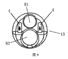
図6は、本発明の1つの実施例の可撓性シースの一部構造模式図1である。図7は、図3におけるA-Aの断面模式図1である。図8は、図3におけるA-Aの断面模式図2である。図9は、本発明の1つの実施例の可撓性シースの一部構造模式図2である。
FIG. 6 is a schematic diagram 1 of a partial structure of a flexible sheath according to an embodiment of the present invention. FIG. 7 is a schematic cross-sectional view 1 of AA in FIG. FIG. 8 is a schematic
図6~図9、図2を参照しながら説明する。前記可撓性シース1は、本体部12、シース可撓管14、及び挿入部13を有する。前記本体部12は、前記シース可撓管14の後端に接続される。前記挿入部13は、前記シース可撓管14の前端に設けられる。
This will be described with reference to FIGS. 6 to 9 and 2. The flexible sheath 1 has a
前記内視鏡差し込み部11は、前記本体部12に設けられる。前記シース可撓管14及び前記挿入部13に内視鏡可撓管を受容するための可撓管通路81が形成される。前記可撓管通路81は、前記内視鏡差し込み部11内の通路に直接的又は間接的に連通される。
The
本体部12は、内視鏡差し込み部11、挿入部13、及びシース可撓管14等を設置し、可撓性シース全体を形成するための本体である。1つの実施例において、本体部12は、少なくとも送気送水バルブ15、湾曲制御部16、及びデバイスチューブ差し込み部等の少なくとも1種を有してもよい。
The
即ち、前記可撓性シース1は、送気送水バルブ15、湾曲制御部16、ロック部(図示せず)の少なくとも1種を有する。
That is, the flexible sheath 1 has at least one of an air supply /
前記湾曲制御部16は、シース可撓管14の湾曲を制御するために用いられる。
The bending
前記ロック部は、前記内視鏡本体2及び前記可撓性シース1をロックするために用いられる。
The locking portion is used to lock the
送気送水バルブ15、湾曲制御部16、及びデバイスチューブ差し込み部17は、従来技術の内視鏡シースの送気送水バルブ、湾曲制御部、及びデバイスチューブ差し込み部を参照できる。即ち、本発明は、既知の送気送水バルブ、湾曲制御部、及びデバイスチューブ差し込み部、又は改良した送気送水バルブ、湾曲制御部、及びデバイスチューブ差し込み部を利用できる。
The air supply /
シース可撓管14は、可撓性管構造であり、内視鏡通路81に挿入した内視鏡可撓管22がシース可撓管14と共に湾曲できる。
The sheath
また、シース可撓管14が本体部12の一端に設けられ、内視鏡差し込み部11が本体部12のもう一端に設けられるため、内視鏡本体2の挿入を実現できる。
Further, since the sheath
挿入部13は、シース可撓管14の末端に設けられ、必要な操作を実施するための構造である。また、その中に画像取得密封構造23の画像取得部231を設けてもよい。また、画像取得密封構造23の一部又は全部がシース可撓管14に位置してもよい。
The
挿入部13は、シース可撓管14と一体となってもよく、一体しなくてもよい。
The
挿入部13の頭端の一部構造を最適化してもよい。例えば、頭部が胴体部より小さくようにすると、内視鏡装置を人体の腔所又は切口の通路に容易に挿入できる。
The partial structure of the head end of the
図6を参照しながら説明する。1つの実施例において、挿入部13は、支持部131及び透明部132を有する。支持部131は、その前端が透明部132に接続され、その後端がシース可撓管14に接続される。画像取得部131は、透明部132を介して前方の画面を取得できる。
This will be described with reference to FIG. In one embodiment, the
図6、図7~図9を参照しながら説明する。前記可撓性シース1は、マルチルーメンチューブ8を有する。前記マルチルーメンチューブ8は、内視鏡可撓管22を受容するための可撓管通路81を有する。前記可撓管通路81は、前記内視鏡差し込み部11内の通路に直接的又は間接的に連通される。そのため、内視鏡本体2を内視鏡差し込み部11内の通路に挿入した時に、内視鏡可撓管22を可撓管通路81に挿入できる。
This will be described with reference to FIGS. 6 and 7 to 9. The flexible sheath 1 has a
それに対応し、可撓性シース1は、内視鏡本体2をガイド及び固定するための構造、例えばレール構造を有してもよい。レール構造は、その前端が内視鏡差し込み部11に接続され、その後端がシース可撓管14及び/又はマルチルーメンチューブ8に接続される。固定構造によってマルチルーメンチューブ8と本体部12との相対的な位置を固定し、内視鏡可撓管22をシース可撓管14に容易に挿入できる。
Correspondingly, the flexible sheath 1 may have a structure for guiding and fixing the
図10は、本発明の1つの実施例の導電部と光源導線とを接触接続する模式図である。 FIG. 10 is a schematic diagram in which the conductive portion of one embodiment of the present invention and the light source conducting wire are contact-connected.
図10において、上記固定構造18を例示する。固定構造18は、その一側に導電部5を挿入するための第1溝、そのもう一側にマルチルーメンチューブ8を挿入するための第2溝を設ける。両側をそれぞれ挿入すると、導電部5とマルチルーメンチューブ8の光源導線6とを導通できる。
In FIG. 10, the fixed
その他の例において、固定構造は、例えば伝導部を有する。伝導部を利用して両側の導電部5及び光源導線6を導通できる。また、固定構造によって各部の位置を固定しなくてもよい。その場合、導電部5と光源導線6とを直接的又は間接的に接触導通してもよい。
In other examples, the fixed structure has, for example, a conduction section. The
1つの実施例において、前記光源導線6は、光源導線通路83に穿設される。
In one embodiment, the light
図7において、前記光源導線通路83が前記マルチルーメンチューブ8の外側に設けられ、具体的にマルチルーメンチューブ8の外側とシース可撓管14の管壁の内側との間の空間に設けられる。それによって、光源導線通路83と可撓管通路81を隔離できる。
In FIG. 7, the light source
図8において、前記光源導線通路83が前記マルチルーメンチューブ8の内側に設けられ、前記光源導線通路と前記可撓管通路を隔離できる。
In FIG. 8, the light
上記実施例によれば、画像取得部に対応する可撓管通路及び光源部に対応する光源導線通路は、同じ通路ではなく、管壁によって物理的に隔離される。そのため、光の干渉を阻止又は減少できる。 According to the above embodiment, the flexible tube passage corresponding to the image acquisition section and the light source lead path corresponding to the light source section are not the same passage but are physically separated by the tube wall. Therefore, the interference of light can be prevented or reduced.
図7~図9を参照しながら説明する。1つの実施例において、前記マルチルーメンチューブは、デバイスチューブ通路82をさらに有する。前記デバイスチューブ通路82は、前記可撓管通路81から隔離される。前記デバイスチューブ通路82及び前記可撓管通路81は、8の字で配置される。
This will be described with reference to FIGS. 7 to 9. In one embodiment, the multi-lumen tube further comprises a
それに対応し、前記可撓性シース1は、デバイスチューブを差し込むためのデバイスチューブ差し込み部17をさらに有する。前記デバイスチューブ通路82は、前記デバイスチューブ差し込み部17内の通路に直接的又は間接的に連通される。
Correspondingly, the flexible sheath 1 further has a device
前記8の字は、前記デバイスチューブ通路82及び前記可撓管通路81の断面がいずれも円形となり、2つの通路の円心がシース可撓管14の直径方向に沿って分布されると理解することができる。そのため、前記8の字は、8の字のような形として理解することもできる。
It is understood that the figure 8 has a circular cross section of the
光源部5は、8の字の両側、即ち、図7の8の字の左右両側に設けられる。
The
上記実施例によれば、空間を有効に利用できる。 According to the above embodiment, the space can be effectively used.
図11は、本発明の1つの実施例の可撓性シースの一部構造模式図3である。図12は、本発明の1つの実施例の可撓性シースの一部構造模式図4である。 FIG. 11 is a schematic partial structure diagram 3 of a flexible sheath according to an embodiment of the present invention. FIG. 12 is a schematic partial structure diagram 4 of a flexible sheath according to an embodiment of the present invention.
図11及び図12を参照しながら説明する。1つの実施例において、デバイスチューブ通路82等を形成せず、可撓管通路81のみを有する。その他の構造は、前記と同じである。
This will be described with reference to FIGS. 11 and 12. In one embodiment, the
図13は、本発明の1つの実施例の滅菌ジャケットの構造模式図である。 FIG. 13 is a structural schematic diagram of a sterile jacket according to an embodiment of the present invention.
図13を参照しながら説明する。滅菌ジャケット3は、接続部31、折り畳み防菌カバー32、及び圧縮ボックス33を有する。前記折り畳み防菌カバー32の一端が前記接続部31の後端に接続され、もう一端が前記圧縮ボックス33に接続される。前記圧縮ボックス33は、前記折り畳み防菌カバー32の後端に設けられる。前記折り畳み防菌カバーの少なくとも一部は、前記圧縮ボックス33に折り畳むことができる。圧縮ボックスに折り畳んだ防菌カバーのもう一端が圧縮ボックス33に接続される。前記圧縮ボックスに折り畳んだ防菌カバーを伸ばすと、前記可撓性シース1に差し込んだ内視鏡本体2の後端を隔離できる。
This will be described with reference to FIG. The sterile jacket 3 has a
上記実施例によれば、滅菌ジャケットを使用すると、患者及び操作者が接触する可能性がある表面部分がいずれも滅菌した使い捨て部分である。そのため、患者及び操作者と繰り返し使用可能な内視鏡本体とを完全に隔離できる。よって、使用上便利で安全である。 According to the above embodiment, when a sterile jacket is used, the surface portion that the patient and the operator may come into contact with is a sterile disposable portion. Therefore, the patient and the operator can be completely separated from the endoscope body that can be used repeatedly. Therefore, it is convenient and safe to use.
前記滅菌ジャケット3は、圧縮ボックスに折り畳んだ延伸可能な折り畳み防菌カバー32を有する。そのため、内視鏡本体、又は機械に接続される接続線によって細菌汚染を起こす問題を解決し、未滅菌区域と完全に隔離できる。使用する時に、前記内視鏡本体を可撓性シースの内視鏡差し込み部に沿って挿入した後、滅菌ジャケットをそのまま延伸することで、内視鏡本体及びその電源線と滅菌区域とを隔離できる。
The sterile jacket 3 has a stretchable foldable
以上をまとめると、本発明の内視鏡装置によれば、使い捨て可撓性シース、再利用可能な内視鏡本体、及び使い捨て滅菌ジャケットを利用し、下記効果を有する。関係者が使用する場合に、使い捨て可撓性シース及び滅菌ジャケットとしか接触せず、繰り返し使用可能な内視鏡本体と完全に隔離できる。そのため、細菌汚染等を避け、手術の感染リスクを低減できる。また、使用上便利で安全である。よって、本発明によれば、内視鏡本体の滅菌消毒処理を削減し、滅菌消毒処理による問題を避けることができる。また、可撓性シース及び滅菌ジャケットが使い捨て式であるため、コスト削減に役立つ。 Summarizing the above, according to the endoscope device of the present invention, a disposable flexible sheath, a reusable endoscope body, and a disposable sterile jacket are used to have the following effects. When used by interested parties, it only contacts the disposable flexible sheath and sterile jacket and can be completely isolated from the reusable endoscope body. Therefore, it is possible to avoid bacterial contamination and reduce the risk of surgical infection. It is also convenient and safe to use. Therefore, according to the present invention, it is possible to reduce the sterilization and disinfection treatment of the endoscope main body and avoid the problems caused by the sterilization and disinfection treatment. In addition, the flexible sheath and sterile jacket are disposable, which helps reduce costs.
なお、本発明によれば、光源部が可撓性シースに設けられ、内視鏡本体を内視鏡シースに差し込んだ後に光源部に電力を供給する。そのため、内視鏡本体の画像取得部及び光源部を一緒に密封する方法と比べると、内視鏡本体内の光源集成による散光、反射の問題を避けることができる。 According to the present invention, the light source portion is provided on the flexible sheath, and power is supplied to the light source portion after the endoscope main body is inserted into the endoscope sheath. Therefore, as compared with the method of sealing the image acquisition portion and the light source portion of the endoscope body together, it is possible to avoid the problems of light scattering and reflection due to the collection of light sources in the endoscope body.
本発明を説明するために上記実施例を開示したが、本発明は、それらに限定されない。当業者が上記実施例に基づいてなされた均等的な変更は、いずれも本発明に含む。 Although the above embodiments have been disclosed to illustrate the invention, the invention is not limited thereto. Any uniform modification made by one of ordinary skill in the art based on the above embodiments is included in the present invention.
1 可撓性シース
11 内視鏡差し込み部
12 本体部
13 挿入部
131 支持部
132 透明部
14 シース可撓管
15 送気送水バルブ
16 湾曲制御部
17 デバイスチューブ差し込み部
18 固定構造
2 内視鏡本体
21 内視鏡把手
22 内視鏡可撓管
23 画像取得密封構造
231 画像取得部
232 回路基板
233 密封外管
24 画像取得導線
3 滅菌ジャケット
31 接続部
32 折り畳み防菌カバー
33 圧縮ボックス
4 光源部
5 導電部
6 光源導線
7 電源線
8 マルチルーメンチューブ
81 可撓管通路
82 デバイスチューブ通路
83 光源導線通路
1
Claims (10)
前記内視鏡本体は、前記可撓性シースの内視鏡差し込み部から前記可撓性シースに差し込むことができ、
前記滅菌ジャケットは、前記内視鏡差し込み部の入口に設けられ、前記可撓性シースに差し込んだ内視鏡本体を外部から隔離し、
前記可撓性シースの前端近傍に光源部を有し、
前記内視鏡本体は、導電部を有し、その後端が前記導電部に導通される電源線に接続され、
前記内視鏡本体を前記可撓性シースに差し込んだ後、前記導電部が前記光源部の光源導線に直接的又は間接的に導通され、前記光源部に電力を供給することを特徴とする、
内視鏡装置。 Has a disposable flexible sheath, a reusable endoscope body, and a disposable sterile jacket,
The endoscope body can be inserted into the flexible sheath from the endoscope insertion portion of the flexible sheath.
The sterilization jacket is provided at the entrance of the endoscope insertion portion, and isolates the endoscope body inserted into the flexible sheath from the outside.
A light source portion is provided near the front end of the flexible sheath.
The endoscope body has a conductive portion, and its rear end is connected to a power line conducting to the conductive portion.
After the endoscope main body is inserted into the flexible sheath, the conductive portion is directly or indirectly conducted to the light source conducting wire of the light source portion to supply electric power to the light source portion.
Endoscope device.
前記導電部は、前記内視鏡把手に設けられることを特徴とする、
請求項1に記載の内視鏡装置。 The endoscope body has an endoscope handle, an endoscope flexible tube connected to the endoscope handle, and an image acquisition sealing structure provided at the front end of the endoscope flexible tube.
The conductive portion is provided on the endoscope handle.
The endoscope device according to claim 1.
前記回路基板は、前記電源線に直接的又は間接的に接続され、
前記画像取得部は、前記回路基板に接続されることを特徴とする、
請求項2に記載の内視鏡装置。 The image acquisition sealing structure has an image acquisition unit and a circuit board that are sealed together.
The circuit board is directly or indirectly connected to the power line.
The image acquisition unit is connected to the circuit board.
The endoscope device according to claim 2.
前記本体部は、前記シース可撓管の後端に接続され、
前記挿入部は、前記シース可撓管の前端に設けられ、
前記内視鏡差し込み部は、前記本体部に設けられ、
前記シース可撓管及び前記挿入部に内視鏡可撓管を受容するための可撓管通路が形成され、
前記可撓管通路は、前記内視鏡差し込み部内の通路に直接的又は間接的に連通されることを特徴とする、
請求項1~3のいずれか1項に記載の内視鏡装置。 The flexible sheath has a main body portion, a sheath flexible tube, and an insertion portion.
The main body is connected to the rear end of the sheath flexible tube.
The insertion portion is provided at the front end of the sheath flexible tube and is provided.
The endoscope insertion portion is provided in the main body portion and is provided.
A flexible tube passage for receiving the endoscope flexible tube is formed in the sheath flexible tube and the insertion portion.
The flexible tube passage is directly or indirectly communicated with the passage in the endoscope insertion portion.
The endoscope device according to any one of claims 1 to 3.
前記マルチルーメンチューブは、内視鏡可撓管を受容するための可撓管通路を有し、
前記可撓管通路は、前記内視鏡差し込み部内の通路に直接的又は間接的に連通されることを特徴とする、
請求項1~3のいずれか1項に記載の内視鏡装置。 The flexible sheath has a multi-lumen tube and
The multi-lumen tube has a flexible tube passage for receiving the endoscopic flexible tube.
The flexible tube passage is directly or indirectly communicated with the passage in the endoscope insertion portion.
The endoscope device according to any one of claims 1 to 3.
前記光源導線通路は、前記マルチルーメンチューブの中に設けられて前記可撓管通路から隔離されるか、又は前記マルチルーメンチューブの外に設けられることを特徴とする、
請求項5に記載の内視鏡装置。 The light source lead wire is bored in the light source lead wire passage, and is formed.
The light source lead passage is provided inside the multi-lumen tube and isolated from the flexible tube passage, or is provided outside the multi-lumen tube.
The endoscope device according to claim 5.
前記デバイスチューブ通路は、前記可撓管通路から隔離され、
前記デバイスチューブ通路及び前記可撓管通路は、8の字で配置されることを特徴とする、
請求項5に記載の内視鏡装置。 The multi-lumen tube further has a device tube passage and
The device tube passage is isolated from the flexible tube passage and
The device tube passage and the flexible tube passage are arranged in a figure eight.
The endoscope device according to claim 5.
前記デバイスチューブ通路は、前記デバイスチューブ差し込み部内の通路に直接的又は間接的に連通されることを特徴とする、
請求項7に記載の内視鏡装置。 The flexible sheath further comprises a device tube insertion portion for inserting the device tube.
The device tube passage is directly or indirectly communicated with the passage in the device tube insertion portion.
The endoscope device according to claim 7.
前記湾曲制御部は、シース可撓管の湾曲を制御するために用いられ、
前記ロック部は、前記内視鏡本体及び前記可撓性シースをロックするために用いられることを特徴とする、
請求項1~3のいずれか1項に記載の内視鏡装置。 The flexible sheath has at least one selected from the group consisting of an air supply / water supply valve, a bending control unit, and a lock unit.
The bending control unit is used to control the bending of the sheath flexible tube.
The locking portion is characterized in that it is used to lock the endoscope body and the flexible sheath.
The endoscope device according to any one of claims 1 to 3.
前記折り畳み防菌カバーは、その一端が前記接続部の後端に接続され、もう一端が前記圧縮ボックスに接続され、
前記圧縮ボックスは、前記折り畳み防菌カバーの後端に設けられ、
前記折り畳み防菌カバーは、前記圧縮ボックスに折り畳むことができ、それを伸ばすと前記可撓性シースに差し込んだ内視鏡本体の後端を隔離できることを特徴とする、
請求項1~3のいずれか1項に記載の内視鏡装置。
The sterile jacket has a connection, a folding antibacterial cover, and a compression box.
One end of the folding antibacterial cover is connected to the rear end of the connection portion, and the other end is connected to the compression box.
The compression box is provided at the rear end of the folding antibacterial cover.
The foldable antibacterial cover can be folded into the compression box, and when extended, the rear end of the endoscope body inserted into the flexible sheath can be isolated.
The endoscope device according to any one of claims 1 to 3.
Applications Claiming Priority (3)
| Application Number | Priority Date | Filing Date | Title |
|---|---|---|---|
| CN201910392836.3A CN110151101B (en) | 2019-05-13 | 2019-05-13 | Endoscope apparatus |
| CN201910392836.3 | 2019-05-13 | ||
| PCT/CN2019/087774 WO2020228052A1 (en) | 2019-05-13 | 2019-05-21 | Endoscopic device |
Publications (2)
| Publication Number | Publication Date |
|---|---|
| JP2022520017A true JP2022520017A (en) | 2022-03-28 |
| JP7199629B2 JP7199629B2 (en) | 2023-01-06 |
Family
ID=67634279
Family Applications (1)
| Application Number | Title | Priority Date | Filing Date |
|---|---|---|---|
| JP2021543206A Active JP7199629B2 (en) | 2019-05-13 | 2019-05-21 | endoscope device |
Country Status (7)
| Country | Link |
|---|---|
| US (1) | US20220142461A1 (en) |
| EP (1) | EP3970596B1 (en) |
| JP (1) | JP7199629B2 (en) |
| CN (1) | CN110151101B (en) |
| ES (1) | ES3037623T3 (en) |
| PL (1) | PL3970596T3 (en) |
| WO (1) | WO2020228052A1 (en) |
Families Citing this family (7)
| Publication number | Priority date | Publication date | Assignee | Title |
|---|---|---|---|---|
| CN111184496A (en) * | 2020-03-04 | 2020-05-22 | 上海安清医疗器械有限公司 | Rigid endoscope |
| ES2966350T3 (en) * | 2020-03-04 | 2024-04-22 | Anqing Medical Co Ltd | flexible endoscope |
| CN111202487A (en) * | 2020-03-04 | 2020-05-29 | 上海安清医疗器械有限公司 | flexible endoscope |
| CN114305289A (en) * | 2020-09-28 | 2022-04-12 | 微创优通医疗科技(嘉兴)有限公司 | Endoscope handle, endoscope and endoscope system |
| CN113100689A (en) * | 2021-02-09 | 2021-07-13 | 上海澳华内镜股份有限公司 | Imaging assembly three-dimensional circuit and endoscope |
| CN114947698B (en) * | 2022-06-22 | 2024-11-22 | 新光维医疗科技(苏州)股份有限公司 | Endoscope |
| CN116584881A (en) * | 2023-04-26 | 2023-08-15 | 中尚医疗仪器(深圳)有限公司 | A kind of cervical tube scope and its control system |
Citations (4)
| Publication number | Priority date | Publication date | Assignee | Title |
|---|---|---|---|---|
| JPH0767829A (en) * | 1993-09-01 | 1995-03-14 | Fuji Photo Optical Co Ltd | Mechanism for preventing contamination of endoscope |
| JP2014203064A (en) * | 2013-04-10 | 2014-10-27 | オリンパス株式会社 | Endoscope apparatus, overtube, and optical adapter |
| US20170135560A1 (en) * | 2015-11-18 | 2017-05-18 | Art Healthcare Ltd. | Sheath and hub for imaging endoscope |
| WO2018075078A1 (en) * | 2016-10-22 | 2018-04-26 | Opportunity / Discovery Llc | Disposable sheath device |
Family Cites Families (20)
| Publication number | Priority date | Publication date | Assignee | Title |
|---|---|---|---|---|
| US20020087047A1 (en) * | 1999-09-13 | 2002-07-04 | Visionscope, Inc. | Miniature endoscope system |
| EP1737335B1 (en) * | 2004-03-23 | 2013-05-15 | Boston Scientific Limited | In-vivo visualization system |
| CN101371775A (en) * | 2007-11-29 | 2009-02-25 | 上海雷硕医疗器械有限公司 | Disinfection device for endoscope |
| US20100217080A1 (en) * | 2009-02-24 | 2010-08-26 | Visionscope Technologies, Llc | Disposable Sheath for Use with an Imaging System |
| WO2012170401A2 (en) * | 2011-06-06 | 2012-12-13 | Percuvision, Llc | Sensing catheter emitting radiant energy |
| US20130096385A1 (en) * | 2011-10-14 | 2013-04-18 | Intuitive Surgical Operations, Inc. | Vision probe and catheter systems |
| US20130172673A1 (en) * | 2011-12-29 | 2013-07-04 | Cook Medical Technologies Llc | Space-optimized visualization catheter |
| US20160120395A1 (en) * | 2012-09-25 | 2016-05-05 | Tianjin Bolang Science-Technology Development Co. , Ltd. | Disposable endoscope sheath |
| US20160278614A9 (en) * | 2014-04-02 | 2016-09-29 | Visionscope Technologies Llc | Devices and methods for minimally invasive arthroscopic surgery |
| CN105286775A (en) * | 2015-10-12 | 2016-02-03 | 程细高 | Flexible transforaminal endoscope provided with telescopic sheath |
| US20170265732A1 (en) * | 2016-03-11 | 2017-09-21 | Chiyi Technology Co., Ltd. | Lighting assembly for camera module of an endoscope |
| DE102016122864B4 (en) * | 2016-11-28 | 2026-02-12 | Digital Endoscopy Gmbh | Endoscope and method for the application of a camera assembly in an endoscope |
| CN107080513B (en) * | 2017-05-17 | 2018-10-16 | 武汉佑康科技有限公司 | A kind of modularization endoscope |
| CN208725690U (en) * | 2017-09-13 | 2019-04-12 | 天津市天坤光电技术有限公司 | A kind of endoscopic system |
| GB2569177B (en) * | 2017-12-08 | 2019-12-04 | Surgerytech Aps | Endoscope system |
| CN108478171A (en) * | 2018-05-29 | 2018-09-04 | 中山市环能缪特斯医疗器械科技有限公司 | A kind of mirror sheath can free bend endoscope |
| CN111989024B (en) * | 2018-07-06 | 2023-12-15 | Hoya株式会社 | endoscope |
| US20200100654A1 (en) * | 2018-09-28 | 2020-04-02 | Wipro Limited | Minimal invasive medical device |
| CN109171611B (en) * | 2018-10-25 | 2024-07-02 | 陈勇 | Endoscope apparatus |
| CN210300918U (en) * | 2019-05-13 | 2020-04-14 | 上海英诺伟医疗器械有限公司 | Endoscope device |
-
2019
- 2019-05-13 CN CN201910392836.3A patent/CN110151101B/en active Active
- 2019-05-21 JP JP2021543206A patent/JP7199629B2/en active Active
- 2019-05-21 PL PL19928897.8T patent/PL3970596T3/en unknown
- 2019-05-21 ES ES19928897T patent/ES3037623T3/en active Active
- 2019-05-21 US US17/431,911 patent/US20220142461A1/en not_active Abandoned
- 2019-05-21 WO PCT/CN2019/087774 patent/WO2020228052A1/en not_active Ceased
- 2019-05-21 EP EP19928897.8A patent/EP3970596B1/en active Active
Patent Citations (4)
| Publication number | Priority date | Publication date | Assignee | Title |
|---|---|---|---|---|
| JPH0767829A (en) * | 1993-09-01 | 1995-03-14 | Fuji Photo Optical Co Ltd | Mechanism for preventing contamination of endoscope |
| JP2014203064A (en) * | 2013-04-10 | 2014-10-27 | オリンパス株式会社 | Endoscope apparatus, overtube, and optical adapter |
| US20170135560A1 (en) * | 2015-11-18 | 2017-05-18 | Art Healthcare Ltd. | Sheath and hub for imaging endoscope |
| WO2018075078A1 (en) * | 2016-10-22 | 2018-04-26 | Opportunity / Discovery Llc | Disposable sheath device |
Also Published As
| Publication number | Publication date |
|---|---|
| EP3970596C0 (en) | 2025-08-06 |
| EP3970596A4 (en) | 2023-06-07 |
| ES3037623T3 (en) | 2025-10-03 |
| EP3970596A1 (en) | 2022-03-23 |
| US20220142461A1 (en) | 2022-05-12 |
| PL3970596T3 (en) | 2025-10-06 |
| EP3970596B1 (en) | 2025-08-06 |
| JP7199629B2 (en) | 2023-01-06 |
| WO2020228052A1 (en) | 2020-11-19 |
| CN110151101B (en) | 2024-06-07 |
| CN110151101A (en) | 2019-08-23 |
Similar Documents
| Publication | Publication Date | Title |
|---|---|---|
| JP7199629B2 (en) | endoscope device | |
| KR102617407B1 (en) | Endoscope with variable profile tip | |
| JP5388371B2 (en) | Endoscopic device having an external rail | |
| JP7274073B2 (en) | Rigid endoscope device | |
| WO2001001847A1 (en) | Penetrating endoscope and endoscopic surgical instrument with cmos image sensor and display | |
| EP3998014B1 (en) | Soft endoscopic device | |
| CN201701191U (en) | Pipeline endoscope | |
| US20220240760A1 (en) | Single use endoscopes, cannulas, and obturators with integrated vision and illumination | |
| US8403826B1 (en) | Video endoscope for diagnostic and therapeutic usage | |
| US20210307596A1 (en) | Multi-channel system | |
| CN210300918U (en) | Endoscope device | |
| CN210749132U (en) | Rigid endoscopic device | |
| JP7370474B2 (en) | flexible endoscope | |
| JP3014213B2 (en) | Oblique endoscope | |
| JP3762508B2 (en) | Endoscope device | |
| CN211633188U (en) | Multifunctional endoscope sheath system with light path | |
| CN205338887U (en) | Flexible electronic endoscope and checkout system | |
| JP2009136450A (en) | Endoscope system | |
| JPH10192237A (en) | Endoscopic process support device |
Legal Events
| Date | Code | Title | Description |
|---|---|---|---|
| A621 | Written request for application examination |
Free format text: JAPANESE INTERMEDIATE CODE: A621 Effective date: 20210726 |
|
| A977 | Report on retrieval |
Free format text: JAPANESE INTERMEDIATE CODE: A971007 Effective date: 20220721 |
|
| A131 | Notification of reasons for refusal |
Free format text: JAPANESE INTERMEDIATE CODE: A131 Effective date: 20220725 |
|
| A521 | Request for written amendment filed |
Free format text: JAPANESE INTERMEDIATE CODE: A523 Effective date: 20220816 |
|
| TRDD | Decision of grant or rejection written | ||
| A01 | Written decision to grant a patent or to grant a registration (utility model) |
Free format text: JAPANESE INTERMEDIATE CODE: A01 Effective date: 20221111 |
|
| A711 | Notification of change in applicant |
Free format text: JAPANESE INTERMEDIATE CODE: A711 Effective date: 20221128 |
|
| A61 | First payment of annual fees (during grant procedure) |
Free format text: JAPANESE INTERMEDIATE CODE: A61 Effective date: 20221128 |
|
| A521 | Request for written amendment filed |
Free format text: JAPANESE INTERMEDIATE CODE: A821 Effective date: 20221201 |
|
| R150 | Certificate of patent or registration of utility model |
Ref document number: 7199629 Country of ref document: JP Free format text: JAPANESE INTERMEDIATE CODE: R150 |
|
| R250 | Receipt of annual fees |
Free format text: JAPANESE INTERMEDIATE CODE: R250 |