JP2022114193A - Display panel with touch sensor function and method for manufacturing display panel with touch sensor function - Google Patents
Display panel with touch sensor function and method for manufacturing display panel with touch sensor function Download PDFInfo
- Publication number
- JP2022114193A JP2022114193A JP2021010377A JP2021010377A JP2022114193A JP 2022114193 A JP2022114193 A JP 2022114193A JP 2021010377 A JP2021010377 A JP 2021010377A JP 2021010377 A JP2021010377 A JP 2021010377A JP 2022114193 A JP2022114193 A JP 2022114193A
- Authority
- JP
- Japan
- Prior art keywords
- touch sensor
- insulating layer
- opening
- electrode
- display panel
- Prior art date
- Legal status (The legal status is an assumption and is not a legal conclusion. Google has not performed a legal analysis and makes no representation as to the accuracy of the status listed.)
- Pending
Links
- 238000004519 manufacturing process Methods 0.000 title claims abstract description 29
- 238000000034 method Methods 0.000 title claims abstract description 13
- 239000000758 substrate Substances 0.000 claims description 27
- 238000001579 optical reflectometry Methods 0.000 claims 1
- 230000003071 parasitic effect Effects 0.000 abstract description 12
- 239000010410 layer Substances 0.000 description 246
- 239000010408 film Substances 0.000 description 34
- 239000011159 matrix material Substances 0.000 description 21
- 239000004973 liquid crystal related substance Substances 0.000 description 17
- 238000002834 transmittance Methods 0.000 description 17
- 239000010409 thin film Substances 0.000 description 10
- 230000005684 electric field Effects 0.000 description 9
- 238000001514 detection method Methods 0.000 description 8
- VYPSYNLAJGMNEJ-UHFFFAOYSA-N Silicium dioxide Chemical compound O=[Si]=O VYPSYNLAJGMNEJ-UHFFFAOYSA-N 0.000 description 6
- 238000010586 diagram Methods 0.000 description 6
- 230000005685 electric field effect Effects 0.000 description 6
- 229910052814 silicon oxide Inorganic materials 0.000 description 6
- 229910052581 Si3N4 Inorganic materials 0.000 description 5
- 229910004205 SiNX Inorganic materials 0.000 description 5
- 239000000463 material Substances 0.000 description 5
- HQVNEWCFYHHQES-UHFFFAOYSA-N silicon nitride Chemical compound N12[Si]34N5[Si]62N3[Si]51N64 HQVNEWCFYHHQES-UHFFFAOYSA-N 0.000 description 5
- 229910004298 SiO 2 Inorganic materials 0.000 description 4
- 239000010949 copper Substances 0.000 description 4
- 239000011521 glass Substances 0.000 description 4
- 230000004048 modification Effects 0.000 description 4
- 238000012986 modification Methods 0.000 description 4
- 230000005540 biological transmission Effects 0.000 description 3
- RYGMFSIKBFXOCR-UHFFFAOYSA-N Copper Chemical compound [Cu] RYGMFSIKBFXOCR-UHFFFAOYSA-N 0.000 description 2
- 239000003086 colorant Substances 0.000 description 2
- 238000004040 coloring Methods 0.000 description 2
- 239000000470 constituent Substances 0.000 description 2
- 229910052802 copper Inorganic materials 0.000 description 2
- 230000000593 degrading effect Effects 0.000 description 2
- 238000006073 displacement reaction Methods 0.000 description 2
- 230000000694 effects Effects 0.000 description 2
- 239000002184 metal Substances 0.000 description 2
- 229910052751 metal Inorganic materials 0.000 description 2
- 239000000203 mixture Substances 0.000 description 2
- 239000004065 semiconductor Substances 0.000 description 2
- 230000035945 sensitivity Effects 0.000 description 2
- 239000010936 titanium Substances 0.000 description 2
- RTAQQCXQSZGOHL-UHFFFAOYSA-N Titanium Chemical compound [Ti] RTAQQCXQSZGOHL-UHFFFAOYSA-N 0.000 description 1
- 230000015572 biosynthetic process Effects 0.000 description 1
- 238000005520 cutting process Methods 0.000 description 1
- AMGQUBHHOARCQH-UHFFFAOYSA-N indium;oxotin Chemical compound [In].[Sn]=O AMGQUBHHOARCQH-UHFFFAOYSA-N 0.000 description 1
- 238000009413 insulation Methods 0.000 description 1
- 230000003287 optical effect Effects 0.000 description 1
- 239000002356 single layer Substances 0.000 description 1
- 229910052719 titanium Inorganic materials 0.000 description 1
Images


Classifications
-
- G—PHYSICS
- G06—COMPUTING; CALCULATING OR COUNTING
- G06F—ELECTRIC DIGITAL DATA PROCESSING
- G06F3/00—Input arrangements for transferring data to be processed into a form capable of being handled by the computer; Output arrangements for transferring data from processing unit to output unit, e.g. interface arrangements
- G06F3/01—Input arrangements or combined input and output arrangements for interaction between user and computer
- G06F3/03—Arrangements for converting the position or the displacement of a member into a coded form
- G06F3/041—Digitisers, e.g. for touch screens or touch pads, characterised by the transducing means
- G06F3/0412—Digitisers structurally integrated in a display
-
- G—PHYSICS
- G02—OPTICS
- G02F—OPTICAL DEVICES OR ARRANGEMENTS FOR THE CONTROL OF LIGHT BY MODIFICATION OF THE OPTICAL PROPERTIES OF THE MEDIA OF THE ELEMENTS INVOLVED THEREIN; NON-LINEAR OPTICS; FREQUENCY-CHANGING OF LIGHT; OPTICAL LOGIC ELEMENTS; OPTICAL ANALOGUE/DIGITAL CONVERTERS
- G02F1/00—Devices or arrangements for the control of the intensity, colour, phase, polarisation or direction of light arriving from an independent light source, e.g. switching, gating or modulating; Non-linear optics
- G02F1/01—Devices or arrangements for the control of the intensity, colour, phase, polarisation or direction of light arriving from an independent light source, e.g. switching, gating or modulating; Non-linear optics for the control of the intensity, phase, polarisation or colour
- G02F1/13—Devices or arrangements for the control of the intensity, colour, phase, polarisation or direction of light arriving from an independent light source, e.g. switching, gating or modulating; Non-linear optics for the control of the intensity, phase, polarisation or colour based on liquid crystals, e.g. single liquid crystal display cells
- G02F1/133—Constructional arrangements; Operation of liquid crystal cells; Circuit arrangements
- G02F1/1333—Constructional arrangements; Manufacturing methods
- G02F1/13338—Input devices, e.g. touch panels
-
- G—PHYSICS
- G02—OPTICS
- G02F—OPTICAL DEVICES OR ARRANGEMENTS FOR THE CONTROL OF LIGHT BY MODIFICATION OF THE OPTICAL PROPERTIES OF THE MEDIA OF THE ELEMENTS INVOLVED THEREIN; NON-LINEAR OPTICS; FREQUENCY-CHANGING OF LIGHT; OPTICAL LOGIC ELEMENTS; OPTICAL ANALOGUE/DIGITAL CONVERTERS
- G02F1/00—Devices or arrangements for the control of the intensity, colour, phase, polarisation or direction of light arriving from an independent light source, e.g. switching, gating or modulating; Non-linear optics
- G02F1/01—Devices or arrangements for the control of the intensity, colour, phase, polarisation or direction of light arriving from an independent light source, e.g. switching, gating or modulating; Non-linear optics for the control of the intensity, phase, polarisation or colour
- G02F1/13—Devices or arrangements for the control of the intensity, colour, phase, polarisation or direction of light arriving from an independent light source, e.g. switching, gating or modulating; Non-linear optics for the control of the intensity, phase, polarisation or colour based on liquid crystals, e.g. single liquid crystal display cells
- G02F1/133—Constructional arrangements; Operation of liquid crystal cells; Circuit arrangements
- G02F1/1333—Constructional arrangements; Manufacturing methods
- G02F1/1343—Electrodes
- G02F1/13439—Electrodes characterised by their electrical, optical, physical properties; materials therefor; method of making
-
- G—PHYSICS
- G02—OPTICS
- G02F—OPTICAL DEVICES OR ARRANGEMENTS FOR THE CONTROL OF LIGHT BY MODIFICATION OF THE OPTICAL PROPERTIES OF THE MEDIA OF THE ELEMENTS INVOLVED THEREIN; NON-LINEAR OPTICS; FREQUENCY-CHANGING OF LIGHT; OPTICAL LOGIC ELEMENTS; OPTICAL ANALOGUE/DIGITAL CONVERTERS
- G02F1/00—Devices or arrangements for the control of the intensity, colour, phase, polarisation or direction of light arriving from an independent light source, e.g. switching, gating or modulating; Non-linear optics
- G02F1/01—Devices or arrangements for the control of the intensity, colour, phase, polarisation or direction of light arriving from an independent light source, e.g. switching, gating or modulating; Non-linear optics for the control of the intensity, phase, polarisation or colour
- G02F1/13—Devices or arrangements for the control of the intensity, colour, phase, polarisation or direction of light arriving from an independent light source, e.g. switching, gating or modulating; Non-linear optics for the control of the intensity, phase, polarisation or colour based on liquid crystals, e.g. single liquid crystal display cells
- G02F1/133—Constructional arrangements; Operation of liquid crystal cells; Circuit arrangements
- G02F1/136—Liquid crystal cells structurally associated with a semi-conducting layer or substrate, e.g. cells forming part of an integrated circuit
- G02F1/1362—Active matrix addressed cells
- G02F1/136286—Wiring, e.g. gate line, drain line
- G02F1/136295—Materials; Compositions; Manufacture processes
-
- G—PHYSICS
- G06—COMPUTING; CALCULATING OR COUNTING
- G06F—ELECTRIC DIGITAL DATA PROCESSING
- G06F3/00—Input arrangements for transferring data to be processed into a form capable of being handled by the computer; Output arrangements for transferring data from processing unit to output unit, e.g. interface arrangements
- G06F3/01—Input arrangements or combined input and output arrangements for interaction between user and computer
- G06F3/03—Arrangements for converting the position or the displacement of a member into a coded form
- G06F3/041—Digitisers, e.g. for touch screens or touch pads, characterised by the transducing means
- G06F3/0416—Control or interface arrangements specially adapted for digitisers
- G06F3/04164—Connections between sensors and controllers, e.g. routing lines between electrodes and connection pads
-
- G—PHYSICS
- G06—COMPUTING; CALCULATING OR COUNTING
- G06F—ELECTRIC DIGITAL DATA PROCESSING
- G06F3/00—Input arrangements for transferring data to be processed into a form capable of being handled by the computer; Output arrangements for transferring data from processing unit to output unit, e.g. interface arrangements
- G06F3/01—Input arrangements or combined input and output arrangements for interaction between user and computer
- G06F3/03—Arrangements for converting the position or the displacement of a member into a coded form
- G06F3/041—Digitisers, e.g. for touch screens or touch pads, characterised by the transducing means
- G06F3/044—Digitisers, e.g. for touch screens or touch pads, characterised by the transducing means by capacitive means
- G06F3/0443—Digitisers, e.g. for touch screens or touch pads, characterised by the transducing means by capacitive means using a single layer of sensing electrodes
-
- G—PHYSICS
- G06—COMPUTING; CALCULATING OR COUNTING
- G06F—ELECTRIC DIGITAL DATA PROCESSING
- G06F3/00—Input arrangements for transferring data to be processed into a form capable of being handled by the computer; Output arrangements for transferring data from processing unit to output unit, e.g. interface arrangements
- G06F3/01—Input arrangements or combined input and output arrangements for interaction between user and computer
- G06F3/03—Arrangements for converting the position or the displacement of a member into a coded form
- G06F3/041—Digitisers, e.g. for touch screens or touch pads, characterised by the transducing means
- G06F3/044—Digitisers, e.g. for touch screens or touch pads, characterised by the transducing means by capacitive means
- G06F3/0445—Digitisers, e.g. for touch screens or touch pads, characterised by the transducing means by capacitive means using two or more layers of sensing electrodes, e.g. using two layers of electrodes separated by a dielectric layer
-
- G—PHYSICS
- G06—COMPUTING; CALCULATING OR COUNTING
- G06F—ELECTRIC DIGITAL DATA PROCESSING
- G06F3/00—Input arrangements for transferring data to be processed into a form capable of being handled by the computer; Output arrangements for transferring data from processing unit to output unit, e.g. interface arrangements
- G06F3/01—Input arrangements or combined input and output arrangements for interaction between user and computer
- G06F3/03—Arrangements for converting the position or the displacement of a member into a coded form
- G06F3/041—Digitisers, e.g. for touch screens or touch pads, characterised by the transducing means
- G06F3/0416—Control or interface arrangements specially adapted for digitisers
- G06F3/0418—Control or interface arrangements specially adapted for digitisers for error correction or compensation, e.g. based on parallax, calibration or alignment
Landscapes
- Engineering & Computer Science (AREA)
- Physics & Mathematics (AREA)
- General Engineering & Computer Science (AREA)
- Theoretical Computer Science (AREA)
- General Physics & Mathematics (AREA)
- Nonlinear Science (AREA)
- Human Computer Interaction (AREA)
- Crystallography & Structural Chemistry (AREA)
- Chemical & Material Sciences (AREA)
- Mathematical Physics (AREA)
- Optics & Photonics (AREA)
- Manufacturing & Machinery (AREA)
- Microelectronics & Electronic Packaging (AREA)
- Liquid Crystal (AREA)
- Computer Networks & Wireless Communication (AREA)
- Devices For Indicating Variable Information By Combining Individual Elements (AREA)
- Position Input By Displaying (AREA)
Abstract
Description
本開示は、タッチセンサ機能付き表示パネル及びタッチセンサ機能付き表示パネルの製造方法に関する。 The present disclosure relates to a display panel with a touch sensor function and a manufacturing method of the display panel with a touch sensor function.
従来、フルインセル型のタッチセンサ機能付き表示パネル及びタッチセンサ機能付き表示パネルの製造方法が知られている。このようなタッチセンサ機能付き表示パネルの製造方法は、例えば、特許文献1に開示されている。
Conventionally, a full-in-cell type display panel with a touch sensor function and a method of manufacturing a display panel with a touch sensor function are known. A method for manufacturing such a display panel with a touch sensor function is disclosed in
上記特許文献1のタッチセンサ機能付き表示パネルでは、液晶層側から順に、画素電極、第1の絶縁膜、センサ電極線、第2の絶縁膜、共通電極、第3の絶縁膜、及び、データ信号線が形成されている。そして、画素電極には、複数のスリットが設けられており、表示パネルは、上層の画素電極と下層の共通電極との間で横電界を生じさせることにより液晶を駆動させるように構成されている。これにより、共通電極よりも下層に配置されたデータ信号線からのノイズは、共通電極によって電界遮蔽され、データ信号線からのノイズが画素電極に到達するのが防止される。
In the display panel with a touch sensor function of
また、上記特許文献1の表示パネルでは、センサ電極線と共通電極とは、第2絶縁膜に形成されたスルーホールを介して接続されている。これにより、センサ電極線と共通電極との距離を確保することができるので、センサ電極線と共通電極との寄生容量を小さくすることができる。また、第1の絶縁膜は、画素電極とセンサ電極線とを絶縁するために、センサ電極線を覆うように形成されている。このため、画素電極と共通電極との間には、少なくとも第1の絶縁膜及び第2の絶縁膜が配置される。
In addition, in the display panel of
上記特許文献1に記載のタッチセンサ機能付き表示パネルでは、データ信号線(データ線)からのノイズが画素電極に到達することを防止すること、及び、センサ電極線と共通電極との寄生容量を小さくすることが可能である一方、画素電極と共通電極との間には、第1の絶縁膜及び第2の絶縁膜が配置される。このため、画素電極と共通電極との距離が大きくなり、液晶に対する強い電界効果が得られず、表示パネル(液晶層)の光透過率が低下するという問題点がある。
In the display panel with a touch sensor function described in
そこで、本開示は、上記のような課題を解決するためになされたものであり、データ線からのノイズが画素電極に到達することを防止し、かつ、センサ電極線(タッチセンサ線)と共通電極との寄生容量を小さくしながら、表示パネルの光透過率を向上させることが可能なタッチセンサ機能付き表示パネル及びタッチセンサ機能付き表示パネルの製造方法を提供することを目的とする。 Therefore, the present disclosure has been made to solve the above-described problems, and prevents noise from data lines from reaching pixel electrodes, and provides a sensor electrode line (touch sensor line) common to the sensor electrode line (touch sensor line). An object of the present invention is to provide a display panel with a touch sensor function and a method for manufacturing the display panel with a touch sensor function, which can improve the light transmittance of the display panel while reducing the parasitic capacitance with electrodes.
上記課題を解決するために、本開示の第1の態様に係るタッチセンサ機能付き表示パネルは、データ線と、前記データ線よりも上層に形成された共通電極と、前記共通電極の少なくとも一部を覆う第1絶縁層と、前記第1絶縁層の上層及び前記第1絶縁層に設けられた第1開口に形成されたタッチセンサ線であって、当該第1開口を介して、前記共通電極に接続されているタッチセンサ線と、前記タッチセンサ線の少なくとも一部を覆う第2絶縁層と、前記第2絶縁層の上層に形成された画素電極と、を備え、前記第1絶縁層には、前記共通電極と前記画素電極との間に第2開口が形成されており、前記第2開口の内部には、前記第2絶縁層が配置されており、前記第2絶縁層には、前記第2開口の上方の部分に下方に窪む凹部が形成されており、前記画素電極の少なくとも一部は、前記第2絶縁層の前記凹部内に配置されている。 In order to solve the above problems, a display panel with a touch sensor function according to a first aspect of the present disclosure includes data lines, a common electrode formed in a layer above the data lines, and at least part of the common electrodes. and a touch sensor line formed in a first opening provided in an upper layer of the first insulating layer and the first insulating layer, wherein the common electrode is formed through the first opening. a second insulating layer covering at least a portion of the touch sensor line; and a pixel electrode formed on the second insulating layer. a second opening is formed between the common electrode and the pixel electrode; the second insulating layer is disposed inside the second opening; and the second insulating layer includes: A recess recessed downward is formed in a portion above the second opening, and at least part of the pixel electrode is arranged in the recess of the second insulating layer.
第2の態様に係るタッチセンサ機能付き表示パネルの製造方法は、基板上に、データ線を形成する工程と、前記データ線よりも上層に、共通電極を形成する工程と、前記共通電極の少なくとも一部を覆うように、第1絶縁層を形成する工程と、前記第1絶縁層に、第1開口及び第2開口を形成する工程と、前記第1開口を介して、前記タッチセンサ線と前記共通電極とを接続させるように、前記第1絶縁層の上層及び前記第1絶縁層に設けられた前記第1開口に、タッチセンサ線を形成する工程と、前記タッチセンサ線の少なくとも一部を覆うように第2絶縁層を形成するとともに、前記第2開口の上方の部分に凹部が形成されるように、前記第2開口に当該第2絶縁層を形成する工程と、前記第2絶縁層の上層に画素電極を形成する工程であって、前記第2絶縁層の前記凹部に前記画素電極の少なくとも一部が配置されるように、画素電極を形成する工程と、をさらに備える。 A method for manufacturing a display panel with a touch sensor function according to a second aspect includes the steps of: forming data lines on a substrate; forming common electrodes in a layer above the data lines; forming a first insulating layer to partially cover; forming a first opening and a second opening in the first insulating layer; and forming the touch sensor line through the first opening. forming a touch sensor line in the first opening provided in the upper layer of the first insulating layer and the first insulating layer so as to be connected to the common electrode; and at least part of the touch sensor line. forming a second insulating layer to cover the second insulating layer and forming the second insulating layer in the second opening such that a recess is formed in a portion above the second opening; forming a pixel electrode in an upper layer of the layer, the pixel electrode being formed such that at least a portion of the pixel electrode is disposed in the recess of the second insulating layer.
上記構成によれば、データ線からのノイズが画素電極に到達することを防止し、かつ、タッチセンサ線と共通電極との寄生容量を小さくしながら、表示パネルの光透過率を向上させることが可能になる。 According to the above configuration, the light transmittance of the display panel can be improved while preventing noise from the data line from reaching the pixel electrode and reducing the parasitic capacitance between the touch sensor line and the common electrode. be possible.
以下、図面を参照し、本開示の実施形態を詳しく説明する。図中同一または相当部分には同一符号を付してその説明は繰り返さない。なお、説明を分かりやすくするために、以下で参照する図面においては、構成が簡略化または模式化して示されたり、一部の構成部材が省略されたりしている。また、各図に示された構成部材間の寸法比は、必ずしも実際の寸法比を示すものではない。 Hereinafter, embodiments of the present disclosure will be described in detail with reference to the drawings. The same or corresponding parts in the drawings are denoted by the same reference numerals, and the description thereof will not be repeated. In addition, in order to make the description easier to understand, in the drawings referred to below, the configuration is shown in a simplified or schematic form, or some constituent members are omitted. Also, the dimensional ratios between the constituent members shown in each drawing do not necessarily indicate the actual dimensional ratios.
[第1実施形態]
第1実施形態による表示装置100の構成について説明する。図1は、第1実施形態に係る表示装置100の構成を示すブロック図である。図1に示すように、表示装置100は、タッチセンサ機能付き表示パネル1(以下、「表示パネル1」という)と、コントローラ2とを備える。
[First embodiment]
The configuration of the
表示パネル1は、映像または画像を表示する機能、及び、指示体からのタッチ及びタッチ位置を検出する機能を有する。また、表示パネル1は、フルインセル型のタッチパネルである。コントローラ2は、表示パネル1から取得したタッチ位置に基づいて、表示装置100における各制御処理を実行する。
The
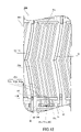
図2は、表示パネル1の一部を模式的に示した平面図である。また、図3は、表示パネル1の第1絶縁層11dの構成を示す平面図である。また、図4は、図2の1000-1000線に沿った断面図である。図4に示すように、表示パネル1は、アクティブマトリクス基板10と、対向基板20と、アクティブマトリクス基板10と対向基板20とに挟持された液晶層30とを有する。対向基板20の表面(以下、タッチ面)側からユーザが画像を視認する。また、表示パネル1は、タッチ面において、例えば、指等(指示体)によるタッチ操作を受け付ける。
FIG. 2 is a plan view schematically showing part of the
図4に示すように、対向基板20には、タッチ面側から順に、ガラス基板21、ブラックマトリクス22、カラーフィルタ23、透光性固着層24、及び、配向膜25が配置されている。ブラックマトリクス22には、開口22aが設けられており、当該開口22aは、液晶層30側からの光をタッチ面側に透過させる光透過部として機能する。
As shown in FIG. 4, on the
(アクティブマトリクス基板の構成)
図4に示すように、アクティブマトリクス基板10には、液晶層30とは反対側から順に、ガラス基板10a、ゲート線18(図5参照)、ゲート絶縁層11a、データ線12及びドレイン電極17、データ線絶縁層11b、有機絶縁層11c、共通電極13、第1絶縁層11d、タッチセンサ線14及び接続電極15、第2絶縁層11e、画素電極16、及び、配向膜19が設けられている。なお、以下の説明において、「上」とは、図4のZ方向を意味するものとし、アクティブマトリクス基板10において、液晶層30側を意味するものとする。また「下」とは、図4のZ方向と反対側を意味するものとし、アクティブマトリクス基板10において、ガラス基板10a側を意味するものとする。
(Structure of active matrix substrate)
As shown in FIG. 4, the
画素電極16と共通電極13との間に電界を生じさせることにより、液晶層30に含まれる液晶分子が駆動する。画素電極16には、複数のスリット16aが設けられおり、液晶分子は横電界駆動方式により駆動する。共通電極13は、複数の画素電極16に共通して設けられている。また、共通電極13は、画素電極16の対向電極として機能するのみならず、共通電極13は、タッチセンサ線14(下部電極層14a)に接続されており、タッチセンサ電極としても機能する。なお、画素電極16に設けられるスリット16aは、一つの画素電極16に対して必ずしも複数設けられていなくてもよく、少なくとも1つのスリット16aが設けられていればよい。
By generating an electric field between the
図5は、アクティブマトリクス基板10の構成を模式的に示す平面図である。アクティブマトリクス基板10には、ゲートドライバ41及びソースドライバ42が設けられている。複数のゲート線18と複数のデータ線12とは、平面視において、互いに交差しており格子状に形成されている。また、図2に示すように、アクティブマトリクス基板10には、複数のゲート線18と複数のデータ線12とに接続された薄膜トランジスタ50が設けられている。
FIG. 5 is a plan view schematically showing the configuration of the
図6は、薄膜トランジスタ50とゲート線18及びデータ線12との接続を説明するための模式的な回路図である。図6に示すように、薄膜トランジスタ50のゲート電極が、ゲート線18に接続されており、薄膜トランジスタ50のソース電極がデータ線12に接続されている。また、薄膜トランジスタ50のドレイン電極17は、画素電極16に接続されている。
FIG. 6 is a schematic circuit diagram for explaining connections between the
図5に示すように、複数のゲート線18は、複数の画素電極16に接続された薄膜トランジスタ50の各々とゲートドライバ41とを接続する。また、複数のデータ線12は、複数の画素電極16に接続された薄膜トランジスタ50の各々とソースドライバ42とを接続する。また、ゲートドライバ41及びソースドライバ42は、それぞれ、複数の画素電極16が配置される表示領域E1よりも外側の額縁領域に配置される。ゲートドライバ41及びソースドライバ42は、例えば、集積回路から構成される。ゲートドライバ41は、複数のゲート線18の各々に順次、ゲート信号(走査信号)を供給する。具体的には、ゲートドライバ41は、コントローラ2からの水平同期信号に基づいて、複数のゲート線18に順次電圧を印加する(走査する)。ソースドライバ42は、複数のデータ線12の各々に、データ信号(ソース信号)を供給する。
As shown in FIG. 5 , the plurality of
図7は、図5とは異なる層におけるアクティブマトリクス基板10の構成を模式的に示す平面図である。アクティブマトリクス基板10は、タッチ検出ドライバ43を含む。タッチ検出ドライバ43は、例えば、集積回路から構成される。タッチ検出ドライバ43と各共通電極13とは、それぞれ、タッチセンサ線14を介して接続されている。タッチ検出ドライバ43は、各共通電極13に駆動信号を送信するとともに、各共通電極13からの信号を受信する。そして、タッチ検出ドライバ43は、受信した信号に基づいて指示体(例えば、指)によるタッチ位置を検出する。
FIG. 7 is a plan view schematically showing the configuration of the
図8は、図7における領域A1の拡大図である。図8に示すように、タッチセンサ線14は、共通電極13と複数の箇所(開口64)において接続されている。また、共通電極13よりも上層で、平面視においてタッチセンサ線14と異なる位置にダミー配線14cが設けられている。ダミー配線14cは、タッチセンサ線14と平行に延びており、タッチ検出ドライバ43とは直接接続されていない。なお、「ダミー配線14cは、タッチ検出ドライバ43とは直接接続されていない」状態には、例えば、ダミー配線14cが、共通電極13とタッチセンサ線14とを介して、タッチ検出ドライバ43と電気的に接続されている状態が含まれる。また、タッチセンサ線14は、複数の共通電極13に亘って配置されている一方、ダミー配線14cは、単一の共通電極13上に配置されている。ダミー配線14c及びタッチセンサ線14となる複数の線は、同一の製造工程にて形成される。そして、複数の線のうちのタッチセンサ線14として機能させる線以外の線が、複数の共通電極13の境界で切断されることにより、ダミー配線14cが形成される。これにより、共通電極13及び当該共通電極13に接続された複数のダミー配線14cは、他の共通電極13のダミー配線14cから電気的に独立させることができる。
FIG. 8 is an enlarged view of area A1 in FIG. As shown in FIG. 8, the
そして、ダミー配線14cは、例えば、共通電極13のITOよりも抵抗値が小さいCu(銅)により構成されている。そして、ダミー配線14cと共通電極13とは、開口64を介して接続されている。この結果、ダミー配線14c及び共通電極13を1つのセグメントとして見た場合に、ダミー配線14cが設けられていない場合に比べて当該セグメントの抵抗値を小さくすることが可能となる。また、図8に示すように、複数のダミー配線14cは、共通電極13上で、タッチセンサ線14と並んで、等間隔で平行に配置されている。これによると、平面視における各共通電極13の形状の差異を低減することができる。詳細には、いずれの共通電極13においても、同様に、タッチセンサ線14と複数のダミー配線14cとが並列して配置されているので、タッチセンサ線14とダミー配線14cとの間の光透過部分の形状、及び複数のダミー配線14c同士の間の光透過部分の形状が、互いに等しくなる。この結果、各ライン毎(RGB画素)の光学的差異(透過率変化)を無くすことができ、色度ズレを防止することができる。この効果は、特に平面斜め方向から共通電極13を見た場合に顕著となる。
The
(アクティブマトリクス基板における各層の構成)
図4に示すように、ゲート絶縁層11aは、ガラス基板10aの上層に形成されている。ゲート絶縁層11aは、ゲート線18(図5参照)を覆うように形成されている。ゲート絶縁層11aは、無機絶縁膜からなり、例えば、窒化珪素(SiNx)または酸化珪素(SiO2)からなる。また、ゲート線18は、金属膜からなる。
(Structure of Each Layer in Active Matrix Substrate)
As shown in FIG. 4, the
データ線12及びドレイン電極17は、ゲート絶縁層11aの上に形成されており、金属膜からなる。
The
データ線絶縁層11bは、データ線12及びドレイン電極17を覆うように形成されている。データ線絶縁層11bは、無機絶縁膜からなり、例えば、窒化珪素(SiNx)または酸化珪素(SiO2)からなる。データ線絶縁層11bには、ドレイン電極17の上方において、タッチセンサ線14と同一の層に形成された接続電極15の一部が配置される開口61aが設けられている。開口61aは、平面視で、ブラックマトリクス22の開口22aとはオーバラップしない位置に形成されている。
The data line insulating
有機絶縁層11cは、データ線絶縁層11bの上に形成されている。また、有機絶縁層11cの膜厚は、1μm以上4μm以下が望ましい。ここで、有機絶縁層11cの膜厚が厚い程、絶縁性能が向上し、かつデータ線12と共通電極13と間の寄生容量を小さくでき、タッチパネルとしての感度を向上させることが可能である。この点から、有機絶縁層11cの膜厚は、1μm以上が望ましい。但し、厚くするデメリットとして、パターン加工が難しくなるため、有機絶縁層11cの膜厚は、4μm以下が望ましい。また、有機絶縁層11cには、ドレイン電極17の上方において、第1絶縁層11dの一部が配置される開口62が設けられている。
The organic insulating
共通電極13は、有機絶縁層11cの上に形成されている。共通電極13は、例えば、透明導電膜(例えば、ITO:Indium-tin-oxide)からなる。共通電極13は、データ線12よりも上層で、かつ、画素電極16よりも下層に形成されている。また、共通電極13には、第1絶縁層11dが配置される開口13aが設けられている。開口13aは、図2に示すように、平面視で、開口61a及び61bと、開口62と、開口65とオーバラップする位置に形成されている。
A
図4に示すように、第1絶縁層11dは、共通電極13の少なくとも一部を覆うとともに、開口13a内及び開口62に形成されている。第1絶縁層11dは、無機絶縁膜からなり、例えば、窒化珪素(SiNx)または酸化珪素(SiO2)からなる。図9は、図4と平面視で異なる位置におけるアクティブマトリクス基板10の断面図である。図9に示すように、第1絶縁層11dは、共通電極13と当該共通電極13に接続されないタッチセンサ線14との絶縁を行う機能を有する。また、第1絶縁層11dの膜厚は、150nm以上500nm以下が望ましい。ここで、第1絶縁層11dの膜厚が厚い程、絶縁性能が向上し、かつ共通電極13と当該共通電極13に接続されないタッチセンサ線14と間の寄生容量を小さくでき、タッチパネルとしての感度を向上させることが可能である。この点から、第1絶縁層11dの膜厚は、150nm以上が望ましい。但し、厚くするデメリットとして、パターン加工が難しくなるため、第1絶縁層11dの膜厚は、500nm以下が望ましい。また、第1実施形態では、第1絶縁層11dには、共通電極13と画素電極16との間に、第2絶縁層11eが配置された開口63が形成されている。
As shown in FIG. 4 , the first insulating
また、第1絶縁層11dには、ドレイン電極17の上方に開口61bが形成されている。開口61bは、データ線絶縁層11bの開口61aと上下方向に連続している。また、図4に示すように、第1絶縁層11dには、共通電極13の上方において、当該共通電極13に接続されるタッチセンサ線14の一部が配置される開口64が形成されている。また、図3に示すように、開口61bと、開口63と、開口64とは、平面視において、互いに別個に離れて形成されている。また、図4に示すように、開口63は、平面視において、共通電極13が配置されていない部分には設けられていない。これにより、共通電極13が配置されていない部分において、データ線12と画素電極16との距離が小さくなり、データ線12と画素電極16との寄生容量が大きくなるのを防止することができる。
An
図4に示すように、タッチセンサ線14は、第1絶縁層11dの一部の上層と、第1絶縁層11dの開口64とに形成されている。そして、タッチセンサ線14は、開口64を介して、共通電極13に接続されている。また、タッチセンサ線14は、平面視において、複数の共通電極13のうちの一つの共通電極13(図7参照)に接続されており、他の共通電極13には接続されていない。
As shown in FIG. 4, the
ここで、表示パネル1の厚み方向(Z方向)に直交する方向で、かつ、タッチセンサ線14が延びる方向(Y方向)と直交する方向である幅方向(X方向)において、タッチセンサ線14の長さ(幅)W1は、第1絶縁層11dの長さ(幅)W2以下である。図4の例では、幅W1は、幅W2よりも小さく、第1絶縁層11dのうちのタッチセンサ線14から開口63までの長さ(幅)W3は、例えば、幅W1の9分の4の寸法よりも大きい。この構成によれば、第1絶縁層11d上にタッチセンサ線14を形成する際に、第1絶縁層11dの幅W2が大きい分、タッチセンサ線14のずれを吸収することができる。すなわち、タッチセンサ線14を容易にアライメントすることができる。また、第1実施形態では、開口63のX方向の幅W4は、画素電極16の第1部分16bの幅W5よりも大きい。
Here, in the width direction (X direction), which is the direction orthogonal to the thickness direction (Z direction) of the
また、タッチセンサ線14は、データ線12と平行に形成されており、データ線12の幅W6は、タッチセンサ線14の幅W1以下である。図4の例では、幅W6は、幅W1よりも小さい。この構成によれば、データ線12の幅W6が小さいので、タッチセンサ線14とデータ線12との間で、多重反射が生じにくくなる。この結果、不要な光透過が減少するので、表示パネル1のコントラストを向上させ、色ムラの発生を抑制することができる。
Further, the
また、タッチセンサ線14は、例えば、下部電極層14aと上部電極層14bとを含む。下部電極層14aと上部電極層14bとは、積層されている。下部電極層14aは、開口64に配置されている。下部電極層14aは、上部電極層14bよりも低い光反射率を有する。例えば、下部電極層14aは、チタン(Ti)を含む。上部電極層14bは、例えば、銅(Cu)を含む。この構成によれば、下部電極層14aにおける光反射を小さくすることができるので、表示パネル1の下方から入射される光(バックライト)がデータ線12とタッチセンサ線14との間での多重反射するのを抑止することができる。この結果、表示パネル1を上方斜めから見た際の不要な色付き(混色)を防止することが可能となる。これにより、混色防止に必要なブラックマトリクス22の寸法を小さくすることが可能になり、表示品位を低下することなく、表示パネル1の光透過率をさらに向上させることができる。
Also, the
接続電極15は、ドレイン電極17と画素電極16とを電気的に接続させる機能を有する。接続電極15は、第1絶縁層11dの一部の上層と、第1絶縁層11dに設けられた開口61b及びデータ線絶縁層11bの開口61aに形成されている。そして、接続電極15は、開口61a及び61bを介して、ドレイン電極17に接続されている。また、接続電極15は、例えば、下部電極層15aと上部電極層15bとを含む。下部電極層15aと上部電極層15bとは、積層されている。下部電極層15aは、タッチセンサ線14の下部電極層14aと同一の層に形成されており、同一の材料からなる。上部電極層15bは、タッチセンサ線14の上部電極層14bと同一の層に形成されており、同一の材料からなる。
The
第2絶縁層11eは、タッチセンサ線14の少なくとも一部及び接続電極15の少なくとも一部を覆うように形成されている。第2絶縁層11eは、無機絶縁膜からなり、例えば、窒化珪素(SiNx)または酸化珪素(SiO2)からなる。また、第2絶縁層11eの膜厚は、150nm以上500nm以下が望ましい。ここで、第2絶縁層11eの膜厚が厚い程、画素電極16とタッチセンサ線14との間の絶縁性能を向上させることが可能である。この点から、第2絶縁層11eの膜厚は、150nm以上が望ましい。但し、厚くするデメリットとして、パターン加工が難しくなるため、第2絶縁層11eの膜厚は、500nm以下が望ましい。また、第1絶縁層11d及び第2絶縁層11eの膜厚は、それぞれ独立して調整可能であるため、タッチパネル性能とパネル透過率設計を両立させることが容易となる。そして、第1絶縁層11d及び第2絶縁層11eを形成するためには、特殊なプロセスを使用する必要がないので、表示パネル1の歩留まりを向上させることができる。
The second insulating
また、第2絶縁層11eの一部は、第1絶縁層11dの開口63に形成され、共通電極13と接触している。そして、第2絶縁層11eには、開口63の上方の部分63aに下方に窪む凹部70が形成されている。これにより、凹部70の底面から共通電極13の上面までの距離D1は、第2絶縁層11eの部分63aとは異なる部分63bにおける第2絶縁層11eの上面から共通電極13の上面までの距離D2よりも小さい。また、第2絶縁層11eには、接続電極15の上方に、画素電極16の第2部分16cが配置される開口65が形成されている。
A portion of the second insulating
画素電極16は、第2絶縁層11eの上層に形成されている。これにより、データ線12と画素電極16との間に共通電極13が配置されるので、データ線12からのノイズは、共通電極13によって遮蔽される。この結果、データ線12からのノイズが画素電極16に到達することを防止することができる。そして、画素電極16にノイズが到達するのを防止することができるので、画素電極16の面積を大きくすることが可能となる。これにより、表示パネル1の光透過率を向上させることができる。また、タッチセンサ線14と共通電極13との間に第1絶縁層11dが配置されるため、タッチセンサ線14と共通電極13との間の寄生容量を小さくすることができる。また、画素電極16は、例えば、透明導電膜(例えば、ITO)からなる。
The
また、画素電極16の少なくとも一部(第1部分16b)は、第2絶縁層11eの凹部70に配置されている。これにより、画素電極16の第1部分16bと共通電極13との距離は、上記の距離D2よりも小さいD1となる。さらに、画素電極16に設けられた複数のスリット16aの全てが第2絶縁層11eの凹部70に配置されている。この構成によれば、画素電極16の第1部分16bと共通電極13との距離D1が小さい分、画素電極16の第1部分16bと共通電極13との間でスリット16aを介して生じる電界効果を強くすることが可能となる。この結果、表示パネル1の光透過率を向上させることができる。なお、画素電極16に設けられた複数のスリット16aは、全ての領域が第2絶縁層11eの凹部70に配置されていることがより好ましいが、表示に実質的に寄与しない領域、例えば、スリット16aとブラックマトリクス22とが平面視で重なる領域においては、必ずしもスリット16aが第2絶縁層11eの凹部70に配置されていなくても良い。
At least part of the pixel electrode 16 (the
画素電極16の第2部分16cは、接続電極15を介して、薄膜トランジスタ50のドレイン電極17に接続されている。また、第2部分16cの一部は、第2絶縁層11eの開口65に配置されており、接続電極15の上部電極層15bに接触している。この構成によれば、ドレイン電極17と画素電極16とを接続するための接続電極15を、タッチセンサ線14を形成する工程(後述するステップS11及びS12)に併せて形成することができる。この結果、薄膜トランジスタ50と画素電極16とを接続するための工程数を削減することができる。
A
(タッチセンサ機能付き表示パネルの製造方法)
次に、図10を参照して、第1実施形態による表示パネル1の製造方法について説明する。図10は、表示パネル1の各製造工程のフローチャートを示している。
(Manufacturing method of display panel with touch sensor function)
Next, a method for manufacturing the
ステップS1において、ガラス基板10a上に、ゲート線18が形成される。ステップS2において、ゲート線18を覆うように、ゲート絶縁層11aが形成される。
In step S1,
ステップS3において、ゲート絶縁層11aの上層に、半導体層51が形成される、そして、ステップS4において、半導体層51の上層に、データ線12及びドレイン電極17が形成される。ステップS5において、データ線12及びドレイン電極17を覆うように、データ線絶縁層11bが形成される。
In step S3, the
ステップS6において、データ線絶縁層11bの上に有機絶縁層11cが形成される。ステップS7において、有機絶縁層11cのドレイン電極17の上方の部分に、開口62が形成される。
In step S6, an organic insulating
ステップS8において、有機絶縁層11cの上に共通電極13が形成される。ステップS9において、共通電極13の少なくとも一部を覆うとともに、開口62を満たすように第1絶縁層11dが形成される。
In step S8, the
そして、第1実施形態では、ステップS10において、第1絶縁層11dのうちの共通電極13と画素電極16との間の部分に、開口63が形成される。また、このステップS10において、データ線絶縁層11bのうちのドレイン電極17の上方の部分に開口61aが、第1絶縁層11dのうちのドレイン電極17の上方の部分に開口61bが、形成される。また、このステップS10において、第1絶縁層11dには、共通電極13の上方において開口64が形成される。
Then, in the first embodiment, the
ステップS11において、第1絶縁層11dの一部の上層と、第1絶縁層11dの開口64とにタッチセンサ線14の下部電極層14aが形成される。このステップS11において、第1絶縁層11dの一部の上層と、データ線絶縁層11bの開口61aと、第1絶縁層11dの開口61bとに、接続電極15の下部電極層15aが形成される。
In step S11, the
ステップS12において、下部電極層14aの上に、タッチセンサ線14の上部電極層14bが形成される。これにより、開口64を介して、タッチセンサ線14と共通電極13とを接続させるタッチセンサ線14が形成される。また、このステップS12において、下部電極層15aの上に、接続電極15の上部電極層15bが形成される。これにより、開口61a及び61bを介して、ドレイン電極17と画素電極16とを接続させる接続電極15が形成される。
In step S12, the
ステップS13において、タッチセンサ線14の少なくとも一部及び接続電極15の少なくとも一部を覆うように、第2絶縁層11eが形成される。また、このステップS13において、第2絶縁層11eの一部が、第1絶縁層11dの開口63に形成され、第2絶縁層11eの当該一部は、共通電極13と接触する。そして、第2絶縁層11eが第1絶縁層11dの開口63に形成されることにより、開口63の上方の部分63aには、下方に窪む凹部70が形成される。
In step S<b>13 , a second insulating
ステップS14において、第2絶縁層11eに、接続電極15の上方に開口65が形成される。ステップS15において、第2絶縁層11eの上層に画素電極16が形成される。このステップS15において、画素電極16の少なくとも一部(第1部分16b)が、第2絶縁層11eの凹部70に配置される。また、このステップS15において、第2絶縁層11eの上層でかつ接続電極15の上方に画素電極16の第2部分16cが形成される。第2部分16cの一部は、第2絶縁層11eの開口65に配置される。これにより、アクティブマトリクス基板10が製造される。その後、アクティブマトリクス基板10と対向基板20と液晶層30とが組み合わせられることにより、表示パネル1が完成される。
In step S14, an
上記の製造方法によれば、データ線12からのノイズが画素電極16に到達することを防止することができるとともに、タッチセンサ線14と共通電極13との間の寄生容量を小さくすることができる。そして、画素電極16の少なくとも一部が、凹部70に形成されるので、凹部70に配置された画素電極16と共通電極13との距離D1を小さくすることができ、強い電界効果を生じさせることが可能となる。この結果、表示パネル1の光透過率を向上させることができる。
According to the manufacturing method described above, noise from the
(第1実施形態の変形例)
次に、図11を参照して、第1実施形態による表示パネル1の変形例であるタッチセンサ機能付き表示パネル201の構成及び製造方法について説明する。上記第1実施形態では、第1絶縁層11dに設けられた開口61b、63、及び64は、平面視において、別個に形成されていたが、本変形例の表示パネル201の第1絶縁層211dでは、図11に示すように、一体的な開口260が形成されている。すなわち、上記第1実施形態の製造方法におけるステップS10において、1つの開口260が形成される。この構成及び製造方法によれば、第1絶縁層211dに形成される開口の数が削減されるので、表示パネル201の構成を簡素化させることができる。
(Modified example of the first embodiment)
Next, the configuration and manufacturing method of a
[第2実施形態]
次に、図12~図14を参照して、第2実施形態のタッチセンサ機能付き表示パネル301(以下、「表示パネル301」という)を有する表示装置300の構成について説明する。第2実施形態の表示装置300では、画素電極16のうち、接続電極15との接続部分である第2部分16cを除いた部分の幅方向(X方向)の全体が凹部70内に配置されていた第1実施形態の構成と異なり、画素電極316の第1部分316bが凹部370内に配置されている一方、画素電極316の第3部分316aが凹部370の外部でかつ平面視で凹部370とタッチセンサ線14との間の位置に配置されている。なお、以下の説明において、第1実施形態と同じ符号を用いる場合、第1実施形態と同様の構成を示しており、特に説明がない限り先行する説明を参照する。
[Second embodiment]
Next, the configuration of a
(第2実施形態による表示装置の構成)
図12は、表示装置300の表示パネル301の一部の平面図である。図13は、表示パネル301の第1絶縁層311dの平面図である。図13に示すように、表示パネル301には、画素電極316と第1絶縁層311dに形成された開口363とが設けられている。
(Configuration of display device according to second embodiment)
FIG. 12 is a plan view of part of the
図14は、図12の1100線‐1100線に沿った断面図である。表示パネル301の画素電極316は、第1部分316bと第2部分316cと第3部分316aとを含む。第1部分316bは、第2絶縁層311eの凹部370内に配置されている。第2部分316cは、接続電極15の上方に形成されている。第3部分316aは、凹部370とタッチセンサ線14との間の位置、凹部370と接続電極15との間の位置のそれぞれにおいて、第2絶縁層311eの上層に形成されている。
14 is a cross-sectional view taken along line 1100-1100 of FIG. 12. FIG. The
ここで、第3部分316aとタッチセンサ線14との距離D3は、第3部分316a(第2絶縁層11eの上面)と共通電極13との距離D2よりも小さい。ここで、画素電極316が駆動される期間には、タッチセンサ線14にも共通電極13に供給される信号(COM信号)が供給されるので、タッチセンサ線14と共通電極13とが同電位となり、タッチセンサ線14は、共通電極13の一部として機能する。この結果、第3部分316aとタッチセンサ線14との間に液晶層30の液晶を駆動させるための電界が生じる。
Here, the distance D3 between the
上記第2実施形態の構成によれば、画素電極316が凹部370のみに形成する場合に比べて、画素電極316の面積をより大きくすることができる。また、画素電極316の第3部分316aと、共通電極13との距離D2が大きい場合でも、当該第3部分316aとタッチセンサ線14との間に電界が生じるので、表示パネル301(液晶層30)の光透過率をより向上させることができる。なお、第2実施形態による表示装置300のその他の構成及び効果は、第1実施形態による表示装置100の構成及び効果と同様である。
According to the configuration of the second embodiment, the area of the
(第2実施形態による表示パネルの製造方法)
第2実施形態による表示パネル301の製造方法では、図10に示す第1実施形態による表示パネル1の製造工程におけるステップS15において、凹部370に画素電極316の第1部分316bが形成されることに加えて、平面視において、凹部370とタッチセンサ線14との間の第2絶縁層11eの上層に、画素電極316の第3部分316aが形成される。なお、第2実施形態による表示パネル301のその他の製造工程は、第1実施形態による表示パネル1の製造工程と同様である。
(Method for Manufacturing Display Panel According to Second Embodiment)
In the manufacturing method of the
(第2実施形態の変形例)
次に、図15を参照して、第2実施形態による表示パネル301の変形例であるタッチセンサ機能付き表示パネル401の構成及び製造方法について説明する。図13に示すように、上記第2実施形態では、第1絶縁層311dに設けられた開口61bと開口363とは、平面視において、別個に形成されていたが、本変形例の表示パネル401の第1絶縁層411dでは、図15に示すように、一体的な開口463が形成されている。すなわち、上記第1実施形態の製造方法におけるステップS10において、一体的な開口463が形成される。この構成及び製造方法によれば、第1絶縁層411dに形成される開口の数が削減されるので、表示パネル401の構成を簡素化させることができる。
(Modification of Second Embodiment)
Next, the configuration and manufacturing method of a
[変形等]
以上、上述した実施形態は本開示を実施するための例示に過ぎない。よって、本開示は上述した実施形態に限定されることなく、その趣旨を逸脱しない範囲内で上述した実施形態を適宜変形して実施することが可能である。
[deformation, etc.]
As described above, the above-described embodiments are merely examples for carrying out the present disclosure. Therefore, the present disclosure is not limited to the above-described embodiments, and the above-described embodiments can be appropriately modified and implemented without departing from the scope of the present disclosure.
例えば、上記第1及び第2実施形態では、第1絶縁層及び第2絶縁層を、無機絶縁膜により構成する例を示したが、本開示はこれに限られない。すなわち、第1絶縁層及び第2絶縁層を有機絶縁膜により構成してもよい。また、第1絶縁層及び第2絶縁層を複数の無機絶縁膜を積層して構成してもよく、例えば、窒化珪素(SiNx)と酸化珪素(SiO2)とを積層して構成してもよい。 For example, in the above-described first and second embodiments, an example in which the first insulating layer and the second insulating layer are made of an inorganic insulating film has been described, but the present disclosure is not limited to this. That is, the first insulating layer and the second insulating layer may be composed of an organic insulating film. Further, the first insulating layer and the second insulating layer may be configured by stacking a plurality of inorganic insulating films, for example, may be configured by stacking silicon nitride (SiNx) and silicon oxide (SiO2). .
また、上記第1及び第2実施形態では、データ線、共通電極、タッチセンサ線、第1接続電極、第2接続電極、及び、画素電極の材料の例を示したが、本開示はこれに限られない。データ線、共通電極、タッチセンサ線、第1接続電極、第2接続電極、及び、画素電極は、上記した材料以外の材料を用いて構成してもよい。 In addition, although examples of materials for the data lines, common electrodes, touch sensor lines, first connection electrodes, second connection electrodes, and pixel electrodes are shown in the first and second embodiments, the present disclosure Not limited. The data lines, common electrodes, touch sensor lines, first connection electrodes, second connection electrodes, and pixel electrodes may be configured using materials other than the materials described above.
また、上記第1及び第2実施形態では、タッチセンサ線を2層により構成する例を示したが、本開示はこれに限られない。すなわち、タッチセンサ線を単一の層により構成してもよいし、3層以上の積層膜として構成してもよい。 Further, in the above-described first and second embodiments, an example in which the touch sensor line is configured with two layers has been shown, but the present disclosure is not limited to this. That is, the touch sensor line may be composed of a single layer, or may be composed of a laminated film of three or more layers.
また、上記第1及び第2実施形態では、データ線の幅W6を、タッチセンサ線の幅W1以下とする例を示したが、本開示はこれに限られない。すなわち、データ線の幅を、タッチセンサ線の幅よりも大きくしてもよい。 Further, in the first and second embodiments described above, an example in which the width W6 of the data line is equal to or less than the width W1 of the touch sensor line has been described, but the present disclosure is not limited to this. That is, the width of the data lines may be larger than the width of the touch sensor lines.
また、上述したタッチセンサ機能付き表示パネル及びタッチセンサ機能付き表示パネルの製造方法は、以下のように説明することができる。 Moreover, the above-described display panel with a touch sensor function and the method of manufacturing the display panel with a touch sensor function can be explained as follows.
第1の構成に係るタッチセンサ機能付き表示パネルは、データ線と、データ線よりも上層に形成された共通電極と、共通電極の少なくとも一部を覆う第1絶縁層と、第1絶縁層の上層及び第1絶縁層に設けられた第1開口に形成されたタッチセンサ線であって、当該第1開口を介して、共通電極に接続されているタッチセンサ線と、タッチセンサ線の少なくとも一部を覆う第2絶縁層と、第2絶縁層の上層に形成された画素電極と、を備え、第1絶縁層には、共通電極と画素電極との間に第2開口が形成されており、第2開口の内部には、第2絶縁層が配置されており、第2絶縁層には、第2開口の上方の部分に下方に窪む凹部が形成されており、画素電極の少なくとも一部は、第2絶縁層の凹部内に配置されている(第1の構成)。 A display panel with a touch sensor function according to a first configuration includes data lines, a common electrode formed in a layer above the data lines, a first insulating layer covering at least part of the common electrode, and a first insulating layer. At least one of a touch sensor line formed in a first opening provided in an upper layer and a first insulating layer and connected to a common electrode through the first opening and a touch sensor line and a pixel electrode formed on the second insulating layer. The first insulating layer has a second opening formed between the common electrode and the pixel electrode. , a second insulating layer is disposed inside the second opening, and the second insulating layer is formed with a recess that is recessed downward in a portion above the second opening, and at least one of the pixel electrodes is provided. The part is arranged in the recess of the second insulating layer (first configuration).
上記第1の構成によれば、データ線と画素電極との間に共通電極が配置されるので、データ線からのノイズは、共通電極によって遮蔽される。これにより、データ線からのノイズが画素電極に到達することを防止することができる。そして、画素電極にノイズが到達するのを防止することができるので、画素電極の面積を大きくすることが可能となる。この結果、表示パネルの光透過率を向上させることができる。そして、タッチセンサ線と共通電極との間に第1絶縁層が配置されるため、タッチセンサ線と共通電極との間の寄生容量を小さくすることができる。そして、画素電極の少なくとも一部が、第2絶縁層の凹部内に配置されるので、凹部内に配置された画素電極と共通電極との距離を小さくすることができ、強い電界効果を生じさせることが可能となる。この結果、表示パネルの光透過率を向上させることができる。 According to the first configuration, since the common electrode is arranged between the data line and the pixel electrode, noise from the data line is shielded by the common electrode. This can prevent noise from the data line from reaching the pixel electrode. Since noise can be prevented from reaching the pixel electrode, the area of the pixel electrode can be increased. As a result, the light transmittance of the display panel can be improved. Since the first insulating layer is arranged between the touch sensor lines and the common electrode, the parasitic capacitance between the touch sensor lines and the common electrode can be reduced. At least part of the pixel electrode is arranged in the concave portion of the second insulating layer, so that the distance between the pixel electrode arranged in the concave portion and the common electrode can be reduced, and a strong electric field effect is generated. becomes possible. As a result, the light transmittance of the display panel can be improved.
第1の構成において、画素電極にはスリットが設けられており、スリットは第2絶縁層の凹部内に配置された画素電極に形成されていてもよい。(第2の構成) In the first configuration, the pixel electrode may be provided with a slit, and the slit may be formed in the pixel electrode arranged in the concave portion of the second insulating layer. (Second configuration)
上記第2の構成によれば、画素電極にスリットが設けられた表示パネルにおいて、凹部内に配置された画素電極と共通電極との距離を小さくすることができ、画素電極と共通電極との間でスリットを介して生じる電界効果を強くすることが可能となる。この結果、スリット部分で生じる横電界を利用して液晶を駆動する表示パネルの光透過率を向上させることができる。 According to the second configuration, in the display panel in which the pixel electrode is provided with the slit, the distance between the pixel electrode arranged in the recess and the common electrode can be reduced. , the electric field effect generated through the slit can be strengthened. As a result, it is possible to improve the light transmittance of the display panel that drives the liquid crystal using the lateral electric field generated in the slit portion.
第1または第2の構成において、タッチセンサ線は、第1タッチセンサ層と、当該第1タッチセンサ層の下層に形成され、第1タッチセンサ層よりも低い光反射率を有する第2タッチセンサ層と、を含むように構成されてもよい(第3の構成)。 In a first or second configuration, the touch sensor lines are formed in a first touch sensor layer and a second touch sensor layer below the first touch sensor layer and having a lower light reflectance than the first touch sensor layer. and a layer (third configuration).
上記第3の構成によれば、第2タッチセンサ層における光反射を小さくすることができるので、表示パネルの下方から入射される光(バックライト)がデータ線とタッチセンサ線との間での多重反射するのを抑止することができる。この結果、表示パネルを上方斜めから見た際の不要な色付き(混色)を防止することが可能となる。これにより、混色防止に必要なブラックマトリクスの寸法を小さくすることが可能になり、表示品位を低下することなく、表示パネルの光透過率をさらに向上させることができる。 According to the third configuration, light reflection in the second touch sensor layer can be reduced, so that light (backlight) incident from below the display panel is reflected between the data lines and the touch sensor lines. Multiple reflection can be suppressed. As a result, it is possible to prevent unnecessary coloring (mixed colors) when the display panel is viewed obliquely from above. As a result, it is possible to reduce the size of the black matrix necessary for preventing color mixture, thereby further improving the light transmittance of the display panel without degrading the display quality.
第1~第3のいずれか1つの構成において、データ線と同一の層に形成されたドレイン電極を、さらに備えてもよく、第1絶縁層には、ドレイン電極の上方に第3開口が形成されてもよく、タッチセンサ線と同一の層において第3開口に形成され、ドレイン電極と画素電極とを接続する接続電極を、さらに備えてもよい(第4の構成)。 Any one of the first to third configurations may further include a drain electrode formed in the same layer as the data line, and a third opening is formed in the first insulating layer above the drain electrode. A connection electrode formed in the third opening in the same layer as the touch sensor line and connecting the drain electrode and the pixel electrode may be further provided (fourth configuration).
上記第4の構成によれば、ドレイン電極を画素電極に接続するための接続電極を、タッチセンサ線を形成する際に併せて形成することができる。この結果、ドレイン電極を画素電極に接続するための工程数を削減することができる。 According to the fourth configuration, the connection electrode for connecting the drain electrode to the pixel electrode can be formed together with the formation of the touch sensor line. As a result, the number of steps for connecting the drain electrode to the pixel electrode can be reduced.
第4の構成において、第1絶縁層の第1開口と第2開口と第3開口とのうちの少なくとも2つは、平面視において、連続して形成されていてもよい(第5の構成)。 In the fourth configuration, at least two of the first opening, the second opening, and the third opening of the first insulating layer may be formed continuously in plan view (fifth configuration). .
上記第5の構成によれば、第1絶縁層に形成される開口の数が削減されるので、第1絶縁層の構成を簡素化させることができる。 According to the fifth configuration, since the number of openings formed in the first insulating layer is reduced, the configuration of the first insulating layer can be simplified.
第1~第5の構成のいずれか1つの構成において、タッチセンサ線は、直線状に形成されており、タッチセンサ線の幅方向において、タッチセンサ線の長さは、第1絶縁層の長さ以下に構成されていてもよい(第6の構成)。 In any one of the first to fifth configurations, the touch sensor line is formed linearly, and the length of the touch sensor line in the width direction of the touch sensor line is equal to the length of the first insulating layer. or below (sixth configuration).
上記第6の構成によれば、第1絶縁層上にタッチセンサ線を形成する際に、第1絶縁層の長さ(幅)が大きい分、タッチセンサ線のずれを吸収することができる。すなわち、タッチセンサ線を容易にアライメントすることができる。 According to the sixth configuration, when the touch sensor lines are formed on the first insulating layer, the length (width) of the first insulating layer is large, so that displacement of the touch sensor lines can be absorbed. That is, the touch sensor lines can be easily aligned.
第1~第6の構成のいずれか1つの構成において、タッチセンサ線は、直線状に形成されており、データ線は、タッチセンサ線に平行でかつ直線状に形成されていてもよく、データ線の幅方向において、データ線の長さは、タッチセンサ線の長さ以下に構成されていてもよい(第7の構成)。 In any one of the first to sixth configurations, the touch sensor line may be formed linearly, the data line may be formed parallel to the touch sensor line and linearly, and the data The length of the data line in the width direction of the line may be equal to or less than the length of the touch sensor line (seventh configuration).
上記第7の構成によれば、データ線の長さ(幅)が小さいので、タッチセンサ線とデータ線との間で、多重反射が生じにくくなる。この結果、不要な光透過が減少するので、表示パネルの光透過率を向上させることができる。 According to the seventh configuration, since the length (width) of the data lines is small, multiple reflection is less likely to occur between the touch sensor lines and the data lines. As a result, unnecessary light transmission is reduced, so that the light transmittance of the display panel can be improved.
第1~第7の構成のいずれか1つにおいて、画素電極は、凹部に加えて、平面視において、凹部とタッチセンサ線との間の第2絶縁層の上層に形成されている(第8の構成)。 In any one of the first to seventh configurations, in addition to the recess, the pixel electrode is formed above the second insulating layer between the recess and the touch sensor line in plan view (8th configuration).
上記第8の構成によれば、画素電極が凹部のみに形成する場合に比べて、画素電極の面積をより大きくすることができる。ここで、画素電極が駆動される期間には、タッチセンサ線にも共通電極に供給される信号が供給される(タッチセンサ線と共通電極とが同電位となる)ので、タッチセンサ線は、共通電極の一部として機能する。この結果、第2絶縁層の上層に形成されている画素電極と、第2絶縁層よりも上層に形成されたタッチセンサ線との間に電界が生じる。これにより、画素電極のうちの第2絶縁層の上層に形成されている部分と、共通電極との距離が大きい場合でも、当該第2絶縁層の上層に形成されている部分とタッチセンサ線との間に電界が生じるので、表示パネル(液晶層)の光透過率をより向上させることができる。 According to the eighth configuration, the area of the pixel electrode can be increased compared to the case where the pixel electrode is formed only in the concave portion. Here, during the period in which the pixel electrodes are driven, the touch sensor lines are also supplied with the signal supplied to the common electrode (the touch sensor lines and the common electrode have the same potential). Functions as part of the common electrode. As a result, an electric field is generated between the pixel electrode formed above the second insulating layer and the touch sensor line formed above the second insulating layer. As a result, even when the distance between the portion of the pixel electrode formed on the upper layer of the second insulating layer and the common electrode is large, the portion of the pixel electrode formed on the upper layer of the second insulating layer and the touch sensor line are connected. Since an electric field is generated between , the light transmittance of the display panel (liquid crystal layer) can be further improved.
第9の構成に係るタッチセンサ機能付表示パネルの製造方法は、基板上に、データ線を形成する工程と、データ線よりも上層に、共通電極を形成する工程と、共通電極の少なくとも一部を覆うように、第1絶縁層を形成する工程と、第1絶縁層に、第1開口及び第2開口を形成する工程と、第1開口を介して、タッチセンサ線と共通電極とを接続させるように、第1絶縁層の上層及び第1絶縁層に設けられた第1開口に、タッチセンサ線を形成する工程と、タッチセンサ線の少なくとも一部を覆うように第2絶縁層を形成するとともに、第2開口の上方の部分に凹部が形成されるように、第2開口に当該第2絶縁層を形成する工程と、第2絶縁層の上層に画素電極を形成する工程であって、第2絶縁層の凹部に画素電極の少なくとも一部が配置されるように、画素電極を形成する工程と、をさらに備える(第9の構成)。 A method for manufacturing a display panel with a touch sensor function according to a ninth configuration includes steps of forming a data line on a substrate, forming a common electrode in a layer above the data line, and forming at least part of the common electrode. forming a first insulating layer to cover the first insulating layer, forming a first opening and a second opening in the first insulating layer, and connecting the touch sensor line and the common electrode through the first opening forming a touch sensor line in a first opening provided in an upper layer of the first insulating layer and in the first insulating layer, and forming a second insulating layer to cover at least a portion of the touch sensor line. a step of forming the second insulating layer in the second opening so that a recess is formed in a portion above the second opening; and a step of forming the pixel electrode on the second insulating layer. and forming the pixel electrode such that at least part of the pixel electrode is disposed in the recess of the second insulating layer (ninth configuration).
上記第9の構成によれば、上記第1の構成と同様に、データ線からのノイズが画素電極に到達することを防止することができるとともに、タッチセンサ線と共通電極との間の寄生容量を小さくすることができる。そして、画素電極の少なくとも一部が、第2絶縁層の凹部に形成されるので、凹部内に配置された画素電極と共通電極との距離を小さくすることができ、強い電界効果を生じさせることが可能となる。この結果、表示パネルの光透過率を向上させることができる。 According to the ninth configuration, similarly to the first configuration, it is possible to prevent noise from the data line from reaching the pixel electrode, and to prevent the parasitic capacitance between the touch sensor line and the common electrode. can be made smaller. At least part of the pixel electrode is formed in the concave portion of the second insulating layer, so that the distance between the pixel electrode arranged in the concave portion and the common electrode can be reduced, and a strong electric field effect can be generated. becomes possible. As a result, the light transmittance of the display panel can be improved.
第9の構成において、データ線を形成する工程は、ドレイン電極をさらに形成することを含んでいてもよく、第1絶縁層を形成する工程よりも後で、かつ、タッチセンサ線を形成する工程よりも前に、第1絶縁層のうちのドレイン電極の上方に第3開口を形成する工程を、さらに備えてもよく、タッチセンサ線を形成する工程は、タッチセンサ線と同一の層に、ドレイン電極に接続される接続電極をさらに形成することを含んでもよく、画素電極を形成する工程は、画素電極が接続電極に接続するように、画素電極を形成することを含んでもよい(第10の構成)。 In the ninth configuration, the step of forming the data lines may further include forming drain electrodes, and the step of forming the touch sensor lines after the step of forming the first insulating layer. Before the step of forming a third opening in the first insulating layer above the drain electrode, forming the touch sensor lines in the same layer as the touch sensor lines; The step of forming the pixel electrode may further include forming a connection electrode connected to the drain electrode, and the step of forming the pixel electrode may include forming the pixel electrode such that the pixel electrode is connected to the connection electrode (10th configuration).
上記第10の構成によれば、ドレイン電極を上層の部材に接続するための接続電極を、タッチセンサ線を形成する工程に併せて形成することができる。この結果、ドレイン電極を画素電極に接続するための工程数を削減することができる。 According to the tenth configuration, the connection electrode for connecting the drain electrode to the upper layer member can be formed in conjunction with the step of forming the touch sensor line. As a result, the number of steps for connecting the drain electrode to the pixel electrode can be reduced.
第10の構成において、第1開口及び第2開口を形成する工程と、第3開口を形成する工程とは、同一の工程において実行されてもよい(第11の構成)。 In the tenth configuration, the step of forming the first opening and the second opening and the step of forming the third opening may be performed in the same step (eleventh configuration).
上記第11の構成によれば、工程数を削減することができる。 According to the eleventh configuration, the number of steps can be reduced.
第9~第11の構成のいずれか1つにおいて、画素電極を形成する工程は、凹部に加えて、平面視において、凹部とタッチセンサ線との間の第2絶縁層の上層に画素電極を形成する工程であってもよい(第12の構成)。 In any one of the ninth to eleventh configurations, the step of forming the pixel electrode includes forming the pixel electrode on the second insulating layer between the recess and the touch sensor line in plan view in addition to the recess. It may be a step of forming (12th configuration).
上記第12の構成によれば、画素電極が凹部のみに形成する場合に比べて、画素電極の面積をより大きくすることができる。また、上記第8の構成と同様に、表示パネル(液晶層)の光透過率をより向上させることができる。 According to the twelfth configuration, the area of the pixel electrode can be increased as compared with the case where the pixel electrode is formed only in the concave portion. Further, as in the eighth configuration, the light transmittance of the display panel (liquid crystal layer) can be further improved.
1,201,301,401…タッチセンサ機能付き表示パネル、11d,211d,311d,411d…第1絶縁層、11e,311e…第2絶縁層、12…データ線、13…共通電極、14…タッチセンサ線、14a…下部電極層、14b…上部電極層、15…接続電極、16,316…画素電極、16a…スリット、17…ドレイン電極、30…液晶層、61a,61b,62,63,64,65,260,363,463…開口、70,370…凹部、100,300…表示装置
1, 201, 301, 401... Display panel with
Claims (12)
前記データ線よりも上層に形成された共通電極と、
前記共通電極の少なくとも一部を覆う第1絶縁層と、
前記第1絶縁層の上層及び前記第1絶縁層に設けられた第1開口に形成されたタッチセンサ線であって、当該第1開口を介して、前記共通電極に接続されているタッチセンサ線と、
前記タッチセンサ線の少なくとも一部を覆う第2絶縁層と、
前記第2絶縁層の上層に形成された画素電極と、を備え、
前記第1絶縁層には、前記共通電極と前記画素電極との間に第2開口が形成されており、
前記第2開口の内部には、前記第2絶縁層が配置されており、
前記第2絶縁層には、前記第2開口の上方の部分に下方に窪む凹部が形成されており、
前記画素電極の少なくとも一部は、前記第2絶縁層の前記凹部内に配置されている、タッチセンサ機能付き表示パネル。 data line and
a common electrode formed above the data lines;
a first insulating layer covering at least a portion of the common electrode;
A touch sensor line formed in a first opening provided in an upper layer of the first insulating layer and in the first insulating layer, the touch sensor line being connected to the common electrode through the first opening. When,
a second insulating layer covering at least a portion of the touch sensor line;
a pixel electrode formed on the second insulating layer;
a second opening is formed in the first insulating layer between the common electrode and the pixel electrode;
The second insulating layer is arranged inside the second opening,
The second insulating layer is formed with a recess recessed downward in a portion above the second opening,
A display panel with a touch sensor function, wherein at least part of the pixel electrode is arranged in the recess of the second insulating layer.
前記スリットは、前記凹部内に配置された前記画素電極に形成されている、請求項1に記載のタッチセンサ機能付き表示パネル。 The pixel electrode is provided with a slit,
2. The display panel with a touch sensor function according to claim 1, wherein said slit is formed in said pixel electrode arranged in said recess.
前記第1絶縁層には、前記ドレイン電極の上方に第3開口が形成されており、
前記タッチセンサ線と同一の層において前記第3開口に形成され、前記ドレイン電極と前記画素電極とを接続する接続電極を、さらに備える、請求項1~3のいずれか1つに記載のタッチセンサ機能付き表示パネル。 further comprising a drain electrode formed in the same layer as the data line,
a third opening is formed in the first insulating layer above the drain electrode;
4. The touch sensor according to claim 1, further comprising a connection electrode formed in said third opening in the same layer as said touch sensor line and connecting said drain electrode and said pixel electrode. Display panel with functions.
前記タッチセンサ線の幅方向において、前記タッチセンサ線の長さは、前記第1絶縁層の長さ以下である、請求項1~5のいずれか1つに記載のタッチセンサ機能付き表示パネル。 The touch sensor line is formed in a straight line,
6. The display panel with a touch sensor function according to claim 1, wherein a length of said touch sensor line in a width direction of said touch sensor line is equal to or less than a length of said first insulating layer.
前記データ線は、前記タッチセンサ線に平行でかつ直線状に形成されており、
前記データ線の幅方向において、前記データ線の長さは、前記タッチセンサ線の長さ以下である、請求項1~6のいずれか1つに記載のタッチセンサ機能付き表示パネル。 The touch sensor line is formed in a straight line,
The data line is formed in a straight line parallel to the touch sensor line,
7. The display panel with a touch sensor function according to claim 1, wherein the length of the data line in the width direction of the data line is equal to or less than the length of the touch sensor line.
前記データ線よりも上層に、共通電極を形成する工程と、
前記共通電極の少なくとも一部を覆うように、第1絶縁層を形成する工程と、
前記第1絶縁層に、第1開口及び第2開口を形成する工程と、
前記第1開口を介して、前記タッチセンサ線と前記共通電極とを接続させるように、前記第1絶縁層の上層及び前記第1絶縁層に設けられた前記第1開口に、タッチセンサ線を形成する工程と、
前記タッチセンサ線の少なくとも一部を覆うように第2絶縁層を形成するとともに、前記第2開口の上方の部分に凹部が形成されるように、前記第2開口に当該第2絶縁層を形成する工程と、
前記第2絶縁層の上層に画素電極を形成する工程であって、前記第2絶縁層の前記凹部内に前記画素電極の少なくとも一部が配置されるように、画素電極を形成する工程と、をさらに備える、タッチセンサ機能付き表示パネルの製造方法。 forming data lines on a substrate;
forming a common electrode above the data lines;
forming a first insulating layer to cover at least a portion of the common electrode;
forming a first opening and a second opening in the first insulating layer;
A touch sensor line is provided in the first opening provided in an upper layer of the first insulating layer and the first insulating layer so as to connect the touch sensor line and the common electrode through the first opening. forming;
A second insulating layer is formed to cover at least a portion of the touch sensor line, and the second insulating layer is formed in the second opening such that a recess is formed in a portion above the second opening. and
forming a pixel electrode on the upper layer of the second insulating layer, the pixel electrode being formed such that at least part of the pixel electrode is arranged in the recess of the second insulating layer; A method of manufacturing a display panel with a touch sensor function, further comprising:
前記第1絶縁層を形成する工程よりも後で、かつ、前記タッチセンサ線を形成する工程よりも前に、前記第1絶縁層のうちの前記ドレイン電極の上方に第3開口を形成する工程を、さらに備え、
前記タッチセンサ線を形成する工程は、前記タッチセンサ線と同一の層に、前記ドレイン電極に接続される接続電極をさらに形成することを含み、
前記画素電極を形成する工程は、前記画素電極が前記接続電極に接続するように、前記画素電極を形成することを含む、請求項9に記載のタッチセンサ機能付き表示パネルの製造方法。 forming the data line further includes forming a drain electrode;
forming a third opening above the drain electrode in the first insulating layer after the step of forming the first insulating layer and before the step of forming the touch sensor line; furthermore,
The step of forming the touch sensor line includes further forming a connection electrode connected to the drain electrode in the same layer as the touch sensor line,
10. The method of manufacturing a display panel with a touch sensor function according to claim 9, wherein the step of forming said pixel electrode includes forming said pixel electrode so that said pixel electrode is connected to said connection electrode.
Priority Applications (2)
| Application Number | Priority Date | Filing Date | Title |
|---|---|---|---|
| JP2021010377A JP2022114193A (en) | 2021-01-26 | 2021-01-26 | Display panel with touch sensor function and method for manufacturing display panel with touch sensor function |
| US17/568,872 US11703967B2 (en) | 2021-01-26 | 2022-01-05 | Display panel and manufacturing method with improved light transmittance from opening in insulation layer |
Applications Claiming Priority (1)
| Application Number | Priority Date | Filing Date | Title |
|---|---|---|---|
| JP2021010377A JP2022114193A (en) | 2021-01-26 | 2021-01-26 | Display panel with touch sensor function and method for manufacturing display panel with touch sensor function |
Publications (1)
| Publication Number | Publication Date |
|---|---|
| JP2022114193A true JP2022114193A (en) | 2022-08-05 |
Family
ID=82495526
Family Applications (1)
| Application Number | Title | Priority Date | Filing Date |
|---|---|---|---|
| JP2021010377A Pending JP2022114193A (en) | 2021-01-26 | 2021-01-26 | Display panel with touch sensor function and method for manufacturing display panel with touch sensor function |
Country Status (2)
| Country | Link |
|---|---|
| US (1) | US11703967B2 (en) |
| JP (1) | JP2022114193A (en) |
Families Citing this family (1)
| Publication number | Priority date | Publication date | Assignee | Title |
|---|---|---|---|---|
| CN115047989A (en) * | 2022-06-28 | 2022-09-13 | 上海中航光电子有限公司 | Touch display panel and touch display device |
Family Cites Families (6)
| Publication number | Priority date | Publication date | Assignee | Title |
|---|---|---|---|---|
| US9910530B2 (en) | 2015-02-27 | 2018-03-06 | Panasonic Liquid Crystal Display Co., Ltd. | Display panel with touch detection function |
| KR102554251B1 (en) * | 2015-12-07 | 2023-07-11 | 엘지디스플레이 주식회사 | Display device |
| CN105629546A (en) * | 2016-01-19 | 2016-06-01 | 深圳市华星光电技术有限公司 | Touch panel and manufacturing method thereof |
| CN106932989A (en) * | 2017-05-11 | 2017-07-07 | 京东方科技集团股份有限公司 | A kind of array base palte and preparation method thereof, display device |
| CN108984038B (en) * | 2018-07-25 | 2022-04-05 | 京东方科技集团股份有限公司 | Display substrate, embedded touch screen and display device |
| KR20210083816A (en) * | 2019-12-27 | 2021-07-07 | 엘지디스플레이 주식회사 | Touch display apparatus having a light-emitting device and a touch structure |
-
2021
- 2021-01-26 JP JP2021010377A patent/JP2022114193A/en active Pending
-
2022
- 2022-01-05 US US17/568,872 patent/US11703967B2/en active Active
Also Published As
| Publication number | Publication date |
|---|---|
| US11703967B2 (en) | 2023-07-18 |
| US20220236820A1 (en) | 2022-07-28 |
Similar Documents
| Publication | Publication Date | Title |
|---|---|---|
| JP5299768B2 (en) | Thin film transistor array substrate, manufacturing method thereof, and liquid crystal display device | |
| JP4572854B2 (en) | Liquid crystal device and electronic device | |
| JP4645488B2 (en) | Liquid crystal device and electronic device | |
| JP4799952B2 (en) | Liquid crystal display | |
| US10698545B2 (en) | Display device with position input function | |
| US8779430B2 (en) | Semiconductor device, active matrix substrate, and display device | |
| JP2019035884A (en) | Liquid crystal display device | |
| JP2015049426A (en) | Liquid crystal display device | |
| JP2007226175A (en) | Liquid crystal device and electronic equipment | |
| JP2003167270A (en) | Reflection type liquid crystal display device and its manufacturing method | |
| US10795225B2 (en) | Display device and method for producing same | |
| JPWO2018008619A1 (en) | Display with touch panel | |
| JP2007226200A (en) | Liquid crystal device, and electronic device | |
| JP2017167351A (en) | Liquid crystal display device | |
| US11703967B2 (en) | Display panel and manufacturing method with improved light transmittance from opening in insulation layer | |
| US20130278862A1 (en) | Liquid crystal display device | |
| CN112384849A (en) | Display device | |
| JP2008216607A (en) | Liquid crystal display | |
| US10168581B2 (en) | Display device | |
| US9864237B2 (en) | Display device | |
| CN101770126B (en) | Active element array substrate and manufacturing method thereof | |
| KR100778354B1 (en) | LCD Display | |
| JP2020079949A (en) | Display device | |
| JP5288726B2 (en) | Liquid crystal display | |
| JP2007094259A (en) | Liquid crystal apparatus and electronic device |