JP2021170789A - Multi-view display with head tracking - Google Patents
Multi-view display with head tracking Download PDFInfo
- Publication number
- JP2021170789A JP2021170789A JP2021110861A JP2021110861A JP2021170789A JP 2021170789 A JP2021170789 A JP 2021170789A JP 2021110861 A JP2021110861 A JP 2021110861A JP 2021110861 A JP2021110861 A JP 2021110861A JP 2021170789 A JP2021170789 A JP 2021170789A
- Authority
- JP
- Japan
- Prior art keywords
- view
- light
- view display
- views
- head tracking
- Prior art date
- Legal status (The legal status is an assumption and is not a legal conclusion. Google has not performed a legal analysis and makes no representation as to the accuracy of the status listed.)
- Withdrawn
Links
- 238000000034 method Methods 0.000 claims abstract description 27
- 230000003287 optical effect Effects 0.000 claims description 185
- 230000008878 coupling Effects 0.000 claims description 12
- 238000010168 coupling process Methods 0.000 claims description 12
- 238000005859 coupling reaction Methods 0.000 claims description 12
- 230000000007 visual effect Effects 0.000 description 24
- 239000000463 material Substances 0.000 description 23
- 239000007787 solid Substances 0.000 description 13
- 230000005855 radiation Effects 0.000 description 12
- 239000003086 colorant Substances 0.000 description 9
- 238000010586 diagram Methods 0.000 description 9
- 239000003989 dielectric material Substances 0.000 description 5
- 230000006698 induction Effects 0.000 description 5
- 229920001621 AMOLED Polymers 0.000 description 3
- 239000011248 coating agent Substances 0.000 description 3
- 238000000576 coating method Methods 0.000 description 3
- 230000005540 biological transmission Effects 0.000 description 2
- 238000005253 cladding Methods 0.000 description 2
- 230000006870 function Effects 0.000 description 2
- 239000004973 liquid crystal related substance Substances 0.000 description 2
- 230000008447 perception Effects 0.000 description 2
- 230000000737 periodic effect Effects 0.000 description 2
- 229920003229 poly(methyl methacrylate) Polymers 0.000 description 2
- 229920000642 polymer Polymers 0.000 description 2
- 239000004926 polymethyl methacrylate Substances 0.000 description 2
- 230000001902 propagating effect Effects 0.000 description 2
- VYPSYNLAJGMNEJ-UHFFFAOYSA-N Silicium dioxide Chemical compound O=[Si]=O VYPSYNLAJGMNEJ-UHFFFAOYSA-N 0.000 description 1
- 239000005358 alkali aluminosilicate glass Substances 0.000 description 1
- 238000005452 bending Methods 0.000 description 1
- 239000005388 borosilicate glass Substances 0.000 description 1
- 230000000694 effects Effects 0.000 description 1
- 238000005401 electroluminescence Methods 0.000 description 1
- 238000001962 electrophoresis Methods 0.000 description 1
- 239000011521 glass Substances 0.000 description 1
- 238000004020 luminiscence type Methods 0.000 description 1
- 239000002184 metal Substances 0.000 description 1
- 230000003121 nonmonotonic effect Effects 0.000 description 1
- 229920003023 plastic Polymers 0.000 description 1
- 239000004417 polycarbonate Substances 0.000 description 1
- 229920000515 polycarbonate Polymers 0.000 description 1
- 238000004064 recycling Methods 0.000 description 1
- 238000001228 spectrum Methods 0.000 description 1
- 230000004936 stimulating effect Effects 0.000 description 1
- 239000012780 transparent material Substances 0.000 description 1
Images


Classifications
-
- G—PHYSICS
- G02—OPTICS
- G02B—OPTICAL ELEMENTS, SYSTEMS OR APPARATUS
- G02B6/00—Light guides; Structural details of arrangements comprising light guides and other optical elements, e.g. couplings
- G02B6/0001—Light guides; Structural details of arrangements comprising light guides and other optical elements, e.g. couplings specially adapted for lighting devices or systems
- G02B6/0011—Light guides; Structural details of arrangements comprising light guides and other optical elements, e.g. couplings specially adapted for lighting devices or systems the light guides being planar or of plate-like form
- G02B6/0033—Means for improving the coupling-out of light from the light guide
- G02B6/0035—Means for improving the coupling-out of light from the light guide provided on the surface of the light guide or in the bulk of it
- G02B6/0038—Linear indentations or grooves, e.g. arc-shaped grooves or meandering grooves, extending over the full length or width of the light guide
-
- G—PHYSICS
- G02—OPTICS
- G02B—OPTICAL ELEMENTS, SYSTEMS OR APPARATUS
- G02B30/00—Optical systems or apparatus for producing three-dimensional [3D] effects, e.g. stereoscopic images
- G02B30/20—Optical systems or apparatus for producing three-dimensional [3D] effects, e.g. stereoscopic images by providing first and second parallax images to an observer's left and right eyes
- G02B30/26—Optical systems or apparatus for producing three-dimensional [3D] effects, e.g. stereoscopic images by providing first and second parallax images to an observer's left and right eyes of the autostereoscopic type
- G02B30/33—Optical systems or apparatus for producing three-dimensional [3D] effects, e.g. stereoscopic images by providing first and second parallax images to an observer's left and right eyes of the autostereoscopic type involving directional light or back-light sources
-
- H—ELECTRICITY
- H04—ELECTRIC COMMUNICATION TECHNIQUE
- H04N—PICTORIAL COMMUNICATION, e.g. TELEVISION
- H04N13/00—Stereoscopic video systems; Multi-view video systems; Details thereof
- H04N13/30—Image reproducers
- H04N13/366—Image reproducers using viewer tracking
-
- G—PHYSICS
- G02—OPTICS
- G02B—OPTICAL ELEMENTS, SYSTEMS OR APPARATUS
- G02B27/00—Optical systems or apparatus not provided for by any of the groups G02B1/00 - G02B26/00, G02B30/00
- G02B27/0093—Optical systems or apparatus not provided for by any of the groups G02B1/00 - G02B26/00, G02B30/00 with means for monitoring data relating to the user, e.g. head-tracking, eye-tracking
-
- G—PHYSICS
- G02—OPTICS
- G02B—OPTICAL ELEMENTS, SYSTEMS OR APPARATUS
- G02B27/00—Optical systems or apparatus not provided for by any of the groups G02B1/00 - G02B26/00, G02B30/00
- G02B27/01—Head-up displays
- G02B27/0101—Head-up displays characterised by optical features
-
- G—PHYSICS
- G02—OPTICS
- G02B—OPTICAL ELEMENTS, SYSTEMS OR APPARATUS
- G02B30/00—Optical systems or apparatus for producing three-dimensional [3D] effects, e.g. stereoscopic images
- G02B30/20—Optical systems or apparatus for producing three-dimensional [3D] effects, e.g. stereoscopic images by providing first and second parallax images to an observer's left and right eyes
- G02B30/26—Optical systems or apparatus for producing three-dimensional [3D] effects, e.g. stereoscopic images by providing first and second parallax images to an observer's left and right eyes of the autostereoscopic type
- G02B30/27—Optical systems or apparatus for producing three-dimensional [3D] effects, e.g. stereoscopic images by providing first and second parallax images to an observer's left and right eyes of the autostereoscopic type involving lenticular arrays
-
- G—PHYSICS
- G02—OPTICS
- G02B—OPTICAL ELEMENTS, SYSTEMS OR APPARATUS
- G02B5/00—Optical elements other than lenses
- G02B5/18—Diffraction gratings
- G02B5/1814—Diffraction gratings structurally combined with one or more further optical elements, e.g. lenses, mirrors, prisms or other diffraction gratings
- G02B5/1819—Plural gratings positioned on the same surface, e.g. array of gratings
-
- G—PHYSICS
- G02—OPTICS
- G02B—OPTICAL ELEMENTS, SYSTEMS OR APPARATUS
- G02B6/00—Light guides; Structural details of arrangements comprising light guides and other optical elements, e.g. couplings
- G02B6/0001—Light guides; Structural details of arrangements comprising light guides and other optical elements, e.g. couplings specially adapted for lighting devices or systems
- G02B6/0011—Light guides; Structural details of arrangements comprising light guides and other optical elements, e.g. couplings specially adapted for lighting devices or systems the light guides being planar or of plate-like form
- G02B6/0033—Means for improving the coupling-out of light from the light guide
- G02B6/0035—Means for improving the coupling-out of light from the light guide provided on the surface of the light guide or in the bulk of it
-
- G—PHYSICS
- G02—OPTICS
- G02B—OPTICAL ELEMENTS, SYSTEMS OR APPARATUS
- G02B6/00—Light guides; Structural details of arrangements comprising light guides and other optical elements, e.g. couplings
- G02B6/0001—Light guides; Structural details of arrangements comprising light guides and other optical elements, e.g. couplings specially adapted for lighting devices or systems
- G02B6/0011—Light guides; Structural details of arrangements comprising light guides and other optical elements, e.g. couplings specially adapted for lighting devices or systems the light guides being planar or of plate-like form
- G02B6/0033—Means for improving the coupling-out of light from the light guide
- G02B6/0058—Means for improving the coupling-out of light from the light guide varying in density, size, shape or depth along the light guide
-
- H—ELECTRICITY
- H04—ELECTRIC COMMUNICATION TECHNIQUE
- H04N—PICTORIAL COMMUNICATION, e.g. TELEVISION
- H04N13/00—Stereoscopic video systems; Multi-view video systems; Details thereof
- H04N13/30—Image reproducers
- H04N13/302—Image reproducers for viewing without the aid of special glasses, i.e. using autostereoscopic displays
-
- H—ELECTRICITY
- H04—ELECTRIC COMMUNICATION TECHNIQUE
- H04N—PICTORIAL COMMUNICATION, e.g. TELEVISION
- H04N13/00—Stereoscopic video systems; Multi-view video systems; Details thereof
- H04N13/30—Image reproducers
- H04N13/349—Multi-view displays for displaying three or more geometrical viewpoints without viewer tracking
- H04N13/351—Multi-view displays for displaying three or more geometrical viewpoints without viewer tracking for displaying simultaneously
-
- H—ELECTRICITY
- H04—ELECTRIC COMMUNICATION TECHNIQUE
- H04N—PICTORIAL COMMUNICATION, e.g. TELEVISION
- H04N13/00—Stereoscopic video systems; Multi-view video systems; Details thereof
- H04N13/30—Image reproducers
- H04N13/366—Image reproducers using viewer tracking
- H04N13/376—Image reproducers using viewer tracking for tracking left-right translational head movements, i.e. lateral movements
-
- G—PHYSICS
- G02—OPTICS
- G02B—OPTICAL ELEMENTS, SYSTEMS OR APPARATUS
- G02B27/00—Optical systems or apparatus not provided for by any of the groups G02B1/00 - G02B26/00, G02B30/00
- G02B27/01—Head-up displays
- G02B27/0101—Head-up displays characterised by optical features
- G02B2027/0123—Head-up displays characterised by optical features comprising devices increasing the field of view
-
- G—PHYSICS
- G02—OPTICS
- G02B—OPTICAL ELEMENTS, SYSTEMS OR APPARATUS
- G02B27/00—Optical systems or apparatus not provided for by any of the groups G02B1/00 - G02B26/00, G02B30/00
- G02B27/01—Head-up displays
- G02B27/0101—Head-up displays characterised by optical features
- G02B2027/0127—Head-up displays characterised by optical features comprising devices increasing the depth of field
Landscapes
- Physics & Mathematics (AREA)
- General Physics & Mathematics (AREA)
- Optics & Photonics (AREA)
- Engineering & Computer Science (AREA)
- Multimedia (AREA)
- Signal Processing (AREA)
- Planar Illumination Modules (AREA)
- Liquid Crystal (AREA)
- Testing, Inspecting, Measuring Of Stereoscopic Televisions And Televisions (AREA)
- Devices For Indicating Variable Information By Combining Individual Elements (AREA)
- Diffracting Gratings Or Hologram Optical Elements (AREA)
- Optical Integrated Circuits (AREA)
- Control Of Indicators Other Than Cathode Ray Tubes (AREA)
- Fittings On The Vehicle Exterior For Carrying Loads, And Devices For Holding Or Mounting Articles (AREA)
Abstract
Description
関連出願の相互参照
本願は、参照によりその全体を本明細書に組み込む、2015年9月5日出願の米国仮
特許出願第62/214979号の優先権を主張するものである。
Cross-reference to related applications This application claims the priority of US Provisional Patent Application No. 62/214979 filed September 5, 2015, which is incorporated herein by reference in its entirety.
連邦政府による資金提供を受けた研究開発の記載
なし
No mention of federal-funded R & D
電子ディスプレイは、幅広い様々なデバイスおよび製品のユーザに情報を通信するため
のほぼどこにでもある媒体である。最も一般的に利用される電子ディスプレイは、陰極線
管(CRT)、プラズマディスプレイパネル(PDP)、液晶ディスプレイ(LCD)、
エレクトロルミネセンスディスプレイ(EL)、有機発光ダイオード(OLED)および
アクティブマトリクスOLED(AMOLED)ディスプレイ、電気泳動ディスプレイ(
EP)、ならびに電気機械的または電気流体的光変調を利用する様々なディスプレイ(例
えばデジタルマイクロミラーデバイス、エレクトロウェッティングディスプレイなど)を
含む。一般に、電子ディスプレイは、アクティブディスプレイ(すなわち光を発出するデ
ィスプレイ)またはパッシブディスプレイ(すなわち別の光源から供給される光を変調す
るディスプレイ)のいずれかに分類することができる。アクティブディスプレイの最も分
かりやすい例としては、CRT、PDP、およびOLED/AMOLEDがある。発出光
を考慮したときに通常パッシブに分類されるディスプレイは、LCDおよびEPディスプ
レイである。パッシブディスプレイは、限定されるわけではないが本質的に低消費電力で
あるなどの魅力的な性能特性を示すことが多いが、発光する能力がないために、多くの実
用的な応用分野においてある程度使用が制限されることがある。
Electronic displays are almost ubiquitous media for communicating information to users of a wide variety of devices and products. The most commonly used electronic displays are cathode ray tubes (CRTs), plasma display panels (PDPs), liquid crystal displays (LCDs),
Electroluminescence display (EL), organic light emitting diode (OLED) and active matrix OLED (AMOLED) display, electrophoresis display (
EP), as well as various displays that utilize electromechanical or electrofluid light modulation (eg, digital micromirror devices, electrowetting displays, etc.). In general, electronic displays can be classified as either active displays (ie, displays that emit light) or passive displays (ie, displays that modulate the light supplied by another light source). The most obvious examples of active displays are CRTs, PDPs, and OLEDs / AMOLEDs. The displays that are usually classified as passive when considering the emitted light are LCD and EP displays. Passive displays often exhibit attractive performance characteristics, such as, but not limited to, inherently low power consumption, but to some extent in many practical applications due to their inability to emit light. Use may be restricted.
発光に関連するパッシブディスプレイの制限を克服するために、多くのパッシブディス
プレイは、外部光源に結合される(coupled to an external light source)。結合され
た光源(coupled light source)によって、本来パッシブであるこれらのディスプレイが
光を発出し、実質的にアクティブディスプレイとして機能することができることもある。
このような結合される光源の例は、バックライトである。バックライトは、本来パッシブ
であるディスプレイの背後に配置されてそのパッシブディスプレイを照明する光源(パネ
ルバックライトであることが多い)として機能することができる。例えば、バックライト
は、LCDまたはEPディスプレイに結合することができる(a backlight may be coupl
ed to an LCD or an EP display)。バックライトは、LCDまたはEPディスプレイを
通過する光を発出する。発出された光は、LCDまたはEPディスプレイによって変調さ
れ、この変調された光が、LCDまたはEPディスプレイから発出される。バックライト
は、白色光を発出するように構成されることが多い。この場合には、カラーフィルタを使
用して、白色光をディスプレイで使用される様々な色に変換する。カラーフィルタは、例
えば、LCDまたはEPディスプレイの出力に配置してもよいし(それほど一般的ではな
い)、あるいはバックライトとLCDまたはEPディスプレイの間に配置してもよい。
To overcome the limitations of passive displays associated with luminescence, many passive displays are coupled to an external light source. Coupled light sources may allow these displays, which are inherently passive, to emit light and effectively function as active displays.
An example of such a coupled light source is a backlight. The backlight can function as a light source (often a panel backlight) that is placed behind a display that is inherently passive and illuminates the passive display. For example, the backlight may be coupled to an LCD or EP display (a backlight may be coupl).
ed to an LCD or an EP display). The backlight emits light that passes through the LCD or EP display. The emitted light is modulated by the LCD or EP display, and the modulated light is emitted from the LCD or EP display. The backlight is often configured to emit white light. In this case, color filters are used to convert the white light into the various colors used in the display. Color filters may be placed, for example, on the output of the LCD or EP display (less common) or between the backlight and the LCD or EP display.
本明細書に記載する原理による実施例および実施形態の様々な特徴は、以下の詳細な説
明を添付の図面と関連付けて参照すれば、より容易に理解することができる。これらの図
面では、同じ参照番号は同じ構造要素を示している。
Various features of examples and embodiments according to the principles described herein can be more easily understood by reference to the following detailed description in association with the accompanying drawings. In these drawings, the same reference numbers refer to the same structural elements.
特定の実施例および実施形態は、上述の図面に示す特徴に加えて、またはそれらの代わ
りに、他の特徴を有する。以下、それらの特徴およびその他の特徴について、上記の図面
を参照して説明する。
Certain embodiments and embodiments have other features in addition to or in place of the features shown in the drawings above. Hereinafter, these features and other features will be described with reference to the above drawings.
本明細書に記載する原理による実施例および実施形態は、ユーザ位置または「ヘッドト
ラッキング」を利用するマルチビューまたは3次元(3D)画像ディスプレイを提供する
。本明細書に記載する原理による実施形態は、マルチビューディスプレイを利用して、ユ
ーザの位置に応じてマルチビュー画像によって表現されるシーンの様々なビューの様々な
セットを提供することができる。特に、ユーザが第1の場所に位置しているときに、1次
ビューのセットを提供することができる。このビューの1次セットは、ある視野角内でユ
ーザにマルチビュー画像を提供するように構成される。さらに、ユーザが第2の場所に移
動するとき、または第2の場所に位置しているときに、ビューの拡張セットを提供するこ
とができる。拡張ビューセットは、1次ビューおよび2次ビューのサブセットを含む。2
次ビューは、ビューの1次セットの角度範囲に角度的に隣接するが実質的にその角度範囲
の外にあるシーンの視方向または視像方向を表す。ユーザの異なる位置に対応する異なる
ビューセットを提供することにより、表示されているマルチビュー画像の有効視野(FO
V)角を増大させることができる。FOV角を増大させることにより、例えば斜めの角度
でマルチビュー画像を見るときに起こる可能性があるマルチビューまたは3次元(3D)
画像の知覚のいわゆる「ジャンプ」または「反転視」を低減または緩和することができる
。
Examples and embodiments according to the principles described herein provide a multi-view or three-dimensional (3D) image display that utilizes user position or "head tracking". Embodiments according to the principles described herein can utilize a multi-view display to provide different sets of different views of the scene represented by the multi-view image depending on the user's position. In particular, a set of primary views can be provided when the user is located in the first location. The primary set of views is configured to provide the user with a multi-view image within a viewing angle. In addition, an extended set of views can be provided when the user moves to or is located in a second location. The extended view set contains a subset of primary and secondary views. 2
The next view represents the visual or visual direction of a scene that is angularly adjacent to, but substantially outside, the angular range of the primary set of views. The effective field of view (FO) of the displayed multi-view image by providing different view sets that correspond to different positions of the user.
V) The angle can be increased. Multiview or three-dimensional (3D) that can occur when viewing a multiview image at an oblique angle, for example, by increasing the FOV angle.
The so-called "jump" or "reversal vision" of image perception can be reduced or mitigated.
様々な実施形態では、ヘッドトラッキングによって、ユーザの場所または位置をマルチ
ビューディスプレイに提供することができる。すなわち、ユーザの位置は、ユーザの頭部
の位置をトラッキングすることによって決定または推測することができる。したがって、
限定を目的とするわけではないが、説明を容易にするために、本明細書に記載する実施形
態を、例えばヘッドトラッキングを利用する「ヘッドトラッキング」マルチビューディス
プレイ、システム、および方法と呼ぶこともある。
In various embodiments, head tracking can provide a user's location or location to a multi-view display. That is, the position of the user can be determined or inferred by tracking the position of the user's head. therefore,
For ease of explanation, but not for limitation purposes, the embodiments described herein may also be referred to as, for example, "head tracking" multiview displays, systems, and methods that utilize head tracking. be.
本明細書では、「マルチビューディスプレイ」は、マルチビュー画像の様々なビューを
様々な視像方向で提供するように構成された電子ディスプレイまたはディスプレイシステ
ムとして定義される。図1Aは、本明細書に記載する原理による実施形態による、1実施
例のマルチビューディスプレイ10を示す斜視図である。図1Aに示すように、マルチビ
ューディスプレイ10は、見る対象のマルチビュー画像を表示するスクリーン12を含む
。マルチビューディスプレイ10は、このマルチビュー画像の様々なビュー14を、スク
リーン12に対する様々な視像方向16に提供する。視像方向16は、スクリーン12か
ら様々な異なる主要角度方向に延びる矢印として示してあり、様々なビュー14は、それ
らの矢印(すなわち視像方向16を示す矢印)の終端に網掛けした多角形として示してあ
り、また、4つのビュー14と4つの視像方向16しか示していないが、全て例示を目的
としてものであり、限定を目的としたものではない。なお、図1Aでは様々なビュー14
がスクリーンの上方にあるものとして示してあるが、マルチビュー画像がマルチビューデ
ィスプレイ10に表示されたとき、これらのビュー14は、実際にはスクリーン12上、
またはスクリーン12の近傍に見えることに留意されたい。ビュー14をスクリーン12
の上方に示しているのは、単に説明を簡略にするためであり、これらの視像方向16のう
ち特定のビュー14に対応する各視像方向からマルチビューディスプレイ10を見ている
ことを表すためのものである。図1Aは、また、「2次ビュー14’」も示している。図
示の2次ビュー14’は、ビュー14(すなわちビュー14の1次セット)の角度範囲に
角度的に隣接するが実質的にその角度範囲の外にある、このシーンの視点を表す、すなわ
ち2次視像方向16’を有する。
As used herein, a "multi-view display" is defined as an electronic display or display system configured to provide different views of a multi-view image in different viewing directions. FIG. 1A is a perspective view showing a
Are shown as being above the screen, but when the multi-view image is displayed on the
Or note that it appears in the vicinity of the
The above is shown above for the sake of brevity, and indicates that the
マルチビューディスプレイの視像方向、すなわち視像方向に対応する方向を有する光線
は、一般に、本明細書の定義では角度成分{θ、φ}で与えられる主要角度方向を有する
。角度成分θは、本明細書では、光線の「高度成分」または「仰角」と呼ぶ。角度成分φ
は、光線の「方位成分」または「方位角」と呼ぶ。定義では、仰角θは、垂直平面(例え
ばマルチビューディスプレイスクリーンの平面に対して直交する面)内の角度であり、方
位角φは、水平面(例えばマルチビューディスプレイスクリーン平面に対して平行な面)
内の角度である。図1Bは、本明細書に記載する原理による実施形態による、実施例にお
けるマルチビューディスプレイの視像方向(例えば図1Aの視像方向16)に対応する特
定の主要角度方向を有する光線20の角度成分{θ、φ}の図示である。さらに、光線2
0は、本明細書の定義では、特定の点から発出される、または放射する。すなわち、定義
では、光線20は、マルチビューディスプレイ内の特定の原点に関連付けられた中心放射
線を有する。図1Bは、光線(または視像方向)の原点Oも示している。
A ray having a visual direction, i.e., a direction corresponding to the visual direction of a multi-view display, generally has a major angular direction given by the angular component {θ, φ} as defined herein. The angle component θ is referred to herein as the “altitude component” or “elevation angle” of the light beam. Angle component φ
Is called the "azimuth component" or "azimuth" of the ray. By definition, elevation θ is an angle in a vertical plane (eg, a plane orthogonal to the plane of the multi-view display screen) and azimuth φ is a horizontal plane (eg, a plane parallel to the plane of the multi-view display screen).
The angle inside. FIG. 1B shows the angle of a
0, as defined herein, originates or radiates from a particular point. That is, by definition, the
さらに、本明細書では、「マルチビュー画像」および「マルチビューディスプレイ」と
いう用語で使用する「マルチビュー」という用語は、様々な視点を表す、またはその複数
のビューのうちのビュー間で角度のばらつきを含む複数のビューとして定義される。さら
に、本明細書では、「マルチビュー」という用語は、本明細書の定義では、2つを超える
異なるビュー(すなわち最低で3つのビューであり、一般的には3つを超えるビュー)を
明示的に含む。したがって、本明細書で利用する「マルチビューディスプレイ」は、シー
ンまたは画像を表すために異なるビューを2つしか含まない立体視ディスプレイとは明示
的に区別される。ただし、マルチビュー画像およびマルチビューディスプレイは本明細書
の定義では2つを超えるビューを含むが、マルチビュー画像は、それらのマルチビュービ
ューのうちの2つのみ(すなわち各眼あたり1つのビュー)を一度に見るように選択する
ことにより、画像の立体視対として見る(すなわちマルチビューディスプレイ上で)こと
ができる。
Further, as used herein in terms of "multi-view image" and "multi-view display", the term "multi-view" refers to various viewpoints or angles between views among the views. Defined as multiple views with variability. Further, as used herein, the term "multi-view" specifies more than two different views (ie, at least three views, and generally more than three views) as defined herein. Including. Thus, the "multi-view display" used herein is explicitly distinguished from a stereoscopic display that contains only two different views to represent a scene or image. However, while multi-view images and multi-view displays include more than two views as defined herein, multi-view images are only two of those multi-view views (ie, one view per eye). Can be viewed as a stereoscopic pair of images (ie, on a multi-view display) by choosing to view at once.
「マルチビューピクセル」は、本明細書では、マルチビューディスプレイの同様の複数
の異なるビューのそれぞれの「ビュー」ピクセルを表すサブピクセルのセットとして定義
される。特に、マルチビューピクセルは、マルチビュー画像の様々なビューのそれぞれの
ビューピクセルに対応する、またはマルチビュー画像の様々なビューのそれぞれのビュー
ピクセルを表す、個々のサブピクセルを有することができる。さらに、マルチビューピク
セルのサブピクセルは、本明細書の定義では、各サブピクセルが様々なビューのうちの対
応するビューの所定の視像方向と関連付けられるので、いわゆる「方向ピクセル」である
。さらに、様々な実施例および実施形態によれば、マルチビューピクセルのサブピクセル
によって表される様々なビューピクセルは、様々なビューのそれぞれにおいて、等価な、
または少なくとも実質的には同様の位置または座標を有することができる。例えば、第1
のマルチビューピクセルは、マルチビュー画像の様々なビューのそれぞれにおいて{x1
、y1}に位置するビューピクセルに対応する個々のサブピクセルを有することがあり、
第2のマルチビューピクセルは、様々なビューのそれぞれにおいて{x2、y2}に位置
するビューピクセルに対応する個々のサブピクセルを有することがある、などである。
A "multi-view pixel" is defined herein as a set of sub-pixels that represent each "view" pixel of a plurality of similar and different views of a multi-view display. In particular, a multi-view pixel can have individual sub-pixels that correspond to the respective view pixels of the different views of the multi-view image or represent the respective view pixels of the different views of the multi-view image. Further, the sub-pixels of a multi-view pixel are so-called "directional pixels" as defined herein because each sub-pixel is associated with a predetermined visual orientation of the corresponding view of the various views. Moreover, according to various examples and embodiments, the various view pixels represented by the subpixels of the multi-view pixel are equivalent in each of the different views.
Or they can have at least substantially similar positions or coordinates. For example, the first
Multi-view pixels are {x 1 in each of the various views of the multi-view image.
, Y 1 } may have individual sub-pixels corresponding to the view pixels located
The second multi-view pixel may have individual sub-pixels corresponding to the view pixels located at {x 2 , y 2} in each of the various views, and so on.
いくつかの実施形態では、マルチビューピクセル中のサブピクセルの数が、マルチビュ
ーディスプレイのビューの数と等しいことがある。例えば、マルチビューピクセルは、6
4個の異なるビューを有するマルチビューディスプレイと関連付けられた64個のサブピ
クセルを提供することがある。別の例では、マルチビューディスプレイがビューの8×4
アレイ(すなわち32個のビュー)を提供し、マルチビューピクセルが、32個のサブピ
クセル(すなわち各ビュー当たり1つ)を含むこともある。さらに、それぞれの異なるサ
ブピクセルは、例えば上記の例では64個の異なるビューに対応する、または32個の異
なるビューに対応する視像方向のうちの異なる1つに対応する関連する方向(すなわち光
線の主要角度方向)を有することができる。さらに、いくつかの実施形態によれば、マル
チビューディスプレイのマルチビューピクセルの数は、マルチビューディスプレイのビュ
ー中の「ビュー」ピクセル(すなわち選択されたビューを構成するピクセル)の数と実質
的に等しいことがある。例えば、ビューが640×480個のビューピクセル(すなわち
640×480ビュー解像度)を含む場合には、マルチビューディスプレイは、3072
00個のマルチビューピクセルを有することができる。別の例では、ビューが100×1
00個のビューピクセルを含む場合には、マルチビューディスプレイは、総数で1000
0(すなわち100×100=10000)個のマルチビューピクセルを含むことができ
る。
In some embodiments, the number of sub-pixels in a multi-view pixel may be equal to the number of views in a multi-view display. For example, a multi-view pixel is 6
It may provide 64 sub-pixels associated with a multi-view display with 4 different views. In another example, the multi-view display is an 8x4 view
It provides an array (ie 32 views) and the multi-view pixel may contain 32 sub-pixels (ie 1 per view). Further, each different sub-pixel corresponds to, for example, 64 different views in the above example, or a related direction (ie, a ray) corresponding to a different one of the viewing directions corresponding to 32 different views. Can have (main angular direction). Further, according to some embodiments, the number of multi-view pixels in a multi-view display is substantially the number of "view" pixels (ie, the pixels that make up the selected view) in the view of the multi-view display. May be equal. For example, if the view contains 640 x 480 view pixels (ie, 640 x 480 view resolution), then the multi-view display is 3072.
It can have 00 multi-view pixels. In another example, the view is 100x1
If the multi-view display contains 00 view pixels, the total number of multi-view displays is 1000.
It can contain 0 (
本明細書では、「光導波路」は、全反射を用いてその内部で光を誘導する構造として定
義される。特に、光導波路は、光導波路の動作波長で実質的に透明なコアを含むことがで
きる。「光導波路」という用語は、一般に、全反射を利用して光導波路の誘電体材料とそ
の光導波路を取り囲む材料または媒質との間の界面で光を誘導する、誘電体光学導波路を
指す。定義では、全反射のための条件は、光導波路の屈折率が光導波路材料の表面に隣接
する周囲の媒質の屈折率より大きいことである。いくつかの実施形態では、全反射をさら
に促進するために、光導波路は、上述の屈折率の差に加えて、またはその代わりに、コー
ティングを含むこともできる。このコーティングは、例えば反射性コーティングとするこ
とができる。光導波路は、これらに限定されるわけではないが、平板導波路またはスラブ
導波路、およびストリップ導波路のうちの一方または両方を含むいくつかの光導波路のう
ちの任意のものにすることができる。
As used herein, an "optical waveguide" is defined as a structure that guides light within it using total internal reflection. In particular, the optical waveguide can include a core that is substantially transparent at the operating wavelength of the optical waveguide. The term "optical waveguide" generally refers to a dielectric optical waveguide that uses total internal reflection to guide light at the interface between the dielectric material of the optical waveguide and the material or medium surrounding the optical waveguide. By definition, the condition for total internal reflection is that the index of refraction of the optical waveguide is greater than the index of refraction of the surrounding medium adjacent to the surface of the optical waveguide material. In some embodiments, the optical waveguide may include, or instead of, a coating in addition to, or instead of, the refractive index differences described above, in order to further promote total internal reflection. This coating can be, for example, a reflective coating. The optical waveguide can be any of several optical waveguides, including, but not limited to, flat or slab waveguides and one or both of strip waveguides. ..
さらに、本明細書では、「平板光導波路」など光導波路に用いられるときの「平板」と
いう用語は、「スラブ」導波路と呼ばれることもある、区分的または微分的に平面状の層
またはシートとして定義される。特に、平板光導波路は、その光導波路の頂面および底面
(すなわち対向する表面)によって画定される2つの実質的に直交する方向に光を誘導す
るように構成された光導波路として定義される。さらに、本明細書の定義では、頂面およ
び底面は互いに分離されており、少なくとも微分的な意味では実質的に互いに平行である
ことがある。すなわち、光導波路の任意の微分小区画内では、頂面と底面は実質的に平行
である、または同一平面状にある。
Further, herein, the term "flat plate" as used for optical waveguides, such as "flat plate optical waveguide," is sometimes referred to as a "slab" waveguide, a piecewise or differentially planar layer or sheet. Is defined as. In particular, a flat plate optical waveguide is defined as an optical waveguide configured to guide light in two substantially orthogonal directions defined by the top and bottom surfaces (ie, opposite surfaces) of the optical waveguide. Moreover, as defined herein, the top and bottom surfaces may be separated from each other and substantially parallel to each other, at least in a differential sense. That is, within any differential compartment of the optical waveguide, the top and bottom surfaces are substantially parallel or coplanar.
いくつかの実施形態では、平板光導波路は、実質的に平坦であり(すなわち平面に制限
され)、したがって、平板光導波路は、平面光導波路である。他の実施形態では、平板光
導波路は、1つの次元、または2つの直交する次元に湾曲していてもよい。例えば、平板
光導波路を1つの次元に湾曲させて、円筒形の平板光導波路を形成することもできる。た
だし、いかなる湾曲も、光導波路内で全反射が維持されて光を誘導することを保証するの
に十分に大きな曲率半径を有する。
In some embodiments, the flat plate optical waveguide is substantially flat (ie, limited to a flat surface), and thus the flat plate optical waveguide is a planar optical waveguide. In other embodiments, the flat optical waveguide may be curved in one dimension or two orthogonal dimensions. For example, a flat plate optical waveguide can be curved to one dimension to form a cylindrical flat plate optical waveguide. However, any curvature has a radius of curvature large enough to ensure that total internal reflection is maintained within the optical waveguide to guide the light.
本明細書では、「回折格子」は、一般に、その回折格子に入射する光の回折をもたらす
ように配置された複数のフィーチャ(すなわち回折フィーチャ)として定義される。いく
つかの実施例では、複数のフィーチャは、周期的または準周期的に配置されることがある
。例えば、回折格子は、1次元(1D)アレイに配置された複数のフィーチャ(例えば材
料表面の複数の溝またはリッジ)を含むことがある。他の例では、回折格子は、フィーチ
ャの2次元(2D)アレイとすることもできる。回折格子は、例えば材料表面のバンプま
たは穴の2Dアレイとすることもできる。
As used herein, a "diffraction grating" is generally defined as a plurality of features (ie, diffraction features) arranged to provide diffraction of light incident on the grating. In some embodiments, the features may be arranged periodically or quasi-periodically. For example, a grating may contain multiple features (eg, multiple grooves or ridges on the surface of a material) arranged in a one-dimensional (1D) array. In another example, the grating can also be a two-dimensional (2D) array of features. The grating can also be, for example, a 2D array of bumps or holes on the surface of the material.
したがって、本明細書の定義では、「回折格子」は、その回折格子に入射する光の回折
をもたらす構造である。光が光導波路から回折格子に入射すると、それによりもたらされ
る回折または回折的散乱は、回折格子が光導波路から出る光を回折によって結合すること
ができる(the diffraction grating may couple light out of the light guide by dif
fraction)という「回折結合(diffractive coupling)」を生じることがあるので、この
回折または回折的散乱は、「回折結合」と呼ばれることもある。回折格子は、また、回折
によって(すなわち回折角で)、光を方向変更する、または光の角度を変化させる。特に
、回折の結果として、回折格子を出る光は、一般に、回折格子に入射した光(すなわち入
射光)の伝搬方向とは異なる伝搬方向を有する。回折による光の伝搬方向の変化を、本明
細書では、「回折的方向変更」と呼ぶ。したがって、回折格子は、回折格子に入射した光
を回折的に方向変更する回折フィーチャを含む構造であると理解することができ、光が光
導波路から入射した場合に、回折格子は、光導波路からの光を回折的に外部結合する(di
ffractively couple out)こともできる。
Therefore, as defined herein, a "diffraction grating" is a structure that causes diffraction of light incident on the diffraction grating. When light enters the diffraction grating from the optical waveguide, the diffraction or diffractive scattering resulting from it allows the diffraction grating to couple light out of the light guide. by dif
This diffraction or diffractive scattering is sometimes referred to as a "diffractive coupling" because it can result in a "diffractive coupling" called a fraction. The grating also diverts the light or changes the angle of the light by diffraction (ie, at the diffraction angle). In particular, the light exiting the diffraction grating as a result of diffraction generally has a propagation direction different from the propagation direction of the light incident on the diffraction grating (that is, the incident light). The change in the direction of light propagation due to diffraction is referred to as "diffractive direction change" in the present specification. Therefore, it can be understood that the diffraction grating has a structure including a diffraction feature that diffractically changes the direction of the light incident on the diffraction grating, and when the light is incident from the optical waveguide, the diffraction grating is transmitted from the optical waveguide. Diffractively externally couples the light of
ffractively couple out) can also be done.
さらに、本明細書の定義では、回折格子のフィーチャは、「回折フィーチャ」と呼ばれ
、材料表面(すなわち2つの材料の間の境界)にある、材料表面内にある、材料表面上に
ある、のうちの1つまたは複数である可能性がある。この表面は、例えば光導波路の表面
であることもある。回折フィーチャは、これらに限定されるわけではないが、表面の、表
面中の、または表面上の、溝、リッジ、穴、およびバンプのうちの1つまたは複数など、
光を回折させる様々な構造のうちのいずれを含むこともできる。例えば、回折格子は、材
料表面中の複数の実質的に平行な溝を含むこともある。別の例では、回折格子は、材料表
面から隆起する複数の平行なリッジを含むこともある。回折フィーチャ(例えば溝、リッ
ジ、穴、バンプなど)は、これらに限定されるわけではないが、正弦波形プロフィル、方
形プロフィル(例えばバイナリ型回折格子)、3角形プロフィル、および鋸歯形プロフィ
ル(例えばブレーズド回折格子)のうちの1つまたは複数を含む、回折をもたらす様々な
断面形状またはプロフィルのうちのいずれを有することもできる。
Further, as defined herein, the features of the grating are called "diffraction features" and are on the surface of the material, within the surface of the material, at the surface of the material (ie, the boundary between the two materials). It may be one or more of them. This surface may be, for example, the surface of an optical waveguide. Diffraction features are, but are not limited to, one or more of grooves, ridges, holes, and bumps on the surface, in, or on the surface.
It can include any of the various structures that diffract light. For example, a grating may include multiple substantially parallel grooves in the surface of the material. In another example, the grating may contain multiple parallel ridges that rise from the surface of the material. Diffractive features (eg grooves, ridges, holes, bumps, etc.) are, but are not limited to, sinusoidal profiles, square profiles (eg binary gratings), triangular profiles, and serrated profiles (eg blazed). It can have any of a variety of cross-sectional shapes or profiles that result in diffraction, including one or more of the gratings.
本明細書に記載する様々な実施例によれば、回折格子(例えば、以下で述べるようにマ
ルチビーム要素の回折格子)を利用して、光を光線として光導波路(例えば平板光導波路
)から回折的に散乱させる、または外部結合することができる。特に、局所的に周期的な
回折格子の、または局所的に周期的な回折格子によって提供される、回折角θmは、数式
(1)で与えることができる。
According to the various examples described herein, a diffraction grating (eg, a diffraction grating of a multi-beam element as described below) is used to diffract light from an optical waveguide (eg, a flat optical waveguide) as a light beam. Can be scattered or externally coupled. In particular, the diffraction angle θ m provided by the locally periodic diffraction grating or the locally periodic diffraction grating can be given by the mathematical formula (1).
、dは、回折格子のフィーチャ間の距離または間隔であり、θ1は、回折格子への光の入
射角である。簡潔にするために、数式(1)は、回折格子が光導波路の表面に隣接してお
り、光導波路の外部の材料の屈折率が1に等しい(すなわちnout=1である)ものと
仮定している。一般に、回折次数mは、整数で与えられる。回折格子によって生成される
光線の回折角θmは、回折次数が正である(例えばm>0である)場合には、数式(1)
で与えることができる。例えば、回折次数mが1に等しい(すなわちm=1である)とき
には、1次の回折がもたらされる。
Can be given at. For example, when the diffraction order m is equal to 1 (ie, m = 1), first-order diffraction is produced.
図2は、本明細書に記載する原理による実施形態による、実施例における回折格子30
を示す断面図である。例えば、回折格子30は、光導波路40の表面上に位置することが
ある。さらに、図2は、入射角θ1で回折格子30に入射する光線20を示している。光
線20は、光導波路40内の誘導光線である。また、図2には、入射光線20の回折の結
果として回折格子30によって回折的に生成されて外部に結合される外部結合光線50も
示されている。外部結合光線50は、数式(1)で与えられる回折角θm(または本明細
書では「主要角度方向」)を有する。回折角θmは、例えば回折格子30の回折次数「m
」に対応することがある。
FIG. 2 shows the
It is sectional drawing which shows. For example, the
May correspond to.
本明細書の定義では、「マルチビーム要素」は、複数の光線を含む光を生成するバック
ライトまたはディスプレイの構造または要素である。いくつかの実施形態では、マルチビ
ーム要素は、バックライトの光導波路に光学的に結合されて(optically coupled to a l
ight guide)、光導波路内を誘導される光の一部分を外部結合することによって複数の光
線を提供することができる。他の実施形態では、マルチビーム要素は、これらの光線とし
て発出される光を生成することができる(例えば光源を含むことがある)。さらに、マル
チビーム要素によって生成される複数の光線の光線は、本明細書の定義では、互いに異な
る主要角度方向を有する。特に、定義では、複数の光線のうちの1つは、その複数の光線
のうちの別の光線とは異なる所定の主要角度方向を有する。さらに、この複数の光線は、
ライトフィールドを表すことができる。例えば、複数の光線は、実質的に円錐形の空間領
域に制限されることがある、またはその複数の光線の様々な主要角度方向を含む所定の角
度幅を有することがある。したがって、これらの光線の合計の所定の角度幅(すなわち複
数の光線)が、ライトフィールドを表すことができる。
As defined herein, a "multi-beam element" is a backlight or display structure or element that produces light that includes multiple rays. In some embodiments, the multi-beam element is optically coupled to al.
ight guide), a plurality of light rays can be provided by externally coupling a part of the light guided in the optical waveguide. In other embodiments, the multi-beam element is capable of producing light emitted as these rays (eg, may include a light source). Moreover, the rays of the plurality of rays produced by the multi-beam element have different major angular directions from each other, as defined herein. In particular, by definition, one of the plurality of rays has a predetermined major angular direction that is different from the other rays of the plurality of rays. In addition, these multiple rays
Can represent a light field. For example, a plurality of rays may be confined to a substantially conical spatial region, or may have a predetermined angular width that includes various major angular directions of the plurality of rays. Thus, a given angular width (ie, a plurality of rays) of the sum of these rays can represent a light field.
様々な実施形態によれば、この複数の光線の様々な光線の様々な主要角度方向は、これ
に限定されるわけではないが、マルチビーム要素のサイズ(例えば長さ、幅、面積など)
などの特徴によって決定される。いくつかの実施形態では、マルチビーム要素は、本明細
書の定義では、「拡張された点光源」、すなわちマルチビーム要素の範囲にわたって分布
した複数の点光源と考えることができる。さらに、マルチビーム要素によって生成される
光線は、本明細書の定義では、図1Bを参照して上述したように、角度成分{θ、φ}で
与えられる主要角度方向を有する。
According to various embodiments, the various major angular directions of the various rays of the plurality of rays are, but are not limited to, the size of the multi-beam element (eg, length, width, area, etc.).
It is determined by features such as. In some embodiments, the multi-beam element can be thought of as an "extended point light source", i.e., multiple point light sources distributed over the range of the multi-beam element, as defined herein. Further, the rays produced by the multi-beam element have a major angular direction given by the angular component {θ, φ}, as defined herein above with reference to FIG. 1B.
本明細書では、「コリメータ」は、光を視準するように構成された実質的に任意の光学
デバイスまたは装置として定義される。例えば、コリメータは、これらに限定されるわけ
ではないが、コリメートミラーまたは反射器、コリメートレンズ、あるいはそれらの様々
な組合せを含む可能性がある。いくつかの実施形態では、コリメート反射器を含むコリメ
ータは、放物曲線または放物形を特徴とする反射表面を有することがある。別の例では、
コリメート反射器は、成形放物線状反射器を含むことがある。「成形放物線状」とは、そ
の成形放物線状反射器の湾曲した反射表面が、所定の反射特性(例えば視準度)を実現す
るように決定されるように「真の」放物曲線から逸脱していることを意味する。コリメー
トレンズは、球形表面(例えば両凸球面レンズ)を含むことがある。
As used herein, a "collimator" is defined as virtually any optical device or device configured to collimate light. For example, collimators may include, but are not limited to, collimator mirrors or reflectors, collimator lenses, or various combinations thereof. In some embodiments, the collimator, including a collimator reflector, may have a reflective surface characterized by a parabolic curve or parabolic shape. In another example
The collimated reflector may include a molded parabolic reflector. "Molded parabolic" means that the curved reflective surface of the molded parabolic reflector deviates from the "true" parabolic curve so that it is determined to achieve a given reflection characteristic (eg, collimation). It means that you are doing it. The collimating lens may include a spherical surface (eg, a biconvex spherical lens).
様々な実施形態によれば、コリメータによって提供される視準量は、実施形態によって
所定の程度または量において変化することがある。さらに、コリメータは、2つの直交す
る方向(例えば垂直方向および水平方向)の一方または両方に視準を提供するように構成
することができる。すなわち、コリメータは、いくつかの実施形態によれば、光の視準を
提供する2つの直交する方向のうちの一方または両方の形状を含むことがある。
According to various embodiments, the collimator-provided collimator amount may vary to a predetermined degree or amount depending on the embodiment. In addition, the collimator can be configured to provide collimators in one or both of the two orthogonal directions (eg, vertical and horizontal). That is, the collimator may include one or both shapes of two orthogonal directions that provide a collimator of light, according to some embodiments.
本明細書では、「視準因子」は、光が視準される程度として定義される。特に、視準因
子は、本明細書の定義では、視準された光線内の光放射線の角度幅を定義する。例えば、
視準因子σは、視準された光線内の光放射線の大部分が特定の角度幅(例えば視準光線の
中心または主要角度方向の周りの±σ度)内にあるように指定することができる。視準さ
れた光線の光放射線は、角度についてガウス分布を有することがあり、角度幅は、いくつ
かの実施例によれば、視準された光線のピーク強度の2分の1によって決まる角度である
ことがある。
As used herein, a "collimation factor" is defined as the degree to which light is collimated. In particular, the collimation factor, as defined herein, defines the angular width of light radiation within the collimated ray. for example,
The collimation factor σ can specify that most of the light radiation in the collimated ray is within a certain angular width (eg ± σ degrees around the center or major angular direction of the collimation ray). can. The light radiation of the collimated ray may have a Gaussian distribution with respect to the angle, and the angular width is at an angle determined by half the peak intensity of the collimated ray, according to some embodiments. There may be.
本明細書では、「光源」は、光の源(例えば光を生成して発出するように構成された発
光体)として定義される。例えば、光源は、起動時またはオン時に光を発出する発光ダイ
オード(LED)などの発光体を含むことがある。特に、本明細書では、光源は、これら
に限定されるわけではないが、発光ダイオード(LED)、レーザ、有機発光ダイオード
(OLED)、ポリマー発光ダイオード、プラズマ型発光体、蛍光灯、白熱灯、および実
質的に任意のその他の光源などのうちの1つまたは複数を含む、実質的に任意の発光体で
ある、またはそうした実質的に任意の発光体を含むことができる。光源によって生成され
る光は、色を有することもある(すなわち特定の波長の光を含むこともある)し、あるい
はある範囲の波長(例えば白色光)を含むこともある。いくつかの実施形態では、光源は
、複数の発光体を含むことがある。例えば、光源は、そのうちの少なくとも1つの発光体
が、そのうちの少なくとも1つの他の発光体が生成する光の色または波長とは異なる色す
なわち波長を有する光を生成する、複数の発光体のセットまたはグループを含むことがあ
る。これらの異なる色は、例えば原色(例えば赤、緑、青)を含むことがある。
As used herein, a "light source" is defined as a source of light (eg, a light emitter configured to generate and emit light). For example, the light source may include a light emitter such as a light emitting diode (LED) that emits light at startup or on. In particular, in the present specification, the light source is not limited to these, but a light emitting diode (LED), a laser, an organic light emitting diode (OLED), a polymer light emitting diode, a plasma type light emitter, a fluorescent lamp, an incandescent lamp, and the like. And can be a substantially arbitrary illuminant, including one or more of substantially any other light source, or can include such substantially any illuminant. The light produced by the light source may have a color (ie, may contain light of a specific wavelength) or may contain a range of wavelengths (eg, white light). In some embodiments, the light source may include multiple illuminants. For example, a light source is a set of light emitters in which at least one of them produces light having a color or wavelength different from the color or wavelength of light produced by at least one of the other light emitters. Or it may include a group. These different colors may include, for example, primary colors (eg, red, green, blue).
さらに、本明細書で使用する冠詞「a」は、特許技術におけるその通常の意味、すなわ
ち「1つまたは複数」の意味を有するものと意図されている。例えば、「マルチビーム要
素」は、1つまたは複数のマルチビーム要素を意味し、したがって「このマルチビーム要
素」も、本明細書では「この(1つまたは複数の)マルチビーム要素」を意味している。
また、本明細書で「頂」、「底」、「上側」、「下側」、「上」、「下」、「前」、「後
」、「第1」、「第2」、「左」、または「右」について言及している場合、それらはい
ずれも、本明細書では限定を意図しているわけではない。本明細書では、値に対して用い
られるときの「約」という用語は、一般に、その値を生じるために使用される機器の許容
範囲内を意味するか、あるいは、特に明示的に指定がない限り、プラスマイナス10%、
プラスマイナス5%、またはプラスマイナス1%を意味する可能性がある。さらに、本明
細書で使用される「実質的に」という用語は、大部分、ほぼ全て、全て、または約51%
から約100%の範囲内の量を意味する。さらに、本明細書における実施例は、例示のみ
を目的としたものであり、限定のためではなく、説明のために示したものである。
Further, the article "a" as used herein is intended to have its usual meaning in patented art, i.e., "one or more". For example, "multi-beam element" means one or more multi-beam elements, and thus "this multi-beam element" also means "this (one or more) multi-beam elements" herein. ing.
Also, in this specification, "top", "bottom", "upper", "lower", "upper", "lower", "front", "rear", "first", "second", "second", " Neither of these references to "left" or "right" is intended to be limiting herein. As used herein, the term "about" as used for a value generally means within the permissible range of the equipment used to produce that value, or is not explicitly specified. As long as, plus or minus 10%,
It can mean plus or minus 5%, or plus or minus 1%. Moreover, the term "substantially" as used herein is mostly, almost all, all, or about 51%.
Means an amount in the range of about 100%. Moreover, the examples herein are for illustration purposes only and are provided for illustration purposes only.
本明細書に記載する原理のいくつかの実施形態によれば、ヘッドトラッキングマルチビ
ームディスプレイが提供される。図3は、本明細書に記載する原理による実施形態による
、実施例におけるヘッドトラッキングマルチビューディスプレイ100を示す断面図であ
る。ヘッドトラッキングマルチビューディスプレイ100は、シーンの複数のビューをマ
ルチビュー画像すなわち表示マルチビュー画像として提供するように構成される。特に、
この複数のビューは、ヘッドトラッキングマルチビューディスプレイ100によって、対
応する複数の視像方向に提供される。図3では、視像方向、すなわち複数のビューは、ヘ
ッドトラッキングマルチビューディスプレイ100から延びる様々な角度方向を指す矢印
102で示されている。
According to some embodiments of the principles described herein, a head tracking multi-beam display is provided. FIG. 3 is a cross-sectional view showing a head tracking
The plurality of views are provided by the head tracking
様々な実施形態によれば、ヘッドトラッキングマルチビューディスプレイ100によっ
て提供される複数のビューは、1次ビューのセットを含む。例えば、図3の実線矢印10
2’は、1次ビューのセット、すなわち1次ビューの方向のセットを表すことができる。
ヘッドトラッキングマルチビューディスプレイ100によって提供される複数のビューは
、さらに、2次視像方向に2次ビューを含む。例えば、図3の破線矢印102’’は、2
次ビューまたは2次視像方向を表すことができる。様々な実施形態によれば、本明細書の
定義では、2次ビューは、1次ビューのセットの角度範囲に角度的に隣接するがその角度
範囲の実質的に外にある、シーンの視点または視像方向を表す。特に、2次ビューは、本
明細書の定義では、1次ビューセットによって画定される角度範囲、例えば図3の実線矢
印102’によって画定される角度範囲の外部にある視野角を有する視像方向に対応する
。いくつかの実施形態では、ヘッドトラッキングマルチビューディスプレイ100は、複
数の2次ビューを提供することができる。様々な実施形態によれば、ヘッドトラッキング
マルチビューディスプレイ100は、1次ビューセットまたはビューの拡張セットのいず
れかを選択的に提供するように構成される。ビューの拡張セットは、2次ビューと、1次
ビューセットのビューのサブセットとを含む。
According to various embodiments, the plurality of views provided by the head tracking
2'can represent a set of primary views, i.e. a set of directions for the primary view.
The plurality of views provided by the head tracking
It can represent the next view or the secondary visual direction. According to various embodiments, as defined herein, a secondary view is a viewpoint of a scene or a viewpoint of a scene that is angularly adjacent to, but substantially outside, the angular range of a set of primary views. Represents the visual direction. In particular, the secondary view has a viewing angle outside the angular range defined by the primary view set, eg, the angular range defined by the solid arrow 102'in FIG. 3, as defined herein. Corresponds to. In some embodiments, the head tracking
図3を参照すると、図示のヘッドトラッキングマルチビューディスプレイ100は、マ
ルチビームバックライト110を含む。マルチビームバックライト110は、様々な主要
角度方向を有する複数の光線112を提供するように構成される。特に、光線112は、
ヘッドトラッキングマルチビューディスプレイ100の、すなわちヘッドトラッキングマ
ルチビューディスプレイ100によって表示されるマルチビュー画像の、様々な視像方向
に対応する、様々な主要角度方向を有することができる。例えば、図3の矢印102は、
マルチビームバックライト110によって提供される光線112、すなわち様々な視像方
向に対応する光線112の様々な主要角度方向を表すこともできる。
Referring to FIG. 3, the illustrated head tracking
The head-tracking
It can also represent the
さらに、図3に示すように、複数の光線112は、第1のセットの光線112’と、第
2のセットの光線112’’とを含む。図3では、第1のセットの光線112’は、実線
矢印(すなわち実線矢印102)を用いて示され、第2のセットの光線112’’は、破
線矢印(すなわち破線矢印102’’)を用いて示されている。第1のセットの光線11
2’は、1次ビューのセットの視像方向に対応する主要角度方向を有する複数の光線の光
線112を表す。第2のセットの光線112’’は、例えば、ヘッドトラッキングマルチ
ビューディスプレイ100の様々な2次視像方向に対応する主要角度方向を有する複数の
光線の光線112を表す。
Further, as shown in FIG. 3, the plurality of
2'represents a
図3に示すヘッドトラッキングマルチビューディスプレイ100は、光弁アレイ120
をさらに含む。様々な実施形態では、これらに限定されるわけではないが、液晶光弁、電
気泳動光弁、およびエレクトロウェッティングに基づく光弁のうち1つまたは複数を含む
、様々な異なるタイプの光弁のいずれでも、光弁アレイ120の光弁として利用すること
ができる。
The head tracking
Including further. In various embodiments, various different types of light valves, including, but not limited to, liquid crystal light valves, electrophoretic light valves, and one or more of electrowetting-based light valves. Either of them can be used as an optical valve of the
光弁アレイ120は、複数の光線112を変調して、シーンのビューをマルチビュー画
像として提供するように構成される。特に、光弁アレイ120は、光線112を変調し、
1次ビューセットと2次ビューを含む拡張ビューセットとを選択的に提供するように構成
される。様々な実施形態によれば、1次ビューセットを提供するか、拡張ビューセットを
提供するかの選択は、ヘッドトラッキングマルチビューディスプレイ100のユーザまた
は見ている人の位置に基づく。例えば、ビューセットの選択は、ヘッドトラッキングマル
チビューディスプレイ100に対するユーザの頭部の位置に基づくことがある。ビューセ
ットの選択は、例えばプロセッサ(例えばグラフィックプロセッサユニット)またはそれ
に類する回路の指示下で、光弁アレイ120のドライバ(例えばドライバ回路)によって
制御することができる。
The
It is configured to selectively provide a primary view set and an extended view set that includes a secondary view. According to various embodiments, the choice of providing a primary view set or an extended view set is based on the position of the user or viewer of the head tracking
図4Aは、本明細書に記載する原理による実施形態による、実施例におけるヘッドトラ
ッキングマルチビューディスプレイ100を示す断面図である。図4Bは、本明細書に記
載する原理による実施形態による、別の実施例における図4Aのヘッドトラッキングマル
チビューディスプレイ100を示す断面図である。図4Aおよび図4Bに示すヘッドトラ
ッキングマルチビューディスプレイ100は、例えば図3について上述したように、マル
チビームバックライト110と、光弁アレイ120とを含む。特に、図4Aは、ビュー1
02aの1次セットを選択的に提供するように構成されたヘッドトラッキングマルチビュ
ーディスプレイ100を示している。さらに、図4Bは、ビュー102bの拡張セットを
選択的に提供するように構成されたヘッドトラッキングマルチビューディスプレイ100
を示している。図4Aは、第1の位置Aにいるユーザ(またはユーザの頭部)も示し、図
4Bは、ヘッドトラッキングマルチビューディスプレイ100に対して第2の位置Bにい
るユーザまたはユーザの頭部も示している。ユーザ(またはユーザの頭部)の位置または
場所は、例えば本明細書でさらに説明するように、トラッキング可能である、またはトラ
ッキングされている。
FIG. 4A is a cross-sectional view showing a head tracking
Shown is a head tracking
Is shown. FIG. 4A also shows the user (or the user's head) in the first position A, and FIG. 4B also shows the user or the user's head in the second position B with respect to the head tracking
図3を参照して上述したように、様々なビュー、すなわち1次ビューセット102aお
よび拡張ビューセット102bの両方の視像方向は、矢印102で表してある。具体的に
は、図4Aおよび図4Bでは、実線矢印102’は、1次ビューセット102aのビュー
すなわち視像方向を表し、破線矢印102’’は、例えば拡張ビューセット102b内の
2次ビューすなわち2次視像方向を表している。さらに、図4A〜図4Bでは、様々なビ
ューまたは視像方向は、左から右に向かって順番に大きくなる文字で特定され、文字「a
」は第1のビューを表し、文字「b」は第2のビューを表す、というようになっている。
図示のように、図4Aでは、1次ビューセット102aは、「a」から「h」で標識され
た8個のビューを含む。2次ビューは、図4Bでは、このシーンの9番目のビューを表し
、「i」で標識されている。
As described above with reference to FIG. 3, the viewing directions of the various views, i.e. both the primary view set 102a and the
"Represents the first view, the letter" b "represents the second view, and so on.
As shown, in FIG. 4A, the primary view set 102a includes eight views labeled "a" through "h". The secondary view represents the ninth view of this scene in FIG. 4B and is labeled with an "i".
図4Aに示すように、ヘッドトラッキングマルチビューディスプレイ100は、ユーザ
が第1の場所Aに位置しているときには、1次ビューセット102a(すなわち「a」か
ら「h」で標識された実線矢印102’)を選択的に表示することができる。第1の場所
Aは、例えば実質的にヘッドトラッキングマルチビューディスプレイ100の前方の領域
とすることができる。ユーザが第1の場所Aにいるときには、ユーザは、例えばヘッドト
ラッキングマルチビューディスプレイ100によって表示されるシーンの「通常」マルチ
ビュー画像(例えば「3D画像」)を見ることができる。特に、「通常」または前向きマ
ルチビュー画像は、図4Aに示すように「a」から「h」で標識されたビューを含む1次
ビューセット102aを含むように定義される。
As shown in FIG. 4A, the head tracking
図4Bに示すように、ユーザが第2の場所Bに位置しているときには、ヘッドトラッキ
ングマルチビューディスプレイ100は、拡張ビューセット102bを選択的に表示する
ことができる。特に、図4Bは、第2の場所Bに移動した、または位置しているユーザを
示している。第2の場所「B」は、図4Bに示すように、例えば、ヘッドトラッキングマ
ルチビューディスプレイ100の片側に実質的にずれている(すなわち「オフサイド」で
ある)ことがある。拡張ビューセット102bは、図示のように、1次ビューセット10
2aのビューのうちの7つ(すなわち実線矢印102’「b」〜「h」)のサブセットと
、ユーザのオフサイド位置の方向の2次ビュー「i」(すなわち「i」で標識された破線
矢印102’’)とを含む。拡張ビューセット102bは、オフサイドユーザ位置からマ
ルチビュー画像のビューが見えやすくなるように、1次ビューのサブセット(すなわち「
a」以外のサブセット)および2次ビューiの両方を含む。
As shown in FIG. 4B, the head tracking
A subset of seven of the views in 2a (ie, solid arrows 102'"b" to "h") and a dashed arrow labeled with a secondary view "i" (ie, "i") in the direction of the user's offside position. 102'') and is included. The
Includes both a subset) other than a ”and the secondary view i.
特に、本明細書に記載する原理によれば、ヘッドトラッキングマルチビューディスプレ
イ100は、2次ビュー(すなわち「b」から場所Bの方向の「i」)を拡張ビューセッ
ト102bに含めた結果として、ユーザが第2の場所Bにいるときに、1次ビューセット
102aに存在する視点(場所A)以外の視点(すなわち2次ビューで表される視点)か
らマルチビュー画像内のシーンの一部分を見ることができるようにする。さらに、本明細
書に記載する原理によれば、ヘッドトラッキングマルチビューディスプレイ100によっ
て提供される2次ビューを含めることにより、ユーザが例えばヘッドトラッキングマルチ
ビューディスプレイ100の「通常」視野角または前向き視野角の実質的に外部の角度か
らマルチビュー画像を見るときに発生する可能性があるいわゆる「ジャンプ」を低減する
、または実質的に解消することもできる。なお、本明細書では、ユーザの位置を第1の場
所および第2の場所に関連して説明しているが、本明細書に記載する原理の範囲は、ユー
ザ(すなわちユーザの頭部)の2つの場所のみに限定されるわけではないことに留意され
たい。本明細書の原理の範囲は、ヘッドトラッキングマルチビューディスプレイ100の
ユーザの任意数の異なる場所を含むものとして意図されている。
In particular, according to the principles described herein, the head tracking
本明細書に記載する原理の様々な実施形態によれば、ヘッドトラッキングマルチビュー
ディスプレイ100は、実質的にいかなるマルチビームバックライトでも含むことができ
る。特に、様々な実施形態によれば、マルチビュー画像の様々な視像方向に対応する様々
な主要角度方向を有する複数の光線112を提供するように構成された任意のバックライ
トを使用することができる。例えば、いくつかの実施形態では、マルチビームバックライ
ト110は、マルチビーム回折格子に基づくことがある。他の実施形態では、ヘッドトラ
ッキングマルチビューディスプレイ100のマルチビームバックライト110は、マルチ
ビーム要素を含む。マルチビームバックライト110は、以下で述べるように、光導波路
と、複数のマルチビーム要素とを含むことがある。
According to various embodiments of the principles described herein, the head tracking
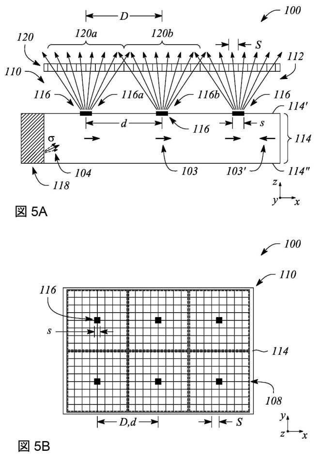
図5Aは、本明細書に記載する原理による実施形態による、実施例におけるマルチビー
ムバックライト110を含むヘッドトラッキングマルチビューディスプレイ100を示す
断面図である。図5Bは、本明細書に記載する原理による実施形態による、実施例におけ
るマルチビームバックライト110を含むヘッドトラッキングマルチビューディスプレイ
100を示す平面図である。図5Cは、本明細書に記載する原理による実施形態による、
実施例におけるマルチビームバックライト110を含むヘッドトラッキングマルチビュー
ディスプレイ100を示す斜視図である。図5cの斜視図は、本明細書における説明を容
易にするために、部分的に切り欠いて示してある。図5Aから図5Cは、以下でさらに述
べるように、マルチビームバックライト110の上方に位置決めされた光弁アレイ120
も示している。
FIG. 5A is a cross-sectional view showing a head tracking
It is a perspective view which shows the head tracking
Is also shown.
図5Aから図5Cに示すマルチビームバックライト110は、互いに異なる主要角度方
向を有する複数の外部結合光線112を(例えばライトフィールドとして)提供するよう
に構成される。特に、図5Aおよび図5Cに示すように、提供される複数の外部結合光線
112は、様々な実施形態によれば、マルチビームバックライト110から離れるように
、ヘッドトラッキングマルチビューディスプレイ100のそれぞれの視像方向に対応する
様々な主要角度方向に向けられる。さらに、外部結合光線112を(例えば本明細書で述
べるように光弁アレイ120の光弁を使用して)変調して、ヘッドトラッキングマルチビ
ューディスプレイ100による3Dコンテンツを有する情報のマルチビュー画像としての
表示を容易にすることができる。
The
図5Aから図5Cに示すように、マルチビームバックライト110は、光導波路114
を含む。光導波路114は、いくつかの実施形態によれば、平板光導波路とすることがで
きる。光導波路114は、光を、その光導波路114の長さに沿って、例えば太字矢印1
03で示す方向を有する誘導光104として誘導するように構成される。光導波路114
は、例えば光学導波路として構成される誘電体材料を含むことができる。誘電体材料は、
誘電体光学導波路を取り囲む媒質の第2の屈折率より大きい第1の屈折率を有することが
できる。この屈折率の差は、光導波路114の1つまたは複数の導波モードに応じて誘導
光104の全反射を促進するように設定される。
As shown in FIGS. 5A to 5C, the
including. The
It is configured to guide as guided light 104 having the direction indicated by 03.
Can include, for example, a dielectric material configured as an optical waveguide. Dielectric material is
It can have a first index of refraction that is greater than the second index of refraction of the medium surrounding the dielectric optical waveguide. This difference in refractive index is set to promote total reflection of the induced light 104 depending on one or more waveguide modes of the
いくつかの実施形態では、光導波路114は、光学的に透明な誘電体材料の延展された
実質的に平面状のシートを含むスラブまたは平板光学導波路とすることができる。様々な
実施例によれば、光導波路114の光学的に透明な材料は、これらに限定されるわけでは
ないが、様々な種類のガラス(例えばシリカガラス、アルミノケイ酸アルカリガラス、ホ
ウケイ酸ガラスなど)のうちの1つまたは複数、1つまたは複数の実質的に光学的に透明
なプラスチックまたはポリマー(例えばポリメタクリル酸メチルまたは「アクリルガラス
」、ポリカーボネートなど)、あるいはそれらの組合せなど、様々な誘電体材料のうちの
いずれかを含む、またはいずれかで構成することができる。いくつかの実施例では、光導
波路114は、光導波路114の表面(例えば頂面および底面の一方または両方)の少な
くとも一部分の上にクラッディング層(図示せず)をさらに含むことがある。クラッディ
ング層を使用して、全反射をさらに促進することができる。
In some embodiments, the
さらに、いくつかの実施形態によれば、光導波路114は、光導波路114の第1の表
面114’(例えば「前」面または側)と第2の表面114’’(例えば「後」面または
側)の間で非ゼロ伝搬角で誘導光104を誘導するように構成される。誘導光104は、
光導波路114の第1の表面114’と第2の表面114’’の間で非ゼロ伝搬角で反射
または「バウンド」することによって伝搬することができる(ただし伝搬方向は太字矢印
103が示す伝搬方向である)。いくつかの実施形態では、様々な色の光を含む誘導光1
04の複数の光線を、様々な色に固有の非ゼロ伝搬角のそれぞれ対応する角度で、光導波
路114によって誘導することができる。なお、図示を簡潔にするために、非ゼロ伝搬角
は、図5Aから図5Cには示していないことに留意されたい。
Further, according to some embodiments, the
It can propagate by reflecting or "bounding" between the first surface 114'and the second surface 114' of the
A plurality of light rays of 04 can be guided by the
本明細書で定義する「非ゼロ伝搬角」は、光導波路114の表面(例えば第1の表面1
14’または第2の表面114’’)に対する相対的な角度である。さらに、非ゼロ伝搬
角は、本明細書に記載する原理によれば、ゼロより大きく、かつ光導波路114内の全反
射の臨界角未満である。例えば、誘導光104の非ゼロ伝搬角は、約10度から約50度
の間とすることができ、いくつかの例では約20度から約40度の間とすることができ、
あるいは約25度から約35度の間とすることができる。例えば、非ゼロ伝搬角は、約3
0度とすることができる。他の例では、非ゼロ伝搬角は、約20度、または約25度、ま
たは約35度とすることができる。さらに、特定の実施態様では、その非ゼロ伝搬角が光
導波路114内の全反射の臨界角未満になるように選択されている限り、特定の非ゼロ伝
搬角を(例えば任意に)選択することができる。
The “non-zero propagation angle” defined herein is the surface of the optical waveguide 114 (eg, the first surface 1).
14'or the angle relative to the second surface 114''). Further, the non-zero propagation angle is greater than zero and less than the critical angle of total internal reflection within the
Alternatively, it can be between about 25 degrees and about 35 degrees. For example, the non-zero propagation angle is about 3
It can be 0 degrees. In another example, the non-zero propagation angle can be about 20 degrees, or about 25 degrees, or about 35 degrees. Further, in certain embodiments, a particular non-zero propagation angle is selected (eg, optionally) as long as its non-zero propagation angle is selected to be less than the critical angle of total internal reflection within the
光導波路114内の誘導光104は、非ゼロ伝搬角(例えば約30〜35度)で光導波
路114に導入または結合する(coupled into)ことができる。レンズ、ミラーまたはそ
れに類する反射器(例えば傾斜コリメート反射器)、およびプリズム(図示せず)のうち
の1つまたは複数によって、例えば非ゼロ伝搬角で光を誘導光104として光導波路11
4の入力端部に結合する(coupling … into)のを容易にすることができる。誘導光10
4は、光導波路114に結合される(coupled into)と、一般に入力端部から離れること
ができる方向(例えば図5Aのx軸に沿った向きの太字矢印103で示す方向)に光導波
路114に沿って伝搬する。
The guided light 104 in the
It is possible to facilitate coupling… into the input end of 4. Guided
4 is coupled into the
さらに、光を光導波路114に結合することによって生成される誘導光104すなわち
誘導光線は、本明細書に記載する原理によれば、視準光線である。本明細書では、「視準
光」または「視準光線」は、一般に、その放射線がその光線(例えば誘導光104)内で
互いに実質的に平行である光線として定義される。さらに、視準光線から発散または散乱
する光放射線は、本明細書の定義では、視準光線の一部とはみなされない。いくつかの実
施形態では、マルチビームバックライト110は、上述のようにレンズ、反射器またはミ
ラーなどのコリメータ(例えば傾斜コリメート反射器)を含んで、例えば光源からの光を
視準することができる。いくつかの実施形態では、光源がコリメータを含む。光導波路1
14に供給される視準光は、誘導される視準光線である。誘導光104は、様々な実施形
態では、視準因子σに従って、または視準因子σを有するように視準することができる。
Further, the guided
The collimation light supplied to 14 is a guided collimation ray. The induction light 104 can, in various embodiments, collimate according to or to have a sigma factor σ.
いくつかの実施形態では、光導波路114は、誘導光104を「リサイクル」するよう
に構成されることがある。特に、光導波路の全長に沿って誘導された誘導光104は、そ
の長さに沿って太字矢印103’で示す別の異なる伝搬方向に方向変更されることがある
。例えば、光導波路114は、光源に隣接する入力端部の反対側の光導波路114の端部
に反射器(図示せず)を含むことがある。反射器は、誘導光104をリサイクル誘導光と
して入力端部に向かって反射して戻すように構成することができる。このように誘導光を
リサイクルすることによって、誘導光104を以下で述べるようにマルチビーム要素が複
数回利用できるようにすることにより、マルチビームバックライト110の輝度(例えば
外部結合光線112の強度)を高めることができる。
In some embodiments, the
図5Aでは、リサイクル誘導光の別の伝搬方向を示す太字矢印103’(例えば負のx
方向に向く)は、前述の入力端部から光導波路114に導入された光導波路114内のリ
サイクル誘導光の全体としての伝搬方向を示している。あるいは(例えばリサイクル誘導
光に対して)、またはリサイクル誘導光に加えて、いくつかの実施形態では、例えば太字
矢印103が示す伝搬方向を有する前述の入力端部からの誘導光104に加えて、他の伝
搬方向(すなわち負のx方向に向いた太字矢印103’)を有する前述の入力端部に対向
する端部で光を光導波路114に導入することもできる。
In FIG. 5A, the bold arrow 103'(eg, negative x) indicates another direction of propagation of the recycled induction light.
(Directing in the direction) indicates the overall propagation direction of the recycled induction light in the
図5Aから図5Cに示すように、マルチビームバックライト110は、光導波路の全長
(x方向)に沿って互いに離間した複数のマルチビーム要素116をさらに含む。特に、
この複数の要素のマルチビーム要素116は、有限の間隔で互いに分離されており、光導
波路の全長に沿って個々の別個の要素を表している。すなわち、本明細書の定義では、こ
の複数のマルチビーム要素116は、有限(すなわち非ゼロ)の要素間距離(例えば有限
の中心間距離)に従って互いに離間している。さらに、この複数の要素のマルチビーム要
素116は、いくつかの実施形態によれば、一般に交差したり重なり合ったりするなどし
て互いに接触しない。すなわち、この複数の要素の各マルチビーム要素116は、一般に
、別個のものであり、他のマルチビーム要素116から分離している。
As shown in FIGS. 5A-5C, the
The
いくつかの実施形態によれば、この複数の要素のマルチビーム要素116は、1次元(
1D)アレイまたは2次元(2D)アレイのいずれかで配置されることがある。例えば、
この複数のマルチビーム要素116は、線形の1Dアレイとして配置することができる。
別の例では、この複数のマルチビーム要素116は、長方形の2Dアレイまたは円形の2
Dアレイとして配置することができる。さらに、このアレイ(すなわち1Dまたは2Dア
レイ)は、いくつかの例では、一定または一様なアレイとすることができる。特に、マル
チビーム要素116間の要素間距離(例えば中心間距離または間隔)は、アレイ全体にわ
たって実質的に一様または一定にすることができる。他の例では、マルチビーム要素11
6間の要素間距離は、アレイを横切る方向(y方向)および光導波路114の全長に沿っ
た方向(x方向)の一方または両方で変化することもある。
According to some embodiments, the
It may be arranged in either a 1D) array or a two-dimensional (2D) array. for example,
The plurality of
In another example, the plurality of
It can be arranged as a D array. Moreover, this array (ie, a 1D or 2D array) can be a constant or uniform array in some examples. In particular, the inter-element distance (eg, center-to-center distance or spacing) between the
The inter-element distance between the six may vary in one or both directions across the array (y direction) and along the overall length of the optical waveguide 114 (x direction).
様々な実施形態によれば、複数の要素のマルチビーム要素116は、誘導光104の一
部分を複数の外部結合光線112として外部結合するように構成される。特に、図5Aお
よび図5Cは、外部結合光線112を、光導波路114の第1の表面(または前面)11
4’から離れる向きに示す複数の発散する矢印として示している。さらに、様々な実施形
態によれば、マルチビーム要素116のサイズは、マルチビューピクセル中の「サブピク
セル」のサイズと同等である、すなわち光弁アレイ120中の光弁のサイズと同等である
。本明細書では、「サイズ」は、これらに限定されるわけではないが、長さ、幅、または
面積などを含む様々なかたちのいずれかで定義することができる。例えば、光弁(または
「サブピクセル」)のサイズは、その長さであることがあり、マルチビーム要素116の
それと同等であるサイズも、マルチビーム要素116の長さであることがある。別の例で
は、マルチビーム要素116の面積が光弁(または「サブピクセル」)の面積と同等であ
ることができるように、「サイズ」が面積を指すこともある。
According to various embodiments, the
It is shown as multiple divergent arrows pointing away from 4'. Moreover, according to various embodiments, the size of the
いくつかの実施形態では、マルチビーム要素のサイズがサブピクセルのサイズの約50
%と約200%の間になるように、マルチビーム要素116のサイズが光弁のサイズと同
等である。いくつかの実施形態では、マルチビーム要素のサイズを「s」で表し、サブピ
クセルのサイズを「S」で表した場合(例えば図5Aに示す)に、マルチビーム要素のサ
イズsは、数式(2)で与えることができる。
In some embodiments, the size of the multi-beam element is about 50 of the size of the subpixel.
The size of the
、サブピクセルのサイズの約70%以上、サブピクセルのサイズの約80%以上、または
サブピクセルのサイズの約90%以上である。いくつかの例では、マルチビーム要素は、
サブピクセルのサイズの約180%以下、サブピクセルのサイズの約160%以下、サブ
ピクセルのサイズの約140%以下、またはサブピクセルのサイズの約120%以下であ
る。いくつかの実施形態では、「同等であるサイズ」により、マルチビーム要素のサイズ
は、サブピクセルのサイズの約75%以上、約150%以下とすることができる。別の実
施形態では、マルチビーム要素のサイズがサブピクセルのサイズの約125%以下、約8
5%以上である場合に、マルチビーム要素116のサイズがサブピクセルと同等であると
することができる。いくつかの実施形態によれば、マルチビーム要素116および光弁の
同等であるサイズは、マルチビューディスプレイのビュー間の重複を低減する、またはい
くつかの実施形態では最小限に抑えながら、それと同時にマルチビューディスプレイのビ
ュー間の暗領域を低減する、またはいくつかの実施形態では最小限に抑えるように選択さ
れることがある。
It is about 180% or less of the subpixel size, about 160% or less of the subpixel size, about 140% or less of the subpixel size, or about 120% or less of the subpixel size. In some embodiments, the "equivalent size" allows the size of the multi-beam element to be about 75% or more and about 150% or less of the size of the subpixel. In another embodiment, the size of the multi-beam element is about 125% or less of the size of the subpixel, about 8
When it is 5% or more, it can be said that the size of the
上述のように、図5Aから図5Cは、マルチビームバックライト110の上方に位置決
めされた光弁アレイ120をさらに示している。このように位置決めされた光弁アレイ1
20は、複数の外部結合光線112を変調するように構成されている。図5Cでは、光弁
アレイ120を部分的に切り欠いて、光弁アレイ120の下にある光導波路114および
マルチビーム要素116が見えるようにしてある。
As mentioned above, FIGS. 5A-5C further show the
20 is configured to modulate a plurality of outer coupled rays 112. In FIG. 5C, the
図5Aから図5Cに示すように、様々な主要角度方向を有する外部結合光線112の異
なるそれぞれは、光弁アレイ120中のそれぞれ異なる光弁を通過し、それによって変調
することができる。さらに、光弁アレイ120の光弁は、サブピクセルに対応し、これら
の光弁のセットが、ヘッドトラッキングマルチビューディスプレイ100のマルチビュー
ピクセルに対応する。特に、光弁アレイ120の光弁の異なるセットは、マルチビーム要
素116の異なるそれぞれから外部結合光線112を受光してそれを変調する、すなわち
、図5Aから図5Cに示すように、各マルチビーム要素116ごとに、1つの一意的な光
弁のセットがある。
As shown in FIGS. 5A-5C, each of the different outer coupled
図5Aに示すように、第1の光弁セット120aは、第1のマルチビーム要素116a
から外部結合光線112を受光して変調するように構成され、第2の光弁セット120b
は、第2のマルチビーム要素116bから外部結合光線112を受光して変調するように
構成される。さらに、光弁アレイ120中の各光弁セット(例えば第1の光弁セット12
0aおよび第2の光弁セット120b)は、それぞれことなるマルチビューピクセル10
8(図5B参照)に対応し、光弁セット120a、120bの個々の光弁は、図5Aから
図5Cに示すようにそれぞれことなるマルチビューピクセル108のサブピクセルに対応
している。
As shown in FIG. 5A, the first light valve set 120a is the first
The second
Is configured to receive and modulate the outer coupled
0a and the second light valve set 120b) have different
Corresponding to 8 (see FIG. 5B), the individual light valves of the light valve sets 120a and 120b correspond to different sub-pixels of the
いくつかの実施形態では、マルチビーム要素116と対応するマルチビューピクセル1
08(例えば光弁のセット120a、120b)の間の関係は、1対1の関係であること
がある。すなわち、マルチビューピクセル108とマルチビーム要素116とが同数ずつ
存在することがある。図5Bに、例示を目的として1対1の関係を示すが、ここでは、各
マルチビューピクセル108(異なる光弁またはサブピクセルのセットを含む)が破線で
囲まれるものとして示してある。他の実施形態(図示せず)では、マルチビューピクセル
の数とマルチビーム要素の数が互いに異なることもある。
In some embodiments, the
The relationship between 08 (eg,
いくつかの実施形態では、一対の隣接するマルチビーム要素116間の要素間距離(例
えば中心間距離)は、例えば光弁セットで表される、対応する隣接する一対のマルチビュ
ーピクセル108間のピクセル間距離(例えば中心間距離)に等しいことがある。例えば
、図5Aに示すように、第1のマルチビーム要素116aと第2のマルチビーム要素11
6bの間の中心間距離dは、第1の光弁セット120aと第2の光弁セット120bの間
の中心間距離Dと実質的に等しい。他の実施形態(図示せず)では、マルチビーム要素1
16と対応する光弁セットの複数の対の相対中心間距離が異なることがあり、例えば、マ
ルチビーム要素116が、マルチビューピクセルを表す光弁セット間の間隔(すなわち中
心間距離D)より大きい、または小さい要素間間隔(すなわち中心間距離d)を有するこ
とがある。
In some embodiments, the inter-element distance (eg, center-to-center distance) between a pair of adjacent
The center-to-center distance d between 6b is substantially equal to the center-to-center distance D between the first light valve set 120a and the second
The relative center-to-center distances of a plurality of pairs of light valve sets corresponding to 16 may differ, for example, the
いくつかの実施形態では、マルチビーム要素116の形状は、マルチビューピクセル1
08の形状に類似している、すなわちマルチビューピクセル108に対応する光弁アレイ
120中の光弁のセット(または「サブアレイ」)の形状に類似している。例えば、マル
チビーム要素116は、実質的に正方形の形状を有することがあり、マルチビューピクセ
ル108(または対応する光弁のセットの配列)は、実質的に正方形であることがある。
別の例では、マルチビーム要素116は、実質的に長方形の形状を有することがある、す
なわち、幅または横方向寸法より大きな長さまたは長手方向寸法を有することがある。こ
の例では、このマルチビーム要素116に対応するマルチビューピクセル108は、実質
的に類似した長方形の形状を有することがある。図5Bは、正方形のマルチビーム要素1
16と、例えば破線で輪郭を示す光弁の正方形のセットを含むそれに対応する正方形のマ
ルチビューピクセルとを示す上面図または平面図である。さらに他の例(図示せず)では
、マルチビーム要素116および対応するマルチビューピクセルは、これらに限定される
わけではないが、三角形、六角形、および円形を含む、または少なくともこれらによって
近似される、様々な形状を有する。
In some embodiments, the shape of the
It resembles the shape of 08, i.e. resembles the shape of a set (or "subarray") of light valves in the
In another example, the
16 is a top view or plan view showing 16 and corresponding square multi-view pixels, including, for example, a set of squares of light valves contoured by dashed lines. In yet another example (not shown), the
様々な実施形態によれば、マルチビーム要素116は、誘導光104の一部分を外部結
合するように構成されたいくつかの異なる構造のうちのいずれかを含むことができる。例
えば、これらの異なる構造は、これらに限定されるわけではないが、回折格子、マイクロ
反射要素、マイクロ屈折要素、またはそれらの様々な組合せを含み得る。いくつかの実施
形態では、回折格子を含むマルチビーム要素116は、誘導光104の一部分を、様々な
主要角度方向を有する複数の外部結合光線112として回折的に光導波路114から外部
結合するように構成される。別の実施形態では、マイクロ反射要素を含むマルチビーム要
素116は、誘導光の一部分を、複数の外部結合光線112として光導波路114から反
射的に外部結合するように構成される。他の実施形態では、マイクロ屈折要素を含むマル
チビーム要素116は、誘導光の一部分を、複数の外部結合光線112として光導波路1
14から、屈折によって、または屈折を用いて外部結合する(すなわち誘導光の一部分を
屈折的に外部結合する)ように構成される。
According to various embodiments, the
From 14, it is configured to be externally coupled by refraction or by refraction (ie, a portion of the induced light is refractarily externally coupled).
図6Aは、本明細書に記載する原理による実施形態による、実施例におけるマルチビー
ム要素116を含むマルチビームバックライト110の一部分を示す断面図である。図6
Bは、本明細書に記載する原理による別の実施形態による、実施例におけるマルチビーム
要素116を含むマルチビームバックライト110の一部分を示す断面図である。特に、
図6Aから図6Bは、光導波路114内に回折格子を含むマルチビームバックライト11
0のマルチビーム要素116を示している。回折格子は、誘導光104の一部分を、複数
の外部結合光線112として光導波路114から回折的に外部結合するように構成される
。回折格子は、回折フィーチャ間隔あるいは回折フィーチャまたは格子ピッチ(すなわち
回折格子の回折フィーチャのピッチまたは間隔)だけ互いに離間した複数の回折フィーチ
ャを含む。この間隔またはピッチは、誘導光の一部分の回折的な外部結合を提供するよう
に構成される。様々な実施形態によれば、回折格子の回折フィーチャの間隔または格子ピ
ッチは、波長未満である(すなわち誘導光104の波長未満である)ことがある。
FIG. 6A is a cross-sectional view showing a part of the
B is a cross-sectional view showing a portion of the
6A to 6B show a multi-beam backlight 11 including a diffraction grating in the
The
いくつかの実施形態では、マルチビーム要素116の回折格子は、光導波路114の表
面に位置する、またはその表面に隣接して位置することがある。例えば、回折格子は、図
6Aに示すように、光導波路114の第1の表面114’にある、または第1の表面11
4’に隣接していることがある。光導波路の第1の表面114’に位置する回折格子は、
誘導光の一部分を第1の表面114’を通して外部結合光線112として回折的に外部結
合するように構成された伝送モード回折格子とすることができる。別の例では、図6Bに
示すように、回折格子は、光導波路114の第2の表面114’’に位置する、または第
2の表面114’’に隣接して位置することがある。第2の表面114’’に位置すると
きには、回折格子は、反射モード回折格子とすることができる。反射モード回折格子とし
て、回折格子は、誘導光の一部分を回折し、かつ回折した誘導光の一部分を第1の表面1
14’に向かって反射して、回折的に外部結合された光線112として第1の表面114
’を通して発出するように構成される。他の実施形態(図示せず)では、回折格子は、例
えば伝送モード回折格子および反射モード回折格子の一方または両方として、光導波路1
14の表面の間に位置することがある。なお、本明細書に記載するいくつかの実施形態で
は、外部結合光線112の主要角度方向は、光導波路の表面で光導波路114から出る外
部結合光線112による屈折の影響を含むことがあることに留意されたい。例えば、図6
Bは、限定ではなく例示を目的として、外部結合光線112が第1の表面114’を通っ
て出るときの屈折率の変化による外部結合光線112の屈折(すなわち屈曲)を示してい
る。また、以下で述べる図7Aおよび図7Bも参照されたい。
In some embodiments, the grating of the
May be adjacent to 4'. The diffraction grating located on the first surface 114'of the optical waveguide is
A transmission mode diffraction grating configured to diffractically externally couple a portion of the induced light as an externally coupled
The
It is configured to issue through'. In another embodiment (not shown), the diffraction grating is an optical waveguide 1 as, for example, one or both of a transmission mode diffraction grating and a reflection mode diffraction grating.
It may be located between the surfaces of 14. In some embodiments described herein, the principal angular direction of the externally coupled
B shows the refraction (ie, bending) of the outer coupled
いくつかの実施形態によれば、回折格子の回折フィーチャは、互いに離間した溝および
リッジの一方または両方を含むことがある。溝またはリッジは、光導波路114の材料を
含み、例えば、光導波路114の表面に形成されることがある。別の例では、溝またはリ
ッジは、例えば光導波路114の表面上の別の材料の膜または層など、光導波路の材料以
外の材料で構成されることもある。
According to some embodiments, the diffraction features of the grating may include one or both of the grooves and ridges separated from each other. Grooves or ridges include the material of the
いくつかの実施形態では、マルチビーム要素116の回折格子は、回折フィーチャの間
隔が回折格子全体にわたって実質的に一定または不変である、一様な回折格子である。他
の実施形態では、回折格子は、チャープ回折格子である。定義では、「チャープ」回折格
子は、チャープ回折格子の幅または長さにわたって変化する回折フィーチャの回折間隔(
すなわち格子ピッチ)を示す、または有する、回折格子である。いくつかの実施形態では
、チャープ回折格子は、距離と共に線形に変化する回折フィーチャの間隔のチャープを有
する、または示すことがある。したがって、チャープ回折格子は、定義では、「線形チャ
ープ」回折格子である。他の実施形態では、マルチビーム要素116のチャープ回折格子
は、回折フィーチャ間隔の非線形チャープを示すことがある。これらに限定されるわけで
はないが、指数チャープ、対数チャープ、または別の実質的に不均一または無作為ではあ
るが単調に変化するチャープなど、様々な非線形チャープを使用することができる。これ
らに限定されるわけではないが、正弦波形チャープあるいは三角形または鋸歯形チャープ
などの非単調チャープを利用することもできる。これらのタイプのチャープのいずれかの
組合せを利用することもできる。
In some embodiments, the grating of the
That is, it is a diffraction grating that shows or has a lattice pitch). In some embodiments, the chirp grating has or may indicate a chirp of diffraction feature spacing that changes linearly with distance. Therefore, a chirp grating is, by definition, a "linear chirp" grating. In other embodiments, the chirp grating of the
図7Aは、本明細書に記載する原理による別の実施形態による、実施例におけるマルチ
ビーム要素116を含むマルチビームバックライト110の一部分を示す断面図である。
図7Bは、本明細書に記載する原理による別の実施形態による、実施例におけるマルチビ
ーム要素116を含むマルチビームバックライト110の一部分を示す断面図である。特
に、図7Aおよび図7Bは、マイクロ反射要素を含むマルチビーム要素116の様々な実
施形態を示す図である。マルチビーム要素116として使用される、またはマルチビーム
要素116内で使用されるマイクロ反射要素は、これらに限定されるわけではないが、反
射材料または反射材料層(例えば反射性金属)を利用する反射器、あるいは全反射(TI
R)に基づく反射器を含み得る。いくつかの実施形態(例えば例示を目的として図7Aか
ら図7Bに示す)によれば、マイクロ反射要素を含むマルチビーム要素116は、光導波
路114の表面(例えば第2の表面114’’)に位置する、またはその表面に隣接して
位置することがある。他の実施形態(図示せず)では、マイクロ反射要素は、光導波路1
14内で第1の表面114’と第2の表面114’’の間に位置することがある。
FIG. 7A is a cross-sectional view showing a portion of the
FIG. 7B is a cross-sectional view showing a portion of the
It may include a reflector based on R). According to some embodiments (eg, shown in FIGS. 7A-7B for illustration purposes), the
It may be located within 14 between the first surface 114'and the second surface 114'.
例えば、図7Aは、光導波路114の第2の表面114’’に隣接して位置する、例え
ばプリズムのファセットと同様であることもある反射ファセットを有するマイクロ反射要
素(例えば「プリズム状」マイクロ反射要素)を含むマルチビーム要素116を示してい
る。図示のプリズム状マイクロ反射要素のファセットは、誘導光104の一部分を光導波
路114から出るように反射する(すなわち反射的に結合する(reflectively couple)
)ように構成される。ファセットは、誘導光104の伝搬方向に対して斜めである、また
は傾斜していて(すなわち傾斜角を有する)、例えば誘導光の一部分を光導波路114か
ら出るように反射することができる。ファセットは、様々な実施形態によれば、(例えば
図7Aに示すように)光導波路114内に反射性材料を使用して形成されることもあるし
、あるいは第2の表面114’’のプリズム状空洞の表面であることもある。プリズム状
空洞を利用するときには、いくつかの実施形態では、空洞の表面における屈折率の変化が
反射(例えばTIR反射)をもたらすこともあるし、あるいはファセットを形成する空洞
表面を反射性材料でコーティングして反射をもたらすこともある。
For example, FIG. 7A shows a micro-reflective element (eg, a “prism-like” micro-reflection) with reflective facets located adjacent to a
). The facet is beveled or tilted (ie, has a tilt angle) with respect to the propagation direction of the guided
別の例では、図7Bは、これに限定されるわけではないが、半球状マイクロ反射要素な
ど、湾曲表面を有するマイクロ反射要素を含むマルチビーム要素116を示している。い
くつかの例では、マイクロ反射要素の湾曲表面は、実質的に平滑であることがある。マイ
クロ反射要素の特定の表面湾曲は、例えば誘導光104が接触する湾曲表面上の入射点に
応じて様々な方向に誘導光の一部分を反射するように構成することができる。図7Aおよ
び図7Bに示すように、光導波路114から反射的に外部結合される誘導光の一部分は、
第1の表面114’から出る、または発出される。図7Aのプリズム状マイクロ反射要素
と同様に、図7Bのマイクロ反射要素は、限定ではなく例示を目的として図7Bに示すよ
うに、光導波路114内の反射性材料、または第2の表面114’’に形成された空洞(
例えば半球状空洞)とすることができる。図7Aおよび図7Bは、限定ではなく例示を目
的として、矢印103、103’で示す2つの伝搬方向を有する誘導光104も示してい
る。誘導光104の2つの伝搬方向を使用することにより、例えば、複数の外部結合光線
112に実質的に対称な主要角度方向の分布を与えることを容易にすることができる。
In another example, FIG. 7B shows a
Exit or exit from the first surface 114'. Similar to the prismatic microreflecting element of FIG. 7A, the microreflecting element of FIG. 7B is a reflective material within the
For example, a hemispherical cavity). 7A and 7B also show guided light 104 having two propagation directions indicated by
図8は、本明細書に記載する原理による別の実施形態による、実施例におけるマルチビ
ーム要素116を含むマルチビームバックライト110の一部分を示す断面図である。特
に、図8は、マイクロ屈折要素を含むマルチビーム要素116を示している。様々な実施
形態によれば、マイクロ屈折要素は、光導波路114から誘導光104の一部分を屈折的
に外部結合するように構成される。すなわち、マイクロ屈折要素は、図8に示すように、
(例えば回折または反射に対して)屈折を利用して、誘導光の一部分を外部結合光線11
2として光導波路114から外部結合するように構成される。マイクロ屈折要素は、これ
らに限定されるわけではないが、半球形、長方形、プリズム形(すなわち傾斜したファセ
ットを有する形状)など、様々な形状を有することができる。様々な実施形態によれば、
マイクロ屈折要素は、例えば図示のように光導波路114の表面(例えば第1の表面11
4’)から延びる、または突出することもあるし、あるいは表面の空洞(図示せず)であ
ることもある。さらに、マイクロ屈折要素は、いくつかの実施形態では、光導波路114
の材料を含むこともある。他の実施形態では、マイクロ屈折要素は、光導波路の表面に隣
接する、またはいくつかの例では光導波路の表面と接触する、別の材料を含むこともある
。
FIG. 8 is a cross-sectional view showing a portion of the
Using refraction (eg for diffraction or reflection), a portion of the induced light is externally coupled to the ray 11
As No. 2, it is configured to be externally coupled from the
The microrefractive element is, for example, the surface of the optical waveguide 114 (for example, the first surface 11) as shown in the drawing.
It may extend or project from 4'), or it may be a surface cavity (not shown). In addition, the microrefractive element, in some embodiments, is an
May also contain materials. In other embodiments, the microrefractive element may include another material that is adjacent to the surface of the optical waveguide or, in some cases, in contact with the surface of the optical waveguide.
図5Aおよび図5Cを再度参照すると、マルチビームバックライト110は、いくつか
の実施形態では、光源118をさらに含むことがある。光源118は、非ゼロ伝搬角で光
導波路114内を誘導される光を提供するように構成される。特に、光源118は、光導
波路114の入口表面または端部(入力端部)に隣接して位置することがある。様々な実
施形態では、光源118は、例えば上述したように、これらに限定されるわけではないが
、1つまたは複数の発光ダイオード(LED)またはレーザ(例えばレーザダイオード)
など、実質的に任意の光の源を含むことができる。いくつかの実施形態では、光源118
は、特定の色で表される狭帯域スペクトルを有する実質的に単色の光を生成するように構
成された発光体を含むことができる。特に、単色光の色は、特定の色空間または色モデル
(例えば赤/緑/青(RGB)色モデル)の原色とすることができる。他の例では、光源
118は、実質的に広帯域または多色の光を提供するように構成された実質的に広帯域の
光源であることもある。例えば、光源118は、白色光を提供することができる。いくつ
かの実施形態では、光源118は、異なる色の光を提供するように構成された複数の異な
る発光体を含むことがある。これらの異なる発光体は、その異なる色の光のそれぞれに対
応する、誘導光104の異なる色固有の非ゼロ伝搬角を有する光を提供するように構成す
ることができる。
With reference to FIGS. 5A and 5C again, the
It can include virtually any source of light, such as. In some embodiments,
Can include a illuminant configured to produce substantially monochromatic light having a narrow band spectrum represented by a particular color. In particular, the color of monochromatic light can be the primary color of a particular color space or color model (eg, red / green / blue (RGB) color model). In another example, the
いくつかの実施形態では、光源118は、コリメータをさらに含むことがある。コリメ
ータは、光源118の発光体のうちの1つまたは複数から実質的に視準されていない光を
受光するように構成されることがある。コリメータは、この実質的に視準されていない光
を視準光に変換するようにさらに構成される。特に、いくつかの実施形態では、コリメー
タは、非ゼロ伝搬角を有し、所定の視準因子σに従って視準された視準光を提供すること
ができる。さらに、様々な色の発光体を利用するときには、コリメータは、様々な色固有
の非ゼロ伝搬角のうちの1つまたは両方を有し、かつ様々な色固有の視準因子を有する視
準光を提供するように構成することができる。コリメータは、上述のように、視準光線を
光導波路114に伝達して誘導光104として伝搬するようにさらに構成される。
In some embodiments, the
いくつかの実施形態では、誘導光の非ゼロ伝搬角および視準因子のうちの一方または両
方が、ヘッドトラッキングマルチビューディスプレイ100の複数の光線112の発出パ
ターンを調節するように設定することができる。特に、非ゼロ伝搬角は、発出パターンを
ユーザに向かって傾斜させる(または選択的に向ける)ように設定することができる。例
えば、第1の非ゼロ伝搬角は、第1の場所Aのユーザに向かって実質的に向けられた光線
112の発出パターンを提供するように構成することができ、第2の非ゼロ伝搬角は、例
えば図4Aから図4Bを参照して上述したように、第2の場所Bのユーザに向かって発出
パターンを向けるように構成することができる。図9Aから図9Bは、ヘッドトラッキン
グ発出パターンの別の例を与える図である。
In some embodiments, one or both of the non-zero propagation angle of the induced light and the collimation factor can be configured to adjust the emission pattern of the plurality of
特に、図9Aは、本明細書に記載する原理による実施形態による、実施例におけるヘッ
ドトラッキングマルチビューディスプレイ100を示す断面図である。図9Bは、本明細
書に記載する原理による実施形態による、別の実施例における図9Aのヘッドトラッキン
グマルチビューディスプレイ100を示す断面図である。図9Aおよび図9Bは、マルチ
ビームバックライトの光導波路内の誘導光の異なる非ゼロ伝搬角に基づく外部結合光線1
12の異なる発出パターンの例を示している。図9Aから図9Bでは、ヘッドトラッキン
グマルチビューディスプレイ100は、マルチビームバックライト110、および光弁ア
レイ120を含む。いくつかの実施形態では、ヘッドトラッキングマルチビューディスプ
レイ100は、図5Aから図5Cを参照して上述したヘッドトラッキングマルチビューデ
ィスプレイ100と実質的に同様である。例えば、マルチビームバックライト110は、
図9Aから図9Bに示すように、破線で描写する発出パターンを有する複数の光線112
を光弁アレイ120に提供するように構成される。
In particular, FIG. 9A is a cross-sectional view showing the head tracking
Twelve examples of different emission patterns are shown. In FIGS. 9A-9B, the head tracking
As shown in FIGS. 9A-9B, a plurality of
Is configured to provide to the
図9Aでは、ユーザは、光弁アレイ120またはヘッドトラッキングマルチビューディ
スプレイ100の中心の実質的に前方にある(すなわちその中心に対して中心に位置する
)第1の場所Aに位置している。ヘッドトラッキングマルチビューディスプレイ100か
らの発出パターンは、第1の場所Aのユーザを実質的に(例えば傾斜なしで)指すように
構成される。例えば、マルチビームバックライト110の光導波路114内の誘導光10
4は、第1の非ゼロ伝搬角γ1で伝搬して、図9Aに示すように、発出パターンを第1の
場所Aに向ける、または方向付けることができる。
In FIG. 9A, the user is located at a first location A that is substantially in front of (ie, centered with respect to) the center of the
4 can propagate at the first non-zero propagation angle γ 1 and direct or orient the emission pattern towards the first location A, as shown in FIG. 9A.
図9Bでは、ユーザは、場所Aと比較して光弁アレイ120またはヘッドトラッキング
マルチビューディスプレイ100の中心の片側に(例えば傾斜角で)実質的にずれている
(すなわちその中心に対して中心に位置していない)第2の場所に移動している、または
位置している。図9Bに示す複数の光線112の発出パターンは、第1の場所Aに関する
発出パターンと比較して傾斜しているので、第2の場所Bのユーザを実質的に指すように
構成される。この例では、光導波路114内の誘導光104は、第2の非ゼロ伝搬角γ2
で伝搬して、図9Bに示すように、第2の場所Bに向かって発出パターンに傾斜を与える
ことができる。
In FIG. 9B, the user is substantially offset (ie, centered relative to) one side (eg, at an angle of inclination) of the center of the
Can propagate in and give the emission pattern a slope towards the second location B, as shown in FIG. 9B.
様々な実施形態では、第1の場所Aに向けられた発出パターンは、1次ビューセット(
すなわち誘導光の第1の非ゼロ伝搬角γ1によって提供される1次ビューセット)に対応
する光線112’の第1のセットを含む。さらに、第2の場所Bに向かって傾斜した傾斜
発出パターンは、1次ビューセットに対応する光線112’の第1のセットのサブセット
と、2次ビュー(すなわち誘導光の第2の非ゼロ伝搬角γ2によって提供される2次ビュ
ー)に対応する第2の光線112’’とを含むことができる。この傾斜発出パターンは、
上述のように、拡張ビューセットを表すことができる。
In various embodiments, the ejection pattern directed to the first location A is the primary view set (
That is, it includes a first set of rays 112'corresponding to the first non-zero propagation angle γ 1 of the induced light). In addition, the tilted emission pattern tilted towards the second location B is a subset of the first set of rays 112'corresponding to the primary view set and the secondary view (ie, the second non-zero propagation of the guided light). A second ray 112'' corresponding to the secondary view) provided by the angle γ 2 can be included. This inclined ejection pattern is
As mentioned above, it can represent an extended view set.
いくつかの実施形態では、マルチビームバックライト110は、誘導光104の伝搬方
向(すなわち太字矢印103、103’)に対して直交する光導波路114を通る方向の
光に対して実質的に透明になるように構成される。特に、いくつかの実施形態では、光導
波路114および離間した複数のマルチビーム要素116が、光が光導波路114、具合
的には第1の表面114’および第2の表面114’’の両方を通過することを可能にす
る。透明度は、少なくとも部分的には、マルチビーム要素116の比較的小さなサイズ、
およびマルチビーム要素116の比較的大きな要素間間隔(例えばマルチビューピクセル
と1対1の対応)の両方によって高めることができる。
In some embodiments, the
And can be enhanced by both the relatively large inter-element spacing of the multi-beam elements 116 (eg, a one-to-one correspondence with multi-view pixels).
本明細書に記載する原理のいくつかの実施形態によれば、ヘッドトラッキングマルチビ
ューディスプレイシステムが提供される。このヘッドトラッキングマルチビューディスプ
レイシステムは、シーンを表す3D画像またはマルチビュー画像を提供する、または「表
示する」ように構成される。特に、マルチビュー画像は、そのマルチビュー画像に関連付
けられた複数の異なる「ビュー」として提供される。この異なるビューが、例えば、表示
されているマルチビュー画像中に情報の「裸眼」(例えば自動立体視)表現を提供するこ
とができる。さらに、様々な実施形態によれば、ヘッドトラッキングマルチビューディス
プレイシステムのユーザの異なる位置または場所(例えば頭部の位置)に対して異なるビ
ューのセットを提供することができる。
According to some embodiments of the principles described herein, a head tracking multi-view display system is provided. The head tracking multi-view display system is configured to provide or "display" a 3D or multi-view image representing a scene. In particular, a multi-view image is provided as a plurality of different "views" associated with the multi-view image. This different view can provide, for example, a "naked eye" (eg, automatic stereoscopic) representation of the information in the displayed multi-view image. Further, according to various embodiments, different sets of views can be provided for different positions or locations (eg, head positions) of the user of the head tracking multi-view display system.
図10は、本明細書に記載する原理による実施形態による、実施例におけるヘッドトラ
ッキングマルチビューディスプレイシステム200を示すブロック図である。ヘッドトラ
ッキングマルチビューディスプレイシステム200は、異なる視像方向の異なるビューに
従ってマルチビュー画像を表示するように構成される。特に、ヘッドトラッキングマルチ
ビューディスプレイシステム200から発出される光線を使用して、マルチビュー画像を
表示し、この光線は、異なるビューのピクセル(すなわち異なるビューピクセル)に対応
することができる。異なるビュー、すなわち異なる視像方向は、図10では、ヘッドトラ
ッキングマルチビューディスプレイシステム200から出る矢印202として示してある
。以下で述べるように、矢印202は、ヘッドトラッキングマルチビューディスプレイシ
ステム200から発出される光線も表している。
FIG. 10 is a block diagram showing a head tracking
図10に示すヘッドトラッキングマルチビューディスプレイシステム200は、マルチ
ビューディスプレイ210を含む。マルチビューディスプレイ210は、シーンの複数の
ビュー(例えば矢印202)をマルチビュー画像として提供するように構成される。様々
な実施形態によれば、この複数のビューは、シーンの1次ビューのセットと、この1次ビ
ューセットに角度的に隣接するシーン視点を表す2次ビューとを含む。本明細書で述べて
いるように、2次ビュー(またはいくつかの実施形態では複数の2次ビュー)を1次ビュ
ーセットのビューのサブセットと組み合わせて、拡張ビューセットを提供することができ
る。さらに、ヘッドトラッキングマルチビューディスプレイシステム200の1次ビュー
セット、2次ビューセット、および拡張ビューセットは、いくつかの実施形態によれば、
上述したヘッドトラッキングマルチビューディスプレイ100に関連して上述した対応す
るビューセットおよびビューと実質的に同様であることがある。図10では、1次ビュー
は、実線矢印202’で示してあり、2次ビューは、破線矢印202’’で示してある。
The head tracking
It may be substantially similar to the corresponding view sets and views described above in connection with the head tracking
ヘッドトラッキングマルチビューディスプレイシステム200のマルチビューディスプ
レイ210は、1次ビューセット、および2次ビューのうちの1つまたは複数の両方を提
供するように構成することができる様々な異なるマルチビューディスプレイのうちのいず
れを実質的に含むこともできる。例えば、マルチビューディスプレイ210は、これらに
限定されるわけではないが、マルチビーム回折格子型マルチビューディスプレイ、または
レンズ状またはレンズアレイ型マルチビューディスプレイなどのマルチビューディスプレ
イとすることができる。本明細書では、定義では、「マルチビーム回折格子型マルチビュ
ーディスプレイ」は、マルチビーム回折格子のアレイを利用するマルチビーム回折格子型
のバックライトを含むマルチビューディスプレイである。また、本明細書の定義では、レ
ンズ状またはレンズアレイ型マルチビューディスプレイは、異なる視像方向のビューを提
供するレンズアレイを含むマルチビューディスプレイである。
The
他の実施形態では、マルチビューディスプレイ210は、マルチビーム要素形マルチビ
ューディスプレイであることもある。特に、ヘッドトラッキングマルチビューディスプレ
イシステム200のマルチビューディスプレイ210は、いくつかの実施形態によれば、
上述のヘッドトラッキングマルチビューディスプレイ100と実質的に同様であってよい
。例えば、マルチビューディスプレイ210は、複数のビューの異なる視像方向に対応す
る異なる主要角度方向を有する複数の発出または外部結合された光線を提供するように構
成されたマルチビームバックライトを含むことができる。マルチビューディスプレイ21
0は、例えば複数の外部結合光線を変調して複数のビューを提供するように構成された光
弁アレイをさらに含むこともある。さらに、マルチビューディスプレイ210は、ヘッド
トラッキングマルチビューディスプレイ100に関連して上述した光源118などの光源
をさらに含むこともある。
In other embodiments, the
It may be substantially the same as the head tracking
0 may further include, for example, a light valve array configured to modulate a plurality of outer coupled rays to provide multiple views. Further, the
これらの実施形態のいくつかによれば、ヘッドトラッキングマルチビューディスプレイ
システム200のマルチビームバックライトは、上述のマルチビームバックライト110
と実質的に同様であってよい。例えば、マルチビームバックライトは、光導波路の長さに
沿った伝搬方向に光を誘導するように構成された光導波路を含むことがあり、光導波路の
長さに沿って互いに離間したマルチビーム要素のアレイをさらに含むこともある。マルチ
ビーム要素アレイのマルチビーム要素は、誘導光の一部分を、異なる主要角度方向を有す
る複数の外部結合光線として光導波路から外部結合するように構成することができる。マ
ルチビーム要素アレイのマルチビーム要素は、マルチビーム要素116と実質的に同様で
あってよく、光導波路は、例えば光導波路114と実質的に同様であってよい。
According to some of these embodiments, the multi-beam backlight of the head tracking
May be substantially the same as. For example, a multi-beam backlight may include an optical waveguide configured to guide light in a propagation direction along the length of the optical waveguide, with multi-beam elements spaced apart from each other along the length of the optical waveguide. May also include an array of. The multi-beam elements of the multi-beam element array can be configured to externally couple a portion of the induced light from the optical waveguide as a plurality of externally coupled rays with different principal angular directions. The multi-beam elements of the multi-beam element array may be substantially similar to the
いくつかの実施形態では、マルチビーム要素のサイズは、光弁アレイの光弁のサイズと
同等であることがある。さらに、光弁は、ディスプレイのマルチビューピクセルのサブピ
クセルのサイズと実質的に同等であることがある。さらに、マルチビーム要素は、光導波
路に光学的に接続されて誘導光の一部分を外部結合する回折格子、マイクロ反射要素、お
よびマイクロ屈折要素のうちの1つまたは複数を含むことがある。いくつかの実施形態で
は、マルチビーム要素アレイの隣接するマルチビーム要素間の要素間距離は、隣接するマ
ルチビューピクセル間のピクセル間距離に対応する。さらに、マルチビューピクセルは、
個々のマルチビーム要素に対応する光弁アレイ内の光弁のセットを表す。
In some embodiments, the size of the multi-beam element may be comparable to the size of the light valve in the light valve array. In addition, the light valve may be substantially equivalent in size to the subpixels of the display's multi-view pixels. Further, the multi-beam element may include one or more of a diffraction grating, a micro-reflecting element, and a micro-refractive element that are optically connected to an optical waveguide to externally couple a portion of the induced light. In some embodiments, the inter-element distance between adjacent multi-beam elements in a multi-beam element array corresponds to the inter-pixel distance between adjacent multi-view pixels. In addition, multi-view pixels
Represents a set of light valves in a light valve array that corresponds to an individual multi-beam element.
再度図10を参照すると、ヘッドトラッキングマルチビューディスプレイシステム20
0は、ヘッドトラッカ220をさらに含む。ヘッドトラッカ220は、マルチビューディ
スプレイ210に対するユーザの場所を決定するように構成される。第1の決定された場
所では、マルチビューディスプレイ210は、1次ビューのセットを提供するように構成
される。さらに、第2の決定された場所では、マルチビューディスプレイ210は、2次
ビューと、1次ビューセットのビューのサブセットとを含む拡張ビューセットを提供する
ように構成される。図10に示すように、ヘッドトラッカ220は、一点鎖線で示すマル
チビューディスプレイ210の前方の領域222のユーザ(例えばユーザの頭部)の位置
をトラッキングするように構成することができる。「の前方」は、マルチビューディスプ
レイ210の発光表面または画像ビュースクリーンに隣接していることを意味する。
With reference to FIG. 10 again, the head tracking
0 further includes the
様々な実施形態によれば、ヘッドトラッキング(すなわちユーザの場所のトラッキング
)を提供する様々なデバイス、システム、および回路のうちのいずれでも、ヘッドトラッ
キングマルチビューディスプレイシステム200のヘッドトラッカ220として利用する
ことができる。例えば、いくつかの実施形態では、ヘッドトラッカ220は、マルチビュ
ーディスプレイ210のビュースクリーンに対してユーザの画像を取り込むように構成さ
れたカメラを含むことがある。さらに、ヘッドトラッカ220は、マルチビューディスプ
レイ210のビュースクリーンに対して取り込まれた画像内のユーザの場所を決定するよ
うに構成された画像プロセッサ(または画像プロセッサとしてプログラムされた汎用コン
ピュータ)を含むこともある。決定された場所は、例えば、上述した第1の決定された場
所Aおよび第2の決定された場所Bのうちの一方に対応することもある。マルチビューデ
ィスプレイ210のビュースクリーンに対するユーザの場所は、これらに限定されるわけ
ではないが、例えば画像認識またはパターンマッチングなどの様々な技術を使用して、取
り込まれた画像から画像プロセッサが決定することができる。ヘッドトラッカ220の出
力を使用して、マルチビューディスプレイ210の動作(例えば光弁アレイによる光線の
変調)を修正することができる。例えば、決定されたユーザの場所を、マルチビューディ
スプレイ210のプロセッサおよび光弁ドライバ(例えばドライバ回路)のうちの一方ま
たは両方に提供して、マルチビューディスプレイ210からの発出パターンをユーザの場
所に対応するように調整することもできる。ヘッドトラッカ220の実施態様のその他の
例は、これらに限定されるわけではないが、Kinect(登録商標)オブジェクトトラ
ッキングシステムなど、様々な2次元(2D)および3次元(3D)オブジェクトトラッ
キングシステムのうちの任意のものを含み得る。Kinect(登録商標)は、米国ワシ
ントン州RedmondのMicrosoft社の登録商標である。
According to various embodiments, any of the various devices, systems, and circuits that provide head tracking (ie, tracking the user's location) will be utilized as the
上述のように、いくつかの実施形態では、ヘッドトラッキングマルチビューディスプレ
イシステム200のマルチビューディスプレイ210は、光源をさらに含むこともある。
光源は、マルチビューディスプレイ210のための光の源として作用するように構成され
る。特に、これらの実施形態のいくつか(図10には図示せず)では、光源は、非ゼロ伝
搬角で光導波路に光を提供するように構成されることがあり、いくつかの実施形態では、
例えば、視準因子に従って視準されて、光導波路内の誘導光の所定の角度幅を提供する。
いくつかの実施形態では、光源は、ヘッドトラッカ220からの入力に応答して、マルチ
ビューディスプレイ210から発出される光の発出パターンをユーザに向かって傾斜させ
るようにさらに構成されることもある。発出パターンの傾斜、すなわち発光の「傾斜角」
は、これらの実施形態では、ヘッドトラッカ220によって決定されたユーザの場所に対
応する。例えば、光源は、マルチビームバックライトの光導波路を照明するために使用さ
れる光源であることもある。光源から提供される光導波路内を伝搬する光の角度が、マル
チビームバックライトから発出される光線の傾斜角を決定することもある。この発出角の
傾斜により、いくつかの実施形態によれば、2次ビューの生成を容易にする、または強化
することもできる。
As mentioned above, in some embodiments, the
The light source is configured to act as a source of light for the
For example, it is collimated according to a collimation factor to provide a predetermined angular width of guided light in the optical waveguide.
In some embodiments, the light source may be further configured to tilt the emission pattern of light emitted from the
Corresponds to the user's location determined by the
本明細書に記載する原理の他の実施形態によれば、ヘッドトラッキングを利用したマル
チビュー表示動作の方法が提供される。図11は、本明細書に記載する原理による実施形
態による実施例におけるヘッドトラッキングを利用したマルチビュー表示動作の方法30
0を示す流れ図である。図11に示すように、ヘッドトラッキングを利用したマルチビュ
ー表示動作の方法300は、マルチビューディスプレイを使用してシーンの複数のビュー
を提供するステップを含む。様々な実施形態によれば、この複数のビューは、シーンの1
次ビューのセットと、その1次ビューセットに角度的に隣接するシーン視点を表す2次ビ
ューとを含む。
According to another embodiment of the principles described herein, a method of multi-view display operation utilizing head tracking is provided. FIG. 11 shows a
It is a flow chart which shows 0. As shown in FIG. 11, the
It includes a set of next views and a secondary view that represents the scene viewpoints that are angularly adjacent to the primary view set.
様々な実施形態によれば、複数のビューを提供する(310)マルチビューディスプレ
イは、1次ビューのセットおよび2次ビューの両方を提供することができる実質的に任意
のマルチビューディスプレイまたはマルチビューディスプレイシステムとすることができ
る。例えば、このマルチビューディスプレイは、これらに限定されるわけではないが、マ
ルチビーム要素型マルチビューディスプレイ、マルチビーム回折格子型マルチビューディ
スプレイ、あるいはレンズ上またはレンズアレイ型マルチビューディスプレイなどのマル
チビューディスプレイとすることができる。いくつかの実施形態では、マルチビューディ
スプレイは、上述したヘッドトラッキングマルチビューディスプレイ100と実質的に同
様であってもよい。
According to various embodiments, a (310) multi-view display that provides multiple views can provide both a set of primary views and a secondary view of virtually any multi-view display or multi-view. It can be a display system. For example, this multi-view display is not limited to these, but is a multi-view display such as a multi-beam element type multi-view display, a multi-beam diffraction grating type multi-view display, or a lens-on-lens or lens array type multi-view display. Can be. In some embodiments, the multi-view display may be substantially similar to the head tracking
特に、いくつかの実施形態では、マルチビューディスプレイは、光導波路と、マルチビ
ーム要素と、複数の光弁とを含むことがある。これらの実施形態では、複数のビューを提
供するステップ(310)は、光導波路の長さに沿った伝搬方向に光を誘導するステップ
を含むことがある。光導波路は、例えば平板光導波路とすることができる。複数のビュー
を提供するステップ(310)はマルチビーム要素を用いて誘導光の一部分を光導波路か
ら外部結合して、マルチビューディスプレイのそれぞれの異なる視像方向に対応する異な
る主要角度方向を有する複数の外部結合光線を提供するステップをさらに含むこともある
。いくつかの実施形態では、マルチビーム要素は、光導波路に光学的に接続されて誘導光
の一部分を外部結合する回折格子、マイクロ反射要素、およびマイクロ屈折要素のうちの
1つまたは複数を含むことがある。マルチビーム要素は、例えばマルチビーム要素のアレ
イの一部であってもよい。これらの実施形態では、複数のビューを提供するステップ(3
10)は、複数の光弁を使用して外部結合光線を変調して、シーンの複数のビューをマル
チビュー画像として提供するステップをさらに含む。光弁は、例えば、マルチビーム要素
のアレイを備える光導波路の表面に隣接してアレイ状に配列することができる。いくつか
の実施形態では、マルチビーム要素のサイズは、光弁アレイの光弁のサイズと同等である
。
In particular, in some embodiments, the multi-view display may include an optical waveguide, a multi-beam element, and a plurality of light valves. In these embodiments, the step (310) of providing the plurality of views may include guiding light in a propagation direction along the length of the optical waveguide. The optical waveguide can be, for example, a flat plate optical waveguide. The step (310) of providing multiple views is to externally couple a portion of the induced light from an optical waveguide using a multi-beam element to have multiple major angular directions corresponding to different visual directions of the multi-view display. It may further include a step of providing an outer coupled ray of light. In some embodiments, the multi-beam element comprises one or more of a diffraction grating, a micro-reflecting element, and a micro-refractive element that are optically connected to an optical waveguide to externally couple a portion of the induced light. There is. The multi-beam element may be, for example, part of an array of multi-beam elements. In these embodiments, the steps of providing multiple views (3)
10) further comprises the step of using a plurality of light valves to modulate the outer coupled rays to provide a plurality of views of the scene as a multi-view image. The light valves can be arranged in an array adjacent to the surface of an optical waveguide comprising an array of multi-beam elements, for example. In some embodiments, the size of the multi-beam element is comparable to the size of the light valve in the light valve array.
図11に示すように、ヘッドトラッキングを利用したマルチビュー表示動作の方法30
0は、マルチビューディスプレイに対するユーザの場所を決定するステップ(320)と
、決定したユーザの場所に応じてユーザに対して表示または提供するビューセットを選択
するステップとをさらに含む。様々な実施形態によれば、1次ビューセットは、決定され
たユーザの第1の場所に対して選択され、拡張ビューセットは、決定されたユーザの第2
の場所に対して選択される。定義では、拡張ビューセットは、2次ビューと、1次ビュー
セットのビューのサブセットとを含む。マルチビューディスプレイは、ヘッドトラッキン
グを利用したマルチビュー表示動作の方法300による決定した場所およびビュー選択に
従って、1次ビューセットおよび拡張ビューセットを提供する。
As shown in FIG. 11, a
0 further includes a step (320) of determining a user's location with respect to the multi-view display and a step of selecting a view set to display or provide to the user depending on the determined user's location. According to various embodiments, the primary view set is selected for the determined user's first location and the extended view set is the determined user's second location.
Selected for the location of. By definition, an extended view set includes a secondary view and a subset of the views in the primary view set. The multi-view display provides a primary view set and an extended view set according to the location and view selection determined by
換言すれば、マルチビュー表示動作の方法300は、マルチビューディスプレイに対す
る(あるいはマルチビューディスプレイのスクリーン、またはマルチビューディスプレイ
によって提供されるビューに対する)ユーザの場所を決定する(320)。マルチビュー
表示動作の方法300は、ユーザが第1の場所にいると決定されるか第2の場所にいると
決定されるか(320)に応じて、1次ビューセットまたは拡張ビューセットを選択的に
提供する。特に、ユーザが第1の場所(例えばマルチビューディスプレイの前方)にいる
と決定されたときには、マルチビューディスプレイは、1次ビューのセットを提供する。
さらに、ユーザが第2の場所にいる(例えばマルチビューディスプレイの片側に実質的に
ずれている)と決定された(320)ときには、マルチビューディスプレイは、2次ビュ
ーを含む拡張ビューセットを提供する。したがって、マルチビューディスプレイは、決定
(320)したユーザの場所に応じて1次ビューセットまたは拡張ビューセットを含むよ
うに提供(310)した複数のビューを適合または調整する。
In other words,
Further, when it is determined (320) that the user is in a second location (eg, substantially offset to one side of the multi-view display), the multi-view display provides an extended view set that includes a secondary view. .. Therefore, the multi-view display fits or adjusts a plurality of views provided (310) to include a primary view set or an extended view set depending on the location of the determined (320) user.
いくつかの実施形態では、ユーザの場所を決定するステップ(320)は、ヘッドトラ
ッカを使用することを含む。これらの実施形態のいくつかでは、ヘッドトラッカは、ヘッ
ドトラッキングマルチビューディスプレイシステム200のヘッドトラッカ220と実質
的に同様であってよい。例えば、ヘッドトラッカは、カメラおよび画像プロセッサを含む
ことがある。この例では、ユーザの場所を決定するステップ(320)は、カメラを用い
てユーザの画像を取り込むステップと、画像プロセッサを用いて取り込んだ画像内のユー
ザの位置を確立するステップとを含むことがある。様々な実施形態によれば、この確立さ
れる位置が、決定(320)される場所である。例えば、確立される位置は、決定された
第1の場所および決定された第2の場所のうちの一方に対応することがある。
In some embodiments, the step (320) of determining a user's location involves using a head tracker. In some of these embodiments, the head tracker may be substantially similar to the
いくつかの実施形態(図示せず)では、マルチビュー表示動作の方法300は、マルチ
ビューディスプレイから発出される光の発出パターンを、ユーザの決定された場所に対応
するように傾斜させる(または選択的に向ける)ステップをさらに含む。発出パターンは
、例えば1次ビューセットまたは拡張ビューセットなど、特定のビューのセットに対応す
る光線を含むことがある。発出パターンは、決定された第1の場所のユーザに実質的に向
くように、または決定された第2の場所のユーザに実質的に向くように傾斜させることが
できる。いくつかの実施形態では、発出パターンの傾斜は、マルチビューディスプレイの
光導波路内の光の非ゼロ伝搬角を選択的に制御することによって行うことができる。例え
ば、第1の非ゼロ伝搬角は、第1の場所のユーザに実質的に向けられた光線の発出パター
ンを提供することがあり、第2の非ゼロ伝搬角は、第2の場所のユーザに実質的に向蹴ら
れた発出パターンを提供することがある。上述のように、ユーザの場所を決定する(32
0)ことができ、したがって、非ゼロ伝搬角の制御または選択は、例えばヘッドトラッカ
の出力を用いて行うことができる。さらに、いくつかの実施形態では、マルチビューディ
スプレイから発出される光の発出パターンを傾斜させるステップは、光源およびコリメー
タの一方または両方を使用して、光をそれぞれの非ゼロ伝搬角で光導波路に誘導光として
提供することを含む。いくつかの例では、光源は、ヘッドトラッキングマルチビューディ
スプレイ100に関連して上述した光源118と実質的に同様である。
In some embodiments (not shown),
0) It is possible and therefore control or selection of the non-zero propagation angle can be done using, for example, the output of the head tracker. Further, in some embodiments, the step of tilting the emission pattern of the light emitted from the multi-view display uses one or both of a light source and a collimator to direct the light into an optical waveguide at their respective non-zero propagation angles. Includes providing as induced light. In some examples, the light source is substantially similar to the
以上、1次ビューのセット、ならびに2次ビューと1次ビューセットのビューのサブセ
ットとを含む拡張ビューセットの両方を利用する、ヘッドトラッキングマルチビューディ
スプレイ、ヘッドトラッキングマルチビューディスプレイシステム、およびヘッドトラッ
キングを利用したマルチビュー表示動作の方法の実施例および実施形態について説明した
。上述の実施例は、単に本明細書に記載する原理を表現する多数の具体的な実施例のうち
の一部の例示に過ぎないことを理解されたい。当業者なら、以下の特許請求の範囲によっ
て定義される範囲を逸脱することなく、多数のその他の構成を容易に考案することができ
ることは明らかである。
A head-tracking multi-view display, a head-tracking multi-view display system, and a head-tracking that utilize both a set of primary views and an extended view set that includes a secondary view and a subset of the views of the primary view set. An embodiment and an embodiment of the method of the multi-view display operation used have been described. It should be understood that the above examples are merely exemplary of a number of specific examples expressing the principles described herein. It will be apparent to those skilled in the art that a number of other configurations can be easily devised without departing from the scope defined by the claims below.
10 マルチビューディスプレイ
12 スクリーン
14 ビュー
16 視像方向
20 光線
30 回折格子
40 光導波路
50 外部結合光線
100 ヘッドトラッキングマルチビューディスプレイ
102’ 1次ビューセット
102’’ 2次ビュー
108 マルチビューピクセル
110 マルチビームバックライト
112 光線
114 光導波路
116 マルチビーム要素
120 光弁アレイ
10
本開示は、以下の[1]から[22]を含む。
[1]ヘッドトラッキングマルチビューディスプレイであって、
マルチビュー画像の異なるビュー方向に対応する異なる主要角度方向を有する複数の光線を提供するように構成されたマルチビームバックライトと、
上記複数の光線のうちの光線を変調して、シーンの複数のビューを上記マルチビュー画像として提供するように構成された光弁アレイであり、上記複数のビューが、1次ビューのセット、および上記1次ビューセットに角度的に隣接する上記シーンの視点ビューを表す2次ビューを含む、光弁アレイとを含み、
上記ヘッドトラッキングマルチビューディスプレイが、ユーザのトラッキングされた場所に応じて、上記1次ビューセット、または上記2次ビューおよび上記1次ビューセットのビューのサブセットを含む拡張ビューセットのいずれかを選択的に提供するように構成される、ヘッドトラッキングマルチビューディスプレイ。
[2]上記マルチビームバックライトが、
その長さに沿った伝搬方向に光を誘導するように構成された光導波路と、
上記光導波路の長さに沿って互いに離間した複数のマルチビーム要素であり、上記複数のマルチビーム要素のうちのマルチビーム要素が、上記異なる主要角度方向を有する上記複数の光線として上記誘導光の一部分を上記光導波路から外部結合するように構成される、複数のマルチビーム要素とを含み、
上記マルチビーム要素のサイズが、上記光弁アレイの光弁のサイズと同等である、上記[1]に記載のヘッドトラッキングマルチビューディスプレイ。
[3]上記マルチビーム要素の上記サイズが、上記光弁のサイズの50%から200%の間である、上記[2]に記載のヘッドトラッキングマルチビューディスプレイ。
[4]上記マルチビーム要素が、上記誘導光の上記一部分を上記複数の光線として回折的に外部結合するように構成された回折格子を含む、上記[2]に記載のヘッドトラッキングマルチビューディスプレイ。
[5]上記マルチビーム要素が、マイクロ反射要素およびマイクロ屈折要素のうちの一方または両方を含み、上記マイクロ反射要素が、上記誘導光の一部分を反射的に外部結合するように構成され、上記マイクロ屈折要素が、上記誘導光の一部分を屈折的に外部結合するように構成される、上記[2]に記載のヘッドトラッキングマルチビューディスプレイ。
[6]上記マルチビーム要素が、上記光導波路の第1の表面および第2の表面の一方または両方に位置し、上記マルチビーム要素が、上記第1の表面を通して上記誘導光の位一部分を外部結合するように構成される、上記[2]に記載のヘッドトラッキングマルチビューディスプレイ。
[7]上記マルチビームバックライトの入力に光学的に結合される光源をさらに含み、上記光源が、非ゼロ伝搬角を有し、かつ/または所定のコリメーション因子に従ってコリメートされた誘導光として上記マルチビームバックライト内を誘導される光を提供するように構成される、上記[2]に記載のヘッドトラッキングマルチビューディスプレイ。
[8]上記非ゼロ伝搬角が、上記複数の光線の発出パターンを上記ユーザに向かって傾斜させるように設定される、上記[7]に記載のヘッドトラッキングマルチビューディスプレイ。
[9]上記[1]に記載のヘッドトラッキングマルチビューディスプレイを含むヘッドトラッキングマルチビューディスプレイシステムであって、上記マルチビューディスプレイに対する上記ユーザの場所を決定するように構成されたヘッドトラッカをさらに含み、決定された第1の場所にいるときには、上記ヘッドトラッキングマルチビューディスプレイが、上記1次ビューセットを選択的に提供するように構成され、決定された第2の場所にいるときには、上記ヘッドトラッキングマルチビューディスプレイが、上記拡張ビューセットを提供するように構成される、ヘッドトラッキングマルチビューディスプレイシステム。
[10]上記ヘッドトラッカが、
上記ユーザの画像を取り込むように構成されたカメラと、
上記取り込まれた画像内の上記ユーザの場所を決定するように構成された画像プロセッサとを含む、上記[9]に記載のヘッドトラッキングマルチビューディスプレイシステム。
[11]ヘッドトラッキングマルチビューディスプレイシステムであって、
シーンの複数のビューをマルチビュー画像として提供するように構成されたマルチビューディスプレイであり、上記複数のビューが、上記シーンの1次ビューのセット、および上記1次ビューセットに角度的に隣接するシーン視点を表す2次ビューを含む、マルチビューディスプレイと、
上記マルチビューディスプレイに対するユーザの場所を決定するように構成されたヘッドトラッカとを含み、決定された第1の場所にいるときには、上記マルチビューディスプレイが、上記1次ビューセットを提供するように構成され、決定された第2の場所にいるときには、上記マルチビューディスプレイが、上記2次ビューおよび上記1次ビューセットのビューのサブセットを含む拡張ビューセットを提供するように構成される、ヘッドトラッキングマルチビューディスプレイシステム。
[12]上記マルチビューディスプレイが、
上記複数のビューの異なるビュー方向に対応する異なる主要角度方向を有する複数の光線を提供するように構成されたマルチビームバックライトと、
上記複数の光線を変調して、上記複数のビューを提供するように構成された光弁アレイとを含む、上記[11]に記載のヘッドトラッキングマルチビューディスプレイシステム。
[13]上記マルチビームバックライトが、
その長さに沿った伝搬方向に光を誘導するように構成された光導波路と、
上記光導波路の長さに沿って互いに離間したマルチビーム要素のアレイであり、上記マルチビーム要素アレイのマルチビーム要素が、上記異なる主要角度方向を有する上記複数の光線として上記誘導光の一部分を上記光導波路から外部結合するように構成される、マルチビーム要素のアレイとを含み、
上記マルチビーム要素のサイズが、上記光弁アレイの光弁のサイズと同等である、上記[12]に記載のヘッドトラッキングマルチビューディスプレイシステム。
[14]上記マルチビーム要素が、上記光導波路に光学的に接続されて上記誘導光の上記一部分を外部結合する回折格子、マイクロ反射要素、およびマイクロ屈折要素のうちの1つまたは複数を含む、上記[13]に記載のヘッドトラッキングマルチビューディスプレイシステム。
[15]上記マルチビーム要素アレイの隣接するマルチビーム要素間の要素間距離が、隣接するマルチビューピクセル間のピクセル間距離に対応し、マルチビューピクセルが、個々のマルチビーム要素に対応する上記光弁アレイ内の光弁のセットを表す、上記[13]に記載のヘッドトラッキングマルチビューディスプレイシステム。
[16]上記ヘッドトラッカが、
上記ユーザの画像を取り込むように構成されたカメラと、
上記取り込まれた画像内の上記ユーザの場所を決定するように構成された画像プロセッサとを含み、
上記決定された場所が、上記第1の場所および上記第2の場所のうちの一方に対応する、上記[11]に記載のヘッドトラッキングマルチビューディスプレイシステム。
[17]上記マルチビューディスプレイから発出される光の発出パターンを、上記ヘッドトラッカから提供される上記ユーザの決定された場所に向かって選択的に傾斜させるように構成された光源をさらに含む、上記[11]に記載のヘッドトラッキングマルチビューディスプレイシステム。
[18]ヘッドトラッキングを利用したマルチビュー表示動作の方法であって、
マルチビューディスプレイを用いてシーンの複数のビューを提供するステップであり、上記複数のビューが、1次ビューのセット、および上記1次ビューセットに角度的に隣接するシーン視点を表す2次ビューを含む、ステップと、
上記マルチビューディスプレイに対するユーザの場所を決定するステップであり、上記マルチビューディスプレイが、上記ユーザが第1の場所にいると決定されたときには上記1次ビューセットを選択的に提供し、上記ユーザが第2の場所にいると決定されたときには拡張ビューセットを選択的に提供する、ステップとを含み、
上記拡張ビューセットが、上記2次ビュー、および上記1次ビューセットのビューのサブセットを含む、方法。
[19]複数のビューを提供するステップが、
光導波路の長さに沿った伝搬方向に光を誘導するステップと、
マルチビーム要素を用いて上記誘導光の一部分を上記光導波路から外部結合して、上記マルチビューディスプレイのそれぞれ異なるビュー方向に対応する異なる主要角度方向を有する複数の外部結合光線を提供するステップと、
複数の光弁を用いて上記複数の外部結合光線を変調して、上記シーンの上記複数のビューをマルチビュー画像として提供するステップとを含み、
上記マルチビーム要素のサイズが、上記複数の光弁の光弁のサイズと同等である、上記[18]に記載のマルチビュー表示動作の方法。
[20]上記マルチビーム要素が、上記誘導光の上記一部分を外部結合するように上記光導波路に光学的に接続された回折格子、マイクロ反射要素、およびマイクロ屈折要素のうちの1つまたは複数を含む、上記[19]に記載のマルチビュー表示動作の方法。
[21]上記ユーザの場所を決定するステップが、
カメラを用いて上記ユーザの画像を取り込むステップと、
画像プロセッサを用いて上記取り込まれた画像内の上記ユーザの位置を確立するステップであり、上記確立される位置が、上記決定された第1の場所および上記決定された第2の場所のうちの一方に対応する、ステップとを含む、上記[18]に記載のマルチビュー表示動作の方法。
[22]上記マルチビューディスプレイから発出される光の発出パターンを、上記ユーザの上記決定された場所に対応するように傾斜させるステップをさらに含む、上記[18]に記載のマルチビュー表示動作の方法。
本明細書に記載する原理による実施例および実施形態の様々な特徴は、以下の詳細な説明を添付の図面と関連付けて参照すれば、より容易に理解することができる。これらの図面では、同じ参照番号は同じ構造要素を示している。
The present disclosure includes the following [1] to [22].
[1] A head tracking multi-view display.
With a multi-beam backlight configured to provide multiple rays with different principal angular directions corresponding to different view directions of the multi-view image,
A light valve array configured to modulate a ray of the plurality of rays to provide a plurality of views of the scene as the multi-view image, wherein the plurality of views are a set of primary views and a set of primary views. Includes a light valve array, including a secondary view representing a viewpoint view of the scene that is angularly adjacent to the primary view set.
The head-tracking multi-view display selectively selects either the primary view set or an extended view set that includes a subset of the secondary view and views of the primary view set, depending on where the user is tracked. A head tracking multi-view display configured to provide.
[2] The above multi-beam backlight
An optical waveguide configured to guide light in the propagation direction along its length,
A plurality of multi-beam elements separated from each other along the length of the optical waveguide, and the multi-beam elements among the plurality of multi-beam elements are the above-mentioned induced light as the plurality of light rays having different main angular directions. Includes a plurality of multi-beam elements configured to externally couple a portion from the optical waveguide.
The head tracking multi-view display according to the above [1], wherein the size of the multi-beam element is equivalent to the size of the light valve of the light valve array.
[3] The head tracking multi-view display according to [2] above, wherein the size of the multi-beam element is between 50% and 200% of the size of the light valve.
[4] The head tracking multi-view display according to the above [2], wherein the multi-beam element includes a diffraction grating configured to diffractically externally couple the portion of the induced light as the plurality of light rays.
[5] The multi-beam element includes one or both of a micro-reflecting element and a micro-refractive element, and the micro-reflecting element is configured to reflexively externally couple a portion of the induced light. The head tracking multi-view display according to the above [2], wherein the refracting element is configured to reflexively externally couple a part of the induced light.
[6] The multi-beam element is located on one or both of the first surface and the second surface of the optical waveguide, and the multi-beam element externals a part of the induced light through the first surface. The head tracking multi-view display according to [2] above, which is configured to be combined.
[7] The multi-beam includes a light source optically coupled to the input of the multi-beam backlight, and the light source has a non-zero propagation angle and / or is collimated according to a predetermined collimation factor. The head tracking multi-view display according to [2] above, which is configured to provide light guided through a beam backlight.
[8] The head tracking multi-view display according to [7], wherein the non-zero propagation angle is set so as to incline the emission patterns of the plurality of rays toward the user.
[9] A head tracking multi-view display system comprising the head-tracking multi-view display according to [1] above, further comprising a head tracker configured to determine the location of the user with respect to the multi-view display. The head tracking multi-view display is configured to selectively provide the primary view set when in a determined first location, and the head tracking multi when in a determined second location. A head tracking multi-view display system in which the view display is configured to provide the extended view set described above.
[10] The head tracker
A camera configured to capture the above user's image,
The head tracking multi-view display system according to [9] above, which includes an image processor configured to determine the location of the user in the captured image.
[11] A head tracking multi-view display system.
A multi-view display configured to provide a plurality of views of a scene as a multi-view image, wherein the plurality of views are angularly adjacent to a set of primary views of the scene and the primary view set. A multi-view display that includes a secondary view that represents the scene perspective,
The multi-view display is configured to provide the primary view set when in a determined first location, including a head tracker configured to determine the user's location with respect to the multi-view display. When in a determined second location, the multi-view display is configured to provide an extended view set that includes a subset of the views of the secondary view and the primary view set. View display system.
[12] The multi-view display is
A multi-beam backlight configured to provide a plurality of rays having different principal angular directions corresponding to different view directions of the plurality of views.
The head tracking multi-view display system according to [11] above, which includes an optical valve array configured to modulate the plurality of rays to provide the plurality of views.
[13] The multi-beam backlight
An optical waveguide configured to guide light in the propagation direction along its length,
It is an array of multi-beam elements separated from each other along the length of the optical waveguide, and the multi-beam elements of the multi-beam element array form a part of the guided light as the plurality of rays having different main angular directions. Includes an array of multi-beam elements configured to externally couple from the optical waveguide.
The head tracking multi-view display system according to [12] above, wherein the size of the multi-beam element is equivalent to the size of the light valve of the light valve array.
[14] The multi-beam element comprises one or more of a diffraction grating, a micro-reflecting element, and a micro-refractive element that are optically connected to the optical waveguide to externally couple the portion of the induced light. The head tracking multi-view display system according to the above [13].
[15] The inter-element distance between adjacent multi-beam elements of the multi-beam element array corresponds to the inter-pixel distance between adjacent multi-view pixels, and the multi-view pixels correspond to the individual multi-beam elements. The head tracking multi-view display system according to [13] above, which represents a set of light valves in a valve array.
[16] The head tracker
A camera configured to capture the above user's image,
Includes an image processor configured to determine the location of the user within the captured image.
The head tracking multi-view display system according to [11], wherein the determined location corresponds to one of the first location and the second location.
[17] Further including a light source configured to selectively tilt an emission pattern of light emitted from the multi-view display toward a user-determined location provided by the head tracker. The head tracking multi-view display system according to [11].
[18] A method of multi-view display operation using head tracking.
A step of providing multiple views of a scene using a multi-view display, wherein the plurality of views represent a set of primary views and a secondary view representing a scene perspective that is angularly adjacent to the primary view set. Including, steps and
A step of determining a user's location with respect to the multi-view display, wherein the multi-view display selectively provides the primary view set when the user is determined to be in the first location. Including steps, which selectively provide an extended view set when determined to be in a second location,
A method in which the extended view set comprises a subset of the views of the secondary view and the primary view set.
[19] The step of providing a plurality of views is
The step of guiding light in the propagation direction along the length of the optical waveguide,
A step of externally coupling a portion of the guided light from the optical waveguide using a multi-beam element to provide a plurality of externally coupled rays having different principal angular directions corresponding to different view directions of the multi-view display.
Including the step of modulating the plurality of outer coupled rays using a plurality of light valves to provide the plurality of views of the scene as a multi-view image.
The method of multi-view display operation according to the above [18], wherein the size of the multi-beam element is equivalent to the size of the light valves of the plurality of light valves.
[20] The multi-beam element comprises one or more of a diffraction grating, a micro-reflecting element, and a micro-refractive element that are optically connected to the optical waveguide so as to externally couple the portion of the induced light. The method of the multi-view display operation according to the above [19], including the method of the multi-view display operation.
[21] The step of determining the location of the above user is
Steps to capture the above user's image using a camera,
It is a step of establishing the position of the user in the captured image using an image processor, and the established position is one of the determined first place and the determined second place. The method of multi-view display operation according to the above [18], which includes a step corresponding to one of the above.
[22] The method of the multi-view display operation according to the above [18], further comprising a step of tilting the emission pattern of light emitted from the multi-view display so as to correspond to the above-determined location of the user. ..
Various features of examples and embodiments according to the principles described herein can be more easily understood by reference to the following detailed description in association with the accompanying drawings. In these drawings, the same reference numbers refer to the same structural elements.
本明細書に記載する原理による実施例および実施形態は、ユーザ位置または「ヘッドトラッキング」を利用するマルチビューまたは3次元(3D)画像ディスプレイを提供する。本明細書に記載する原理による実施形態は、マルチビューディスプレイを利用して、ユーザの位置に応じてマルチビュー画像によって表現されるシーンの様々なビューの様々なセットを提供することができる。特に、ユーザが第1の場所に位置しているときに、1次ビューのセットを提供することができる。このビューの1次セットは、ある視野角内でユーザにマルチビュー画像を提供するように構成される。さらに、ユーザが第2の場所に移動するとき、または第2の場所に位置しているときに、ビューの拡張セットを提供することができる。拡張ビューセットは、1次ビューおよび2次ビューのサブセットを含む。2次ビューは、ビューの1次セットの角度範囲に角度的に隣接するが実質的にその角度範囲の外にあるシーンの視方向またはビュー方向を表す。ユーザの異なる位置に対応する異なるビューセットを提供することにより、表示されているマルチビュー画像の有効視野(FOV)角を増大させることができる。FOV角を増大させることにより、例えば斜めの角度でマルチビュー画像を見るときに起こる可能性があるマルチビューまたは3次元(3D)画像の知覚のいわゆる「ジャンプ」または「反転視」を低減または緩和することができる。 Examples and embodiments according to the principles described herein provide a multi-view or three-dimensional (3D) image display that utilizes user position or "head tracking". Embodiments according to the principles described herein can utilize a multi-view display to provide different sets of different views of the scene represented by the multi-view image depending on the user's position. In particular, a set of primary views can be provided when the user is located in the first location. The primary set of views is configured to provide the user with a multi-view image within a viewing angle. In addition, an extended set of views can be provided when the user moves to or is located in a second location. The extended view set contains a subset of primary and secondary views. A secondary view represents the viewing or viewing direction of a scene that is angularly adjacent to, but substantially outside, the angular range of the primary set of views. By providing different view sets that correspond to different positions of the user, the effective field of view (FOV) angle of the displayed multi-view image can be increased. Increasing the FOV angle reduces or mitigates the so-called "jump" or "reversal" of perception of a multi-view or three-dimensional (3D) image that can occur, for example, when viewing a multi-view image at an oblique angle. can do.
本明細書では、「マルチビューディスプレイ」は、マルチビュー画像の様々なビューを様々なビュー方向で提供するように構成された電子ディスプレイまたはディスプレイシステムとして定義される。図1Aは、本明細書に記載する原理による実施形態による、1実施例のマルチビューディスプレイ10を示す斜視図である。図1Aに示すように、マルチビューディスプレイ10は、見る対象のマルチビュー画像を表示するスクリーン12を含む。マルチビューディスプレイ10は、このマルチビュー画像の様々なビュー14を、スクリーン12に対する様々なビュー方向16に提供する。ビュー方向16は、スクリーン12から様々な異なる主要角度方向に延びる矢印として示してあり、様々なビュー14は、それらの矢印(すなわちビュー方向16を示す矢印)の終端に網掛けした多角形として示してあり、また、4つのビュー14と4つのビュー方向16しか示していないが、全て例示を目的としてものであり、限定を目的としたものではない。なお、図1Aでは様々なビュー14がスクリーンの上方にあるものとして示してあるが、マルチビュー画像がマルチビューディスプレイ10に表示されたとき、これらのビュー14は、実際にはスクリーン12上、またはスクリーン12の近傍に見えることに留意されたい。ビュー14をスクリーン12の上方に示しているのは、単に説明を簡略にするためであり、これらのビュー方向16のうち特定のビュー14に対応する各ビュー方向からマルチビューディスプレイ10を見ていることを表すためのものである。図1Aは、また、「2次ビュー14’」も示している。図示の2次ビュー14’は、ビュー14(すなわちビュー14の1次セット)の角度範囲に角度的に隣接するが実質的にその角度範囲の外にある、このシーンの視点(a perspective of the scene)を表す、すなわち2次ビュー方向16’を有する。
As used herein, a "multi-view display" is defined as an electronic display or display system configured to provide different views of a multi-view image in different view directions. FIG. 1A is a perspective view showing a
マルチビューディスプレイのビュー方向、すなわちビュー方向に対応する方向を有する光線は、一般に、本明細書の定義では角度成分{θ、φ}で与えられる主要角度方向を有する。角度成分θは、本明細書では、光線の「高度成分」または「仰角」と呼ぶ。角度成分φは、光線の「方位成分」または「方位角」と呼ぶ。定義では、仰角θは、垂直平面(例えばマルチビューディスプレイスクリーンの平面に対して直交する面)内の角度であり、方位角φは、水平面(例えばマルチビューディスプレイスクリーン平面に対して平行な面)内の角度である。図1Bは、本明細書に記載する原理による実施形態による、実施例におけるマルチビューディスプレイのビュー方向(例えば図1Aのビュー方向16)に対応する特定の主要角度方向を有する光線20の角度成分{θ、φ}の図示である。さらに、光線20は、本明細書の定義では、特定の点から発出される、または放射する。すなわち、定義では、光線20は、マルチビューディスプレイ内の特定の原点に関連付けられた中心放射線を有する。図1Bは、光線(またはビュー方向)の原点Oも示している。
Multi-view display of the view direction, i.e. rays with a direction corresponding to the view direction is generally in the definitions herein has a major angular direction given by the angle component {θ, φ}. The angle component θ is referred to herein as the “altitude component” or “elevation angle” of the light beam. The angle component φ is called the “azimuth component” or “azimuth angle” of the light beam. By definition, elevation θ is an angle in a vertical plane (eg, a plane orthogonal to the plane of the multi-view display screen) and azimuth φ is a horizontal plane (eg, a plane parallel to the plane of the multi-view display screen). The angle inside. FIG. 1B shows the angular component of a
「マルチビューピクセル」は、本明細書では、マルチビューディスプレイの同様の複数の異なるビューのそれぞれの「ビュー」ピクセルを表すサブピクセルのセットとして定義される。特に、マルチビューピクセルは、マルチビュー画像の様々なビューのそれぞれのビューピクセルに対応する、またはマルチビュー画像の様々なビューのそれぞれのビューピクセルを表す、個々のサブピクセルを有することができる。さらに、マルチビューピクセルのサブピクセルは、本明細書の定義では、各サブピクセルが様々なビューのうちの対応するビューの所定のビュー方向と関連付けられるので、いわゆる「方向ピクセル」である。さらに、様々な実施例および実施形態によれば、マルチビューピクセルのサブピクセルによって表される様々なビューピクセルは、様々なビューのそれぞれにおいて、等価な、または少なくとも実質的には同様の位置または座標を有することができる。例えば、第1のマルチビューピクセルは、マルチビュー画像の様々なビューのそれぞれにおいて{x1、y1}に位置するビューピクセルに対応する個々のサブピクセルを有することがあり、第2のマルチビューピクセルは、様々なビューのそれぞれにおいて{x2、y2}に位置するビューピクセルに対応する個々のサブピクセルを有することがある、などである。 A "multi-view pixel" is defined herein as a set of sub-pixels that represent each "view" pixel of a plurality of similar and different views of a multi-view display. In particular, a multi-view pixel can have individual sub-pixels that correspond to the respective view pixels of the different views of the multi-view image or represent the respective view pixels of the different views of the multi-view image. Further, the sub-pixels of a multi-view pixel are so-called "direction pixels" as defined herein because each sub-pixel is associated with a predetermined view orientation of the corresponding view of the various views. Moreover, according to various examples and embodiments, the various view pixels represented by the subpixels of the multi-view pixel have equivalent, or at least substantially similar, positions or coordinates in each of the different views. Can have. For example, the first multi-view pixel may have individual sub-pixels corresponding to the view pixels located at {x 1 , y 1 } in each of the various views of the multi-view image, and the second multi-view Pixels may have individual sub-pixels corresponding to view pixels located at {x 2 , y 2 } in each of the various views, and so on.
いくつかの実施形態では、マルチビューピクセル中のサブピクセルの数が、マルチビューディスプレイのビューの数と等しいことがある。例えば、マルチビューピクセルは、64個の異なるビューを有するマルチビューディスプレイと関連付けられた64個のサブピクセルを提供することがある。別の例では、マルチビューディスプレイがビューの8×4アレイ(すなわち32個のビュー)を提供し、マルチビューピクセルが、32個のサブピクセル(すなわち各ビュー当たり1つ)を含むこともある。さらに、それぞれの異なるサブピクセルは、例えば上記の例では64個の異なるビューに対応する、または32個の異なるビューに対応するビュー方向のうちの異なる1つに対応する関連する方向(すなわち光線の主要角度方向)を有することができる。さらに、いくつかの実施形態によれば、マルチビューディスプレイのマルチビューピクセルの数は、マルチビューディスプレイのビュー中の「ビュー」ピクセル(すなわち選択されたビューを構成するピクセル)の数と実質的に等しいことがある。例えば、ビューが640×480個のビューピクセル(すなわち640×480ビュー解像度)を含む場合には、マルチビューディスプレイは、307200個のマルチビューピクセルを有することができる。別の例では、ビューが100×100個のビューピクセルを含む場合には、マルチビューディスプレイは、総数で10000(すなわち100×100=10000)個のマルチビューピクセルを含むことができる。 In some embodiments, the number of sub-pixels in a multi-view pixel may be equal to the number of views in a multi-view display. For example, a multi-view pixel may provide 64 sub-pixels associated with a multi-view display with 64 different views. In another example, a multi-view display may provide an 8x4 array of views (ie 32 views) and the multi-view pixels may contain 32 sub-pixels (ie 1 per view). Further, each different sub-pixel corresponds to, for example, 64 different views in the above example, or a related direction (ie, a ray of light) corresponding to a different one of the view directions corresponding to 32 different views. Can have a major angular direction). Further, according to some embodiments, the number of multi-view pixels in a multi-view display is substantially the number of "view" pixels (ie, the pixels that make up the selected view) in the view of the multi-view display. May be equal. For example, if the view contains 640 x 480 view pixels (ie, 640 x 480 view resolutions), the multi-view display can have 307,200 multi-view pixels. In another example, if the view contains 100 x 100 view pixels, the multi-view display can contain a total of 10000 (ie 100 x 100 = 10000) multi-view pixels.
本明細書では、「コリメータ」は、光をコリメートするように構成された実質的に任意の光学デバイスまたは装置として定義される。例えば、コリメータは、これらに限定されるわけではないが、コリメートミラーまたは反射器、コリメートレンズ、あるいはそれらの様々な組合せを含む可能性がある。いくつかの実施形態では、コリメート反射器を含むコリメータは、放物曲線または放物形を特徴とする反射表面を有することがある。別の例では、コリメート反射器は、成形放物線状反射器を含むことがある。「成形放物線状」とは、その成形放物線状反射器の湾曲した反射表面が、所定の反射特性(例えばコリメーション度)を実現するように決定されるように「真の」放物曲線から逸脱していることを意味する。コリメートレンズは、球形表面(例えば両凸球面レンズ)を含むことがある。 As used herein, a "collimator" is defined as virtually any optical device or device configured to collimate light. For example, collimators may include, but are not limited to, collimator mirrors or reflectors, collimator lenses, or various combinations thereof. In some embodiments, the collimator, including a collimator reflector, may have a reflective surface characterized by a parabolic curve or parabolic shape. In another example, the collimated reflector may include a molded parabolic reflector. "Molded parabolic" means that the curved reflective surface of the molded parabolic reflector deviates from the "true" parabolic curve so that it is determined to achieve a given reflection characteristic (eg, degree of collimation). It means that it is. The collimating lens may include a spherical surface (eg, a biconvex spherical lens).
様々な実施形態によれば、コリメータによって提供されるコリメーション量は、実施形態によって所定の程度または量において変化することがある。さらに、コリメータは、2つの直交する方向(例えば垂直方向および水平方向)の一方または両方にコリメーションを提供するように構成することができる。すなわち、コリメータは、いくつかの実施形態によれば、光のコリメーションを提供する2つの直交する方向のうちの一方または両方の形状を含むことがある。 According to various embodiments, the amount of collimator provided by the collimator may vary to a predetermined degree or amount depending on the embodiment. In addition, the collimator can be configured to provide collimation in one or both of the two orthogonal directions (eg, vertical and horizontal). That is, the collimator may include one or both of the two orthogonal directions that provide light collimation, according to some embodiments.
本明細書では、「コリメーション因子」は、光がコリメートされる程度として定義される。特に、コリメーション因子は、本明細書の定義では、コリメートされた光線内の光放射線の角度幅を定義する。例えば、コリメーション因子σは、コリメートされた光線内の光放射線の大部分が特定の角度幅(例えばコリメート光線の中心または主要角度方向の周りの±σ度)内にあるように指定することができる。コリメートされた光線の光放射線は、角度についてガウス分布を有することがあり、角度幅は、いくつかの実施例によれば、コリメートされた光線のピーク強度の2分の1によって決まる角度であることがある。 As used herein, a " collimation factor " is defined as the degree to which light is collimated. In particular, the collimation factor , as defined herein, defines the angular width of light radiation within a collimated ray. For example, the collimation factor σ can be specified such that most of the light radiation in the collimated rays is within a particular angular width (eg ± σ degrees around the center or major angular direction of the collimated rays). .. The light radiation of a collimated ray may have a Gaussian distribution with respect to the angle, and the angular width is an angle determined by half the peak intensity of the collimated ray, according to some embodiments. There is.
本明細書に記載する原理のいくつかの実施形態によれば、ヘッドトラッキングマルチビームディスプレイが提供される。図3は、本明細書に記載する原理による実施形態による、実施例におけるヘッドトラッキングマルチビューディスプレイ100を示す断面図である。ヘッドトラッキングマルチビューディスプレイ100は、シーンの複数のビューをマルチビュー画像すなわち表示マルチビュー画像として提供するように構成される。特に、この複数のビューは、ヘッドトラッキングマルチビューディスプレイ100によって、対応する複数のビュー方向に提供される。図3では、ビュー方向、すなわち複数のビューは、ヘッドトラッキングマルチビューディスプレイ100から延びる様々な角度方向を指す矢印102で示されている。
According to some embodiments of the principles described herein, a head tracking multi-beam display is provided. FIG. 3 is a cross-sectional view showing a head tracking
様々な実施形態によれば、ヘッドトラッキングマルチビューディスプレイ100によって提供される複数のビューは、1次ビューのセットを含む。例えば、図3の実線矢印102’は、1次ビューのセット、すなわち1次ビューの方向のセットを表すことができる。ヘッドトラッキングマルチビューディスプレイ100によって提供される複数のビューは、さらに、2次ビュー方向に2次ビューを含む。例えば、図3の破線矢印102’’は、2次ビューまたは2次ビュー方向を表すことができる。様々な実施形態によれば、本明細書の定義では、2次ビューは、1次ビューのセットの角度範囲に角度的に隣接するがその角度範囲の実質的に外にある、シーンの視点またはビュー方向を表す。特に、2次ビューは、本明細書の定義では、1次ビューセットによって画定される角度範囲、例えば図3の実線矢印102’によって画定される角度範囲の外部にある視野角を有するビュー方向に対応する。いくつかの実施形態では、ヘッドトラッキングマルチビューディスプレイ100は、複数の2次ビューを提供することができる。様々な実施形態によれば、ヘッドトラッキングマルチビューディスプレイ100は、1次ビューセットまたはビューの拡張セットのいずれかを選択的に提供するように構成される。ビューの拡張セットは、2次ビューと、1次ビューセットのビューのサブセットとを含む。
According to various embodiments, the plurality of views provided by the head tracking
図3を参照すると、図示のヘッドトラッキングマルチビューディスプレイ100は、マルチビームバックライト110を含む。マルチビームバックライト110は、様々な主要角度方向を有する複数の光線112を提供するように構成される。特に、光線112は、ヘッドトラッキングマルチビューディスプレイ100の、すなわちヘッドトラッキングマルチビューディスプレイ100によって表示されるマルチビュー画像の、様々なビュー方向に対応する、様々な主要角度方向を有することができる。例えば、図3の矢印102は、マルチビームバックライト110によって提供される光線112、すなわち様々なビュー方向に対応する光線112の様々な主要角度方向を表すこともできる。
Referring to FIG. 3, the illustrated head tracking
さらに、図3に示すように、複数の光線112は、第1のセットの光線112’と、第2のセットの光線112’’とを含む。図3では、第1のセットの光線112’は、実線矢印(すなわち実線矢印102)を用いて示され、第2のセットの光線112’’は、破線矢印(すなわち破線矢印102’’)を用いて示されている。第1のセットの光線112’は、1次ビューのセットのビュー方向に対応する主要角度方向を有する複数の光線の光線112を表す。第2のセットの光線112’’は、例えば、ヘッドトラッキングマルチビューディスプレイ100の様々な2次ビュー方向に対応する主要角度方向を有する複数の光線の光線112を表す。
Further, as shown in FIG. 3, the plurality of
図3を参照して上述したように、様々なビュー、すなわち1次ビューセット102aおよび拡張ビューセット102bの両方のビュー方向は、矢印102で表してある。具体的には、図4Aおよび図4Bでは、実線矢印102’は、1次ビューセット102aのビューすなわちビュー方向を表し、破線矢印102’’は、例えば拡張ビューセット102b内の2次ビューすなわち2次ビュー方向を表している。さらに、図4A〜図4Bでは、様々なビューまたはビュー方向は、左から右に向かって順番に大きくなる文字で特定され、文字「a」は第1のビューを表し、文字「b」は第2のビューを表す、というようになっている。図示のように、図4Aでは、1次ビューセット102aは、「a」から「h」で標識された8個のビューを含む。2次ビューは、図4Bでは、このシーンの9番目のビューを表し、「i」で標識されている。
As described above with reference to FIG. 3, the view directions of the various views, i.e. both the primary view set 102a and the
本明細書に記載する原理の様々な実施形態によれば、ヘッドトラッキングマルチビューディスプレイ100は、実質的にいかなるマルチビームバックライトでも含むことができる。特に、様々な実施形態によれば、マルチビュー画像の様々なビュー方向に対応する様々な主要角度方向を有する複数の光線112を提供するように構成された任意のバックライトを使用することができる。例えば、いくつかの実施形態では、マルチビームバックライト110は、マルチビーム回折格子に基づくことがある。他の実施形態では、ヘッドトラッキングマルチビューディスプレイ100のマルチビームバックライト110は、マルチビーム要素を含む。マルチビームバックライト110は、以下で述べるように、光導波路と、複数のマルチビーム要素とを含むことがある。
According to various embodiments of the principles described herein, the head tracking
図5Aから図5Cに示すマルチビームバックライト110は、互いに異なる主要角度方向を有する複数の外部結合光線112を(例えばライトフィールドとして)提供するように構成される。特に、図5Aおよび図5Cに示すように、提供される複数の外部結合光線112は、様々な実施形態によれば、マルチビームバックライト110から離れるように、ヘッドトラッキングマルチビューディスプレイ100のそれぞれのビュー方向に対応する様々な主要角度方向に向けられる。さらに、外部結合光線112を(例えば本明細書で述べるように光弁アレイ120の光弁を使用して)変調して、ヘッドトラッキングマルチビューディスプレイ100による3Dコンテンツを有する情報のマルチビュー画像としての表示を容易にすることができる。
The
さらに、光を光導波路114に結合することによって生成される誘導光104すなわち誘導光線は、本明細書に記載する原理によれば、コリメート光線である。本明細書では、「コリメート光」または「コリメート光線」は、一般に、その放射線がその光線(例えば誘導光104)内で互いに実質的に平行である光線として定義される。さらに、コリメート光線から発散または散乱する光放射線は、本明細書の定義では、コリメート光線の一部とはみなされない。いくつかの実施形態では、マルチビームバックライト110は、上述のようにレンズ、反射器またはミラーなどのコリメータ(例えば傾斜コリメート反射器)を含んで、例えば光源からの光をコリメートすることができる。いくつかの実施形態では、光源がコリメータを含む。光導波路114に供給されるコリメート光は、誘導されるコリメート光線である。誘導光104は、様々な実施形態では、コリメーション因子σに従って、またはコリメーション因子σを有するようにコリメートすることができる。
Further, the induced
いくつかの実施形態では、光源118は、コリメータをさらに含むことがある。コリメータは、光源118の発光体のうちの1つまたは複数から実質的にコリメートされていない光を受光するように構成されることがある。コリメータは、この実質的にコリメートされていない光をコリメート光に変換するようにさらに構成される。特に、いくつかの実施形態では、コリメータは、非ゼロ伝搬角を有し、所定のコリメーション因子σに従ってコリメートされたコリメート光を提供することができる。さらに、様々な色の発光体を利用するときには、コリメータは、様々な色固有の非ゼロ伝搬角のうちの1つまたは両方を有し、かつ様々な色固有のコリメーション因子を有するコリメート光を提供するように構成することができる。コリメータは、上述のように、コリメート光線を光導波路114に伝達して誘導光104として伝搬するようにさらに構成される。
In some embodiments, the
いくつかの実施形態では、誘導光の非ゼロ伝搬角およびコリメーション因子のうちの一方または両方が、ヘッドトラッキングマルチビューディスプレイ100の複数の光線112の発出パターンを調節するように設定することができる。特に、非ゼロ伝搬角は、発出パターンをユーザに向かって傾斜させる(または選択的に向ける)ように設定することができる。例えば、第1の非ゼロ伝搬角は、第1の場所Aのユーザに向かって実質的に向けられた光線112の発出パターンを提供するように構成することができ、第2の非ゼロ伝搬角は、例えば図4Aから図4Bを参照して上述したように、第2の場所Bのユーザに向かって発出パターンを向けるように構成することができる。図9Aから図9Bは、ヘッドトラッキング発出パターンの別の例を与える図である。
In some embodiments, one or both of the non-zero propagation angle of the induced light and the collimation factor can be configured to adjust the emission pattern of the plurality of
図10は、本明細書に記載する原理による実施形態による、実施例におけるヘッドトラッキングマルチビューディスプレイシステム200を示すブロック図である。ヘッドトラッキングマルチビューディスプレイシステム200は、異なるビュー方向の異なるビューに従ってマルチビュー画像を表示するように構成される。特に、ヘッドトラッキングマルチビューディスプレイシステム200から発出される光線を使用して、マルチビュー画像を表示し、この光線は、異なるビューのピクセル(すなわち異なるビューピクセル)に対応することができる。異なるビュー、すなわち異なるビュー方向は、図10では、ヘッドトラッキングマルチビューディスプレイシステム200から出る矢印202として示してある。以下で述べるように、矢印202は、ヘッドトラッキングマルチビューディスプレイシステム200から発出される光線も表している。
FIG. 10 is a block diagram showing a head tracking
ヘッドトラッキングマルチビューディスプレイシステム200のマルチビューディスプレイ210は、1次ビューセット、および2次ビューのうちの1つまたは複数の両方を提供するように構成することができる様々な異なるマルチビューディスプレイのうちのいずれを実質的に含むこともできる。例えば、マルチビューディスプレイ210は、これらに限定されるわけではないが、マルチビーム回折格子型マルチビューディスプレイ、またはレンズ状またはレンズアレイ型マルチビューディスプレイなどのマルチビューディスプレイとすることができる。本明細書では、定義では、「マルチビーム回折格子型マルチビューディスプレイ」は、マルチビーム回折格子のアレイを利用するマルチビーム回折格子型のバックライトを含むマルチビューディスプレイである。また、本明細書の定義では、レンズ状またはレンズアレイ型マルチビューディスプレイは、異なるビュー方向のビューを提供するレンズアレイを含むマルチビューディスプレイである。
The
他の実施形態では、マルチビューディスプレイ210は、マルチビーム要素形マルチビューディスプレイであることもある。特に、ヘッドトラッキングマルチビューディスプレイシステム200のマルチビューディスプレイ210は、いくつかの実施形態によれば、上述のヘッドトラッキングマルチビューディスプレイ100と実質的に同様であってよい。例えば、マルチビューディスプレイ210は、複数のビューの異なるビュー方向に対応する異なる主要角度方向を有する複数の発出または外部結合された光線を提供するように構成されたマルチビームバックライトを含むことができる。マルチビューディスプレイ210は、例えば複数の外部結合光線を変調して複数のビューを提供するように構成された光弁アレイをさらに含むこともある。さらに、マルチビューディスプレイ210は、ヘッドトラッキングマルチビューディスプレイ100に関連して上述した光源118などの光源をさらに含むこともある。
In other embodiments, the
上述のように、いくつかの実施形態では、ヘッドトラッキングマルチビューディスプレイシステム200のマルチビューディスプレイ210は、光源をさらに含むこともある。光源は、マルチビューディスプレイ210のための光の源として作用するように構成される。特に、これらの実施形態のいくつか(図10には図示せず)では、光源は、非ゼロ伝搬角で光導波路に光を提供するように構成されることがあり、いくつかの実施形態では、例えば、コリメーション因子に従ってコリメートされて、光導波路内の誘導光の所定の角度幅を提供する。いくつかの実施形態では、光源は、ヘッドトラッカ220からの入力に応答して、マルチビューディスプレイ210から発出される光の発出パターンをユーザに向かって傾斜させるようにさらに構成されることもある。発出パターンの傾斜、すなわち発光の「傾斜角」は、これらの実施形態では、ヘッドトラッカ220によって決定されたユーザの場所に対応する。例えば、光源は、マルチビームバックライトの光導波路を照明するために使用される光源であることもある。光源から提供される光導波路内を伝搬する光の角度が、マルチビームバックライトから発出される光線の傾斜角を決定することもある。この発出角の傾斜により、いくつかの実施形態によれば、2次ビューの生成を容易にする、または強化することもできる。
As mentioned above, in some embodiments, the
特に、いくつかの実施形態では、マルチビューディスプレイは、光導波路と、マルチビーム要素と、複数の光弁とを含むことがある。これらの実施形態では、複数のビューを提供するステップ(310)は、光導波路の長さに沿った伝搬方向に光を誘導するステップを含むことがある。光導波路は、例えば平板光導波路とすることができる。複数のビューを提供するステップ(310)はマルチビーム要素を用いて誘導光の一部分を光導波路から外部結合して、マルチビューディスプレイのそれぞれの異なるビュー方向に対応する異なる主要角度方向を有する複数の外部結合光線を提供するステップをさらに含むこともある。いくつかの実施形態では、マルチビーム要素は、光導波路に光学的に接続されて誘導光の一部分を外部結合する回折格子、マイクロ反射要素、およびマイクロ屈折要素のうちの1つまたは複数を含むことがある。マルチビーム要素は、例えばマルチビーム要素のアレイの一部であってもよい。これらの実施形態では、複数のビューを提供するステップ(310)は、複数の光弁を使用して外部結合光線を変調して、シーンの複数のビューをマルチビュー画像として提供するステップをさらに含む。光弁は、例えば、マルチビーム要素のアレイを備える光導波路の表面に隣接してアレイ状に配列することができる。いくつかの実施形態では、マルチビーム要素のサイズは、光弁アレイの光弁のサイズと同等である。 In particular, in some embodiments, the multi-view display may include an optical waveguide, a multi-beam element, and a plurality of light valves. In these embodiments, the step (310) of providing the plurality of views may include guiding light in a propagation direction along the length of the optical waveguide. The optical waveguide can be, for example, a flat plate optical waveguide. The step (310) of providing multiple views is to externally couple a portion of the induced light from an optical waveguide using a multi-beam element to have a plurality of different principal angular directions corresponding to different view directions of the multi-view display. It may further include a step of providing an outer coupling ray. In some embodiments, the multi-beam element comprises one or more of a diffraction grating, a micro-reflecting element, and a micro-refractive element that are optically connected to an optical waveguide to externally couple a portion of the induced light. There is. The multi-beam element may be, for example, part of an array of multi-beam elements. In these embodiments, the step of providing the plurality of views (310) further comprises the step of using the plurality of light valves to modulate the outer coupled rays to provide the plurality of views of the scene as a multi-view image. .. The light valves can be arranged in an array adjacent to the surface of an optical waveguide comprising an array of multi-beam elements, for example. In some embodiments, the size of the multi-beam element is comparable to the size of the light valve in the light valve array.
10 マルチビューディスプレイ
12 スクリーン
14 ビュー
16 ビュー方向
20 光線
30 回折格子
40 光導波路
50 外部結合光線
100 ヘッドトラッキングマルチビューディスプレイ
102’ 1次ビューセット
102’’ 2次ビュー
108 マルチビューピクセル
110 マルチビームバックライト
112 光線
114 光導波路
116 マルチビーム要素
120 光弁アレイ
10
Claims (22)
マルチビュー画像の異なる視像方向に対応する異なる主要角度方向を有する複数の光線
を提供するように構成されたマルチビームバックライトと、
前記複数の光線のうちの光線を変調して、シーンの複数のビューを前記マルチビュー画
像として提供するように構成された光弁アレイであり、前記複数のビューが、1次ビュー
のセット、および前記1次ビューセットに角度的に隣接する前記シーンの視点ビューを表
す2次ビューを含む、光弁アレイとを含み、
前記ヘッドトラッキングマルチビューディスプレイが、ユーザのトラッキングされた場
所に応じて、前記1次ビューセット、または前記2次ビューおよび前記1次ビューセット
のビューのサブセットを含む拡張ビューセットのいずれかを選択的に提供するように構成
される、ヘッドトラッキングマルチビューディスプレイ。 Head tracking multi-view display
With a multi-beam backlight configured to provide multiple rays with different principal angular directions corresponding to different viewing directions of the multi-view image,
A light valve array configured to modulate a ray of the plurality of rays to provide a plurality of views of the scene as the multi-view image, wherein the plurality of views are a set of primary views and a set of primary views. A light valve array including a secondary view representing a viewpoint view of the scene angularly adjacent to the primary view set.
The head-tracking multi-view display selectively selects either the primary view set or an extended view set that includes a subset of the secondary view and views of the primary view set, depending on where the user is tracked. A head tracking multi-view display configured to provide.
その長さに沿った伝搬方向に光を誘導するように構成された光導波路と、
前記光導波路の長さに沿って互いに離間した複数のマルチビーム要素であり、前記複数
のマルチビーム要素のうちのマルチビーム要素が、前記異なる主要角度方向を有する前記
複数の光線として前記誘導光の一部分を前記光導波路から外部結合するように構成される
、複数のマルチビーム要素とを含み、
前記マルチビーム要素のサイズが、前記光弁アレイの光弁のサイズと同等である、請求
項1に記載のヘッドトラッキングマルチビューディスプレイ。 The multi-beam backlight
An optical waveguide configured to guide light in the propagation direction along its length,
A plurality of multi-beam elements separated from each other along the length of the optical waveguide, and the multi-beam elements among the plurality of multi-beam elements are the plurality of light rays having the different main angular directions of the guided light. Includes a plurality of multi-beam elements configured to externally couple a portion from the optical waveguide.
The head tracking multi-view display according to claim 1, wherein the size of the multi-beam element is equivalent to the size of the light valve of the light valve array.
ある、請求項2に記載のヘッドトラッキングマルチビューディスプレイ。 The head tracking multi-view display according to claim 2, wherein the size of the multi-beam element is between 50% and 200% of the size of the light valve.
部結合するように構成された回折格子を含む、請求項2に記載のヘッドトラッキングマル
チビューディスプレイ。 The head tracking multi-view display according to claim 2, wherein the multi-beam element includes a diffraction grating configured to diffractically externally couple the portion of the induced light as the plurality of light rays.
は両方を含み、前記マイクロ反射要素が、前記誘導光の一部分を反射的に外部結合するよ
うに構成され、前記マイクロ屈折要素が、前記誘導光の一部分を屈折的に外部結合するよ
うに構成される、請求項2に記載のヘッドトラッキングマルチビューディスプレイ。 The multi-beam element comprises one or both of a micro-reflecting element and a micro-refractive element, the micro-refractive element is configured to reflexively externally couple a portion of the induced light, the micro-refractive element. The head tracking multi-view display according to claim 2, wherein a part of the induced light is refractively externally coupled.
方に位置し、前記マルチビーム要素が、前記第1の表面を通して前記誘導光の位一部分を
外部結合するように構成される、請求項2に記載のヘッドトラッキングマルチビューディ
スプレイ。 The multi-beam element is located on one or both of the first and second surfaces of the optical waveguide so that the multi-beam element externally couples a portion of the induced light through the first surface. 2. The head tracking multi-view display according to claim 2.
源が、非ゼロ伝搬角を有し、かつ/または所定の視準因子に従って視準された誘導光とし
て前記マルチビームバックライト内を誘導される光を提供するように構成される、請求項
2に記載のヘッドトラッキングマルチビューディスプレイ。 The multi-beam further comprises a light source optically coupled to the input of the multi-beam backlight, the light source having a non-zero propagation angle and / or as guided light collimated according to a predetermined collimation factor. The head tracking multi-view display according to claim 2, which is configured to provide light guided through a backlight.
うに設定される、請求項7に記載のヘッドトラッキングマルチビューディスプレイ。 The head tracking multi-view display according to claim 7, wherein the non-zero propagation angle is set to incline the emission patterns of the plurality of rays toward the user.
ングマルチビューディスプレイシステムであって、前記マルチビューディスプレイに対す
るユーザの場所を決定するように構成されたヘッドトラッカをさらに含み、決定された第
1の場所にいるときには、前記ヘッドトラッキングマルチビューディスプレイが、前記1
次ビューセットを選択的に提供するように構成され、決定された第2の場所にいるときに
は、前記ヘッドトラッキングマルチビューディスプレイが、前記拡張ビューセットを提供
するように構成される、ヘッドトラッキングマルチビューディスプレイシステム。 A first determined head tracking multi-view display system comprising the head tracking multi-view display according to claim 1, further comprising a head tracker configured to determine a user's location with respect to the multi-view display. When you are in the location of, the head tracking multi-view display is
The head-tracking multi-view display is configured to provide the extended view set when in a determined second location, configured to selectively provide the next view set. Display system.
前記ユーザの画像を取り込むように構成されたカメラと、
前記取り込まれた画像内の前記ユーザの場所を決定するように構成された画像プロセッ
サとを含む、請求項9に記載のヘッドトラッキングマルチビューディスプレイシステム。 The head tracker
A camera configured to capture the user's image,
The head tracking multi-view display system of claim 9, comprising an image processor configured to determine the location of the user within the captured image.
シーンの複数のビューをマルチビュー画像として提供するように構成されたマルチビュ
ーディスプレイであり、前記複数のビューが、前記シーンの1次ビューのセット、および
前記1次ビューセットに角度的に隣接するシーン視点を表す2次ビューを含む、マルチビ
ューディスプレイと、
前記マルチビューディスプレイに対するユーザの場所を決定するように構成されたヘッ
ドトラッカとを含み、決定された第1の場所にいるときには、前記マルチビューディスプ
レイが、前記1次ビューセットを提供するように構成され、決定された第2の場所にいる
ときには、前記マルチビューディスプレイが、前記2次ビューおよび前記1次ビューセッ
トのビューのサブセットを含む拡張ビューセットを提供するように構成される、ヘッドト
ラッキングマルチビューディスプレイシステム。 Head tracking multi-view display system
A multi-view display configured to provide multiple views of a scene as a multi-view image, wherein the plurality of views are angularly adjacent to a set of primary views of the scene and the primary view set. A multi-view display that includes a secondary view that represents the scene perspective,
The multi-view display is configured to provide the primary view set when in a determined first location, including a head tracker configured to determine the location of the user with respect to the multi-view display. When in a determined second location, the multi-view display is configured to provide an extended view set that includes a subset of the views of the secondary view and the primary view set. View display system.
前記複数のビューの異なる視像方向に対応する異なる主要角度方向を有する複数の光線
を提供するように構成されたマルチビームバックライトと、
前記複数の光線を変調して、前記複数のビューを提供するように構成された光弁アレイ
とを含む、請求項11に記載のヘッドトラッキングマルチビューディスプレイシステム。 The multi-view display
A multi-beam backlight configured to provide a plurality of rays having different principal angular directions corresponding to different viewing directions of the plurality of views.
11. The head-tracking multi-view display system of claim 11, comprising a light valve array configured to modulate the plurality of rays to provide the plurality of views.
その長さに沿った伝搬方向に光を誘導するように構成された光導波路と、
前記光導波路の長さに沿って互いに離間したマルチビーム要素のアレイであり、前記マ
ルチビーム要素アレイのマルチビーム要素が、前記異なる主要角度方向を有する前記複数
の光線として前記誘導光の一部分を前記光導波路から外部結合するように構成される、マ
ルチビーム要素のアレイとを含み、
前記マルチビーム要素のサイズが、前記光弁アレイの光弁のサイズと同等である、請求
項12に記載のヘッドトラッキングマルチビューディスプレイシステム。 The multi-beam backlight
An optical waveguide configured to guide light in the propagation direction along its length,
An array of multi-beam elements spaced apart from each other along the length of the optical waveguide, wherein the multi-beam elements of the multi-beam element array form a portion of the induced light as the plurality of light rays having different principal angular directions. Includes an array of multi-beam elements configured to externally couple from the optical waveguide.
The head tracking multi-view display system according to claim 12, wherein the size of the multi-beam element is equivalent to the size of the light valve of the light valve array.
を外部結合する回折格子、マイクロ反射要素、およびマイクロ屈折要素のうちの1つまた
は複数を含む、請求項13に記載のヘッドトラッキングマルチビューディスプレイシステ
ム。 13. The multi-beam element comprises one or more of a diffraction grating, a micro-refractive element, and a micro-refractive element that are optically connected to the optical waveguide to externally couple the portion of the induced light. Head tracking multi-view display system described in.
マルチビューピクセル間のピクセル間距離に対応し、マルチビューピクセルが、個々のマ
ルチビーム要素に対応する前記光弁アレイ内の光弁のセットを表す、請求項13に記載の
ヘッドトラッキングマルチビューディスプレイシステム。 The inter-element distance between adjacent multi-beam elements of the multi-beam element array corresponds to the inter-pixel distance between adjacent multi-view pixels, and the multi-view pixels are within the light valve array corresponding to the individual multi-beam elements. The head tracking multi-view display system according to claim 13, which represents a set of light valves.
前記ユーザの画像を取り込むように構成されたカメラと、
前記取り込まれた画像内の前記ユーザの場所を決定するように構成された画像プロセッ
サとを含み、
前記決定された場所が、前記第1の場所および前記第2の場所のうちの一方に対応する
、請求項11に記載のヘッドトラッキングマルチビューディスプレイシステム。 The head tracker
A camera configured to capture the user's image,
Includes an image processor configured to determine the location of the user within the captured image.
The head tracking multi-view display system according to claim 11, wherein the determined location corresponds to one of the first location and the second location.
カから提供される前記ユーザの決定された場所に向かって選択的に傾斜させるように構成
された光源をさらに含む、請求項11に記載のヘッドトラッキングマルチビューディスプ
レイシステム。 11. The claim 11 further comprises a light source configured to selectively tilt the emission pattern of light emitted from the multi-view display towards a user-determined location provided by the head tracker. The head tracking multi-view display system described.
マルチビューディスプレイを用いてシーンの複数のビューを提供するステップであり、
前記複数のビューが、1次ビューのセット、および前記1次ビューセットに角度的に隣接
するシーン視点を表す2次ビューを含む、ステップと、
前記マルチビューディスプレイに対するユーザの場所を決定するステップであり、前記
マルチビューディスプレイが、前記ユーザが第1の場所にいると決定されたときには前記
1次ビューセットを選択的に提供し、前記ユーザが第2の場所にいると決定されたときに
は拡張ビューセットを選択的に提供する、ステップとを含み、
前記拡張ビューセットが、前記2次ビュー、および前記1次ビューセットのビューのサ
ブセットを含む、方法。 It is a method of multi-view display operation using head tracking.
A step that provides multiple views of a scene using a multi-view display.
A step, wherein the plurality of views include a set of primary views and a secondary view representing a scene perspective that is angularly adjacent to the primary view set.
A step of determining a user's location with respect to the multi-view display, wherein the multi-view display selectively provides the primary view set when the user is determined to be in a first location. Including steps, which selectively provide an extended view set when determined to be in a second location,
A method in which the extended view set comprises a subset of the views of the secondary view and the view of the primary view set.
光導波路の長さに沿った伝搬方向に光を誘導するステップと、
マルチビーム要素を用いて前記誘導光の一部分を前記光導波路から外部結合して、前記
マルチビューディスプレイのそれぞれ異なる視像方向に対応する異なる主要角度方向を有
する複数の外部結合光線を提供するステップと、
複数の光弁を用いて前記複数の外部結合光線を変調して、前記シーンの前記複数のビュ
ーをマルチビュー画像として提供するステップとを含み、
前記マルチビーム要素のサイズが、前記複数の光弁の光弁のサイズと同等である、請求
項18に記載のマルチビュー表示動作の方法。 The step of providing multiple views
The step of guiding light in the propagation direction along the length of the optical waveguide,
A step of externally coupling a portion of the guided light from the optical waveguide using a multi-beam element to provide a plurality of externally coupled rays having different principal angular directions corresponding to different viewing directions of the multi-view display. ,
Including the step of modulating the plurality of externally coupled rays with a plurality of light valves to provide the plurality of views of the scene as a multi-view image.
The method of multi-view display operation according to claim 18, wherein the size of the multi-beam element is equivalent to the size of the light valves of the plurality of light valves.
に光学的に接続された回折格子、マイクロ反射要素、およびマイクロ屈折要素のうちの1
つまたは複数を含む、請求項19に記載のマルチビュー表示動作の方法。 One of a diffraction grating, a micro-reflecting element, and a micro-refractive element, in which the multi-beam element is optically connected to the optical waveguide so as to externally couple the portion of the induced light.
19. The method of multi-view display operation according to claim 19, which comprises one or more.
カメラを用いて前記ユーザの画像を取り込むステップと、
画像プロセッサを用いて前記取り込まれた画像内の前記ユーザの位置を確立するステッ
プであり、前記確立される位置が、前記決定された第1の場所および前記決定された第2
の場所のうちの一方に対応する、ステップとを含む、請求項18に記載のマルチビュー表
示動作の方法。 The step of determining the location of the user is
The step of capturing the user's image using a camera,
It is a step of establishing the position of the user in the captured image using an image processor, and the established position is the determined first place and the determined second.
18. The method of multi-view display operation according to claim 18, which comprises a step corresponding to one of the locations of.
決定された場所に対応するように傾斜させるステップをさらに含む、請求項18に記載の
マルチビュー表示動作の方法。
The method of a multi-view display operation according to claim 18, further comprising a step of tilting the emission pattern of light emitted from the multi-view display so as to correspond to the determined location of the user.
Applications Claiming Priority (3)
| Application Number | Priority Date | Filing Date | Title |
|---|---|---|---|
| US201562214979P | 2015-09-05 | 2015-09-05 | |
| US62/214,979 | 2015-09-05 | ||
| JP2018511752A JP7126939B2 (en) | 2015-09-05 | 2016-09-04 | Multiview display with head tracking |
Related Parent Applications (1)
| Application Number | Title | Priority Date | Filing Date |
|---|---|---|---|
| JP2018511752A Division JP7126939B2 (en) | 2015-09-05 | 2016-09-04 | Multiview display with head tracking |
Publications (1)
| Publication Number | Publication Date |
|---|---|
| JP2021170789A true JP2021170789A (en) | 2021-10-28 |
Family
ID=58188667
Family Applications (3)
| Application Number | Title | Priority Date | Filing Date |
|---|---|---|---|
| JP2018511752A Active JP7126939B2 (en) | 2015-09-05 | 2016-09-04 | Multiview display with head tracking |
| JP2018511632A Active JP6851369B2 (en) | 2015-09-05 | 2016-09-04 | Multi-beam diffraction grating display with head tracking |
| JP2021110861A Withdrawn JP2021170789A (en) | 2015-09-05 | 2021-07-02 | Multi-view display with head tracking |
Family Applications Before (2)
| Application Number | Title | Priority Date | Filing Date |
|---|---|---|---|
| JP2018511752A Active JP7126939B2 (en) | 2015-09-05 | 2016-09-04 | Multiview display with head tracking |
| JP2018511632A Active JP6851369B2 (en) | 2015-09-05 | 2016-09-04 | Multi-beam diffraction grating display with head tracking |
Country Status (10)
| Country | Link |
|---|---|
| US (1) | US10551546B2 (en) |
| EP (2) | EP3345036B1 (en) |
| JP (3) | JP7126939B2 (en) |
| KR (2) | KR102221449B1 (en) |
| CN (2) | CN107950024B (en) |
| CA (2) | CA2996967C (en) |
| ES (2) | ES2952094T3 (en) |
| PT (1) | PT3345036T (en) |
| TW (2) | TWI652524B (en) |
| WO (2) | WO2017041073A1 (en) |
Families Citing this family (74)
| Publication number | Priority date | Publication date | Assignee | Title |
|---|---|---|---|---|
| US10798371B2 (en) | 2015-09-05 | 2020-10-06 | Leia Inc. | Multiview display with head tracking |
| EP3345036B1 (en) * | 2015-09-05 | 2021-12-15 | LEIA Inc. | Multibeam diffraction grating-based display with head tracking |
| FR3046850B1 (en) * | 2016-01-15 | 2018-01-26 | Universite De Strasbourg | IMPROVED OPTICAL GUIDE AND OPTICAL SYSTEM COMPRISING SUCH AN OPTICAL GUIDE |
| EP3408699B1 (en) * | 2016-01-30 | 2023-10-11 | LEIA Inc. | Multibeam element-based backlighting having converging views |
| WO2018125103A1 (en) | 2016-12-28 | 2018-07-05 | Leia Inc. | Multiview backlighting employing fluorescent multibeam elements |
| CN110168280A (en) | 2016-12-28 | 2019-08-23 | 镭亚股份有限公司 | Multi-view display with reflective support structure |
| KR102664384B1 (en) * | 2017-01-02 | 2024-05-08 | 삼성전자주식회사 | Directional backlight unit and image display apparatus having the same |
| WO2018140063A1 (en) | 2017-01-30 | 2018-08-02 | Leia Inc. | Multiview backlighting employing plasmonic multibeam elements |
| WO2018160173A1 (en) | 2017-02-28 | 2018-09-07 | Leia Inc. | Multiview backlighting having a color-tailored emission pattern |
| US10244230B2 (en) * | 2017-03-01 | 2019-03-26 | Avalon Holographics Inc. | Directional pixel for multiple view display |
| JP7046972B2 (en) | 2017-03-25 | 2022-04-04 | レイア、インコーポレイテッド | Directional backlight, backlit display and method |
| JP6902619B2 (en) | 2017-03-25 | 2021-07-14 | レイア、インコーポレイテッドLeia Inc. | Mode-switchable backlight, privacy display, and method |
| WO2018182743A1 (en) * | 2017-03-31 | 2018-10-04 | Leia Inc. | Backlight, multiview display and method employing tapered collimator |
| KR102353701B1 (en) | 2017-04-02 | 2022-01-20 | 레이아 인코포레이티드 | Dual View Zone Backlight, Dual-Mode Display, and Method |
| CN110462287B (en) * | 2017-04-04 | 2022-07-08 | 镭亚股份有限公司 | Single sided backlight, multiview display and method employing tilted diffraction grating |
| KR102303654B1 (en) | 2017-04-08 | 2021-09-17 | 레이아 인코포레이티드 | Multi-view backlight, mode-switchable multi-view backlight, and 2D/3D mode-switchable display |
| KR102315682B1 (en) | 2017-05-11 | 2021-10-21 | 레이아 인코포레이티드 | Microstructured multi-beam element backlighting |
| WO2018213101A1 (en) * | 2017-05-14 | 2018-11-22 | Leia Inc. | Multiview backlight, display, and method employing active emitters |
| KR20190137173A (en) | 2017-06-08 | 2019-12-10 | 레이아 인코포레이티드 | Light sources and multiview backlights using such light sources |
| CA3064551C (en) * | 2017-06-16 | 2021-12-21 | Leia Inc. | Multiview backlight, multiview display and method employing offset multibeam elements |
| EP3642533B1 (en) * | 2017-06-21 | 2024-05-01 | LEIA Inc. | Microprism multibeam element backlight and multiview display using same |
| CA3070560C (en) * | 2017-07-21 | 2022-05-24 | Leia Inc. | Multibeam element-based backlight with microlens and display using same |
| EP3688369B1 (en) * | 2017-09-28 | 2024-11-06 | LEIA Inc. | Grating-coupled light guide, display system, and method employing optical concentration |
| EP3692713A4 (en) * | 2017-10-02 | 2021-10-20 | LEIA Inc. | MULTI-VIEWING CAMERA ARRANGEMENT, MULTI-VIEWING SYSTEM AND PROCEDURES WITH CAMERA SUBGROUPS WITH A SHARED CAMERA |
| CA3075296C (en) * | 2017-10-27 | 2022-07-19 | Leia Inc. | Backlit transparent display, transparent display system, and method |
| KR102422976B1 (en) * | 2017-11-18 | 2022-07-21 | 레이아 인코포레이티드 | Bar collimator, backlight system and method |
| KR102422979B1 (en) * | 2017-12-18 | 2022-07-21 | 레이아 인코포레이티드 | Mode-Switchable Backlight, Display and Method |
| WO2019125394A1 (en) | 2017-12-18 | 2019-06-27 | Leia Inc. | Multibeam element-based near-eye display, system, and method |
| CA3085185C (en) * | 2017-12-20 | 2024-04-09 | Leia Inc. | Cross-render multiview camera, system, and method |
| JP7011066B2 (en) | 2017-12-21 | 2022-02-10 | レイア、インコーポレイテッド | Mode selectable backlight, privacy display, and method |
| FI128882B (en) * | 2017-12-22 | 2021-02-15 | Dispelix Oy | Optical waveguide and diffractive waveguide display |
| WO2019147276A1 (en) | 2018-01-27 | 2019-08-01 | Leia Inc. | Polarization recycling backlight, method and multiview display employing subwavelength gratings |
| JP7256830B2 (en) | 2018-06-29 | 2023-04-12 | レイア、インコーポレイテッド | Multi-view display and method using dynamically reconfigurable multi-view pixels |
| KR20210037005A (en) | 2018-08-26 | 2021-04-05 | 레이아 인코포레이티드 | Multi-view displays, systems and methods with user tracking |
| EP3857274B1 (en) * | 2018-09-28 | 2023-11-08 | Magic Leap, Inc. | Projector integrated with a scanning mirror |
| CN112823299B (en) | 2018-10-01 | 2024-03-29 | 镭亚股份有限公司 | Holographic reality system, multi-view display and method |
| WO2020072035A1 (en) * | 2018-10-01 | 2020-04-09 | Leia Inc. | Multiview display and method with offset rows of multibeam emitters and multiview pixels |
| WO2020092160A1 (en) * | 2018-10-31 | 2020-05-07 | Leia Inc. | Multiview backlight, display, and method having optical mask elements |
| WO2020091816A1 (en) * | 2018-11-01 | 2020-05-07 | Leia Inc. | Contextual lightfield display system, multiview display, and method |
| WO2020096566A1 (en) | 2018-11-05 | 2020-05-14 | Leia Inc. | Multiview display and method |
| CN113227883A (en) * | 2018-12-20 | 2021-08-06 | 镭亚股份有限公司 | Multi-view display, system and method with movable converging surfaces |
| CA3120544A1 (en) * | 2018-12-21 | 2020-06-25 | Leia Inc. | Multiview display system, multiview display, and method having a view-terminus indicator |
| KR102729742B1 (en) | 2018-12-27 | 2024-11-14 | 삼성디스플레이 주식회사 | Display apparatus |
| CN113260903B (en) * | 2018-12-27 | 2024-04-19 | 镭亚股份有限公司 | Multi-view displays, systems, and methods with dynamic color subpixel remapping |
| CA3125202A1 (en) | 2019-01-25 | 2020-07-30 | Leia Inc. | Multi-directional backlight, multi-user multiview display, and method |
| WO2020167373A1 (en) | 2019-02-16 | 2020-08-20 | Leia Inc. | Horizontal parallax multiview display and method having light control film |
| KR102586389B1 (en) | 2019-03-14 | 2023-10-10 | 레이아 인코포레이티드 | Mode switchable backlight, privacy display and method using emitter arrays |
| WO2020190341A1 (en) | 2019-03-17 | 2020-09-24 | Leia Inc. | Dual view zone backlight, dual-mode display, and method employing directional emitters |
| CN113728269B (en) * | 2019-04-02 | 2024-05-28 | 镭亚股份有限公司 | Multi-view display alignment method and system |
| WO2020219400A1 (en) | 2019-04-22 | 2020-10-29 | Leia Inc. | Time-multiplexed backlight, multiview display, and method |
| EP3959561A4 (en) | 2019-04-22 | 2023-01-25 | LEIA Inc. | MULTI-ZONE BACKLIGHT, MULTI-VIEW AND PROCESS DISPLAY |
| JP7245931B2 (en) * | 2019-04-29 | 2023-03-24 | レイア、インコーポレイテッド | Multi-view display and method with shifted color sub-pixels |
| JP7317997B2 (en) * | 2019-04-30 | 2023-07-31 | レイア、インコーポレイテッド | Light source with bifurcated radiation pattern, multi-view backlight and method |
| CN110012286B (en) * | 2019-05-07 | 2023-04-25 | 成都工业学院 | A high viewpoint density human eye tracking stereoscopic display device |
| US11137534B2 (en) | 2019-06-26 | 2021-10-05 | Synaptics Incorporated | Systems and methods for optical imaging based on diffraction gratings |
| EP4007869A4 (en) | 2019-08-01 | 2023-11-08 | LEIA Inc. | Collimated backlight, electronic display, and method employing an absorption collimator |
| EP4022217A4 (en) * | 2019-08-27 | 2023-04-26 | LEIA Inc. | MULTIVIEW BACKLIGHT, DISPLAY AND PROCEDURE USING AN OPTICAL DIFFUSER |
| WO2021076113A1 (en) | 2019-10-15 | 2021-04-22 | Leia Inc. | Multibeam backlight, multiview display, and method with diffraction grating filling fraction |
| EP4045846A4 (en) | 2019-10-15 | 2023-07-19 | LEIA Inc. | PRIVACY MODE BACKLIGHT, PRIVACY DISPLAY UNIT, AND METHOD |
| EP4048944A4 (en) * | 2019-10-22 | 2023-11-15 | LEIA Inc. | Multiview backlight, multiview display, and method having micro-slit multibeam elements |
| EP4042364A4 (en) * | 2019-11-01 | 2023-11-22 | Google LLC | Light field displays incorporating eye trackers and methods for generating views for a light field display using eye tracking information |
| JPWO2021124916A1 (en) * | 2019-12-18 | 2021-06-24 | ||
| CN115023645B (en) * | 2020-01-20 | 2024-04-05 | 镭亚股份有限公司 | Backlight based on micro-slit scattering element, multi-view display and method for providing light forbidden zone |
| CN115004287B (en) * | 2020-01-20 | 2024-05-17 | 镭亚股份有限公司 | Multi-user multi-view display, system and method |
| EP4115233A4 (en) * | 2020-03-02 | 2024-04-17 | LEIA Inc. | ANIMATED STATIC MULTI-VIEW DISPLAY DEVICE AND METHOD |
| JP7516781B2 (en) * | 2020-03-04 | 2024-07-17 | 富士フイルムビジネスイノベーション株式会社 | Display system, display control device and program |
| EP4214924B1 (en) | 2020-09-21 | 2025-07-02 | LEIA Inc. | Multiview display system and method with adaptive background |
| WO2022098550A1 (en) | 2020-11-09 | 2022-05-12 | Leia Inc. | Active emitter multiview backlight, display, and method employing a diffuser |
| KR20230101880A (en) | 2020-12-07 | 2023-07-06 | 레이아 인코포레이티드 | Real-time multi-view video conversion method and system |
| CA3201593A1 (en) * | 2020-12-18 | 2022-06-23 | Milad KHOSHNEGAR SHAHRESTANI | Optical diffractive display |
| KR20230082435A (en) * | 2021-12-01 | 2023-06-08 | 삼성전자주식회사 | waveguide type display apparatus |
| KR102455805B1 (en) * | 2022-04-28 | 2022-10-18 | 정현인 | Pentile method stereoscopic display and system |
| CN115308922A (en) * | 2022-10-11 | 2022-11-08 | 深圳臻像科技有限公司 | Static three-dimensional light field display device |
| CN117293551B (en) * | 2023-11-24 | 2024-01-23 | 壹新信通科技(成都)有限公司 | A terahertz multi-beam dielectric antenna |
Citations (15)
| Publication number | Priority date | Publication date | Assignee | Title |
|---|---|---|---|---|
| JPH0583746A (en) * | 1991-09-19 | 1993-04-02 | Nippon Telegr & Teleph Corp <Ntt> | 3D display device |
| JP2007507071A (en) * | 2003-09-27 | 2007-03-22 | コーニンクレッカ フィリップス エレクトロニクス エヌ ヴィ | Backlight for 3D display device |
| JP2010237416A (en) * | 2009-03-31 | 2010-10-21 | Sharp Corp | 3D display device |
| US20110310233A1 (en) * | 2010-06-21 | 2011-12-22 | Microsoft Corporation | Optimization of a Multi-View Display |
| JP2012103663A (en) * | 2010-03-31 | 2012-05-31 | Sony Corp | Light source device and stereoscopic display device |
| JP2012163854A (en) * | 2011-02-08 | 2012-08-30 | Sony Corp | Display device and liquid crystal element |
| JP2012169858A (en) * | 2011-02-14 | 2012-09-06 | Sony Corp | Display device and display method |
| JP2012194257A (en) * | 2011-03-15 | 2012-10-11 | Japan Display West Co Ltd | Display device and light barrier element |
| JP2013076724A (en) * | 2011-09-29 | 2013-04-25 | Japan Display West Co Ltd | Display device, display panel and electronic apparatus |
| US20140300840A1 (en) * | 2012-06-01 | 2014-10-09 | Leia Inc. | Directional backlight with a modulation layer |
| EP2802148A1 (en) * | 2013-05-08 | 2014-11-12 | ETH Zurich | Display device for time-sequential multi-view content |
| CN104460115A (en) * | 2014-12-31 | 2015-03-25 | 苏州大学 | Multi-view pixel directional backlight module and naked-eye 3D display device |
| JP2015089104A (en) * | 2013-09-26 | 2015-05-07 | Nltテクノロジー株式会社 | Stereoscopic image display device, terminal device, stereoscopic image display method, and program thereof |
| JP2015525497A (en) * | 2012-05-18 | 2015-09-03 | リアルディー インコーポレイテッド | Directional illumination waveguide arrangement |
| JP7126939B2 (en) * | 2015-09-05 | 2022-08-29 | レイア、インコーポレイテッド | Multiview display with head tracking |
Family Cites Families (37)
| Publication number | Priority date | Publication date | Assignee | Title |
|---|---|---|---|---|
| US4711512A (en) | 1985-07-12 | 1987-12-08 | Environmental Research Institute Of Michigan | Compact head-up display |
| US20040108971A1 (en) * | 1998-04-09 | 2004-06-10 | Digilens, Inc. | Method of and apparatus for viewing an image |
| WO2001086200A1 (en) * | 2000-05-04 | 2001-11-15 | Koninklijke Philips Electronics N.V. | Illumination unit for a device having a multi-color reflective liquid crystal display |
| WO2003013153A1 (en) * | 2001-07-27 | 2003-02-13 | Koninklijke Philips Electronics N.V. | Autostereoscopic image display with observer tracking system |
| US8154686B2 (en) * | 2004-01-20 | 2012-04-10 | Sharp Kabushiki Kaisha | Directional backlight, a multiple view display and a multi-direction display |
| US7499216B2 (en) * | 2004-07-23 | 2009-03-03 | Mirage Innovations Ltd. | Wide field-of-view binocular device |
| JP4752309B2 (en) * | 2005-04-07 | 2011-08-17 | ソニー株式会社 | Image display apparatus and method |
| KR101255210B1 (en) * | 2006-05-04 | 2013-04-23 | 삼성전자주식회사 | Multiview autostereoscopic display |
| US8456516B2 (en) * | 2008-07-01 | 2013-06-04 | Barco N.V. | Methods and systems for stereoscopic imaging |
| US20110141395A1 (en) * | 2008-07-22 | 2011-06-16 | Sharp Kabushiki Kaisha | Backlight unit and liquid crystal display device |
| WO2010014624A2 (en) | 2008-07-28 | 2010-02-04 | Pixel Qi Corporation | Diffractive liquid crystal display |
| KR101615111B1 (en) * | 2009-06-16 | 2016-04-25 | 삼성전자주식회사 | Multi-view display device and method thereof |
| US9319663B2 (en) * | 2010-05-21 | 2016-04-19 | Fraunhofer-Gesellschaft Zur Foerderung Der Angewandten Forschung E. V. | Image display using matrix screen and periodic grating having a fixed period |
| WO2012038856A1 (en) | 2010-09-21 | 2012-03-29 | Koninklijke Philips Electronics N.V. | Multi-view display device |
| CN103348682B (en) * | 2010-12-29 | 2016-10-26 | 汤姆逊许可公司 | Method and apparatus for providing monoscopic vision in a multiview system |
| WO2013028944A1 (en) * | 2011-08-24 | 2013-02-28 | Reald Inc. | Autostereoscopic display with a passive cycloidal diffractive waveplate |
| US20130077154A1 (en) * | 2011-09-23 | 2013-03-28 | Milan Momcilo Popovich | Autostereoscopic display |
| WO2013104781A1 (en) * | 2012-01-11 | 2013-07-18 | Seereal Technologies S.A. | Optical apparatus for illuminating a pixel matrix and/or a controllable spatial light modulator for a display |
| US9389415B2 (en) | 2012-04-27 | 2016-07-12 | Leia Inc. | Directional pixel for use in a display screen |
| CN107037527A (en) * | 2012-05-18 | 2017-08-11 | 瑞尔D斯帕克有限责任公司 | Light source for being imaged directional backlight is adjusted |
| KR102059391B1 (en) * | 2012-05-18 | 2019-12-26 | 리얼디 스파크, 엘엘씨 | Directional display apparatus |
| US9459461B2 (en) * | 2012-05-31 | 2016-10-04 | Leia Inc. | Directional backlight |
| US9671566B2 (en) | 2012-06-11 | 2017-06-06 | Magic Leap, Inc. | Planar waveguide apparatus with diffraction element(s) and system employing same |
| US9019615B2 (en) * | 2012-06-12 | 2015-04-28 | Microsoft Technology Licensing, Llc | Wide field-of-view virtual image projector |
| US10025089B2 (en) * | 2012-10-05 | 2018-07-17 | Microsoft Technology Licensing, Llc | Backlight for viewing three-dimensional images from a display from variable viewing angles |
| KR101978790B1 (en) * | 2012-12-07 | 2019-05-15 | 엘지디스플레이 주식회사 | Multi View Display Device And Method Of Driving The Same |
| US20150355403A1 (en) | 2013-01-30 | 2015-12-10 | Hewlett-Packard Development Company, L.P. | Directional grating-based backlighting |
| KR101964177B1 (en) * | 2013-01-31 | 2019-04-01 | 레이아 인코포레이티드 | Multiview display screen and multiview mobile device using same |
| US9298168B2 (en) | 2013-01-31 | 2016-03-29 | Leia Inc. | Multiview 3D wrist watch |
| JP6123342B2 (en) | 2013-02-20 | 2017-05-10 | ソニー株式会社 | Display device |
| EP2938919B1 (en) * | 2013-07-30 | 2018-10-24 | LEIA Inc. | Multibeam diffraction grating-based backlighting |
| KR101856568B1 (en) * | 2013-09-16 | 2018-06-19 | 삼성전자주식회사 | Multi view image display apparatus and controlling method thereof |
| KR102071693B1 (en) | 2014-02-07 | 2020-01-30 | 엘지전자 주식회사 | Head-Up Display Apparatus |
| US9557466B2 (en) | 2014-07-30 | 2017-01-31 | Leia, Inc | Multibeam diffraction grating-based color backlighting |
| EP3250960B1 (en) * | 2015-01-28 | 2023-06-07 | LEIA Inc. | Three-dimensional (3d) electronic display |
| US9535253B2 (en) * | 2015-02-09 | 2017-01-03 | Microsoft Technology Licensing, Llc | Display system |
| CN104880831A (en) * | 2015-06-19 | 2015-09-02 | 京东方科技集团股份有限公司 | Three-dimensional display device and control method of three-dimensional display device |
-
2016
- 2016-09-04 EP EP16843169.0A patent/EP3345036B1/en active Active
- 2016-09-04 EP EP16843170.8A patent/EP3345390B1/en active Active
- 2016-09-04 CN CN201680051161.0A patent/CN107950024B/en active Active
- 2016-09-04 PT PT168431690T patent/PT3345036T/en unknown
- 2016-09-04 JP JP2018511752A patent/JP7126939B2/en active Active
- 2016-09-04 ES ES16843170T patent/ES2952094T3/en active Active
- 2016-09-04 WO PCT/US2016/050321 patent/WO2017041073A1/en not_active Ceased
- 2016-09-04 ES ES16843169T patent/ES2907502T3/en active Active
- 2016-09-04 JP JP2018511632A patent/JP6851369B2/en active Active
- 2016-09-04 CA CA2996967A patent/CA2996967C/en active Active
- 2016-09-04 WO PCT/US2016/050320 patent/WO2017041072A1/en not_active Ceased
- 2016-09-04 CA CA2992307A patent/CA2992307C/en active Active
- 2016-09-04 KR KR1020187001608A patent/KR102221449B1/en active Active
- 2016-09-04 KR KR1020187007350A patent/KR102274752B1/en active Active
- 2016-09-04 CN CN201680060465.3A patent/CN108351512B/en active Active
-
2017
- 2017-08-10 TW TW106127169A patent/TWI652524B/en active
- 2017-08-10 TW TW106127168A patent/TWI639854B/en active
-
2018
- 2018-03-04 US US15/911,144 patent/US10551546B2/en active Active
-
2021
- 2021-07-02 JP JP2021110861A patent/JP2021170789A/en not_active Withdrawn
Patent Citations (15)
| Publication number | Priority date | Publication date | Assignee | Title |
|---|---|---|---|---|
| JPH0583746A (en) * | 1991-09-19 | 1993-04-02 | Nippon Telegr & Teleph Corp <Ntt> | 3D display device |
| JP2007507071A (en) * | 2003-09-27 | 2007-03-22 | コーニンクレッカ フィリップス エレクトロニクス エヌ ヴィ | Backlight for 3D display device |
| JP2010237416A (en) * | 2009-03-31 | 2010-10-21 | Sharp Corp | 3D display device |
| JP2012103663A (en) * | 2010-03-31 | 2012-05-31 | Sony Corp | Light source device and stereoscopic display device |
| US20110310233A1 (en) * | 2010-06-21 | 2011-12-22 | Microsoft Corporation | Optimization of a Multi-View Display |
| JP2012163854A (en) * | 2011-02-08 | 2012-08-30 | Sony Corp | Display device and liquid crystal element |
| JP2012169858A (en) * | 2011-02-14 | 2012-09-06 | Sony Corp | Display device and display method |
| JP2012194257A (en) * | 2011-03-15 | 2012-10-11 | Japan Display West Co Ltd | Display device and light barrier element |
| JP2013076724A (en) * | 2011-09-29 | 2013-04-25 | Japan Display West Co Ltd | Display device, display panel and electronic apparatus |
| JP2015525497A (en) * | 2012-05-18 | 2015-09-03 | リアルディー インコーポレイテッド | Directional illumination waveguide arrangement |
| US20140300840A1 (en) * | 2012-06-01 | 2014-10-09 | Leia Inc. | Directional backlight with a modulation layer |
| EP2802148A1 (en) * | 2013-05-08 | 2014-11-12 | ETH Zurich | Display device for time-sequential multi-view content |
| JP2015089104A (en) * | 2013-09-26 | 2015-05-07 | Nltテクノロジー株式会社 | Stereoscopic image display device, terminal device, stereoscopic image display method, and program thereof |
| CN104460115A (en) * | 2014-12-31 | 2015-03-25 | 苏州大学 | Multi-view pixel directional backlight module and naked-eye 3D display device |
| JP7126939B2 (en) * | 2015-09-05 | 2022-08-29 | レイア、インコーポレイテッド | Multiview display with head tracking |
Also Published As
Similar Documents
| Publication | Publication Date | Title |
|---|---|---|
| JP2021170789A (en) | Multi-view display with head tracking | |
| TWI627458B (en) | Backlight board based on multi-beam component, method and display thereof | |
| US10798371B2 (en) | Multiview display with head tracking | |
| JP6887447B2 (en) | Diffractive multi-beam element backlight | |
| TWI656384B (en) | Transparent display and its operation method | |
| KR102370247B1 (en) | How to use multi-view backlights, multi-view displays and offset multi-beam devices | |
| TW201931337A (en) | Backlit transparent display, transparent display system, and method | |
| TW202014761A (en) | Multiview display, system, and method with user tracking | |
| KR20220113776A (en) | A reflective microprism scattering element-based backlight, multi-view display, and method providing a light exclusion area | |
| TWI833750B (en) | Multiview display and method with dynamically reconfigurable multiview pixels | |
| HK1254584A1 (en) | Multibeam diffraction grating-based display with head tracking | |
| HK1250191B (en) | Multiview display with head tracking | |
| HK1254584B (en) | Multibeam diffraction grating-based display with head tracking |
Legal Events
| Date | Code | Title | Description |
|---|---|---|---|
| A521 | Request for written amendment filed |
Free format text: JAPANESE INTERMEDIATE CODE: A523 Effective date: 20210730 |
|
| A621 | Written request for application examination |
Free format text: JAPANESE INTERMEDIATE CODE: A621 Effective date: 20210730 |
|
| A131 | Notification of reasons for refusal |
Free format text: JAPANESE INTERMEDIATE CODE: A131 Effective date: 20220830 |
|
| A761 | Written withdrawal of application |
Free format text: JAPANESE INTERMEDIATE CODE: A761 Effective date: 20221025 |