JP2020114109A - Method for manufacturing rotor for rotary electric machine and rotor for rotary electric machine - Google Patents
Method for manufacturing rotor for rotary electric machine and rotor for rotary electric machine Download PDFInfo
- Publication number
- JP2020114109A JP2020114109A JP2019003680A JP2019003680A JP2020114109A JP 2020114109 A JP2020114109 A JP 2020114109A JP 2019003680 A JP2019003680 A JP 2019003680A JP 2019003680 A JP2019003680 A JP 2019003680A JP 2020114109 A JP2020114109 A JP 2020114109A
- Authority
- JP
- Japan
- Prior art keywords
- rotor
- hole
- axial direction
- magnetic force
- magnetic flux
- Prior art date
- Legal status (The legal status is an assumption and is not a legal conclusion. Google has not performed a legal analysis and makes no representation as to the accuracy of the status listed.)
- Pending
Links
Images


Landscapes
- Permanent Field Magnets Of Synchronous Machinery (AREA)
Abstract
Description
本発明は、円筒状のロータコアに磁力の発生源である永久磁石又は導電体を含む磁力発生部材が配置された回転電機用ロータ、及び回転電機用ロータの製造方法に関する。 The present invention relates to a rotor for a rotary electric machine, in which a magnetic force generating member including a permanent magnet or a conductor that is a source of magnetic force is arranged in a cylindrical rotor core, and a method for manufacturing the rotor for a rotary electric machine.
磁力発生部材としての永久磁石を、ロータコアに形成された磁石挿入孔に挿入して永久磁石をロータコアに固定する方法として、特開2016−129484号公報には、磁石挿入孔と永久磁石との間に熱硬化樹脂を注入し、当該熱硬化樹脂を加熱して硬化させて、永久磁石を樹脂封止する方法が開示されている。また、国際公開第2017/179086号、国際公開第2017/179398には、磁石挿入孔の内部で樹脂を溶融させ、磁石挿入孔に永久磁石を挿入することで永久磁石を樹脂封止する方法が開示されている。 As a method of inserting a permanent magnet as a magnetic force generating member into a magnet insertion hole formed in a rotor core to fix the permanent magnet to the rotor core, Japanese Patent Application Laid-Open No. 2016-129484 discloses a method of inserting the permanent magnet between the magnet insertion hole and the permanent magnet. There is disclosed a method of injecting a thermosetting resin into the resin, heating the thermosetting resin to cure the resin, and sealing the permanent magnet with the resin. Also, in WO 2017/1799086 and WO 2017/179398, there is a method of resin-sealing a permanent magnet by melting resin inside a magnet insertion hole and inserting a permanent magnet into the magnet insertion hole. It is disclosed.
磁石挿入孔と永久磁石との間に樹脂を注入する方法では、樹脂を加圧して注入する必要がある。このため、ロータコアを収容する金型及び加熱装置を備えた比較的大型の樹脂成形設備を必要とする。また、磁石挿入孔の中で溶融した樹脂の中に永久磁石を挿入する方法では、永久磁石と磁石挿入孔の内壁との間の空間(隙間)に対して、一般的に磁石挿入孔に隣接して形成される磁束制限孔(フラックスバリア)の方が広いために、磁束制限孔に樹脂が漏れ、永久磁石と磁石挿入孔との隙間に充分に樹脂が充填されない可能性がある。ここで、当該隙間に樹脂が流れ易いように樹脂の浸透性を高くすると、一般的にロータコアは磁性体板を積層して形成されているために、磁性体板の間に樹脂が浸透して、永久磁石と磁石挿入孔との隙間に充分に樹脂が充填されない可能性がある。また、何れの方法においても、接着剤や樹脂などの固定剤は一般的に高コストであり、磁束制限孔にも固定剤が充填されると製造コストが上昇する。 In the method of injecting the resin between the magnet insertion hole and the permanent magnet, it is necessary to pressurize and inject the resin. Therefore, a relatively large resin molding facility including a die for housing the rotor core and a heating device is required. Further, in the method of inserting the permanent magnet into the resin melted in the magnet insertion hole, the space (gap) between the permanent magnet and the inner wall of the magnet insertion hole is generally adjacent to the magnet insertion hole. Since the magnetic flux limiting hole (flux barrier) formed in this way is wider, the resin may leak into the magnetic flux limiting hole, and the resin may not be sufficiently filled in the gap between the permanent magnet and the magnet insertion hole. Here, if the resin permeability is increased so that the resin easily flows into the gap, since the rotor core is generally formed by laminating magnetic material plates, the resin permeates between the magnetic material plates, and The resin may not be sufficiently filled in the gap between the magnet and the magnet insertion hole. Further, in any of the methods, a fixing agent such as an adhesive or a resin is generally expensive, and if the flux limiting holes are also filled with the fixing agent, the manufacturing cost increases.
上記に鑑みて、低コストでロータコアに磁力発生部材を適切に固定して回転電機用ロータを製造する技術を提供すること、並びに低コストで製造でき、ロータコアに磁力発生部材が適切に固定された回転電機用ロータを実現することが望まれる。 In view of the above, it is possible to provide a technology for manufacturing a rotor for a rotating electric machine by appropriately fixing a magnetic force generation member to a rotor core at low cost, and also to manufacture at low cost, and the magnetic force generation member is appropriately fixed to the rotor core. It is desired to realize a rotor for a rotating electric machine.
上記に鑑みた回転電機用ロータの製造方法は、1つの態様として、円筒状のロータコアに磁力の発生源である永久磁石又は導電体を含む磁力発生部材を配置して回転電機用ロータを製造する回転電機用ロータの製造方法であって、前記ロータコアは、当該ロータコアを軸方向に貫通して前記磁力発生部材が配置される部材配置孔と、前記ロータコアを前記軸方向に貫通すると共に前記部材配置孔と連通するように前記部材配置孔に接して形成された磁束制限孔とを有し、前記部材配置孔に前記磁力発生部材を配置する第1工程と、外形が前記磁束制限孔の内部空間に合致する形状を有すると共に内部に前記軸方向に延在する第1空間部を形成する筒状部を有し、前記筒状部の内面と外面とを連通する連通孔を有する第1挿入部材を、前記磁束制限孔に挿入する第2工程と、前記第1空間部に流動性を有する固定剤を注入する第3工程と、外形が前記第1空間部に挿入可能な形状を有する第2挿入部材を前記第1空間部に挿入して、前記固定剤を前記連通孔から流出させる第4工程と、を備える。 In one aspect of the method for manufacturing a rotor for a rotary electric machine in view of the above, a rotor for a rotary electric machine is manufactured by arranging a magnetic force generation member including a permanent magnet or a conductor that is a magnetic force generation source in a cylindrical rotor core. A method for manufacturing a rotor for a rotary electric machine, wherein the rotor core includes a member arrangement hole that axially penetrates the rotor core and in which the magnetic force generating member is arranged, and the member arrangement hole that penetrates the rotor core in the axial direction. A magnetic flux restricting hole formed in contact with the member disposing hole so as to communicate with the hole, and arranging the magnetic force generating member in the member disposing hole; and an outer space of the magnetic flux restricting hole. A first insertion member having a tubular portion that has a shape that conforms to the above and that forms a first space portion that extends in the axial direction, and that has a communication hole that communicates an inner surface and an outer surface of the tubular portion. In a magnetic flux limiting hole, a third step of injecting a fluid fixative into the first space, and a second outer shape having a shape insertable into the first space. A fourth step of inserting the insertion member into the first space and causing the fixative to flow out from the communication hole.
一般的に、部材配置孔に流動性を有する固定材を注入すると、当該部材配置孔に連通する磁束制限孔は、固定剤によって満たされることになる。しかし、この製造方法によれば、磁束制限孔の内部空間に合致する外形を有する第1挿入部材と、第1挿入部材の第1空間部に挿入可能な形状を有する第2挿入部材とが、磁束制限孔に配置される。このため、磁束制限孔の内部空間において固定剤が占める体積は大きく削減される。つまり、一般的に成型材料よりも高価な固定剤の使用量を削減することができて、製造コストを低減させることができる。また、磁束制限孔に挿入された第1挿入部材の第1空間部に注入された固定剤は、第1空間部に挿入された第2挿入部材によって、連通孔を通って筒状部の外面へと押し出される。筒状部の外面は、磁束制限孔及び部材配置孔に通じており、部材配置孔には磁力発生部材が配置されている。従って、磁力発生部材は、固定剤によって部材配置孔に固定される。磁力発生部材と部材配置孔との隙間に固定剤を流入させるためには、一般的には金型等の加圧装置を利用する必要がある。しかし、本製造方法によれば、第1挿入部材の第1空間部に第2挿入部材を挿入することによって、そのような加圧装置を用いることなく、固定剤によって磁力発生部材を部材配置孔に固定することができる。このように、本製造方法によれば、低コストでロータコアに磁力発生部材を適切に固定して回転電機用ロータを製造する技術を提供することができる。 In general, when a fixing material having fluidity is injected into the member arrangement hole, the magnetic flux limiting hole communicating with the member arrangement hole is filled with the fixing agent. However, according to this manufacturing method, the first insertion member having an outer shape that matches the internal space of the magnetic flux limiting hole, and the second insertion member having a shape that can be inserted into the first space portion of the first insertion member, It is arranged in the magnetic flux limiting hole. Therefore, the volume occupied by the fixative in the internal space of the magnetic flux limiting hole is greatly reduced. That is, it is possible to reduce the amount of the fixing agent that is generally more expensive than the molding material, and it is possible to reduce the manufacturing cost. In addition, the fixative injected into the first space portion of the first insertion member inserted into the magnetic flux limiting hole is passed through the communication hole by the second insertion member inserted into the first space portion, and then the outer surface of the cylindrical portion. Is pushed to. The outer surface of the tubular portion communicates with the magnetic flux limiting hole and the member placement hole, and the magnetic force generation member is placed in the member placement hole. Therefore, the magnetic force generation member is fixed to the member arrangement hole by the fixing agent. In order to flow the fixing agent into the gap between the magnetic force generating member and the member arrangement hole, it is generally necessary to use a pressurizing device such as a mold. However, according to the present manufacturing method, by inserting the second insertion member into the first space portion of the first insertion member, the magnetic force generating member is attached to the member placement hole by the fixing agent without using such a pressurizing device. Can be fixed to. As described above, according to the present manufacturing method, it is possible to provide a technique for manufacturing the rotor for a rotary electric machine by appropriately fixing the magnetic force generation member to the rotor core at low cost.
上述した回転電機用ロータの製造方法の技術的特徴は、当該製造方法を用いて製造された回転電機用ロータにも適用可能である。以下に、その代表的な態様を例示する。尚、以下において回転電機用ロータの製造方法の好適な態様として例示する種々の付加的特徴も、回転電機用ロータに組み込むことが可能である。そして、そのような回転電機用ロータは、回転電機用ロータの製造方法の付加的特徴に対応する作用効果も奏することができる。 The technical features of the method for manufacturing a rotor for a rotary electric machine described above are also applicable to a rotor for a rotary electric machine manufactured using the manufacturing method. The typical mode is illustrated below. It should be noted that various additional features exemplified below as preferred embodiments of the method for manufacturing a rotor for a rotary electric machine can be incorporated in the rotor for a rotary electric machine. And such a rotor for rotary electric machines can also exhibit the effect which corresponds to the additional characteristic of the manufacturing method of the rotor for rotary electric machines.
1つの態様として、上記に鑑みた回転電機用ロータは、円筒状のロータコアに磁力の発生源である永久磁石又は導電体を含む磁力発生部材が配置された回転電機用ロータであって、前記ロータコアは、当該ロータコアを軸方向に貫通して前記磁力発生部材が配置される部材配置孔と、前記ロータコアを前記軸方向に貫通すると共に前記部材配置孔と連通するように前記部材配置孔に接して形成された磁束制限孔とを有し、さらに、外形が前記磁束制限孔の内部空間に合致する形状を有すると共に、内部に前記軸方向に延在する第1空間部が形成された筒状部と、前記筒状部の内面と外面とを連通する連通孔とを有する第1挿入部材と、外形が前記第1空間部に挿入可能な形状を有する第2挿入部材と、を備え、前記部材配置孔に前記磁力発生部材が配置され、前記磁束制限孔に前記第1挿入部材が配置され、前記第1挿入部材の前記第1空間部に前記第2挿入部材が配置され、前記第1空間部と前記第2挿入部材との隙間、及び、前記部材配置孔と前記磁力発生部材との隙間に固定剤が充填されている。 As one aspect, a rotor for a rotary electric machine in view of the above is a rotor for a rotary electric machine in which a magnetic force generation member including a permanent magnet or a conductor that is a magnetic force generation source is arranged in a cylindrical rotor core, and the rotor core Is a member disposing hole through which the magnetic force generating member is disposed so as to penetrate through the rotor core in the axial direction, and a member disposing hole that penetrates through the rotor core in the axial direction and communicates with the member disposing hole. And a magnetic flux limiting hole formed therein, and a tubular portion having an outer shape matching the internal space of the magnetic flux limiting hole, and having therein a first space portion extending in the axial direction. A first insertion member having a communication hole that communicates an inner surface and an outer surface of the tubular portion, and a second insertion member having an outer shape that can be inserted into the first space portion, the member The magnetic force generating member is arranged in the arrangement hole, the first inserting member is arranged in the magnetic flux limiting hole, the second inserting member is arranged in the first space portion of the first inserting member, and the first space is formed. A fixing agent is filled in a gap between the portion and the second insertion member and a gap between the member placement hole and the magnetic force generation member.
一般的に、部材配置孔と磁力発生部材との隙間に固定剤が充填されていると、部材配置孔に連通する磁束制限孔にも固定剤が流出して、磁束制限孔も固定剤によって満たされていることになる。しかし、この構成によれば、磁束制限孔の内部空間に合致する外形を有する第1挿入部材と、第1挿入部材の第1空間部に挿入可能な形状を有する第2挿入部材とが、磁束制限孔に配置されている。このため、磁束制限孔の内部空間において固定剤が占める体積は大きく削減される。つまり、一般的に成型材料よりも高価な固定剤の使用量を削減することができて、回転電機用ロータの製造コストを低減させることができる。また、筒状部の内面に形成され、第2挿入部材が配置される第1空間部と、磁力発生部材が配置される部材配置孔に連通する筒状部の外面とは、連通孔によって連通されている。そして、固定剤は、第1空間部と第2挿入部材との隙間、及び、部材配置孔と磁力発生部材との隙間に充填されている。従って、固定剤によって磁力発生部材を部材配置孔に固定することができる。このように、本構成によれば、低コストで製造でき、ロータコアに磁力発生部材が適切に固定された回転電機用ロータを実現することができる。 Generally, when the gap between the member placement hole and the magnetic force generating member is filled with the fixative, the fixative also flows into the magnetic flux limiting hole communicating with the member placement hole, and the magnetic flux limiting hole is also filled with the fixative. Has been done. However, according to this configuration, the first insertion member having an outer shape that matches the internal space of the magnetic flux restriction hole and the second insertion member having a shape that can be inserted into the first space portion of the first insertion member It is located in the limiting hole. Therefore, the volume occupied by the fixative in the internal space of the magnetic flux limiting hole is greatly reduced. That is, it is possible to reduce the amount of the fixing agent that is generally more expensive than the molding material, and it is possible to reduce the manufacturing cost of the rotor for a rotary electric machine. Further, the first space portion formed on the inner surface of the tubular portion, in which the second insertion member is placed, and the outer surface of the tubular portion, which communicates with the member placement hole in which the magnetic force generation member is placed, communicate with each other through the communication hole. Has been done. Then, the fixative is filled in the gap between the first space portion and the second insertion member and the gap between the member placement hole and the magnetic force generation member. Therefore, the magnetic force generating member can be fixed to the member arrangement hole by the fixing agent. As described above, according to this configuration, it is possible to realize a rotor for a rotary electric machine which can be manufactured at low cost and in which the magnetic force generation member is appropriately fixed to the rotor core.
回転電機用ロータの製造方法及び回転電機用ロータのさらなる特徴と利点は、図面を参照して説明する実施形態についての以下の記載から明確となる。 Further features and advantages of the method for manufacturing a rotor for a rotary electric machine and the rotor for a rotary electric machine will become apparent from the following description of the embodiments described with reference to the drawings.
以下、埋込磁石型回転電機のロータを例として、回転電機用ロータの実施形態を図面に基づいて説明する。図1は、ロータ10(回転電機用ロータ)の一例を示す軸方向視の部分平面図である。また、図5は、ロータ10の一例を示す部分断面図である。図1に示すように、ロータ10は、円筒状のロータコア1に永久磁石21が配置されて構成されている。永久磁石21は、ステータ(不図示)からの回転磁界に応じてロータ10を回転させるための磁力の発生源となる磁力発生部材2である。尚、誘導モータなどの回転電機では、磁力発生部材2として、導電体が用いられる場合がある。ロータコア1は、板状の磁性体板11を複数枚積層して形成されている。
Hereinafter, an embodiment of a rotor for a rotary electric machine will be described with reference to the drawings, taking a rotor of an embedded magnet type rotary electric machine as an example. FIG. 1 is a partial plan view of an example of the rotor 10 (rotor for a rotary electric machine) as viewed in the axial direction. Further, FIG. 5 is a partial cross-sectional view showing an example of the
図5に示すように、ロータコア1は、ロータコア1を軸方向Lに貫通して磁力発生部材2が配置される部材配置孔3と、ロータコア1を軸方向に貫通すると共に部材配置孔3と連通するように部材配置孔3に接して形成された磁束制限孔5とを有する。図1に示すように、本実施形態では、1つの部材配置孔3に対して、永久磁石21の磁極の方向(N極とS極とを結ぶ方向)に直交する方向において永久磁石21を挟んで両側に(ここでは径方向Rの両側に)、1つずつ磁束制限孔5が形成されている。2つの磁束制限孔5を区別する場合には、径方向外側の磁束制限孔5を第1磁束制限孔51と称し、径方向内側の磁束制限孔5を第2磁束制限孔52と称する。上述したように、部材配置孔3は、軸方向Lに連続するように形成されている。従って、概ね軸方向Lの長さに対応する長さを有する1つの永久磁石21を部材配置孔3に配置することができる。しかし、そのような構成に限ることなく、軸方向Lに分割された複数の永久磁石21が、1つの部材配置孔3に配置されていてもよい。
As shown in FIG. 5, the
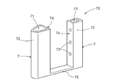
ロータ10は、さらに、外形が磁束制限孔5の内部空間に合致する形状を有する第1挿入部材7を備えている。第1挿入部材7は、内部に軸方向に延在する第1空間部71が形成された筒状部72と、筒状部72の内面と外面とを連通する連通孔73とを有する(図2〜図10等参照)。また、ロータ10は、外形が第1挿入部材7の第1空間部71に挿入可能な形状を有する第2挿入部材8を備えている(図2〜図9、図11等参照)。第2挿入部材8は、棒状部82と、第1空間部71に挿入された状態で連通孔73に対向する位置に軸方向Lに沿って形成された溝部83とを有している。
The
永久磁石21(磁力発生部材2)は部材配置孔3に配置され、第1挿入部材7は磁束制限孔5に配置され、第2挿入部材8は第1挿入部材7の第1空間部71に配置されている。第1空間部71と第2挿入部材8との隙間、及び、部材配置孔3と永久磁石21(磁力発生部材2)との隙間には、固定剤4が充填されている。永久磁石21(磁力発生部材2)は、第1挿入部材7によって部材配置孔3に位置決めされると共に、固定剤4によって部材配置孔3に固定されている。
The permanent magnet 21 (magnetic force generating member 2) is arranged in the
以下、このようなロータ10を製造する方法について説明する。図2から図4に示すようにロータ10は第1工程#1から第4工程#4の4つの工程を経て製造される。第1工程#1は、図2に示すように、部材配置孔3に永久磁石21(磁力発生部材2)を配置する工程であり、第2工程#2は、第1挿入部材7(筒状部72)を磁束制限孔5に挿入する工程である。尚、第1工程#1と第2工程#2とは、第1工程#1の次に第2工程#2が実施されてもよいし、第2工程#2の次に第1工程#1が実施されてもよいし、第1工程#1と第2工程#2とが同時期に実施されてもよい。
Hereinafter, a method of manufacturing such a
第3工程#3は、第1工程#1及び第2工程#2の後に実施される工程であり、図3に示すように、第1挿入部材7(筒状部72)の第1空間部71に流動性を有する固定剤4を注入する工程である。第4工程#4は、第3工程#3の後に実施される工程であり、図3に示すように、第2挿入部材8を第1空間部71に挿入し、図4に示すように、固定剤4を第1挿入部材7の連通孔73から流出させる工程である。
The
第1工程#1及び第2工程#2により、永久磁石21は、第1挿入部材7によって位置決めされて部材配置孔3に配置される。即ち、第1挿入部材7の部材配置孔3の側を向く面が、磁力発生部材2としての永久磁石21に対向してその移動を規制する位置規制面74となっている。尚、筒状部72の内面と外面とを連通する連通孔73は、永久磁石21と対向するように、位置規制面74に形成されていると好適である。
By the
ところで、一般的に、部材配置孔3と連通するように部材配置孔3に接して磁束制限孔5が形成されている場合には、図12に示す比較例のロータ10Bのように、永久磁石21が磁束制限孔5の側に移動しないように、磁束制限孔5と部材配置孔3との境界に規制部54Bが設けられる。しかし、本実施形態では、第1挿入部材7の位置規制面74によって永久磁石21の位置決めが可能であり、規制部54Bを設けなくてもよい。従って、磁束制限孔5は、磁束を制限するために最も適切な形状で形成可能となり、ロータ10の磁気的性能を向上させることができる。
By the way, in general, when the magnetic
第3工程#3では、図3に示すように、第1空間部71に固定剤4が注入される。本実施形態では、筒状部72は、軸方向第1側L1が閉じた有底筒状に形成されており、第1空間部71は、軸方向Lにおける一方側(ここでは軸方向第1側L1)が閉塞されている。従って、第1空間部71に注入された固定剤4は、第1空間部71に滞留する。尚、筒状部72は無底筒状に形成されていてもよく、この場合には、図3に示すように、治具や金型の基準面9によって第1空間部71の軸方向Lにおける一方側(ここでは軸方向第1側L1)が閉塞されると好適である。
In the
第4工程#4では、図3に示すように第2挿入部材8が軸方向第2側L2から軸方向第1側L1に向かって第1空間部71に挿入される。上述したように、第2挿入部材8には溝部83が形成されている。第4工程#4では、溝部83が第1挿入部材7の連通孔73に対向するように第2挿入部材8が第1空間部71に挿入されると好適である。第4工程#4において、さらに第2挿入部材8が軸方向第1側L1に移動すると、図4に示すように、第2挿入部材8が第1空間部71に貯留された固定剤4に達する。流動性を有する固定剤4は、第2挿入部材8の溝部83を通って第1挿入部材7の連通孔73に押し出されて部材配置孔3と永久磁石21(磁力発生部材2)との隙間に充填されていく。第2挿入部材8が軸方向第1側L1への移動を完了すると、図5に示すように、第1空間部71と第2挿入部材8との隙間、及び、部材配置孔3と永久磁石21(磁力発生部材2)との隙間に固定剤4が充填されてロータ10が形成される。
In the
ところで、図1等に示すように、2つの磁束制限孔5は、共に部材配置孔3に隣接している。従って、少なくとも1つの部材配置孔3に隣接して設けられる複数の磁束制限孔5にそれぞれ挿入される複数の第1挿入部材7は、同時期に挿入されると作業効率がよく、好ましい。同様に、複数の第1挿入部材7の第1空間部71にそれぞれ挿入される複数の第2挿入部材8も、同時期に挿入されると作業効率がよく、好ましい。以下、そのような第1挿入部材7及び第2挿入部材8を用いてロータ10を製造する方法について、図6から図10を参照して説明する。ロータ10は、図6から図8に示すように、上述した形態と同様に第1工程#1から第4工程#4の4つの工程を経て製造される。図9は、製造されたロータ10の一例を示している。また、図10及び図11の斜視図は、それぞれ複数の第1挿入部材7が連結された第1部材70、及び複数の第2挿入部材8が連結された第2部材80の一例を示している。
By the way, as shown in FIG. 1 and the like, the two magnetic
図10に示すように、本例では、複数の磁束制限孔5に対応する複数の第1挿入部材7が第1連結部材75により互いに連結され、第1部材70を形成している。尚、見方を変えれば、複数の磁束制限孔5に対応する複数の筒状部72が第1連結部材75により互いに連結されて、複合的な第1挿入部材部7を形成するということもできる。また、図11に示すように、本例では、複数の第1挿入部材7の第1空間部71に対応する複数の第2挿入部材8が第2連結部材85により互いに連結され、第2部材80を形成している。同様に、見方を変えれば、複数の第1挿入部材7の第1空間部71に対応する複数の棒状部82が第2連結部材85により互いに連結されて、複合的な第2挿入部材8を形成するということもできる。
As shown in FIG. 10, in the present example, the plurality of
また、ここでは、第1挿入部材7は、当該第1挿入部材7の軸方向第1側L1の端部から、ロータコア1の軸方向第1側L1の端面に沿って広がり、永久磁石21(磁力発生部材2)の軸方向第1側L1の端面を覆う第1カバー部材に連結されているということができる(図6から図9等参照。)。つまり、第1連結部材75は、第1カバー部材として機能する。また、第2挿入部材8は、当該第2挿入部材8の軸方向第2側L2の端部から、ロータコア1の軸方向第2側L2の端面に沿って広がり、永久磁石21(磁力発生部材2)の軸方向第2側L2の端面を覆う第2カバー部材に連結されているということができる(図7から図9等参照。)。つまり、第2連結部材85は、第2カバー部材として機能する。
Further, here, the
このように、第1カバー部材(第1連結部材75)及び第2カバー部材(第2連結部材85)が形成されていると、軸方向第1側L1においては第1カバー部材(第1連結部材75)によって、軸方向第2側L2においては第2カバー部材(第2連結部材85)によって、永久磁石21(磁力発生部材2)が軸方向Lに移動することを規制することができる。つまり、ロータ10の製造過程においては、固定剤4が流動性を有している状態であっても、金型等の固定装置に頼らずに、永久磁石21(磁力発生部材2)が軸方向Lに移動することを規制することができる。また、ロータ10の使用状態においても、経年変化により永久磁石21(磁力発生部材2)が軸方向Lに移動することを規制することができる。
As described above, when the first cover member (first connecting member 75) and the second cover member (second connecting member 85) are formed, the first cover member (first connecting member) is formed on the axial first side L1. The member 75) can restrict the permanent magnet 21 (magnetic force generating member 2) from moving in the axial direction L by the second cover member (second connecting member 85) on the axial second side L2. That is, in the manufacturing process of the
図2から図4を参照して上述した例と同様、第1工程#1は、図6に示すように、部材配置孔3に永久磁石21(磁力発生部材2)を配置する工程である。第1挿入部材7の筒状部72を磁束制限孔5に挿入する第2工程#2では、複数の第1挿入部材7が、それぞれ対応する磁束制限孔5に同時期に挿入される。ここでは、複数の第1挿入部材7(複数の筒状部72)が第1連結部材75により連結されて第1部材70が形成されているため、複数の磁束制限孔5に対して、複数の第1挿入部材7(複数の筒状部72)を適切に同時期に挿入させることができる。尚、上述したように、第1工程#1と第2工程#2とは、第1工程#1の次に第2工程#2が実施されてもよいし、第2工程#2の次に第1工程#1が実施されてもよいし、第1工程#1と第2工程#2とが同時期に実施されてもよい。
Similar to the example described above with reference to FIGS. 2 to 4, the
図7に示すように、第1工程#1及び第2工程#2の後に実施される第3工程#3では、第1部材70(第1挿入部材7)の筒状部72の第1空間部71に流動性を有する固定剤4が注入される。図7及び図8に示すように、第3工程#3の後に実施される第4工程#4では、複数の第2挿入部材8の棒状部82がそれぞれ対応する複数の第1空間部71に同時期に挿入され、固定剤4を複数の筒状部72の連通孔73から流出させる。ここでは、複数の第2挿入部材8(複数の棒状部82)が第2連結部材85により連結されて第2部材80が形成されているため、複数の第1空間部71に対して、複数の第2挿入部材8(複数の棒状部82)を適切に同時期に挿入させることができる。
As shown in FIG. 7, in the
本例においても、第1工程#1及び第2工程#2により、永久磁石21は、第1部材70(第1挿入部材7)の筒状部72によって位置決めされて部材配置孔3に配置される。即ち、第1部材70(第1挿入部材7)の部材配置孔3の側を向く面が、磁力発生部材2としての永久磁石21に対向してその移動を規制する位置規制面74となっている。尚、第1部材70において、それぞれの筒状部72の内面と外面とを連通する連通孔73は、永久磁石21と対向するように、位置規制面74に形成されていると好適である。本例においても、第1部材70(第1挿入部材7)の位置規制面74によって永久磁石21の位置決めが可能であり、図12に示す比較例のように、磁束制限孔5と部材配置孔3との境界に規制部54Bを設けなくてもよい。
Also in the present example, the
第3工程#3では、図7に示すように、第1空間部71に固定剤4が注入される。本例においても、筒状部72は、軸方向第1側L1が閉じた有底筒状に形成されており、第1空間部71は、軸方向Lにおける一方側(ここでは軸方向第1側L1)が閉塞されている。従って、第1空間部71に注入された固定剤4は、第1空間部71に滞留する。上述したように、筒状部72は無底筒状に形成されていてもよく、この場合には、図3及び図4に示すように、治具や金型の基準面9によって第1空間部71の軸方向Lにおける一方側(ここでは軸方向第1側L1)が閉塞されると好適である。
In the
第4工程#4では、図8に示すように第2部材80(第2挿入部材8)の複数の棒状部82が軸方向第2側L2から軸方向第1側L1に向かって複数の第1空間部71に挿入される。上述したように、第2部材80(第2挿入部材8)の棒状部82には溝部83が形成されている。第4工程#4では、溝部83が第1部材70(第1挿入部材7)の連通孔73に対向するように、第2部材80(第2挿入部材8)の棒状部82が第1空間部71に挿入されると好適である。第4工程#4において、さらに第2部材80(第2挿入部材8)の棒状部82が軸方向第1側L1に移動すると、図8に示すように、棒状部82が第1空間部71に貯留された固定剤4に達する。流動性を有する固定剤4は、棒状部82に形成された溝部83を通って第1部材70(第1挿入部材7)の連通孔73に押し出されて部材配置孔3と永久磁石21(磁力発生部材2)との隙間に充填されていく。第2部材80(第2挿入部材8)が軸方向第1側L1への移動を完了すると、図9に示すように、第1空間部71と第2挿入部材8の棒状部82との隙間、及び、部材配置孔3と永久磁石21(磁力発生部材2)との隙間に固定剤4が充填され、図9に示すようにロータ10が形成される。
In the
比較例として図12に示すロータ10Bのように、一般的に部材配置孔3に連通する磁束制限孔5Bは、固定剤4によって満たされることになる。しかし、図1から図11を参照して説明した製造方法によれば、磁束制限孔5の内部空間に合致する外形を有する第1挿入部材7と、第1挿入部材7の第1空間部71に挿入可能な形状を有する第2挿入部材8とが、磁束制限孔5に配置されて、ロータ10が形成される。このため、磁束制限孔5の内部空間において固定剤4が占める体積は大きく削減される。固定剤4の材料コストは比較的高価であり、一般的に、第1挿入部材7及び第2挿入部材8の材料コストよりも固定剤4の材料コストの方が高価である。例えば、第1挿入部材7及び第2挿入部材8が樹脂成形によって形成される場合、成型材料としての樹脂に対して固定剤4の方が、材料コストが高価である。実質的に何も固定しない磁束制限孔5に充填される固定剤4の使用量を削減することで、ロータ10の製造コストを低減させることができる。
As a comparative example, like the
また、磁束制限孔5に挿入された第1挿入部材7の第1空間部71に注入された固定剤4は、第1空間部71に挿入された第2挿入部材8によって、連通孔73を通って筒状部72の外面へと押し出される。筒状部72の外面は、磁束制限孔5及び部材配置孔3に通じており、部材配置孔3には磁力発生部材2が配置されている。従って、磁力発生部材2は、固定剤4によって部材配置孔3に固定される。磁力発生部材2と部材配置孔3との隙間に固定剤4を流入させるためには、一般的には金型等の加圧装置を利用する必要がある。しかし、図1から図11を参照して説明した製造方法によれば、第1挿入部材7の第1空間部71に第2挿入部材8を挿入することによって、そのような加圧装置を用いることなく、固定剤4によって磁力発生部材2を部材配置孔3に固定することができる。
Further, the
〔その他の実施形態〕
以下、その他の実施形態について説明する。尚、以下に説明する各実施形態の構成は、それぞれ単独で適用されるものに限られず、矛盾が生じない限り、他の実施形態の構成と組み合わせて適用することも可能である。
[Other Embodiments]
Hereinafter, other embodiments will be described. Note that the configurations of the respective embodiments described below are not limited to being applied individually, and may be applied in combination with the configurations of other embodiments as long as no contradiction occurs.
(1)図3から図5、図7〜図9、図11に示すように、上記においては、第2挿入部材8に溝部83が形成されている形態を例示して説明した。しかし、溝部は、第1挿入部材7に形成されていてもよい。つまり、溝部は、第2挿入部材8にのみ形成されていてもよいし、第1挿入部材7にのみ形成されていてもよいし、第1挿入部材7及び第2挿入部材8の双方に形成されていてもよい。
(1) As shown in FIG. 3 to FIG. 5, FIG. 7 to FIG. 9, and FIG. 11, the form in which the
第1挿入部材7に溝部が形成される場合、連通孔73は、当該溝部の底部に形成されると好適である。つまり、第1挿入部材7が磁束制限孔5に配置された状態で、第1挿入部材7に形成される溝部は永久磁石21に対向する側に開口し、当該溝部において永久磁石21に対向する側とは反対側に連通孔73が形成される。この場合、連通孔73は、位置規制面74には形成されないことになる。また、溝部が、第1挿入部材7及び第2挿入部材8の双方に形成される場合には、第1挿入部材7に形成された第1溝部の開口側と、第2挿入部材8に形成された第2溝部の開口側とが対向して、1つの流路を形成すると好適である。
When the groove portion is formed in the
(2)図6から図10に示すように、上記においては、連結対象の第1挿入部材7が、同じ部材配置孔3に連通する磁束制限孔5に挿入される部材である形態を例示した。しかし、連結対象の第1挿入部材7は、そのような形態に限らず、異なる部材配置孔3に連通する磁束制限孔5に挿入される部材であってもよい。第2挿入部材8についても同様である。
(2) As shown in FIGS. 6 to 10, in the above description, the
以下、第1挿入部材7について具体例を挙げて説明するが、第2挿入部材8についても同様である。例えば、図1に示す形態では、径方向Rの外側に向かってV字型に開いた2つの永久磁石21によって1つの磁極が構成されている。ここでは、1つの磁極に、2つの部材配置孔3が設けられ、それぞれの部材配置孔3に連通するように、2つずつ磁束制限孔5が設けられている。例えば、1つの磁極において径方向Rの外側に位置する2つの第1磁束制限孔51に挿入される第1挿入部材7が第1連結部材75によって連結されて第1部材70を構成し、1つの磁極において径方向Rの内側に位置する2つの第2磁束制限孔52に挿入される第1挿入部材7が第1連結部材75によって連結されて第1部材70を構成する形態であってもよい。当然ながら、このような形態において、1つの磁極における4つの磁束制限孔5(2つの第1磁束制限孔51と2つの第2磁束制限孔52)に挿入される4つの第1挿入部材7が第1連結部材75によって連結されて第1部材70が形成されてもよい。
Hereinafter, the
また、周方向Cに沿って径方向Rの外側の全ての第1磁束制限孔51に挿入される第1挿入部材7の全てが連結されて、第1部材70が形成されると共に、周方向Cに沿って径方向Rの内側の全ての第2磁束制限孔52に挿入される第1挿入部材7の全てが連結されて、第1部材70が形成されてもよい。さらに、周方向Cに沿って、部材配置孔3に連通する全ての磁束制限孔5に挿入される第1挿入部材7の全てが連結されて第1部材70が形成されてもよい。また、周方向Cに沿って所定の角度範囲に分割して、当該角度範囲内に含まれる磁束制限孔5に挿入される第1挿入部材7が連結されて第1部材70が構成されてもよい。例えば、90°ずつの角度範囲に分割された場合には、4つの第1部材70が用いられ、60°ずつの角度範囲に分割された場合には、6つの第1部材70が用いられる。径方向Rの内側と、外側とで独立して第1部材70が構成される場合も同様に、所定の角度範囲に分割されてもよい。
Further, all the
(3)上記においては、断面が円又は楕円の連通孔73が、軸方向Lに沿って複数並んで形成される形態を例示した。しかし、連通孔73は、軸方向Lに直交する方向に沿って複数並んで形成されてもよいし、軸方向Lに沿って複数並ぶと共に軸方向Lに直交する方向に沿って複数並んで形成されてもよい。また、連通孔73は、例えば軸方向Lに連続して開口したスリット状に形成されてもよい。また、そのようなスリット状の連通孔73が軸方向Lに直交する方向に複数列並んで形成されてもよい。
(3) In the above description, a plurality of communication holes 73 having a circular or elliptical cross section are formed side by side along the axial direction L. However, a plurality of communication holes 73 may be formed side by side along the direction orthogonal to the axial direction L, or a plurality of communication holes 73 may be formed side by side along the axial direction L and along the direction orthogonal to the axial direction L. May be done. Further, the
〔実施形態の概要〕
以下、上記において説明した回転電機用ロータの製造方法、及び回転電機用ロータ(10)の概要について簡単に説明する。
[Outline of Embodiment]
Hereinafter, an outline of the method for manufacturing the rotor for a rotary electric machine and the rotor (10) for a rotary electric machine described above will be briefly described.
1つの態様として、円筒状のロータコア(1)に磁力の発生源である永久磁石(21)又は導電体を含む磁力発生部材(2)を配置して回転電機用ロータ(10)を製造する回転電機用ロータの製造方法は、前記ロータコア(1)は、当該ロータコア(1)を軸方向(L)に貫通して前記磁力発生部材(2)が配置される部材配置孔(3)と、前記ロータコア(1)を前記軸方向(L)に貫通すると共に前記部材配置孔(3)と連通するように前記部材配置孔(3)に接して形成された磁束制限孔(5)とを有し、前記部材配置孔(3)に前記磁力発生部材(2)を配置する第1工程(#1)と、外形が前記磁束制限孔(5)の内部空間に合致する形状を有すると共に内部に前記軸方向(L)に延在する第1空間部(71)を形成する筒状部(72)を有し、前記筒状部(72)の内面と外面とを連通する連通孔(73)を有する第1挿入部材(7)を、前記磁束制限孔(5)に挿入する第2工程(#2)と、前記第1空間部(71)に流動性を有する固定剤(4)を注入する第3工程(#3)と、外形が前記第1空間部(71)に挿入可能な形状を有する第2挿入部材(8)を前記第1空間部(71)に挿入して、前記固定剤(4)を前記連通孔(73)から流出させる第4工程(#4)と、を備える。 As one aspect, a rotor for manufacturing a rotary electric machine (10) in which a permanent magnet (21) that is a source of magnetic force or a magnetic force generating member (2) including a conductor is arranged in a cylindrical rotor core (1) to manufacture a rotor (10) for a rotating electric machine. In the method of manufacturing a rotor for an electric machine, the rotor core (1) includes a member placement hole (3) in which the magnetic force generating member (2) is placed so as to penetrate the rotor core (1) in an axial direction (L), And a magnetic flux limiting hole (5) formed in contact with the member disposing hole (3) so as to penetrate the rotor core (1) in the axial direction (L) and communicate with the member disposing hole (3). A first step (#1) of arranging the magnetic force generation member (2) in the member arrangement hole (3), and an external shape having a shape matching the internal space of the magnetic flux restriction hole (5) It has a tubular portion (72) forming a first space portion (71) extending in the axial direction (L), and a communication hole (73) for communicating an inner surface and an outer surface of the tubular portion (72). The second step (#2) of inserting the first insertion member (7) having the fluid into the magnetic flux limiting hole (5), and injecting the fluid fixative (4) into the first space portion (71). In the third step (#3), a second insertion member (8) having an outer shape that can be inserted into the first space portion (71) is inserted into the first space portion (71), and the fixative is added. A fourth step (#4) of letting (4) flow out from the communication hole (73).
一般的に、部材配置孔(3)に流動性を有する固定材(4)を注入すると、当該部材配置孔(3)に連通する磁束制限孔(5)は、固定剤(4)によって満たされることになる。しかし、この製造方法によれば、磁束制限孔(5)の内部空間に合致する外形を有する第1挿入部材(7)と、第1挿入部材(7)の第1空間部(71)に挿入可能な形状を有する第2挿入部材(8)とが、磁束制限孔(5)に配置される。このため、磁束制限孔(5)の内部空間において固定剤(4)が占める体積は大きく削減される。つまり、一般的に成型材料よりも高価な固定剤(4)の使用量を削減することができて、製造コストを低減させることができる。また、磁束制限孔(5)に挿入された第1挿入部材(7)の第1空間部(71)に注入された固定剤(4)は、第1空間部(71)に挿入された第2挿入部材(8)によって、連通孔(73)を通って筒状部(72)の外面へと押し出される。筒状部(72)の外面は、磁束制限孔(5)及び部材配置孔(3)に通じており、部材配置孔(3)には磁力発生部材(2)が配置されている。従って、磁力発生部材(2)は、固定剤(4)によって部材配置孔(3)に固定される。磁力発生部材(2)と部材配置孔(3)との隙間に固定剤(4)を流入させるためには、一般的には金型等の加圧装置を利用する必要がある。しかし、本製造方法によれば、第1挿入部材(7)の第1空間部(71)に第2挿入部材(8)を挿入することによって、そのような加圧装置を用いることなく、固定剤(4)によって磁力発生部材(2)を部材配置孔(3)に固定することができる。このように、本製造方法によれば、低コストでロータコア(1)に磁力発生部材(2)を適切に固定して回転電機用ロータ(10)を製造する技術を提供することができる。 Generally, when the fixing material (4) having fluidity is injected into the member arrangement hole (3), the magnetic flux limiting hole (5) communicating with the member arrangement hole (3) is filled with the fixing agent (4). It will be. However, according to this manufacturing method, the first insertion member (7) having an outer shape matching the internal space of the magnetic flux limiting hole (5) and the first space member (71) of the first insertion member (7) are inserted. A second insert member (8) having a possible shape is arranged in the magnetic flux limiting hole (5). Therefore, the volume occupied by the fixative (4) in the internal space of the magnetic flux limiting hole (5) is greatly reduced. That is, it is possible to reduce the amount of the fixing agent (4) that is generally more expensive than the molding material, and it is possible to reduce the manufacturing cost. In addition, the fixative (4) injected into the first space portion (71) of the first insertion member (7) inserted into the magnetic flux limiting hole (5) is inserted into the first space portion (71). It is pushed out to the outer surface of the tubular portion (72) through the communication hole (73) by the 2 insertion member (8). The outer surface of the tubular portion (72) communicates with the magnetic flux limiting hole (5) and the member placement hole (3), and the magnetic force generation member (2) is placed in the member placement hole (3). Therefore, the magnetic force generating member (2) is fixed to the member arrangement hole (3) by the fixing agent (4). In order to make the fixing agent (4) flow into the gap between the magnetic force generating member (2) and the member arrangement hole (3), it is generally necessary to use a pressurizing device such as a mold. However, according to the present manufacturing method, the second insertion member (8) is inserted into the first space portion (71) of the first insertion member (7) to fix the second insertion member (7) without using such a pressurizing device. The magnetic force generating member (2) can be fixed to the member arrangement hole (3) by the agent (4). As described above, according to the present manufacturing method, it is possible to provide a technique for manufacturing the rotor (10) for a rotary electric machine by appropriately fixing the magnetic force generation member (2) to the rotor core (1) at low cost.
ここで、前記第1挿入部材(7)の前記第1空間部(71)は、前記軸方向(L)における一方側が閉塞されていると好適である。 Here, it is preferable that the first space portion (71) of the first insertion member (7) is closed on one side in the axial direction (L).
第1空間部(71)の軸方向(L)における一方側が閉塞されていると、第1空間部(71)に注入される固定剤(4)を第1空間部(71)に貯留させることができて好ましい。尚、この閉塞とは、例えば筒状部(72)が有底筒状に形成されて、第1挿入部材(7)自体によって第1空間部(71)が閉塞されるような形態であってもよいし、無底筒状の筒状部(72)の軸方向(L)の一端側が製造設備における基準面(9)等によって閉塞される形態であってもよい。 When one side in the axial direction (L) of the first space portion (71) is closed, the fixative (4) injected into the first space portion (71) is stored in the first space portion (71). Is preferred, which is preferable. It should be noted that this closing is a form in which, for example, the tubular portion (72) is formed in a tubular shape with a bottom, and the first space portion (71) is closed by the first insertion member (7) itself. Alternatively, one end side of the bottomless tubular portion (72) in the axial direction (L) may be closed by the reference surface (9) or the like in the manufacturing facility.
また、複数の前記磁束制限孔(5)に対応する複数の前記第1挿入部材(7)が第1連結部材(75)により互いに連結されており、前記第2工程(#2)では、複数の前記第1挿入部材(7)をそれぞれ対応する前記磁束制限孔(5)に同時期に挿入すると好適である。 Further, the plurality of first insertion members (7) corresponding to the plurality of magnetic flux limiting holes (5) are connected to each other by a first connecting member (75), and in the second step (#2), a plurality of It is preferable that the first insertion members (7) are inserted into the corresponding magnetic flux limiting holes (5) at the same time.
一般的に、ロータコア(1)には、複数の部材配置孔(3)が形成され、複数の磁束制限孔(5)が形成されている。このような場合に、磁束制限孔(5)ごとに第1挿入部材(7)を配置していくと、工数が増加して製造コストが上昇する可能性がある。本製造方法のように、複数の磁束制限孔(5)に対応する複数の第1挿入部材(7)が第1連結部材(75)によって連結されており、複数の磁束制限孔(5)に対して同時期に複数の第1挿入部材(7)が挿入されると、工数を削減することができて、製造コストを低減することができる。ところで、1つの部材配置孔(3)に対して複数の磁束制限孔(5)が連通するように設けられている場合があるが、連結対象の第1挿入部材(7)は、同じ部材配置孔(3)に連通する磁束制限孔(5)に挿入される部材に限らず、それぞれ異なる部材配置孔(3)に連通する磁束制限孔(5)に挿入される部材であってもよい。 Generally, the rotor core (1) has a plurality of member placement holes (3) and a plurality of magnetic flux limiting holes (5). In such a case, if the first insertion member (7) is arranged for each magnetic flux limiting hole (5), the number of steps may increase and the manufacturing cost may increase. As in the present manufacturing method, the plurality of first insertion members (7) corresponding to the plurality of magnetic flux limiting holes (5) are connected by the first connecting member (75), and the plurality of magnetic flux limiting holes (5) are connected to the plurality of magnetic flux limiting holes (5). On the other hand, if a plurality of first insertion members (7) are inserted at the same time, the number of steps can be reduced and the manufacturing cost can be reduced. By the way, a plurality of magnetic flux limiting holes (5) may be provided so as to communicate with one member arrangement hole (3), but the first insertion member (7) to be connected has the same member arrangement. The member is not limited to the member inserted into the magnetic flux limiting hole (5) communicating with the hole (3), but may be the member inserted into the magnetic flux limiting hole (5) communicating with the different member arrangement holes (3).
また、複数の前記第1挿入部材(7)に対応する複数の前記第2挿入部材(8)が第2連結部材(85)により互いに連結されており、前記第4工程(#4)では、複数の前記第2挿入部材(8)をそれぞれ対応する前記第1空間部(71)に同時期に挿入すると好適である。 Further, the plurality of second insertion members (8) corresponding to the plurality of first insertion members (7) are connected to each other by the second connection member (85), and in the fourth step (#4), It is preferable to insert a plurality of the second insertion members (8) into the corresponding first space portions (71) at the same time.
一般的に、ロータコア(1)には、複数の部材配置孔(3)が形成され、複数の磁束制限孔(5)が形成されており、それぞれの磁束制限孔(5)には第1挿入部材(7)が配置される。ここで、第1挿入部材(7)の第1空間部(71)ごとに第2挿入部材(8)を挿入していくと、工数が増加して製造コストが上昇する可能性がある。本製造方法のように、複数の第1空間部(71)に対応する複数の第2挿入部材(8)が第2連結部材(85)によって連結されており、複数の第1空間部(71)に対して同時期に複数の第2挿入部材(8)が挿入されると、工数を削減することができて、製造コストを低減することができる。ところで、1つの部材配置孔(3)に対して複数の磁束制限孔(5)が連通するように設けられており、それぞれに第1挿入部材(7)が配置されている場合がある。連結対象の第2挿入部材(8)は、同じ部材配置孔(3)に連通する磁束制限孔(5)に配置された第1挿入部材(7)の第1空間部(71)に挿入される部材に限らない。それぞれ異なる部材配置孔(3)に連通する磁束制限孔(5)に配置された第1挿入部材(7)の第1空間部(71)に挿入される部材が、連結対象であってもよい。 Generally, a rotor core (1) is formed with a plurality of member placement holes (3) and a plurality of magnetic flux limiting holes (5), and each magnetic flux limiting hole (5) has a first insertion. A member (7) is arranged. Here, if the second insertion member (8) is inserted into each of the first space portions (71) of the first insertion member (7), the number of steps may increase and the manufacturing cost may increase. As in the present manufacturing method, the plurality of second insertion members (8) corresponding to the plurality of first space portions (71) are connected by the second connecting member (85), and the plurality of first space portions (71) are connected. ), a plurality of second insertion members (8) are inserted at the same time, the number of steps can be reduced, and the manufacturing cost can be reduced. By the way, there are cases where a plurality of magnetic flux limiting holes (5) are provided so as to communicate with one member arrangement hole (3), and the first insertion member (7) is arranged in each of them. The second insertion member (8) to be connected is inserted into the first space portion (71) of the first insertion member (7) arranged in the magnetic flux limiting hole (5) communicating with the same member arrangement hole (3). The material is not limited to A member to be inserted into the first space portion (71) of the first insertion member (7) arranged in the magnetic flux limiting hole (5) communicating with the different member arrangement holes (3) may be a connection target. ..
また、前記軸方向(L)の一方側を軸方向第1側(L1)とし、前記軸方向(L)の他方側を軸方向第2側(L2)として、前記第1挿入部材(7)は、当該第1挿入部材(7)の前記軸方向第1側(L1)の端部から、前記ロータコア(1)の前記軸方向第1側(L1)の端面に沿って広がり、前記磁力発生部材(2)の前記軸方向第1側(L1)の端面を覆う第1カバー部材(75)に連結され、前記第2挿入部材(8)は、当該第2挿入部材(8)の前記軸方向第2側(L2)の端部から、前記ロータコア(1)の前記軸方向第2側(L2)の端面に沿って広がり、前記磁力発生部材(2)の前記軸方向第2側(L2)の端面を覆う第2カバー部材(85)に連結されていると好適である。 Further, one side of the axial direction (L) is referred to as an axial first side (L1) and the other side of the axial direction (L) is referred to as an axial second side (L2), and the first insertion member (7) is provided. Spreads from the end of the first insertion member (7) on the first axial side (L1) along the end surface of the rotor core (1) on the first axial side (L1) to generate the magnetic force. The second insert member (8) is connected to the first cover member (75) that covers the end surface of the member (2) on the first axial side (L1), and the second insert member (8) is the shaft of the second insert member (8). From the end on the direction second side (L2) along the end surface on the axial second side (L2) of the rotor core (1), and extends on the axial second side (L2) of the magnetic force generating member (2). ) Is preferably connected to the second cover member (85) that covers the end face of the above.
例えば、1つの部材配置孔(3)を挟むように複数の磁束制限孔(5)が設けられている場合がある。上記のように、第1カバー部材(75)及び第2カバー部材(85)が形成されていると、軸方向第1側(L1)においては第1カバー部材(75)によって、軸方向第2側(L2)においては第2カバー部材(85)によって、磁力発生部材(2)が軸方向(L)に移動することを規制することができる。つまり、回転電機用ロータ(10)の製造過程においては、固定剤(4)が流動性を有している状態であっても磁力発生部材(2)が軸方向(L)に移動することを規制することができる。また、回転電機用ロータ(10)の使用状態においても、経年変化等により磁力発生部材(2)が軸方向(L)に移動することを規制することができる。 For example, a plurality of magnetic flux limiting holes (5) may be provided so as to sandwich one member arrangement hole (3). As described above, when the first cover member (75) and the second cover member (85) are formed, the first cover member (75) allows the second axial direction second side (L1) to be formed. On the side (L2), the second cover member (85) can restrict the magnetic force generating member (2) from moving in the axial direction (L). That is, in the manufacturing process of the rotor (10) for a rotating electric machine, the magnetic force generation member (2) is prevented from moving in the axial direction (L) even when the fixative (4) has fluidity. Can be regulated. Further, even when the rotor (10) for a rotary electric machine is in use, it is possible to prevent the magnetic force generation member (2) from moving in the axial direction (L) due to aging or the like.
また、前記第1挿入部材(7)の前記部材配置孔(3)の側を向く面が、前記磁力発生部材(2)に対向して前記磁力発生部材(2)の移動を規制する位置規制面(74)となっていると好適である。 Further, a position regulation in which a surface of the first insertion member (7) facing the member placement hole (3) faces the magnetic force generation member (2) and regulates the movement of the magnetic force generation member (2). The surface (74) is preferable.
部材配置孔(3)に連通するように磁束制限孔(5)が形成されている場合、磁力発生部材(2)が磁束制限孔(5)の側に移動することを規制するために、磁束制限孔(5)と部材配置孔(3)との境界に規制部(54B)が形成される場合がある。しかし、第1挿入部材(7)が位置規制面(74)を有すると、そのような規制部(54B)を設ける必要がなくなる。磁束制限孔(5)は、磁束を制限するために最も適切な形状で形成可能となり、回転電機用ロータ(10)の磁気的性能を向上させることができる。 When the magnetic flux limiting hole (5) is formed so as to communicate with the member arrangement hole (3), the magnetic flux is generated in order to prevent the magnetic force generating member (2) from moving toward the magnetic flux limiting hole (5). A regulation part (54B) may be formed at the boundary between the restriction hole (5) and the member arrangement hole (3). However, when the first insertion member (7) has the position regulating surface (74), it is not necessary to provide such a regulating portion (54B). The magnetic flux limiting hole (5) can be formed in the most suitable shape for limiting the magnetic flux, and the magnetic performance of the rotor (10) for a rotary electric machine can be improved.
また、前記第1挿入部材(7)における前記連通孔(73)に対応する位置、及び前記第2挿入部材(8)における前記連通孔(73)に対応する位置、の少なくとも一方の位置に、前記軸方向(L)に延在する溝部(83)が形成されていると好適である。 Further, at least one of a position corresponding to the communication hole (73) in the first insertion member (7) and a position corresponding to the communication hole (73) in the second insertion member (8), It is preferable that a groove (83) extending in the axial direction (L) is formed.
上述したように、第1挿入部材(7)の第1空間部(71)に第2挿入部材(8)が挿入されることにより、第1空間部(71)に貯留された固定剤(4)が連通部(73)を通って第1空間部(71)の外部に流出する。ここで、第1空間部(71)を形成する筒状部(72)の内面と、第2挿入部材(8)の外面との隙間が筒状部(72)の内面の全周に亘って均等であると、固定剤(4)を移動させる圧力も均等となり、第1空間部(71)から連通部(73)への固定剤(4)の流れが分散する可能性がある。上述したように溝部(83)が形成されると、筒状部(72)の内面の周方向において溝部(83)に相当する位置では、隙間が広がり、固定剤(4)を移動させるための圧力も小さくなる。このため、固定剤(4)は溝部(83)を通って適切に連通部(73)に導かれ、連通部(73)から第1空間部(71)の外部に流出することができる。 As described above, the fixing agent (4) stored in the first space portion (71) is inserted by inserting the second insertion member (8) into the first space portion (71) of the first insertion member (7). ) Flows out of the first space portion (71) through the communication portion (73). Here, the gap between the inner surface of the tubular portion (72) forming the first space portion (71) and the outer surface of the second insertion member (8) is provided over the entire circumference of the inner surface of the tubular portion (72). If it is uniform, the pressure for moving the fixative (4) will also be uniform, and the flow of the fixative (4) from the first space portion (71) to the communication portion (73) may be dispersed. When the groove portion (83) is formed as described above, the gap widens at the position corresponding to the groove portion (83) in the circumferential direction of the inner surface of the tubular portion (72), and the fixative (4) is moved. The pressure also decreases. For this reason, the fixative (4) can be appropriately guided to the communication part (73) through the groove part (83) and flow out of the communication part (73) to the outside of the first space part (71).
上述した回転電機用ロータの製造方法の技術的特徴は、当該製造方法を用いて製造された回転電機用ロータ(10)にも適用可能である。以下に、その代表的な態様を例示する。尚、以下において例示に漏れていても、回転電機用ロータの製造方法の好適な態様として上記において例示した種々の付加的特徴を、回転電機用ロータ(10)に組み込むことが可能である。そして、そのような回転電機用ロータ(10)は、回転電機用ロータの製造方法の付加的特徴に対応する作用効果も奏することができる。 The technical features of the method for manufacturing a rotor for a rotary electric machine described above are also applicable to the rotor (10) for a rotary electric machine manufactured by using the manufacturing method. The typical mode is illustrated below. In addition, even if it is not shown in the example below, it is possible to incorporate the various additional features exemplified above as the preferred embodiments of the method for manufacturing a rotor for a rotary electric machine in the rotor (10) for a rotary electric machine. And such a rotor for rotary electric machines (10) can also exhibit the operation effect corresponding to the additional characteristic of the manufacturing method of the rotor for rotary electric machines.
1つの態様として、円筒状のロータコア(1)に磁力の発生源である永久磁石(21)又は導電体を含む磁力発生部材(2)が配置された回転電機用ロータ(10)は、前記ロータコア(1)は、当該ロータコア(1)を軸方向(L)に貫通して前記磁力発生部材(2)が配置される部材配置孔(3)と、前記ロータコア(1)を前記軸方向(L)に貫通すると共に前記部材配置孔(3)と連通するように前記部材配置孔(3)に接して形成された磁束制限孔(5)とを有し、さらに、外形が前記磁束制限孔(5)の内部空間に合致する形状を有すると共に、内部に前記軸方向(L)に延在する第1空間部(71)が形成された筒状部(72)と、前記筒状部(72)の内面と外面とを連通する連通孔(73)とを有する第1挿入部材(7)と、外形が前記第1空間部(71)に挿入可能な形状を有する第2挿入部材(8)と、を備え、前記部材配置孔(3)に前記磁力発生部材(2)が配置され、前記磁束制限孔(5)に前記第1挿入部材(7)が配置され、前記第1挿入部材(7)の前記第1空間部(71)に前記第2挿入部材(8)が配置され、前記第1空間部(71)と前記第2挿入部材(8)との隙間、及び、前記部材配置孔(3)と前記磁力発生部材(2)との隙間に固定剤(4)が充填されている。 As one aspect, the rotor (10) for a rotating electric machine, wherein the magnetic force generating member (2) including a permanent magnet (21) that is a magnetic force generation source or a conductor is arranged in a cylindrical rotor core (1), (1) is a member arranging hole (3) in which the magnetic force generating member (2) is arranged so as to penetrate the rotor core (1) in the axial direction (L), and the rotor core (1) in the axial direction (L). ) And a magnetic flux limiting hole (5) formed in contact with the member arranging hole (3) so as to communicate with the member arranging hole (3) and further has an outer shape of the magnetic flux limiting hole (5). 5) A tubular portion (72) having a shape matching the internal space of (5) and having therein a first space portion (71) extending in the axial direction (L), and the tubular portion (72). ), and a second insertion member (8) having a communication hole (73) for communicating the inner surface and the outer surface with each other, and an outer shape having a shape insertable into the first space portion (71). And the magnetic force generation member (2) is arranged in the member arrangement hole (3), the first insertion member (7) is arranged in the magnetic flux limiting hole (5), and the first insertion member ( 7) The second insertion member (8) is arranged in the first space portion (71), the gap between the first space portion (71) and the second insertion member (8), and the member arrangement. A fixing agent (4) is filled in a gap between the hole (3) and the magnetic force generating member (2).
一般的に、部材配置孔(3)と磁力発生部材(2)との隙間に固定剤(4)が充填されていると、部材配置孔(3)に連通する磁束制限孔(5)にも固定剤が流出して、磁束制限孔(5)も固定剤(4)によって満たされていることになる。しかし、この構成によれば、磁束制限孔(5)の内部空間に合致する外形を有する第1挿入部材(7)と、第1挿入部材(7)の第1空間部(71)に挿入可能な形状を有する第2挿入部材(8)とが、磁束制限孔(5)に配置されている。このため、磁束制限孔(5)の内部空間において固定剤(4)が占める体積は大きく削減される。つまり、一般的に成型材料よりも高価な固定剤(4)の使用量を削減することができて、回転電機用ロータ(10)の製造コストを低減させることができる。また、筒状部(72)の内面に形成され、第2挿入部材(8)が配置される第1空間部(71)と、磁力発生部材(2)が配置される部材配置孔(3)に連通する筒状部(72)の外面とは、連通孔(73)によって連通されている。そして、固定剤(4)は、第1空間部(71)と第2挿入部材(8)との隙間、及び、部材配置孔(3)と磁力発生部材(2)との隙間に充填されている。従って、固定剤(4)によって磁力発生部材(2)を部材配置孔(3)に固定することができる。このように、このように、本構成によれば、低コストで製造でき、ロータコア(1)に磁力発生部材(2)が適切に固定された回転電機用ロータ(10)を実現することができる。 Generally, when the gap between the member disposing hole (3) and the magnetic force generating member (2) is filled with the fixative (4), the magnetic flux limiting hole (5) communicating with the member disposing hole (3) is also formed. The fixative flows out, and the magnetic flux limiting holes (5) are also filled with the fixative (4). However, according to this structure, it is possible to insert the first insertion member (7) having an outer shape matching the internal space of the magnetic flux restriction hole (5) and the first space portion (71) of the first insertion member (7). The second insertion member (8) having a different shape is arranged in the magnetic flux limiting hole (5). Therefore, the volume occupied by the fixative (4) in the internal space of the magnetic flux limiting hole (5) is greatly reduced. That is, it is possible to reduce the amount of the fixing agent (4) used, which is generally more expensive than the molding material, and to reduce the manufacturing cost of the rotor (10) for a rotary electric machine. Further, a first space portion (71) formed on the inner surface of the tubular portion (72) in which the second insertion member (8) is arranged, and a member arrangement hole (3) in which the magnetic force generating member (2) is arranged. The outer surface of the tubular portion (72) communicating with the above is communicated with the communication hole (73). Then, the fixative (4) is filled in the gap between the first space portion (71) and the second insertion member (8) and the gap between the member arrangement hole (3) and the magnetic force generation member (2). There is. Therefore, the magnetic force generating member (2) can be fixed to the member arrangement hole (3) by the fixing agent (4). As described above, according to this configuration, the rotor (10) for a rotary electric machine which can be manufactured at low cost and in which the magnetic force generating member (2) is appropriately fixed to the rotor core (1) can be realized. ..
また、1つの態様として、回転電機用ロータ(10)は、複数の前記磁束制限孔(5)に対応する複数の前記第1挿入部材(7)を前記ロータコア(1)の外部で互いに連結する第1連結部材(75)を備えると好適である。 Further, as one aspect, the rotor (10) for a rotary electric machine connects the plurality of first insertion members (7) corresponding to the plurality of magnetic flux limiting holes (5) to each other outside the rotor core (1). It is preferable to include the first connecting member (75).
一般的に、ロータコア(1)には、複数の部材配置孔(3)が形成され、複数の磁束制限孔(5)が形成されている。本構成のように、複数の磁束制限孔(5)に対応する複数の第1挿入部材(7)が第1連結部材(75)によって連結されていると、部品総数を削減することができ、部品コストや製造コストを低減することができる。尚、1つの部材配置孔(3)に対して複数の磁束制限孔(5)が連通するように設けられている場合があるが、連結対象の第1挿入部材(7)は、同じ部材配置孔(3)に連通する磁束制限孔(5)に挿入される部材に限らず、それぞれ異なる部材配置孔(3)に連通する磁束制限孔(5)に挿入される部材であってもよい。 Generally, the rotor core (1) has a plurality of member placement holes (3) and a plurality of magnetic flux limiting holes (5). When the plurality of first insertion members (7) corresponding to the plurality of magnetic flux limiting holes (5) are connected by the first connecting member (75) as in this configuration, the total number of parts can be reduced, It is possible to reduce component costs and manufacturing costs. In addition, although a plurality of magnetic flux limiting holes (5) may be provided so as to communicate with one member arrangement hole (3), the first insertion member (7) to be connected has the same member arrangement. The member is not limited to the member inserted into the magnetic flux limiting hole (5) communicating with the hole (3), but may be the member inserted into the magnetic flux limiting hole (5) communicating with the different member arrangement holes (3).
また、1つの態様として、回転電機用ロータ(10)は、複数の前記第1挿入部材(7)に対応する複数の前記第2挿入部材(8)を前記ロータコア(1)の外部で互いに連結する第2連結部材(85)を備えると好適である。 Moreover, as one aspect, a rotor (10) for a rotary electric machine connects a plurality of the second insert members (8) corresponding to the plurality of the first insert members (7) to each other outside the rotor core (1). It is preferable to include a second connecting member (85) that does.
一般的に、ロータコア(1)には、複数の部材配置孔(3)が形成され、複数の磁束制限孔(5)が形成されており、それぞれの磁束制限孔(5)には第1挿入部材(7)が配置される。本構成のように、複数の第1挿入部材(7)の第1空間部(71)に対応する複数の第2挿入部材(8)が第2連結部材(85)によって連結されていると、部品総数を削減することができ、部品コストや製造コストを低減することができる。ところで、1つの部材配置孔(3)に対して複数の磁束制限孔(5)が連通するように設けられており、それぞれに第1挿入部材(7)が配置されている場合がある。連結対象の第2挿入部材(8)は、同じ部材配置孔(3)に連通する磁束制限孔(5)に配置された第1挿入部材(7)の第1空間部(71)に挿入される部材に限らない。それぞれ異なる部材配置孔(3)に連通する磁束制限孔(5)に配置された第1挿入部材(7)の第1空間部(71)に挿入される部材が、連結対象であってもよい。 Generally, the rotor core (1) is formed with a plurality of member placement holes (3) and a plurality of magnetic flux limiting holes (5), and each magnetic flux limiting hole (5) has a first insertion hole. A member (7) is arranged. When the plurality of second insertion members (8) corresponding to the first space portions (71) of the plurality of first insertion members (7) are connected by the second connecting member (85) as in this configuration, The total number of parts can be reduced, and the parts cost and manufacturing cost can be reduced. By the way, there are cases where a plurality of magnetic flux limiting holes (5) are provided so as to communicate with one member arrangement hole (3), and the first insertion member (7) is arranged in each of them. The second insertion member (8) to be connected is inserted into the first space portion (71) of the first insertion member (7) arranged in the magnetic flux limiting hole (5) communicating with the same member arrangement hole (3). The material is not limited to A member to be inserted into the first space portion (71) of the first insertion member (7) arranged in the magnetic flux limiting hole (5) communicating with the different member arrangement holes (3) may be a connection target. ..
また、1つの態様として、回転電機用ロータ(10)は、前記軸方向(L)の一方側を軸方向第1側(L1)とし、前記軸方向(L)の他方側を軸方向第2側(L2)として、前記第1挿入部材(7)の前記軸方向第1側(L1)の端部から、前記ロータコア(1)の前記軸方向第1側(L1)の端面に沿って広がり、前記磁力発生部材(2)の前記軸方向第1側(L1)の端面を覆う第1カバー部材(75)と、前記第2挿入部材(8)の前記軸方向第2側(L2)の端部から、前記ロータコア(1)の前記軸方向第2側(L2)の端面に沿って広がり、前記磁力発生部材(2)の前記軸方向第2側(L2)の端面を覆う第2カバー部材(85)と、を備えると好適である。 As one aspect, the rotor (10) for a rotary electric machine has one side in the axial direction (L) as an axial first side (L1) and the other side in the axial direction (L) as an axial second side. As the side (L2), it extends from the end portion of the first insertion member (7) on the first axial side (L1) along the end surface of the rotor core (1) on the first axial side (L1). A first cover member (75) covering the end surface of the magnetic force generating member (2) on the first axial side (L1) and a second axial side (L2) of the second insertion member (8). A second cover that extends from the end portion along the end surface of the rotor core (1) on the second axial side (L2) and covers the end surface of the magnetic force generating member (2) on the second axial side (L2). And a member (85).
例えば、1つの部材配置孔(3)を挟むように複数の磁束制限孔(5)が設けられている場合がある。本構成のように、第1カバー部材(75)及び第2カバー部材(85)が形成されていると、軸方向第1側(L1)においては第1カバー部材(75)によって、軸方向第2側(L2)においては第2カバー部材(85)によって、磁力発生部材(2)が軸方向(L)に移動することを規制することができる。これにより、例えば、経年変化等により磁力発生部材(2)が軸方向(L)に移動することを規制することができる。一般的に、そのように磁力発生部材(2)が軸方向(L)に移動することを抑制するために、ロータコア(1)の軸方向(L)の端部にエンドプレート等と称される部材が配置される場合がある。本構成によれば、そのような部材を設けることなく磁力発生部材(2)の移動を規制して回転電機用ロータ(10)を構成することができる。 For example, a plurality of magnetic flux limiting holes (5) may be provided so as to sandwich one member arrangement hole (3). When the first cover member (75) and the second cover member (85) are formed as in this configuration, the first cover member (75) allows the first cover member (75) and the second cover member (85) to move in the axial direction. On the second side (L2), the second cover member (85) can restrict the magnetic force generating member (2) from moving in the axial direction (L). Thereby, for example, it is possible to restrict the magnetic force generating member (2) from moving in the axial direction (L) due to aging or the like. Generally, in order to prevent the magnetic force generating member (2) from moving in the axial direction (L), an end plate or the like is called at the end of the rotor core (1) in the axial direction (L). The member may be arranged. According to this configuration, it is possible to configure the rotor (10) for a rotary electric machine by restricting the movement of the magnetic force generation member (2) without providing such a member.
また、1つの態様として、回転電機用ロータ(10)は、前記第1挿入部材(7)が、前記磁力発生部材(2)に対向して前記磁力発生部材(2)の移動を規制する位置規制面(74)を備えていると好適である。 Moreover, as one aspect, in the rotor (10) for a rotating electric machine, the first insertion member (7) faces the magnetic force generating member (2) and restricts the movement of the magnetic force generating member (2). It is preferable to have the regulation surface (74).
部材配置孔(3)に連通するように磁束制限孔(5)が形成されている場合、磁力発生部材(2)が磁束制限孔(5)の側に移動することを規制するために、磁束制限孔(5)と部材配置孔(3)との境界に規制部(54B)が形成される場合がある。しかし、第1挿入部材(7)が位置規制面(74)を有すると、そのような規制部(54B)を設ける必要がなくなる。従って、磁束制限孔(5)は、磁束を制限するために最も適切な形状で形成可能となり、回転電機用ロータ(10)の磁気的性能を向上させることができる。 When the magnetic flux limiting hole (5) is formed so as to communicate with the member arrangement hole (3), the magnetic flux is generated in order to prevent the magnetic force generating member (2) from moving toward the magnetic flux limiting hole (5). A regulation part (54B) may be formed at the boundary between the restriction hole (5) and the member arrangement hole (3). However, when the first insertion member (7) has the position regulating surface (74), it is not necessary to provide such a regulating portion (54B). Therefore, the magnetic flux limiting hole (5) can be formed in the most suitable shape for limiting the magnetic flux, and the magnetic performance of the rotor (10) for a rotary electric machine can be improved.
1 ロータコア
2 磁力発生部材
3 部材配置孔
4 固定剤
5 磁束制限孔
7 第1挿入部材
8 第2挿入部材
10 ロータ(回転電機用ロータ)
21 永久磁石(磁力発生部材)
71 第1空間部
72 筒状部
73 連通孔
74 位置規制面
75 第1連結部材(第1カバー部材)
83 溝部
85 第2連結部材(第2カバー部材)
L 軸方向
L1 軸方向第1側
L2 軸方向第2側
#1 第1工程
#2 第2工程
#3 第3工程
#4 第4工程
1
21 Permanent magnet (Magnetic force generating member)
71
83
L axis direction L1 axis direction first side L2 axis direction
Claims (12)
前記ロータコアは、当該ロータコアを軸方向に貫通して前記磁力発生部材が配置される部材配置孔と、前記ロータコアを前記軸方向に貫通すると共に前記部材配置孔と連通するように前記部材配置孔に接して形成された磁束制限孔とを有し、
前記部材配置孔に前記磁力発生部材を配置する第1工程と、
外形が前記磁束制限孔の内部空間に合致する形状を有すると共に内部に前記軸方向に延在する第1空間部を形成する筒状部を有し、前記筒状部の内面と外面とを連通する連通孔を有する第1挿入部材を、前記磁束制限孔に挿入する第2工程と、
前記第1空間部に流動性を有する固定剤を注入する第3工程と、
外形が前記第1空間部に挿入可能な形状を有する第2挿入部材を前記第1空間部に挿入して、前記固定剤を前記連通孔から流出させる第4工程と、
を備える回転電機用ロータの製造方法。 A method for manufacturing a rotor for a rotary electric machine, wherein a magnetic force generating member including a permanent magnet or a conductor that is a magnetic force generation source is arranged in a cylindrical rotor core to manufacture a rotor for a rotary electric machine.
The rotor core has a member placement hole that axially penetrates the rotor core and in which the magnetic force generating member is located, and a member placement hole that penetrates the rotor core in the axial direction and communicates with the member placement hole. Has a magnetic flux limiting hole formed in contact with,
A first step of disposing the magnetic force generating member in the member disposing hole,
The external shape has a shape that matches the internal space of the magnetic flux limiting hole, and has a tubular portion that forms a first space portion that extends in the axial direction, and communicates the inner surface and the outer surface of the tubular portion. A second step of inserting the first insertion member having a communication hole into the magnetic flux limiting hole;
A third step of injecting a fluid fixative into the first space,
A fourth step of inserting a second insertion member having an outer shape that can be inserted into the first space portion into the first space portion, and allowing the fixative to flow out from the communication hole;
A method for manufacturing a rotor for a rotary electric machine, comprising:
前記第2工程では、複数の前記第1挿入部材をそれぞれ対応する前記磁束制限孔に同時期に挿入する、請求項1又は2に記載の回転電機用ロータの製造方法。 A plurality of the first insertion members corresponding to the plurality of magnetic flux limiting holes are connected to each other by a first connecting member,
The method for manufacturing a rotor for a rotary electric machine according to claim 1, wherein in the second step, the plurality of first insertion members are inserted into the corresponding magnetic flux limiting holes at the same time.
前記第4工程では、複数の前記第2挿入部材をそれぞれ対応する前記第1空間部に同時期に挿入する、請求項1から3の何れか一項に記載の回転電機用ロータの製造方法。 A plurality of the second insert members corresponding to the plurality of the first insert members are connected to each other by a second connecting member,
The said 4th process WHEREIN: The manufacturing method of the rotor for rotary electric machines as described in any one of Claim 1 to 3 which inserts a plurality of said 2nd insertion member in the said 1st space part respectively corresponding at the same time.
前記第1挿入部材は、当該第1挿入部材の前記軸方向第1側の端部から、前記ロータコアの前記軸方向第1側の端面に沿って広がり、前記磁力発生部材の前記軸方向第1側の端面を覆う第1カバー部材に連結され、
前記第2挿入部材は、当該第2挿入部材の前記軸方向第2側の端部から、前記ロータコアの前記軸方向第2側の端面に沿って広がり、前記磁力発生部材の前記軸方向第2側の端面を覆う第2カバー部材に連結されている請求項1から4の何れか一項に記載の回転電機用ロータの製造方法。 One side of the axial direction is an axial first side, the other side of the axial direction is an axial second side,
The first insertion member spreads from an end portion of the first insertion member on the first axial direction side along an end surface of the rotor core on the first axial direction side, and the first axial direction member of the magnetic force generation member. Is connected to a first cover member that covers the end surface on the side,
The second insertion member spreads from an end portion of the second insertion member on the second axial direction side along an end surface of the rotor core on the second axial direction side, and extends in the second axial direction of the magnetic force generation member. The method for manufacturing a rotor for a rotary electric machine according to claim 1, wherein the rotor is connected to a second cover member that covers the side end surface.
前記ロータコアは、当該ロータコアを軸方向に貫通して前記磁力発生部材が配置される部材配置孔と、前記ロータコアを前記軸方向に貫通すると共に前記部材配置孔と連通するように前記部材配置孔に接して形成された磁束制限孔とを有し、
さらに、外形が前記磁束制限孔の内部空間に合致する形状を有すると共に、内部に前記軸方向に延在する第1空間部が形成された筒状部と、前記筒状部の内面と外面とを連通する連通孔とを有する第1挿入部材と、
外形が前記第1空間部に挿入可能な形状を有する第2挿入部材と、を備え、
前記部材配置孔に前記磁力発生部材が配置され、
前記磁束制限孔に前記第1挿入部材が配置され、
前記第1挿入部材の前記第1空間部に前記第2挿入部材が配置され、
前記第1空間部と前記第2挿入部材との隙間、及び、前記部材配置孔と前記磁力発生部材との隙間に固定剤が充填されている、回転電機用ロータ。 A rotor for a rotating electric machine in which a magnetic force generating member including a permanent magnet or a conductor that is a magnetic force generating source is arranged in a cylindrical rotor core,
The rotor core has a member placement hole that axially penetrates the rotor core and in which the magnetic force generating member is located, and a member placement hole that penetrates the rotor core in the axial direction and communicates with the member placement hole. Has a magnetic flux limiting hole formed in contact with,
Furthermore, the outer shape has a shape that matches the inner space of the magnetic flux limiting hole, and a tubular portion in which a first space portion extending in the axial direction is formed, and an inner surface and an outer surface of the tubular portion. A first insertion member having a communication hole communicating with each other,
A second insertion member having an outer shape having a shape insertable into the first space portion,
The magnetic force generating member is arranged in the member arrangement hole,
The first insertion member is arranged in the magnetic flux limiting hole,
The second insertion member is arranged in the first space portion of the first insertion member,
A rotor for a rotating electric machine, wherein a fixing agent is filled in a gap between the first space portion and the second insertion member and a gap between the member placement hole and the magnetic force generating member.
前記第1挿入部材の前記軸方向第1側の端部から、前記ロータコアの前記軸方向第1側の端面に沿って広がり、前記磁力発生部材の前記軸方向第1側の端面を覆う第1カバー部材と、
前記第2挿入部材の前記軸方向第2側の端部から、前記ロータコアの前記軸方向第2側の端面に沿って広がり、前記磁力発生部材の前記軸方向第2側の端面を覆う第2カバー部材と、を備える、請求項8から10の何れか一項に記載の回転電機用ロータ。 One side of the axial direction is an axial first side, the other side of the axial direction is an axial second side,
A first end that extends from the end of the first insertion member on the first side in the axial direction along the end surface of the rotor core on the first side in the axial direction and covers the end surface of the magnetic force generation member on the first side in the axial direction. A cover member,
A second end that extends from the end of the second insertion member on the second side in the axial direction along the end surface of the rotor core on the second side in the axial direction and covers the end surface of the magnetic force generation member on the second side in the axial direction. The rotor for a rotary electric machine according to claim 8, further comprising a cover member.
Priority Applications (1)
| Application Number | Priority Date | Filing Date | Title |
|---|---|---|---|
| JP2019003680A JP2020114109A (en) | 2019-01-11 | 2019-01-11 | Method for manufacturing rotor for rotary electric machine and rotor for rotary electric machine |
Applications Claiming Priority (1)
| Application Number | Priority Date | Filing Date | Title |
|---|---|---|---|
| JP2019003680A JP2020114109A (en) | 2019-01-11 | 2019-01-11 | Method for manufacturing rotor for rotary electric machine and rotor for rotary electric machine |
Publications (1)
| Publication Number | Publication Date |
|---|---|
| JP2020114109A true JP2020114109A (en) | 2020-07-27 |
Family
ID=71667413
Family Applications (1)
| Application Number | Title | Priority Date | Filing Date |
|---|---|---|---|
| JP2019003680A Pending JP2020114109A (en) | 2019-01-11 | 2019-01-11 | Method for manufacturing rotor for rotary electric machine and rotor for rotary electric machine |
Country Status (1)
| Country | Link |
|---|---|
| JP (1) | JP2020114109A (en) |
-
2019
- 2019-01-11 JP JP2019003680A patent/JP2020114109A/en active Pending
Similar Documents
| Publication | Publication Date | Title |
|---|---|---|
| CN101490928B (en) | IPM rotor, IPM rotor manufacturing method and IPM rotor manufacturing apparatus | |
| JP6417470B2 (en) | Resin filling method and resin filling apparatus for core with embedded magnet | |
| US20060186752A1 (en) | Rotor and method of manufacturing the same | |
| US10199891B2 (en) | Rotor having end plates and molding flash | |
| US8339011B2 (en) | Rotor assembly wire support | |
| US20140306569A1 (en) | Rotating electrical machine and manufacturing method of rotor | |
| US10505420B2 (en) | Method of manufacturing rotor of rotary electric machine | |
| KR20170007166A (en) | Mtehod for manufacturing rotary electric machine rotor | |
| KR20130103313A (en) | Rotor | |
| JP6531168B2 (en) | Resin filling apparatus for magnet embedded core and resin filling method | |
| JP2019068690A (en) | Rotor of rotary electric machine | |
| CN107852073A (en) | The manufacture method and rotor of rotor | |
| US9548644B2 (en) | Method of resin sealing permanent magnet and laminated core manufactured thereof | |
| JP2004112856A (en) | Cooling structure for rotary electric machine and its manufacturing method | |
| US20210028662A1 (en) | Electric Motor Rotor Having Non-Uniform Laminations | |
| JP6076288B2 (en) | Rotor manufacturing method, rotor and motor | |
| JP2017163757A (en) | Rotor and method of manufacturing the rotor | |
| JP2019033602A (en) | Manufacturing method of rotor and manufacturing device of rotor | |
| KR101106648B1 (en) | Rotor of motor and its manufacturing method | |
| JP2020114109A (en) | Method for manufacturing rotor for rotary electric machine and rotor for rotary electric machine | |
| JP6121365B2 (en) | Rotor | |
| JP2018117496A (en) | Rotary electric machine | |
| JP2004336998A (en) | Rotary electric machine and manufacturing method of rotary electric machine | |
| JP2016184991A (en) | Magnet embedded type rotor and manufacturing method of the same | |
| JP6805712B2 (en) | How to manufacture the rotor |
Legal Events
| Date | Code | Title | Description |
|---|---|---|---|
| A711 | Notification of change in applicant |
Free format text: JAPANESE INTERMEDIATE CODE: A712 Effective date: 20210423 |