JP2019517358A - Drive assembly and spacer for drug delivery system - Google Patents
Drive assembly and spacer for drug delivery system Download PDFInfo
- Publication number
- JP2019517358A JP2019517358A JP2018564790A JP2018564790A JP2019517358A JP 2019517358 A JP2019517358 A JP 2019517358A JP 2018564790 A JP2018564790 A JP 2018564790A JP 2018564790 A JP2018564790 A JP 2018564790A JP 2019517358 A JP2019517358 A JP 2019517358A
- Authority
- JP
- Japan
- Prior art keywords
- plunger
- container
- spacer
- state
- assembly
- Prior art date
- Legal status (The legal status is an assumption and is not a legal conclusion. Google has not performed a legal analysis and makes no representation as to the accuracy of the status listed.)
- Granted
Links
Images


Classifications
-
- A—HUMAN NECESSITIES
- A61—MEDICAL OR VETERINARY SCIENCE; HYGIENE
- A61M—DEVICES FOR INTRODUCING MEDIA INTO, OR ONTO, THE BODY; DEVICES FOR TRANSDUCING BODY MEDIA OR FOR TAKING MEDIA FROM THE BODY; DEVICES FOR PRODUCING OR ENDING SLEEP OR STUPOR
- A61M5/00—Devices for bringing media into the body in a subcutaneous, intra-vascular or intramuscular way; Accessories therefor, e.g. filling or cleaning devices, arm-rests
- A61M5/178—Syringes
- A61M5/31—Details
- A61M5/315—Pistons; Piston-rods; Guiding, blocking or restricting the movement of the rod or piston; Appliances on the rod for facilitating dosing ; Dosing mechanisms
-
- A—HUMAN NECESSITIES
- A61—MEDICAL OR VETERINARY SCIENCE; HYGIENE
- A61M—DEVICES FOR INTRODUCING MEDIA INTO, OR ONTO, THE BODY; DEVICES FOR TRANSDUCING BODY MEDIA OR FOR TAKING MEDIA FROM THE BODY; DEVICES FOR PRODUCING OR ENDING SLEEP OR STUPOR
- A61M5/00—Devices for bringing media into the body in a subcutaneous, intra-vascular or intramuscular way; Accessories therefor, e.g. filling or cleaning devices, arm-rests
- A61M5/14—Infusion devices, e.g. infusing by gravity; Blood infusion; Accessories therefor
- A61M5/142—Pressure infusion, e.g. using pumps
- A61M5/145—Pressure infusion, e.g. using pumps using pressurised reservoirs, e.g. pressurised by means of pistons
-
- A—HUMAN NECESSITIES
- A61—MEDICAL OR VETERINARY SCIENCE; HYGIENE
- A61M—DEVICES FOR INTRODUCING MEDIA INTO, OR ONTO, THE BODY; DEVICES FOR TRANSDUCING BODY MEDIA OR FOR TAKING MEDIA FROM THE BODY; DEVICES FOR PRODUCING OR ENDING SLEEP OR STUPOR
- A61M5/00—Devices for bringing media into the body in a subcutaneous, intra-vascular or intramuscular way; Accessories therefor, e.g. filling or cleaning devices, arm-rests
- A61M5/178—Syringes
- A61M5/20—Automatic syringes, e.g. with automatically actuated piston rod, with automatic needle injection, filling automatically
-
- A—HUMAN NECESSITIES
- A61—MEDICAL OR VETERINARY SCIENCE; HYGIENE
- A61M—DEVICES FOR INTRODUCING MEDIA INTO, OR ONTO, THE BODY; DEVICES FOR TRANSDUCING BODY MEDIA OR FOR TAKING MEDIA FROM THE BODY; DEVICES FOR PRODUCING OR ENDING SLEEP OR STUPOR
- A61M5/00—Devices for bringing media into the body in a subcutaneous, intra-vascular or intramuscular way; Accessories therefor, e.g. filling or cleaning devices, arm-rests
- A61M5/14—Infusion devices, e.g. infusing by gravity; Blood infusion; Accessories therefor
- A61M5/142—Pressure infusion, e.g. using pumps
- A61M5/145—Pressure infusion, e.g. using pumps using pressurised reservoirs, e.g. pressurised by means of pistons
- A61M5/1452—Pressure infusion, e.g. using pumps using pressurised reservoirs, e.g. pressurised by means of pistons pressurised by means of pistons
- A61M5/1454—Pressure infusion, e.g. using pumps using pressurised reservoirs, e.g. pressurised by means of pistons pressurised by means of pistons spring-actuated, e.g. by a clockwork
-
- A—HUMAN NECESSITIES
- A61—MEDICAL OR VETERINARY SCIENCE; HYGIENE
- A61M—DEVICES FOR INTRODUCING MEDIA INTO, OR ONTO, THE BODY; DEVICES FOR TRANSDUCING BODY MEDIA OR FOR TAKING MEDIA FROM THE BODY; DEVICES FOR PRODUCING OR ENDING SLEEP OR STUPOR
- A61M5/00—Devices for bringing media into the body in a subcutaneous, intra-vascular or intramuscular way; Accessories therefor, e.g. filling or cleaning devices, arm-rests
- A61M5/178—Syringes
- A61M5/20—Automatic syringes, e.g. with automatically actuated piston rod, with automatic needle injection, filling automatically
- A61M5/2033—Spring-loaded one-shot injectors with or without automatic needle insertion
-
- A—HUMAN NECESSITIES
- A61—MEDICAL OR VETERINARY SCIENCE; HYGIENE
- A61M—DEVICES FOR INTRODUCING MEDIA INTO, OR ONTO, THE BODY; DEVICES FOR TRANSDUCING BODY MEDIA OR FOR TAKING MEDIA FROM THE BODY; DEVICES FOR PRODUCING OR ENDING SLEEP OR STUPOR
- A61M5/00—Devices for bringing media into the body in a subcutaneous, intra-vascular or intramuscular way; Accessories therefor, e.g. filling or cleaning devices, arm-rests
- A61M5/178—Syringes
- A61M5/24—Ampoule syringes, i.e. syringes with needle for use in combination with replaceable ampoules or carpules, e.g. automatic
-
- A—HUMAN NECESSITIES
- A61—MEDICAL OR VETERINARY SCIENCE; HYGIENE
- A61M—DEVICES FOR INTRODUCING MEDIA INTO, OR ONTO, THE BODY; DEVICES FOR TRANSDUCING BODY MEDIA OR FOR TAKING MEDIA FROM THE BODY; DEVICES FOR PRODUCING OR ENDING SLEEP OR STUPOR
- A61M5/00—Devices for bringing media into the body in a subcutaneous, intra-vascular or intramuscular way; Accessories therefor, e.g. filling or cleaning devices, arm-rests
- A61M5/178—Syringes
- A61M5/31—Details
- A61M5/315—Pistons; Piston-rods; Guiding, blocking or restricting the movement of the rod or piston; Appliances on the rod for facilitating dosing ; Dosing mechanisms
- A61M5/31511—Piston or piston-rod constructions, e.g. connection of piston with piston-rod
-
- A—HUMAN NECESSITIES
- A61—MEDICAL OR VETERINARY SCIENCE; HYGIENE
- A61M—DEVICES FOR INTRODUCING MEDIA INTO, OR ONTO, THE BODY; DEVICES FOR TRANSDUCING BODY MEDIA OR FOR TAKING MEDIA FROM THE BODY; DEVICES FOR PRODUCING OR ENDING SLEEP OR STUPOR
- A61M5/00—Devices for bringing media into the body in a subcutaneous, intra-vascular or intramuscular way; Accessories therefor, e.g. filling or cleaning devices, arm-rests
- A61M5/178—Syringes
- A61M5/31—Details
- A61M5/315—Pistons; Piston-rods; Guiding, blocking or restricting the movement of the rod or piston; Appliances on the rod for facilitating dosing ; Dosing mechanisms
- A61M5/31525—Dosing
- A61M5/31526—Dosing by means of stepwise axial movements, e.g. ratchet mechanisms or detents
-
- A—HUMAN NECESSITIES
- A61—MEDICAL OR VETERINARY SCIENCE; HYGIENE
- A61M—DEVICES FOR INTRODUCING MEDIA INTO, OR ONTO, THE BODY; DEVICES FOR TRANSDUCING BODY MEDIA OR FOR TAKING MEDIA FROM THE BODY; DEVICES FOR PRODUCING OR ENDING SLEEP OR STUPOR
- A61M5/00—Devices for bringing media into the body in a subcutaneous, intra-vascular or intramuscular way; Accessories therefor, e.g. filling or cleaning devices, arm-rests
- A61M5/178—Syringes
- A61M5/31—Details
- A61M5/315—Pistons; Piston-rods; Guiding, blocking or restricting the movement of the rod or piston; Appliances on the rod for facilitating dosing ; Dosing mechanisms
- A61M5/31533—Dosing mechanisms, i.e. setting a dose
- A61M5/31545—Setting modes for dosing
- A61M5/31548—Mechanically operated dose setting member
-
- A—HUMAN NECESSITIES
- A61—MEDICAL OR VETERINARY SCIENCE; HYGIENE
- A61M—DEVICES FOR INTRODUCING MEDIA INTO, OR ONTO, THE BODY; DEVICES FOR TRANSDUCING BODY MEDIA OR FOR TAKING MEDIA FROM THE BODY; DEVICES FOR PRODUCING OR ENDING SLEEP OR STUPOR
- A61M5/00—Devices for bringing media into the body in a subcutaneous, intra-vascular or intramuscular way; Accessories therefor, e.g. filling or cleaning devices, arm-rests
- A61M5/178—Syringes
- A61M5/31—Details
- A61M5/315—Pistons; Piston-rods; Guiding, blocking or restricting the movement of the rod or piston; Appliances on the rod for facilitating dosing ; Dosing mechanisms
- A61M5/31565—Administration mechanisms, i.e. constructional features, modes of administering a dose
- A61M5/31566—Means improving security or handling thereof
- A61M5/31573—Accuracy improving means
-
- A—HUMAN NECESSITIES
- A61—MEDICAL OR VETERINARY SCIENCE; HYGIENE
- A61M—DEVICES FOR INTRODUCING MEDIA INTO, OR ONTO, THE BODY; DEVICES FOR TRANSDUCING BODY MEDIA OR FOR TAKING MEDIA FROM THE BODY; DEVICES FOR PRODUCING OR ENDING SLEEP OR STUPOR
- A61M5/00—Devices for bringing media into the body in a subcutaneous, intra-vascular or intramuscular way; Accessories therefor, e.g. filling or cleaning devices, arm-rests
- A61M5/178—Syringes
- A61M5/31—Details
- A61M5/315—Pistons; Piston-rods; Guiding, blocking or restricting the movement of the rod or piston; Appliances on the rod for facilitating dosing ; Dosing mechanisms
- A61M5/31565—Administration mechanisms, i.e. constructional features, modes of administering a dose
- A61M5/31576—Constructional features or modes of drive mechanisms for piston rods
- A61M5/31578—Constructional features or modes of drive mechanisms for piston rods based on axial translation, i.e. components directly operatively associated and axially moved with plunger rod
-
- A—HUMAN NECESSITIES
- A61—MEDICAL OR VETERINARY SCIENCE; HYGIENE
- A61M—DEVICES FOR INTRODUCING MEDIA INTO, OR ONTO, THE BODY; DEVICES FOR TRANSDUCING BODY MEDIA OR FOR TAKING MEDIA FROM THE BODY; DEVICES FOR PRODUCING OR ENDING SLEEP OR STUPOR
- A61M5/00—Devices for bringing media into the body in a subcutaneous, intra-vascular or intramuscular way; Accessories therefor, e.g. filling or cleaning devices, arm-rests
- A61M5/178—Syringes
- A61M5/20—Automatic syringes, e.g. with automatically actuated piston rod, with automatic needle injection, filling automatically
- A61M2005/2006—Having specific accessories
-
- A—HUMAN NECESSITIES
- A61—MEDICAL OR VETERINARY SCIENCE; HYGIENE
- A61M—DEVICES FOR INTRODUCING MEDIA INTO, OR ONTO, THE BODY; DEVICES FOR TRANSDUCING BODY MEDIA OR FOR TAKING MEDIA FROM THE BODY; DEVICES FOR PRODUCING OR ENDING SLEEP OR STUPOR
- A61M5/00—Devices for bringing media into the body in a subcutaneous, intra-vascular or intramuscular way; Accessories therefor, e.g. filling or cleaning devices, arm-rests
- A61M5/178—Syringes
- A61M5/20—Automatic syringes, e.g. with automatically actuated piston rod, with automatic needle injection, filling automatically
- A61M2005/2026—Semi-automatic, e.g. user activated piston is assisted by additional source of energy
-
- A—HUMAN NECESSITIES
- A61—MEDICAL OR VETERINARY SCIENCE; HYGIENE
- A61M—DEVICES FOR INTRODUCING MEDIA INTO, OR ONTO, THE BODY; DEVICES FOR TRANSDUCING BODY MEDIA OR FOR TAKING MEDIA FROM THE BODY; DEVICES FOR PRODUCING OR ENDING SLEEP OR STUPOR
- A61M2207/00—Methods of manufacture, assembly or production
Landscapes
- Health & Medical Sciences (AREA)
- Vascular Medicine (AREA)
- Engineering & Computer Science (AREA)
- Anesthesiology (AREA)
- Biomedical Technology (AREA)
- Heart & Thoracic Surgery (AREA)
- Hematology (AREA)
- Life Sciences & Earth Sciences (AREA)
- Animal Behavior & Ethology (AREA)
- General Health & Medical Sciences (AREA)
- Public Health (AREA)
- Veterinary Medicine (AREA)
- Infusion, Injection, And Reservoir Apparatuses (AREA)
Abstract
薬剤を注射するための薬物送達システム(200)は、ハウジング(20)、薬剤を受け入れるように構成された容器であって容器内部で移動するように構成されたストッパーおよびクロージャを含む容器(222)、容器と流体連通する針、ストッパーと係合するように構成されたスペーサ(226)、第1のプランジャ(238)、第1のプランジャを軸方向に付勢するように構成された第1のばね(236)、第1のプランジャの周囲に配置された第2のプランジャ(240)、第2のプランジャを軸方向に付勢するように構成された第2のばね(242)を含む。第1のプランジャは、第1のばねを介してスペーサおよび容器をハウジングに対して移動させるように構成されて、容器と患者針との間の流体連通を確立し、ならびに第2のプランジャは、第2のばねを介してスペーサおよびストッパーを容器に対して移動させるように構成される。 A drug delivery system (200) for injecting a drug includes a housing (20), a container configured to receive a drug, the container including a stopper and a closure configured to move within the container (222) A needle in fluid communication with the container, a spacer (226) configured to engage with the stopper, a first plunger (238), a first configured to axially bias the first plunger A spring (236), a second plunger (240) disposed about the first plunger, and a second spring (242) configured to axially bias the second plunger. The first plunger is configured to move the spacer and the container relative to the housing via the first spring to establish fluid communication between the container and the patient needle, and the second plunger The second spring is configured to move the spacer and the stopper relative to the container via the second spring.
Description
関連出願の相互参照
本出願は、2016年6月9日に出願された米国仮出願第62/347,948号および2017年6月7日に出願された米国特許出願第15/616,250号に対する優先権を主張し、それによって、その各々は参照によってその全体が本明細書に組み込まれる。
This application claims the benefit of US Provisional Application No. 62 / 347,948 filed on Jun. 9, 2016 and US Patent Application No. 15 / 616,250 filed on Jun. 7, 2017. Claim priority, whereby each is incorporated herein by reference in its entirety.
本開示は、概して注射器デバイス(injector device)および注射によって流体を患者の体内に送達するための方法に関する。 The present disclosure relates generally to injector devices and methods for delivering fluid into a patient's body by injection.
薬物溶液および他の液体治療製剤(liquid therapeutic preparations)が訓練されていない人材によって投与されまたは自己注射されることを可能にするために、様々なタイプの自動式注射器デバイスが開発されてきた。概してこれらのデバイスは、液体治療製剤で事前充填されたリザーバ、およびユーザーによって始動され得るある種の自動式針注射機構を含む。投与されるべき流体または薬物の体積(volume)が概して1mLのようなある体積未満であるとき、自動注射器が典型的には使用され、これは典型的には約10秒から15秒の注射時間を有する。投与されるべき流体または薬物の体積が1mLを超えるとき、注射時間は概してより長くなり、その結果、患者にとってデバイスと患者の肌の対象領域との間の接触を維持することが困難となる。さらに、投与されるべき薬物の体積が大きくなるにつれて、注射のための期間を増大させることが望ましくなる。薬物が患者にゆっくりと注射されるための伝統的な方法は、IVを開始しおよび患者の体内にゆっくりと薬物を注射することである。そのような手順は、典型的には病院または外来診療の場(outpatient setting)において行われる。 Various types of automatic syringe devices have been developed to allow drug solutions and other liquid therapeutic preparations to be administered or self-injected by untrained personnel. Generally, these devices include a reservoir pre-filled with a liquid therapeutic formulation and certain automatic needle injection mechanisms that can be triggered by the user. An auto-injector is typically used when the volume of fluid or drug to be administered is generally less than a volume such as 1 mL, which typically has an injection time of about 10 to 15 seconds Have. When the volume of fluid or drug to be administered exceeds 1 mL, the injection time is generally longer, which makes it difficult for the patient to maintain contact between the device and the target area of the patient's skin. In addition, as the volume of drug to be administered increases, it becomes desirable to increase the time period for injection. The traditional method for drugs to be injected slowly into a patient is to start IV and inject the drug slowly into the patient's body. Such procedures are typically performed at a hospital or outpatient setting.
あるデバイスは、家庭の場(home setting)における自己注射を可能にし、および患者の皮膚内に液体治療製剤を徐々に注射することができる。いくつかの場合において、これらのデバイスは、液体治療製剤が患者に注入される間にそれらが患者によって「着用される(worn)」ことを可能にするように、十分に小さい(高さおよび全体サイズの両方において)。これらのデバイスは、典型的には、液体治療製剤をリザーバの中からおよび注射針内へ流れさせるためのポンプまたは他のタイプの排出機構を含む。また、そのようなデバイスは、典型的には、液体治療製剤を適時に流れ始めさせるためのバルブまたは流れ制御機構、および注射を開始するための始動機構をも含む。 Some devices allow for self-injection in the home setting and can gradually inject liquid therapeutic formulations into the skin of the patient. In some cases, these devices are small enough (height and overall) to allow them to be "worn" by the patient while the liquid therapeutic formulation is infused into the patient. In both sizes). These devices typically include a pump or other type of ejection mechanism to flow the liquid therapeutic formulation out of the reservoir and into the injection needle. Such devices also typically include a valve or flow control mechanism to cause the liquid therapeutic formulation to begin to flow in time, and a trigger mechanism to initiate the injection.
1つの態様において、薬剤(medicament)を注射するための薬物送達システムは、ハウジング、容器(container)内部において移動するように構成されたストッパーおよびクロージャを含む、薬剤を受け入れるように構成された容器、容器と流体連通する針、ストッパーと係合するように構成されたスペーサ、第1のプランジャ、第1のプランジャを軸方向に付勢するように構成された第1のばね、第1のプランジャの周囲に配置された第2のプランジャ、第2のプランジャを軸方向に付勢するように構成された第2のばね、を含む。第1のプランジャは、第1のばねを介してスペーサおよび容器をハウジングに対して移動させて容器と患者針との間の流体連通を確立するように構成され、ならびに第2のプランジャは、第2のばねを介してスペーサおよびストッパーを容器に対して移動させるように構成される。 In one embodiment, a drug delivery system for injecting a medicament comprises a housing, a container configured to move within a container, and a container configured to receive a drug, wherein the container is configured to receive a drug. A needle in fluid communication with the container, a spacer configured to engage with the stopper, a first plunger, a first spring configured to axially bias the first plunger, a first plunger A second plunger disposed about the periphery, and a second spring configured to axially bias the second plunger. The first plunger is configured to move the spacer and the container relative to the housing via the first spring to establish fluid communication between the container and the patient needle, and the second plunger is configured to The two springs are configured to move the spacer and the stopper relative to the container.
第2のプランジャは外側プランジャ部材および内側プランジャ部材を含んでいてもよく、内側プランジャ部材の少なくとも一部は、外側プランジャ部材の内部に受け入れられ、外側プランジャ部材は、外側プランジャ部材に対する内側プランジャ部材の所定の軸方向変位に際して内側プランジャ部材の外向きに延びる突出部と係合するように構成された内向きに延びる突出部を有し、ならびに外側プランジャ部材は、外側プランジャ部材の所定の軸方向変位に際してハウジング内への針の退避を始動させるように構成される。第1のプランジャは、第2のばねの近位端と係合するフランジを含んでいてもよい。ハウジングは、ストップを含んでいてもよく、および第1のプランジャのフランジは、ハウジングに対する第1のプランジャの所定の軸方向変位に際して第1のプランジャの軸方向変位を制限するように、ハウジングのストップと係合するように構成されていてもよい。第1のばねは、第2のばねよりも大きいばね定数または第2のばねよりも大きいばね力を有していてもよい。スペーサは、スペーサに対する第2のプランジャの変位の間に第2のプランジャのエネルギーを消散させる(dissipate)ように構成されたダンピング機能を含んでいてもよい。ダンピング機能は、少なくとも1つの抵抗リブを含んでいてもよい。スペーサは、本体および本体から半径方向外向きに延びるフランジを含んでいてもよく、スペーサの本体は,第1のプランジャと係合するように構成され、およびスペーサのフランジは、第2のプランジャと係合するように構成される。 The second plunger may include an outer plunger member and an inner plunger member, at least a portion of the inner plunger member being received within the outer plunger member, the outer plunger member being of the inner plunger member relative to the outer plunger member. An inwardly extending projection configured to engage with an outwardly extending projection of the inner plunger member upon predetermined axial displacement, and the outer plunger member is adapted to predetermined axial displacement of the outer plunger member. And is configured to trigger retraction of the needle into the housing. The first plunger may include a flange that engages the proximal end of the second spring. The housing may include a stop, and the flange of the first plunger may limit the axial displacement of the first plunger upon predetermined axial displacement of the first plunger relative to the housing. May be configured to engage. The first spring may have a spring constant greater than the second spring or a spring force greater than the second spring. The spacer may include a damping feature configured to dissipate the energy of the second plunger during displacement of the second plunger relative to the spacer. The damping feature may include at least one resistive rib. The spacer may include a body and a flange extending radially outward from the body, the body of the spacer being configured to engage the first plunger, and the flange of the spacer being coupled with the second plunger Configured to engage.
別の態様において、薬物送達デバイスを組み立てる方法は、異なるサイズのスペーサから、薬剤容器内に配置されるストッパーの近位端から容器の近位端までの空間を占有するようなスペーサを選択する工程、スペーサを容器内に挿入する工程、およびスペーサを備える薬剤容器を薬剤送達デバイス内に装填する工程、を含む。 In another aspect, a method of assembling a drug delivery device includes selecting a spacer from a differently sized spacer to occupy a space from the proximal end of the stopper disposed within the drug container to the proximal end of the container. Inserting the spacer into the container, and loading the drug container with the spacer into the drug delivery device.
方法は、第1のばねを提供する工程、内側ばねの遠位端の周囲に配置される第1のプランジャを提供する工程、第1のプランジャの周囲に配置される第2のプランジャを提供する工程、前記第1のプランジャ部材と前記第2のプランジャとの間に第2のばねを提供する工程、をさらに含む。 The method provides a first spring, provides a first plunger disposed about the distal end of the inner spring, and provides a second plunger disposed about the first plunger. Providing a second spring between the first plunger member and the second plunger.
さらなる態様において、薬物送達システムのための駆動アセンブリは、第1のプランジャ、第1のプランジャを軸方向に付勢するように構成された第1のばね、第1のプランジャの周囲に配置される第2のプランジャを含み、第2のプランジャは外側プランジャ部材および内側プランジャ部材を含み、ならびに内側プランジャ部材の少なくとも一部は外側プランジャ部材の内部に受け入れられる。外側プランジャ部材は、外側プランジャ部材に対する内側プランジャ部材の所定の軸方向変位に際して内側プランジャ部材の突出部と係合するように構成された突出部を有する。アセンブリは、第2のプランジャの内側プランジャ部材を軸方向に付勢するように構成された第2のばねをさらに含む。 In a further aspect, a drive assembly for a drug delivery system is disposed about a first plunger, a first spring configured to axially bias the first plunger, a periphery of the first plunger The second plunger includes a second plunger including an outer plunger member and an inner plunger member, and at least a portion of the inner plunger member is received inside the outer plunger member. The outer plunger member has a projection configured to engage with the projection of the inner plunger member upon predetermined axial displacement of the inner plunger member relative to the outer plunger member. The assembly further includes a second spring configured to axially bias the inner plunger member of the second plunger.
別の態様において、薬物送達システムのための駆動アセンブリは、容器内部においてストッパーと係合しおよびストッパーを移動させるように構成されたプランジャ部材を含み、プランジャ部材は、第1の状態(first position)および第1の状態から軸方向に間隔が空けられた第2の状態(second position)
を有し、付勢部材は、プランジャ部材を第1の状態から第2の状態に移動させるように構成され、およびプランジャ作動部材は、プランジャ部材に対して回転可能であり、プランジャ作動部材は、プランジャ部材がプランジャ作動部材に対して軸方向に固定される第1の回転状態およびプランジャ部材がプランジャ作動部材に対して軸方向に移動可能である第2の回転状態を有する。
In another aspect, the drive assembly for the drug delivery system includes a plunger member configured to engage the stopper and move the stopper within the container, the plunger member being in a first position And a second position axially spaced from the first state
The biasing member is configured to move the plunger member from the first state to the second state, and the plunger actuating member is rotatable relative to the plunger member, the plunger actuating member being A first rotational state in which the plunger member is axially fixed relative to the plunger actuating member and a second rotational state in which the plunger member is axially movable relative to the plunger actuating member.
プランジャ作動部材は、駆動表面およびアクチュエータ係止表面(locking surface)を含む本体を含んでいてもよく、プランジャ部材はプランジャ係止表面を含み、およびプランジャ作動部材が第1の回転状態にあるときに、前記アクチュエータ係止表面はプランジャ係止表面と係合する。プランジャ係止表面は複数の突出部を含んでいてもよく、プランジャ部材のアクチュエータ係止表面は複数の凹部を画定し、およびプランジャ作動部材が第2の回転状態にあるときに、プランジャ係止表面の複数の突出部はプランジャ部材の複数の凹部内に受け入れられる。プランジャ作動部材の本体は、環状部分上に位置付けられる駆動表面およびスピンドル部分上に位置付けられるアクチュエータ係止表面を備えて、環状部分およびスピンドル部分を含んでいてもよい。駆動表面は、針アクチュエータの一部によって係合されるように構成されてもよい。プランジャ部材は、第1および第2のプランジャ部材を含んでいてもよく、第2のプランジャ部材は第1のプランジャ部材内部に受け入れられ、および第2のプランジャ部材は第1のプランジャ部材に対して軸方向に移動可能である。付勢部材は、第2のプランジャ部材と係合してもよく、第2のプランジャ部材は、第2のプランジャが所定の軸方向距離、軸方向に移動されたときに第1のプランジャ部材と係合しおよび第1のプランジャ部材を移動させるように構成される。付勢部材は、内側ばねおよび外側ばねを含んでいてもよく、内側ばねは、外側ばねとは異なるばね定数または異なるばね力を有する。 The plunger actuating member may include a body including a drive surface and an actuator locking surface, the plunger member includes a plunger locking surface, and the plunger actuating member is in a first rotational state. The actuator locking surface engages a plunger locking surface. The plunger locking surface may include a plurality of projections, the actuator locking surface of the plunger member defines a plurality of recesses, and the plunger locking surface when the plunger actuating member is in the second rotational state. The plurality of protrusions of are received in the plurality of recesses of the plunger member. The body of the plunger actuation member may include an annular portion and a spindle portion, with a drive surface positioned on the annular portion and an actuator locking surface positioned on the spindle portion. The drive surface may be configured to be engaged by a portion of the needle actuator. The plunger member may include first and second plunger members, the second plunger member being received within the first plunger member, and the second plunger member being relative to the first plunger member It is movable in the axial direction. The biasing member may engage with the second plunger member, the second plunger member being configured to move the first plunger member axially when the second plunger is moved a predetermined axial distance. Engaging and configured to move the first plunger member. The biasing member may include an inner spring and an outer spring, the inner spring having a different spring constant or a different spring force than the outer spring.
さらなる態様において、薬剤を注射するための薬物送達システムは、容器内部で移動するように構成されたストッパーおよびクロージャを含む薬剤を受け入れるように構成された容器、ならびに容器内部においてストッパーを移動させるように構成されたプランジャ部材を含みプランジャ部材は第1の状態および第1の状態から軸方向に間隔が空けられた第2の状態を有する駆動アセンブリ、プランジャ部材を第1の状態から第2の状態に移動させるように構成された付勢部材、ならびにプランジャ部材に対して回転可能なプランジャ作動部材を含む。前記プランジャ作動部材は、プランジャ部材がプランジャ作動部材に対して軸方向に固定される第1の回転状態、およびプランジャ部材がプランジャ作動部材に対して軸方向に移動可能である第2の回転状態を有する。システムは、針アクチュエータアセンブリは容器と流体連通して配置されるように構成された針をさらに含み、針は第1の状態および第1の状態から間隔が空けられた第2の状態から移動可能であり、針アクチュエータの一部は、前記プランジャ作動部材と係合して前記プランジャ作動部材を第1の回転状態から第2の回転状態に移動させるように、構成される。 In a further aspect, a drug delivery system for injecting a drug comprises a container configured to receive a drug including a stopper and a closure configured to move inside the container, and to move the stopper inside the container. A drive assembly including a configured plunger member having a first state and a second state axially spaced from the first state, the plunger member from the first state to the second state A biasing member configured to move, as well as a plunger actuation member rotatable relative to the plunger member. The plunger actuating member has a first rotational state in which the plunger member is axially fixed relative to the plunger actuating member, and a second rotational state in which the plunger member is axially movable relative to the plunger actuating member Have. The system further includes a needle configured such that the needle actuator assembly is disposed in fluid communication with the container, the needle being movable from the first state and a second state spaced from the first state And a portion of the needle actuator is configured to engage with the plunger actuating member to move the plunger actuating member from a first rotational state to a second rotational state.
別の態様において、薬剤を注射するための薬物送達システムは、容器内部で移動するように構成されたストッパーおよびクロージャを含む薬剤を受け入れるように構成された容器を含み、および駆動アセンブリは、容器内部においてストッパーを移動させるように構成されたプランジャ部材を含み、プランジャ部材は、第1の状態および第1の状態から軸方向に間隔が空けられた第2の状態を有し、プランジャ部材は、複数のコード化された突出部を画定し、付勢部材は、プランジャ部材を第1の状態から第2の状態に移動させるように構成され、およびプランジャ作動部材は、プランジャ部材に対して移動可能である。前記プランジャ作動部材は、プランジャ部材がプランジャ作動部材に対して軸方向に固定される第1の状態およびプランジャ部材がプランジャ作動部材に対して軸方向に移動可能である第2の状態を有する。システムは、容器と流体連通して配置されるように構成された針を含む針アクチュエータアセンブリをさらに含み、針は、第1の状態および第1の状態から間隔が空けられた第2の状態から移動可能であり、ならびに針アクチュエータの一部は、前記プランジャ作動部材と係合して前記プランジャ作動部材を第1の回転状態から第2の回転状態に移動させるように構成される。システムは、また、複数のコード化された突出部のうちの1つと位置合わせされおよび複数のコード化された突出部のうちの1つと係合して針アクチュエータアセンブリの移動を制限するように構成される制限部材、ならびに容器のストッパーと係合しおよびプランジャ部材と係合するように構成されるスペーサアセンブリを含む。 In another aspect, a drug delivery system for injecting a drug includes a container configured to receive a drug including a stopper and a closure configured to move inside the container, and the drive assembly includes an interior of the container A plunger member configured to move the stopper at a second position, the plunger member having a first state and a second state axially spaced from the first state; And the biasing member is configured to move the plunger member from the first state to the second state, and the plunger actuating member is movable relative to the plunger member is there. The plunger actuating member has a first state in which the plunger member is axially fixed relative to the plunger actuating member and a second state in which the plunger member is axially movable relative to the plunger actuating member. The system further includes a needle actuator assembly including a needle configured to be disposed in fluid communication with the container, the needle being in a first state and a second state spaced from the first state. Movable, and a portion of the needle actuator is configured to engage the plunger actuating member to move the plunger actuating member from a first rotational state to a second rotational state. The system is also configured to align with one of the plurality of coded protrusions and engage with one of the plurality of coded protrusions to limit movement of the needle actuator assembly. And a spacer assembly configured to engage the stopper of the container and the plunger member.
針アクチュエータアセンブリの一部は、制限部材と係合しおよび制限部材を移動させるように構成されていてもよく、針アクチュエータアセンブリの軸方向移動は、複数のコード化された突出部のうちの1つとの制限部材の係合によって制限される。制限部材は、複数のコード化された突出部のうちの1つから係合解除されてもよく、および針アクチュエータアセンブリは、プランジャ部材が第2の状態にあるときに、制限部材に対して軸方向に移動可能である。スペーサアセンブリは、スペーサおよびスペーサホルダーを含んでいてもよく、スペーサホルダーは、容器のストッパーによって受け入れられ、およびスペーサはスペーサホルダーによって受け入れられる。システムは、各々が異なる長さを有する複数のスペーサを含んでいてもよく、複数のスペーサの各々は、プランジャ部材の複数のコード化された突出部のうちの1つに対応するように構成される。システムは、容器、駆動アセンブリ、および針アクチュエータアセンブリを含むハウジングをさらに含んでいてもよく、駆動アセンブリは、ハウジングに対して回転可能なコード化部材(coding member)をさらに含み、およびコード化部材の回転は、プランジャ部材の複数のコード化された突出部の回転をもたらす。 A portion of the needle actuator assembly may be configured to engage the restriction member and move the restriction member, and axial movement of the needle actuator assembly may be performed by one of the plurality of coded projections. Limited by the engagement of the two limiting members. The restriction member may be disengaged from one of the plurality of coded projections, and the needle actuator assembly is axially relative to the restriction member when the plunger member is in the second state. It is movable in the direction. The spacer assembly may include a spacer and a spacer holder, wherein the spacer holder is received by the stopper of the container and the spacer is received by the spacer holder. The system may include a plurality of spacers, each having a different length, each of the plurality of spacers configured to correspond to one of the plurality of coded projections of the plunger member Ru. The system may further include a housing including a container, a drive assembly, and a needle actuator assembly, the drive assembly further including a coding member rotatable relative to the housing, and of the coding member The rotation results in the rotation of the plurality of coded projections of the plunger member.
添付図面を併用して開示の以下の記載の実施形態を参照することによって、本開示の上述のおよび他の機能および利点ならびにそれらを達成する方法はより明らかになり、ならびに開示自体はよりよく理解されるであろう。 The above and other features and advantages of the present disclosure and methods of achieving them will become more apparent, and the disclosure itself will be better understood, by reference to the following described embodiments of the disclosure in conjunction with the accompanying drawings Will be done.
いくつかの図を通して、対応する参照符号は対応する部分を示す。本明細書において提示される例証は、開示の例示的態様を示し、およびそのような例証は、いかなる方法によっても、開示の範囲を限定するように解釈されるべきではない。 Corresponding reference characters indicate corresponding parts throughout the several views. The exemplifications presented herein represent exemplary aspects of the disclosure, and such exemplifications should not be construed as limiting the scope of the disclosure in any way.
以下の記載は、当業者が、本発明を実施するために考えられた記載される実施形態を作製しおよび使用することができるように提供される。しかしながら、様々な修正物、等価物、変形物、および代替物は、当業者にとってすぐに明らかであるままであろう。任意のおよび全てのそのような修正物、変形物、等価物、および代替物は、本発明の精神および範囲に入るように意図される。 The following description is provided to enable any person skilled in the art to make and use the described embodiments contemplated for carrying out the present invention. However, various modifications, equivalents, variations and alternatives will remain readily apparent to those skilled in the art. Any and all such modifications, variations, equivalents, and alternatives are intended to be within the spirit and scope of the present invention.
下文の記載の目的のために、用語「上側(upper)」、「下側(lower)」、「右(right)」、「左(left)」、「垂直(vertical)」、「水平(horizontal)」、「上(top)」、「底(bottom)」、「横方向(lateral)」、「長手方向(longitudinal)」、およびそれらの派生語は、それが作図において配向される際に、本発明に関連付けられるものとする。しかしながら、それとは反対に明らかに特定される場合を除いて、本発明は、様々な代替的な変形を前提とすることができることは理解されよう。また、添付の図面に例示されおよび以下の明細書において記載される特定のデバイスは、単純に、本発明の例示的な実施形態であることも理解されよう。従って、本明細書に開示される実施形態に関する特定の寸法および他の物理的特徴は、限定としてみなされるべきではない。 For the purposes of the description below, the terms "upper", "lower", "right", "left", "vertical", "horizontal" ), “Top”, “bottom”, “lateral”, “longitudinal” and their derivatives, as they are oriented in the drawing It shall be associated with the present invention. However, it is to be understood that the invention can be premised on various alternative variations, unless explicitly specified to the contrary. It will also be understood that the specific devices illustrated in the accompanying drawings and described in the following specification are simply exemplary embodiments of the present invention. Thus, the specific dimensions and other physical features of the embodiments disclosed herein should not be considered limiting.
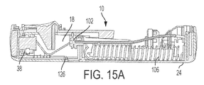
図1から図16を参照して、本発明の1つの態様による薬物送達システム10は、駆動アセンブリ12、容器14、バルブアセンブリ16、および針アクチュエータアセンブリ18を含む。駆動アセンブリ12、容器14、バルブアセンブリ16、および針アクチュエータアセンブリ18は、ハウジング20内部に少なくとも部分的に位置付けられる。ハウジング20は、上部(top portion)22および底部(bottom portion)24を含むが、ハウジング20のための他の適当なアレンジメントが利用されてもよい。1つの態様において、薬物送達システム10は、ユーザーに着用されまたは固定されるように、および容器14内部に提供された薬剤の所定の投与量を注射を介してユーザーに送達するように、構成された注射器デバイスでる。システム10は、設定された時間内に薬剤が送達される「ボーラス注射(bolus injection)」を送達するために利用されてもよい。薬剤は、45分までの時間を越えて送達されてもよいが、他の適当な注射量および継続時間が利用されてもよい。ボーラス投与または送達は、速度制御を用いてまたは何ら特定の速度制御を有さずに、実行され得る。システム10は、薬剤を、固定圧力において速度可変で、ユーザーに送達してもよい。システム10の概略的な動作は、図1から図16を参照して以下に記載され、それと共に、駆動アセンブリ12、針アクチュエータアセンブリ18、およびシステム10の他の機能の仕様は、図17から図93と関連して以下に論じられる。
Referring to FIGS. 1-16, a
図1から図16を再び参照して、システム10は、ユーザーによる作動ボタン26の係合を通して動作するように構成され、これは、ユーザーの皮膚を貫通する針アセンブリ18の針28、容器14と流体連通する針28を配置しおよび流体または薬剤を容器14から放出する駆動アセンブリ12の作動、ならびに薬剤の注射が完了した後の針28の退避(withdrawal)をもたらす。薬物送達システムの概略的な動作は、その全体が参照によって本明細書に組み込まれる、特許文献1および特許文献2に示されおよび記載される。システム10のハウジング20は、システム10のステータスに関してユーザーに表示を与えるように構成された表示器(indicator)アレンジメント32を見るための表示器窓30、および容器14を見るための容器窓31を含む。表示器窓30は、表示器アレンジメント32のはっきりとしたビューを提供するための拡大レンズであってもよい。表示器アレンジメント32は、システム10の使用の間、針アクチュエータアセンブリ18に沿って移動して、システム10の使用前ステータス、使用ステータス、および使用後ステータスを表示する。表示器アレンジメント32は、ステータスについての視覚的な表示を提供するが、他の適当な表示、例えば聴覚的または触覚的なものが代替物または付加的な表示として提供されてもよい。
Referring again to FIGS. 1-16, the
図4から図6を参照して、システム10が使用前状態にある間、容器14は、駆動アセンブリ12およびバルブアセンブリ16から間隔が空けられ、ならびに針28は格納状態にある。図7から図9に示されるように、システム10の当初作動の間、駆動アセンブリ12は容器14と係合して容器14をバルブアセンブリ16に向かって移動させ、これは、容器14のクロージャ36を貫通しおよびチューブ(不図示)または他の適当なアレンジメントを介して針28と流体連通する容器14内部に薬剤を配置するように構成される。駆動アセンブリ12は、容器14のストッパー34と係合するように構成され、これは、当初、容器14内部の流体または薬剤の非圧縮性のために容器14全体をバルブアセンブリ16と係合するように移動させることとなる。システム10の当初作動は、ユーザーによる作動ボタン26の係合によって引き起こされ、これは、以下により詳細に論じられるように、針アクチュエータアセンブリ18および駆動アセンブリ12をリリースする。当初作動の間、針28は、まだ格納状態にあり、およびシステム10のユーザーに注射するために、延ばされた状態にまさに移動しようとしている。
4-6, while
システム10が使用状態にある間、図10から図12に示されるように、針28は、ハウジング20の少なくとも部分的に外側の延ばされた状態にあり、駆動アセンブリ12は、容器14内部においてストッパー34を移動させて、薬剤を容器14から針28を通しておよびユーザーに送達する。使用状態において、バルブアセンブリ16は、既に、針28と流体連通する容器14を配置するために容器14のクロージャ36を貫通しており、これはまた、流体は容器14から分注されることができるので、駆動アセンブリ12が容器14に対してストッパー34を移動させることを可能にする。図13から図15に示されるシステム10の使用後状態において、針28は、格納状態にあり、および針28を封止しおよび容器14からの流体または薬剤の何らかの残留流れを防止するように、パッド38と係合される。容器14およびバルブアセンブリ16は、参照によってその全体が本明細書に組み込まれる特許文献3に示されおよび記載される、容器14およびバルブアセンブリ16であってもよい。
While the
図15Aから図15Cを参照して、パッド38は、針アクチュエータ本体96が使用状態から使用後状態に移動する際に、パッド内に付勢される。具体的には、パッド38は、ハウジング20の底部24上のカムトラック126と協働するカム面124を有するパッドアーム122によって受け入れられる。パッドアーム122は、トーションンバー128を介して針アクチュエータ本体96に接続される。カム面124は、カムトラック126と係合してパッドアーム122を下向きに偏向させるように構成され、それによって、パッド38が、上向きに針28内に付勢される前に針28の下を通ることを可能にする。トーションンバー128は、パッドアーム122が針アクチュエータ本体96の旋回軸の周りに巻き付く(twist about)のを可能にする。パッド38は、パッドアーム122の開口内に圧入されてもよいが、パッド38を固定するための他の適当なアレンジメントが利用されてもよい。
Referring to FIGS. 15A-15C,
図1から図33を参照して、本発明の1つの態様による駆動アセンブリ12が示される。上述されたように、駆動アセンブリ12は、容器14を移動させて容器14のクロージャ36を貫通させるように、およびまた、容器14内部においてストッパー34を移動させて容器14から流体または薬剤を分注するように、構成される。図17から図33に示される駆動アセンブリ12は、容器14のストッパー34によって受け入れられるスペーサアセンブリ40と係合しおよび協働するように構成される。スペーサアセンブリ40は、スペーサ42およびスペーサホルダー44を含む。スペーサホルダー44はストッパー34によって受け入れられ、およびスペーサ42はスペーサホルダー44によって受け入れられる。スペーサホルダー44は、ストッパー34の対応するねじ山付き部分と係合する第1のねじ山付き部分46を含むが、他の適当なアレンジメントが利用されてもよい。スペーサ42は、また、スペーサ42をスペーサホルダー44に固定するために、スペーサホルダー44の対応する第2のねじ山付き部分50と係合するねじ山付き部分48も含むが、他の適当なアレンジメントが利用されてもよい。駆動アセンブリ12は、投与終了後の針28の格納、および駆動アセンブリ12によるストッパー34の突然の(abrupt)係合を最小限にもしながらシステム10のステータスの表示を提供すること、を含むがこれに限定されない上述されたシステム10の機能的特徴を維持しながら、容器14の様々な所定の充填体積を分注するように構成される。駆動アセンブリ12は、複数のサイズのスペーサ42を利用することによって複数の別個の充填体積範囲を分注するように構成される。1つの態様において、12個の充填体積範囲および12個のスペーサ42サイズが設けられる。1つの態様において、スペーサ42の長さは、容器14内に異なる充填体積を収容するように変更される。あるいはまた、スペーサ42によって受け入れられる複数のシムを利用することによって収容される容器14内に複数の(a range of)充填体積を持つ単一サイズのスペーサ42が利用されてもよい。
With reference to FIGS. 1 to 33, a
図17から図26を参照して、駆動アセンブリ12は、第1のプランジャ部材52、第1のプランジャ部材52によって受け入れられる第2のプランジャ部材54、第1の付勢部材56、第2の付勢部材58、プランジャ作動部材60、およびインデックス部材62を含む。第1のプランジャ部材52は、使用前状態(図18に示される)から、使用状態(図19に示される)まで、使用後状態(図20に示される)まで、移動可能であり、第1のプランジャ部材52は、スペーサアセンブリ40と係合しおよび容器14内部においてストッパー34を移動させて容器14から薬剤を分注するように構成される。第1のプランジャ部材52は、軸方向に移動するように構成される。第2のプランジャ部材54および第1のプランジャ部材52は、入れ子式(telescoping)アレンジメントを形成し、第2のプランジャ54は、第1のプランジャ部材52が所定の軸方向距離移動した後に軸方向に移動するように構成される。第1および第2のプランジャ部材52、54の移動は、第1および第2の付勢部材56、58によって提供され、これは圧縮ばねであるが、付勢部材56、58のための他の適当なアレンジメントが利用されてもよい。
Referring to FIGS. 17-26, the
第1の付勢部材56は、第2のプランジャ部材54によって受け入れられ、およびプランジャ作動部材60(およびインデックス部材62)と第2のプランジャ部材54の第1のばね座64との間に拘束される。第2の付勢部材58は、第1の付勢部材56から半径方向内向きに位置付けられ、および第2のプランジャ部材54によって受け入れられる。第2の付勢部材58は、第2のプランジャ部材54の第2のばね座66と第1のプランジャ部材52との間に拘束される。第2の付勢部材58は、第1のプランジャ52部材を、容器14に向かって使用前状態から使用状態におよび使用後状態に付勢するように構成される。第1の付勢部材56は、第2のプランジャ部材54を容器14に向かって付勢するように構成され、これは、次に、第1のプランジャ部材52を容器14に向かって使用前状態から使用状態におよび使用後状態に付勢する。より具体的には、第2の付勢部材58は、第1のプランジャ部材52をスペーサアセンブリ40またはストッパー34に対抗して駆動して容器14をバルブアセンブリ16内に係合するように移動させ、それによって容器14のクロージャ36を貫通しおよび容器14を針28と流体連通して配置するように構成される。第1の付勢部材56は、容器14内部においてストッパー34を移動させて容器14内部の薬剤を分注するように構成される。第2の付勢部材58は、第1の付勢部材56とは異なるばね定数を有する。具体的には、第2の付勢58部材は、第1の付勢部材56より硬くて容器14のクロージャ36を貫通するための高い力を提供し、一方、第1の付勢部材56は、容器14内部の流体または薬剤の粘度に適当であるような分注するためのより低い力を提供する。
The first biasing member 56 is received by the
再び図17から図26を参照して、プランジャ作動部材60は、環状部分68およびスピンドル部分70を有する。プランジャ作動部材60は、第1の回転状態と第1の回転状態から間隔が空けられた第2の回転状態との間において第1のプランジャ部材52に対して回転式に移動可能である。第1の回転状態は、第2の回転状態から15度であってもよいが、他の適当な状態が利用されてもよい。環状部分68は、複数のギア74を含む駆動表面72を含むが、駆動表面72のために他の適当なアレンジメントが利用されてもよい。スピンドル部分70は、第1のプランジャ部材52のプランジャ係止表面78との係合および第1のプランジャ部材52のプランジャ係止表面78からのリリースのために構成されたアクチュエータ係止表面76を含む。プランジャ係止表面78は、前記アクチュエータ係止表面76によって画定される複数のスロットまたはカットアウト81によって受け入れられるように構成された複数の突出部80を含む。
Referring again to FIGS. 17-26,
図18および図23に示されるように、プランジャ作動部材60の第1の回転状態において、複数の突出部80および複数のスロットまたはカットアウト81は、プランジャ作動部材80が第1のプランジャ部材52と係合するように、整列しておらず(out of alignment)、第1および第2の付勢部材56、58が第1および第2のプランジャ部材52、54をプランジャ作動部材60から離れて付勢する状態で、第1および第2のプランジャ部材52、54の移動を防止する。図19および図24に示されるように、プランジャ作動部材60の第2の回転状態において、複数の突出部80および複数のスロットまたはカットアウト81は、プランジャ作動部材60が第1のプランジャ部材52から係合解除されて第1および第2のプランジャ部材52、54の移動を可能にし、それによって容器14からの分注プロセスを開始するように、互いに整列している。
As shown in FIGS. 18 and 23, in the first rotational state of the
図7および図33を参照して、プランジャ作動部材60の駆動表面72は、針アクチュエータアセンブリ18の一部によって係合されることとなるように構成される。以下により詳細に論じられる、アクチュエータボタン26の係合および針アクチュエータアセンブリ18のリリースの後、針アクチュエータアセンブリ18は、ハウジング20内部において使用前状態から使用状態におよび使用後状態に移動する。針アクチュエータアセンブリ18の当初移動の間、針アクチュエータアセンブリ18の一部は、プランジャ作動部材60の駆動表面72と係合して、プランジャ作動部材60を第1の回転状態から第2の回転状態に移動させる。図33に示されるように、針アクチュエータアセンブリ18の角度が付いた(angled)ブレード部分82は、プランジャ作動部材60の駆動表面72と係合して、プランジャ作動部材60の回転を引き起こす。
Referring to FIGS. 7 and 33,
図11、図13、および図26を参照して、第2のプランジャ部材52は、複数のコード化された突出部84を含み、あらかじめ選択された複数のコード化された突出部84のうちの1つは、システム10の制限部材86と係合するように構成される。以下により詳細に論じられるように、制限部材86は、針作動アセンブリ18と協働し、およびストッパー34の所定の投与終了状態(end-of-dose position)に達するまで、針アクチュエータアセンブリ18の使用状態から使用後状態までの移動を制限する。1つの態様において、制限部材86は、制限部材86と針作動アセンブリ18の一部との間の係合を通して、使用状態からの針作動アセンブリ18の軸方向移動を制限するように構成される。制限部材86と針作動アセンブリ18との間のそのような係合は、ストッパー34が投与終了状態に達したときに、制限部材86の回転によってリリースされる。針アクチュエータアセンブリ18が使用状態にある間、制限部材86は、制限部材86の回転が制限部材86と第2のプランジャ部材54の複数のコード化された突出部84のうちの1つとの間の係合を通して防止された状態で、回転方向に付勢される。複数のコード化された突出部84は、様々な長さの軸方向リブであってもよいが、他の適当なアレンジメントが利用されてもよい。各コード化された突出部84は、制限部材86が回転しそれによって針アクチュエータアセンブリ18をリリースすることができる状態を画定する。第2のプランジャ部材52の滑らかな部分は、また、システム10が投与終了状態にいつ移行するかを決定するためのさらなる「コード」を提供してもよい。
Referring to FIGS. 11, 13 and 26, the
上で論じられるように、表示器アレンジメント32は、システム10が使用前状態、使用状態、および使用後状態または投与終了状態から移動する際に、表示器アレンジメント32の異なる部分が表示器窓30を通して見ることができる状態で、移動する。より具体的には、表示器アレンジメント32は、制限部材86の一部と係合し、および制限部材86と一緒にシステム10の様々な段階を通って移動して、システム10の状態に関してユーザーに表示を提供する。
As discussed above, as the
システム10の組み立ての間、容器14の投薬量は、設定長を有する特定のスペーサ42と適合させられ、および対応する複数のコード化された突出部84のうちの1つは、制限部材86と整列させられる。したがって、上で論じられるように、容器14には、各体積が特定のスペーサ42およびコード化された突出部84に対応する、複数の投薬量体積が設けられていてもよい。したがって、異なる投薬量体積に関してさえ、システム10は、針28をユーザーに注射して、容器14から薬剤の投与量を送達し、投与終了後に針28を格納し、および駆動アセンブリ12によるストッパー34の突然の係合を最小限にしながらシステム10のステータスの表示を提供するように構成される。具体的には、ストッパー34のサイズは、第1のプランジャ部材52とスペーサアセンブリ40との間の距離を最小限にするように選択されてもよく、およびダンピングの使用を必要としない。
During assembly of the
図27から図33を参照して、本発明のさらなる態様による駆動アセンブリ12Aが示される。図27から図33に示される駆動アセンブリ12Aは、図17から図26に示されおよび上述された駆動アセンブリ12と類似しておりおよび同様の方法で作動する。しかしながら、図27から図33の駆動アセンブリにおいて、第1のプランジャ部材52は、第2のプランジャ部材54によって受け入れられ、および使用前状態から使用状態への軸方向移動の間、第2のプランジャ部材54から延びる。さらに、第1のプランジャ部材52は、第1および第2のプランジャ部材52、54が一緒に移動するように、第1のプランジャ部材52が所定の軸方向距離移動した後に第2のプランジャ部材54と係合するように構成される延長部分88を含む。第1および第2の付勢部材56、58は、図17から図26の駆動アセンブリ12と同様の方法で、第1および第2のプランジャ部材52、54と係合しおよびこれらに作用する。
Referring to FIGS. 27-33, a
図27から図32を参照して、インデックス部材62は、第1および第2のプランジャ部材52、54の周りに位置付けられ、およびハウジング20の底部24に位置付けられる可撓性タブ92と係合するように構成された複数のラチェット歯90を含む。駆動アセンブリ12、12Aがハウジング20の底部24内に取り付けられたとき、インデックス部材62のラチェット歯90とハウジング20の可撓性タブ92の係合は、インデックス部材62の一方向の回転を提供する。インデックス部材62は、上で論じられるように、回転して、第2のプランジャ部材52のコード化された突出部84のうちの1つを投薬量体積およびスペーサ42サイズに基づいて制限部材86と整列させるように構成される。インデックス部材62は、駆動アセンブリ12、12Aに24個の回転状態を提供してもよく、そのうちの12個はそれらと関連付けられた唯一の投与量値を有していてもよい。
Referring to FIGS. 27-32,
図1から図16および図34から図40Bを参照して、本発明の1つの態様による針アクチュエータアセンブリ18が示される。針アクチュエータアセンブリ18は、上で論じられるように、ガイド面98を有する針アクチュエータ本体96、カム面104を有する針シャトル102、ならびに針シャトル102によって受け入れられおよび容器14と流体連通するように構成された針28を含む。針アクチュエータ本体96は、概して矩形であり、半径方向内向きに突出するガイド面98を備える。針シャトル102は、針アクチュエータ本体96内部に受け入れられる。上述されたように、針アクチュエータ本体96は、ハウジング20内部において、使用前状態(図4から図6に示される)、当初作動状態(図7から図9)、使用状態(図10から図12)、および使用後状態(図13から図15)から移動可能である。針アクチュエータ本体96は、引張ばね106を介して使用前状態から使用後状態に付勢されるが、他の適当な付勢アレンジメントが利用されてもよい。針アクチュエータ本体96は、アクチュエータボタン26の係合に際してリリースされおよび使用前状態から使用状態まで自由に移動でき、これは以下により詳細に論じられる。針アクチュエータ本体96は、図17から図33と関連して上で論じられるように、制限部材86の回転後に、使用状態から使用後状態に移動する。
With reference to FIGS. 1-16 and 34-40B, a
図34から図40Bを参照して、針シャトル102は、針28がハウジング20内部に位置付けられる格納状態と針28の少なくとも一部がハウジング20の外に延びる延ばされた状態との間において垂直軸に沿って移動可能である。針シャトル102は、針アクチュエータ96のガイド面98と針シャトル102のカム面104との間の係合を通して、格納状態と延ばされた状態との間において移動するように構成される。カム面104は、第1および第2のカム部材108、110によって提供され、第1のカム部材108は、第2のカム部材110から間隔が空けられる。ハウジング20は、針シャトル102上にT字形突出部114を受け入れるように構成された凹部を有するガイドポスト112を含むが、他の形状および構成がガイドポスト112およびT字形突出部114のために利用されてもよい。針シャトル102は、格納状態と延ばされた状態との間においてガイドポスト112に沿って移動する。ガイドポスト112は、直線状(linear)でありハウジング20からほぼ垂直に延びるが、他の適当なアレンジメントが利用されてもよい。針アクチュエータ本体86のガイド面98は、非直線状(nonlinear)であり、ならびに各々、第1の側116および第1の側116の反対に位置付けられた第2の側118を含む。
With reference to FIGS. 34-40B,
以下に論じられるように、針アクチュエータ本体96のガイド面98は、針アクチュエータ本体96が使用前状態から使用後状態まで軸方向に移動する際に、針シャトル102のカム部材108、110と協働して、針シャトル102を格納状態と延ばされた状態との間において垂直に移動させる。針シャトル102は、また、ハウジング20またはアクチュエータボタン26と係合するように構成されたシャトル付勢部材120も含む。具体的には、シャトル付勢部材120は、ハウジング20またはアクチュエータボタン26と係合し、および針アクチュエータ本体96が使用状態から使用後状態まで移行するときに付勢力を提供する。針アクチュエータ本体96が使用後状態に完全に移行されたとき、針シャトル102のカム部材108、110は、針アクチュエータ本体96のガイド面98から係合解除され、およびシャトル付勢部材120は、上で論じられるように、針28がパッド38と係合するように、針シャトル102を下向きに付勢する。しかしながら、図1から図16と関連して、パッド38もまた、上で論じられるように、シャトル付勢部材120を介して針シャトル102を下向きに付勢するのではなく、針28内に付勢されてもよい。針アクチュエータ本体96は、アクチュエータボタン26と相互作用して、使用後状態に達するまでアクチュエータボタン26が飛び上がってくるのを防止してもよく、これは以下により詳細に論じられる。
As discussed below, the
図37Aから図40Bを参照して、使用前状態(図37A)において、針シャトル102は格納状態にあり、カム部材108、110は、針アクチュエータ本体96のガイド面98から間隔が空けられている。針アクチュエータ本体96が使用状態(図37Bおよび図38A)まで移動する際に、針シャトル102の第2のカム部材110は、ガイド面98の第2の側118と係合して、針シャトル102を格納状態から延ばされた状態に移動させる。針アクチュエータ本体96の使用状態から使用後状態までの移行の間(図37C)、針シャトル102の第1のカム部材108は、ガイド面98の第1の側116と係合して、針シャトル102を第2の状態から第1の状態に移動させる。針アクチュエータ本体96が使用後状態(図37Dおよび図38B)まで完全に移行された後、シャトル付勢部材120は、カム部材108、110が針アクチュエータ本体96のガイド面98から係合解除する際に、針28がパッド38と係合する状態で、針シャトル102を下向きに付勢する。また、針アクチュエータ本体96および針シャトル102の対応する状態の移行も図39から図40Bに示される。アクチュエータボタン26と針アクチュエータ本体96との間の相互作用は、図65Aから図67と関連して詳細に論じられる。図41から図64を参照して、さらなる実施形態による薬物送達システム200が示される。システム200は、上側ハウジング204および下側ハウジング206を有するハウジング202を含む。ハウジングは、近位端205および遠位端207を有する。上側ハウジング204は、ユーザーがシステム200の動作(operating)ステータスを見ることができるように、ステータスビューポート208を有する。システム200は、また、バルブアセンブリ212、バルブアセンブリ214を針アーム216の近位端に配置される患者針215と流体的に接続するチューブ214を含む。ばね218は、針アクチュエータ220を遠位に付勢する。
Referring to FIGS. 37A-40B, in the pre-use condition (FIG. 37A), the
図42から図46に示されるように、システム200は、付加的に、その中に移動可能に配置されるストッパー224を備える容器または薬剤容器222を含むが、ストッパー224は、明確さを助けるために様々な図から省略されている。好ましくは、薬剤容器222の遠位端は、図47に最もよく示されるように、デバイス222の作動の前にバルブアセンブリ212から間隔が空けられるセプタムアセンブリ228を有する。
As shown in FIGS. 42-46, the
製造目的のために、容器との使用のためにたとえ多数の充填体積または投薬量が考えられたとしても、薬剤容器のための1つのサイズを使用することは多くの場合望ましい。そのような場合において、薬剤容器が充填されたとき、充填体積を異ならせることは、ストッパーの異なる状態(different positions)をもたらす。ストッパーの製造の違いに適応するだけでなくそのような異なるストッパー状態に適応するために、本発明の態様は、容器222の近位端内でストッパー224の近位に配置される特注またはカスタムスペーサ226を含む。換言すれば、特注スペーサ226は、異なるスペーサ226を選択することによって、製造業者が設定したあらかじめ定義された様々な充填体積の分注を可能にするオプションを提供し、およびアセンブリ構成の動作の必要性を低減または排除する。スペーサ226のサイズは、容器222の充填未満の(under-filled)体積を構成するように採用され、および容器の近位端において一貫した圧迫面(bearing surface)を提供することができる。
For manufacturing purposes, it is often desirable to use one size for a drug container, even if multiple fill volumes or dosages are considered for use with the container. In such cases, when the drug container is filled, making the filling volume different results in different positions of the stopper. In order to accommodate differences in the manufacture of the stoppers as well as to accommodate such different stopper conditions, aspects of the present invention may be custom or custom spacers disposed proximal to the
スペーサ226は、ストッパー224の近位端から容器222の近位端までの空間を占有するように、複数の異なるサイズのスペーサ226から選択される。1つの実施形態によると、図45から図47に示されるように、スペーサ226は、容器222の近位端と実質的に同一平面であるように選択される。加えて、1つの実施形態によると、スペーサ226は、図45に最もよく示されるように、中央の柱230および遠位フランジ232を含む「シルクハット」形状を有する。
図44から図47を参照して、システム200は、また、容器222を遠位に変位させて容器222と患者針215との間の流体接続を確立し、以て容器222から薬剤を分注するための駆動アセンブリ234を含む。より詳細には、駆動アセンブリ234は、中央プランジャ238内部に配置される内側ばね236、外側プランジャ240、中央プランジャ238と外側プランジャ240との間に配置される外側ばね242、入れ子式部材244、およびリリースゲート246を含む。
Referring to FIGS. 44-47,
好ましくは、内側ばね236は、外側ばね242よりも大きいばね定数を有し、およびえ従って、外側ばね242よりも強くまたは硬い。内側ばね236は、中央プランジャ238の内部に配置され、および下側ハウジング内のばねフランジ248(図46に最もよく示される)と中央プランジャ238との間を押圧し、これは、デバイス起動に続いて、スペーサ226の近位端を直接的に圧迫する。外側ばね242は、外側プランジャ240の内側に配置され、および中央プランジャ238の近位外部フランジ250と外側プランジャ240の遠位内部フランジ252との間を押圧する。したがって、内側および外側ばね236および242は、ネスト化され、および単一のばねを採用するよりも、よりコンパクトな駆動アセンブリ(およびしたがって、よりコンパクトなシステム200)を提供することができる。
Preferably, the
1つの態様によると、内側ばね236は、容器222を変位させて患者針215との流体接続を確立するようにだけ作用し、および外側ばね242は、続いて容器222から薬剤を分注するようにだけ作用する。別の態様によると、内側ばね236は、容器222を変位させて患者針215との流体接続を確立するように作用し、およびまた、容器222から薬剤を分注し始めるようにも作用し、ならびに外側ばね242は、薬剤の分注を完了するように作用する。さらなる態様において、内側ばね236は、容器222の当初貫通をもたらし、外側ばね242は、貫通を完了させおよび容器222から薬剤を分注する。
According to one aspect, the
図44から図47に示されるように、および続いてより詳細に記載されるように、外側プランジャ240は、各々リリースゲート上の対応する傾斜面(単数または複数)と相互作用する傾斜面を有してデバイス200の作動の後にパワーモジュールを保持しおよび続いてリリースする、1組の近位フランジまたは足部(feet)254を含む。
As shown in FIGS. 44-47 and as subsequently described in more detail, the
図46および47に最もよく示されるように、最初に組み立てられる際に、容器222は、駆動アセンブリ234およびバルブアセンブリ212からのクリアランス内に配置される。針アクチュエータ220上の横方向フランジ256は、薬剤容器222を軸方向に保持し、および針アクチュエータ220は、リリースゲート246が横方向に変位するのを防止する。1つの実施形態によると、ばね(不図示)は、針アクチュエータ220を遠位に付勢するが、作動ボタン210(および/またはその関連アセンブリ)は、デバイス200の作動の前の針アクチュエータ220の遠位変位を防止する。ステータスバー258は、針アクチュエータ220上に配置され、およびステータスビューポート208を通して見ることができる上面を有する。1つの実施形態によると、ステータスバーの上面は複数の色またはパターンを有し、およびデバイスが作動前(pre-actuated)ステートにあるときに、ステータスビューポート208を通して黄色のような第1の色またはパターンを見ることができる。
As first shown in FIGS. 46 and 47, the
図48から図52は、システム200の作動時およびシステム200の作動に続くイベントの動作およびシステム200の上面図である。図47において、ユーザーは、作動ボタン210を近位にスライドさせ、および次いでボタン210をハウジング202内に垂直に変位させ、それによって針アクチュエータ220を自由にしてばね(明確性のために省略される)の影響下で遠位に変位させる。図49に示されるように、針アクチュエータが遠位に変位する際に、針アクチュエータ220上のトラック260は、針アーム216上の横方向ボス262と相互作用して患者針215を挿入する。好ましくは、この段階において、針アクチュエータ220の近位端はリリースゲート246をまだ通過しておらず、およびしたがって駆動アセンブリ234はまだリリースされていない。しかし、横方向フランジ256は遠位に変位しており、およびしたがって容器222は抑止されない(unrestricted)。
48-52 are top views of the operation of the
続いて、図50および図51に示されるように、継続する遠位変位により、針アクチュエータ220の近位端は、リリースゲート246を通過する(それによって駆動アセンブリ234をリリースする)。針アクチュエータ220は、回転可能なリリースフリッパー264上の機能に一時的に寄り掛かる(rest against)ようになり、入れ子式部材244のアウトリガー266(図44および図59に最もよく示される)に対抗してリリースフリッパー264を駆動する。針アクチュエータ220は、薬剤が分注されるまでこの状態に留まる。この状態において、好ましくは、ステータスビューポート208を通して緑色のようなステータスバー258の第2の色またはパターンを見ることができる。
Subsequently, as shown in FIGS. 50 and 51, the continued distal displacement causes the proximal end of
この段階において、ばね236および242の力、および近位フランジまたは足部254の角度が付いた表面とリリースゲート246上の対応する角度が付いた表面(単数または複数)の相互作用は、リリースゲート246を横方向に変位させ、それによって外側プランジャ240をリリースゲート246との抑止相互作用から自由にする。ここに至るまでに、外側プランジャ240は中央プランジャ238を抑止している。
At this stage, the forces of the
図52および図53を参照して(内側ばね236は明確性のために図52から省略されている)、硬い内側ばね236は、スペーサ226と接触するように中央プランジャ238を遠位に駆動する。薬剤容器222は、実質的には非圧縮性の流体で満たされているので、中央プランジャ238の継続する遠位変位は、ハウジング202に対してスペーサ226、ストッパー224、および容器222を遠位に変位させる。この遠位変位は、セプタムアセンブリ228がバルブアセンブリ212によって貫通される原因となり、容器222と患者針215との間において流体連通を確立する。中央プランジャ238は、その近位外部フランジ250(図59に最もよく示される。)が下側ハウジング206上のフランジと接触するまで遠位に移動し、それによって「貫通移動(piercing travel)」を限定する。好ましくは、針アクチュエータ220の下側ハウジング206および/または横方向フランジ256上の別のフランジは、容器222の遠位移動(distal travel)を限定する。
Referring to FIGS. 52 and 53 (
続いて、図54および図55に示されるように、内側ばね236はもはや中央プランジャ238を遠位に変位させることができないので、より軽い外側ばね242が、スペーサ226の遠位フランジ232と接触するように外側プランジャ240を中央プランジャ238に対して遠位に変位させる。続いてより詳細に記載されるように、好ましくは、外側プランジャ240とスペーサ226との間の接触は、衝撃力を最小限にするようにダンピングされる。外側ばね242のさらなる拡張(expansion)は、外側プランジャ240を遠位に変位させて薬剤を分注する。
Subsequently, as shown in FIGS. 54 and 55, the lighter
図56および図57に示されるように、外側ばね242が拡張しおよび外側プランジャ240を遠位に変位し続ける際に、入れ子式部材244に対する外側プランジャ240の所定の遠位変位に際して、外側プランジャ240のフランジ268の外部機能は、入れ子式部材244の内部遠位機能またはフランンジ270と相互作用して入れ子式部材244を「ピックアップ」する。これは、外側プランジャ240のさらなる遠位変位が入れ子式部材244の対応する遠位変位をもたらすことを保証する。この対を成す遠位変位は、薬剤分注の終了まで継続する。
As shown in FIGS. 56 and 57, as the
先述のように、アウトリガー266は、入れ子式部材244上に配置される。アウトリガーの軸方向長さおよび入れ子式部材144の遠位移動は、アウトリガー266とリリースフリッパー264の係合解除のタイミングを支配する。図58および図59に示されるように、薬剤分注の終わりにおいて、アウトリガー266の近位端はリリースフリッパー264をバイパスする。これは、リリースフリッパー264が針アクチュエータ220との係合を脱して回転することを可能にし(図60)、および針アクチュエータ220がその遠位変位を継続しおよび患者針215を退避させることを可能にする(図61)。この段階において、ステータスビューポート208を通して、デバイス200が動作を完了したことを示す、赤色のようなステータスバー258の別の色またはパターンを見ることができる。
As mentioned above, the
先述のように、図62および図63に示されるような外側プランジャ240とスペーサ226との間の接触は、好ましくは、衝撃力を最小限にするようにダンピングされる。最高レベルのエネルギー散逸は、所望の分注速度を提供するために外側ばね242がより硬くなるので、粘性流体を含有する充填未満のシリンジのために望ましい。最低レベルのエネルギー散逸は、所望の分注速度を提供するために外側ばねが少ししか硬くならない可能性があるので、低粘度の流体を含有する最大限に充填されたシリンジのために望ましい。空気ダンピングまたは独立気泡(closed-cell foam)ダンピングのようなダンピングレベルを調節するために、様々な方法が採用され得る。
As mentioned previously, the contact between the
衝撃力をダンピングする別の方法として、図64は、1つまたは複数の軸方向インターフェースリブ272がその中でスペーサ226の中央の柱230の周りに周方向に配列される、スペーサ226の実施形態を示す。この実施形態において、外側プランジャ240は、干渉リブ(interference rib)272を通り過ぎなければならず、これはスペーサ226に対する外側プランジャ240の遠位変位に摩擦抵抗を提供する。干渉リブ272と外側プランジャ240との間の干渉によって作り出された摩擦力は、プランジャスピードから独立している。好ましくは、摩擦力は、最小限の分注ばね荷重を超えず、より弱いばねを失速させることを回避する。干渉は、所望のレベルの摩擦抵抗を与えるように調節され得る。異なる流体粘度のために、干渉リブ272の異なるサイズ設定(軸方向および/または半径方向)があり得る。これは、各粘度および充填レベルの組み合わせのための、または粘度範囲に必要とされるばねの数による、特注またはカスタムスペーサを意味することができ、いくつかの枝を持つ状態(a number of tined positions)があり得、それによってスペーサは、特定のモジュラーばねのための特定の状態(その状態は、その特定のばね荷重/粘度シナリオのために調節された干渉/ダンピングを有している)に設定され得る。
As another method of damping the impact force, FIG. 64 shows an embodiment of a
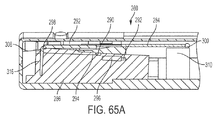
図65Aから図69を参照して、本発明の1つの態様によるシステム10を作動させるためのアクチュエータボタンアレンジメント280が示される。アクチュエータボタンアレンジメント280は、アクチュエータボタン26、ボタンばね284、および針アクチュエータ本体286を含む。針アクチュエータ本体286は、上で論じられた針アクチュエータ本体96、220と類似しおよびハウジング20内部において移動するように構成されて、針シャトル102または針28を格納と延ばされた位置との間において移行させてもよい。図69に示されるように、アクチュエータボタン26は、ユーザーと相互作用するためのユーザーインターフェース部288を含む。好ましくは、ユーザーインターフェース部288は約22mm長さおよび約10mm幅であるが、他の適当な寸法が利用されてもよい。アクチュエータボタン26は、デバイス作動の前に針アクチュエータ本体286上のボタン接触面294、296と相互作用する2対のロックアウトアーム290、292を含んで、針アクチュエータ本体286が上向きに揺動するのを防止する。図65Hに示されるように、針アクチュエータ本体286とハウジング20との間の重なりは、時期尚早な作動を防止する。図66を参照して、ボタンばね284は、第1の圧迫面298および第1の圧迫面298から間隔が空けられた第2の圧迫面300、ならびに第1の圧迫面298によって結合される1対の外側アーム304によって取り囲まれた片持ち梁式中央ばねアーム302を含む。
Referring to FIGS. 65A-69, an
作動ボタンアレンジメント280は、次の機能のうちの1つまたは複数を提供するように構成され、これは以下により詳細に論じられる:アクチュエータボタン26の一方向の軸方向変位またはスライド;針アクチュエータ本体286が使用状態にある間、アクチュエータボタン26が押し下げられたままである、アクチュエータボタン26の横移動(transverse movement)(隆起(raised)状態および押下(depressed)状態);およびボタン26が隆起状態にありおよびユーザーによって押し下げられることができないような、針アクチュエータ本体286の使用後状態における、アクチュエータボタン26のロックアウト。
アクチュエータボタン26を用いてシステム10を作動させるために、ユーザーは、まず、図65Gおよび図65Hにおいて右側であるとして示される第1の軸方向にユーザーインターフェース部288をスライドさせる。ユーザーは、ユーザーインターフェース部288を約10mmまたは約8mmスライドさせることを要求されてもよいが、他の適当な距離が利用されてもよい。アクチュエータボタン26を軸方向に移動させることがロックアウトアーム290、292を移動させて、針アクチュエータ本体286上のボタン接触面294、296を通過させて、アクチュエータボタン26の隆起状態から押下状態への移動を可能にする。
To actuate the
ユーザーがユーザーインターフェース部288を遠位にスライドさせる際に、ボタンばね284の中央ばねアーム302は、ハウジング20上のばねアーム306圧迫面を乗り越え(rides over)、一方、第1および第2の圧迫面298、300は、ハウジング20上の第1および第2の圧迫ランプ308、310と係合する。ボタンばね284上の力は、ばねアーム圧迫面306および第1および第2の圧迫ランプ308、310との係合を通してバランスがとられて、アクチュエータボタン26の滑らかな軸方向変位またはスライドが提供される。
As the user slides the
アクチュエータボタン26およびボタンばね284がそれらの軸方向スライド移動(sliding travel)の終わりに達する際に、中央ばねアーム302および第1の圧迫面298は、図65Hに示されるように、それぞれのストップ312、314の端部を通過して、アクチュエータボタン26がその原状態へ後方にスライドすることを防止する。さらに、アクチュエータボタン26およびボタンばね284がそれらの軸方向スライド移動の終わりに達するときに、ユーザーは、ユーザーインターフェース部288と係合して、アクチュエータボタン26をその押下状態に下向きに移動させる。アクチュエータボタン26は、約2mm押し下げられてもよく、およびアクチュエータボタン26を押し下げるため必要とされる最小限の力は、約3N、最も好ましくは約2.8Nであるが、他の適当な距離および最小限の力が利用されてもよい。
As the
ユーザーが図65Aおよび図65Bに示されるユーザーインターフェース部288を押し下げる際に、アクチュエータボタン26は、針アクチュエータ本体286を回転させて針アクチュエータ本体286をリリースし、それによって針アクチュエータ本体286が使用前状態から使用状態に移動するのを可能にする。図65Bに示されるように、針アクチュエータ本体286が使用状態に移動する際に、ロックアウトアーム290、292は、ボタン接触面294、296の下側に沿って走って、アクチュエータボタン26が上向きに跳ねることを防止する。薬剤が送達された後、および針アクチュエータ本体286が使用状態から図65Cに示される使用後状態に移行する際に、ロックアウトアーム290、292は、ボタン接触面294、296から係合解除されて、アクチュエータボタン26がボタンばね284の影響下で跳ねて後退することを可能にする。針アクチュエータ本体286が図65Dに示される使用後状態に完全に移行すると、アクチュエータボタン26は、ボタンばね284の付勢力に起因して、押下状態から隆起状態への移動を終了する。針アクチュエータ本体286が使用後状態にあるとき、針アクチュエータ本体286上のばねアーム316はアクチュエータボタン26と係合してアクチュエータボタン26が押下状態に移動することを防止し、一方、軸方向移動は、ばねアーム302とストップ312、314の係合によって制限されたままである。したがって、アクチュエータボタン26は、薬剤の送達が完了した後に係止されて(locked)、使用されたシステムと未使用のシステムとの間の明確な表示を提供する。
When the user depresses the
さらに、薬剤の分注の間、ユーザーがアクチュエータボタン26を押さえつけておく場合、適切な投薬および針格納は、それでもやはり完了することとなるが、アクチュエータボタン26は、ボタン26がリリースされるまで、隆起状態に跳ねて後退しないこととなる。
Furthermore, if the user holds the
1つの態様において、ボタンばね284は、プラスチック製である。また、ボタンばね284には、代わりに圧縮金属ばね(pressed metal spring)が使用されてもよいが、任意の他の適当な材料が利用されてもよい。
In one aspect, the
図68Aから図68Gを参照して、別個のアクチュエータボタン26およびボタンばね284を設けるのではなく、ばねは、ボタン26が一体的に設けられていてもよい。より具体的には、本発明のさらなる態様によるアクチュエータボタン320は、一体的ばねアーム322を含む。アクチュエータボタン320は、また、ロックアウトアーム324、保持アーム326、および後方旋回軸328を含む。図68Dおよび図68Eに示されるように、ばねアーム322は、ハウジング20の上部22においてプロング330と係合する。使用前状態から使用状態までのシステム10の移行の間、ばねアーム322は、プロング330の戻り止めを越えてスライドし、軸方向ばね力を提供する。ばねアーム322の端部は、ハウジング20の上部22の一部と係合して、ばねアーム322が偏向する際に垂直ばね力を提供する。アクチュエータボタン320は、たとえ2つの別個の動きが生じているとしてもボタン320のスライド移動と押し下げ移動との間の流体の動きを目的として構成され、これは上で論じられるボタン26の動作と類似している。使用前状態と使用状態との間の移行の間、ボタン320は、針アクチュエータ本体286の一部と係合する保持アーム326と共に後方旋回軸328の周りを旋回し、それによって、アクチュエータボタン26と同様の方法で、投与終了状態に達するまで、ボタン320の押下状態を維持する。ロックアウトアーム324は、針アクチュエータ本体286が投与終了状態まで移動する際に、内向きに偏向しおよび針アクチュエータ本体286の一部と係合し、それによって、上で論じられるアクチュエータボタン26と同様の方法で、アクチュエータボタン320のさらなる移動を防止する。
Referring to FIGS. 68A-68G, instead of providing
本発明の態様は、以前のボタン設計を超える改善をもたらす。例えば、作動ボタンアレンジメント280は、複数の表面を提供して、作動の前に針アクチュエータ本体286を針アクチュエータのばね106に対抗して適所に保持し、それによって、落下衝撃の間の時期尚早な作動の可能性を低減させる。作動ボタンアレンジメント280は、表面が分離しおよび事前に起動する余地がないような方法で、傾けられた(係止された)状態でそれを保持することによって、針アクチュエータ本体286が作動の前に移動することを物理的に防止する。
Aspects of the invention provide an improvement over previous button designs. For example, the
加えて、作動ボタンアレンジメント280のボタンスライド力は、単純な突起(bump)戻り止めを使用するのではなく、屈曲アームを利用することによって、より正確に制御される。これは、よりよい力制御と共に、ボタン26のより長いスライドストロークを可能にし、より人間工学的に有効な設計をもたらす。さらに、作動ボタンアレンジメント280は、ボタン26を注射の終わりに飛び出て戻るようにさせ、ユーザーに薬剤送達が完了したという付加的な視覚的、聴覚的、及び触覚的表示を与える。
In addition, the button slide force of the
1つの態様によると、システム10の流体送達体積は、実際の充填体積、容器内径、ならびにストッパー開始状態および長さに関わらず、ハウジング内側の点に対するプランジャの終了状態(end position)によって決定される。上記要因の公差は極めて大きい可能性があるので、投薬精度の可変性は、重要であり得る。本発明の態様は、投薬式(dosing equation)由来のこれらの公差のいくつかまたは全ての排除を可能にし、薬剤のより正確な及びより変動しない注射体積をもたらす。
According to one aspect, the fluid delivery volume of
図70Aから図70Gを参照して、本発明の1つの態様による駆動アセンブリと関連する使用のためのスペーサアセンブリ400が示される。
Referring to FIGS. 70A-70G, a
ストッパースペーサアセンブリ400における公差の連鎖内の要素は、内側プランジャ404のフランジ402の厚さ(A)、内部近位端408と内部肩部410との間の外側プランジャ406の内部長さ(B)、および内側プランジャフランジ402と外側プランジャの内部近位端408との間の当初オフセット距離(C1)を含む。この当初オフセット距離(C1)は、好ましくは、外側プランジャ406と薬剤バレル412の近位端との間のギャップ距離(C2)よりも大きい。ストッパースペーサアセンブリ400における公差の連鎖は、また、内部バレル直径(D)を含む。組み立てられると、ストッパースペーサ414および外側プランジャ406は、所与の薬剤体積のために唯一となる。
The elements in the tolerance chain in the
図70Bから図70Gは、ストッパースペーサアセンブリ400の動作を示す。図70Bに示されるように、システムが作動させられるとき、内側および外側プランジャ404および406の両方がリリースされる。外側ばね416は、外側プランジャ406をバレル412内に押し、ダンピング材料418、および内側ばね420を圧縮する。ストッパー422は、薬剤の流体カラムに起因して、バレル412に対してまだ移動していない。
70B-70G illustrate the operation of the
次に、図70Cに示されるように、外側ばね416は、外側プランジャ406およびバレル412を遠位に変位させて、針(不図示)との流体連通を確立するバレル412の遠位端において、バルブ(不図示)を開放する。液体薬剤の非圧縮性に起因して、ストッパー422は、バルブが開放されおよび患者針への流体経路が確立されるまで、バレル412に対して変位することができない。
Next, as shown in FIG. 70C, the
続いて、図70Dおよび図70Eに示されるように、内側ばね420は、内側プランジャ404、ストッパースペーサ414、およびストッパー422を変位させて、流体を分注する。
Subsequently, as shown in FIGS. 70D and 70E, the
図70Fは、内側プランジャ404の近位フランジ402が外側プランジャ406の内部肩部410と接触したときの薬剤送達の終わりを示し、それによって、薬剤バレル212に対する内側プランジャ404(およびストッパースペーサ14およびストッパー422)の変位を終え、および薬剤の流れを止める。
FIG. 70F shows the end of drug delivery when the proximal flange 402 of the
1つの態様によると、図70Gに示されるように、薬剤バレル412に対する内側プランジャ404の変位の停止は、システムの投与終了表示器を始動させる。
According to one aspect, as shown in FIG. 70G, stopping the displacement of the
図71および図72を参照して、組み立て式(collapsible)スペーサアセンブリ430は、ストッパー434に固定される前方スペーサ部分432、内側プランジャ436、後方スペーサ部分438、および回転式シャトル440を含む。内側プランジャ436は、前方スペーサ部分432に対して位置を変える(translate)ことができるが、それに対して回転はしない。同様に、後方スペーサ部分438もまた、前方スペーサ部分432に対して軸方向に移動することができるが、前方スペーサ部分432に対して回転はしない。続いてより詳細に記載されるように、回転式シャトル440は、まず回転し、および続いて位置を変える。
Referring to FIGS. 71 and 72, the
1つの態様によると、前方スペーサ部分432は、ストッパー434にしっかりと(fixedly)固定される。当業者は、前方スペーサ部分432をストッパー434に固定するために、多くの方法、例えば、接着剤、機械的ファスナ、または任意の他の適当なアレンジメントが採用され得ることを理解するであろう。好ましくは、前方スペーサ部分432は、ストッパー434内で嵌合ねじ山(mating thread)と係合するねじ山を含む。
According to one aspect, the
ストッパースペーサアセンブリ430がストッパー434に螺入されるとき、軸方向荷重(axial load)が、後方スペーサ部分438におけるアクセス開口442を通して印加される。この力は、ストッパー434を前方に押圧するために使用されて、流体薬剤に圧力を印加することができる。この圧力は、ストッパー434の前(遠位)面を偏向させおよび近位に押し、後方スペーサ部分438において押し戻し、および回転式シャトルをその「組み立てられた際の」状態に回転させる。換言すれば、薬剤バレルが薬剤で満たされ、およびシステムのプランジャがスペーサアセンブリ430を介して薬剤に軸力(axial force)を印加するとき、ストッパー434の遠位面は、薬剤の圧力によって変形させられる。薬剤送達の間、圧力は、駆動アセンブリによって(プランジャを介して)後方スペーサ部分438に印加され、これは、次に、後方スペーサ部分438のらせん面(helical faces)444を介して、回転式シャトル440に回転トルク(rotational torque)を印加する。しかし、薬剤由来のストッパー変形は、内側プランジャ436上に後方へのまたは近位の力を提供し、これは回転式シャトル440の回転を防止する。
When the
1つの態様によると、内側プランジャ436上の軸方向反応負荷(reaction load)は、内側プランジャ436の長さを増大させることによって増大され得る。
According to one aspect, the axial reaction load on the
薬剤送達が完了すると、図73に示されるように、ストッパー434上の圧力は低減し、それによって内側プランジャ436の遠位端が遠位に変位することを可能にする。この遠位変位は、回転式シャトル440が回転することを可能にする。駆動アセンブリによって印加される継続する軸力は、後方スペーサ部分438内のらせん面444と回転式シャトル440の対応するカムに面するアーム(cam-faced arms)446の相互作用に起因して、回転式シャトル440を回転させおよび遠位に変位させる。1つの態様によると、回転式シャトル440のこの最終移動は、駆動アセンブリに針格納の始動をもたらす。
When drug delivery is complete, the pressure on the
図74および図75を参照して、本発明の1つの態様による制限部材452は、駆動アセンブリと共に配置される。制限部材452は、薬剤投与量の完了に続いて、針アクチュエータ本体96、220の最終変位のタイミングを支配する。固定されたポスト周りの回転の代わりに、制限部材452は、自由に浮動する(floats)。プランジャが、ギャップのために十分に遠位に変位して制限部材452と位置合わせすると(図74および図75に示されるように)、制限部材452は、針アクチュエータ96、220および針アクチュエータ本体(図75に最もよく示される。)と係合する制限部材174のアームの後方の角度が付いた面454に掛かるばねの力のために、ギャップ内に横方向に変位する。制限部材が針アクチュエータ本体96、220をもはや保持しなくなると、針アクチュエータ本体96、220は、使用後状態への軸方向移動を完了することが自由になる。さらに、図75に示されるように、制限部材452は、容器14のバレル部分の後方上に付勢され、これは、さまざまな構成部分の公差連鎖を最小限にしおよび投与量精度を向上させる。
Referring to FIGS. 74 and 75, the limiting
図76〜図78を参照して、本発明のさらなる態様によるスペーサアセンブリ460が示される。図76〜図78に示されるスペーサアセンブリ460は、スペーサアセンブリの調節を通して積み上げられた製造公差の影響の除去を可能にし、それによって各システムが同一量の薬剤を注射することを可能にする。
Referring to FIGS. 76-78, a
図77に示されるように、スペーサアセンブリ460は、ストッパー462およびストッパースペーサ464を含む。ストッパースペーサ464は、ストッパー462にしっかりと固定される固定式スペーサ片または固定式スペーサ466、および固定式スペーサ466に対して1つの方向に回転的に変位可能である調節可能スペーサ片または調節可能スペーサ468を含む。
As shown in FIG. 77, the
当業者は、固定式スペーサ466をストッパー462に固定するために、多くの方法を採用することができること、例えば、接着剤、機械的ファスナ、または任意の他の適当なアレンジメント、を理解するであろう。好ましくは、固定式スペーサ466は、ストッパー462内の1つまたは複数の嵌合ねじ山と係合する1つまたは複数の外部ねじ山を含む。1つの態様によると、調節可能スペーサ468は、外部ねじ山470の付いた遠位柄部を有する。遠位柄部ねじ山470は、固定式スペーサ466内の内部ねじ山472と係合して(図78に最もよく示される)、固定式スペーサ466に対する調節可能スペーサ468の軸方向変位を回転的に制御する。
One skilled in the art will appreciate that many methods can be employed to secure the fixed
図76および図77に示されるように、固定式スペーサ466は、半径方向に間隔が空けられた戻り止め474を含み、および調節可能スペーサ468は、ばね戻り止めアーム476を含み、その自由端は、戻り止め474のうちの選択された1つと係合して、固定式スペーサ466に向かう調節可能スペーサ468の回転および軸方向変位を防止する。ばね戻り止めアーム476の自由端は、1つの方向において戻り止め474を通過するように成形され、それによって固定式スペーサ466から離れる調節可能スペーサ468の回転および近位軸方向変位を可能にする。
As shown in FIGS. 76 and 77, the fixed
ストッパーおよび容器の寸法のバリエーションに関わらず、調節可能スペーサ468を、固定式スペーサ466に対して調節して、ストッパーアセンブリ460の一貫した軸方向長さを提供することができる。
Regardless of the variations in stopper and container dimensions,
図78に示されるように、容器が充填されると、システム10、200内に取り付けられたときに遭遇するであろう荷重のような軸方向荷重が、調節可能スペーサ468(およびしたがって、固定式スペーサ466およびストッパー462)に印加され得る。軸方向荷重が印加されると、調節可能スペーサ468は、薬剤バレル480の近位端と調節可能スペーサ468の近位面との間の一貫したギャップ478を保証するために近位に後退して出されることができ、それによって薬剤バレルガラス製品(glass)および何らかの捕捉空気の圧縮性の変動を説明する。換言すれば、スペーサアセンブリ460は、調節可能スペーサ468が、容器14およびストッパーの長さの変数とは無関係に、容器14に対して所定の設定状態を有することを可能にする。したがって、ストッパー462の移動が駆動アセンブリ12のプランジャ52、54の有効長によって定義されるように、スペーサアセンブリ460の開始状態は、容器14から所定の距離であり、およびスペーサアセンブリ460の終了状態は、また、容器14から所定の距離である。
As shown in FIG. 78, axial loads such as loads that would be encountered when installed in the
図79および図80を参照して、本発明の1つの態様による自動調節スペーサ486のベース柱482およびキャップ484が示される。ベース柱482は、ベース部488および軸方向に延びる柱490を含む。1つの実施形態によると、ベース柱482は、各々その近位部上に配置された複数のラチェット歯492を有する複数の柱状突起491を含む。係止用の返し(locking barb)493は、複数のラチェット歯492の各々の近位端に配置される。キャップ484は中空であり、およびキャップ484の遠位端は1つまたは複数の軸方向ばね494を含む。1つの態様によると、軸方向ばね494は、キャップ484の成型(molding)の間に形成される、曲げられた片持ち梁式アームである。別の態様によると、圧縮ばねのような別個の付勢部材を、自動調節スペーサ486内に採用することができる。ベース柱482と組み立てられたとき、ばね494は、ベース部488と係合し、およびベース柱482とキャップ484との間の当初間隔を維持する。1つの態様によると、ばね494は省略される。キャップ484は、また、複数の可撓性の片持ち梁式アームまたはタブ496を含み、これらは各々、複数の内部のラチェット歯497を備える自由近位部を有する。各可撓性タブ496の近位端は、足部498を含む。
Referring to FIGS. 79 and 80, the
図81Bは、薬剤バレルの近位部においてストッパー494の近位凹部内部に配備された自動調節スペーサのキャップを示す。ベース柱482は、中空キャップ484内に組み立てられ、ベース部482は、ストッパー494と係合し、および足部498は、バレルの近位端の外側に配置される。
FIG. 81B shows the cap of the self-adjusting spacer deployed within the proximal recess of
動作中において、図81Aおよび図81Bに示されるように、キャップ484は、キャップ484の近位端が薬剤バレルの端部と同一平面上になるまで、ベース柱482(ストッパー494およびバレルだけでなく)に対して遠位に変位する。この動作は、足部498をバレルの内部表面と係合させ、および半径方向内向きに変位させ、それによって、ラチェット歯492にラチェット歯497との係止係合を強いる。係止用の返し493、ラチェット歯492および497の係合、ならびに足部498とバレルの内部表面の係合は、ベース柱482に対するキャップ484の変位を防止する。したがって、自動調節スペーサ486は、ストッパー、バレル直径、および薬剤充填体積の違いを調整して、薬剤バレルの近位端と同一平面上になる圧迫面を自動的に提供することができる。
In operation, as shown in FIGS. 81A and 81B, the
本発明の1つの態様は、システム内部の容器内でストッパーに接触して位置するスペーサアセンブリ486である。スペーサ設計は、その有効長が、正確な量の薬剤の分注を可能にするために調節され得るようなものである。長さ調節は、容器、充填体積、および特にストッパーの長さ内の製造公差を埋め合わせることが意図され、これは、調節不可能なスペーサを用いて、送達される投与量における可変性の1/3まで加えることができる。スペーサの長さは、具体的な態様に応じて、幾つかの技術を通して調節され得る。スペーサの長さは、容器の後部までのその状態に基づく自己調節式であり、それは、基本の(primary)容器のアセンブリへの最終組み立て時に、組み立て器具によって調節されることができ、ならびにそれは、ストッパーの一体的部分に作られ、および充填の前にサブアセンブリとして調節され得る。調節可能スペーサ486は、調節不可能なストッパーと比べて、より正確な体積の流体が注射されることを可能にする。
One aspect of the present invention is a
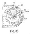
図82から図87を参照して、本発明の1つの態様による薬物送達システムのための駆動アセンブリ500が示される。駆動アセンブリ500は、作動ボタン506、容器508、針アクチュエータアセンブリ510、作動リリースまたはフリッパー512、リードねじ514、およびプランジャ516を含む。リードねじは、外部の半径方向に突出する翼520を備えるドラム部分518、および図84および図85に最もよく示され、および続いてより詳細に説明されるように、ねじ山部分(screw thread portion)522を含む。起動の前に、図83および図86に最もよく示されるように、作動リリース512の1つの端部513は、翼520のうちの1つと係合して、リードねじ514の回転を防止する。
Referring to FIGS. 82-87, a
1つの態様によると、図84から図86に示されるように、リードねじ514のねじ山部分522は、プランジャ516と接続されるナット524の内部ねじ山と係合し、別の態様によると、ナットおよびその内部ねじ山は、プランジャと一体的に単一構造として形成される。付加的に、定力ばね(constant force spring)526は、ドラム部分518内部に受け入れられ、およびリードねじ514を回転方向に付勢する。1つの態様によると、ばね526は、ベースカバー504に固定される。別の態様によると、図84から図86に示されるように、駆動アセンブリのハウジング528は、システム内部に配置され、およびばね526は、パワーパックのハウジング528に固定される。
According to one aspect, as shown in FIGS. 84-86, the threaded
その変位に比例する力プロファイルを有する圧縮ばねのようなつる巻ばねとは異なり、定力ばね526および同様のものは、長い作業長にわたって、比較的変化が少ないまたは一様な力プロファイルを維持する。一様な力プロファイルは、有利には、ばね力に比例する注射力を提供する。これは、変化が少ないまたは一様な注射力、およびしたがって、薬剤のための実質的に一定の注射速度を提供することとなる。ばね526は、図86において、2回転の材料のみを有するように示されるが、当業者は、より少ないまたは多い数の回転を採用することができることを理解するであろう。好ましくは、組み立てる人は、駆動アセンブリ500が組み立てられるときにばね526を巻き、およびばね526は、作動時まで、巻かれた状態に格納される。
Unlike a helical spring such as a compression spring having a force profile proportional to its displacement,
システムの作動に際して、針アクチュエータアセンブリ510は、リリースされて、付勢部材530の影響下で、軸方向に(図82から図85において右手に)、使用前状態から使用後状態に変位する(図83に最もよく示される。)。この変位の間、針アクチュエータアセンブリ510は、作動リリース512の第2の端部532に接触して圧迫し(bears against)、およびリリース512を反時計回りに回転させる。図87に示されるように、作動リリース512のこの反時計回りの回転は、その第1の端部513を翼520との係合から自由にする。翼520からの第1の端部513の係合解除に続いて、ばね526は、巻きがほどけおよびリードねじ514の回転を駆動し、これは、ナット524との組み合わせで、プランジャ514を前進させて、薬剤を分注する。
During operation of the system, the
リードねじ514が回転する際に、ハウジングにおける窓534を通して、ドラム部分518および翼520の回転を見ることができる。この窓534は、容器508内のストッパー536の直線運動を見ることよりもより明らかである方法で、ねじの進行を表示する。実際に、この回転運動は、直線運動よりも何倍も高精度である。当業者は、促進(advantage)または増加の正確な量は、リードねじ514のねじ山部分522のピッチ、ドラム部分518の直径、およびドラム部分518上の翼520の数に依存することを理解するであろう。
As the
図88から図93を参照して、本発明のさらなる態様による薬物送達システムのための駆動アセンブリ600が示される。駆動アセンブリ600は、ばねの力学的エネルギーを蓄え、および起動させられたときにそれを始動させるように働く。駆動アセンブリ600は、薬剤バレル601、バレル601内にスライド可能に配置されるストッパー602、第1のバルブプランジャ603、第2のバルブプランジャ604、第1の回転ナット(revolve nut)605、および第2の回転ナット606を含む。駆動アセンブリ600は、また、回転式表示器(rotary indicator)607、係止用要素(locking element)608、回転式表示器607内部に配置される定力ばね609、および作動リリースまたはフリッパー610も含む。駆動アセンブリ600は、薬物送達システムに組み立てられ得るハウジング611内部に、少なくとも部分的に配置される。
Referring to FIGS. 88-93, a
定力ばね609は、ハウジング611と回転式表示器607との間で回転式表示器607のドラム部分616の内部に含有される。駆動アセンブリの不活性状態(inactive state)は、ばね609を伸ばし(uncoilling)、およびこのエネルギーをハウジング611、回転式表示器607、および作動リリース610により幾何学的に利用することによって、エネルギーが印加されるようなものである。駆動アセンブリ600が不活性化されたとき、ばねは、後戻りし(recoils)および力学的エネルギーを回転式表示器の回転運動に変換する。
A
入れ子式マルチパートプランジャは、薬剤バレル601と回転式表示器607との間の力軸に沿って配向される。回転式表示器607は、ねじ山付きシャフト618を特徴とする。1つの態様によると、ねじ山は、複リード(dual lead)であり、および本質的に正方形または長方形である。マルチパート入れ子式プランジャは、ツーパートねじ山付きナット(第1の回転ナット605および第2の回転ナット606)およびツーパートプランジャ(第1のバルブプランジャ603および第2のバルブプランジャ604)を含む。第2の回転ナット606は、回転式表示器607および第1の回転ナット605と嵌合するねじ山付きシャフトであり、ならびにそれらと嵌合するためのその内面および外面(それぞれ、内部ねじ山および外部ねじ山)上の調和するねじ山(matching threads)を特徴とする。第2の回転ナット606は、また、第2のバルブプランジャ604上に底部を下げる(that bottoms down on)、その近位端上の円形カラー620(図92に最もよく示される。)を有する。第2の回転ナット606は、力軸に沿って自由にスピンする。第1の回転ナット605は、また、第2の回転ナット606と嵌合するための、第2の回転ナット606の外部ねじ山に対応するその内径上のねじ山を特徴とするねじ山付きシャフトである。
The telescoping multipart plunger is oriented along the force axis between the
1つの態様によると、1つの端部上に、第1の回転ナット605は、第1のバルブプランジャ603上に圧入して第1のバルブプランジャ603を第1の回転ナット605としっかりと(fixedly)接続する六角カラーを有する。駆動アセンブリ600において、第1の回転ナットは、自由に回転せず、およびパワーモジュールアセンブリが作動させられたときに、単に位置を変えることとなる。
According to one aspect, on one end, the first
第2のバルブプランジャ604は、その遠位端上の小さいカラー622、その近位端上の大きいカラー624、および大きい近位カラー624から突出する長いL字型アーム626(図93に最もよく示される。)を備える中空円筒状構成部品である。1つの実施形態によると、小さいカラー622は、断続的であり、ならびにカラーが屈曲しおよび第1のバルブプランジャ603と嵌合することを可能にする4つのリーフ片持ち梁式アームまたは板ばね623を特徴とする。第2のバルブプランジャ604の内面は、その近位端で大きいカラー624の半径方向内向きに突出する棚628を終端させる、その長さを通したアンダーカットを有する。棚628は、入れ子式アセンブリの内部で第2の回転ナット606と係合する。
The
第1のバルブプランジャ603は、ストッパー602に付着し、およびまた、第2のバルブプランジャ604と嵌合する中空円筒状構成部品である。より具体的には、第1のバルブプランジャ603は、ストッパー602と嵌合するために、その遠位端上の円筒状突起630を特徴とする。1つの態様によると、図89に最もよく示されるように、4つのスルースロット632は、第2のバルブプランジャ604の板ばねまたはアーム623および小さいカラー部分622と嵌合するために、第1のバルブプランジャ603の近位四分円上に配置される。第1および第2のバルブプランジャ603および604の両方は、自由にスライドする。
The
入れ子は、定力ばね609が後戻りしおよび回転式表示器607がスピンを開始するときに達成される。回転式表示器607と第2の回転ナット606との間の螺合取り付け(threaded attachment)は、第2の回転ナット606を回転させる。しかし、第2の回転ナット606は、第1の回転ナット605に螺合される(threaded)ので、これは回転することができずおよびバレル601内の薬剤によって引き起こされる圧力に起因して遠位並進に対する抵抗を受け、第2の回転ナット606は、近位に変位し、および第2のバルブプランジャの半径方向内向きに突出する棚628上において底部に達する(bottom out)こととなる。第2のバルブプランジャ604は、ハウジング611によって、近位に変位することが防止される。続いて、および回転式表示器607の継続する回転を伴って、第2の回転ナット606は、第1の回転ナット605(これは回転することができない)と螺合されるので、第1の回転ナット605は、遠位に位置を変えて、第1のバルブプランジャ603(およびストッパー602)を押して、バレル601から薬剤を分注する。
Nesting is achieved when the
第1のバルブプランジャ603は、小さいカラー部分622(第2のバルブプランジャ604の板ばねまたはアーム623の遠位端上にそれぞれ配置される)が第1のバルブプランジャ603のスロット632の対応する近位端と係合するまで、第2のバルブプランジャ604に対して遠位に変位する。これは第1および第2のバルブプランジャ603および604の相対位置を係止し、回転式表示器607の継続する回転を伴って、両方のバルブプランジャは、遠位に位置を変え、また同時に、第2の回転ナットを一緒に押す(棚624とのその近位係合のために)。
The
入れ子式プランジャの当初状態および最終状態、ならびにしたがって薬剤投与量は、回転式表示器607のねじ山付きシャフト618の長方形のねじ山形態、回転式表示器607のドラム部分616上のねじ山付きシャフト、および係止用要素608として作用する段付きピンによって制御される。1つの態様によると、回転式表示器607のドラム部分616上のねじ山付きシャフトは、単リード(single lead)であり、および入れ子式連鎖(chain)における構成部品の残りは複リードねじ山を有するので、他のねじ山付き構成部品の軸方向移動は、回転式表示器に対するロック608の軸方向移動の2倍である。
The initial and final states of the telescoping plunger, and thus the drug dose, is the rectangular thread form of the threaded
1つの実施形態によると、ロック608は、円筒状であり、ならびに1つの端部上のドーム型先端および他の端部上の円筒状カラーを特徴とする。回転式表示器のドラム部分616の外部上のねじ山は、ハウジング611の底部のスロットおよびアンダーカット636と共に、ロック608を所定の位置に捕捉し、それが力軸と平行にスライドすることを可能にする。したがって、ばね609がリリースされおよび回転式表示器607が回転する際に、ロック608は、同様に位置を変え、および回転式表示器のドラム部分616の外部上のねじ山の遠位端が到達したときに、凸の(positive)ストップを作り出す。
According to one embodiment, the
駆動アセンブリ600の態様の1つの利益は、定力ばね609の使用を含み、その力学的エネルギーは、バレル601内の薬剤に対する実質的に一定の直線力に変換される。次に、これは、均一の薬剤送達速度を生み出す。別の利益は、ねじ山形態によって駆動される入れ子式プランジャを採用することであり、駆動アセンブリは、他のプランジャ設計と比べて最大で0.75インチのインラインの空間節約を生み出すことができる。加えて、駆動アセンブリは、同一構成部品内部の当初のおよび最終の機械的拘束を通して、制御された薬剤投与量を提供する。
One benefit of aspects of
先述のように、他の薬物送達システムは、圧縮コイルばねを利用し、これは、ばねが広がるので最終的には減少する、最大限の力を作動時に及ぼす。プランジャにおいて減少する力は、可変の薬剤送達時間および薬剤放出(exit)圧力に変換する可能性がある。定力ばねを用いることによって、プランジャに及ぼされる力は、投薬の始めから終わりまで一定になる。加えて、薬物容器内側で位置を変える必要のある静的なプランジャの長さに加えてコイルばねが移動しなければならない距離は、長いアセンブリを作り出す可能性がある。対照的に、本発明の実施形態において、定力ばねは、半径方向に含まれ、及び起動の前または後に何ら付加的な空間を必要としない。さらに、入れ子式プランジャの態様は、プランジャの長さが、静的なプランジャの長さと比べて著しく低減され得ることを可能にする。 As mentioned earlier, other drug delivery systems make use of a compression coil spring, which exerts a maximum of force on actuation that eventually decreases as the spring expands. The decreasing force at the plunger can translate into variable drug delivery time and drug exit pressure. By using a constant force spring, the force exerted on the plunger is constant from the beginning to the end of the dosing. In addition, the distance that the coil spring must travel in addition to the length of the static plunger that needs to be repositioned inside the drug container can create a long assembly. In contrast, in embodiments of the present invention, constant force springs are included radially and do not require any additional space before or after activation. Furthermore, the aspect of the telescoping plunger allows the length of the plunger to be significantly reduced compared to the length of a static plunger.
以前の薬物送達システムは、機械的な構成部分は容器上に底部を下げる(bottoming down on)ことによって薬物送達が幾何学的形状依存を生み出すことを可能にするので、可変の投与量精度性能を有し、これをタイトな公差で作製することはできない。本発明のいくつかの実施形態は、回転表示器におけるねじ山形態および定力ばねの使用を介してプランジャの位置を変える開始および終了時間に対する制御を生み出す。 Previous drug delivery systems allow variable dose accuracy performance, as the mechanical components allow the drug delivery to create geometry dependency by bottoming down on the container. It can not be produced with tight tolerances. Some embodiments of the present invention create control over the start and end times of changing the position of the plunger through the use of thread forms and constant force springs in the rotary indicator.
駆動アセンブリは、薬物送達デバイスのために、十分に制御された時間、体積および圧力に加えて、空間を節約する幾何学的形状を作り出し、これは、より魅力的にコンパクトなおよび精密な薬物送達デバイスに位置を変える。 The drive assembly creates space-saving geometry in addition to well-controlled time, volume and pressure for drug delivery devices, which makes for more attractively compact and precise drug delivery Reposition to the device.
駆動アセンブリのいくつかの態様は、3つの回転するねじ山付きシャフト実施して、約0.75インチの直線状の空間の節約を作り出す。他の態様において、同一概念は、2つの回転するねじ山付きシャフトを用いて採用されおよび約0.5インチの空間の節約をもたらしてもよい。本発明のいくつかの態様は、定力ばねの回転エネルギーをプランジャの並進力の動き(translational force motion)に変換する。 Some aspects of the drive assembly implement three rotating threaded shafts to create a linear space savings of about 0.75 inches. In another aspect, the same concept may be employed with two rotating threaded shafts and provide space savings of about 0.5 inches. Some aspects of the invention convert rotational energy of a constant force spring into translational force motion of a plunger.
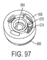
図94から図100を参照して、本発明のさらなる態様によるスペーサアセンブリ660が示される。スペーサアセンブリ660は、上述されおよび図76から図78に示されるスペーサアセンブリ460に類似し、ならびに同様の方法で動作して、同様の利点を獲得する。スペーサアセンブリ660は、固定式スペーサ666および調節可能スペーサ668を含む。固定式スペーサ666は、ストッパー462によって受け入れられラグ670がストッパー462と係合して固定式スペーサ666をストッパー462内部に固定するように構成されるが、ねじ山のような、他の適当な固定アレンジメントが利用されてもよい。固定式スペーサ666は、調節可能スペーサ668の外部ねじ山678を受け入れる内部ねじ山672を含む。固定式スペーサ666は、固定式スペーサ666のらせん部分上に位置付けられる複数の戻り止め674を含む。調節可能スペーサ668は、戻り止め674のうちの1つと係合するばね戻り止めアーム676を含んで、固定式スペーサ666に対する調節可能スペーサ668の回転および軸方向変位を防止する。ばね戻り止めアーム676は、戻り止め674を1つの方向に通り過ぎるように成形されおよび構成されて、固定式スペーサ666から離れる調節可能スペーサ668の回転および軸方向変位を可能にする。調節可能スペーサ668は、当初、ばね戻り止めアーム676の上部に力を加えることによってねじ山672、678を介して固定式スペーサ666に固定されていてもよく、これは、ばね戻り止めアーム676を戻り止め674から離れて付勢して、スペーサ666、668が互いに固定されることを可能にする。したがって、スペーサアセンブリ460と関連して上で論じられるのと同様の方法で、調節可能スペーサは、1つの軸方向に自由に回転して、スペーサアセンブリ660の長さを調節する。
Referring to FIGS. 94-100, a
再び図94から図100を参照して、スペーサアセンブリ660は、調節可能スペーサ668に受け入れられおよび固定されるように構成されたシム680をさらに含む。複数のサイズの調節可能スペーサ468、668を設けるよりも、複数のシム680サイズを提供して、容器14内部に複数の異なる充填体積を収容することができる。シム680は、スナップ嵌を用いる調節可能スペーサ668によって受け入れられるシム680から延びるコネクタ682を介して調節可能スペーサ668に固定されてもよいが、他の適当な固定アレンジメントが利用されてもよい。固定式スペーサ666の中心部分684は、調節可能スペーサ668が固定式スペーサ666に対して回転される間に係合されるように構成されて、調節可能スペーサ268に沿った固定式スペーサ666の回転を防止する。固定式スペーサ666の中心部分684は、シム680の開口を通してアクセス可能である。
Referring again to FIGS. 94-100,
1つの開示される態様の要素を、1つまたは複数の他の開示される態様の要素と組み合わせて異なる組み合わせを形成することができ、その全ては、本発明の範囲内であると見なされる。 Elements of one disclosed aspect may be combined with elements of one or more other disclosed aspects to form different combinations, all of which are considered to be within the scope of the present invention.
本開示は、例示的な設計を有するように記載されているが、開示を、本開示の精神および範囲内においてさらに修正することができる。本願は、したがって、開示の任意のバリエーション、使用、またはその一般的原理を用いる適応を対象とすることが意図される。さらに、本願は、本開示が関連する技術分野において知られているまたは慣習となっている実践内に入るような、および添付される特許請求の範囲の制限内にある、本開示からのそのような逸脱を対象とすることが意図される。 Although the present disclosure is described as having an exemplary design, the disclosure can be further modified within the spirit and scope of the present disclosure. This application is, therefore, intended to cover any variations, uses, or adaptations that use the general principles of the disclosure. Further, this application is intended to be within the scope of the appended claims, as falling within the practice known or customary in the relevant technical field to which this disclosure relates. It is intended to target the
方法は、第1のばねを提供する工程、内側ばねの遠位端の周囲に配置される第1のプランジャ部材を提供する工程、第1のプランジャ部材の周囲に配置される第2のプランジャを提供する工程、前記第1のプランジャ部材と前記第2のプランジャとの間に第2のばねを提供する工程、をさらに含む。 The method includes the steps of providing a first spring, providing a first plunger member disposed around the distal end of the inner spring, the second plunger is disposed around the first plunger member And providing a second spring between the first plunger member and the second plunger.
図17から図26を参照して、駆動アセンブリ12は、第1のプランジャ部材52、第1のプランジャ部材52によって受け入れられる第2のプランジャ部材54、第1の付勢部材56、第2の付勢部材58、プランジャ作動部材60、およびインデックス部材62を含む。第1のプランジャ部材52は、使用前状態(図18に示される)から、使用状態(図19に示される)まで、使用後状態(図20に示される)まで、移動可能であり、第1のプランジャ部材52は、スペーサアセンブリ40と係合しおよび容器14内部においてストッパー34を移動させて容器14から薬剤を分注するように構成される。第1のプランジャ部材52は、軸方向に移動するように構成される。第2のプランジャ部材54および第1のプランジャ部材52は、入れ子式(telescoping)アレンジメントを形成し、第2のプランジャ部材54は、第1のプランジャ部材52が所定の軸方向距離移動した後に軸方向に移動するように構成される。第1および第2のプランジャ部材52、54の移動は、第1および第2の付勢部材56、58によって提供され、これは圧縮ばねであるが、付勢部材56、58のための他の適当なアレンジメントが利用されてもよい。
Referring to FIGS. 17-26, the
第1の付勢部材56は、第2のプランジャ部材54によって受け入れられ、およびプランジャ作動部材60(およびインデックス部材62)と第2のプランジャ部材54の第1のばね座64との間に拘束される。第2の付勢部材58は、第1の付勢部材56から半径方向内向きに位置付けられ、および第2のプランジャ部材54によって受け入れられる。第2の付勢部材58は、第2のプランジャ部材54の第2のばね座66と第1のプランジャ部材52との間に拘束される。第2の付勢部材58は、第1のプランジャ52部材を、容器14に向かって使用前状態から使用状態におよび使用後状態に付勢するように構成される。第1の付勢部材56は、第2のプランジャ部材54を容器14に向かって付勢するように構成され、これは、次に、第1のプランジャ部材52を容器14に向かって使用前状態から使用状態におよび使用後状態に付勢する。より具体的には、第2の付勢部材58は、第1のプランジャ部材52をスペーサアセンブリ40またはストッパー34に対抗して駆動して容器14をバルブアセンブリ16内に係合するように移動させ、それによって容器14のクロージャ36を貫通しおよび容器14を針28と流体連通して配置するように構成される。第1の付勢部材56は、容器14内部においてストッパー34を移動させて容器14内部の薬剤を分注するように構成される。第2の付勢部材58は、第1の付勢部材56とは異なるばね定数を有する。具体的には、第2の付勢部材58は、第1の付勢部材56より硬くて容器14のクロージャ36を貫通するための高い力を提供し、一方、第1の付勢部材56は容器14内部の流体または薬剤の粘度に適当であるような分注するためのより低い力を提供する。
The first biasing member 56 is received by the
図18および図23に示されるように、プランジャ作動部材60の第1の回転状態において、複数の突出部80および複数のスロットまたはカットアウト81は、プランジャ作動部材60が第1のプランジャ部材52と係合するように、整列しておらず(out of alignment)、第1および第2の付勢部材56、58が第1および第2のプランジャ部材52、54をプランジャ作動部材60から離れて付勢する状態で、第1および第2のプランジャ部材52、54の移動を防止する。図19および図24に示されるように、プランジャ作動部材60の第2の回転状態において、複数の突出部80および複数のスロットまたはカットアウト81は、プランジャ作動部材60が第1のプランジャ部材52から係合解除されて第1および第2のプランジャ部材52、54の移動を可能にし、それによって容器14からの分注プロセスを開始するように、互いに整列している。
As shown in FIGS. 18 and 23, in the first rotational state of the
ユーザーがユーザーインターフェース部288を遠位にスライドさせる際に、ボタンばね284の中央ばねアーム302は、ハウジング20上のばねアーム圧迫面306を乗り越え(rides over)、一方、第1および第2の圧迫面298、300は、ハウジング20上の第1および第2の圧迫ランプ308、310と係合する。ボタンばね284上の力は、ばねアーム圧迫面306および第1および第2の圧迫ランプ308、310との係合を通してバランスがとられて、アクチュエータボタン26の滑らかな軸方向変位またはスライドが提供される。
As the user slides the
図70Fは、内側プランジャ404の近位フランジ402が外側プランジャ406の内部肩部410と接触したときの薬剤送達の終わりを示し、それによって、薬剤バレル412に対する内側プランジャ404(およびストッパースペーサ14およびストッパー422)の変位を終え、および薬剤の流れを止める。
Figure 70F shows the end proximal flange 402 of the
図74および図75を参照して、本発明の1つの態様による制限部材452は、駆動アセンブリと共に配置される。制限部材452は、薬剤投与量の完了に続いて、針アクチュエータ本体96、220の最終変位のタイミングを支配する。固定されたポスト周りの回転の代わりに、制限部材452は、自由に浮動する(floats)。プランジャが、ギャップのために十分に遠位に変位して制限部材452と位置合わせすると(図74および図75に示されるように)、制限部材452は、針アクチュエータ本体96、220および針アクチュエータ本体(図75に最もよく示される。)と係合する制限部材174のアームの後方の角度が付いた面454に掛かるばねの力のために、ギャップ内に横方向に変位する。制限部材が針アクチュエータ本体96、220をもはや保持しなくなると、針アクチュエータ本体96、220は、使用後状態への軸方向移動を完了することが自由になる。さらに、図75に示されるように、制限部材452は、容器14のバレル部分の後方上に付勢され、これは、さまざまな構成部分の公差連鎖を最小限にしおよび投与量精度を向上させる。
Referring to FIGS. 74 and 75, the limiting
図81Bは、薬剤バレルの近位部においてストッパー494の近位凹部内部に配備された自動調節スペーサのキャップを示す。ベース柱482は、中空キャップ484内に組み立てられ、ベース部488は、ストッパー494と係合し、および足部498は、バレルの近位端の外側に配置される。
FIG. 81B shows the cap of the self-adjusting spacer deployed within the proximal recess of
第1のバルブプランジャ603は、小さいカラー部分622(第2のバルブプランジャ604の板ばねまたはアーム623の遠位端上にそれぞれ配置される)が第1のバルブプランジャ603のスロット632の対応する近位端と係合するまで、第2のバルブプランジャ604に対して遠位に変位する。これは第1および第2のバルブプランジャ603および604の相対位置を係止し、回転式表示器607の継続する回転を伴って、両方のバルブプランジャは、遠位に位置を変え、また同時に、第2の回転ナットを一緒に押す(棚628とのその近位係合のために)。
The
Claims (28)
ハウジング、
薬剤を受け入れるように構成された容器であって、前記容器は前記容器内部において移動するように構成されたストッパーおよびクロージャを含む、容器、
前記容器と流体連通する針、
前記ストッパーと係合するように構成されたスペーサ、
第1のプランジャ、
前記第1のプランジャを軸方向に付勢するように構成された第1のばね、
前記第1のプランジャの周囲に配置される第2のプランジャ、および
前記第2のプランジャを軸方向に付勢するように構成された第2のばね、
を含み、
前記第1のプランジャは、前記第1のばねを介して前記ハウジングに対して前記スペーサおよび前記容器を移動させるように構成され、
および
前記第2のプランジャは、前記第2のばねを介して前記容器に対して前記スペーサおよび前記ストッパーを移動させるように構成されることを特徴とするシステム。 A drug delivery system for injecting a drug, said system comprising
housing,
A container configured to receive a medicament, the container including a stopper and a closure configured to move inside the container,
A needle in fluid communication with the container,
A spacer configured to engage with the stopper,
First plunger,
A first spring configured to axially bias said first plunger,
A second plunger disposed about the first plunger, and a second spring configured to axially bias the second plunger,
Including
The first plunger is configured to move the spacer and the container relative to the housing via the first spring,
And the second plunger is configured to move the spacer and the stopper relative to the container via the second spring.
前記スペーサを前記容器内に挿入する工程、および
前記スペーサを備える前記薬剤容器を薬剤送達デバイス内に装填する工程、
を含むことを特徴とする薬物送達デバイスを組み立てる方法。 Selecting from the differently sized spacers a spacer which occupies a space from the proximal end of the stopper placed in the drug container to the proximal end of the container;
Inserting the spacer into the container, and loading the drug container comprising the spacer into a drug delivery device;
A method of assembling a drug delivery device comprising:
前記内側ばねの遠位端の周囲に配置される第1のプランジャを提供する工程、
前記第1のプランジャの周囲に配置される第2のプランジャを提供する工程、および
前記第1のプランジャ部材と前記第2のプランジャとの間に配置される第2のばねを提供する工程、
をさらに含むことを特徴とする請求項9に記載の方法。 Providing a first spring,
Providing a first plunger disposed around the distal end of the inner spring;
Providing a second plunger disposed about the first plunger; and providing a second spring disposed between the first plunger member and the second plunger.
The method of claim 9, further comprising:
第1のプランジャ、
前記第1のプランジャを軸方向に付勢するように構成された第1のばね、
前記第1のプランジャの周囲に配置される第2のプランジャであって、前記第2のプランジャは外側プランジャ部材および内側プランジャ部材を含み、前記内側プランジャ部材の少なくとも一部は前記外側プランジャ部材の内部に受け入れられ、前記外側プランジャ部材は前記外側プランジャ部材に対する前記内側プランジャ部材の所定の軸方向変位に際して前記内側プランジャ部材の突出部と係合するように構成された突出部を有する、第2のプランジャ、ならびに
前記第2のプランジャの前記内側プランジャ部材を軸方向に付勢するように構成された第2のばね、
を含むことを特徴とする駆動アセンブリ。 A drive assembly for a drug delivery system, said drive assembly comprising:
First plunger,
A first spring configured to axially bias said first plunger,
A second plunger disposed about the first plunger, the second plunger including an outer plunger member and an inner plunger member, at least a portion of the inner plunger member being an interior of the outer plunger member A second plunger, the outer plunger member having a projection adapted to engage with the projection of the inner plunger member upon predetermined axial displacement of the inner plunger member relative to the outer plunger member; And a second spring configured to axially bias the inner plunger member of the second plunger,
And a drive assembly characterized in that.
容器内部においてストッパーと係合しおよびストッパーを移動させるように構成されたプランジャ部材であって、第1の状態および前記第1の状態から軸方向に間隔が空けられた第2の状態を有する、プランジャ部材、
前記プランジャ部材を前記第1の状態から前記第2の状態に移動させるように構成された付勢部材、および
前記プランジャ部材に対して回転可能なプランジャ作動部材であって、前記プランジャ部材が前記プランジャ作動部材に対して軸方向に固定される第1の回転状態および前記プランジャ部材が前記プランジャ作動部材に対して軸方向に移動可能である第2の回転状態を有する、プランジャ作動部材、
を含むことを特徴とする駆動アセンブリ。 A drive assembly for a drug delivery system, said drive assembly comprising:
A plunger member configured to engage and move a stopper within a container, the plunger having a first state and a second state axially spaced from the first state. Plunger member,
A biasing member configured to move the plunger member from the first state to the second state; and a plunger actuating member rotatable relative to the plunger member, wherein the plunger member is the plunger A plunger actuating member having a first rotational state axially fixed relative to the actuating member and a second rotational state in which the plunger member is axially movable relative to the plunger actuating member;
And a drive assembly characterized in that.
薬剤を受け入れるように構成された容器であって、前記容器は前記容器内部において移動するように構成されたストッパーおよびクロージャを含む、容器、
駆動アセンブリであって、
前記容器内部において前記ストッパーを移動させるように構成されたプランジャ部材であって、前記プランジャ部材は第1の状態および前記第1の状態から軸方向に間隔が空けられた第2の状態を有する、プランジャ部材、
前記プランジャ部材を前記第1の状態から前記第2の状態に移動させるように構成された付勢部材、および
前記プランジャ部材に対して回転可能なプランジャ作動部材であって、前記プランジャ作動部材は、前記プランジャ部材が前記プランジャ作動部材に対して軸方向に固定される第1の回転状態および前記プランジャ部材が前記プランジャ作動部材に対して軸方向に回転可能である第2の回転状態を有する、プランジャ作動部材、
を含む、駆動アセンブリ、ならびに
前記容器と流体連通して配置されるように構成された針を含む針アクチュエータアセンブリであって、前記針は第1の状態および前記第1の状態から間隔が空けられた第2の状態から移動可能である、針アクチュエータアセンブリ、
を含み、
前記針アクチュエータの一部は、前記プランジャ作動部材と係合して前記プランジャ作動部材を前記第1の回転状態から前記第2の回転状態に移動させるように構成されることを特徴とするシステム。 A drug delivery system for injecting a drug, said system comprising
A container configured to receive a medicament, the container including a stopper and a closure configured to move inside the container,
A drive assembly,
A plunger member configured to move the stopper within the container, the plunger member having a first state and a second state axially spaced from the first state. Plunger member,
A biasing member configured to move the plunger member from the first state to the second state; and a plunger actuating member rotatable relative to the plunger member, the plunger actuating member being A plunger having a first rotational state in which the plunger member is axially fixed relative to the plunger actuating member, and a second rotational state in which the plunger member is axially rotatable relative to the plunger actuating member Operating member,
A needle actuator assembly including a drive assembly and a needle configured to be disposed in fluid communication with the container, the needle being spaced apart from a first state and the first state A needle actuator assembly movable from a second state,
Including
A system characterized in that a portion of the needle actuator is configured to engage the plunger actuating member to move the plunger actuating member from the first rotational state to the second rotational state.
薬剤を受け入れるように構成された容器であって、前記容器は前記容器内部において移動するように構成されたストッパーおよびクロージャを含む、容器、
駆動アセンブリであって、
前記容器内部において前記ストッパーを移動させるように構成されたプランジャ部材であって、前記プランジャ部材は第1の状態および前記第1の状態から軸方向に間隔が空けられた第2の状態を有し、前記プランジャ部材は複数のコード化された突出部を画定する、プランジャ部材、
前記プランジャ部材を前記第1の状態から前記第2の状態に移動させるように構成された付勢部材、および
前記プランジャ部材に対して移動可能なプランジャ作動部材であって、前記プランジャ作動部材は、前記プランジャ部材が前記プランジャ作動部材に対して軸方向に固定される第1の状態および前記プランジャ部材が前記プランジャ作動部材に対して軸方向に回転可能である第2の状態を有する、プランジャ作動部材
を含む、駆動アセンブリ、
前記容器と流体連通して配置されるように構成された針を含む針アクチュエータアセンブリであって、前記針は第1の状態および前記第1の状態から間隔が空けられた第2の状態から移動可能であり、前記針アクチュエータの一部は前記プランジャ作動部材と係合して前記プランジャ作動部材を前記第1の状態から前記第2の状態に移動させるように構成される、針アクチュエータアセンブリ、
前記複数のコード化された突出部のうちの1つと位置合わせされおよび前記複数のコード化された突出部のうちの1つと係合するように構成されて針アクチュエータアセンブリの移動を制限する制限部材、ならびに
前記容器の前記ストッパーと係合しおよび前記プランジャ部材と係合するように構成されたスペーサアセンブリ、
を含むことを特徴とするシステム。 A drug delivery system for injecting a drug, said system comprising
A container configured to receive a medicament, the container including a stopper and a closure configured to move inside the container,
A drive assembly,
A plunger member configured to move the stopper within the container, the plunger member having a first state and a second state axially spaced from the first state. A plunger member defining a plurality of coded projections;
A biasing member configured to move the plunger member from the first state to the second state; and a plunger actuating member movable with respect to the plunger member, the plunger actuating member being A plunger actuating member having a first state in which the plunger member is axially fixed relative to the plunger actuating member and a second state in which the plunger member is axially rotatable relative to the plunger actuating member Drive assembly, including
A needle actuator assembly including a needle configured to be disposed in fluid communication with the container, the needle moving from a first state and a second state spaced from the first state A needle actuator assembly, wherein a portion of the needle actuator is configured to engage the plunger actuating member to move the plunger actuating member from the first state to the second state;
A restriction member aligned with one of the plurality of coded projections and configured to engage with one of the plurality of coded projections to limit movement of the needle actuator assembly And a spacer assembly configured to engage with the stopper of the container and engage with the plunger member;
A system characterized by including.
Priority Applications (1)
| Application Number | Priority Date | Filing Date | Title |
|---|---|---|---|
| JP2020126810A JP7510812B2 (en) | 2016-06-09 | 2020-07-27 | Drive assembly and spacer for drug delivery system - Patents.com |
Applications Claiming Priority (5)
| Application Number | Priority Date | Filing Date | Title |
|---|---|---|---|
| US201662347948P | 2016-06-09 | 2016-06-09 | |
| US62/347,948 | 2016-06-09 | ||
| US15/616,250 | 2017-06-07 | ||
| US15/616,250 US10792432B2 (en) | 2016-06-09 | 2017-06-07 | Drive assembly and spacer for drug delivery system |
| PCT/US2017/036572 WO2017214409A1 (en) | 2016-06-09 | 2017-06-08 | Drive assembly and spacer for drug delivery system |
Related Child Applications (1)
| Application Number | Title | Priority Date | Filing Date |
|---|---|---|---|
| JP2020126810A Division JP7510812B2 (en) | 2016-06-09 | 2020-07-27 | Drive assembly and spacer for drug delivery system - Patents.com |
Publications (2)
| Publication Number | Publication Date |
|---|---|
| JP2019517358A true JP2019517358A (en) | 2019-06-24 |
| JP6741794B2 JP6741794B2 (en) | 2020-08-19 |
Family
ID=60572134
Family Applications (4)
| Application Number | Title | Priority Date | Filing Date |
|---|---|---|---|
| JP2018564790A Active JP6741794B2 (en) | 2016-06-09 | 2017-06-08 | Drive assembly and spacer for drug delivery system |
| JP2020126810A Active JP7510812B2 (en) | 2016-06-09 | 2020-07-27 | Drive assembly and spacer for drug delivery system - Patents.com |
| JP2022121559A Pending JP2022136294A (en) | 2016-06-09 | 2022-07-29 | Drive assemblies and spacers for drug delivery systems |
| JP2024153984A Pending JP2024170570A (en) | 2016-06-09 | 2024-09-06 | DRIVE ASSEMBLY AND SPACER FOR A DRUG DELIVERY SYSTEM - Patent application |
Family Applications After (3)
| Application Number | Title | Priority Date | Filing Date |
|---|---|---|---|
| JP2020126810A Active JP7510812B2 (en) | 2016-06-09 | 2020-07-27 | Drive assembly and spacer for drug delivery system - Patents.com |
| JP2022121559A Pending JP2022136294A (en) | 2016-06-09 | 2022-07-29 | Drive assemblies and spacers for drug delivery systems |
| JP2024153984A Pending JP2024170570A (en) | 2016-06-09 | 2024-09-06 | DRIVE ASSEMBLY AND SPACER FOR A DRUG DELIVERY SYSTEM - Patent application |
Country Status (10)
| Country | Link |
|---|---|
| US (3) | US10792432B2 (en) |
| EP (1) | EP3468644A1 (en) |
| JP (4) | JP6741794B2 (en) |
| CN (3) | CN109475688B (en) |
| AU (3) | AU2017277770C1 (en) |
| BR (2) | BR112018075437B1 (en) |
| CA (2) | CA3027183C (en) |
| MX (2) | MX2018015312A (en) |
| RU (1) | RU2740732C2 (en) |
| WO (1) | WO2017214409A1 (en) |
Families Citing this family (19)
| Publication number | Priority date | Publication date | Assignee | Title |
|---|---|---|---|---|
| US8157769B2 (en) | 2009-09-15 | 2012-04-17 | Medimop Medical Projects Ltd. | Cartridge insertion assembly for drug delivery system |
| US9421323B2 (en) | 2013-01-03 | 2016-08-23 | Medimop Medical Projects Ltd. | Door and doorstop for portable one use drug delivery apparatus |
| IL295010B2 (en) | 2015-03-10 | 2025-10-01 | Regeneron Pharma | Aseptic piercing system and method |
| EP4252798A3 (en) | 2015-06-04 | 2023-10-25 | Medimop Medical Projects Ltd. | Cartridge insertion for drug delivery device |
| JP6957525B2 (en) | 2016-06-02 | 2021-11-02 | ウェスト ファーマ サービシーズ イスラエル リミテッド | Needle evacuation by 3 positions |
| US10792432B2 (en) * | 2016-06-09 | 2020-10-06 | Becton, Dickinson And Company | Drive assembly and spacer for drug delivery system |
| CN109562220B (en) | 2016-08-01 | 2021-06-29 | 西医药服务以色列有限公司 | Partial door closing prevents spring |
| US11547801B2 (en) | 2017-05-05 | 2023-01-10 | Regeneron Pharmaceuticals, Inc. | Auto-injector |
| JP6921997B2 (en) | 2017-05-30 | 2021-08-18 | ウェスト ファーマ サービシーズ イスラエル リミテッド | Modular drive train for wearable syringes |
| JP7402799B2 (en) | 2017-12-22 | 2023-12-21 | ウェスト ファーマ サービシーズ イスラエル リミテッド | Syringes available with different cartridge sizes |
| US12023463B2 (en) | 2018-01-02 | 2024-07-02 | Cerner Innovation, Inc. | Clinical notifications |
| JOP20200220A1 (en) | 2018-03-13 | 2020-09-07 | Coalesce Product Development Ltd | Devices for injecting drugs and methods of use |
| CN112188906B (en) | 2018-05-24 | 2023-10-27 | 诺华股份有限公司 | Automatic drug delivery device |
| EP3603700A1 (en) | 2018-07-30 | 2020-02-05 | Tecpharma Licensing AG | Needle insertion and retraction mechanism |
| GB2581514A (en) * | 2019-02-22 | 2020-08-26 | Danby Medical Ltd | Infusion Pump |
| CN114247014B (en) * | 2020-09-25 | 2024-12-24 | 群康生技股份有限公司 | syringe |
| US20230405230A1 (en) * | 2020-11-19 | 2023-12-21 | Becton, Dickinson And Company | Drug Delivery Device with Container Holder |
| USD1007676S1 (en) | 2021-11-16 | 2023-12-12 | Regeneron Pharmaceuticals, Inc. | Wearable autoinjector |
| US20240165376A1 (en) * | 2022-11-23 | 2024-05-23 | Altek Biotechnology Corporation | Medical insertion mechanism and medical device therewith |
Citations (5)
| Publication number | Priority date | Publication date | Assignee | Title |
|---|---|---|---|---|
| JP2008522751A (en) * | 2004-12-09 | 2008-07-03 | ウェスト ファーマシューティカル サービシズ インコーポレイテッド | Automatic injection and retraction syringe |
| WO2012032411A2 (en) * | 2010-09-07 | 2012-03-15 | Tecpharma Licensing Ag | Automatic injection device |
| JP2014500090A (en) * | 2010-12-02 | 2014-01-09 | オーバル メディカル テクノロジーズ リミテッド | Self-injection delivery mechanism |
| JP2014533565A (en) * | 2011-11-24 | 2014-12-15 | サノフィ−アベンティス・ドイチュラント・ゲゼルシャフト・ミット・ベシュレンクテル・ハフツング | Automatic syringe |
| JP2017533767A (en) * | 2014-11-12 | 2017-11-16 | ノボ・ノルデイスク・エー/エス | Method for manufacturing one of a range of automatic injectors |
Family Cites Families (104)
| Publication number | Priority date | Publication date | Assignee | Title |
|---|---|---|---|---|
| BE755224A (en) * | 1969-08-25 | 1971-02-24 | Philips Nv | INJECTION SYRINGE |
| GB9607549D0 (en) | 1996-04-11 | 1996-06-12 | Weston Medical Ltd | Spring-powered dispensing device |
| CH692543A5 (en) | 1997-09-25 | 2002-07-31 | Disetronic Licensing Ag | Dispenser with auto switch. |
| DE19821933C1 (en) | 1998-05-15 | 1999-11-11 | Disetronic Licensing Ag | Device for administering an injectable product |
| SE9803662D0 (en) | 1998-10-26 | 1998-10-26 | Pharmacia & Upjohn Ab | autoinjector |
| DE10018924C2 (en) | 2000-04-17 | 2002-07-18 | Disetronic Licensing Ag | Device for the dosed administration of an injectable product |
| US6517517B1 (en) | 2000-06-08 | 2003-02-11 | Mayo Foundation For Medical Education And Research | Automated injection device for administration of liquid medicament |
| US8034026B2 (en) | 2001-05-18 | 2011-10-11 | Deka Products Limited Partnership | Infusion pump assembly |
| DE10163327A1 (en) | 2001-07-30 | 2003-02-27 | Disetronic Licensing Ag | Reservoir module with piston rod |
| GB2421689B (en) | 2002-08-05 | 2007-03-07 | Caretek Medical Ltd | Drug delivery system |
| CN1723053A (en) | 2002-09-12 | 2006-01-18 | 儿童医院医疗中心 | Method and device for painless injection of medication |
| DE10342059B4 (en) | 2003-09-11 | 2007-03-01 | Tecpharma Licensing Ag | Delivery device with piercing and Ausschutinrichtung |
| IL157981A (en) | 2003-09-17 | 2014-01-30 | Elcam Medical Agricultural Cooperative Ass Ltd | Auto-injector |
| DE10351594A1 (en) | 2003-11-05 | 2005-06-16 | Tecpharma Licensing Ag | Device for the administration of an injectable product |
| US7670314B2 (en) | 2004-02-17 | 2010-03-02 | Children's Hospital Medical Center | Injection device for administering a vaccine |
| GB2414404B (en) | 2004-05-28 | 2009-06-03 | Cilag Ag Int | Injection device |
| GB2414403B (en) | 2004-05-28 | 2009-01-07 | Cilag Ag Int | Injection device |
| GB2414399B (en) | 2004-05-28 | 2008-12-31 | Cilag Ag Int | Injection device |
| CA3015269A1 (en) | 2004-11-22 | 2006-06-01 | Kaleo, Inc. | Devices, systems, and methods for medicament delivery |
| US7648483B2 (en) | 2004-11-22 | 2010-01-19 | Intelliject, Inc. | Devices, systems and methods for medicament delivery |
| US7648482B2 (en) | 2004-11-22 | 2010-01-19 | Intelliject, Inc. | Devices, systems, and methods for medicament delivery |
| DE102004063644A1 (en) | 2004-12-31 | 2006-07-20 | Tecpharma Licensing Ag | Device for the dosed administration of a fluid product with torsion spring drive |
| DE102005017477A1 (en) | 2005-02-18 | 2006-08-31 | Tecpharma Licensing Ag | Spring in or for an injection device |
| WO2006096901A1 (en) * | 2005-03-14 | 2006-09-21 | Global Medisafe Holdings Limited | Exchange needle auto retractable syringe |
| AU2007212269B2 (en) | 2006-02-09 | 2013-03-28 | Deka Products Limited Partnership | Fluid delivery systems and methods |
| CN101438327B (en) * | 2006-03-29 | 2013-11-06 | 因特利杰克特有限公司 | Devices, systems and methods for medicament delivery |
| DK2099434T3 (en) * | 2006-11-21 | 2019-08-12 | Kaleo Inc | DEVICES AND SYSTEMS FOR MEDICINAL ADMINISTRATION |
| WO2008098246A1 (en) | 2007-02-09 | 2008-08-14 | Deka Products Limited Partnership | Automated insertion assembly |
| US8323250B2 (en) | 2007-04-30 | 2012-12-04 | Medtronic Minimed, Inc. | Adhesive patch systems and methods |
| WO2009007229A1 (en) | 2007-07-06 | 2009-01-15 | Shl Medical Ab | One shot injector with dual springs |
| ES2715604T3 (en) | 2007-07-20 | 2019-06-05 | Hoffmann La Roche | Manual portable infusion device |
| US8226606B2 (en) | 2007-09-28 | 2012-07-24 | Calibra Medical, Inc. | Disposable infusion device with tactile dosage volume indicator |
| US9345836B2 (en) | 2007-10-02 | 2016-05-24 | Medimop Medical Projects Ltd. | Disengagement resistant telescoping assembly and unidirectional method of assembly for such |
| US7967795B1 (en) | 2010-01-19 | 2011-06-28 | Lamodel Ltd. | Cartridge interface assembly with driving plunger |
| US8313467B2 (en) | 2007-12-27 | 2012-11-20 | Medtronic Minimed, Inc. | Reservoir pressure equalization systems and methods |
| WO2009103759A1 (en) | 2008-02-20 | 2009-08-27 | Unomedical A/S | Insertion device with horizontally moving part |
| US7927306B2 (en) | 2008-06-26 | 2011-04-19 | Calibra Medical, Inc. | Disposable infusion device with prime indicator |
| EP2384217B1 (en) | 2008-12-22 | 2021-01-27 | Unomedical A/S | Medical device comprising adhesive pad |
| JP5619029B2 (en) | 2009-01-30 | 2014-11-05 | ネステク ソシエテ アノニム | Infusion pump cassette with free flow prevention valve mechanism |
| AU2010208447B2 (en) | 2009-01-30 | 2015-11-05 | Nestec S.A. | Infusion pump cassette with anti-free-flow valve mechanism |
| RU2012102384A (en) | 2009-06-25 | 2013-07-27 | Нестек С.А. | CAPTURE CLAMP ASSEMBLY FOR INFUSION CASSETTE |
| US10071198B2 (en) | 2012-11-02 | 2018-09-11 | West Pharma. Servicees IL, Ltd. | Adhesive structure for medical device |
| CA2936768C (en) | 2009-10-13 | 2019-01-08 | Valeritas, Inc. | Fluid delivery device |
| US8449504B2 (en) | 2009-11-11 | 2013-05-28 | Calibra Medical, Inc. | Wearable infusion device and system |
| US8998858B2 (en) | 2009-12-29 | 2015-04-07 | Medtronic Minimed, Inc. | Alignment and connection systems and methods |
| US8348898B2 (en) | 2010-01-19 | 2013-01-08 | Medimop Medical Projects Ltd. | Automatic needle for drug pump |
| DE102010001506A1 (en) | 2010-02-02 | 2011-08-04 | Vosseler, Michael, 78073 | Dermal access device |
| ES2484266T3 (en) | 2010-03-01 | 2014-08-11 | Eli Lilly And Company | Automatic injection device with delay mechanism including a double function thrust element |
| NZ602782A (en) | 2010-04-21 | 2015-07-31 | Abbvie Biotechnology Ltd | Wearable automatic injection device for controlled delivery of therapeutic agents |
| PT2575935E (en) | 2010-06-07 | 2015-10-20 | Amgen Inc | Drug delivery device |
| EP2579919B1 (en) | 2010-06-09 | 2020-09-02 | Zealand Pharma A/S | Fluid delivery device |
| CA2801636A1 (en) | 2010-06-11 | 2011-12-15 | Sanofi-Aventis Deutschland Gmbh | Drive assembly, drive component and drug delivery device |
| EP2608825B1 (en) | 2010-08-27 | 2014-08-13 | Novo Nordisk A/S | Medical injection device |
| US8915879B2 (en) | 2010-09-24 | 2014-12-23 | Perqflo, Llc | Infusion pumps |
| EP2438945A1 (en) | 2010-10-08 | 2012-04-11 | Sanofi-Aventis Deutschland GmbH | Reusable engine for an auto-injector |
| US8668675B2 (en) | 2010-11-03 | 2014-03-11 | Flugen, Inc. | Wearable drug delivery device having spring drive and sliding actuation mechanism |
| EP2468333A1 (en) * | 2010-12-21 | 2012-06-27 | Sanofi-Aventis Deutschland GmbH | Auto-injector |
| GB201021777D0 (en) | 2010-12-22 | 2011-02-02 | Owen Mumford Ltd | Autoinjectors |
| GB2486693B (en) | 2010-12-22 | 2016-05-18 | Owen Mumford Ltd | Autoinjectors and manufacturing systems thereof |
| US8939943B2 (en) | 2011-01-26 | 2015-01-27 | Kaleo, Inc. | Medicament delivery device for administration of opioid antagonists including formulations for naloxone |
| EP2489386A1 (en) * | 2011-02-18 | 2012-08-22 | Sanofi-Aventis Deutschland GmbH | Auto-injector |
| US9283318B2 (en) | 2011-02-22 | 2016-03-15 | Medtronic Minimed, Inc. | Flanged sealing element and needle guide pin assembly for a fluid infusion device having a needled fluid reservoir |
| US8469933B2 (en) | 2011-03-18 | 2013-06-25 | Zyno Medical Llc | Pump activated pinch clamp |
| DK2510960T3 (en) | 2011-04-12 | 2017-09-18 | Hoffmann La Roche | Infusion pump device with cylinder piston metering unit and optical piston position detection |
| MX345747B (en) | 2011-04-21 | 2017-02-14 | Abbvie Inc | Wearable automatic injection device. |
| US8496619B2 (en) | 2011-07-15 | 2013-07-30 | Antares Pharma, Inc. | Injection device with cammed ram assembly |
| US9707335B2 (en) | 2011-09-02 | 2017-07-18 | Unitract Syringe Pty Ltd | Drive mechanism for drug delivery pumps with integrated status indication |
| WO2013033467A2 (en) | 2011-09-02 | 2013-03-07 | Unitract Syringe Pty Ltd | Drive mechanism for drug delivery pumps with integrated status indication |
| US9814832B2 (en) | 2011-09-02 | 2017-11-14 | Unl Holdings Llc | Drive mechanism for drug delivery pumps with integrated status indication |
| ITFI20110194A1 (en) | 2011-09-08 | 2013-03-09 | Menarini Int Operations Lu Sa | MEDICINE DOSES SELF-INJECTION DEVICE |
| AU2012308764C1 (en) | 2011-09-13 | 2017-05-25 | Unitract Syringe Pty Ltd | Sterile fluid pathway connection to drug containers for drug delivery pumps |
| CA2849797A1 (en) | 2011-09-22 | 2013-03-28 | Abbvie Inc. | Automatic injection device |
| MX2014003528A (en) | 2011-09-22 | 2014-12-05 | Abbvie Inc | Automatic injection device. |
| DK2819724T3 (en) | 2012-02-27 | 2019-05-27 | Hoffmann La Roche | Spring force assembly for pre-tensioning or activating plugs in syringes, cartridges for injection pens and the like |
| US11033679B2 (en) | 2012-03-12 | 2021-06-15 | Unl Holdings Llc | Fill-finish cartridges for sterile fluid pathway assemblies and drug delivery devices incorporating fill-finish cartridges |
| US9463280B2 (en) | 2012-03-26 | 2016-10-11 | Medimop Medical Projects Ltd. | Motion activated septum puncturing drug delivery device |
| CN104379192B (en) | 2012-04-13 | 2018-11-09 | 贝克顿·迪金森公司 | Micro injector with automatic needle retraction |
| WO2013169804A1 (en) | 2012-05-07 | 2013-11-14 | Antares Pharma, Inc. | Needle assisted jet injection device having reduced trigger force |
| CN104411350B (en) | 2012-07-05 | 2017-06-13 | 尤尼特拉克特注射器控股有限公司 | Drive control mechanism and the automatic injector for injectable casket |
| US9802030B2 (en) | 2013-01-25 | 2017-10-31 | Unl Holdings Llc | Integrated sliding seal fluid pathway connection and drug containers for drug delivery pumps |
| US9925337B2 (en) | 2013-03-14 | 2018-03-27 | Eli Lilly And Company | Delay mechanism suitable for compact automatic injection device |
| US10583241B2 (en) | 2013-05-03 | 2020-03-10 | Becton, Dickinson And Company | Drug delivery device |
| WO2014194183A2 (en) | 2013-05-31 | 2014-12-04 | Valeritas, Inc. | A fluid delivery device having an insertable prefilled cartridge |
| PT3003437T (en) * | 2013-06-04 | 2019-10-28 | Unl Holdings Llc | Actuation mechanisms for dual chamber mixing syringes |
| EP2823837A1 (en) | 2013-07-09 | 2015-01-14 | Sanofi-Aventis Deutschland GmbH | Autoinjector |
| US9259528B2 (en) | 2013-08-22 | 2016-02-16 | Medtronic Minimed, Inc. | Fluid infusion device with safety coupling |
| AU2014308659B2 (en) | 2013-08-23 | 2018-11-01 | Unl Holdings Llc | Integrated pierceable seal fluid pathway connection and drug containers for drug delivery pumps |
| WO2015057408A1 (en) | 2013-10-03 | 2015-04-23 | Jeff Baker | Medicament delivery and training cartridge system and mechanisms of actuation |
| US8979808B1 (en) | 2013-10-14 | 2015-03-17 | Medtronic Minimed, Inc. | On-body injector and method of use |
| TWI569832B (en) | 2013-10-23 | 2017-02-11 | 卡貝歐洲有限公司 | Medicament delivery device |
| CA2931949C (en) * | 2013-12-01 | 2020-01-14 | Becton, Dickinson And Company | Medicament device |
| EP2881131B1 (en) | 2013-12-05 | 2019-04-24 | TecPharma Licensing AG | Drive and metering device for an injection device with a pre-tensioned drive spring |
| WO2015091760A1 (en) | 2013-12-20 | 2015-06-25 | Sanofi-Aventis Deutschland Gmbh | Drug delivery device with disposable cartridge and disposable injector |
| JP2016540581A (en) | 2013-12-20 | 2016-12-28 | サノフィ−アベンティス・ドイチュラント・ゲゼルシャフト・ミット・ベシュレンクテル・ハフツング | Disposable delivery assembly for drug delivery device |
| US10556059B2 (en) | 2013-12-31 | 2020-02-11 | Biogen Ma Inc. | Infusion pump drive with compression spring |
| GB201402261D0 (en) | 2014-02-10 | 2014-03-26 | Owen Mumford Ltd | Injector apparatus |
| TWI616218B (en) | 2014-03-06 | 2018-03-01 | 卡貝歐洲有限公司 | Device for delivering drugs |
| EP3125975B1 (en) | 2014-04-04 | 2021-06-09 | Novo Nordisk A/S | Autoinjector having needle shield triggering |
| CA2954071C (en) * | 2014-07-01 | 2023-06-13 | Amgen Inc. | Autoinjector with low energy plunger loading |
| WO2016127031A1 (en) | 2015-02-06 | 2016-08-11 | Regeneron Pharmaceuticals, Inc. | Aseptic drug delivery system and methods |
| US10149943B2 (en) | 2015-05-29 | 2018-12-11 | West Pharma. Services IL, Ltd. | Linear rotation stabilizer for a telescoping syringe stopper driverdriving assembly |
| US10086145B2 (en) | 2015-09-22 | 2018-10-02 | West Pharma Services Il, Ltd. | Rotation resistant friction adapter for plunger driver of drug delivery device |
| US9987432B2 (en) | 2015-09-22 | 2018-06-05 | West Pharma. Services IL, Ltd. | Rotation resistant friction adapter for plunger driver of drug delivery device |
| US10792432B2 (en) * | 2016-06-09 | 2020-10-06 | Becton, Dickinson And Company | Drive assembly and spacer for drug delivery system |
-
2017
- 2017-06-07 US US15/616,250 patent/US10792432B2/en active Active
- 2017-06-08 JP JP2018564790A patent/JP6741794B2/en active Active
- 2017-06-08 CA CA3027183A patent/CA3027183C/en active Active
- 2017-06-08 CN CN201780045591.6A patent/CN109475688B/en active Active
- 2017-06-08 EP EP17734558.4A patent/EP3468644A1/en active Pending
- 2017-06-08 BR BR112018075437-4A patent/BR112018075437B1/en active IP Right Grant
- 2017-06-08 MX MX2018015312A patent/MX2018015312A/en unknown
- 2017-06-08 BR BR122022009351-5A patent/BR122022009351B1/en active IP Right Grant
- 2017-06-08 RU RU2018146049A patent/RU2740732C2/en active
- 2017-06-08 CN CN202110543060.8A patent/CN113209420B/en active Active
- 2017-06-08 AU AU2017277770A patent/AU2017277770C1/en active Active
- 2017-06-08 CA CA3254078A patent/CA3254078A1/en active Pending
- 2017-06-08 WO PCT/US2017/036572 patent/WO2017214409A1/en not_active Ceased
- 2017-06-08 CN CN202310269957.5A patent/CN116271337A/en active Pending
-
2018
- 2018-12-07 MX MX2023011540A patent/MX2023011540A/en unknown
-
2020
- 2020-07-27 JP JP2020126810A patent/JP7510812B2/en active Active
- 2020-08-04 US US16/984,906 patent/US11857769B2/en active Active
-
2022
- 2022-03-16 AU AU2022201843A patent/AU2022201843B2/en active Active
- 2022-07-29 JP JP2022121559A patent/JP2022136294A/en active Pending
-
2023
- 2023-10-19 AU AU2023251481A patent/AU2023251481B2/en active Active
- 2023-11-15 US US18/510,201 patent/US20240091452A1/en active Pending
-
2024
- 2024-09-06 JP JP2024153984A patent/JP2024170570A/en active Pending
Patent Citations (5)
| Publication number | Priority date | Publication date | Assignee | Title |
|---|---|---|---|---|
| JP2008522751A (en) * | 2004-12-09 | 2008-07-03 | ウェスト ファーマシューティカル サービシズ インコーポレイテッド | Automatic injection and retraction syringe |
| WO2012032411A2 (en) * | 2010-09-07 | 2012-03-15 | Tecpharma Licensing Ag | Automatic injection device |
| JP2014500090A (en) * | 2010-12-02 | 2014-01-09 | オーバル メディカル テクノロジーズ リミテッド | Self-injection delivery mechanism |
| JP2014533565A (en) * | 2011-11-24 | 2014-12-15 | サノフィ−アベンティス・ドイチュラント・ゲゼルシャフト・ミット・ベシュレンクテル・ハフツング | Automatic syringe |
| JP2017533767A (en) * | 2014-11-12 | 2017-11-16 | ノボ・ノルデイスク・エー/エス | Method for manufacturing one of a range of automatic injectors |
Also Published As
Similar Documents
| Publication | Publication Date | Title |
|---|---|---|
| JP7479428B2 (en) | Needle actuator assembly for a drug delivery system - Patents.com | |
| JP7235838B2 (en) | Drug delivery system actuator assembly | |
| JP7529829B2 (en) | Spacer assembly for a drug delivery system - Patents.com | |
| JP7446268B2 (en) | Drive assembly for drug delivery systems | |
| JP7510812B2 (en) | Drive assembly and spacer for drug delivery system - Patents.com | |
| JP7506116B2 (en) | Spacer assembly for drug delivery device - Patent application | |
| CA3027187C (en) | Drive assembly for drug delivery system |
Legal Events
| Date | Code | Title | Description |
|---|---|---|---|
| A521 | Request for written amendment filed |
Free format text: JAPANESE INTERMEDIATE CODE: A523 Effective date: 20190515 |
|
| A621 | Written request for application examination |
Free format text: JAPANESE INTERMEDIATE CODE: A621 Effective date: 20190515 |
|
| A131 | Notification of reasons for refusal |
Free format text: JAPANESE INTERMEDIATE CODE: A131 Effective date: 20200303 |
|
| A977 | Report on retrieval |
Free format text: JAPANESE INTERMEDIATE CODE: A971007 Effective date: 20200228 |
|
| A521 | Request for written amendment filed |
Free format text: JAPANESE INTERMEDIATE CODE: A523 Effective date: 20200603 |
|
| TRDD | Decision of grant or rejection written | ||
| A01 | Written decision to grant a patent or to grant a registration (utility model) |
Free format text: JAPANESE INTERMEDIATE CODE: A01 Effective date: 20200623 |
|
| A61 | First payment of annual fees (during grant procedure) |
Free format text: JAPANESE INTERMEDIATE CODE: A61 Effective date: 20200727 |
|
| R150 | Certificate of patent or registration of utility model |
Ref document number: 6741794 Country of ref document: JP Free format text: JAPANESE INTERMEDIATE CODE: R150 |
|
| R250 | Receipt of annual fees |
Free format text: JAPANESE INTERMEDIATE CODE: R250 |
|
| R250 | Receipt of annual fees |
Free format text: JAPANESE INTERMEDIATE CODE: R250 |
|
| R250 | Receipt of annual fees |
Free format text: JAPANESE INTERMEDIATE CODE: R250 |