CN113209420B - Drive assembly and spacer for a drug delivery system - Google Patents
Drive assembly and spacer for a drug delivery system Download PDFInfo
- Publication number
- CN113209420B CN113209420B CN202110543060.8A CN202110543060A CN113209420B CN 113209420 B CN113209420 B CN 113209420B CN 202110543060 A CN202110543060 A CN 202110543060A CN 113209420 B CN113209420 B CN 113209420B
- Authority
- CN
- China
- Prior art keywords
- plunger
- spacer
- assembly
- container
- needle
- Prior art date
- Legal status (The legal status is an assumption and is not a legal conclusion. Google has not performed a legal analysis and makes no representation as to the accuracy of the status listed.)
- Active
Links
Images


Classifications
-
- A—HUMAN NECESSITIES
- A61—MEDICAL OR VETERINARY SCIENCE; HYGIENE
- A61M—DEVICES FOR INTRODUCING MEDIA INTO, OR ONTO, THE BODY; DEVICES FOR TRANSDUCING BODY MEDIA OR FOR TAKING MEDIA FROM THE BODY; DEVICES FOR PRODUCING OR ENDING SLEEP OR STUPOR
- A61M5/00—Devices for bringing media into the body in a subcutaneous, intra-vascular or intramuscular way; Accessories therefor, e.g. filling or cleaning devices, arm-rests
- A61M5/178—Syringes
- A61M5/20—Automatic syringes, e.g. with automatically actuated piston rod, with automatic needle injection, filling automatically
-
- A—HUMAN NECESSITIES
- A61—MEDICAL OR VETERINARY SCIENCE; HYGIENE
- A61M—DEVICES FOR INTRODUCING MEDIA INTO, OR ONTO, THE BODY; DEVICES FOR TRANSDUCING BODY MEDIA OR FOR TAKING MEDIA FROM THE BODY; DEVICES FOR PRODUCING OR ENDING SLEEP OR STUPOR
- A61M5/00—Devices for bringing media into the body in a subcutaneous, intra-vascular or intramuscular way; Accessories therefor, e.g. filling or cleaning devices, arm-rests
- A61M5/178—Syringes
- A61M5/31—Details
- A61M5/315—Pistons; Piston-rods; Guiding, blocking or restricting the movement of the rod or piston; Appliances on the rod for facilitating dosing ; Dosing mechanisms
-
- A—HUMAN NECESSITIES
- A61—MEDICAL OR VETERINARY SCIENCE; HYGIENE
- A61M—DEVICES FOR INTRODUCING MEDIA INTO, OR ONTO, THE BODY; DEVICES FOR TRANSDUCING BODY MEDIA OR FOR TAKING MEDIA FROM THE BODY; DEVICES FOR PRODUCING OR ENDING SLEEP OR STUPOR
- A61M5/00—Devices for bringing media into the body in a subcutaneous, intra-vascular or intramuscular way; Accessories therefor, e.g. filling or cleaning devices, arm-rests
- A61M5/14—Infusion devices, e.g. infusing by gravity; Blood infusion; Accessories therefor
- A61M5/142—Pressure infusion, e.g. using pumps
- A61M5/145—Pressure infusion, e.g. using pumps using pressurised reservoirs, e.g. pressurised by means of pistons
- A61M5/1452—Pressure infusion, e.g. using pumps using pressurised reservoirs, e.g. pressurised by means of pistons pressurised by means of pistons
- A61M5/1454—Pressure infusion, e.g. using pumps using pressurised reservoirs, e.g. pressurised by means of pistons pressurised by means of pistons spring-actuated, e.g. by a clockwork
-
- A—HUMAN NECESSITIES
- A61—MEDICAL OR VETERINARY SCIENCE; HYGIENE
- A61M—DEVICES FOR INTRODUCING MEDIA INTO, OR ONTO, THE BODY; DEVICES FOR TRANSDUCING BODY MEDIA OR FOR TAKING MEDIA FROM THE BODY; DEVICES FOR PRODUCING OR ENDING SLEEP OR STUPOR
- A61M5/00—Devices for bringing media into the body in a subcutaneous, intra-vascular or intramuscular way; Accessories therefor, e.g. filling or cleaning devices, arm-rests
- A61M5/178—Syringes
- A61M5/20—Automatic syringes, e.g. with automatically actuated piston rod, with automatic needle injection, filling automatically
- A61M5/2033—Spring-loaded one-shot injectors with or without automatic needle insertion
-
- A—HUMAN NECESSITIES
- A61—MEDICAL OR VETERINARY SCIENCE; HYGIENE
- A61M—DEVICES FOR INTRODUCING MEDIA INTO, OR ONTO, THE BODY; DEVICES FOR TRANSDUCING BODY MEDIA OR FOR TAKING MEDIA FROM THE BODY; DEVICES FOR PRODUCING OR ENDING SLEEP OR STUPOR
- A61M5/00—Devices for bringing media into the body in a subcutaneous, intra-vascular or intramuscular way; Accessories therefor, e.g. filling or cleaning devices, arm-rests
- A61M5/178—Syringes
- A61M5/24—Ampoule syringes, i.e. syringes with needle for use in combination with replaceable ampoules or carpules, e.g. automatic
-
- A—HUMAN NECESSITIES
- A61—MEDICAL OR VETERINARY SCIENCE; HYGIENE
- A61M—DEVICES FOR INTRODUCING MEDIA INTO, OR ONTO, THE BODY; DEVICES FOR TRANSDUCING BODY MEDIA OR FOR TAKING MEDIA FROM THE BODY; DEVICES FOR PRODUCING OR ENDING SLEEP OR STUPOR
- A61M5/00—Devices for bringing media into the body in a subcutaneous, intra-vascular or intramuscular way; Accessories therefor, e.g. filling or cleaning devices, arm-rests
- A61M5/178—Syringes
- A61M5/31—Details
- A61M5/315—Pistons; Piston-rods; Guiding, blocking or restricting the movement of the rod or piston; Appliances on the rod for facilitating dosing ; Dosing mechanisms
- A61M5/31511—Piston or piston-rod constructions, e.g. connection of piston with piston-rod
-
- A—HUMAN NECESSITIES
- A61—MEDICAL OR VETERINARY SCIENCE; HYGIENE
- A61M—DEVICES FOR INTRODUCING MEDIA INTO, OR ONTO, THE BODY; DEVICES FOR TRANSDUCING BODY MEDIA OR FOR TAKING MEDIA FROM THE BODY; DEVICES FOR PRODUCING OR ENDING SLEEP OR STUPOR
- A61M5/00—Devices for bringing media into the body in a subcutaneous, intra-vascular or intramuscular way; Accessories therefor, e.g. filling or cleaning devices, arm-rests
- A61M5/178—Syringes
- A61M5/31—Details
- A61M5/315—Pistons; Piston-rods; Guiding, blocking or restricting the movement of the rod or piston; Appliances on the rod for facilitating dosing ; Dosing mechanisms
- A61M5/31525—Dosing
- A61M5/31526—Dosing by means of stepwise axial movements, e.g. ratchet mechanisms or detents
-
- A—HUMAN NECESSITIES
- A61—MEDICAL OR VETERINARY SCIENCE; HYGIENE
- A61M—DEVICES FOR INTRODUCING MEDIA INTO, OR ONTO, THE BODY; DEVICES FOR TRANSDUCING BODY MEDIA OR FOR TAKING MEDIA FROM THE BODY; DEVICES FOR PRODUCING OR ENDING SLEEP OR STUPOR
- A61M5/00—Devices for bringing media into the body in a subcutaneous, intra-vascular or intramuscular way; Accessories therefor, e.g. filling or cleaning devices, arm-rests
- A61M5/178—Syringes
- A61M5/31—Details
- A61M5/315—Pistons; Piston-rods; Guiding, blocking or restricting the movement of the rod or piston; Appliances on the rod for facilitating dosing ; Dosing mechanisms
- A61M5/31533—Dosing mechanisms, i.e. setting a dose
- A61M5/31545—Setting modes for dosing
- A61M5/31548—Mechanically operated dose setting member
-
- A—HUMAN NECESSITIES
- A61—MEDICAL OR VETERINARY SCIENCE; HYGIENE
- A61M—DEVICES FOR INTRODUCING MEDIA INTO, OR ONTO, THE BODY; DEVICES FOR TRANSDUCING BODY MEDIA OR FOR TAKING MEDIA FROM THE BODY; DEVICES FOR PRODUCING OR ENDING SLEEP OR STUPOR
- A61M5/00—Devices for bringing media into the body in a subcutaneous, intra-vascular or intramuscular way; Accessories therefor, e.g. filling or cleaning devices, arm-rests
- A61M5/178—Syringes
- A61M5/31—Details
- A61M5/315—Pistons; Piston-rods; Guiding, blocking or restricting the movement of the rod or piston; Appliances on the rod for facilitating dosing ; Dosing mechanisms
- A61M5/31565—Administration mechanisms, i.e. constructional features, modes of administering a dose
- A61M5/31566—Means improving security or handling thereof
- A61M5/31573—Accuracy improving means
-
- A—HUMAN NECESSITIES
- A61—MEDICAL OR VETERINARY SCIENCE; HYGIENE
- A61M—DEVICES FOR INTRODUCING MEDIA INTO, OR ONTO, THE BODY; DEVICES FOR TRANSDUCING BODY MEDIA OR FOR TAKING MEDIA FROM THE BODY; DEVICES FOR PRODUCING OR ENDING SLEEP OR STUPOR
- A61M5/00—Devices for bringing media into the body in a subcutaneous, intra-vascular or intramuscular way; Accessories therefor, e.g. filling or cleaning devices, arm-rests
- A61M5/178—Syringes
- A61M5/31—Details
- A61M5/315—Pistons; Piston-rods; Guiding, blocking or restricting the movement of the rod or piston; Appliances on the rod for facilitating dosing ; Dosing mechanisms
- A61M5/31565—Administration mechanisms, i.e. constructional features, modes of administering a dose
- A61M5/31576—Constructional features or modes of drive mechanisms for piston rods
- A61M5/31578—Constructional features or modes of drive mechanisms for piston rods based on axial translation, i.e. components directly operatively associated and axially moved with plunger rod
-
- A—HUMAN NECESSITIES
- A61—MEDICAL OR VETERINARY SCIENCE; HYGIENE
- A61M—DEVICES FOR INTRODUCING MEDIA INTO, OR ONTO, THE BODY; DEVICES FOR TRANSDUCING BODY MEDIA OR FOR TAKING MEDIA FROM THE BODY; DEVICES FOR PRODUCING OR ENDING SLEEP OR STUPOR
- A61M5/00—Devices for bringing media into the body in a subcutaneous, intra-vascular or intramuscular way; Accessories therefor, e.g. filling or cleaning devices, arm-rests
- A61M5/178—Syringes
- A61M5/20—Automatic syringes, e.g. with automatically actuated piston rod, with automatic needle injection, filling automatically
- A61M2005/2006—Having specific accessories
-
- A—HUMAN NECESSITIES
- A61—MEDICAL OR VETERINARY SCIENCE; HYGIENE
- A61M—DEVICES FOR INTRODUCING MEDIA INTO, OR ONTO, THE BODY; DEVICES FOR TRANSDUCING BODY MEDIA OR FOR TAKING MEDIA FROM THE BODY; DEVICES FOR PRODUCING OR ENDING SLEEP OR STUPOR
- A61M5/00—Devices for bringing media into the body in a subcutaneous, intra-vascular or intramuscular way; Accessories therefor, e.g. filling or cleaning devices, arm-rests
- A61M5/178—Syringes
- A61M5/20—Automatic syringes, e.g. with automatically actuated piston rod, with automatic needle injection, filling automatically
- A61M2005/2026—Semi-automatic, e.g. user activated piston is assisted by additional source of energy
-
- A—HUMAN NECESSITIES
- A61—MEDICAL OR VETERINARY SCIENCE; HYGIENE
- A61M—DEVICES FOR INTRODUCING MEDIA INTO, OR ONTO, THE BODY; DEVICES FOR TRANSDUCING BODY MEDIA OR FOR TAKING MEDIA FROM THE BODY; DEVICES FOR PRODUCING OR ENDING SLEEP OR STUPOR
- A61M2207/00—Methods of manufacture, assembly or production
Landscapes
- Health & Medical Sciences (AREA)
- Vascular Medicine (AREA)
- Engineering & Computer Science (AREA)
- Anesthesiology (AREA)
- Biomedical Technology (AREA)
- Heart & Thoracic Surgery (AREA)
- Hematology (AREA)
- Life Sciences & Earth Sciences (AREA)
- Animal Behavior & Ethology (AREA)
- General Health & Medical Sciences (AREA)
- Public Health (AREA)
- Veterinary Medicine (AREA)
- Infusion, Injection, And Reservoir Apparatuses (AREA)
Abstract
一种用于注射药剂的药物输送系统(200),包括:壳体(20);配置成容纳药剂的容器(222),该容器包括配置成在该容器内移动的塞以及封闭件;与容器流体联通的针;配置成与塞接合的间隔件(226);第一柱塞(238);配置成在轴向方向上偏压第一柱塞的第一弹簧(236);围绕第一柱塞设置的第二柱塞(240);配置成在轴向方向上偏压第二柱塞的第二弹簧(242)。第一柱塞配置成经由第一弹簧使间隔件和容器相对于壳体移动,以在容器与患者针之间建立流体联通,第二柱塞配置成经由第二弹簧使间隔件和塞相对于容器移动。

A drug delivery system (200) for injecting a medicament, comprising: a housing (20); a container (222) configured to hold a medicament, the container including a plug configured to move within the container and a closure; and the container A needle in fluid communication; a spacer (226) configured to engage the plug; a first plunger (238); a first spring (236) configured to bias the first plunger in an axial direction; surrounding the first post a second plunger (240) provided by the plug; a second spring (242) configured to bias the second plunger in an axial direction. The first plunger is configured to move the septum and container relative to the housing via a first spring to establish fluid communication between the container and the patient needle, and the second plunger is configured to move the septum and plug relative to the housing via a second spring. Container moves.
Description
本申请是国际申请号为PCT/US2017/036572、中国申请号为201780045591.6、申请日为2017年6月8日、名称为“用于药物输送系统的驱动组件和间隔件”的中国专利申请的分案申请。This application is a branch of a Chinese patent application with an international application number of PCT/US2017/036572, a Chinese application number of 201780045591.6, and a filing date of June 8, 2017, entitled "Drive assembly and spacer for a drug delivery system". case application.
相关申请的交叉引用Cross References to Related Applications
本申请要求2016年6月9日提交的美国临时申请序列号62/347,948和2017年6月7日提交的美国专利申请序列号15/616,250的优先权,它们均整体上通过援引并入于此。This application claims priority to U.S. Provisional Application Serial No. 62/347,948, filed June 9, 2016, and U.S. Patent Application Serial No. 15/616,250, filed June 7, 2017, both of which are hereby incorporated by reference in their entirety .
技术领域technical field
本公开总体上涉及用于通过注射将流体输送到病人体内的注射器装置和方法。The present disclosure generally relates to injector devices and methods for delivering fluids into a patient by injection.
背景技术Background technique
已经开发出了各种自动注射装置,以允许由未经培训的人员来实施药物溶液以及其他液体治疗制剂的注射或者进行自行注射。一般地,这些装置包括预先填充有液体治疗制剂的贮存器以及可以由用户触发的一些类型的自动针注射机构。当要被注射的流体或药物的体积大致低于一定体积时(比如1mL),一般使用自动注射器,该自动注射器一般具有大约10到15秒的注射时间。当要被注射的流体或药物的体积在1mL以上时,注射时间一般较长,导致病人难以保持该装置与病人皮肤目标区域之间的接触。此外,当要被注射的药物的体积更大时,增加用于注射的时间段是所需的。将药物慢慢注射到病人体内的传统方法是借助IV将药物慢慢注射到病人体内。这种程序一般是在医院或门诊实施的。Various automatic injection devices have been developed to allow the injection or self-injection of drug solutions and other fluid therapeutic formulations by untrained personnel. Typically, these devices include a reservoir pre-filled with a liquid therapeutic agent and some type of automatic needle injection mechanism that can be triggered by the user. When the volume of fluid or drug to be injected is substantially below a certain volume, such as 1 mL, an auto-injector is typically used and typically has an injection time of about 10 to 15 seconds. When the volume of fluid or drug to be injected is above 1 mL, the injection time is generally longer, making it difficult for the patient to maintain contact between the device and the target area of the patient's skin. Furthermore, when the volume of drug to be injected is larger, increasing the time period for injection is required. The traditional method of slowly injecting drugs into a patient is to slowly inject the drug into the patient with the aid of an IV. This procedure is generally performed in a hospital or outpatient setting.
某些装置允许在家里自行注射并且能够将液体治疗制剂逐渐地注射到病人皮肤中。在一些情况下,这些装置足够小(高度和总体尺寸均足够小)以能够由病人“穿戴”这些装置,同时将液体治疗制剂注入到病人体内。这些装置一般包括泵或者其他类型的排出机构,以迫使液体治疗制剂从贮存器流出并进入到注射针头中。这些装置一般还包括使液体治疗制剂在合适的时间开始流动的阀或流量控制机构以及启动注射的触发机构。Certain devices allow for self-injection at home and enable gradual injection of liquid therapeutic formulations into the patient's skin. In some cases, the devices are small enough (both height and overall size) to be "worn" by the patient while the liquid therapeutic formulation is being infused into the patient. These devices generally include a pump or other type of expulsion mechanism to force the liquid therapeutic formulation out of the reservoir and into the injection needle. These devices also typically include a valve or flow control mechanism to initiate flow of the liquid therapeutic formulation at the appropriate time and a trigger mechanism to initiate injection.
发明内容Contents of the invention
在一个方面中,用于注射药剂的药物输送系统包括壳体、配置成容纳药剂的容器(该容器包括封闭件和配置成在该容器内移动的塞)、与容器流体联通的针、配置成与所述塞接合的间隔件、第一柱塞、配置成在轴向方向上对所述第一柱塞进行偏压的第一弹簧、围绕所述第一柱塞设置的第二柱塞、配置成在轴向方向上对所述第二柱塞进行偏压的第二弹簧。第一柱塞配置成经由第一弹簧使间隔件和容器相对于壳体移动,以在容器与患者针之间建立流体联通,第二柱塞配置成经由第二弹簧使间隔件和塞相对于容器移动。In one aspect, a drug delivery system for injecting a medicament includes a housing, a container configured to contain the medicament (the container including a closure and a stopper configured to move within the container), a needle in fluid communication with the container, configured to a spacer engaged with the plug, a first plunger, a first spring configured to bias the first plunger in an axial direction, a second plunger disposed around the first plunger, A second spring configured to bias the second plunger in an axial direction. The first plunger is configured to move the septum and container relative to the housing via a first spring to establish fluid communication between the container and the patient needle, and the second plunger is configured to move the septum and plug relative to the housing via a second spring. Container moves.
第二柱塞可以包括外柱塞构件和内柱塞构件,其中内柱塞构件的至少一部分容纳在外柱塞构件内,外柱塞构件具有向内延伸的凸出部,该向内延伸的凸出部配置成在内柱塞构件相对于外柱塞构件进行预定的轴向位移之后与内柱塞构件的向外延伸的凸出部接合,其中外柱塞构件配置成在外柱塞构件进行预定的轴向位移之后触发针退回到壳体中。第一柱塞可以包括与第二弹簧的近端接合的凸缘。壳体可以包括止挡件,第一柱塞的凸缘可以配置成在第一柱塞相对于壳体进行预定的轴向位移之后与壳体的止挡件接合,以限制第一柱塞的轴向位移。第一弹簧可以具有比第二弹簧更大的弹簧常数或更大的弹簧力。间隔件可以包括配置成在第二柱塞相对于间隔件位移期间消散第二柱塞的能量的缓冲特征部。该缓冲特征部可以包括至少一个抵抗肋。间隔件可以包括本体和自本体向外径向延伸的凸缘,其中间隔件的本体配置成与第一柱塞接合,间隔件的凸缘配置成与第二柱塞接合。The second plunger may include an outer plunger member and an inner plunger member, wherein at least a portion of the inner plunger member is received within the outer plunger member, and the outer plunger member has an inwardly extending protrusion, the inwardly extending protrusion The exit portion is configured to engage the outwardly extending projection of the inner plunger member after a predetermined axial displacement of the inner plunger member relative to the outer plunger member, wherein the outer plunger member is configured to engage the outer plunger member after a predetermined axial displacement of the outer plunger member. After the axial displacement of the trigger needle retracts into the housing. The first plunger may include a flange that engages the proximal end of the second spring. The housing may include a stopper, and the flange of the first plunger may be configured to engage with the stopper of the housing after the first plunger has undergone a predetermined axial displacement relative to the housing to limit movement of the first plunger. Axial displacement. The first spring may have a greater spring constant or a greater spring force than the second spring. The spacer may include a cushioning feature configured to dissipate energy of the second plunger during displacement of the second plunger relative to the spacer. The cushioning feature may include at least one resistive rib. The spacer may include a body and a flange extending radially outward from the body, wherein the body of the spacer is configured to engage the first plunger and the flange of the spacer is configured to engage the second plunger.
在另一个方面中,一种组装药物输送装置的方法,包括:从多个不同尺寸的间隔件中选择间隔件来占据从设置在药剂容器中的塞的近端到该容器的近端的空间、将该间隔件插入容器中、并将带有间隔件的药剂容器装载到药物输送装置中。In another aspect, a method of assembling a drug delivery device comprising: selecting a spacer from a plurality of spacers of different sizes to occupy a space from a proximal end of a bung disposed in a medicament container to a proximal end of the container , inserting the spacer into the container, and loading the medicament container with the spacer into the drug delivery device.
该方法还可以包括:提供第一弹簧;提供设置在内弹簧远端周围的第一柱塞;提供设置在第一柱塞周围的第二柱塞;提供设置在第一柱塞与第二柱塞之间的第二弹簧。The method may also include: providing a first spring; providing a first plunger disposed about the distal end of the inner spring; providing a second plunger disposed about the first plunger; providing a second plunger disposed between the first plunger and the second plunger. Plug the second spring between.
在另一个方面中,一种用于药物输送系统的驱动组件包括:第一柱塞、配置成在轴向方向上对第一柱塞进行偏压的第一弹簧、设置在第一柱塞周围的第二柱塞,其中第二柱塞包括外柱塞构件和内柱塞构件,内柱塞构件的至少一部分容纳在外柱塞构件内。外柱塞构件具有凸出部,该凸出部配置成在内柱塞构件相对于外柱塞构件进行预定的轴向位移之后与内柱塞构件的凸出部接合。该组件还包括配置成在轴向方向上对第二柱塞的内柱塞构件进行偏压的第二弹簧。In another aspect, a drive assembly for a drug delivery system includes: a first plunger, a first spring configured to bias the first plunger in an axial direction, disposed about the first plunger The second plunger of , wherein the second plunger includes an outer plunger member and an inner plunger member, at least a portion of the inner plunger member is received within the outer plunger member. The outer plunger member has a protrusion configured to engage the protrusion of the inner plunger member after a predetermined axial displacement of the inner plunger member relative to the outer plunger member. The assembly also includes a second spring configured to bias the inner plunger member of the second plunger in an axial direction.
在另一个方面中,一种用于药物输送系统的驱动组件包括配置成与容器内的塞接合并使塞移动的柱塞构件(其中该柱塞构件具有第一位置和与第一位置在轴向上间隔开的第二位置)、配置成使柱塞构件从第一位置移动到第二位置的偏压构件、以及相对于柱塞构件可以转动的柱塞致动构件,其中柱塞致动构件具有第一转动位置和第二转动位置,在第一转动位置中,柱塞构件相对于柱塞致动构件轴向固定,在第二转动位置中,柱塞构件能够相对于柱塞致动构件轴向移动。In another aspect, a drive assembly for a drug delivery system includes a plunger member configured to engage and move a stopper within a container (where the plunger member has a first position and is axially aligned with the first position upwardly spaced second position), a biasing member configured to move the plunger member from the first position to the second position, and a plunger actuation member rotatable relative to the plunger member, wherein the plunger actuation The member has a first rotational position in which the plunger member is axially fixed relative to the plunger actuating member and a second rotational position in which the plunger member is actuatable relative to the plunger The member moves axially.
柱塞致动构件可以包括本体,该本体包括驱动表面和致动器锁定表面,其中柱塞构件包括柱塞锁定表面,当柱塞致动构件处于第一转动位置中时,致动器锁定表面与柱塞锁定表面接合。柱塞锁定表面可以包括多个凸出部,其中柱塞构件的致动器锁定表面限定多个凹陷,当柱塞致动构件处于第二转动位置中时,柱塞锁定表面的多个凸出部容纳在柱塞构件的多个凹陷内。柱塞致动构件的本体可以包括环形部和轴部,其中驱动表面位于环形部上,致动器锁定表面位于轴部上。驱动表面可以配置成与针致动器的一部分接合。柱塞构件可以包括第一和第二柱塞构件,其中第二柱塞构件容纳在第一柱塞构件内,第二柱塞构件相对于第一柱塞构件可以轴向移动。偏压构件可以与第二柱塞构件接合,其中当第二柱塞在轴向上移动预定的轴向距离时第二柱塞构件配置成与第一柱塞构件接合并使第一柱塞构件移动。偏压构件可以包括内弹簧和外弹簧,其中内弹簧相比于外弹簧具有不同的弹簧常数或不同的弹簧力。The plunger actuation member may comprise a body comprising a drive surface and an actuator locking surface, wherein the plunger member comprises a plunger locking surface, when the plunger actuation member is in the first rotational position, the actuator locking surface Engages the plunger locking surface. The plunger locking surface may comprise a plurality of protrusions, wherein the actuator locking surface of the plunger member defines a plurality of depressions, the plurality of protrusions of the plunger locking surface when the plunger actuating member is in the second rotational position. The portion is received within a plurality of recesses in the plunger member. The body of the plunger actuation member may comprise an annular portion and a shaft portion, wherein the drive surface is located on the annular portion and the actuator locking surface is located on the shaft portion. The drive surface may be configured to engage a portion of the needle actuator. The plunger member may comprise first and second plunger members, wherein the second plunger member is received within the first plunger member and the second plunger member is axially movable relative to the first plunger member. The biasing member is engageable with a second plunger member, wherein the second plunger member is configured to engage the first plunger member and cause the first plunger member to move when the second plunger is axially moved a predetermined axial distance. move. The biasing member may include an inner spring and an outer spring, wherein the inner spring has a different spring constant or a different spring force than the outer spring.
在另一个方面中,一种用于注射药剂的药物输送系统包括:配置成容纳药剂的容器(该容器包括配置成在容器内移动的塞以及封闭件)以及驱动组件,该驱动组件包括柱塞构件(其配置成使所述塞在容器内移动,其中该柱塞构件具有第一位置和与第一位置在轴向上间隔开的第二位置)、配置成使柱塞构件从第一位置移动到第二位置的偏压构件、以及可以相对于柱塞构件转动的柱塞致动构件。柱塞致动构件具有第一转动位置和第二转动位置,在第一转动位置中,柱塞构件相对于柱塞致动构件在轴向上固定,在第二转动位置中,柱塞构件相对于柱塞致动构件可以在轴向上移动。该系统还包括针致动器组件,该针致动器组件包括配置成与容器流体联通放置的针,其中该针可以从第一位置和与该第一位置间隔开的第二位置移动,其中针致动器的一部分配置成与柱塞致动构件接合,以使柱塞致动构件从第一转动位置移动到第二转动位置。In another aspect, a drug delivery system for injecting a medicament includes a container configured to contain a medicament, the container including a plug configured to move within the container and a closure, and a drive assembly including a plunger a member (which is configured to move the plug within the container, wherein the plunger member has a first position and a second position axially spaced from the first position), configured to move the plunger member from the first position A biasing member moves to the second position, and a plunger actuation member is rotatable relative to the plunger member. The plunger actuating member has a first rotational position in which the plunger member is axially fixed relative to the plunger actuating member and a second rotational position in which the plunger member is relatively The plunger actuating member can move axially. The system also includes a needle actuator assembly including a needle configured to be placed in fluid communication with the container, wherein the needle is movable from a first position and a second position spaced from the first position, wherein A portion of the needle actuator is configured to engage the plunger actuation member to move the plunger actuation member from the first rotational position to the second rotational position.
在另一个方面中,一种用于注射药剂的药物输送系统包括:配置成容纳药剂的容器(其包括配置成在容器内移动的塞以及封闭件)以及驱动组件,该驱动组件包括配置成使塞在容器内移动的柱塞构件(其中该柱塞构件具有第一位置和与第一位置在轴向上间隔开的第二位置,该柱塞构件限定多个编码凸出部)、配置成使柱塞构件从第一位置移动到第二位置的偏压构件、以及相对于柱塞构件可以移动的柱塞致动构件。柱塞致动构件具有第一位置和第二位置,在第一位置中,柱塞构件相对于柱塞致动构件在轴向上固定,在第二位置中,柱塞构件相对于柱塞致动构件可以在轴向上移动。该系统还包括针致动器组件,该针致动器组件包括配置成与容器流体联通放置的针,其中该针可以从第一位置和与该第一位置间隔开的第二位置移动,针致动器的一部分配置成与柱塞致动构件接合,以使柱塞致动构件从第一转动位置移动到第二转动位置。该系统还包括限制构件和间隔件组件,该限制构件与所述多个编码凸出部的其中一个对准并且配置成与所述多个编码凸出部的其中一个接合以限制针致动器组件的移动,该间隔件组件与容器的塞接合并且配置成与柱塞构件接合。In another aspect, a drug delivery system for injecting a medicament includes a container configured to contain a medicament including a bung configured to move within the container and a closure, and a drive assembly including a drive assembly configured to a plunger member for movement within the container (where the plunger member has a first position and a second position axially spaced from the first position, the plunger member defining a plurality of coded protrusions), configured to A biasing member moves the plunger member from the first position to the second position, and a plunger actuation member is movable relative to the plunger member. The plunger actuation member has a first position in which the plunger member is axially fixed relative to the plunger actuation member and a second position in which the plunger member is actuated relative to the plunger. The moving member can move in the axial direction. The system also includes a needle actuator assembly including a needle configured to be placed in fluid communication with the container, wherein the needle is movable from a first position and a second position spaced from the first position, the needle A portion of the actuator is configured to engage the plunger actuation member to move the plunger actuation member from the first rotational position to the second rotational position. The system also includes a restraint member aligned with one of the plurality of coded protrusions and configured to engage one of the plurality of coded protrusions to restrain the needle actuator and a spacer assembly. Movement of the assembly, the spacer assembly engages the bung of the container and is configured to engage the plunger member.
针致动器组件的一部分可以配置成与限制构件接合并使限制构件移动,其中针致动器组件的轴向移动由限制构件与所述多个编码凸出部的其中一个的接合来进行限制。当柱塞构件处于第二位置中时,限制构件可以与所述多个编码凸出部的其中一个脱开并且针致动器组件可以相对于限制构件在轴向上移动。间隔件组件可以包括间隔件和间隔件保持器,其中间隔件保持器由容器的塞容纳,间隔件由间隔件保持器容纳。该系统可以包括多个间隔件,每个间隔件具有不同的长度,其中多个间隔件中的每个配置成对应于柱塞构件的所述多个编码凸出部的其中一个。该系统还可以包括容纳容器、驱动组件以及针致动器组件的壳体,其中驱动组件还包括相对于壳体可以转动的编码构件,其中编码构件的转动造成柱塞构件的所述多个编码凸出部的转动。A portion of the needle actuator assembly may be configured to engage and move a restriction member, wherein axial movement of the needle actuator assembly is restricted by engagement of the restriction member with one of the plurality of coding projections . When the plunger member is in the second position, the restricting member is disengageable from one of the plurality of coded projections and the needle actuator assembly is axially movable relative to the restricting member. The spacer assembly may include a spacer and a spacer holder, wherein the spacer holder is received by the bung of the container and the spacer is received by the spacer holder. The system may include a plurality of spacers, each spacer having a different length, wherein each of the plurality of spacers is configured to correspond to one of the plurality of coded projections of the plunger member. The system may also include a housing housing the container, the drive assembly, and the needle actuator assembly, wherein the drive assembly further includes a coding member rotatable relative to the housing, wherein rotation of the coding member causes the plurality of codings of the plunger member. Rotation of the protrusion.
附图说明Description of drawings
通过结合附图参照下面的对本公开的实施方式的描述,本公开的上面提到的以及其他特征和优点、还有实现它们的方式将会变得显而易见,并且本公开本身将会被更好地理解,其中:The above-mentioned and other features and advantages of the present disclosure, and the manner of achieving them, will become apparent, and the disclosure itself will be better understood, by referring to the following description of embodiments of the present disclosure taken in conjunction with the accompanying drawings understand that:
图1是根据本发明的一个方面的药物输送系统的透视图。Figure 1 is a perspective view of a drug delivery system according to an aspect of the present invention.
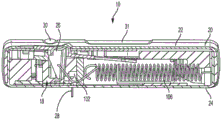
图2是根据本发明的一个方面的图1的药物输送系统的横截面透视图。2 is a cross-sectional perspective view of the drug delivery system of FIG. 1 according to one aspect of the present invention.
图3是根据本发明的一个方面的图1的药物输送系统的正视的横截面视图。Fig. 3 is a front cross-sectional view of the drug delivery system of Fig. 1 according to one aspect of the present invention.
图4是根据本发明的一个方面的图1的药物输送系统的俯视图,示出了壳体的顶部被移除并且药物输送系统处于使用前的位置中。4 is a top view of the drug delivery system of FIG. 1 showing the top of the housing removed and the drug delivery system in a pre-use position, according to one aspect of the present invention.
图5是根据本发明的一个方面的图1的药物输送系统的俯视的横截面视图,示出了药物输送系统处于使用前的位置中。5 is a top cross-sectional view of the drug delivery system of FIG. 1 , showing the drug delivery system in a pre-use position, according to one aspect of the present invention.
图6是根据本发明的一个方面的图1的药物输送系统的正视的横截面视图,示出了药物输送系统处于使用前的位置中。6 is a cross-sectional front elevational view of the drug delivery system of FIG. 1 showing the drug delivery system in a pre-use position according to an aspect of the present invention.
图7是根据本发明的一个方面的图1的药物输送系统的俯视图,示出了壳体的顶部被移除且药物输送系统处于初始致动位置中。7 is a top view of the drug delivery system of FIG. 1 showing the top of the housing removed and the drug delivery system in an initial actuated position, according to one aspect of the present invention.
图8是根据本发明的一个方面的图1的药物输送系统的正视的横截面视图,示出了药物输送系统处于初始致动位置中。8 is an elevational cross-sectional view of the drug delivery system of FIG. 1 , showing the drug delivery system in an initial actuated position, according to one aspect of the present invention.
图9是根据本发明的一个方面的图1的药物输送系统的正视的横截面视图,示出了药物输送系统处于初始致动位置中。9 is an elevational cross-sectional view of the drug delivery system of FIG. 1 showing the drug delivery system in an initial actuated position according to one aspect of the present invention.
图10是根据本发明的一个方面的图1的药物输送系统的俯视图,示出了壳体的顶部被移除且药物输送系统处于使用位置中。10 is a top view of the drug delivery system of FIG. 1 showing the top of the housing removed and the drug delivery system in the use position, according to one aspect of the present invention.
图11是根据本发明的一个方面的图1的药物输送系统的俯视的横截面视图,示出了药物输送系统处于使用位置中。11 is a top cross-sectional view of the drug delivery system of FIG. 1 , showing the drug delivery system in the use position, according to one aspect of the present invention.
图12是根据本发明的一个方面的图1的药物输送系统的正视的横截面视图,示出了药物输送系统处于使用位置中。12 is a cross-sectional elevational view of the drug delivery system of FIG. 1 showing the drug delivery system in the use position according to one aspect of the present invention.
图13是根据本发明的一个方面的图1的药物输送系统的俯视图,示出了壳体的顶部被移除且药物输送系统处于使用后的位置中。13 is a top view of the drug delivery system of FIG. 1 showing the top of the housing removed and the drug delivery system in a post-use position, according to one aspect of the present invention.
图14是根据本发明的一个方面的图1的药物输送系统的俯视的横截面视图,示出了药物输送系统处于使用后的位置中。14 is a top cross-sectional view of the drug delivery system of FIG. 1 , showing the drug delivery system in a post-use position, according to one aspect of the present invention.
图15是根据本发明的一个方面的图1的药物输送系统的正视的横截面视图,示出了药物输送系统处于使用后的位置中。15 is an elevational cross-sectional view of the drug delivery system of FIG. 1 showing the drug delivery system in a post-use position according to one aspect of the present invention.
图15A是根据本发明的一个方面的图1的药物输送系统的正视的横截面视图,示出了在药物输送系统处于使用前的位置中的情况下的衬垫。15A is an elevational cross-sectional view of the drug delivery system of FIG. 1 showing the liner with the drug delivery system in a pre-use position according to one aspect of the present invention.
图15B是根据本发明的一个方面的图1的药物输送系统的横截面透视图,示出了在药物输送系统处于使用前的位置中的情况下的衬垫。15B is a cross-sectional perspective view of the drug delivery system of FIG. 1 showing the liner with the drug delivery system in a pre-use position, according to one aspect of the present invention.
图15C是根据本发明的一个方面的图1的药物输送系统的横截面透视图,示出了在药物输送系统处于使用前的位置中的情况下的衬垫。15C is a cross-sectional perspective view of the drug delivery system of FIG. 1 showing the liner with the drug delivery system in a pre-use position, according to one aspect of the present invention.
图16是根据本发明的一个方面的图1的药物输送系统的局部横截面视图,示出了阀组件。16 is a partial cross-sectional view of the drug delivery system of FIG. 1 showing the valve assembly according to one aspect of the present invention.
图17是根据本发明的一个方面的药物输送系统的驱动组件的透视图。17 is a perspective view of a drive assembly of a drug delivery system according to an aspect of the present invention.
图18是根据本发明的一个方面的图17的驱动组件的横截面视图,示出了驱动组件的使用前的位置。18 is a cross-sectional view of the drive assembly of FIG. 17 showing the drive assembly in a pre-use position according to one aspect of the present invention.
图19是根据本发明的一个方面的图17的驱动组件的横截面视图,示出了驱动组件的使用位置。19 is a cross-sectional view of the drive assembly of FIG. 17 showing the drive assembly in use according to one aspect of the present invention.
图20是根据本发明的一个方面的图17的驱动组件的横截面视图,示出了驱动组件的使用后的位置。20 is a cross-sectional view of the drive assembly of FIG. 17 showing the drive assembly in a post-use position in accordance with an aspect of the present invention.
图21是根据本发明的一个方面的图17的驱动组件的柱塞致动构件的透视图。21 is a perspective view of a plunger actuation member of the drive assembly of FIG. 17 according to one aspect of the present invention.
图22是根据本发明的一个方面的图17的驱动组件的第一柱塞构件的透视图。22 is a perspective view of the first plunger member of the drive assembly of FIG. 17 according to one aspect of the present invention.
图23是根据本发明的一个方面的图17的驱动组件的柱塞致动构件和第一柱塞构件的透视图,示出了与第一柱塞构件接合的柱塞致动构件。23 is a perspective view of the plunger actuation member and the first plunger member of the drive assembly of FIG. 17 showing the plunger actuation member engaged with the first plunger member according to one aspect of the present invention.
图24是根据本发明的一个方面的图17的驱动组件的柱塞致动构件和第一柱塞构件的透视图,示出了与第一柱塞构件脱开的柱塞致动构件。24 is a perspective view of the plunger actuation member and the first plunger member of the drive assembly of FIG. 17 showing the plunger actuation member disengaged from the first plunger member in accordance with an aspect of the present invention.
图25是根据本发明的一个方面的图17的驱动组件的柱塞致动构件和第一柱塞构件的透视图,示出了与第一柱塞构件脱开并在轴向上相对于第一柱塞构件位移的柱塞致动构件。25 is a perspective view of the plunger actuation member and the first plunger member of the drive assembly of FIG. 17 according to an aspect of the present invention, shown disengaged from the first plunger member and axially relative to the first plunger member. A plunger actuating member for displacement of the plunger member.
图26是根据本发明的一个方面的图17的驱动组件的第一柱塞构件和第二柱塞构件的正视图。26 is a front view of the first plunger member and the second plunger member of the drive assembly of FIG. 17 according to one aspect of the present invention.
图27是根据本发明的另一方面的用于药物输送系统的驱动组件的俯视图。27 is a top view of a drive assembly for a drug delivery system according to another aspect of the present invention.
图28是根据本发明的一个方面的图27的驱动组件的透视图。28 is a perspective view of the drive assembly of FIG. 27 according to one aspect of the present invention.
图29是根据本发明的一个方面的图27的驱动组件的横截面视图,示出了驱动组件的使用前的位置。29 is a cross-sectional view of the drive assembly of FIG. 27 showing the drive assembly in a pre-use position in accordance with an aspect of the present invention.
图30是根据本发明的一个方面的图27的驱动组件的透视图,示出了由壳体的底部容纳的驱动组件。30 is a perspective view of the drive assembly of FIG. 27 showing the drive assembly received by the bottom of the housing in accordance with one aspect of the present invention.
图31是根据本发明的一个方面的图30的壳体的透视图。31 is a perspective view of the housing of FIG. 30 according to an aspect of the present invention.
图32是根据本发明的一个方面的图27的驱动组件的俯视图,示出了在驱动组件的初始致动位置中驱动组件与针致动器的一部分的接合。32 is a top view of the drive assembly of FIG. 27 showing engagement of the drive assembly with a portion of the needle actuator in an initial actuated position of the drive assembly in accordance with one aspect of the present invention.
图33是根据本发明的一个方面的图27的驱动组件的放大透视图,示出了在驱动组件的初始致动位置中驱动组件与针致动器的一部分的接合。33 is an enlarged perspective view of the drive assembly of FIG. 27 showing engagement of the drive assembly with a portion of the needle actuator in an initial actuated position of the drive assembly in accordance with one aspect of the present invention.
图34是根据本发明的一个方面的针致动器组件的正视图。34 is a front view of a needle actuator assembly according to one aspect of the present invention.
图35是根据本发明的一个方面的图34的针致动器组件的针梭的左侧透视图。35 is a left side perspective view of the needle shuttle of the needle actuator assembly of FIG. 34 in accordance with an aspect of the present invention.
图36是根据本发明的一个方面的图34的针致动器组件的针梭的右侧透视图。36 is a right side perspective view of the needle shuttle of the needle actuator assembly of FIG. 34 in accordance with an aspect of the present invention.
图37A是根据本发明的一个方面的图34的针致动器组件的正视图,示出了处于使用前的位置中的针致动器组件。37A is a front view of the needle actuator assembly of FIG. 34 showing the needle actuator assembly in a pre-use position according to one aspect of the present invention.
图37B是根据本发明的一个方面的图34的针致动器组件的正视图,示出了处于使用位置中的针致动器组件。37B is a front view of the needle actuator assembly of FIG. 34 showing the needle actuator assembly in the use position according to one aspect of the present invention.
图37C是根据本发明的一个方面的图34的针致动器组件的正视图,示出了处于初始使用后的位置中的针致动器组件。37C is a front view of the needle actuator assembly of FIG. 34 showing the needle actuator assembly in an initial post-use position according to one aspect of the present invention.
图37D是根据本发明的一个方面的图34的针致动器组件的正视图,示出了处于使用后的位置中的针致动器组件。37D is a front view of the needle actuator assembly of FIG. 34 showing the needle actuator assembly in the post-use position according to one aspect of the present invention.
图38A是根据本发明的一个方面的图34的针致动器组件的透视图,示出了处于使用位置中的针致动器组件。38A is a perspective view of the needle actuator assembly of FIG. 34 showing the needle actuator assembly in the use position according to one aspect of the present invention.
图38B是根据本发明的一个方面的图34的针致动器组件的透视图,示出了处于初始使用后的位置中的针致动器组件。38B is a perspective view of the needle actuator assembly of FIG. 34 showing the needle actuator assembly in an initial post-use position according to one aspect of the present invention.
图39是根据本发明的一个方面的图34的致动器按钮和针致动器组件的透视图,示出了处于初始使用后的位置中的针致动器组件。39 is a perspective view of the actuator button and needle actuator assembly of FIG. 34 showing the needle actuator assembly in an initial post-use position according to one aspect of the present invention.
图40A是根据本发明的一个方面的图34的致动器按钮和针致动器组件的横截面视图,示出了处于初始使用后的位置中的针致动器组件。40A is a cross-sectional view of the actuator button and needle actuator assembly of FIG. 34 showing the needle actuator assembly in an initial post-use position, according to one aspect of the present invention.
图40B是根据本发明的一个方面的图34的致动器按钮和针致动器组件的透视图,示出了处于使用后的位置中的针致动器组件。40B is a perspective view of the actuator button and needle actuator assembly of FIG. 34 showing the needle actuator assembly in a post-use position according to one aspect of the present invention.
图41是根据本发明的另一方面的用于药物输送系统的驱动组件的透视图。41 is a perspective view of a drive assembly for a drug delivery system according to another aspect of the present invention.
图42是根据本发明的一个方面的图41的驱动组件的透视图,示出了壳体的顶部被移除。42 is a perspective view of the drive assembly of FIG. 41 showing the top of the housing removed, according to an aspect of the present invention.
图43是根据本发明的一个方面的图41的驱动组件的横截面视图。43 is a cross-sectional view of the drive assembly of FIG. 41 according to one aspect of the present invention.
图44是根据本发明的一个方面的图41的驱动组件的透视图。44 is a perspective view of the drive assembly of FIG. 41 according to one aspect of the present invention.
图45是根据本发明的一个方面的图41的驱动组件的横截面视图,示出了处于使用前的位置中的驱动组件。45 is a cross-sectional view of the drive assembly of FIG. 41, showing the drive assembly in a pre-use position, according to an aspect of the present invention.
图46是根据本发明的一个方面的图41的驱动组件的横截面视图,示出了处于使用前的位置中的驱动组件。46 is a cross-sectional view of the drive assembly of FIG. 41, showing the drive assembly in a pre-use position, according to an aspect of the present invention.
图47是根据本发明的一个方面的图41的驱动组件的俯视图,示出了处于使用前的位置中的驱动组件。47 is a top view of the drive assembly of FIG. 41, showing the drive assembly in a pre-use position, according to an aspect of the present invention.
图48是根据本发明的一个方面的图41的驱动组件的俯视图,示出了处于初始致动位置中的驱动组件。48 is a top view of the drive assembly of FIG. 41, showing the drive assembly in an initial actuated position, according to one aspect of the present invention.
图49是根据本发明的一个方面的图41的驱动组件的俯视图,示出了处于初始致动位置中的驱动组件。49 is a top view of the drive assembly of FIG. 41, showing the drive assembly in an initial actuated position, according to one aspect of the present invention.
图50是根据本发明的一个方面的图41的驱动组件的俯视图,示出了处于初始致动位置中的驱动组件。50 is a top view of the drive assembly of FIG. 41, showing the drive assembly in an initial actuated position, according to one aspect of the present invention.
图51是根据本发明的一个方面的图41的驱动组件的俯视图,示出了处于使用位置中的驱动组件。51 is a top view of the drive assembly of FIG. 41, showing the drive assembly in the use position, according to one aspect of the present invention.
图52是根据本发明的一个方面的图41的驱动组件的俯视图,示出了处于使用位置中的驱动组件。52 is a top view of the drive assembly of FIG. 41, showing the drive assembly in the use position, according to one aspect of the present invention.
图53是根据本发明的一个方面的图41的驱动组件的横截面视图,示出了处于使用位置中的驱动组件。53 is a cross-sectional view of the drive assembly of FIG. 41, showing the drive assembly in the use position, according to an aspect of the present invention.
图54是根据本发明的一个方面的图41的驱动组件的俯视图,示出了处于使用位置中的驱动组件。54 is a top view of the drive assembly of FIG. 41, showing the drive assembly in the use position, according to one aspect of the present invention.
图55是根据本发明的一个方面的图41的驱动组件的横截面视图,示出了处于使用位置中的驱动组件。55 is a cross-sectional view of the drive assembly of FIG. 41, showing the drive assembly in the use position, according to an aspect of the present invention.
图56是根据本发明的一个方面的图41的驱动组件的横截面视图,示出了处于使用位置中的驱动组件。56 is a cross-sectional view of the drive assembly of FIG. 41, showing the drive assembly in the use position, according to an aspect of the present invention.
图57是根据本发明的一个方面的图41的驱动组件的俯视图,示出了处于使用位置中的驱动组件。57 is a top view of the drive assembly of FIG. 41, showing the drive assembly in the use position, according to one aspect of the present invention.
图58是根据本发明的一个方面的图41的驱动组件的俯视图,示出了处于初始使用后的位置中的驱动组件。58 is a top view of the drive assembly of FIG. 41, showing the drive assembly in an initial post-use position, according to an aspect of the present invention.
图59是根据本发明的一个方面的图41的驱动组件的透视图,示出了处于初始使用后的位置中的驱动组件。59 is a perspective view of the drive assembly of FIG. 41, showing the drive assembly in an initial post-use position, according to an aspect of the present invention.
图60是根据本发明的一个方面的图41的驱动组件的俯视图,示出了处于使用后的位置中的驱动组件。60 is a top view of the drive assembly of FIG. 41, showing the drive assembly in a post-use position, according to an aspect of the present invention.
图61是根据本发明的一个方面的图41的驱动组件的俯视图,示出了处于使用后的位置中的驱动组件。61 is a top view of the drive assembly of FIG. 41, showing the drive assembly in a post-use position, according to an aspect of the present invention.
图62是根据本发明的一个方面的图41的驱动组件的横截面视图,示出了处于使用前的位置中的驱动组件。62 is a cross-sectional view of the drive assembly of FIG. 41, showing the drive assembly in a pre-use position, according to an aspect of the present invention.
图63是根据本发明的一个方面的图41的驱动组件的横截面视图,示出了处于使用位置中的驱动组件。63 is a cross-sectional view of the drive assembly of FIG. 41, showing the drive assembly in the use position, according to an aspect of the present invention.
图64是根据本发明的另一方面的驱动组件的透视图。64 is a perspective view of a drive assembly according to another aspect of the invention.
图65A是根据本发明的一个方面的针致动器组件的正视图,示出了处于使用位置中的针致动器组件。65A is a front view of a needle actuator assembly according to an aspect of the present invention, showing the needle actuator assembly in the use position.
图65B是根据本发明的一个方面的图65A的针致动器组件的正视图,示出了处于使用位置中的针致动器组件。65B is a front view of the needle actuator assembly of FIG. 65A showing the needle actuator assembly in the use position according to one aspect of the present invention.
图65C是根据本发明的一个方面的图65A的针致动器组件的正视图,示出了处于初始使用后的位置中的针致动器组件。65C is a front view of the needle actuator assembly of FIG. 65A showing the needle actuator assembly in an initial post-use position according to one aspect of the present invention.
图65D是根据本发明的一个方面的图65A的针致动器组件的正视图,示出了处于使用后的位置中的针致动器组件。65D is a front view of the needle actuator assembly of FIG. 65A showing the needle actuator assembly in the post-use position according to one aspect of the present invention.
图65E是根据本发明的一个方面的图65A的针致动器组件的正视图,示出了处于使用前的位置中的针致动器组件。65E is a front view of the needle actuator assembly of FIG. 65A showing the needle actuator assembly in a pre-use position according to one aspect of the present invention.
图65F是根据本发明的一个方面的图65A的针致动器组件的横截面视图,示出了处于使用前的位置中的针致动器组件。65F is a cross-sectional view of the needle actuator assembly of FIG. 65A, showing the needle actuator assembly in a pre-use position, according to one aspect of the present invention.
图65G是根据本发明的一个方面的图65A的针致动器组件的正视图,示出了在按钮致动器轴向位移的情况下处于使用前的位置中的针致动器组件。65G is a front view of the needle actuator assembly of FIG. 65A showing the needle actuator assembly in the pre-use position with the button actuator axially displaced, according to one aspect of the present invention.
图65H是根据本发明的一个方面的图65A的针致动器组件的横截面视图,示出了在按钮致动器轴向位移的情况下处于使用前的位置中的针致动器组件。65H is a cross-sectional view of the needle actuator assembly of FIG. 65A showing the needle actuator assembly in a pre-use position with axial displacement of the button actuator, according to one aspect of the present invention.
图66是根据本发明的一个方面的图65A的针致动器组件的按钮弹簧的透视图。66 is a perspective view of the button spring of the needle actuator assembly of FIG. 65A according to one aspect of the present invention.
图67是根据本发明的一个方面的图65A的针致动器组件的致动器按钮的透视图。67 is a perspective view of the actuator button of the needle actuator assembly of FIG. 65A according to one aspect of the present invention.
图68是根据本发明的一个方面的图65A的针致动器组件的按钮弹簧和致动器按钮的横截面视图。68 is a cross-sectional view of the button spring and actuator button of the needle actuator assembly of FIG. 65A in accordance with one aspect of the present invention.
图68A是根据本发明的另一方面的图65A的针致动器组件的致动器按钮的透视图。68A is a perspective view of the actuator button of the needle actuator assembly of FIG. 65A according to another aspect of the present invention.
图68B是根据本发明的另一方面的图65A的针致动器组件的致动器按钮的仰视图。68B is a bottom view of the actuator button of the needle actuator assembly of FIG. 65A according to another aspect of the present invention.
图68C是根据本发明的另一方面的图65A的针致动器组件的致动器按钮的正视图。68C is a front view of the actuator button of the needle actuator assembly of FIG. 65A according to another aspect of the present invention.
图68D是根据本发明的另一方面的图65A的针致动器组件的致动器按钮的俯视图,示出了处于使用前的位置中的致动器按钮。68D is a top view of the actuator button of the needle actuator assembly of FIG. 65A showing the actuator button in a pre-use position according to another aspect of the present invention.
图68E是根据本发明的另一方面的图65A的针致动器组件的致动器按钮的正视图,示出了处于使用前的位置中的致动器按钮。68E is a front view of the actuator button of the needle actuator assembly of FIG. 65A showing the actuator button in a pre-use position according to another aspect of the present invention.
图68F是根据本发明的另一方面的图65A的针致动器组件的致动器按钮的俯视图,示出了处于使用位置中的致动器按钮。68F is a top view of the actuator button of the needle actuator assembly of FIG. 65A showing the actuator button in the use position according to another aspect of the present invention.
图68G是根据本发明的另一方面的图65A的针致动器组件的致动器按钮的正视图,示出了处于使用位置中的致动器按钮。68G is a front view of the actuator button of the needle actuator assembly of FIG. 65A showing the actuator button in the use position according to another aspect of the present invention.
图69是根据本发明的一个方面的图65A的针致动器组件的致动器按钮的俯视图。69 is a top view of the actuator button of the needle actuator assembly of FIG. 65A according to one aspect of the present invention.
图70A是根据本发明的一个方面的驱动组件的示意图,示出了处于使用前的位置中的驱动组件。70A is a schematic illustration of a drive assembly according to an aspect of the present invention, showing the drive assembly in a pre-use position.
图70B是根据本发明的一个方面的图70A的驱动组件的示意图,示出了处于使用位置中的驱动组件。70B is a schematic illustration of the drive assembly of FIG. 70A, showing the drive assembly in the use position, according to one aspect of the present invention.
图70C是根据本发明的一个方面的图70A的驱动组件的示意图,示出了处于使用位置中的驱动组件。70C is a schematic illustration of the drive assembly of FIG. 70A, showing the drive assembly in the use position, according to one aspect of the present invention.
图70D是根据本发明的一个方面的图70A的驱动组件的示意图,示出了处于使用位置中的驱动组件。70D is a schematic illustration of the drive assembly of FIG. 70A, showing the drive assembly in an in-use position, according to an aspect of the present invention.
图70E是根据本发明的一个方面的图70A的驱动组件的示意图,示出了处于使用位置中的驱动组件。70E is a schematic illustration of the drive assembly of FIG. 70A, showing the drive assembly in the use position, according to one aspect of the present invention.
图70F是根据本发明的一个方面的图70A的驱动组件的示意图,示出了处于使用后的位置中的驱动组件。70F is a schematic illustration of the drive assembly of FIG. 70A, showing the drive assembly in a post-use position, according to an aspect of the present invention.
图70G是根据本发明的一个方面的图70A的驱动组件的示意图,示出了处于使用后的位置中的驱动组件。70G is a schematic illustration of the drive assembly of FIG. 70A, showing the drive assembly in a post-use position, according to one aspect of the present invention.
图71是根据本发明的一个方面的用于药物输送系统的间隔件组件的透视图,示出了组装好的在使用前的位置中的间隔件组件。71 is a perspective view of a septum assembly for a drug delivery system according to an aspect of the present invention, showing the septum assembly assembled in a pre-use position.
图72是根据本发明的一个方面的图71的间隔件组件的透视图,示出了间隔件组件的使用位置。72 is a perspective view of the spacer assembly of FIG. 71 showing the spacer assembly in a position of use, according to one aspect of the present invention.
图73是根据本发明的一个方面的图71的间隔件组件的透视图,示出了间隔件组件的初始使用后的位置。73 is a perspective view of the spacer assembly of FIG. 71 showing the spacer assembly in an initial post-use position, according to an aspect of the present invention.
图74是根据本发明的一个方面的限制构件的透视图。74 is a perspective view of a restraint member according to an aspect of the present invention.
图75是根据本发明的另一方面的药物输送系统的间隔件组件的正视图。75 is a front view of a septum assembly of a drug delivery system according to another aspect of the present invention.
图76是根据本发明的一个方面的药物输送系统的间隔件组件的俯视图。76 is a top view of a septum assembly of a drug delivery system according to one aspect of the present invention.
图77是根据本发明的一个方面的图76的间隔件组件的透视图。77 is a perspective view of the spacer assembly of FIG. 76 according to one aspect of the present invention.
图78是根据本发明的一个方面的图76的间隔件组件的横截面视图。78 is a cross-sectional view of the spacer assembly of FIG. 76 according to one aspect of the present invention.
图79是根据本发明的另一方面的用于药物输送系统的间隔件组件的透视图。79 is a perspective view of a septum assembly for a drug delivery system according to another aspect of the present invention.
图80是根据本发明的另一方面的用于药物输送系统的间隔件组件的透视图。80 is a perspective view of a septum assembly for a drug delivery system according to another aspect of the present invention.
图81A是根据本发明的一个方面的图80的间隔件组件的横截面视图,示出了间隔件组件的组装前的位置。81A is a cross-sectional view of the spacer assembly of FIG. 80 showing the pre-assembly position of the spacer assembly according to one aspect of the present invention.
图81B是根据本发明的一个方面的图80的间隔件组件的横截面视图,示出了间隔件组件的组装好的位置。81B is a cross-sectional view of the spacer assembly of FIG. 80 showing the spacer assembly in an assembled position according to one aspect of the present invention.
图82是根据本发明的一个方面的用于药物输送系统的驱动组件的透视图。82 is a perspective view of a drive assembly for a drug delivery system according to one aspect of the present invention.
图83是根据本发明的一个方面的图82的驱动组件的透视图,示出了壳体的顶部被移除。83 is a perspective view of the drive assembly of FIG. 82 showing the top of the housing removed, according to an aspect of the present invention.
图84是根据本发明的一个方面的图82的驱动组件的横截面视图,示出了驱动组件的使用前的位置。84 is a cross-sectional view of the drive assembly of FIG. 82 showing the drive assembly in a pre-use position in accordance with an aspect of the present invention.
图85是根据本发明的一个方面的图82的驱动组件的放大横截面视图,示出了驱动组件的使用前的位置。85 is an enlarged cross-sectional view of the drive assembly of FIG. 82 showing the drive assembly in a pre-use position in accordance with an aspect of the present invention.
图86是根据本发明的一个方面的图82的驱动组件的偏压构件的俯视图。86 is a top view of a biasing member of the drive assembly of FIG. 82 according to one aspect of the present invention.
图87是根据本发明的一个方面的图82的驱动组件的透视图,示出了与驱动组件接合的限制构件。87 is a perspective view of the drive assembly of FIG. 82 showing a restraint member engaged with the drive assembly in accordance with one aspect of the present invention.
图88是根据本发明的一个方面的用于药物输送系统的驱动组件的透视图。88 is a perspective view of a drive assembly for a drug delivery system according to one aspect of the present invention.
图89是根据本发明的一个方面的图88的驱动组件的透视图,示出了驱动组件的使用前的位置。89 is a perspective view of the drive assembly of FIG. 88 showing the drive assembly in a pre-use position in accordance with an aspect of the present invention.
图90是根据本发明的一个方面的图88的驱动组件的横截面视图。90 is a cross-sectional view of the drive assembly of FIG. 88 according to one aspect of the present invention.
图91是根据本发明的一个方面的图88的驱动组件的透视图,示出了驱动组件的使用后的位置。91 is a perspective view of the drive assembly of FIG. 88 showing the drive assembly in a post-use position in accordance with an aspect of the present invention.
图92是根据本发明的一个方面的图88的驱动组件的横截面视图,示出了驱动组件的使用前的位置。92 is a cross-sectional view of the drive assembly of FIG. 88 showing the drive assembly in a pre-use position in accordance with an aspect of the present invention.
图93是根据本发明的一个方面的图88的驱动组件的正视图,示出了驱动组件的使用位置。93 is an elevational view of the drive assembly of FIG. 88 showing the drive assembly in use according to an aspect of the present invention.
图94是根据本发明的一个方面的用于药物输送系统的间隔件组件的透视图。94 is a perspective view of a septum assembly for a drug delivery system according to one aspect of the present invention.
图95是根据本发明的一个方面的图94的间隔件组件的正视图。95 is an elevational view of the spacer assembly of FIG. 94 according to one aspect of the present invention.
图96是根据本发明的一个方面的图94的间隔件组件的横截面视图。96 is a cross-sectional view of the spacer assembly of FIG. 94 according to one aspect of the present invention.
图97是根据本发明的一个方面的图94的间隔件组件的透视图,示出了垫片被移除。97 is a perspective view of the spacer assembly of FIG. 94 showing the spacer removed, according to an aspect of the present invention.
图98是根据本发明的一个方面的图94的间隔件组件的固定间隔件的透视图。98 is a perspective view of a stationary spacer of the spacer assembly of FIG. 94 in accordance with one aspect of the present invention.
图99是根据本发明的一个方面的图94的间隔件组件的可调节间隔件的透视图。99 is a perspective view of an adjustable spacer of the spacer assembly of FIG. 94 in accordance with one aspect of the present invention.
图100是根据本发明的一个方面的图94的间隔件组件的垫片的透视图。100 is a perspective view of a spacer of the spacer assembly of FIG. 94 according to an aspect of the present invention.
多个视图中相应的附图标记表示相应的部件。这里陈述的范例阐述了本发明的示例性方面,这些范例并不解释为以任何方式对本公开的范围构成限制。Corresponding reference characters indicate corresponding parts throughout the several views. The exemplifications set forth herein illustrate exemplary aspects of the invention and are not to be construed as limiting the scope of the disclosure in any way.
具体实施方式Detailed ways
提供下面的描述是为了使本领域技术人员能够制造和使用为了实施本发明而设想的所述实施方式。然而,各种修改、等价方式、变型和替换对于本领域技术人员来说是显而易见的。任何的以及所有的这些修改、变型、等价方式和替换旨在落入本发明的精髓和范围内。The following description is provided to enable those skilled in the art to make and use the described embodiments contemplated for carrying out the invention. However, various modifications, equivalents, variations, and substitutions will be apparent to those skilled in the art. Any and all such modifications, variations, equivalents and substitutions are intended to fall within the spirit and scope of the invention.
为了下文描述的目的,术语“上”、“下”、“右”、“左”、“竖直”、“水平”、“顶”、“底”、“横向”、“纵向”以及它们的派生词均与本发明在附图中的取向有关。然而,应该理解的是本发明可以采用各种替代性的变型,除非明确相反地说明。还应该理解的是附图中示出的并且在下面的说明中描述的特定装置仅是本发明的示例性实施方式。因此,与这里披露的实施方式相关的特定尺寸和其他物理特性并不认为构成限制。For the purposes of the following description, the terms "upper", "lower", "right", "left", "vertical", "horizontal", "top", "bottom", "transverse", "longitudinal" and their Derivatives are all relative to the orientation of the invention in the drawings. However, it should be understood that the invention may employ various alternative modifications unless expressly stated to the contrary. It should also be understood that the particular arrangements shown in the drawings and described in the following description are merely exemplary embodiments of the invention. Accordingly, specific dimensions and other physical characteristics related to the embodiments disclosed herein are not to be considered limiting.
参见图1-16,根据本发明的一个方面的药物输送系统10包括驱动组件12、容器14、阀组件16和针致动器组件18。驱动组件12、容器14、阀组件16和针致动器组件18至少部分地位于壳体20内。壳体20包括顶部22和底部24,不过壳体20可以使用其他合适的布置。在一个方面中,药物输送系统10是一种注射器装置,其配置成被用户穿戴或者被紧固到用户并经由注射向用户体内输送设置在容器14内的预定剂量的药剂。系统10可以用于进行“大剂量注射”(bolus injection),在所述大剂量注射中,在设定时间段内输送药剂。可以在长达45分钟的时间段内输送药剂,不过可以使用其他合适的注射量和持续时间。可以利用速度控制或者没有特定的速度控制的情况下实施大剂量施药或输送。在速度可变的情况下,系统10可以以固定压力向用户输送药剂。下面参照图1-16以及后面结合图17-93讨论的系统10的驱动组件12、针致动器组件18和其他特征的细节来描述系统10的一般操作。Referring to FIGS. 1-16 , a
再次参见图1-16,系统10配置成通过用户对致动按钮26的接合(这导致针组件18的针28刺穿用户的皮肤)、驱动组件12的致动(以使针28与容器14流体联通并将流体或药剂从容器14排出)、以及在药剂注射完成之后针28的退回来进行操作。在国际公报号2013/155135和2014/179774中示出并描述了一种药物输送系统的一般操作,通过引用将其全文并入于此。系统10的壳体20包括用于观察指示器装置32的指示器窗口30以及用于观察容器14的容器窗口31,指示器装置32配置成向用户提供关于系统10的状态的指示。指示器窗口30可以是用于提供指示器装置32的清楚视图的放大镜。在系统10使用过程中,指示器装置32与针致动器组件18一起移动以指示系统10的使用前的状态、使用状态和使用后的状态。指示器装置32提供了与状态有关的视觉标记,不过可以提供其他合适的标记(比如听觉上的或触觉上的)作为替代性的或者附加的标记。Referring again to FIGS. 1-16 , the
参见图4-6,在系统10的使用前的位置中,容器14与驱动组件12和阀组件16间隔开,针28处于缩回的位置中。如图7-9所示,在系统10的初始致动过程中,驱动组件12接合容器14以使容器14朝向阀组件16移动,阀组件16配置成刺穿容器14的封闭件36并经由管(未示出)或其他合适的装置使容器14内的药剂与针28流体联通。驱动组件12配置成接合容器14的塞34,这样由于容器14内的流体或药剂的不可压缩性而最开始使整个容器14移动成与阀组件16接合。系统10的初始致动是由用户接合致动按钮26而实现的,这样释放了针致动器组件18和驱动组件12,正如下面更详细讨论的。在初始致动过程中,针28仍然处于缩回的位置中,并且即将移动到伸出位置来对系统10的用户进行注射。4-6, in the pre-use position of
如图10-12所示,在系统10的使用位置中,针28处于伸出位置中,至少部分地在壳体20的外部,其中驱动组件12使容器14内的塞34移动以将药剂从容器14通过针28输送到用户。在使用位置中,阀组件16已经刺穿了容器14的封闭件36,以使容器14与针28流体联通,这样还允许驱动组件12使塞34相对于容器14移动,因为流体流体能够从容器14分配。如图13-15所示,在系统10的使用后的位置中,针28处于缩回的位置中并且与衬垫38接合,以将针28密封并防止任何残留的流体或药剂从容器14流出。容器14和阀组件16可以是在国际公报号WO2015/081337中示出并描述的容器14和阀组件16,其通过引用全文并入于此。As shown in FIGS. 10-12 , in the use position of the
参见图15A-15C,当针致动器本体96从使用位置移动到使用后的位置时,衬垫38被偏压到衬垫中。特别地,衬垫38由具有凸轮表面124的衬垫臂122容纳,凸轮表面124与壳体20底部24上的凸轮轨道126配合作用。衬垫臂122经由扭力杆128连接到针致动器本体96。凸轮表面124配置成接合凸轮轨道126,以使衬垫臂122向下偏转,从而允许衬垫38在被向上偏压到针28中之前从针28下面通过。扭力杆128允许衬垫臂122围绕针致动器本体96的枢轴扭转。衬垫38可以压配合到衬垫臂122的开口中,不过可以使用其他合适的用于紧固衬垫38的装置。15A-15C, when the
参见图1-33,示出了根据本发明的一个方面的驱动组件12。正如上面讨论的,驱动组件12配置成使容器14移动,以刺穿容器14的封闭件36并使塞34在容器14内移动以从容器14分配流体或药剂。图17-33中示出的驱动组件12配置成与由容器14的塞34容纳的间隔件组件40接合并与该间隔件组件40配合作用。间隔件组件40包括间隔件42和间隔件保持器44。间隔件保持器44由塞34容纳,间隔件42由间隔件保持器44容纳。间隔件保持器44包括第一螺纹部46,其与塞34的相应的螺纹部接合,不过可以使用其他合适的装置。间隔件42也包括螺纹部48,其与间隔件保持器44的相应的第二螺纹部50接合,以用于将间隔件42紧固到间隔件保持器44,不过可以使用其他合适的装置。驱动组件12配置成分配容器14的一定范围的预定填充容积并同时保持上述的系统10的功能特征,包括但不限于在剂量分配结束之后缩回针28并且提供对系统10的状态的指示,同时还将塞34与驱动组件12的突然接合的可能性降到最低。驱动组件12配置成通过使用多个尺寸的间隔件42分配多个不连续的填充容积范围。在一个方面中,提供12个填充容积范围和12个间隔件42。在一个方面中,改变间隔件42的长度以适应容器14中不同的填充容积。替代性地,可以使用单个尺寸的间隔件42,其中,通过使用由间隔件42容纳的多个垫片来适配容器14中的多个填充容积。Referring to Figures 1-33, a
参见图17-26,驱动组件12包括第一柱塞构件52、由第一柱塞构件52容纳的第二柱塞构件54、第一偏压构件56、第二偏压构件58、柱塞致动构件60、以及转位构件62。第一柱塞构件52可以从使用前的位置(如图18中所示)移动到使用位置(如图19中所示)、移动到使用后的位置(如图20中所示),其中第一柱塞构件52配置成与间隔件组件40接合并使塞34在容器14内移动以从容器14分配药剂。第一柱塞构件52配置成轴向移动。第二柱塞构件54和第一柱塞构件52形成伸缩装置,其中第二柱塞54配置成在第一柱塞构件52移动预定的轴向距离之后轴向移动。第一和第二柱塞构件52、54的移动是由第一和第二偏压构件56、58提供的,第一和第二偏压构件是压缩弹簧,不过可以使用其他合适的装置用作偏压构件56、58。17-26, the
第一偏压构件56由第二柱塞构件54容纳并被约束在柱塞致动构件60(和转位构件62)与第二柱塞构件54的第一弹簧座64之间。第二偏压构件58自第一偏压构件56径向向内定位并且由第二柱塞构件54容纳。第二偏压构件58被约束在第二柱塞构件54的第二弹簧座66与第一柱塞构件52之间。第二偏压构件58配置成将第一柱塞构件52朝向容器14从使用前的位置偏压到使用位置、并偏压到使用后的位置。第一偏压构件56配置成将第二柱塞构件54朝向容器14偏压,这进而将第一柱塞构件52朝向容器14从使用前的位置偏压到使用位置、并偏压到使用后的位置。更具体地,第二偏压构件58配置成将第一柱塞构件52驱动到间隔件组件40或塞34上,以使容器14移动成与阀组件16接合,从而刺穿容器14的封闭件36并使容器14与针28流体联通。第一偏压构件56配置成使塞34在容器14内移动,以分配容器14内的药剂。第二偏压构件58相比于第一偏压构件56具有不同的弹簧常数。特别地,第二偏压构件58比第一偏压构件56刚度更大,以提供大的力来刺穿容器14的封闭件36,而第一偏压构件56提供较小的力,用于根据容器14内的流体或药剂的粘性来进行适当分配。The
再次参见图17-26,柱塞致动构件60具有环形部68和轴部70。柱塞致动构件60可以相对于第一柱塞构件52在第一转动位置和与第一转动位置间隔开的第二转动位置之间旋转地运动。第一转动位置可以与第二转动位置间隔15度,不过可以使用其他合适的位置。环形部68包括驱动表面72,驱动表面72包括多个轮齿74,不过可以使用用于驱动表面72的其他合适的装置。轴部70包括致动器锁定表面76,该致动器锁定表面配置成与第一柱塞构件52的柱塞锁定表面78接合和释放。柱塞锁定表面78包括多个凸出部80,这些凸出部配置成容纳在由致动器锁定表面76限定的多个狭槽或切口81中。Referring again to FIGS. 17-26 , the
如图18和23中所示,在柱塞致动构件60的第一转动位置中,所述多个凸出部80和多个狭槽或切口81没有对准,使得柱塞致动构件80与第一柱塞构件52接合以防止第一和第二柱塞构件52、54与将第一和第二柱塞构件52、54偏压远离柱塞致动构件60的第一和第二偏压构件56、58一起移动。如图19和24中所示,在柱塞致动构件60的第二转动位置中,所述多个凸出部80和多个狭槽或切口81彼此对准,使得柱塞致动构件60与第一柱塞构件52脱开,以使第一和第二柱塞构件52、54能够移动,从而开始从容器14的分配过程。18 and 23, in the first rotational position of the
参见图7和33,柱塞致动构件60的驱动表面72配置成与针致动器组件18的一部分接合。在接合致动器按钮26并释放针致动器组件18(在下面要更详细地讨论)之后,针致动器组件18在壳体20内从使用前的位置移动到使用位置和使用后的位置。在针致动器组件18的初始移动过程中,针致动器组件18的一部分与柱塞致动构件60的驱动表面72接合,以使柱塞致动构件60从第一转动位置移动到第二转动位置。如图33中所示,针致动器组件18的倾斜叶片部82与柱塞致动构件60的驱动表面72接合以使柱塞致动构件60转动。Referring to FIGS. 7 and 33 , the
参见图11、13和26,第二柱塞构件52包括多个编码凸出部84,其中所述多个编码凸出部84中预先选出的一个配置成与系统10的限制构件86接合。正如下面更详细讨论的,限制构件86与针致动器组件18配合、并限制针致动器组件18从使用位置移动到使用后的位置,直到塞34到达预定的用药结束位置。在一个方面中,限制构件86配置成通过限制构件86与针致动器组件18的一部分的接合而限制针致动器组件18从使用位置的轴向移动。当塞34到达用药结束位置时,通过限制构件86的转动释放限制构件86与针致动器组件18之间的这种接合。在针致动器组件18的使用位置中,限制构件86被在转动方向上偏压,其中通过限制构件86与第二柱塞构件54的所述多个编码凸出部84中的一个之间的接合来阻止限制构件86的转动。所述多个编码凸出部84可以是具有变化长度的轴向肋,不过可以使用其他合适的装置。每个编码凸出部84限定一个点,在该点上,限制构件86能够转动,从而释放针致动器组件18。第二柱塞构件52的平滑部还可以提供另外的“编码”,用于确定系统10何时转变到用药结束位置。Referring to FIGS. 11 , 13 and 26 , the
正如上面讨论的,指示器装置32移动,其中当系统10从使用前的位置、使用位置或用药结束位置移动时,指示器装置32的不同部分通过指示器窗口30是可见的。更具体地,指示器装置32接合限制构件86的一部分并且与限制构件86一起移动通过系统10的各个阶段,以向用户提供与系统10的状态有关的指示。As discussed above,
在系统10的组装过程中,容器14的剂量与具有设定长度的特定间隔件42匹配,所述多个编码凸出部84的相应的一个编码凸出部与限制构件86对准。因此,正如上面讨论的,容器14可以设有多个剂量体积,其中每个剂量体积对应于特定的间隔件42和编码凸出部84。因此,甚至对于不同的剂量体积,系统10配置成使针28注入到用户体内,以从容器14输送一定剂量的药剂,在用药结束之后使针28缩回,并提供系统10的状态指示,同时将塞34与驱动组件12的突然接合的可能性降到最低。特别地,塞34的尺寸可以选择成将第一柱塞构件52与间隔件组件40之间的距离减到最小并且不需要使用阻尼。During assembly of the
参见图27-33,示出了根据本发明的另一方面的驱动组件12A。图27-33中示出的驱动组件12A与图17-26中示出并在上面描述的驱动组件12类似并且以相同的方式操作。然而,在图27-33的驱动组件中,第一柱塞构件52由第二柱塞构件54容纳并且在从使用前的位置到使用位置的轴向移动过程中自第二柱塞构件54延伸。此外,第一柱塞构件52包括延伸部88,该延伸部配置成在第一柱塞构件52移动预定的轴向距离之后与第二柱塞构件54接合,使得第一和第二柱塞构件52、54一起移动。第一和第二偏压构件56、58以与图17-26的驱动组件12相同的方式接合和作用在第一和第二柱塞构件52、54上。27-33, there is shown a
参见图27-32,转位构件62位于第一和第二柱塞构件52、54周围并且包括多个棘齿90,这些棘齿配置成与位于壳体20的底部24上的柔性凸片92接合。当驱动组件12、12A安装到壳体20的底部24中时,转位构件62的棘齿90与壳体20的柔性凸片92接合会提供转位构件62的单向转动。转位构件62配置成转动,以基于如上讨论的剂量体积和间隔件42尺寸使第二柱塞构件52的其中一个编码凸出部84与限制构件86对准。转位构件62可以为驱动组件12、12A提供24个转动位置,其中的12个转动位置具有与它们有关的唯一剂量值。Referring to FIGS. 27-32 , the
参见图1-16和34-40B,示出了根据本发明的一个方面的针致动器组件18。针致动器组件18包括具有导向表面98的针致动器本体96、具有凸轮表面104的针梭102、和由针梭102容纳并配置成正如上面讨论的与容器14流体联通的针28。针致动器本体96总体是矩形的,其中导向表面98径向向内突出。针梭102容纳在针致动器本体96内。如上所述,针致动器本体96可以在壳体20内从使用前的位置(如图4-6中所示)、初始致动位置(图7-9)、使用位置(图10-12)、和使用后的位置(图13-15)移动。针致动器本体96经由拉伸弹簧106被从使用前的位置偏压到使用后的位置,不过可以使用其他合适的偏压装置。一旦接合致动器按钮26(在下面会更详细地讨论),针致动器本体96被释放并自由地从使用前的位置移动到使用位置。正如上面结合图17-33讨论的,在限制构件86转动之后,针致动器本体96从使用位置移动到使用后的位置。Referring to Figures 1-16 and 34-40B, there is shown a
参见图34-40B,针梭102可以沿着竖直轴线在缩回位置与伸出位置之间移动,在缩回位置中针28位于壳体20内,在伸出位置中针28的至少一部分从壳体20伸出。针梭102配置成通过针致动器96的导向表面98与针梭102的凸轮表面104之间的接合而在缩回位置与伸出位置之间移动。凸轮表面104由第一和第二凸轮构件108、110提供,其中第一凸轮构件108与第二凸轮构件110间隔开。壳体20包括导向柱112,该导向柱112具有配置成容纳针梭102上的T形凸出部114的凹槽,不过导向柱112和T形凸出部114可以使用其他形状和结构。针梭102沿着导向柱112在缩回位置与伸出位置之间移动。导向柱112是直线的并且自壳体20大致垂直延伸,不过可以使用其他合适的装置。针致动器本体86的导向表面98是非直线的并且每个均包括第一侧面116和与第一侧面116相对定位的第二侧面118。34-40B, the
如下面讨论的,针致动器本体96的导向表面98与针梭102的凸轮构件108、110配合,以在针致动器本体96从使用前的位置轴向移动到使用后的位置时使针梭102在缩回位置与伸出位置之间竖直移动。针梭102还包括配置成与壳体20或致动器按钮26接合的梭偏压构件120。特别地,梭偏压构件120接合壳体20或致动器按钮26并在针致动器本体96从使用位置转换到使用后的位置时提供偏压力。当针致动器本体96完全转换到使用后的位置时,针梭102的凸轮构件108、110与针致动器本体96的导向表面98脱开,并且梭偏压构件120将针梭102向下偏压使得针28如上面讨论的那样接合衬垫38。然而,正如上面结合图1-16讨论的,衬垫38还可以被偏压到针28中而不是经由梭偏压构件120向下偏压针梭102。针致动器本体96可以与致动器按钮26相互作用,以防止致动器按钮26弹回,直到到达使用后的位置,这在下面会更详细地讨论。As discussed below, the
参见图37A-40B,在使用前的位置中(图37A),针梭102处于缩回位置中,其中凸轮构件108、110与针致动器本体96的导向表面98间隔开。当针致动器本体96移动到使用位置时(图37B和38A),针梭102的第二凸轮构件110与导向表面98的第二侧面118接合,以使针梭102从缩回位置移动到伸出位置。在针致动器本体96从使用位置至使用后的位置的转换期间(图37C),针梭102的第一凸轮构件108与导向表面98的第一侧面116接合,以使针梭102从第二位置移动到第一位置。在针致动器本体96完全转换到使用后的位置(图37D和38B)之后,当凸轮构件108、110在针28接合衬垫38的情况下与针致动器本体96的导向表面98脱开时,梭偏压构件120将针梭102向下偏压。在图39-40B中还示出了针致动器本体96的转换和针梭102的相应位置。致动器按钮26与针致动器本体96的相互作用结合图65A-67进行详细讨论。参见图41-64,示出了根据另一实施方式的药物输送系统200。系统200包括具有上壳体204和下壳体206的壳体202。壳体具有近端205和远端207。上壳体204具有状态观察端口208,使得用户可以观察系统200的操作状态。系统200还包括阀组件212、将阀组件214与设置在针臂216近端上的患者针215流体连接的管214。弹簧218将针致动器220朝向远侧偏压。37A-40B , in the pre-use position ( FIG. 37A ),
如图42-46中所示,系统200还包括容器或药剂容器222,塞224可活动地设置于容器中,不过为了清楚起见,在各图中省略了塞224。优选地,药剂容器222的远端具有隔膜组件228,在装置222致动之前,隔膜组件228与阀组件212间隔开,正如在图47中最佳示出的。As shown in Figures 42-46, the
为了制造的目的,药剂容器使用一个尺寸通常是所需的,不过可以构想到容器可以使用多个填充体积或剂量。在这些情况下,当填充药剂容器时,不同的填充体积导致塞的不同位置。为了适应这些不同的塞位置,以及适应塞的制造上的差别,本发明的各方面包括靠近塞224设置在容器222的近端中的定制的或定做的间隔件226。换言之,定制的间隔件226提供了通过选择不同的间隔件226而能分配制造商设定的预先限定的填充体积的范围的选择,并且减少或消除了对组件结构操作的需要。可以使用间隔件226的尺寸来补偿容器222的未被填充的容积,并在容器的近端处提供一致的支承表面。For manufacturing purposes, it is generally desirable to use one size for the medicament container, although it is envisioned that the container could use multiple fill volumes or doses. In these cases, different filling volumes lead to different positions of the stopper when filling the medicament container. To accommodate these different plug locations, as well as to accommodate differences in the manufacture of the plugs, aspects of the invention include a custom-made or custom-made
间隔件226选自于多个不同尺寸的间隔件226,以占据从塞224的近端到容器222的近端的空间。根据一个实施方式,如图45-47中所示,间隔件226选择成与容器222的近端基本平齐。此外,根据一个实施方式,间隔件226具有“高顶礼帽”的形状,其包括中心柱230和远端凸缘232,正如在图45中最佳示出的。The
回到图44-47,系统200也包括驱动组件234,驱动组件用于使容器222朝向远端移动,以在容器222与患者针215之间建立流体连接以及从容器222分配药剂。更详细地,驱动组件234包括设置在中央柱塞238内的内弹簧236、外柱塞240、设置在中央柱塞238与外柱塞240之间的外弹簧242、伸缩构件244,以及释放门246。Returning to FIGS. 44-47 ,
优选地,内弹簧236具有比外弹簧242更大的弹簧常数,因此比外弹簧242更硬或刚度更大。内弹簧236设置在中央柱塞238内部并在下壳体中的弹簧凸缘248(图46中最佳示出)与中央柱塞238之间推动,内弹簧在装置启动之后直接支承在间隔件226的近端上。外弹簧242设置在外柱塞240的内部,并在中央柱塞238的近端外凸缘250与外柱塞240的远端内凸缘252之间推动。因此,内弹簧236和外弹簧242是嵌套的,并且相比于使用单个弹簧可以提供更紧凑的驱动组件(因此提供更紧凑的系统200)。Preferably,
根据一个方面,内弹簧236仅用于使容器222位移,以与患者针215建立流体连接,外弹簧242仅用于随后从容器222分配药剂。根据另一个方面,内弹簧236用于使容器222位移以与患者针215建立流体连接,并且还用于开始从容器222分配药剂,外弹簧242用于完成分配药剂。在另一方面中,内弹簧236实现容器222的初始刺穿,外弹簧242完成刺穿并且从容器222分配药剂。According to one aspect, the
如图44-47中所示,正如随后更详细描述的,外柱塞240包括一对近端凸缘或足部254,每个近端凸缘或足部具有倾斜表面,该倾斜表面与释放门上的相应倾斜表面(或相应的多个倾斜表面)相互作用,以在装置200致动之后保持动力模块并随后释放动力模块。As shown in Figures 44-47, as described in more detail subsequently, the
正如在图46和47中最佳示出的,在初始组装好时,容器222设置成与驱动组件234和阀组件212具有间隙。针致动器220上的横向凸缘256在轴向上保持药剂容器222,针致动器220防止释放门246在横向上位移。根据一个实施方式,弹簧(未示出)将针致动器220向远端偏压,但是致动按钮210(和/或其相关联的组件)防止在装置200致动之前针致动器220向远侧位移。状态条258设置在针致动器220上并且具有通过状态观察端口208可见的顶表面。根据一个实施方式,状态条的顶表面具有多种颜色或图案,当装置处于预致动状态时,通过状态观察端口208可以看到第一颜色或图案,比如黄色。As best shown in FIGS. 46 and 47 , when initially assembled,
图48-52是系统200的俯视图,它们示出了在系统200致动时和致动后的操作情形。在图47中,用户朝向近端滑动致动按钮210,然后使按钮210在竖直方向上位移进入壳体202中,从而释放针致动器220以在弹簧(为了清楚起见已经省略)的作用下向远端位移。如图49中所示,当针致动器向远端位移时,针致动器220上的轨道260与针臂216上的横向凸耳262相互作用,以插入患者针215。优选地,在该阶段,针致动器220的近端还没有避让开释放门246,因此驱动组件234还没有被释放。但是横向凸缘256已经向远端位移,因此容器222不再受限制。48-52 are top views of the
随后,如图50和51中所示,随着继续向远端的位移,针致动器220的近端避让开释放门246(从而释放驱动组件234)。针致动器220暂时靠在可转动释放鳍板264上的部件上,驱动释放鳍板264使其抵靠伸缩构件244的悬臂支架266(在图44和59中最佳示出)。针致动器220保持在该位置中直至药剂已经被分配。优选地,在该位置中,通过状态观察端口208可以看到状态条258的第二种颜色或图案,比如绿色。Subsequently, as shown in FIGS. 50 and 51 , as distal displacement continues, the proximal end of
在该阶段,弹簧236和242的力以及近端凸缘或足部254的倾斜表面与释放门246上的相应倾斜表面的相互作用使释放门246横向位移,从而将外柱塞240释放使其不再与释放门246相互作用。到了该点,外柱塞240对中央柱塞238进行限制。At this stage, the force of
参见图52和53(为了清楚起见,图52省略了内弹簧236),刚硬的内弹簧236向远端驱动中央柱塞238以与间隔件226接触。因为药剂容器222填充有基本不可压缩的流体,所以中央柱塞238向远端的持续位移使间隔件226、塞224和容器222相对于壳体202向远端位移。这种向远端的位移造成阀组件212将隔膜组件228刺穿,在容器222与患者针215之间建立流体联通。中央柱塞238向远端行进,直到其近端外凸缘250(在图59中最佳示出)与下壳体206上的凸缘接触为止,从而限制“刺穿行程”。优选地,下壳体206上的另一凸缘和/或针致动器220的横向凸缘256限制容器222的向远端的行进。Referring to FIGS. 52 and 53 (
随后,因为内弹簧236不再能够使中央柱塞238向远端位移,所以更轻的外弹簧242使外柱塞240相对于中央柱塞238向远端位移以接触间隔件226的远端凸缘232,如图54和55中所示。正如随后更详细描述的,优选地,外柱塞240与间隔件226之间的接触被缓冲以将冲击力减到最小。外弹簧242的进一步扩展使外柱塞240向远端位移以对药剂进行分配。Subsequently, because the
如图56和57中所示,当外弹簧242继续扩展并使外柱塞240向远端位移而使外柱塞240相对于伸缩构件244达到预定的朝向远端的位移之后,外柱塞240的外部特征部或凸缘268与伸缩构件244的内部远端特征部或凸缘270相互作用,以将伸缩构件244“拾起”。这确保了外柱塞240的进一步的朝向远端的位移造成伸缩构件244的相应的朝向远端的位移。继续这种成对的朝向远端的位移,直到药剂分配结束。As shown in FIGS. 56 and 57 , when the
正如之前指出的,悬臂支架266设置在伸缩构件244上。悬臂支架的轴向长度和伸缩构件144的远端行程控制悬臂支架266与释放鳍板264脱开的时间。如图58和59中所示,在药剂分配结束时,悬臂支架266的近端绕过释放鳍板264。这允许释放鳍板264转动成与针致动器220脱开(图60),并且允许针致动器220继续其朝向远端的位移并将患者针215撤回(图61)。在该阶段,通过状态观察端口208可以看到状态条258的另一种颜色或图案(比如红色),表示装置200已经完成操作。As previously noted,
正如之前指出的,如图62和63中所示,外柱塞240与间隔件226的接触优选地被缓冲,以将冲击力减到最小。对于包含粘性流体的未充满的注射器来说,最高水平的能量耗散是期望的,因为外弹簧242将会更刚硬以提供所需的分配速率。对于包含低粘性流体的最大量填充的注射器来说,最低水平的能量耗散是期望的,因为外弹簧可以不太刚硬以提供所需的分配速率。可以使用各种方法来调节缓冲水平,比如空气缓冲或者闭孔泡沫缓冲。As previously noted, as shown in FIGS. 62 and 63, contact of the
作为缓冲冲击力的另一种方法,图64示出了间隔件226的一个实施方式,其中,围绕间隔件226的中央柱230在圆周面上排列一个或多个轴向的干涉肋272。在该实施方式中,外柱塞240必须驱动通过干涉肋272,这样对外柱塞240相对于间隔件226的朝向远端的位移提供摩擦阻力。通过干涉肋272与外柱塞240之间的干涉产生的摩擦力独立于柱塞速度。优选地,该摩擦力不会超出最小分配弹簧载荷,以避免使更弱的弹簧停止。这种干涉可以调整,以获得所需的摩擦阻力水平。对于不同的流体粘性,干涉肋272可以具有不同的尺寸(轴向的和/或径向的尺寸)。这可以意味着为每个粘性和填充水平组合或者根据粘性范围所需的弹簧的数量定制或定做间隔件,可以具有许多分叉位置,藉此可以将间隔件设定到适合于特定模数的弹簧的特定位置(该位置具有为特定弹簧载荷/粘性方案调整好的干涉/缓冲)。As an alternative method of cushioning impact forces, FIG. 64 shows an embodiment of a
参见图65A-69,示出了用于致动根据本发明的一个方面的系统10的致动器按钮装置280。致动器按钮装置280包括致动器按钮26、按钮弹簧284、以及针致动器本体286。针致动器本体286可以与上面讨论的针致动器本体96、220类似并且配置成在壳体20内移动,以使针梭102或针28在缩回位置和伸出位置之间转换。如图69中所示,致动器按钮26包括用于与用户相互作用的用户界面部288。优选地,用户界面部288为大约22mm长和大约10mm宽,不过可以使用其他合适的尺寸。致动器按钮26包括两对锁定臂290,它们在装置致动之前与针致动器本体286上的按钮接触表面294、296相互作用,以防止针致动器本体286向上摇摆。如图65H中所示,针致动器本体286与壳体20的重叠防止了过早致动。参见图66,按钮弹簧284包括第一支承表面298和与第一支承表面298间隔开的第二支承表面300,以及由一对外臂304环绕的悬臂式中央弹簧臂302,该对外臂304由第一支承表面298连接。65A-69, there is shown an
致动器按钮装置280配置成提供在下面要更详细讨论的一个或多个如下特征:致动器按钮26的单向轴向位移或滑动;致动器按钮26的横向移动(升起位置和压下位置),其中在针致动器本体286的使用位置中致动器按钮26保持被压下;以及致动器按钮26在针致动器本体286的使用后的位置中的锁定,使得按钮26处于升起位置中并且不能被用户压下。The
为了使用致动器按钮26致动系统10,用户首先使用户界面部288在第一轴向方向上滑动,正如在图65G和65H的右侧示出的。需要用户将用户界面部288滑动大约10mm或大约8mm,不过可以使用其他合适的距离。致动器按钮26在轴向上的移动使锁定臂290、292避让开针致动器本体286上的按钮接触表面294、296,从而使致动器按钮26能够从升起位置移动到压下位置。To actuate
当用户使用户界面部288向远端滑动时,按钮弹簧284的中央弹簧臂302越过壳体20上的弹簧臂支承表面306,同时第一和第二支承表面298、300与壳体20上的第一和第二支承斜坡308、310接合。通过与弹簧臂支承表面306以及第一和第二支承斜坡308、310的接合来平衡按钮弹簧284上的力,以提供致动器按钮26的平滑的轴向位移或滑动。When the user slides the
当致动器按钮26和按钮弹簧284到达它们的轴向滑动行程的末端时,中央弹簧臂302和第一支承表面298通过各自的止挡件312、314的端部,以防止致动器按钮26向后滑动到其原始位置,如图65H中所示。此外,当致动器按钮26和按钮弹簧284到达它们的轴向滑动行程的末端时,用户接合用户界面部288以使致动器按钮26向下移动到其压下位置。致动器按钮26可以被压下大约2mm,压下致动器按钮26所需的最小力为大约3N,最优选地,大约2.8N,不过可以使用其他合适的距离和最小力。When the
当用户压下用户界面部288时,如图65A和65B中所示,致动器按钮26使针致动器本体286转动以释放针致动器本体286,从而使针致动器本体286从使用前的位置移动到使用位置。如图65B中所示,当针致动器本体286行进到使用位置时,锁定臂290、292沿着按钮接触表面294、296的下侧延伸,以防止致动器按钮26向上弹起。在已经输送了药剂之后并且当针致动器本体286从使用位置转换到使用后的位置时,如图65C中所示,锁定臂290、292与按钮接触表面294、296脱开,从而使致动器按钮26在按钮弹簧284的作用下能够弹回。一旦针致动器本体286完全转换到使用后的位置,如图65D中所示,由于按钮弹簧284的偏压力,致动器按钮26已经完成了从压下位置到升起位置的移动。当针致动器本体286处于使用后的位置中时,针致动器本体286上的弹簧臂316接合致动器按钮26,以防止致动器按钮26移动到压下位置,同时通过弹簧臂302与止挡件312、314的接合仍然限制其轴向移动。因此,致动器按钮26在完成药剂输送之后被锁定,以提供使用后的系统与未使用的系统的之间的清晰指示。When the user depresses the
此外,如果用户在药剂分配过程中压下致动器按钮26,则合适的用药剂量和针缩回仍然会完成,但是致动器按钮26直到该按钮26被释放才会弹回到升起位置。Furthermore, if the user depresses the
在一个方面,按钮弹簧284由塑料制成。按钮弹簧284还可以使用冲压金属弹簧,不过也可以使用任何合适的材料。In one aspect,
参见图68A-68G,不是提供单独的致动器按钮26和按钮弹簧284,而是弹簧可以与按钮26一体地设置。更具体地,根据本发明的另一方面的致动器按钮320包括一体的弹簧臂322。致动器按钮320还包括锁定臂324、保持臂326、和后枢轴328。如图68D和68E中所示,弹簧臂322接合壳体20的顶部22中的叉状物330。在系统10从使用前的位置转换到使用位置的过程中,弹簧臂322滑动通过叉状物330的提供轴向弹簧力的棘爪。弹簧臂322的端部接合壳体20的顶部22的一部分,以在弹簧臂322偏转时提供竖直弹簧力。致动器按钮320配置成在按钮320的滑动运动和压下运动之间提供流体运动,尽管发生的是与上面讨论的按钮26的操作类似的两个单独的运动。在使用前的位置与使用位置之间转换期间,按钮320围绕后枢轴328枢转,其中,保持臂326与针致动器本体286的一部分接合,从而保持按钮320的压下位置,直到以与致动器按钮26类似的方式到达用药结束位置为止。当针致动器本体286移动到用药结束位置时,锁定臂324向内偏转并与针致动器本体286的一部分接合,从而以与上面讨论的致动器按钮26类似的方式防止致动器按钮320的进一步移动。Referring to FIGS. 68A-68G , rather than providing a
本发明的各方面对现有的按钮设计进行了改进。例如,致动器按钮装置280提供了多个表面来在致动之前将针致动器本体286抵抗针致动器弹簧106保持就位,从而在跌落冲击过程中降低过早致动的可能性。致动器按钮装置280通过将针致动器本体286保持在倾斜(锁定)的状态使得这些表面没有空间来分离并预先启动而在物理上防止针致动器本体286在致动之前移动。Aspects of the present invention provide improvements over existing button designs. For example, the
此外,通过使用柔性臂而不是使用简单的隆起式棘爪来更精确地控制致动器按钮装置280的按钮滑动力。这允许利用更好的力控制而使按钮26具有更长的滑动行程,导致更符合人体工程学的设计。此外,致动器按钮装置280使按钮26在注射结束时返回,为用户提供药剂输送完成的额外的视觉、听觉和触觉指示。Furthermore, the button sliding force of the
根据一个方面,通过柱塞相对于壳体内部的一个点的终止位置来确定系统10的流体输送体积,而不管实际的填充体积、容器内径、以及塞启动位置和长度如何。因为上述因素的公差是非常大的,所以剂量用药的精度变化是显著的。本发明的各方面从剂量用药方程中去除了一些或所有的这些公差,导致更精确且不太可变的药剂注射体积。According to one aspect, the fluid delivery volume of the
参见图70A-70G,示出了根据本发明的一个方面的与驱动组件结合使用的间隔件组件400。Referring to Figures 70A-70G, a
塞间隔件组件400中的公差链中的元素包括:内柱塞404的凸缘402的厚度(A)、外柱塞406在内近端部408与内肩部410之间的内部长度(B)、内柱塞凸缘402与外柱塞的内近端部408之间的初始偏置距离(C1)。该初始偏置距离(C1)优选地大于外柱塞406与药剂桶412的近端部之间的间隙距离(C2)。塞间隔件组件400中的公差链还包括桶内径(D)。组装好之后,塞间隔件414和外柱塞406对于给定的药剂体积来说是唯一的。Elements in the tolerance chain in the
图70B-70G示出了塞间隔件组件400的操作。如图70B中所示,当致动所述系统时,内柱塞404和外柱塞406均被释放。外弹簧416将外柱塞406推入桶412中,压缩缓冲材料418和内弹簧420。由于药剂的流体体积,塞422尚未相对于桶412移动。70B-70G illustrate the operation of the
接下来,如图70C中所示,外弹簧416使外柱塞406和桶412向远端位移以打开桶412远端处的阀(未示出),这会建立与针(未示出)的流体联通。由于液体药剂的不可压缩性,塞422直到阀打开并且建立了与患者针的流体路径才能相对于桶412位移。Next, as shown in FIG. 70C, the
随后,如图70D和70E中所示,内弹簧420使内柱塞404、塞间隔件414、和塞422位移以分配流体。Subsequently, as shown in FIGS. 70D and 70E ,
图70F示出了当内柱塞404的近端凸缘402接触外柱塞406的内部肩部410、从而使内柱塞404(以及塞间隔件414和塞422)相对于药剂桶212的位移停止并停止药剂的流动时药剂输送的终止。70F shows the displacement of the inner plunger 404 (and the
根据一个方面,如图70G中所示,内柱塞404相对于药剂桶412的位移的停止触发系统的用药结束指示器。According to one aspect, cessation of displacement of
参见图71和72,可收缩的间隔件组件430包括紧固到塞434的前间隔件部432、内柱塞436、后间隔件部438和转动梭440。内柱塞436可以相对于前间隔件部432平移,但是不能相对其转动。类似地,后间隔件部438也可以相对于前间隔件部432轴向移动,但是不能相对于前间隔件部432转动。正如随后更详细描述的,转动梭440首先转动,随后平移。Referring to FIGS. 71 and 72 , the
根据一个方面,前间隔件部432固定地紧固到塞434。本领域技术人员将会理解的是,可以使用许多方法来将前间隔件部432紧固到塞434,例如粘结剂、机械紧固件、或者任何其他合适的装置。优选地,前间隔件部432包括与塞434中的匹配螺纹接合的螺纹。According to one aspect,
当将塞间隔件组件430拧到塞434中时,通过后间隔件部438中的进入开口442施加轴向载荷。可以使用该力来将塞434向前推,从而向流体药剂施加压力。该压力使塞434的前(远端)面偏转并向近端施压,在后间隔件部438上向后推并使转动梭转动到其“如组装好的”状态。换言之,当药剂桶填充有药剂并且系统的柱塞经由间隔件组件430向药剂施加轴向力时,药剂的压力使塞434的远端面变形。在药剂输送过程中,通过驱动组件(经由柱塞)向后间隔件部438施加压力,该压力进而经由后间隔件部438的螺旋面444向转动梭440施加转动力矩。但是来自于药剂的塞变形在内柱塞436上提供向后的或者近端的力,该力阻止转动梭440的转动。When the
根据一个方面,通过增大内柱塞436的长度可以增大内柱塞436上的轴向反应载荷。According to one aspect, the axial reaction load on the
在药剂输送完成之后,如图73中所示,塞434上的压力减小,从而允许内柱塞436的远端部向远端位移。这种远端位移允许转动梭440转动。由于后间隔件部438中的螺旋面444与转动梭440的带有凸轮面的相应臂446的相互作用,由驱动组件施加的连续的轴向力使转动梭440转动并朝向远端位移。根据一个方面,转动梭440的这种最终的移动造成驱动组件触发针缩回。After delivery of the medicament is complete, as shown in FIG. 73 , the pressure on the
参见图74和75,根据本发明的一个方面的限制构件452与驱动组件一起设置。限制构件452控制药剂用药完成之后针致动器本体96、220的最终位移的时刻。不是围绕固定柱转动,限制构件452自由浮动。在柱塞朝向远端充分地移动而形成与限制构件452对准的间隙(如图74和75所示),由于针致动器96、220上的弹簧的力以及结合针致动器本体的限制构件174的臂的后部上的斜面454(在图75中最佳示出),限制构件452横向移动到该间隙中。在限制构件不再保持针致动器本体96、220之后,针致动器本体96、220被释放,以完成到达使用后的位置的轴向移动。此外,如图75中所示,限制构件452被偏压到容器14的桶部分的后端上,这样将各种元素的公差链减到最小并提高了用药精度。Referring to Figures 74 and 75, a
参见图76-78,示出了根据本发明的另一方面的间隔件组件460。图76-78中示出的间隔件组件460通过间隔件组件的调节而移除了累积的制造公差的影响,从而使得每个系统注射相同量的药剂。Referring to Figures 76-78, a
如图77中所示,间隔件组件460包括塞462和塞间隔件464。塞间隔件464包括:与塞462固定连接的固定间隔件部件或者固定间隔件466;以及相对于固定间隔件466在一个方向上可转动移动的可调节间隔件部件或可调节间隔件468。As shown in FIG. 77 ,
本领域技术人员将会理解的是,可以使用许多方法来将固定间隔件466紧固到塞462,例如,粘结剂、机械紧固件、或者任何其他合适的装置。优选地,固定间隔件466包括与塞462中的一个或多个匹配螺纹接合的一个或多个外螺纹。根据一个方面,可调节间隔件468具有带外螺纹470的远端杆。该远端杆的外螺纹470接合固定间隔件466中的内螺纹472(在图78中最佳示出),以可转动地控制可调节间隔件468相对于固定间隔件466的轴向移动。Those skilled in the art will appreciate that a number of methods may be used to secure the fixed
如图76和77中所示,固定间隔件466包括径向间隔开的棘爪474,可调节间隔件468包括弹簧棘爪臂476,该弹簧棘爪臂的自由端接合选定的其中一个棘爪474,以防止可调节间隔件468朝向固定间隔件466转动和轴向移动。弹簧棘爪臂476的自由端成形为在一个方向上越过这些棘爪474,从而允许可调节间隔件468远离固定间隔件466转动和近端轴向移动。76 and 77, the fixed
尽管塞和容器在尺寸上多种多样,但是可调节间隔件468可以相对于固定间隔件466调节,以为塞组件460提供一致的轴向长度。Although plugs and containers vary in size,
如图78中所示,容器填充之后,可以将诸如安装在系统10、200中时会遇到的载荷之类的轴向载荷施加到可调节间隔件468(从而施加到固定间隔件466和塞462)。在施加了该轴向载荷之后,可调节间隔件468可以向近端退回,以确保药剂桶480的近端与可调节间隔件468的近端面之间的一致间隙478,从而考虑进了药剂桶玻璃的变化以及任何约束住的空气的可压缩性。换言之,间隔件组件460使可调节间隔件468相对于容器14具有预定的设定位置而与容器14和塞长度的变化无关。因此,间隔件组件460的起始位置是距离容器14的预定距离,间隔件组件460的终止位置也是距离容器14的预定距离,使得塞462的行程由驱动组件12的柱塞52、54的有效长度限定。As shown in FIG. 78, after the container is filled, axial loads, such as would be encountered when installed in the
参见图79和80,示出了根据本发明的一个方面的自动调节间隔件486的基柱482和盖484。基柱482包括基部488和轴向延伸的柱490。根据一个实施方式,基柱482包括多个柱状凸出部491,每个柱状凸出部具有设置在其近端部上的多个棘轮齿492。在多个棘轮齿492的每个的近端部上设置锁定倒钩493。盖484是中空的,盖484的远端包括一个或多个轴向弹簧494。根据一个方面,在轴向弹簧494是在盖484模制过程中形成的弯曲悬臂。根据另一个方面,可以在自动调节间隔件486中使用诸如压缩弹簧之类的单独的偏压构件。当组装有基柱482时,弹簧494接合基部488并保持基柱482与盖484之间的初始间距。根据一个方面,省去了弹簧494。盖484还包括多个柔性悬臂或凸片496,它们每个具有自由近端部,该自由近端部具有多个内部棘轮齿497。每个柔性凸片496的近端包括支脚498。Referring to Figures 79 and 80, the
图81B示出了用在药剂桶的近端部处的塞494的近端凹槽内的自动调节间隔件的盖。基柱482组装到中空盖484中,其中,基部482接合塞494且支脚498设置在桶的近端部的外部。FIG. 81B shows the cap of the self-adjusting spacer used within the proximal groove of the
在操作中,如图81A和图81B中所示,盖484相对于基柱482(以及塞494和桶)向远端位移,直到盖484的近端部与药剂桶的端部平齐。该动作造成支脚498接合桶的内表面并且径向向内位移,从而迫使棘轮齿492与棘轮齿497锁定接合。锁定倒钩493、棘轮齿492和497的接合、以及支脚498与桶的内表面的接合阻止了盖484相对于基柱482的位移。因此,自动调节间隔件486可以适应塞、桶径以及药剂填充体积的不同,以自动地提供与药剂桶的近端部平齐的支承表面。In operation, as shown in FIGS. 81A and 81B ,
本发明的一个方面是倚靠系统内的容器中的塞的间隔件组件486。这种间隔件设计使得其有效长度可以调节,以便于实现精确量的药剂分配。长度调节旨在补偿容器、填充体积尤其是塞长度的制造公差,制造公差在使用不可调间隔件的输送计量中可以总计达1/3的变化。间隔件长度可以根据特定方面通过多种技术调节。间隔件长度可以基于其距离容器后部的位置自调节,其可以通过在主要容器最后组装到子组件中时通过组装设备来进行调节,其可以与塞制造成整体并且在填充之前作为子组件进行调节。可调间隔件486相比于不可调塞实现了要被注射的流体的更精确的体积。One aspect of the invention is the
参见图82-87,示出了根据本发明的一个方面的药物输送系统的驱动组件500。驱动组件500包括致动按钮506、容器508、针致动器组件510、致动释放件或鳍板512、丝杆514、和柱塞516。丝杆包括具有外部径向凸出叶片520的滚筒部518以及正如在图84和85中最佳示出并且随后更详细描述的丝杆螺纹部522。在启动之前,正如在图83和86中最佳示出的,致动释放件512的一个端部513接合其中一个叶片520以防止丝杆514转动。Referring to Figures 82-87, a
根据一个方面,如图84-86中所示,丝杆514的丝杆螺纹部522接合与柱塞516连接的螺母524的内螺纹。根据另一个方面,螺母及其内螺纹与柱塞作为整体结构一体成型。此外,恒力弹簧526容纳在滚筒部518内并且在转动方向上偏压丝杆514。根据一个方面,弹簧526紧固到底盖504。根据另一个方面,如图84-86中所述,驱动组件壳体528设置在系统内,弹簧526紧固到动力单元壳体528。According to one aspect, as shown in FIGS. 84-86 , the threaded
不像诸如压缩弹簧之类的具有与其位移成正比的力曲线的螺旋弹簧,恒力弹簧526等在长工作长度上保持了相对平缓或者甚至均匀的力曲线。均匀的力曲线有利地提供了与弹簧力成正比的注射力。这样将提供平缓的或均匀的注射力,从而提供了基本恒定的药剂注射速率。虽然在图86中示出的弹簧526仅具有两匝材料,但是本领域技术人员将会意识到的是可以使用更少或更多的匝数。优选地,当组装驱动组件500时装配工缠绕弹簧526,并将弹簧526存储在缠绕好的位置中直到达到致动时间。Unlike coil springs, such as compression springs, which have a force curve proportional to their displacement, constant force springs 526 and the like maintain a relatively flat or even uniform force curve over a long working length. A uniform force curve advantageously provides an injection force proportional to the spring force. This will provide a smooth or even injection force, thereby providing a substantially constant rate of medicament injection. Although the
在系统致动之后,针致动器组件510被释放以在偏压构件530(正如在图83中最佳示出的)的作用下从使用前的位置轴向移动到使用后的位置。在这种移动过程中,针致动器组件510支承致动释放件512的第二端532并使释放件512逆时针转动,如图87中所示。致动释放件512的这种逆时针转动使其第一端513与叶片520脱开。在第一端513与叶片520脱开之后,弹簧526解开并驱动丝杆514转动,这与螺母524结合起来推进柱塞514以分配药剂。After actuation of the system, the
当丝杆514转动时,通过壳体中的窗口534可以看到滚筒518和叶片520的转动。该窗口534以比观察容器508中的塞536的直线移动更明显的方式指示丝杆的推进。事实上,这种转动运动比直线移动灵敏许多倍。本领域技术人员将会意识到的是,精确的推进量或增量取决于丝杆514的丝杆螺纹部522的螺距、滚筒部518的直径、以及滚筒部518上的叶片520的数量。As the
参见图88-93,示出了根据本发明另一方面的用于药物输送系统的驱动组件600。驱动组件600用于存储弹簧的机械能并在触发时将其激活。驱动组件600包括药剂桶601、滑动地设置在桶601中的塞602、第一阀柱塞603、第二阀柱塞604、第一旋转螺母605、和第二旋转螺母606。驱动组件600还包括转动指示器607、锁定元件608、设置在转动指示器607内的恒力弹簧609、以及致动释放件或鳍板610。驱动组件600至少部分地设置在可以组装到药物输送系统中的壳体611内。88-93, there is shown a
恒力弹簧609包含在壳体611与转动指示器607的滚筒部616内的转动指示器607之间。驱动组件的非活动状态使得通过展开弹簧609而施加能量并在几何上与壳体611、转动指示器607和致动释放件610一起利用这种能量。当驱动组件600停用时,弹簧重新卷绕并将机械能转化成转动指示器的转动运动。A
多部分式伸缩柱塞沿着药剂桶601与转动指示器607之间的力轴线取向。转动指示器607的特征是螺纹轴618。根据一个方面,螺纹是双导程,并且实质上是正方形或矩形。多部分式伸缩柱塞包括两部分式螺母(第一转动螺母605和第二转动螺母606)和两部分式柱塞(第一阀柱塞603和第二阀柱塞604)。第二转动螺母606是与转动指示器607和第一转动螺母605匹配的螺纹轴,并且其特征在于配合其内表面和外表面上的螺纹(分别匹配内螺纹和外螺纹)以与转动指示器和第一转动螺母配合。第二转动螺母606还在其近端上具有圆形颈圈620(如在图92中最佳示出的),其向下延伸至第二阀柱塞604的底部上。第二转动螺母606沿着力轴线自由旋转。第一转动螺母605也是螺纹轴,其特征在于其内径上螺纹对应于第二转动螺母606的外螺纹,以与第二转动螺母606匹配。The multi-part telescoping plunger is oriented along the force axis between the
根据一个方面,第一转动螺母605在一个端部上具有六边形颈圈,该六边形颈圈压配合在第一阀柱塞603上,以将第一阀柱塞603与第一转动螺母605固定连接。在驱动组件600中,第一转动螺母不能自由转动而仅在致动动力模块子组件时能够平移。According to one aspect, the
第二阀柱塞604是中空圆柱形元件,其远端部上具有小颈圈622,其近端部上具有大颈圈624,并且其具有自近端的大颈圈624凸出的L形延伸臂626(在图93中最佳示出)。根据一个实施方式,小颈圈622是不连续的,其特征是使所述颈圈能够弯曲并与第一阀柱塞603匹配的四个片状悬臂或者片簧623。第二阀柱塞604的内表面具有底切部,该底切部穿过其长度在其近端部处终止于大颈圈624的径向向内凸出的搁架628。搁架628接合伸缩组件内的第二转动螺母606。The
第一阀柱塞603连接到塞602并且也是与第二阀柱塞604匹配的中空圆柱形元件。更具体地,第一阀柱塞603的特征是在其远端部上的圆柱形凸出部630以与塞602匹配。根据一个方面,正如在图89中最佳示出的,在第一阀柱塞603的近端四个扇区上设置了四个通槽632,以与片簧或臂623以及第二阀柱塞604的小颈圈部分622匹配。第一和第二阀柱塞603和604自由滑动。The
当恒力弹簧609重新卷绕且转动指示器607开始转动时实现伸缩。转动指示器607与第二转动螺母606之间的螺纹连接使第二转动螺母606转动。但是因为第二转动螺母606螺纹连接到第一转动螺母605,第一转动螺母不能转动并且限制由于桶601中药剂造成的压力而导致的朝向远端的平移,第二转动螺母606将会朝向近端位移,降至第二阀柱塞的径向向内凸出搁架628上的最低点。壳体611阻止第二阀柱塞604朝向近端位移。随后,随着转动指示器607的继续转动,因为第二转动螺母606与第一转动螺母605(不能转动)螺纹连接,所以第一转动螺母605向远端平移,以推动第一阀柱塞603(和塞602)来从桶601分配药剂。Telescoping is achieved when the
第一阀柱塞603相对于第二阀柱塞604向远端位移,直到小颈圈部622(分别设置在第二阀柱塞604的片簧或臂623的远端部上)接合第一阀柱塞603的狭槽632的相应近端部。这样锁定了第一和第二阀柱塞603和604的相对位置,随着转动指示器607的继续转动,两个阀柱塞均向远端平移,同时还一起推动第二转动螺母(由于其近端与搁架624接合)。The
伸缩柱塞以及因此药剂剂量的初始位置和最终位置由转动指示器607的螺纹轴618、转动指示器607的滚筒部616上的螺纹轴、以及用作锁定件608的阶梯销的矩形螺纹形式控制。根据一个方面,转动指示器607的滚筒部616上的螺纹轴是单导程的,因为伸缩链中的其余元件具有双导程螺纹,所以其他螺纹元件相对于转动指示器的轴向行程是锁定件608的轴向行程的两倍。The initial and final positions of the telescoping plunger and thus the dose of medicament are controlled by the threaded
根据一个实施方式,锁定件608是圆柱形的,且其特征是一端上具有穹顶形末端,而另一端上具有圆柱形颈圈。转动指示器的滚筒部616的外部上的螺纹与壳体611底部处的狭槽和底切部636将锁定件608约束就位,使其能够平行于力轴线滑动。因此,当弹簧609被释放且转动指示器607转动时,锁定件608同样平移且当达到转动指示器的滚筒部616的外部上的螺纹的远端部时形成前止挡件(positive stop)。According to one embodiment, the locking
驱动组件600的一个有益方面包括恒力弹簧609的使用,该恒力弹簧的机械能被转化成作用到桶601中药剂的基本恒定的直线力。这进而形成均匀的药剂输送速率。另一个益处是采用了由螺纹形式驱动的伸缩柱塞,驱动组件相比于其他柱塞设计可以节省高达0.75英寸的直线空间。此外,驱动组件通过在相同元件内的初始和最终的机械约束提供了受控的药剂剂量。One beneficial aspect of the
正如之前指出的,其他药物输送装置使用压缩的盘簧,其在致动时施加最大的力并最终在弹簧扩展时减小。柱塞处减小的力转变成变化的药剂输送时间和药剂输出压力。通过使用恒力弹簧,从剂量用药开始到结束施加在柱塞上的力是恒定的。此外,除了需要在药物容器内部平移的静态柱塞的长度之外,盘簧必须行进的距离会导致长的组件。相反,在本发明的实施方式中,恒力弹簧在径向上被包含且在启动之前或之后不需要任何额外的空间。此外,相比于静态柱塞的长度,伸缩柱塞的各个方面使柱塞长度能够显著减小。As previously noted, other drug delivery devices use compressed coil springs that exert a maximum force upon actuation and eventually decrease as the spring expands. The reduced force at the plunger translates to varying medicament delivery times and medicament output pressures. By using a constant force spring, the force exerted on the plunger is constant from the beginning to the end of the dose. Furthermore, the distance that the coil spring must travel results in a long assembly, in addition to the length of the static plunger that needs to be translated inside the drug container. In contrast, in embodiments of the present invention, the constant force spring is contained radially and does not require any additional space before or after activation. Furthermore, aspects of the telescoping plunger enable a significant reduction in plunger length as compared to the length of a static plunger.
之前的药物输送系统因为机械元件通过自下延伸到容器的底部能够使药物输送产生几何依赖性而具有可变的剂量精度,其不能以紧密公差进行制造。本发明的一些实施方式经由转动指示器中的螺纹形式以及恒力弹簧的使用形成了对平移柱塞的开始和结束时间的控制。Previous drug delivery systems had variable dosing accuracy because the mechanical elements enabled geometric dependence of drug delivery by extending down to the bottom of the container, which could not be manufactured with tight tolerances. Some embodiments of the invention provide control of the start and end times of the translating plunger via a thread form in the rotary indicator and the use of a constant force spring.
驱动组件除了很好地控制了药物输送装置的时间、体积和压力之外还产生了几何空间的节省,这样转化成了更吸引人的紧凑且精确的药物输送装置。The drive assembly results in geometrical space savings in addition to good control over time, volume and pressure of the drug delivery device, which translates into a more attractive compact and precise drug delivery device.
驱动组件的一些方面实施了三个转动螺纹轴,以形成大约0.75英寸的直线空间节省。在其他方面中,可以利用相同的理念来使用两个转动螺纹轴并且导致大约0.5英寸的空间节省。本发明的一些方面将恒力弹簧的转动能量转化成柱塞的平移力运动。Some aspects of the drive assembly implement three rotationally threaded shafts to create a linear space savings of approximately 0.75 inches. In other respects, the same concept can be utilized to use two rotating threaded shafts and result in a space saving of approximately 0.5 inches. Some aspects of the invention convert the rotational energy of a constant force spring into translational force motion of the plunger.
参见图94-100,示出了根据本发明的另一方面的间隔件组件660。间隔件组件660与上面讨论的且在图76-78中示出的间隔件组件460类似并且以类似的方式操作以获得类似的优点。间隔件组件660包括固定间隔件666和可调间隔件668。固定间隔件666配置成被塞462所容纳,塞462具有与塞462接合的凸耳670以将固定间隔件666紧固在塞462内,不过可以使用其他合适紧固装置,比如螺纹。固定间隔件666包括内螺纹672,该内螺纹接收可调间隔件668的外螺纹678。固定间隔件666包括位于固定间隔件666的螺旋部上的多个棘爪674。可调间隔件668包括接合其中一个棘爪674的弹簧棘爪臂676,以阻止可调间隔件668朝向固定间隔件666的转动和轴向位移。弹簧棘爪臂676成形并配置成在一个方向上越过这些棘爪674,以使可调间隔件668能够远离固定间隔件666转动和轴向位移。可调间隔件668最开始可以通过向弹簧棘爪臂676的顶部施力来经由螺纹672、678紧固到固定间隔件666,这偏压弹簧棘爪臂676远离棘爪674,以使间隔件666、668彼此紧固。因此,可调间隔件以与上面结合间隔件组件460讨论的相同的方式在一个轴向方向上自由转动,以调节间隔件组件660的长度。Referring to Figures 94-100, a
再次参见图94-100,间隔件组件660还包括配置成容纳并紧固到可调间隔件668的垫片680。不是提供多个尺寸的可调间隔件468、668,而是可以提供多个垫片680来适应容器14内的多个不同的填充体积。垫片680可以经由从由可调间隔件668容纳的垫片680延伸的连接器682使用卡扣配合紧固到可调间隔件668,不过可以使用其他合适的紧固装置。固定间隔件666的中央部684配置成被接合,同时可调间隔件668相对于固定间隔件666转动,以防止固定间隔件666与可调间隔件268一起转动。通过垫片680上的开口可以接近固定间隔件666的中央部684。Referring again to FIGS. 94-100 , the
一个公开方面的元件可以与一个或多个其他公开方面的元件进行结合以形成不同的组合,所有这些组合均被认为在本发明的范围内。Elements of one disclosed aspect may be combined with elements of one or more other disclosed aspects in various combinations, all of which are considered to be within the scope of the invention.
虽然已经将本公开描述为具有示例性的设计,但是在本公开的精髓和范围内可以对本公开进行进一步的修改。本申请因此旨在覆盖使用本公开的基本原理的任何变型、用途或改装。此外,本申请旨在覆盖从本公开的这些变更,正如本发明包含并且落入所附权利要求限定范围内的在本领域中已知或通常的实施方式。While this disclosure has been described as having an exemplary design, further modifications can be made to this disclosure within the spirit and scope of this disclosure. This application is therefore intended to cover any variations, uses or adaptations of the basic principles of the present disclosure. Furthermore, this application is intended to cover such variations from the present disclosure as come within known or customary implementations in the art as this invention encompasses and come within the scope of the appended claims.
Claims (14)
Priority Applications (1)
| Application Number | Priority Date | Filing Date | Title |
|---|---|---|---|
| CN202110543060.8A CN113209420B (en) | 2016-06-09 | 2017-06-08 | Drive assembly and spacer for a drug delivery system |
Applications Claiming Priority (7)
| Application Number | Priority Date | Filing Date | Title |
|---|---|---|---|
| US201662347948P | 2016-06-09 | 2016-06-09 | |
| US62/347,948 | 2016-06-09 | ||
| US15/616,250 | 2017-06-07 | ||
| US15/616,250 US10792432B2 (en) | 2016-06-09 | 2017-06-07 | Drive assembly and spacer for drug delivery system |
| PCT/US2017/036572 WO2017214409A1 (en) | 2016-06-09 | 2017-06-08 | Drive assembly and spacer for drug delivery system |
| CN202110543060.8A CN113209420B (en) | 2016-06-09 | 2017-06-08 | Drive assembly and spacer for a drug delivery system |
| CN201780045591.6A CN109475688B (en) | 2016-06-09 | 2017-06-08 | Drive assembly and spacer for a drug delivery system |
Related Parent Applications (1)
| Application Number | Title | Priority Date | Filing Date |
|---|---|---|---|
| CN201780045591.6A Division CN109475688B (en) | 2016-06-09 | 2017-06-08 | Drive assembly and spacer for a drug delivery system |
Publications (2)
| Publication Number | Publication Date |
|---|---|
| CN113209420A CN113209420A (en) | 2021-08-06 |
| CN113209420B true CN113209420B (en) | 2023-04-07 |
Family
ID=60572134
Family Applications (3)
| Application Number | Title | Priority Date | Filing Date |
|---|---|---|---|
| CN201780045591.6A Active CN109475688B (en) | 2016-06-09 | 2017-06-08 | Drive assembly and spacer for a drug delivery system |
| CN202110543060.8A Active CN113209420B (en) | 2016-06-09 | 2017-06-08 | Drive assembly and spacer for a drug delivery system |
| CN202310269957.5A Pending CN116271337A (en) | 2016-06-09 | 2017-06-08 | Drive assembly and spacer for a drug delivery system |
Family Applications Before (1)
| Application Number | Title | Priority Date | Filing Date |
|---|---|---|---|
| CN201780045591.6A Active CN109475688B (en) | 2016-06-09 | 2017-06-08 | Drive assembly and spacer for a drug delivery system |
Family Applications After (1)
| Application Number | Title | Priority Date | Filing Date |
|---|---|---|---|
| CN202310269957.5A Pending CN116271337A (en) | 2016-06-09 | 2017-06-08 | Drive assembly and spacer for a drug delivery system |
Country Status (10)
| Country | Link |
|---|---|
| US (3) | US10792432B2 (en) |
| EP (1) | EP3468644A1 (en) |
| JP (4) | JP6741794B2 (en) |
| CN (3) | CN109475688B (en) |
| AU (3) | AU2017277770C1 (en) |
| BR (2) | BR112018075437B1 (en) |
| CA (2) | CA3027183C (en) |
| MX (2) | MX2018015312A (en) |
| RU (1) | RU2740732C2 (en) |
| WO (1) | WO2017214409A1 (en) |
Families Citing this family (19)
| Publication number | Priority date | Publication date | Assignee | Title |
|---|---|---|---|---|
| US8157769B2 (en) | 2009-09-15 | 2012-04-17 | Medimop Medical Projects Ltd. | Cartridge insertion assembly for drug delivery system |
| US9421323B2 (en) | 2013-01-03 | 2016-08-23 | Medimop Medical Projects Ltd. | Door and doorstop for portable one use drug delivery apparatus |
| IL295010B2 (en) | 2015-03-10 | 2025-10-01 | Regeneron Pharma | Aseptic piercing system and method |
| EP4252798A3 (en) | 2015-06-04 | 2023-10-25 | Medimop Medical Projects Ltd. | Cartridge insertion for drug delivery device |
| JP6957525B2 (en) | 2016-06-02 | 2021-11-02 | ウェスト ファーマ サービシーズ イスラエル リミテッド | Needle evacuation by 3 positions |
| US10792432B2 (en) * | 2016-06-09 | 2020-10-06 | Becton, Dickinson And Company | Drive assembly and spacer for drug delivery system |
| CN109562220B (en) | 2016-08-01 | 2021-06-29 | 西医药服务以色列有限公司 | Partial door closing prevents spring |
| US11547801B2 (en) | 2017-05-05 | 2023-01-10 | Regeneron Pharmaceuticals, Inc. | Auto-injector |
| JP6921997B2 (en) | 2017-05-30 | 2021-08-18 | ウェスト ファーマ サービシーズ イスラエル リミテッド | Modular drive train for wearable syringes |
| JP7402799B2 (en) | 2017-12-22 | 2023-12-21 | ウェスト ファーマ サービシーズ イスラエル リミテッド | Syringes available with different cartridge sizes |
| US12023463B2 (en) | 2018-01-02 | 2024-07-02 | Cerner Innovation, Inc. | Clinical notifications |
| JOP20200220A1 (en) | 2018-03-13 | 2020-09-07 | Coalesce Product Development Ltd | Devices for injecting drugs and methods of use |
| CN112188906B (en) | 2018-05-24 | 2023-10-27 | 诺华股份有限公司 | Automatic drug delivery device |
| EP3603700A1 (en) | 2018-07-30 | 2020-02-05 | Tecpharma Licensing AG | Needle insertion and retraction mechanism |
| GB2581514A (en) * | 2019-02-22 | 2020-08-26 | Danby Medical Ltd | Infusion Pump |
| CN114247014B (en) * | 2020-09-25 | 2024-12-24 | 群康生技股份有限公司 | syringe |
| US20230405230A1 (en) * | 2020-11-19 | 2023-12-21 | Becton, Dickinson And Company | Drug Delivery Device with Container Holder |
| USD1007676S1 (en) | 2021-11-16 | 2023-12-12 | Regeneron Pharmaceuticals, Inc. | Wearable autoinjector |
| US20240165376A1 (en) * | 2022-11-23 | 2024-05-23 | Altek Biotechnology Corporation | Medical insertion mechanism and medical device therewith |
Citations (4)
| Publication number | Priority date | Publication date | Assignee | Title |
|---|---|---|---|---|
| WO2012032411A2 (en) * | 2010-09-07 | 2012-03-15 | Tecpharma Licensing Ag | Automatic injection device |
| CN103492003A (en) * | 2011-02-18 | 2014-01-01 | 赛诺菲-安万特德国有限公司 | Auto-injector |
| WO2015132234A1 (en) * | 2014-03-06 | 2015-09-11 | Carebay Europe Ltd | Device and method for delivering a medicament |
| WO2015150578A1 (en) * | 2014-04-04 | 2015-10-08 | Novo Nordisk A/S | Autoinjector having needle shield triggering |
Family Cites Families (105)
| Publication number | Priority date | Publication date | Assignee | Title |
|---|---|---|---|---|
| BE755224A (en) * | 1969-08-25 | 1971-02-24 | Philips Nv | INJECTION SYRINGE |
| GB9607549D0 (en) | 1996-04-11 | 1996-06-12 | Weston Medical Ltd | Spring-powered dispensing device |
| CH692543A5 (en) | 1997-09-25 | 2002-07-31 | Disetronic Licensing Ag | Dispenser with auto switch. |
| DE19821933C1 (en) | 1998-05-15 | 1999-11-11 | Disetronic Licensing Ag | Device for administering an injectable product |
| SE9803662D0 (en) | 1998-10-26 | 1998-10-26 | Pharmacia & Upjohn Ab | autoinjector |
| DE10018924C2 (en) | 2000-04-17 | 2002-07-18 | Disetronic Licensing Ag | Device for the dosed administration of an injectable product |
| US6517517B1 (en) | 2000-06-08 | 2003-02-11 | Mayo Foundation For Medical Education And Research | Automated injection device for administration of liquid medicament |
| US8034026B2 (en) | 2001-05-18 | 2011-10-11 | Deka Products Limited Partnership | Infusion pump assembly |
| DE10163327A1 (en) | 2001-07-30 | 2003-02-27 | Disetronic Licensing Ag | Reservoir module with piston rod |
| GB2421689B (en) | 2002-08-05 | 2007-03-07 | Caretek Medical Ltd | Drug delivery system |
| CN1723053A (en) | 2002-09-12 | 2006-01-18 | 儿童医院医疗中心 | Method and device for painless injection of medication |
| DE10342059B4 (en) | 2003-09-11 | 2007-03-01 | Tecpharma Licensing Ag | Delivery device with piercing and Ausschutinrichtung |
| IL157981A (en) | 2003-09-17 | 2014-01-30 | Elcam Medical Agricultural Cooperative Ass Ltd | Auto-injector |
| DE10351594A1 (en) | 2003-11-05 | 2005-06-16 | Tecpharma Licensing Ag | Device for the administration of an injectable product |
| US7670314B2 (en) | 2004-02-17 | 2010-03-02 | Children's Hospital Medical Center | Injection device for administering a vaccine |
| GB2414404B (en) | 2004-05-28 | 2009-06-03 | Cilag Ag Int | Injection device |
| GB2414403B (en) | 2004-05-28 | 2009-01-07 | Cilag Ag Int | Injection device |
| GB2414399B (en) | 2004-05-28 | 2008-12-31 | Cilag Ag Int | Injection device |
| CA3015269A1 (en) | 2004-11-22 | 2006-06-01 | Kaleo, Inc. | Devices, systems, and methods for medicament delivery |
| US7648483B2 (en) | 2004-11-22 | 2010-01-19 | Intelliject, Inc. | Devices, systems and methods for medicament delivery |
| US7648482B2 (en) | 2004-11-22 | 2010-01-19 | Intelliject, Inc. | Devices, systems, and methods for medicament delivery |
| AU2005313993A1 (en) | 2004-12-09 | 2006-06-15 | West Pharmaceutical Services, Inc. | Breech loaded fixed needle syringe and automatic injection device having the same |
| DE102004063644A1 (en) | 2004-12-31 | 2006-07-20 | Tecpharma Licensing Ag | Device for the dosed administration of a fluid product with torsion spring drive |
| DE102005017477A1 (en) | 2005-02-18 | 2006-08-31 | Tecpharma Licensing Ag | Spring in or for an injection device |
| WO2006096901A1 (en) * | 2005-03-14 | 2006-09-21 | Global Medisafe Holdings Limited | Exchange needle auto retractable syringe |
| AU2007212269B2 (en) | 2006-02-09 | 2013-03-28 | Deka Products Limited Partnership | Fluid delivery systems and methods |
| CN101438327B (en) * | 2006-03-29 | 2013-11-06 | 因特利杰克特有限公司 | Devices, systems and methods for medicament delivery |
| DK2099434T3 (en) * | 2006-11-21 | 2019-08-12 | Kaleo Inc | DEVICES AND SYSTEMS FOR MEDICINAL ADMINISTRATION |
| WO2008098246A1 (en) | 2007-02-09 | 2008-08-14 | Deka Products Limited Partnership | Automated insertion assembly |
| US8323250B2 (en) | 2007-04-30 | 2012-12-04 | Medtronic Minimed, Inc. | Adhesive patch systems and methods |
| WO2009007229A1 (en) | 2007-07-06 | 2009-01-15 | Shl Medical Ab | One shot injector with dual springs |
| ES2715604T3 (en) | 2007-07-20 | 2019-06-05 | Hoffmann La Roche | Manual portable infusion device |
| US8226606B2 (en) | 2007-09-28 | 2012-07-24 | Calibra Medical, Inc. | Disposable infusion device with tactile dosage volume indicator |
| US9345836B2 (en) | 2007-10-02 | 2016-05-24 | Medimop Medical Projects Ltd. | Disengagement resistant telescoping assembly and unidirectional method of assembly for such |
| US7967795B1 (en) | 2010-01-19 | 2011-06-28 | Lamodel Ltd. | Cartridge interface assembly with driving plunger |
| US8313467B2 (en) | 2007-12-27 | 2012-11-20 | Medtronic Minimed, Inc. | Reservoir pressure equalization systems and methods |
| WO2009103759A1 (en) | 2008-02-20 | 2009-08-27 | Unomedical A/S | Insertion device with horizontally moving part |
| US7927306B2 (en) | 2008-06-26 | 2011-04-19 | Calibra Medical, Inc. | Disposable infusion device with prime indicator |
| EP2384217B1 (en) | 2008-12-22 | 2021-01-27 | Unomedical A/S | Medical device comprising adhesive pad |
| JP5619029B2 (en) | 2009-01-30 | 2014-11-05 | ネステク ソシエテ アノニム | Infusion pump cassette with free flow prevention valve mechanism |
| AU2010208447B2 (en) | 2009-01-30 | 2015-11-05 | Nestec S.A. | Infusion pump cassette with anti-free-flow valve mechanism |
| RU2012102384A (en) | 2009-06-25 | 2013-07-27 | Нестек С.А. | CAPTURE CLAMP ASSEMBLY FOR INFUSION CASSETTE |
| US10071198B2 (en) | 2012-11-02 | 2018-09-11 | West Pharma. Servicees IL, Ltd. | Adhesive structure for medical device |
| CA2936768C (en) | 2009-10-13 | 2019-01-08 | Valeritas, Inc. | Fluid delivery device |
| US8449504B2 (en) | 2009-11-11 | 2013-05-28 | Calibra Medical, Inc. | Wearable infusion device and system |
| US8998858B2 (en) | 2009-12-29 | 2015-04-07 | Medtronic Minimed, Inc. | Alignment and connection systems and methods |
| US8348898B2 (en) | 2010-01-19 | 2013-01-08 | Medimop Medical Projects Ltd. | Automatic needle for drug pump |
| DE102010001506A1 (en) | 2010-02-02 | 2011-08-04 | Vosseler, Michael, 78073 | Dermal access device |
| ES2484266T3 (en) | 2010-03-01 | 2014-08-11 | Eli Lilly And Company | Automatic injection device with delay mechanism including a double function thrust element |
| NZ602782A (en) | 2010-04-21 | 2015-07-31 | Abbvie Biotechnology Ltd | Wearable automatic injection device for controlled delivery of therapeutic agents |
| PT2575935E (en) | 2010-06-07 | 2015-10-20 | Amgen Inc | Drug delivery device |
| EP2579919B1 (en) | 2010-06-09 | 2020-09-02 | Zealand Pharma A/S | Fluid delivery device |
| CA2801636A1 (en) | 2010-06-11 | 2011-12-15 | Sanofi-Aventis Deutschland Gmbh | Drive assembly, drive component and drug delivery device |
| EP2608825B1 (en) | 2010-08-27 | 2014-08-13 | Novo Nordisk A/S | Medical injection device |
| US8915879B2 (en) | 2010-09-24 | 2014-12-23 | Perqflo, Llc | Infusion pumps |
| EP2438945A1 (en) | 2010-10-08 | 2012-04-11 | Sanofi-Aventis Deutschland GmbH | Reusable engine for an auto-injector |
| US8668675B2 (en) | 2010-11-03 | 2014-03-11 | Flugen, Inc. | Wearable drug delivery device having spring drive and sliding actuation mechanism |
| GB201020475D0 (en) * | 2010-12-02 | 2011-01-19 | Oval Medical Technologies Ltd | Delivery mechanism for an autoinjector |
| EP2468333A1 (en) * | 2010-12-21 | 2012-06-27 | Sanofi-Aventis Deutschland GmbH | Auto-injector |
| GB201021777D0 (en) | 2010-12-22 | 2011-02-02 | Owen Mumford Ltd | Autoinjectors |
| GB2486693B (en) | 2010-12-22 | 2016-05-18 | Owen Mumford Ltd | Autoinjectors and manufacturing systems thereof |
| US8939943B2 (en) | 2011-01-26 | 2015-01-27 | Kaleo, Inc. | Medicament delivery device for administration of opioid antagonists including formulations for naloxone |
| US9283318B2 (en) | 2011-02-22 | 2016-03-15 | Medtronic Minimed, Inc. | Flanged sealing element and needle guide pin assembly for a fluid infusion device having a needled fluid reservoir |
| US8469933B2 (en) | 2011-03-18 | 2013-06-25 | Zyno Medical Llc | Pump activated pinch clamp |
| DK2510960T3 (en) | 2011-04-12 | 2017-09-18 | Hoffmann La Roche | Infusion pump device with cylinder piston metering unit and optical piston position detection |
| MX345747B (en) | 2011-04-21 | 2017-02-14 | Abbvie Inc | Wearable automatic injection device. |
| US8496619B2 (en) | 2011-07-15 | 2013-07-30 | Antares Pharma, Inc. | Injection device with cammed ram assembly |
| US9707335B2 (en) | 2011-09-02 | 2017-07-18 | Unitract Syringe Pty Ltd | Drive mechanism for drug delivery pumps with integrated status indication |
| WO2013033467A2 (en) | 2011-09-02 | 2013-03-07 | Unitract Syringe Pty Ltd | Drive mechanism for drug delivery pumps with integrated status indication |
| US9814832B2 (en) | 2011-09-02 | 2017-11-14 | Unl Holdings Llc | Drive mechanism for drug delivery pumps with integrated status indication |
| ITFI20110194A1 (en) | 2011-09-08 | 2013-03-09 | Menarini Int Operations Lu Sa | MEDICINE DOSES SELF-INJECTION DEVICE |
| AU2012308764C1 (en) | 2011-09-13 | 2017-05-25 | Unitract Syringe Pty Ltd | Sterile fluid pathway connection to drug containers for drug delivery pumps |
| CA2849797A1 (en) | 2011-09-22 | 2013-03-28 | Abbvie Inc. | Automatic injection device |
| MX2014003528A (en) | 2011-09-22 | 2014-12-05 | Abbvie Inc | Automatic injection device. |
| EP2596823A1 (en) * | 2011-11-24 | 2013-05-29 | Sanofi-Aventis Deutschland GmbH | Autoinjector |
| DK2819724T3 (en) | 2012-02-27 | 2019-05-27 | Hoffmann La Roche | Spring force assembly for pre-tensioning or activating plugs in syringes, cartridges for injection pens and the like |
| US11033679B2 (en) | 2012-03-12 | 2021-06-15 | Unl Holdings Llc | Fill-finish cartridges for sterile fluid pathway assemblies and drug delivery devices incorporating fill-finish cartridges |
| US9463280B2 (en) | 2012-03-26 | 2016-10-11 | Medimop Medical Projects Ltd. | Motion activated septum puncturing drug delivery device |
| CN104379192B (en) | 2012-04-13 | 2018-11-09 | 贝克顿·迪金森公司 | Micro injector with automatic needle retraction |
| WO2013169804A1 (en) | 2012-05-07 | 2013-11-14 | Antares Pharma, Inc. | Needle assisted jet injection device having reduced trigger force |
| CN104411350B (en) | 2012-07-05 | 2017-06-13 | 尤尼特拉克特注射器控股有限公司 | Drive control mechanism and the automatic injector for injectable casket |
| US9802030B2 (en) | 2013-01-25 | 2017-10-31 | Unl Holdings Llc | Integrated sliding seal fluid pathway connection and drug containers for drug delivery pumps |
| US9925337B2 (en) | 2013-03-14 | 2018-03-27 | Eli Lilly And Company | Delay mechanism suitable for compact automatic injection device |
| US10583241B2 (en) | 2013-05-03 | 2020-03-10 | Becton, Dickinson And Company | Drug delivery device |
| WO2014194183A2 (en) | 2013-05-31 | 2014-12-04 | Valeritas, Inc. | A fluid delivery device having an insertable prefilled cartridge |
| PT3003437T (en) * | 2013-06-04 | 2019-10-28 | Unl Holdings Llc | Actuation mechanisms for dual chamber mixing syringes |
| EP2823837A1 (en) | 2013-07-09 | 2015-01-14 | Sanofi-Aventis Deutschland GmbH | Autoinjector |
| US9259528B2 (en) | 2013-08-22 | 2016-02-16 | Medtronic Minimed, Inc. | Fluid infusion device with safety coupling |
| AU2014308659B2 (en) | 2013-08-23 | 2018-11-01 | Unl Holdings Llc | Integrated pierceable seal fluid pathway connection and drug containers for drug delivery pumps |
| WO2015057408A1 (en) | 2013-10-03 | 2015-04-23 | Jeff Baker | Medicament delivery and training cartridge system and mechanisms of actuation |
| US8979808B1 (en) | 2013-10-14 | 2015-03-17 | Medtronic Minimed, Inc. | On-body injector and method of use |
| TWI569832B (en) | 2013-10-23 | 2017-02-11 | 卡貝歐洲有限公司 | Medicament delivery device |
| CA2931949C (en) * | 2013-12-01 | 2020-01-14 | Becton, Dickinson And Company | Medicament device |
| EP2881131B1 (en) | 2013-12-05 | 2019-04-24 | TecPharma Licensing AG | Drive and metering device for an injection device with a pre-tensioned drive spring |
| WO2015091760A1 (en) | 2013-12-20 | 2015-06-25 | Sanofi-Aventis Deutschland Gmbh | Drug delivery device with disposable cartridge and disposable injector |
| JP2016540581A (en) | 2013-12-20 | 2016-12-28 | サノフィ−アベンティス・ドイチュラント・ゲゼルシャフト・ミット・ベシュレンクテル・ハフツング | Disposable delivery assembly for drug delivery device |
| US10556059B2 (en) | 2013-12-31 | 2020-02-11 | Biogen Ma Inc. | Infusion pump drive with compression spring |
| GB201402261D0 (en) | 2014-02-10 | 2014-03-26 | Owen Mumford Ltd | Injector apparatus |
| CA2954071C (en) * | 2014-07-01 | 2023-06-13 | Amgen Inc. | Autoinjector with low energy plunger loading |
| EP3218030B1 (en) | 2014-11-12 | 2020-03-25 | Novo Nordisk A/S | A method of manufacturing one of a range of autoinjectors |
| WO2016127031A1 (en) | 2015-02-06 | 2016-08-11 | Regeneron Pharmaceuticals, Inc. | Aseptic drug delivery system and methods |
| US10149943B2 (en) | 2015-05-29 | 2018-12-11 | West Pharma. Services IL, Ltd. | Linear rotation stabilizer for a telescoping syringe stopper driverdriving assembly |
| US10086145B2 (en) | 2015-09-22 | 2018-10-02 | West Pharma Services Il, Ltd. | Rotation resistant friction adapter for plunger driver of drug delivery device |
| US9987432B2 (en) | 2015-09-22 | 2018-06-05 | West Pharma. Services IL, Ltd. | Rotation resistant friction adapter for plunger driver of drug delivery device |
| US10792432B2 (en) * | 2016-06-09 | 2020-10-06 | Becton, Dickinson And Company | Drive assembly and spacer for drug delivery system |
-
2017
- 2017-06-07 US US15/616,250 patent/US10792432B2/en active Active
- 2017-06-08 JP JP2018564790A patent/JP6741794B2/en active Active
- 2017-06-08 CA CA3027183A patent/CA3027183C/en active Active
- 2017-06-08 CN CN201780045591.6A patent/CN109475688B/en active Active
- 2017-06-08 EP EP17734558.4A patent/EP3468644A1/en active Pending
- 2017-06-08 BR BR112018075437-4A patent/BR112018075437B1/en active IP Right Grant
- 2017-06-08 MX MX2018015312A patent/MX2018015312A/en unknown
- 2017-06-08 BR BR122022009351-5A patent/BR122022009351B1/en active IP Right Grant
- 2017-06-08 RU RU2018146049A patent/RU2740732C2/en active
- 2017-06-08 CN CN202110543060.8A patent/CN113209420B/en active Active
- 2017-06-08 AU AU2017277770A patent/AU2017277770C1/en active Active
- 2017-06-08 CA CA3254078A patent/CA3254078A1/en active Pending
- 2017-06-08 WO PCT/US2017/036572 patent/WO2017214409A1/en not_active Ceased
- 2017-06-08 CN CN202310269957.5A patent/CN116271337A/en active Pending
-
2018
- 2018-12-07 MX MX2023011540A patent/MX2023011540A/en unknown
-
2020
- 2020-07-27 JP JP2020126810A patent/JP7510812B2/en active Active
- 2020-08-04 US US16/984,906 patent/US11857769B2/en active Active
-
2022
- 2022-03-16 AU AU2022201843A patent/AU2022201843B2/en active Active
- 2022-07-29 JP JP2022121559A patent/JP2022136294A/en active Pending
-
2023
- 2023-10-19 AU AU2023251481A patent/AU2023251481B2/en active Active
- 2023-11-15 US US18/510,201 patent/US20240091452A1/en active Pending
-
2024
- 2024-09-06 JP JP2024153984A patent/JP2024170570A/en active Pending
Patent Citations (4)
| Publication number | Priority date | Publication date | Assignee | Title |
|---|---|---|---|---|
| WO2012032411A2 (en) * | 2010-09-07 | 2012-03-15 | Tecpharma Licensing Ag | Automatic injection device |
| CN103492003A (en) * | 2011-02-18 | 2014-01-01 | 赛诺菲-安万特德国有限公司 | Auto-injector |
| WO2015132234A1 (en) * | 2014-03-06 | 2015-09-11 | Carebay Europe Ltd | Device and method for delivering a medicament |
| WO2015150578A1 (en) * | 2014-04-04 | 2015-10-08 | Novo Nordisk A/S | Autoinjector having needle shield triggering |
Also Published As
Similar Documents
| Publication | Publication Date | Title |
|---|---|---|
| CN113209420B (en) | Drive assembly and spacer for a drug delivery system | |
| JP7787255B2 (en) | Spacer assembly for a drug delivery system | |
| JP7794925B2 (en) | Actuator assembly for drug delivery system | |
| JP7715872B2 (en) | Needle actuator assembly for a drug delivery system | |
| CN109475686B (en) | Drive assembly for a drug delivery system | |
| CN111432862B (en) | Spacer assembly for drug delivery device | |
| RU2822951C2 (en) | Drug delivery system drive unit |
Legal Events
| Date | Code | Title | Description |
|---|---|---|---|
| PB01 | Publication | ||
| PB01 | Publication | ||
| SE01 | Entry into force of request for substantive examination | ||
| SE01 | Entry into force of request for substantive examination | ||
| GR01 | Patent grant | ||
| GR01 | Patent grant |