JP2019031214A - Hybrid vehicle driving force control device - Google Patents
Hybrid vehicle driving force control device Download PDFInfo
- Publication number
- JP2019031214A JP2019031214A JP2017153836A JP2017153836A JP2019031214A JP 2019031214 A JP2019031214 A JP 2019031214A JP 2017153836 A JP2017153836 A JP 2017153836A JP 2017153836 A JP2017153836 A JP 2017153836A JP 2019031214 A JP2019031214 A JP 2019031214A
- Authority
- JP
- Japan
- Prior art keywords
- power
- mode
- engine
- output
- driving force
- Prior art date
- Legal status (The legal status is an assumption and is not a legal conclusion. Google has not performed a legal analysis and makes no representation as to the accuracy of the status listed.)
- Granted
Links
- 230000007246 mechanism Effects 0.000 claims abstract description 107
- 230000005540 biological transmission Effects 0.000 claims abstract description 44
- 238000001816 cooling Methods 0.000 claims description 28
- 230000001050 lubricating effect Effects 0.000 claims description 3
- 230000007423 decrease Effects 0.000 abstract description 25
- 230000008859 change Effects 0.000 description 15
- 238000010586 diagram Methods 0.000 description 11
- 238000010248 power generation Methods 0.000 description 5
- 230000009699 differential effect Effects 0.000 description 4
- 230000009977 dual effect Effects 0.000 description 4
- 230000009467 reduction Effects 0.000 description 4
- 238000002474 experimental method Methods 0.000 description 3
- 239000010687 lubricating oil Substances 0.000 description 3
- 230000003321 amplification Effects 0.000 description 2
- 150000001875 compounds Chemical class 0.000 description 2
- 239000000446 fuel Substances 0.000 description 2
- 230000012447 hatching Effects 0.000 description 2
- 238000003199 nucleic acid amplification method Methods 0.000 description 2
- 239000003921 oil Substances 0.000 description 2
- 230000002093 peripheral effect Effects 0.000 description 2
- 238000004088 simulation Methods 0.000 description 2
- HBBGRARXTFLTSG-UHFFFAOYSA-N Lithium ion Chemical compound [Li+] HBBGRARXTFLTSG-UHFFFAOYSA-N 0.000 description 1
- 230000004323 axial length Effects 0.000 description 1
- 238000004364 calculation method Methods 0.000 description 1
- 239000003990 capacitor Substances 0.000 description 1
- 239000000969 carrier Substances 0.000 description 1
- 239000000470 constituent Substances 0.000 description 1
- 239000000498 cooling water Substances 0.000 description 1
- 230000003247 decreasing effect Effects 0.000 description 1
- 230000000779 depleting effect Effects 0.000 description 1
- 229910001416 lithium ion Inorganic materials 0.000 description 1
- 238000000034 method Methods 0.000 description 1
- 230000008569 process Effects 0.000 description 1
- 230000004044 response Effects 0.000 description 1
- XLYOFNOQVPJJNP-UHFFFAOYSA-N water Substances O XLYOFNOQVPJJNP-UHFFFAOYSA-N 0.000 description 1
Images


Classifications
-
- B—PERFORMING OPERATIONS; TRANSPORTING
- B60—VEHICLES IN GENERAL
- B60W—CONJOINT CONTROL OF VEHICLE SUB-UNITS OF DIFFERENT TYPE OR DIFFERENT FUNCTION; CONTROL SYSTEMS SPECIALLY ADAPTED FOR HYBRID VEHICLES; ROAD VEHICLE DRIVE CONTROL SYSTEMS FOR PURPOSES NOT RELATED TO THE CONTROL OF A PARTICULAR SUB-UNIT
- B60W20/00—Control systems specially adapted for hybrid vehicles
- B60W20/10—Controlling the power contribution of each of the prime movers to meet required power demand
-
- B—PERFORMING OPERATIONS; TRANSPORTING
- B60—VEHICLES IN GENERAL
- B60K—ARRANGEMENT OR MOUNTING OF PROPULSION UNITS OR OF TRANSMISSIONS IN VEHICLES; ARRANGEMENT OR MOUNTING OF PLURAL DIVERSE PRIME-MOVERS IN VEHICLES; AUXILIARY DRIVES FOR VEHICLES; INSTRUMENTATION OR DASHBOARDS FOR VEHICLES; ARRANGEMENTS IN CONNECTION WITH COOLING, AIR INTAKE, GAS EXHAUST OR FUEL SUPPLY OF PROPULSION UNITS IN VEHICLES
- B60K6/00—Arrangement or mounting of plural diverse prime-movers for mutual or common propulsion, e.g. hybrid propulsion systems comprising electric motors and internal combustion engines ; Control systems therefor, i.e. systems controlling two or more prime movers, or controlling one of these prime movers and any of the transmission, drive or drive units
- B60K6/20—Arrangement or mounting of plural diverse prime-movers for mutual or common propulsion, e.g. hybrid propulsion systems comprising electric motors and internal combustion engines ; Control systems therefor, i.e. systems controlling two or more prime movers, or controlling one of these prime movers and any of the transmission, drive or drive units the prime-movers consisting of electric motors and internal combustion engines, e.g. HEVs
- B60K6/22—Arrangement or mounting of plural diverse prime-movers for mutual or common propulsion, e.g. hybrid propulsion systems comprising electric motors and internal combustion engines ; Control systems therefor, i.e. systems controlling two or more prime movers, or controlling one of these prime movers and any of the transmission, drive or drive units the prime-movers consisting of electric motors and internal combustion engines, e.g. HEVs characterised by apparatus, components or means specially adapted for HEVs
- B60K6/36—Arrangement or mounting of plural diverse prime-movers for mutual or common propulsion, e.g. hybrid propulsion systems comprising electric motors and internal combustion engines ; Control systems therefor, i.e. systems controlling two or more prime movers, or controlling one of these prime movers and any of the transmission, drive or drive units the prime-movers consisting of electric motors and internal combustion engines, e.g. HEVs characterised by apparatus, components or means specially adapted for HEVs characterised by the transmission gearings
- B60K6/365—Arrangement or mounting of plural diverse prime-movers for mutual or common propulsion, e.g. hybrid propulsion systems comprising electric motors and internal combustion engines ; Control systems therefor, i.e. systems controlling two or more prime movers, or controlling one of these prime movers and any of the transmission, drive or drive units the prime-movers consisting of electric motors and internal combustion engines, e.g. HEVs characterised by apparatus, components or means specially adapted for HEVs characterised by the transmission gearings with the gears having orbital motion
-
- B—PERFORMING OPERATIONS; TRANSPORTING
- B60—VEHICLES IN GENERAL
- B60K—ARRANGEMENT OR MOUNTING OF PROPULSION UNITS OR OF TRANSMISSIONS IN VEHICLES; ARRANGEMENT OR MOUNTING OF PLURAL DIVERSE PRIME-MOVERS IN VEHICLES; AUXILIARY DRIVES FOR VEHICLES; INSTRUMENTATION OR DASHBOARDS FOR VEHICLES; ARRANGEMENTS IN CONNECTION WITH COOLING, AIR INTAKE, GAS EXHAUST OR FUEL SUPPLY OF PROPULSION UNITS IN VEHICLES
- B60K6/00—Arrangement or mounting of plural diverse prime-movers for mutual or common propulsion, e.g. hybrid propulsion systems comprising electric motors and internal combustion engines ; Control systems therefor, i.e. systems controlling two or more prime movers, or controlling one of these prime movers and any of the transmission, drive or drive units
- B60K6/20—Arrangement or mounting of plural diverse prime-movers for mutual or common propulsion, e.g. hybrid propulsion systems comprising electric motors and internal combustion engines ; Control systems therefor, i.e. systems controlling two or more prime movers, or controlling one of these prime movers and any of the transmission, drive or drive units the prime-movers consisting of electric motors and internal combustion engines, e.g. HEVs
- B60K6/22—Arrangement or mounting of plural diverse prime-movers for mutual or common propulsion, e.g. hybrid propulsion systems comprising electric motors and internal combustion engines ; Control systems therefor, i.e. systems controlling two or more prime movers, or controlling one of these prime movers and any of the transmission, drive or drive units the prime-movers consisting of electric motors and internal combustion engines, e.g. HEVs characterised by apparatus, components or means specially adapted for HEVs
- B60K6/26—Arrangement or mounting of plural diverse prime-movers for mutual or common propulsion, e.g. hybrid propulsion systems comprising electric motors and internal combustion engines ; Control systems therefor, i.e. systems controlling two or more prime movers, or controlling one of these prime movers and any of the transmission, drive or drive units the prime-movers consisting of electric motors and internal combustion engines, e.g. HEVs characterised by apparatus, components or means specially adapted for HEVs characterised by the motors or the generators
-
- B—PERFORMING OPERATIONS; TRANSPORTING
- B60—VEHICLES IN GENERAL
- B60K—ARRANGEMENT OR MOUNTING OF PROPULSION UNITS OR OF TRANSMISSIONS IN VEHICLES; ARRANGEMENT OR MOUNTING OF PLURAL DIVERSE PRIME-MOVERS IN VEHICLES; AUXILIARY DRIVES FOR VEHICLES; INSTRUMENTATION OR DASHBOARDS FOR VEHICLES; ARRANGEMENTS IN CONNECTION WITH COOLING, AIR INTAKE, GAS EXHAUST OR FUEL SUPPLY OF PROPULSION UNITS IN VEHICLES
- B60K6/00—Arrangement or mounting of plural diverse prime-movers for mutual or common propulsion, e.g. hybrid propulsion systems comprising electric motors and internal combustion engines ; Control systems therefor, i.e. systems controlling two or more prime movers, or controlling one of these prime movers and any of the transmission, drive or drive units
- B60K6/20—Arrangement or mounting of plural diverse prime-movers for mutual or common propulsion, e.g. hybrid propulsion systems comprising electric motors and internal combustion engines ; Control systems therefor, i.e. systems controlling two or more prime movers, or controlling one of these prime movers and any of the transmission, drive or drive units the prime-movers consisting of electric motors and internal combustion engines, e.g. HEVs
- B60K6/22—Arrangement or mounting of plural diverse prime-movers for mutual or common propulsion, e.g. hybrid propulsion systems comprising electric motors and internal combustion engines ; Control systems therefor, i.e. systems controlling two or more prime movers, or controlling one of these prime movers and any of the transmission, drive or drive units the prime-movers consisting of electric motors and internal combustion engines, e.g. HEVs characterised by apparatus, components or means specially adapted for HEVs
- B60K6/38—Arrangement or mounting of plural diverse prime-movers for mutual or common propulsion, e.g. hybrid propulsion systems comprising electric motors and internal combustion engines ; Control systems therefor, i.e. systems controlling two or more prime movers, or controlling one of these prime movers and any of the transmission, drive or drive units the prime-movers consisting of electric motors and internal combustion engines, e.g. HEVs characterised by apparatus, components or means specially adapted for HEVs characterised by the driveline clutches
-
- B—PERFORMING OPERATIONS; TRANSPORTING
- B60—VEHICLES IN GENERAL
- B60K—ARRANGEMENT OR MOUNTING OF PROPULSION UNITS OR OF TRANSMISSIONS IN VEHICLES; ARRANGEMENT OR MOUNTING OF PLURAL DIVERSE PRIME-MOVERS IN VEHICLES; AUXILIARY DRIVES FOR VEHICLES; INSTRUMENTATION OR DASHBOARDS FOR VEHICLES; ARRANGEMENTS IN CONNECTION WITH COOLING, AIR INTAKE, GAS EXHAUST OR FUEL SUPPLY OF PROPULSION UNITS IN VEHICLES
- B60K6/00—Arrangement or mounting of plural diverse prime-movers for mutual or common propulsion, e.g. hybrid propulsion systems comprising electric motors and internal combustion engines ; Control systems therefor, i.e. systems controlling two or more prime movers, or controlling one of these prime movers and any of the transmission, drive or drive units
- B60K6/20—Arrangement or mounting of plural diverse prime-movers for mutual or common propulsion, e.g. hybrid propulsion systems comprising electric motors and internal combustion engines ; Control systems therefor, i.e. systems controlling two or more prime movers, or controlling one of these prime movers and any of the transmission, drive or drive units the prime-movers consisting of electric motors and internal combustion engines, e.g. HEVs
- B60K6/42—Arrangement or mounting of plural diverse prime-movers for mutual or common propulsion, e.g. hybrid propulsion systems comprising electric motors and internal combustion engines ; Control systems therefor, i.e. systems controlling two or more prime movers, or controlling one of these prime movers and any of the transmission, drive or drive units the prime-movers consisting of electric motors and internal combustion engines, e.g. HEVs characterised by the architecture of the hybrid electric vehicle
- B60K6/44—Series-parallel type
- B60K6/445—Differential gearing distribution type
-
- B—PERFORMING OPERATIONS; TRANSPORTING
- B60—VEHICLES IN GENERAL
- B60K—ARRANGEMENT OR MOUNTING OF PROPULSION UNITS OR OF TRANSMISSIONS IN VEHICLES; ARRANGEMENT OR MOUNTING OF PLURAL DIVERSE PRIME-MOVERS IN VEHICLES; AUXILIARY DRIVES FOR VEHICLES; INSTRUMENTATION OR DASHBOARDS FOR VEHICLES; ARRANGEMENTS IN CONNECTION WITH COOLING, AIR INTAKE, GAS EXHAUST OR FUEL SUPPLY OF PROPULSION UNITS IN VEHICLES
- B60K6/00—Arrangement or mounting of plural diverse prime-movers for mutual or common propulsion, e.g. hybrid propulsion systems comprising electric motors and internal combustion engines ; Control systems therefor, i.e. systems controlling two or more prime movers, or controlling one of these prime movers and any of the transmission, drive or drive units
- B60K6/20—Arrangement or mounting of plural diverse prime-movers for mutual or common propulsion, e.g. hybrid propulsion systems comprising electric motors and internal combustion engines ; Control systems therefor, i.e. systems controlling two or more prime movers, or controlling one of these prime movers and any of the transmission, drive or drive units the prime-movers consisting of electric motors and internal combustion engines, e.g. HEVs
- B60K6/50—Architecture of the driveline characterised by arrangement or kind of transmission units
- B60K6/54—Transmission for changing ratio
-
- B—PERFORMING OPERATIONS; TRANSPORTING
- B60—VEHICLES IN GENERAL
- B60W—CONJOINT CONTROL OF VEHICLE SUB-UNITS OF DIFFERENT TYPE OR DIFFERENT FUNCTION; CONTROL SYSTEMS SPECIALLY ADAPTED FOR HYBRID VEHICLES; ROAD VEHICLE DRIVE CONTROL SYSTEMS FOR PURPOSES NOT RELATED TO THE CONTROL OF A PARTICULAR SUB-UNIT
- B60W10/00—Conjoint control of vehicle sub-units of different type or different function
- B60W10/04—Conjoint control of vehicle sub-units of different type or different function including control of propulsion units
- B60W10/06—Conjoint control of vehicle sub-units of different type or different function including control of propulsion units including control of combustion engines
-
- B—PERFORMING OPERATIONS; TRANSPORTING
- B60—VEHICLES IN GENERAL
- B60W—CONJOINT CONTROL OF VEHICLE SUB-UNITS OF DIFFERENT TYPE OR DIFFERENT FUNCTION; CONTROL SYSTEMS SPECIALLY ADAPTED FOR HYBRID VEHICLES; ROAD VEHICLE DRIVE CONTROL SYSTEMS FOR PURPOSES NOT RELATED TO THE CONTROL OF A PARTICULAR SUB-UNIT
- B60W10/00—Conjoint control of vehicle sub-units of different type or different function
- B60W10/04—Conjoint control of vehicle sub-units of different type or different function including control of propulsion units
- B60W10/08—Conjoint control of vehicle sub-units of different type or different function including control of propulsion units including control of electric propulsion units, e.g. motors or generators
-
- B—PERFORMING OPERATIONS; TRANSPORTING
- B60—VEHICLES IN GENERAL
- B60W—CONJOINT CONTROL OF VEHICLE SUB-UNITS OF DIFFERENT TYPE OR DIFFERENT FUNCTION; CONTROL SYSTEMS SPECIALLY ADAPTED FOR HYBRID VEHICLES; ROAD VEHICLE DRIVE CONTROL SYSTEMS FOR PURPOSES NOT RELATED TO THE CONTROL OF A PARTICULAR SUB-UNIT
- B60W10/00—Conjoint control of vehicle sub-units of different type or different function
- B60W10/24—Conjoint control of vehicle sub-units of different type or different function including control of energy storage means
- B60W10/26—Conjoint control of vehicle sub-units of different type or different function including control of energy storage means for electrical energy, e.g. batteries or capacitors
-
- B—PERFORMING OPERATIONS; TRANSPORTING
- B60—VEHICLES IN GENERAL
- B60W—CONJOINT CONTROL OF VEHICLE SUB-UNITS OF DIFFERENT TYPE OR DIFFERENT FUNCTION; CONTROL SYSTEMS SPECIALLY ADAPTED FOR HYBRID VEHICLES; ROAD VEHICLE DRIVE CONTROL SYSTEMS FOR PURPOSES NOT RELATED TO THE CONTROL OF A PARTICULAR SUB-UNIT
- B60W20/00—Control systems specially adapted for hybrid vehicles
- B60W20/10—Controlling the power contribution of each of the prime movers to meet required power demand
- B60W20/13—Controlling the power contribution of each of the prime movers to meet required power demand in order to stay within battery power input or output limits; in order to prevent overcharging or battery depletion
-
- B—PERFORMING OPERATIONS; TRANSPORTING
- B60—VEHICLES IN GENERAL
- B60W—CONJOINT CONTROL OF VEHICLE SUB-UNITS OF DIFFERENT TYPE OR DIFFERENT FUNCTION; CONTROL SYSTEMS SPECIALLY ADAPTED FOR HYBRID VEHICLES; ROAD VEHICLE DRIVE CONTROL SYSTEMS FOR PURPOSES NOT RELATED TO THE CONTROL OF A PARTICULAR SUB-UNIT
- B60W2510/00—Input parameters relating to a particular sub-units
- B60W2510/24—Energy storage means
- B60W2510/242—Energy storage means for electrical energy
- B60W2510/244—Charge state
-
- B—PERFORMING OPERATIONS; TRANSPORTING
- B60—VEHICLES IN GENERAL
- B60W—CONJOINT CONTROL OF VEHICLE SUB-UNITS OF DIFFERENT TYPE OR DIFFERENT FUNCTION; CONTROL SYSTEMS SPECIALLY ADAPTED FOR HYBRID VEHICLES; ROAD VEHICLE DRIVE CONTROL SYSTEMS FOR PURPOSES NOT RELATED TO THE CONTROL OF A PARTICULAR SUB-UNIT
- B60W2510/00—Input parameters relating to a particular sub-units
- B60W2510/24—Energy storage means
- B60W2510/242—Energy storage means for electrical energy
- B60W2510/246—Temperature
-
- B—PERFORMING OPERATIONS; TRANSPORTING
- B60—VEHICLES IN GENERAL
- B60W—CONJOINT CONTROL OF VEHICLE SUB-UNITS OF DIFFERENT TYPE OR DIFFERENT FUNCTION; CONTROL SYSTEMS SPECIALLY ADAPTED FOR HYBRID VEHICLES; ROAD VEHICLE DRIVE CONTROL SYSTEMS FOR PURPOSES NOT RELATED TO THE CONTROL OF A PARTICULAR SUB-UNIT
- B60W2520/00—Input parameters relating to overall vehicle dynamics
- B60W2520/10—Longitudinal speed
-
- B—PERFORMING OPERATIONS; TRANSPORTING
- B60—VEHICLES IN GENERAL
- B60W—CONJOINT CONTROL OF VEHICLE SUB-UNITS OF DIFFERENT TYPE OR DIFFERENT FUNCTION; CONTROL SYSTEMS SPECIALLY ADAPTED FOR HYBRID VEHICLES; ROAD VEHICLE DRIVE CONTROL SYSTEMS FOR PURPOSES NOT RELATED TO THE CONTROL OF A PARTICULAR SUB-UNIT
- B60W2710/00—Output or target parameters relating to a particular sub-units
- B60W2710/06—Combustion engines, Gas turbines
- B60W2710/0605—Throttle position
-
- B—PERFORMING OPERATIONS; TRANSPORTING
- B60—VEHICLES IN GENERAL
- B60W—CONJOINT CONTROL OF VEHICLE SUB-UNITS OF DIFFERENT TYPE OR DIFFERENT FUNCTION; CONTROL SYSTEMS SPECIALLY ADAPTED FOR HYBRID VEHICLES; ROAD VEHICLE DRIVE CONTROL SYSTEMS FOR PURPOSES NOT RELATED TO THE CONTROL OF A PARTICULAR SUB-UNIT
- B60W2710/00—Output or target parameters relating to a particular sub-units
- B60W2710/06—Combustion engines, Gas turbines
- B60W2710/0644—Engine speed
-
- B—PERFORMING OPERATIONS; TRANSPORTING
- B60—VEHICLES IN GENERAL
- B60W—CONJOINT CONTROL OF VEHICLE SUB-UNITS OF DIFFERENT TYPE OR DIFFERENT FUNCTION; CONTROL SYSTEMS SPECIALLY ADAPTED FOR HYBRID VEHICLES; ROAD VEHICLE DRIVE CONTROL SYSTEMS FOR PURPOSES NOT RELATED TO THE CONTROL OF A PARTICULAR SUB-UNIT
- B60W2710/00—Output or target parameters relating to a particular sub-units
- B60W2710/06—Combustion engines, Gas turbines
- B60W2710/0666—Engine torque
-
- B—PERFORMING OPERATIONS; TRANSPORTING
- B60—VEHICLES IN GENERAL
- B60W—CONJOINT CONTROL OF VEHICLE SUB-UNITS OF DIFFERENT TYPE OR DIFFERENT FUNCTION; CONTROL SYSTEMS SPECIALLY ADAPTED FOR HYBRID VEHICLES; ROAD VEHICLE DRIVE CONTROL SYSTEMS FOR PURPOSES NOT RELATED TO THE CONTROL OF A PARTICULAR SUB-UNIT
- B60W2710/00—Output or target parameters relating to a particular sub-units
- B60W2710/06—Combustion engines, Gas turbines
- B60W2710/0677—Engine power
-
- B—PERFORMING OPERATIONS; TRANSPORTING
- B60—VEHICLES IN GENERAL
- B60W—CONJOINT CONTROL OF VEHICLE SUB-UNITS OF DIFFERENT TYPE OR DIFFERENT FUNCTION; CONTROL SYSTEMS SPECIALLY ADAPTED FOR HYBRID VEHICLES; ROAD VEHICLE DRIVE CONTROL SYSTEMS FOR PURPOSES NOT RELATED TO THE CONTROL OF A PARTICULAR SUB-UNIT
- B60W2710/00—Output or target parameters relating to a particular sub-units
- B60W2710/08—Electric propulsion units
- B60W2710/081—Speed
-
- B—PERFORMING OPERATIONS; TRANSPORTING
- B60—VEHICLES IN GENERAL
- B60W—CONJOINT CONTROL OF VEHICLE SUB-UNITS OF DIFFERENT TYPE OR DIFFERENT FUNCTION; CONTROL SYSTEMS SPECIALLY ADAPTED FOR HYBRID VEHICLES; ROAD VEHICLE DRIVE CONTROL SYSTEMS FOR PURPOSES NOT RELATED TO THE CONTROL OF A PARTICULAR SUB-UNIT
- B60W2710/00—Output or target parameters relating to a particular sub-units
- B60W2710/08—Electric propulsion units
- B60W2710/083—Torque
-
- B—PERFORMING OPERATIONS; TRANSPORTING
- B60—VEHICLES IN GENERAL
- B60W—CONJOINT CONTROL OF VEHICLE SUB-UNITS OF DIFFERENT TYPE OR DIFFERENT FUNCTION; CONTROL SYSTEMS SPECIALLY ADAPTED FOR HYBRID VEHICLES; ROAD VEHICLE DRIVE CONTROL SYSTEMS FOR PURPOSES NOT RELATED TO THE CONTROL OF A PARTICULAR SUB-UNIT
- B60W2710/00—Output or target parameters relating to a particular sub-units
- B60W2710/08—Electric propulsion units
- B60W2710/086—Power
-
- B—PERFORMING OPERATIONS; TRANSPORTING
- B60—VEHICLES IN GENERAL
- B60W—CONJOINT CONTROL OF VEHICLE SUB-UNITS OF DIFFERENT TYPE OR DIFFERENT FUNCTION; CONTROL SYSTEMS SPECIALLY ADAPTED FOR HYBRID VEHICLES; ROAD VEHICLE DRIVE CONTROL SYSTEMS FOR PURPOSES NOT RELATED TO THE CONTROL OF A PARTICULAR SUB-UNIT
- B60W2710/00—Output or target parameters relating to a particular sub-units
- B60W2710/10—Change speed gearings
- B60W2710/1005—Transmission ratio engaged
-
- B—PERFORMING OPERATIONS; TRANSPORTING
- B60—VEHICLES IN GENERAL
- B60W—CONJOINT CONTROL OF VEHICLE SUB-UNITS OF DIFFERENT TYPE OR DIFFERENT FUNCTION; CONTROL SYSTEMS SPECIALLY ADAPTED FOR HYBRID VEHICLES; ROAD VEHICLE DRIVE CONTROL SYSTEMS FOR PURPOSES NOT RELATED TO THE CONTROL OF A PARTICULAR SUB-UNIT
- B60W2710/00—Output or target parameters relating to a particular sub-units
- B60W2710/24—Energy storage means
- B60W2710/242—Energy storage means for electrical energy
- B60W2710/248—Current for loading or unloading
-
- Y—GENERAL TAGGING OF NEW TECHNOLOGICAL DEVELOPMENTS; GENERAL TAGGING OF CROSS-SECTIONAL TECHNOLOGIES SPANNING OVER SEVERAL SECTIONS OF THE IPC; TECHNICAL SUBJECTS COVERED BY FORMER USPC CROSS-REFERENCE ART COLLECTIONS [XRACs] AND DIGESTS
- Y02—TECHNOLOGIES OR APPLICATIONS FOR MITIGATION OR ADAPTATION AGAINST CLIMATE CHANGE
- Y02T—CLIMATE CHANGE MITIGATION TECHNOLOGIES RELATED TO TRANSPORTATION
- Y02T10/00—Road transport of goods or passengers
- Y02T10/60—Other road transportation technologies with climate change mitigation effect
- Y02T10/62—Hybrid vehicles
-
- Y—GENERAL TAGGING OF NEW TECHNOLOGICAL DEVELOPMENTS; GENERAL TAGGING OF CROSS-SECTIONAL TECHNOLOGIES SPANNING OVER SEVERAL SECTIONS OF THE IPC; TECHNICAL SUBJECTS COVERED BY FORMER USPC CROSS-REFERENCE ART COLLECTIONS [XRACs] AND DIGESTS
- Y02—TECHNOLOGIES OR APPLICATIONS FOR MITIGATION OR ADAPTATION AGAINST CLIMATE CHANGE
- Y02T—CLIMATE CHANGE MITIGATION TECHNOLOGIES RELATED TO TRANSPORTATION
- Y02T10/00—Road transport of goods or passengers
- Y02T10/60—Other road transportation technologies with climate change mitigation effect
- Y02T10/72—Electric energy management in electromobility
Landscapes
- Engineering & Computer Science (AREA)
- Chemical & Material Sciences (AREA)
- Combustion & Propulsion (AREA)
- Transportation (AREA)
- Mechanical Engineering (AREA)
- Automation & Control Theory (AREA)
- Electric Propulsion And Braking For Vehicles (AREA)
- Hybrid Electric Vehicles (AREA)
Abstract
【課題】蓄電装置から第2モータに充分な電力を供給することができない場合における最大駆動力の低下を抑制できるハイブリッド車両の駆動力制御装置を提供する。【解決手段】エンジン5から出力された動力の一部を電力に変換可能な第1回転機6と、エンジン5から出力された動力を第1回転機6側と出力部材側とに分割するとともに、第1回転機6側に伝達する動力と出力部材側に伝達する動力との比率が第1比率となる第1モードおよび第1モードよりも出力部材側に伝達する動力の割合が小さい第2比率となる第2モードを設定可能な伝動機構と、第1回転機6および蓄電装置47から供給される電力に基づいて動力を出力する第2回転機7とを備え、蓄電装置47から第2回転機7に供給可能な上限電力が所定値未満の場合に、第1モードを設定することを制限するように構成されている。【選択図】図16A driving force control device for a hybrid vehicle capable of suppressing a decrease in maximum driving force when sufficient electric power cannot be supplied from a power storage device to a second motor. A first rotating machine 6 capable of converting a part of power output from an engine 5 into electric power, and a power output from the engine 5 are divided into a first rotating machine 6 side and an output member side. The ratio of the power transmitted to the first rotating machine 6 side and the power transmitted to the output member side is the first ratio in which the ratio of the power transmitted to the output member side is smaller than the first mode and the first mode. A transmission mechanism capable of setting a second mode to be a ratio, and a second rotating machine 7 that outputs power based on the electric power supplied from the first rotating machine 6 and the power storage device 47, and When the upper limit power that can be supplied to the rotating machine 7 is less than a predetermined value, the setting of the first mode is limited. [Selection] Figure 16
Description
この発明は、エンジンから出力された動力の一部を電力に変換し、その変換された電力を回転機に供給することにより、エンジンから直接伝達される動力に回転機の動力を加算して走行することができるハイブリッド車両の駆動力制御装置に関するものである。 The present invention converts a part of the power output from the engine into electric power and supplies the converted electric power to the rotating machine, thereby adding the power of the rotating machine to the power directly transmitted from the engine. The present invention relates to a driving force control device for a hybrid vehicle.
特許文献1には、エンジンの出力トルクを、動力分割機構により第1モータ側と出力側とに分割し、第1モータ側に伝達された動力を電力として第2モータに伝達し、第2モータから出力されたトルクを、エンジンから直接伝達されるトルクに加算して走行するハイブリッド車両が記載されている。この動力分割機構は、第1モータ側に伝達する動力に対する出力側に伝達する動力の割合が比較的大きいローモードと、前記割合がローモードよりも小さいハイモードとを設定することができるように構成されている。 In Patent Document 1, the output torque of the engine is divided into a first motor side and an output side by a power split mechanism, and the power transmitted to the first motor side is transmitted to the second motor as electric power. Describes a hybrid vehicle that travels with the torque output from the engine added to the torque directly transmitted from the engine. The power split mechanism can set a low mode in which the ratio of the power transmitted to the output side to the power transmitted to the first motor side is relatively large and a high mode in which the ratio is smaller than the low mode. It is configured.
特許文献1に記載されたハイブリッド車両は、動力分割機構を構成する部材などの耐久性の低下を抑制することを目的として、エンジン回転数が制限される。そのエンジンの制限回転数は、ハイモードよりもローモードの方が低回転数になる。エンジンの最大出力トルクは、エンジン回転数が増加するに連れて緩やかに大きくなり、エンジン回転数の変化量に対して最大出力トルクの変化量が小さいため、エンジンの上限出力は、エンジン回転数に影響される割合が大きい。したがって、上記のようにエンジン回転数が制限されると、それに応じてエンジンの出力の最大値が制限される。すなわち、ローモードを設定した場合には、ハイモードを設定した場合と比較してエンジンの上限出力が低下する。 In the hybrid vehicle described in Patent Document 1, the engine speed is limited for the purpose of suppressing a decrease in durability of members constituting the power split mechanism. The engine speed limit is lower in the low mode than in the high mode. The maximum output torque of the engine increases gradually as the engine speed increases, and the change amount of the maximum output torque is small relative to the change amount of the engine speed. The percentage affected is large. Therefore, when the engine speed is limited as described above, the maximum value of the engine output is limited accordingly. That is, when the low mode is set, the upper limit output of the engine is lower than when the high mode is set.
一方、ローモードは、ハイモードと比較して出力側に伝達される動力の割合が大きいため、上記のようにエンジンの出力が制限されたとしても、出力側に伝達されるトルクが大きくなる場合がある。第2モータに接続された蓄電装置から第2モータに充分な電力を供給することができる場合には、第1モータによる発電量に依拠することなく、第2モータから定格トルク(最大トルク)を出力することができる。したがって、上記のようにエンジンの出力が制限されたとしても、蓄電装置から第2モータに多くの電力を供給することができれば、ローモードを設定することによりハイモードを設定する場合よりも大きな駆動力を得ることができる。 On the other hand, since the ratio of power transmitted to the output side is larger in the low mode than in the high mode, even if the engine output is limited as described above, the torque transmitted to the output side increases. There is. When sufficient power can be supplied to the second motor from the power storage device connected to the second motor, the rated torque (maximum torque) is obtained from the second motor without depending on the amount of power generated by the first motor. Can be output. Therefore, even if the output of the engine is limited as described above, if a large amount of electric power can be supplied from the power storage device to the second motor, setting the low mode to drive a higher drive than when setting the high mode You can gain power.
しかしながら、蓄電装置から第2モータに充分な電力を供給することができない場合には、第1モータによる発電量に依拠して、第2モータから出力可能なトルクが定まる。ローモードは、ハイモードよりも第1モータ側に伝達される動力の割合が小さく、また上記のようにエンジンの出力が制限される。そのため、ローモードを設定した場合には、ハイモードを設定した場合と比較して第1モータの発電量が少ない。その結果、蓄電装置から第2モータに充分な電力を供給することができない場合における第2モータから出力可能な最大トルクは、ローモードを設定した場合の方が、ハイモードを設定した場合よりも小さくなる。したがって、ローモードとハイモードとを一律に選択するように構成すると、蓄電装置から第2モータに充分な電力を供給することができないことなどを要因として、最大駆動力が過度に低下する可能性がある。 However, when sufficient power cannot be supplied from the power storage device to the second motor, the torque that can be output from the second motor is determined depending on the amount of power generated by the first motor. In the low mode, the ratio of the power transmitted to the first motor side is smaller than in the high mode, and the engine output is limited as described above. For this reason, when the low mode is set, the power generation amount of the first motor is smaller than when the high mode is set. As a result, the maximum torque that can be output from the second motor when sufficient power cannot be supplied from the power storage device to the second motor is greater when the low mode is set than when the high mode is set. Get smaller. Therefore, if the low mode and the high mode are selected uniformly, the maximum driving force may be excessively reduced due to the fact that sufficient power cannot be supplied from the power storage device to the second motor. There is.
この発明は上記の技術的課題に着目してなされたものであって、蓄電装置から第2モータに充分な電力を供給することができない場合における最大駆動力の低下を抑制できるハイブリッド車両の駆動力制御装置を提供することを目的とするものである。 The present invention has been made paying attention to the above technical problem, and is a driving force of a hybrid vehicle capable of suppressing a decrease in the maximum driving force when sufficient electric power cannot be supplied from the power storage device to the second motor. The object is to provide a control device.
上記の目的を達成するために、この発明は、エンジンと、前記エンジンから出力された動力の一部を電力に変換可能な第1回転機と、前記エンジンから出力された動力を前記第1回転機側と出力部材側とに分割するとともに、前記第1回転機側に伝達する動力と前記出力部材側に伝達する動力との比率が第1比率となる第1モードおよび前記第1モードよりも前記出力部材側に伝達する動力の割合が小さい第2比率となる第2モードを設定可能な伝動機構と、蓄電装置と、前記第1回転機により変換された電力と前記蓄電装置の電力との少なくともいずれか一方の電力が供給されることにより動力を出力する第2回転機とを備え、前記エンジンから上限出力を出力するとともに、前記第1回転機により変換された前記電力と前記蓄電装置から前記第2回転機に供給可能な上限電力とを前記第2回転機に供給して前記第2回転機から動力を出力することにより、車両が最大駆動力を発生させるように構成されたハイブリッド車両の駆動力制御装置において、前記伝動機構を制御するコントローラを備え、前記コントローラは、前記蓄電装置から前記第2回転機に供給可能な上限電力が所定値未満の場合に、前記第1モードを設定することを制限するように構成されていることを特徴とするものである。 To achieve the above object, the present invention provides an engine, a first rotating machine capable of converting a part of the power output from the engine into electric power, and the power output from the engine as the first rotation. The first mode and the first mode in which the ratio between the power transmitted to the first rotating machine side and the power transmitted to the output member side is a first ratio while being divided into the machine side and the output member side A transmission mechanism capable of setting a second mode in which the ratio of power transmitted to the output member side is a small second ratio, a power storage device, power converted by the first rotating machine, and power of the power storage device A second rotating machine that outputs power when at least one of the electric power is supplied, outputs an upper limit output from the engine, and converts the electric power converted by the first rotating machine and the power storage device A hybrid vehicle configured to generate a maximum driving force by supplying an upper limit power that can be supplied to the second rotating machine to the second rotating machine and outputting power from the second rotating machine. The driving force control device includes a controller that controls the transmission mechanism, and the controller sets the first mode when an upper limit power that can be supplied from the power storage device to the second rotating machine is less than a predetermined value. It is characterized by being configured so as to limit the performance.
この発明では、前記所定値は、前記第1モードを設定した場合における前記最大駆動力が、前記第2モードを設定した場合における前記最大駆動力よりも小さくなる電力値を含んでよい。 In this invention, the predetermined value may include an electric power value at which the maximum driving force when the first mode is set is smaller than the maximum driving force when the second mode is set.
この発明では、前記所定値は、前記エンジンの上限出力が大きくなるに連れて小さい値に設定されてよい。 In the present invention, the predetermined value may be set to a smaller value as the upper limit output of the engine increases.
この発明では、前記エンジンから出力可能な上限出力は、前記エンジンの上限回転数と前記エンジンから出力可能な最大トルクとの積で求められる動力であり、前記第1モードを設定した場合における前記エンジンの上限回転数は、前記第2モードを設定した場合における前記エンジンの上限回転数よりも低回転数になってよい。 In the present invention, the upper limit output that can be output from the engine is power obtained by the product of the upper limit rotational speed of the engine and the maximum torque that can be output from the engine, and the engine when the first mode is set The upper limit engine speed may be lower than the engine upper limit engine speed when the second mode is set.
この発明では、前記伝動機構は、複数の回転部材を有し、前記複数の回転部材のうちのいずれか一つの対象回転部材の許容回転数が高回転数になるに連れて、前記エンジンの上限回転数が高回転数になってよい。 In this invention, the transmission mechanism has a plurality of rotating members, and the upper limit of the engine is increased as the allowable number of rotations of any one of the plurality of rotating members becomes higher. The rotational speed may be a high rotational speed.
この発明では、前記許容回転数は、前記対象回転部材の温度が高温になるに連れて低回転数になり、前記対象回転部材に供給される潤滑媒体の量が多くなるに連れて高回転数になってよい。 In the present invention, the permissible rotational speed becomes a low rotational speed as the temperature of the target rotational member becomes high, and a high rotational speed as the amount of the lubricating medium supplied to the target rotational member increases. It may be.
この発明では、前記コントローラは、車速が所定車速以上の場合に、前記第1モードを設定することを制限するように構成されていてよい。 In the present invention, the controller may be configured to limit the setting of the first mode when the vehicle speed is equal to or higher than a predetermined vehicle speed.
この発明では、前記コントローラは、前記第1モードを設定することが制限されている間に、前記蓄電装置から前記第2回転機に供給可能な上限電力を増大させる復帰制御を実行するように構成されていてよい。 In this invention, the controller is configured to execute return control for increasing the upper limit power that can be supplied from the power storage device to the second rotating machine while the setting of the first mode is restricted. May have been.
この発明では、前記蓄電装置は、前記蓄電装置の温度が所定温度以上となることにより前記蓄電装置から出力することができる電力が制限されるように構成され、前記蓄電装置を冷却する冷却装置を備え、前記復帰制御は、前記第1モードを設定することが制限していない場合と比較して、前記冷却装置における前記蓄電装置の冷却量を増加する制御を含んでよい。 In the present invention, the power storage device is configured such that power that can be output from the power storage device is limited when a temperature of the power storage device is equal to or higher than a predetermined temperature, and a cooling device that cools the power storage device is provided. The return control may include a control for increasing a cooling amount of the power storage device in the cooling device as compared with a case where setting the first mode is not limited.
この発明では、前記車両は、前記エンジンと前記第2回転機とから走行のための動力を出力して走行するHV走行モードと、前記エンジンから走行のための動力を出力せずに前記第2回転機から走行のための動力を出力して走行するEV走行モードとを選択可能に構成され、前記エンジンは、前記車両に要求される動力が所定動力以上の場合に、前記エンジンを始動するように構成され、前記復帰制御は、前記第1モードを設定することが制限されていない場合と比較して、前記所定動力を小さくする制御を含んでよい。 In the present invention, the vehicle outputs an HV traveling mode by outputting power for traveling from the engine and the second rotating machine, and the second without outputting the power for traveling from the engine. An EV traveling mode in which traveling power is output from a rotating machine can be selected. The engine starts the engine when the power required for the vehicle is equal to or higher than a predetermined power. The return control may include control for reducing the predetermined power as compared with a case where setting of the first mode is not restricted.
この発明においては、エンジンから出力された動力を第1回転機側と出力部材側とを分割する伝動機構が、第1回転機側に伝達される動力と出力部材側に伝達される動力との比率が異なる二つのモードを設定することができる。したがって、出力部材側に伝達する動力の割合が大きい第1モードを設定することにより、伝動機構を介して大きな動力が出力される。そして、第2回転機には、第1回転機で変換された電力と蓄電装置の電力との少なくともいずれか一方の電力が供給されるように構成されている。そのため、蓄電装置から第2回転機に充分に電力を供給することができる場合には、第1モードを設定することにより車両の最大駆動力を大きくすることができる。一方、第1モードは、第1回転機側に伝達される動力の割合が小さいため、蓄電装置から第2回転機に供給可能な電力が低下することで、最大駆動力が大きく低下する。したがって、そのような場合に第1モードを設定することを制限することにより、最大駆動力の低下量を低減することができる。 In the present invention, the transmission mechanism that divides the power output from the engine into the first rotating machine side and the output member side is configured such that the power transmitted to the first rotating machine side and the power transmitted to the output member side are Two modes with different ratios can be set. Therefore, by setting the first mode in which the ratio of power transmitted to the output member side is large, large power is output via the transmission mechanism. The second rotating machine is configured to be supplied with at least one of the electric power converted by the first rotating machine and the electric power of the power storage device. Therefore, when the power can be sufficiently supplied from the power storage device to the second rotating machine, the maximum driving force of the vehicle can be increased by setting the first mode. On the other hand, in the first mode, since the ratio of the power transmitted to the first rotating machine side is small, the electric power that can be supplied from the power storage device to the second rotating machine is reduced, so that the maximum driving force is greatly reduced. Therefore, by limiting the setting of the first mode in such a case, the amount of decrease in the maximum driving force can be reduced.
この発明の実施形態におけるハイブリッド車両の一例を図1および図2を参照して説明する。図1は、前輪1R,1Lを駆動するための第1駆動装置2を示し、図2は、後輪3R,3Lを駆動するための第2駆動装置4を示している。第1駆動装置2は、エンジン5と二つのモータ6,7とを駆動力源として備えたいわゆる2モータタイプの駆動装置であって、第1モータ6は発電機能のあるモータ(すなわちモータ・ジェネレータ:MG1)によって構成され、エンジン5の回転数を第1モータ6によって制御するとともに、第1モータ6で発電された電力により第2モータ7を駆動し、その第2モータ7が出力する駆動力を走行のための駆動力に加えるように構成されている。なお、第2モータ7は発電機能のあるモータ(すなわちモータ・ジェネレータ:MG2)によって構成することができる。上記の第1モータ6が、この発明の実施形態における「第1回転機」に相当する。
An example of a hybrid vehicle in the embodiment of the present invention will be described with reference to FIGS. 1 and 2. FIG. 1 shows a
エンジン5には、この発明の実施形態における「伝動機構」に相当する動力分割機構8が連結されている。この動力分割機構8は、エンジン5から出力された動力を第1モータ6側と出力側とに分割する機能を主とする分割部9と、その動力の分割率を変更する機能を主とする変速部10とにより構成されている。
A
分割部9は、三つの回転要素によって差動作用を行う構成であればよく、遊星歯車機構を採用することができる。図1に示す例では、シングルピニオン型の遊星歯車機構によって構成されている。図1に示す分割部9は、サンギヤ11と、サンギヤ11に対して同心円上に配置された、内歯歯車であるリングギヤ12と、これらサンギヤ11とリングギヤ12との間に配置されてサンギヤ11とリングギヤ12に噛み合っているピニオンギヤ13と、ピニオンギヤ13を自転および公転可能に保持するキャリヤ14とにより構成されている。そのサンギヤ11が主に反力要素として機能し、リングギヤ12が主に出力要素として機能し、キャリヤ14が主に入力要素として機能する。
The dividing
エンジン5が出力した動力が前記キャリヤ14に入力されるように構成されている。具体的には、エンジン5の出力軸15に、動力分割機構8の入力軸16が連結され、その入力軸16がキャリヤ14に連結されている。なお、キャリヤ14と入力軸16とを直接連結する構成に替えて、歯車機構などの伝動機構を介してキャリヤ14と入力軸16とを連結してもよい。また、その出力軸15と入力軸16との間にダンパ機構やトルクコンバータなどの機構を配置してもよい。
The power output from the
サンギヤ11に第1モータ6が連結されている。図1に示す例では、分割部9および第1モータ6は、エンジン5の回転中心軸線と同一の軸線上に配置され、第1モータ6は分割部9を挟んでエンジン5とは反対側に配置されている。この分割部9とエンジン5との間で、これら分割部9およびエンジン5と同一の軸線上に、その軸線の方向に並んで変速部10が配置されている。
A first motor 6 is connected to the
変速部10は、シングルピニオン型の遊星歯車機構によって構成されており、サンギヤ17と、サンギヤ17に対して同心円上に配置された内歯歯車であるリングギヤ18と、これらサンギヤ17とリングギヤ18との間に配置されてこれらサンギヤ17およびリングギヤ18に噛み合っているピニオンギヤ19と、ピニオンギヤ19を自転および公転可能に保持しているキャリヤ20とを有し、サンギヤ17、リングギヤ18、およびキャリヤ20の三つの回転要素によって差動作用を行う差動機構である。この変速部10におけるサンギヤ17に分割部9におけるリングギヤ12が連結されている。また、変速部10におけるリングギヤ18に、出力ギヤ21が連結されている。
The
上記の分割部9と変速部10とが複合遊星歯車機構を構成するように第1クラッチ機構CL1が設けられている。第1クラッチ機構CL1は、変速部10におけるキャリヤ20を、分割部9におけるキャリヤ14に選択的に連結するように構成されている。この第1クラッチ機構CL1は、湿式多板クラッチなどの摩擦式のクラッチ機構であってもよく、あるいはドグクラッチなどの噛み合い式のクラッチ機構であってもよい。この第1クラッチ機構CL1を係合させることにより分割部9におけるキャリヤ14と変速部10におけるキャリヤ20とが連結されてこれらが入力要素となり、また分割部9におけるサンギヤ11が反力要素となり、さらに変速部10におけるリングギヤ18が出力要素となった複合遊星歯車機構が形成される。
The first clutch mechanism CL1 is provided so that the dividing
さらに、変速部10の全体を一体化させるための第2クラッチ機構CL2が設けられている。この第2クラッチ機構CL2は、変速部10におけるキャリヤ20とリングギヤ18もしくはサンギヤ17、あるいはサンギヤ17とリングギヤ18とを連結するなどの少なくともいずれか二つの回転要素を連結するためのものであって、摩擦式あるいは噛み合い式のクラッチ機構によって構成することができる。図1に示す例では、第2クラッチ機構CL2は、変速部10におけるキャリヤ20とリングギヤ18とを連結するように構成されている。そして、第1クラッチ機構CL1および第2クラッチ機構CL2は、エンジン5および分割部9ならびに変速部10と同一の軸線上に配置され、かつ変速部10を挟んで分割部9とは反対側に配置されている。なお、各クラッチ機構CL1,CL2同士は、図1に示すように、半径方向で内周側と外周側とに並んだ状態に配置されていてもよく、あるいは軸線方向に並んで配置されていてもよい。図1に示すように半径方向に並べて配置した場合には、第1駆動装置2の全体としての軸長を短くすることができる。また、軸線方向に並べて配置した場合には、各クラッチ機構CL1,CL2の外径の制約が少なくなるので、摩擦式のクラッチ機構を採用した場合には、摩擦板の枚数を少なくすることができる。
Further, a second clutch mechanism CL2 for integrating the
上記のエンジン5や分割部9あるいは変速部10の回転中心軸線と平行にカウンタシャフト22が配置されている。前記出力ギヤ21に噛み合っているドリブンギヤ23がこのカウンタシャフト22に取り付けられている。また、カウンタシャフト22にはドライブギヤ24が取り付けられており、このドライブギヤ24が終減速機であるデファレンシャルギヤユニット25におけるリングギヤ26に噛み合っている。さらに、前記ドリブンギヤ23には、第2モータ7におけるロータシャフト27に取り付けられたドライブギヤ28が噛み合っている。したがって、前記出力ギヤ21から出力された動力もしくはトルクに、第2モータ7が出力した動力もしくはトルクを、上記のドリブンギヤ23の部分で加えるように構成されている。このようにして合成された動力もしくはトルクをデファレンシャルギヤユニット25から左右のドライブシャフト29に出力し、その動力やトルクが前輪1R,1Lに伝達されるように構成されている。
A
さらに、第1駆動装置2は、第1モータ6から出力された駆動トルクを、前輪1R,1Lに伝達することができるように、出力軸15または入力軸16を選択的に固定可能に構成された、摩擦式あるいは噛み合い式の第1ブレーキ機構B1が設けられている。すなわち、第1ブレーキ機構B1を係合して出力軸15または入力軸16を固定することにより、分割部9におけるキャリヤ14や、変速部10におけるキャリヤ20を反力要素として機能させ、分割部9におけるサンギヤ11を入力要素として機能させることができるように構成されている。なお、第1ブレーキ機構B1は、第1モータ6が駆動トルクを出力した場合に、反力トルクを発生させることができればよく、出力軸15または入力軸16を完全に固定する構成に限らず、要求される反力トルクを出力軸15または入力軸16に作用させることができればよい。または、出力軸15や入力軸16が、エンジン5の駆動時に回転する方向とは逆方向に回転することを禁止するワンウェイクラッチを第1ブレーキ機構B1に代えて設けてもよい。
Further, the
第2駆動装置4は、リアモータ30の動力もしくはトルクを後輪3R,3Lに伝達するように構成されている。なお、便宜上、左側の後輪3Lは図示していない。このリアモータ30は、第1モータ6および第2モータ7と同様に、発電機能のあるモータ(すなわちモータ・ジェネレータ:MGR)によって構成されている。リアモータ30には、リアモータ30のトルクを増幅する減速段と、リアモータ30のトルクを変化させずにそのまま出力する固定段とを選択的に切り替えることができるように構成された変速機構31が連結されている。
The second drive device 4 is configured to transmit the power or torque of the
図2に示す変速機構31は、サンギヤ32と、サンギヤ32に対して同心円上に配置された内歯歯車であるリングギヤ33と、これらサンギヤ32とリングギヤ33との間に配置されてサンギヤ32とリングギヤ33とに噛み合うピニオンギヤ34と、ピニオンギヤ34を自転および公転可能に保持しているキャリヤ35とを有する、シングルピニオン型の遊星歯車機構により構成されている。
A
変速機構31のサンギヤ32は、リアモータ30に連結されており、入力要素として機能する。キャリヤ35は、出力軸36に連結されており、反力要素として機能する。そして、変速機構31を固定段として機能させるための第3クラッチ機構CL3が設けられている。この第3クラッチ機構CL3は、変速機構31におけるサンギヤ32とリングギヤ33もしくはキャリヤ35、あるいはリングギヤ33とキャリヤ35とを連結するなどの少なくともいずれか二つの回転要素を連結するためのものであって、摩擦式あるいは噛み合い式のクラッチ機構によって構成することができる。図2に示す例では、第3クラッチ機構CL3は、変速機構31におけるリングギヤ33とキャリヤ35とを連結するように構成されている。
The
さらに、変速機構31を減速段として機能させるための第2ブレーキ機構B2が設けられている。この第2ブレーキ機構B2は、変速機構31におけるリングギヤ33を選択的に固定するように構成された、摩擦式あるいは噛み合い式の係合機構によって構成することができる。図2に示す第2ブレーキ機構B2は、第2駆動装置4を収容するケースCとリングギヤ33とを係合することにより、リングギヤ33を固定するように構成されている。このように第2ブレーキ機構B2によりリングギヤ33が固定されることでリングギヤ33が反力要素として機能する。なお、第2ブレーキ機構B2は、上記第1ブレーキ機構B1と同様に、リングギヤ33を完全に固定するものに限らない。
Further, a second brake mechanism B2 is provided for causing the
変速機構31の出力軸36には、ドライブギヤ37が取り付けられている。出力軸36と平行にカウンタシャフト38が配置されており、そのカウンタシャフト38の一方の端部に、ドライブギヤ37と噛み合うドリブンギヤ39が取り付けられている。このドリブンギヤ39は、ドライブギヤ37よりも大径に形成されており、変速機構31の出力トルクを増幅するように構成されている。カウンタシャフト38の他方の端部には、ドライブギヤ40が取り付けられており、このドライブギヤ40が終減速機であるデファレンシャルギヤユニット41におけるリングギヤ42に噛み合っている。デファレンシャルギヤユニット41には、ドライブシャフト43が連結されており、そのドライブシャフト43を介して後輪3R,3Lに、リアモータ30から出力された動力が伝達されるように構成されている。
A
第1モータ6にインバータやコンバータなどを備えた第1電力制御装置44が連結され、第2モータ7にインバータやコンバータなどを備えた第2電力制御装置45が連結され、リアモータ30にインバータやコンバータなどを備えた第3電力制御装置46が連結され、それらの各電力制御装置44,45,46が、リチウムイオン電池やキャパシタなどから構成された蓄電装置47に連結されている。また、上記第1電力制御装置44と第2電力制御装置45および第3電力制御装置46とが相互に電力を供給できるように構成されている。具体的には、第1モータ6が反力トルクを出力することに伴って発電機として機能する場合には、第1モータ6で発電された電力を蓄電装置47を介することなく、第2モータ7やリアモータ30に供給することができるように構成されている。さらに、蓄電装置47を冷却するための冷却ファンFが設けられている。この冷却ファンFは、この発明の実施形態における「冷却装置」に相当するものであって、蓄電装置47の温度が過度に高くなることにより、蓄電装置47の出力が制限されることを抑制するためや、蓄電装置47の耐久性が低下することを抑制するために設けられている。なお、第2モータ7やリアモータ30が、この発明の実施形態における「第2回転機」に相当する。
A first
上記の各電力制御装置44,45,46におけるインバータやコンバータ、エンジン5、各クラッチ機構CL1,CL2,CL3、および各ブレーキ機構B1,B2を制御するための電子制御装置(ECU)48が設けられている。このECU48は、この発明の実施形態における「コントローラ」に相当するものであり、マイクロコンピュータを主体にして構成されている。図3は、ECU48の構成の一例を説明するためのブロック図である。図3に示す例では、統合ECU49、MG ECU50、エンジンECU51、およびクラッチECU52によりECU48が構成されている。
An electronic control unit (ECU) 48 for controlling the inverters and converters, the
統合ECU49は、車両に搭載された種々のセンサからデータが入力され、その入力されたデータと、予め記憶されているマップや演算式などとに基づいて、MG ECU50、エンジンECU51、およびクラッチECU52に指令信号を出力するように構成されている。統合ECU49に入力されるデータの一例を図3に示してあり、車速、アクセル開度、第1モータ(MG1)2の回転数、第2モータ(MG2)7の回転数、リアモータ(MGR)29の回転数、エンジン5の出力軸15の回転数(エンジン回転数)、変速部10におけるリングギヤ18またはカウンタシャフト22の回転数である出力回転数、各クラッチ機構CL1,CL2,CL3や各ブレーキ機構B1,B2に設けられたピストンのストローク量、蓄電装置47の温度、各電力制御装置44,45,46の温度、第1モータ6の温度、第2モータ7の温度、リアモータ30の温度、分割部9や変速部10あるいは変速機構31などを潤滑するオイル(ATF)の温度、蓄電装置47の充電残量(SOC)などのデータが、統合ECU49に入力される。
The
そして、統合ECU49に入力されたデータなどに基づいて第1モータ6の運転状態(出力トルクや回転数)、第2モータ7の運転状態(出力トルクや回転数)、リアモータ30の運転状態(出力トルクや回転数)を求めて、それらの求められたデータを指令信号としてMG ECU50に出力する。同様に、統合ECU49に入力されたデータなどに基づいてエンジン5の運転状態(出力トルクや回転数)を求めて、その求められたデータを指令信号としてエンジンECU51に出力する。さらに、統合ECU49に入力されたデータなどに基づいて各クラッチ機構CL1,CL2,CL3、および各ブレーキ機構B1,B2の伝達トルク容量(「0」を含む)を求めて、それらの求められたデータを指令信号としてクラッチECU52に出力する。
Based on the data input to the integrated
MG ECU50は、上記のように統合ECU49から入力されたデータに基づいて各モータ6,7,30に通電するべき電流値を求めて、各モータ6,7,30に指令信号を出力する。各モータ6,7,30は、交流式のモータであるから、上記の指令信号は、インバータで生成するべき電流の周波数や、コンバータで昇圧するべき電圧値などが含まれる。
The
エンジンECU51は、上記のように統合ECU49から入力されたデータに基づいて電子スロットルバルブの開度を定めるための電流、点火装置で燃料を着火するための電流、EGR(Exhaust Gas Recirculation)バルブの開度を定めるための電流、吸気バルブや排気バルブの開度を定めるための電流値などを求め、それぞれのバルブや装置に指令信号を出力する。すなわち、エンジン5の出力(パワー)や、エンジン5の出力トルク、もしくはエンジン回転数を制御するための指示信号を、エンジンECU51から出力する。
The
クラッチECU52は、上記のように統合ECU49から入力されたデータに基づいて各クラッチ機構CL1,CL2,CL3、および各ブレーキ機構B1,B2の係合圧を定めるアクチュエータに通電するべき電流値を求めて、それぞれのアクチュエータに指令信号を出力する。なお、統合ECU49は、上記の他に、蓄電装置47の温度に応じて冷却ファンFに通電する電流値を求めて、冷却ファンFを駆動するアクチュエータに信号などを出力するように構成されている。
Based on the data input from the integrated
上記の第1駆動装置2は、エンジン5から駆動トルクを出力して走行するHV走行モードと、エンジン5から駆動トルクを出力することなく、第1モータ6や第2モータ7から駆動トルクを出力して走行するEV走行モードとを設定することが可能である。さらに、HV走行モードは、第1モータ6を低回転数で回転させた場合(「0」回転を含む)に、変速部10におけるリングギヤ18の回転数よりもエンジン5(または入力軸16)の回転数が高回転数となるHV Loモードと、変速部10におけるリングギヤ18の回転数よりもエンジン5(または入力軸16)の回転数が低回転数となるHV Hiモードと、変速部10におけるリングギヤ18の回転数とエンジン5(または入力軸16)の回転数が同一である直結モードとを設定することが可能である。
The
またさらに、EV走行モードは、第1モータ6および第2モータ7から駆動トルクを出力するデュアルモードと、第1モータ6から駆動トルクを出力せずに第2モータ7のみから駆動トルクを出力するシングルモードとを設定することが可能である。更にデュアルモードは、第1モータ6から出力されたトルクの増幅率が比較的大きいEV Loモードと、第1モータ6から出力されたトルクの増幅率が比較的小さいEV Hiモードとを設定することが可能である。なお、シングルモードでは、第1クラッチ機構CL1を係合した状態で第2モータ7のみから駆動トルクを出力して走行することや、第2クラッチ機構CL2を係合した状態で第2モータ7のみから駆動トルクを出力して走行すること、あるいは各クラッチ機構CL1,CL2を解放した状態で第2モータ7のみから駆動トルクを出力して走行することが可能である。
Furthermore, in the EV driving mode, the driving torque is output only from the
それらの各走行モードは、第1クラッチ機構CL1、第2クラッチ機構CL2、第1ブレーキ機構B1、およびエンジン5、各モータ6,7を制御することにより設定される。図4に、これらの走行モードと、各走行モード毎における、第1クラッチ機構CL1、第2クラッチ機構CL2、第1ブレーキ機構B1の係合および解放の状態、第1モータ6および第2モータ7の運転状態、エンジン5からの駆動トルクの出力の有無の一例を図表として示してある。図中における「●」のシンボルは係合している状態を示し、「−」のシンボルは解放している状態を示し、「G」のシンボルは主にジェネレータとして運転することを意味し、「M」のシンボルは主にモータとして運転することを意味し、空欄はモータおよびジェネレータとして機能していない、または第1モータ6や第2モータ7が駆動のために関与していない状態を意味し、「ON」はエンジン5から駆動トルクを出力している状態を示し、「OFF」はエンジン5から駆動トルクを出力していない状態を示している。なお、シングルモードでの走行中に、エンジン5から動力を出力し、第1モータ6をジェネレータとして機能させてエンジン5から出力された動力の全てを電気エネルギーに変換することができ、その場合であっても、エンジン5は駆動力源として機能していないため、図中では「OFF」と示している。
Each of these traveling modes is set by controlling the first clutch mechanism CL1, the second clutch mechanism CL2, the first brake mechanism B1, the
各走行モードを設定した場合における動力分割機構8の各回転要素の回転数、およびエンジン5、各モータ6,7のトルクの向きを説明するための共線図を図5ないし図10に示している。共線図は、動力分割機構8における各回転要素を示す直線をギヤ比の間隔をあけて互いに平行に引き、これらの直線に直交する基線からの距離をそれぞれの回転要素の回転数として示す図であり、それぞれの回転要素を示す直線にトルクの向きを矢印で示すとともに、その大きさを矢印の長さで示している。
5 to 10 are collinear diagrams for explaining the rotational speed of each rotary element of the
図5および図6に示すようにHV HiモードやHV Loモードでは、エンジン5から駆動トルクを出力し、第1クラッチ機構CL1と第2クラッチ機構CL2とのいずれか一方を係合するとともに、第1モータ6から反力トルクを出力する。その場合の第1モータ6の回転数は、エンジン5の燃費や第1モータ6の駆動効率などを考慮した第1駆動装置2全体としての効率(消費エネルギー量を前輪1R,1Lのエネルギー量で除算した値)が最も良好となるように制御される。上記の第1モータ6の回転数は連続的に変化させることができ、その第1モータ6の回転数と車速とに基づいてエンジン回転数が定まる。したがって、動力分割機構8は、無段変速機として機能できる。
As shown in FIGS. 5 and 6, in the HV Hi mode and the HV Lo mode, the driving torque is output from the
上記のように第1モータ6から反力トルクを出力することにより、第1モータ6が発電機として機能する場合には、エンジン5の動力の一部が第1モータ6により電気エネルギーに変換される。そして、エンジン5の動力から第1モータ6により電気エネルギーに変換された動力分を除いた動力が変速部10におけるリングギヤ18に伝達される。その第1モータ6側に伝達される動力とリングギヤ18側に伝達される動力との比率は、HV LoモードとHV Hiモードとで異なる。
By outputting the reaction torque from the first motor 6 as described above, when the first motor 6 functions as a generator, a part of the power of the
具体的には、第1モータ6側に伝達される動力を「1」とした場合、HV Loモードではリングギヤ18側に伝達される動力の割合である動力分割率は、「1/(ρ1×ρ2)」となり、HV Hiモードではその動力分割率は、「1/ρ1」となる。ここで、「ρ1」は分割部9のギヤ比(リングギヤ12の歯数とサンギヤ11の歯数との比率)であり、「ρ2」は変速部10のギヤ比(リングギヤ18の歯数とサンギヤ17の歯数との比率)である。なお、ρ1およびρ2は、「1」よりも小さい値に設定されている。したがって、HV Loモードが設定されている場合には、HV Hiモードが設定されている場合と比較して、リングギヤ18に伝達される動力の割合が大きくなる。なお、上記HV Loモードにおける動力分割率(1/(ρ1×ρ2))が、この発明の実施形態における「第1比率」に相当し、HV Hiモードにおける動力分割率(1/ρ1)が、この発明の実施形態における「第2比率」に相当し、HV Loモードが、この発明の実施形態における「第1モード」に相当し、HV Hiモードが、この発明の実施形態における「第2モード」に相当し、リングギヤ18やドリブンギヤ23が、この発明の実施形態における「出力部材」に相当する。
Specifically, when the power transmitted to the first motor 6 side is “1”, in the HV Lo mode, the power split ratio that is the ratio of the power transmitted to the
そして、第1モータ6により発電された電力が第2モータ7に供給される。その場合、必要に応じて蓄電装置47に充電されている電力も第2モータ7に供給される。なお、第2モータ7とリアモータ30とは、エンジン5から伝達される駆動力に、さらに駆動力を加算するように機能するものであって、車両全体としての駆動力を制御する上では、第2モータ7とリアモータ30とを同一のものとみなすことができるため、第2モータ7に代えて、または第2モータ7に加えてリアモータ30に電力を供給するように構成してもよい。以下では、加算するための駆動力を第2モータ7のみから出力する例を挙げて説明している。
Then, the electric power generated by the first motor 6 is supplied to the
直結モードでは、各クラッチ機構CL1,CL2が係合されることにより、図7に示すように動力分割機構8における各回転要素が同一回転数で回転する。すなわち、エンジン5の動力の全てが動力分割機構8から出力される。言い換えると、エンジン5の動力の一部が、第1モータ6や第2モータ7により電気エネルギーに変換されることがない。したがって、電気エネルギーに変換する際に生じる電気抵抗などを要因とした損失がないため、動力の伝達効率を向上させることができる。
In the direct connection mode, the clutch mechanisms CL1 and CL2 are engaged, so that the rotating elements in the
さらに、図8および図9に示すようにEV LoモードとEV Hiモードとでは、第1ブレーキ機構B1を係合するとともに各モータ6,7から駆動トルクを出力して走行する。図8および図9に示すように、第1モータ6の回転数と変速部10におけるリングギヤ18の回転数との比は、EV Loモードの方がEV Hiモードよりも大きくなる。すなわち、EV Loモードの方が、EV Hiモードよりも減速比が大きい。そのため、EV Loモードを設定することにより大きな駆動力を得ることができる。なお、シングルモードでは、図10に示すように第2モータのみから駆動トルクを出力しており、かつ各クラッチ機構CL1,CL2が解放されていることにより、動力分割機構8の各回転要素は停止した状態になる。したがって、エンジン5や第1モータ6を連れ回すことによる動力損失を低減することができる。
Further, as shown in FIGS. 8 and 9, in the EV Lo mode and the EV Hi mode, the first brake mechanism B1 is engaged and the driving torque is output from each of the
蓄電装置47の充電残量(SOC)、車速、要求駆動力などに基づいて上記の各走行モードを定めるように構成されている。この実施形態では、蓄電装置47の充電残量を維持するように各走行モードを設定するCS(Charge Sustain)モードと、蓄電装置に充電された電力を積極的に使用するCD(Charge Depleting)モードとを、蓄電装置47の充電残量に応じて選択するように構成されている。具体的には、蓄電装置47の充電残量が低下している場合などに、CSモードを選択し、蓄電装置47の充電残量が比較的多い場合などにCDモードを選択するように構成されている。
Each travel mode is defined based on the remaining charge (SOC) of the
図11には、CSモードが選択されている際に各走行モードを定めるためのマップの一例を示している。このマップの横軸は車速を示し、縦軸は要求駆動力を示している。なお、車速は車速センサにより検出されたデータから求めることができ、要求駆動力はアクセル開度センサにより検出されたデータから求めることができる。 FIG. 11 shows an example of a map for determining each travel mode when the CS mode is selected. The horizontal axis of this map indicates the vehicle speed, and the vertical axis indicates the required driving force. The vehicle speed can be obtained from the data detected by the vehicle speed sensor, and the required driving force can be obtained from the data detected by the accelerator opening sensor.
図11に示す例では、後進走行している場合には、要求駆動力の大きさに関わらずシングルモードを設定し、また前進走行しており、要求駆動力が比較的小さい場合(減速要求を含む)に、シングルモードを設定するように構成されている。このシングルモードを設定する領域は、第2モータ7やリアモータ30の特性に基づいて定められている。なお、シングルモードを設定する領域にハッチングを付してある。
In the example shown in FIG. 11, when traveling backward, the single mode is set regardless of the magnitude of the requested driving force, and when traveling forward and the requested driving force is relatively small (deceleration request is made). Including) is configured to set the single mode. The region for setting the single mode is determined based on the characteristics of the
また、前進走行しており、かつ要求駆動力が比較的大きい場合には、HV走行モードが設定される。なお、HV走行モードは、低車速域から高車速域に亘って駆動力を出力できるため、蓄電装置47の充電残量が下限値近傍となった場合などには、シングルモードが設定されるべき領域であっても、HV走行モードを選定することがある。
When the vehicle is traveling forward and the required driving force is relatively large, the HV traveling mode is set. In the HV traveling mode, since driving force can be output from the low vehicle speed range to the high vehicle speed range, the single mode should be set when the remaining charge of the
さらに、HV走行モードを設定する場合においては、車速と要求駆動力に応じてHV LoモードやHV Hiモード、あるいは直結モードのいずれかのモードを選択するように構成されている。具体的には、比較的低車速の場合や要求駆動力が比較的大きい場合に、HV Loモードが選択され、比較的高車速でかつ要求駆動力が比較的小さい場合に、HV Hiモードが選択され、車両の運転状態がHV LoモードとHV Hiモードとを設定する領域の間の運転点(車速と要求駆動力とに基づいた値)の場合に、直結モードが選択されるように構成されている。 Further, when the HV traveling mode is set, the HV Lo mode, the HV Hi mode, or the direct connection mode is selected according to the vehicle speed and the required driving force. Specifically, the HV Lo mode is selected when the vehicle speed is relatively low or the required driving force is relatively large, and the HV Hi mode is selected when the vehicle speed is relatively high and the required driving force is relatively small. The direct connection mode is selected when the driving state of the vehicle is a driving point (value based on the vehicle speed and the required driving force) between the regions where the HV Lo mode and the HV Hi mode are set. ing.
また、上記のHV Loモード、直結モード、HV Hiモードは、図11に示す各ラインを運転点が横切ることにより切り替えるように構成されている。具体的には、図11における「Lo←Fix」のラインを運転点が右側から左側に向けて横切った場合や、下側から上側に向けて横切った場合に、直結モードからHV Loモードに切り替えるように構成され、「Lo→Fix」のラインを運転点が左側から右側に向けて横切った場合や、上側から下側に向けて横切った場合に、HV Loモードから直結モードに切り替えるように構成されている。同様に、図11における「Fix←Hi」のラインを運転点が右側から左側に向けて横切った場合や、下側から上側に向けて横切った場合に、HV Hiモードから直結モードに切り替えるように構成され、「Fix→Hi」のラインを運転点が左側から右側に向けて横切った場合や、上側から下側に向けて横切った場合に、直結モードからHV Hiモードに切り替えるように構成されている。 Further, the HV Lo mode, the direct connection mode, and the HV Hi mode are configured to be switched when the operating point crosses each line shown in FIG. Specifically, when the operating point crosses the “Lo ← Fix” line in FIG. 11 from the right side to the left side or from the lower side to the upper side, the direct connection mode is switched to the HV Lo mode. It is configured to switch from HV Lo mode to direct connection mode when the operating point crosses from the left side to the right side or from the upper side to the lower side on the “Lo → Fix” line. Has been. Similarly, when the operating point crosses the line “Fix ← Hi” in FIG. 11 from the right side to the left side or from the lower side to the upper side, the HV Hi mode is switched to the direct connection mode. It is configured to switch from direct connection mode to HV Hi mode when the operating point crosses from the left side to the right side or from the upper side to the lower side on the `` Fix → Hi '' line. Yes.
図12には、CDモードが選択されている際に各走行モードを定めるためのマップの一例を示している。このマップの横軸は車速を示し、縦軸は要求駆動力を示している。なお、車速は車速センサにより検出されたデータから求めることができ、要求駆動力はアクセル開度センサにより検出されたデータから求めることができる。 FIG. 12 shows an example of a map for determining each travel mode when the CD mode is selected. The horizontal axis of this map indicates the vehicle speed, and the vertical axis indicates the required driving force. The vehicle speed can be obtained from the data detected by the vehicle speed sensor, and the required driving force can be obtained from the data detected by the accelerator opening sensor.
図12に示す例では、後進走行している場合には、要求駆動力の大きさに関わらずシングルモードを設定し、また前進走行しており、要求駆動力が第1駆動力F1よりも小さい場合(減速要求を含む)に、シングルモードを設定するように構成されている。このシングルモードを設定する領域は、第2モータ7やリアモータ30の特性などに基づいて定められている。なお、シングルモードを設定する領域にハッチングを付してある。
In the example shown in FIG. 12, when traveling backward, the single mode is set regardless of the magnitude of the required driving force, and the vehicle is traveling forward, and the required driving force is smaller than the first driving force F1. In case (including deceleration request), the single mode is set. The region for setting the single mode is determined based on the characteristics of the
また、前進走行しており、かつ要求駆動力が第1駆動力F1よりも大きい場合には、デュアルモードが設定される。さらに、第1車速V1よりも高車速である場合や、第2車速V2よりも高車速でありかつ要求駆動力が第2駆動力F2よりも大きい場合には、HV走行モードが設定される。なお、HV走行モードは、低車速域から高車速域に亘って駆動力を出力できるため、蓄電装置47の充電残量が下限値近傍となった場合などには、シングルモードやデュアルモードが設定されるべき領域であっても、HV走行モードを選定することがある。
Further, when the vehicle is traveling forward and the required driving force is larger than the first driving force F1, the dual mode is set. Further, when the vehicle speed is higher than the first vehicle speed V1, or when the vehicle speed is higher than the second vehicle speed V2 and the required driving force is larger than the second driving force F2, the HV traveling mode is set. In HV driving mode, driving force can be output from low to high vehicle speed range, so single mode or dual mode is set when the remaining charge of
さらに、HV走行モードを設定する場合においては、車速と要求駆動力に応じてHV LoモードやHV Hiモード、あるいは直結モードのいずれかの走行モードを選択するように構成されている。具体的には、比較的低車速の場合や要求駆動力が比較的大きい場合に、HV Loモードが選択され、比較的高車速でかつ要求駆動力が比較的小さい場合に、HV Hiモードが選択され、車両の走行状態がHV LoモードとHV Hiモードとを設定する領域の間の運転点(車速と要求駆動力とに基づいた値)の場合に、直結モードが選択されるように構成されている。 Further, when the HV traveling mode is set, the traveling mode is selected from the HV Lo mode, the HV Hi mode, and the direct connection mode in accordance with the vehicle speed and the required driving force. Specifically, the HV Lo mode is selected when the vehicle speed is relatively low or the required driving force is relatively large, and the HV Hi mode is selected when the vehicle speed is relatively high and the required driving force is relatively small. The direct connection mode is selected when the driving state of the vehicle is a driving point (a value based on the vehicle speed and the required driving force) between the regions where the HV Lo mode and the HV Hi mode are set. ing.
また、上記のHV Loモード、直結モード、HV Hiモードは、図12に示す各ラインを運転点が横切ることにより切り替えるように構成されている。具体的には、図12における「Lo←Fix」のラインや「Lo→Fix」のラインを運転点が横切った場合に、直結モードとHV Loモードとが相互に切り替えられるように構成されている。同様に、図12における「Fix←Hi」のラインや「Fix→Hi」のラインを運転点が横切った場合に、HV Hiモードと直結モードとが相互に切り替えられるように構成されている。 Further, the HV Lo mode, the direct connection mode, and the HV Hi mode are configured to be switched when the operating point crosses each line shown in FIG. Specifically, when the operating point crosses the “Lo ← Fix” line or the “Lo → Fix” line in FIG. 12, the direct connection mode and the HV Lo mode are switched to each other. . Similarly, when the operating point crosses the “Fix ← Hi” line or the “Fix → Hi” line in FIG. 12, the HV Hi mode and the direct connection mode are switched to each other.
なお、図11や図12に示す走行モードを設定する領域や、HV走行モードである場合のモードの切り替えを行うためのラインは、第1駆動装置2を構成する各部材の温度や、蓄電装置47あるいは電力制御装置44,45,46の温度、もしくは蓄電装置47の充電残量などに応じて変動するように構成してもよい。
11 and 12, the region for setting the travel mode, and the line for switching the mode in the case of the HV travel mode are the temperature of each member constituting the
HV Loモードを設定した場合およびHV Hiモードを設定した場合には、エンジン5の上限回転数に基づいてエンジン5の上限出力が定まる。そのエンジン5の上限回転数は、図13に示すように分割部9におけるピニオンギヤ13の許容回転数や、第1モータ6の駆動可能回転数などに基づいて定められている。なお、図13における横軸に車速をとり、縦軸にエンジン5の上限回転数をとっている。図13にNpin1 Loのラインで示すようにHV Loモードを設定した場合にピニオンギヤ13の許容回転数を制限値としてエンジン5を駆動すると、エンジン5の上限回転数は車速の増加に伴って緩やかに増大する。また、HV Loモードを設定した場合に第1モータ6の駆動可能回転数を制限値としてエンジン5を駆動すると、図13にNg Loのラインで示すようにエンジン5の上限回転数は車速の増加に伴って比較的大きな変化率で増大する。また、いずれの車速においても、HV Loモードでは、ピニオンギヤ13の許容回転数に基づいたエンジン5の上限回転数の方が、第1モータ6の駆動可能回転数に基づいたエンジン5の上限回転数よりも低回転数となる。したがって、HV Loモードでは、ピニオンギヤ13の許容回転数に基づいてエンジン5の回転数が制限される。なお、動力分割機構8を構成する各回転部材、具体的には、各サンギヤ11,17、各リングギヤ12,18、各ピニオンギヤ13,19、各キャリヤ14,20が、この発明の実施形態における「複数の回転部材」に相当し、ピニオンギヤ13や第1モータ6が連結されているサンギヤ11が、この発明の実施形態における「対象回転部材」に相当する。ここで、この発明の実施形態における「対象回転部材」にサンギヤ11を含んだ理由は、第1モータ6の回転数の上限値に応じてサンギヤ11の許容回転数が定まるためである。
When the HV Lo mode is set and when the HV Hi mode is set, the upper limit output of the
一方、図13にNpin1 Hiのラインで示すようにHV Hiモードを設定した場合にピニオンギヤ13の許容回転数を制限値としてエンジン5を駆動すると、HV Loモードを設定した場合にピニオンギヤ13の許容回転数を制限値としてエンジン5を駆動した場合よりも、いずれの車速においても、エンジン5の上限回転数が高回転数になる。なお、そのエンジン5の上限回転数の増加率は、HV Loモードを設定した場合にピニオンギヤ13の許容回転数に基づいたエンジン5の上限回転数とほぼ同様である。また、HV Hiモードを設定した場合に第1モータ6の駆動可能回転数を制限値としてエンジン5を駆動すると、図13にNg Hiのラインで示すようにエンジン5の上限回転数は車速の増加に伴って緩やかに増加する。そのエンジン5の上限回転数は、いずれの車速においても、HV Hiモードを設定した場合におけるピニオンギヤ13の許容回転数に基づいたエンジン5の上限回転数よりも低回転数になる。したがって、HV Hiモードでは、第1モータ6の駆動可能回転数に基づいてエンジン5の回転数が制限される。そして、HV Hiモードを設定した場合におけるエンジン5の上限回転数は、HV Loモードを設定した場合におけるエンジン5の上限回転数よりも高回転数になる。
On the other hand, when the HV Hi mode is set as shown by the Npin1 Hi line in FIG. 13 and the
図14には、HV Loモードを設定した場合、およびHV Hiモードを設定した場合におけるエンジン5の上限出力を説明するための図を示している。なお、図14における横軸はエンジン回転数を示し、縦軸はエンジン5の最大出力トルクを示している。図14に示すように、エンジン5の最大出力トルクは、エンジン回転数が所定の回転数Ne1よりも高回転数となると、それ以降は、緩やかに増大する。エンジン5の上限出力は、エンジン5の最大出力トルクとエンジン5の上限回転数との積で求められる値である。したがって、HV Loモードを設定した場合におけるエンジン5の上限出力は、図14にPe上限_Loのラインで示す大きさになり、HV Hiモードを設定した場合におけるエンジン5の上限出力は、図14にPe上限_Hiのラインで示す大きさになる。つまり、HV Hiモードを設定した場合の方が、HV Loモードを設定するよりも、エンジン5の上限出力が大きくなる。なお、図14には、HV Loモードを設定した際のエンジン5の上限回転数を、「Ne上限_Lo」と示し、HV Hiモードを設定した際のエンジン5の上限回転数を、「Ne上限_Hi」と示している。
FIG. 14 is a diagram for explaining the upper limit output of the
一方、上述したようにHV Loモードは、出力側に動力を伝達する割合が、HV Hiモードよりも大きい。したがって、HV Loモードを設定した場合におけるエンジン5の上限出力が、HV Hiモードを設定した場合におけるエンジン5の上限出力よりも小さいとしても、リングギヤ18に伝達される動力(またはトルク)が大きくなる。なお、第1モータ6で回生される動力の大きさは、HV Loモードの方がHV Hiモードよりも小さい。
On the other hand, as described above, the ratio of transmitting power to the output side is larger in the HV Lo mode than in the HV Hi mode. Therefore, even if the upper limit output of the
そして、出力ギヤ21とドリブンギヤ23とのギヤ比や、ドライブギヤ28とドリブンギヤ23とのギヤ比などを便宜上「1」とすれば、HV LoモードおよびHV Hiモードを設定した場合における駆動力は、リングギヤ18から伝達されるトルクと第2モータ7から出力されたトルクとの和に基づいた値になる。第2モータ7には、第1モータ6で発電された電力と、蓄電装置47の電力とを供給することができるため、蓄電装置47から第2モータ7に充分な(第2モータ7の出力トルクが定格トルクとなる)電力を出力できる場合には、第1モータ6による発電量に関わらず、第2モータ7の出力を最大値にすることができる。すなわち、HV LoモードとHV Hiモードとのいずれの場合も、第2モータ7の最大出力は同一になる。したがって、車両の最大駆動力は、リングギヤ18から出力される動力(またはトルク)と第2モータ7から出力された動力とに基づいた大きさになるため、リングギヤ18から出力される動力(またはトルク)の差分、HV Loモードを設定した方がHV Hiモードを設定するよりも大きな最大駆動力を得ることができる。なお、ここで示す「最大駆動力」とは、構成部材の回転数の制限などを考慮して、出力できる駆動力の上限値を意味する。
If the gear ratio between the
一方、蓄電装置47の充電残量が少ない場合や蓄電装置47の温度が低温の場合、あるいは蓄電装置47の温度が上限温度近傍である場合などであって、蓄電装置47から第2モータ7に充分な電力を供給できない場合、すなわち蓄電装置47から第2モータ7に供給する電力が制限されている場合には、第2モータ7に供給される電力(合計値)は、第1モータ6で発電される電力に応じて変化する。したがって、第1モータ6側に伝達する動力の割合が小さいHV Loモードを設定した場合には、HV Hiモードを設定した場合よりも第2モータ7に供給される電力が小さくなる。その第2モータ7に供給される電力差に基づく第2モータ7の出力トルクの差が、リングギヤ18から出力される動力の差よりも大きいと、HV Loモードを設定した場合よりもHV Hiモードを設定した場合の方が大きな駆動力を得ることができる。なお、第2電力制御装置47の温度により蓄電装置47から出力できる電力が制限されている場合もあり、蓄電装置47自体や第2電力制御装置47などの状態を考慮して、蓄電装置47から第2モータ7に供給可能な電力が定められ、その第2モータ7に供給可能な電力が、この発明の実施形態における「上限電力」に相当する。
On the other hand, when the remaining amount of charge of the
図15には、蓄電装置47の出力可能電力に応じた最大駆動力の変化を説明するための図を示している。なお、図15の横軸に車速をとり、縦軸に最大駆動力をとるとともに、図15におけるLo1のラインは、HV Loモードを設定した場合に蓄電装置47から充分な電力を出力した場合の最大駆動力を示し、Lo2のラインは、HV Loモードを設定した場合に蓄電装置47からの出力可能電力が低下している場合の最大駆動力を示し、Hi1のラインは、HV Hiモードを設定した場合に蓄電装置47から充分な電力を出力した場合の最大駆動力を示し、Hi2のラインは、HV Hiモードを設定した場合に蓄電装置47からの出力可能電力が低下している場合の最大駆動力を示している。
FIG. 15 shows a diagram for explaining a change in the maximum driving force in accordance with the output power of the
図15に示すようにHV Loモードを設定した場合における最大駆動力と、HV Hiモードを設定した場合における最大駆動力とは、蓄電装置47から出力される電力毎に異なる。具体的には、蓄電装置47から充分に電力を出力することができる場合には、HV Loモードを設定した方が最大駆動力が大きくなる。一方、蓄電装置47からの出力可能電力が低下している場合の最大駆動力は、HV Hiモードを設定した方が大きくなる。
As shown in FIG. 15, the maximum driving force when the HV Lo mode is set differs from the maximum driving force when the HV Hi mode is set for each electric power output from the
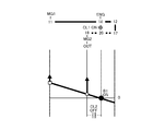
そのため、この発明の実施形態における駆動力制御装置は、蓄電装置47から第2モータ7に供給できる電力が低下することに伴う最大駆動力の低下を抑制できるように構成されている。その制御の一例を図16に示している。図16に示す制御例では、まず、車速Vが第1所定車速Vs1よりも高車速か否かを判断する(ステップS1)。このステップS1における第1所定車速Vs1は、蓄電装置47から出力可能な電力が低下したとしても、蓄電装置47から第2モータ7に充分な電力を供給できる場合と同等の駆動力を得られる車速である。具体的には、第2モータ7の特性に応じた第2モータ7の出力トルクが第2モータ7も回転数に関わらず一定となる基底速度に基づいた車速である。この基底速度は、第2モータ7に供給可能な電力が低下するに連れて低速になる。したがって、第1所定車速Vs1は、蓄電装置47から第2モータ7に供給できる電力に応じて定めることができる。なお、第1所定車速Vs1は、例えば、蓄電装置47から出力可能な電力が下限電力まで低下したとしても、蓄電装置47から第2モータ7に充分な電力を供給できる場合と同等の駆動力を得られる車速を固定値として採用してもよい。この第1所定車速Vs1が、この発明の実施形態における「所定車速」に相当する。
Therefore, the driving force control apparatus according to the embodiment of the present invention is configured to suppress a decrease in the maximum driving force that accompanies a decrease in the power that can be supplied from
車速Vが第1所定車速Vs1よりも高車速であることによりステップS1で肯定的に判断された場合は、蓄電装置47から第2モータ7に供給できる電力が、HV Loモードを設定した場合に、HV Hiモードを設定した場合よりも駆動力が低下する程度まで低下しているか否かを判断する。蓄電装置47から第2モータ7に供給できる電力は、蓄電装置47の出力可能電力や、第2電力制御装置46の耐久性の低下を抑制するための制限電力などに基づいて定めることができる。また、蓄電装置47の出力可能電力は、蓄電装置47の充電残量や蓄電装置47の温度に応じて定められている。ここに示す例では、上記の判断する一例として、蓄電装置47の出力可能電力が、第1閾値W1よりも少ないか否かを判断している(ステップS2)。第1閾値W1が、この発明の実施形態における「所定値」に相当する。なお、第1閾値W1は、実験やシミュレーションなどに基づいて予め定めることができる。
When the vehicle speed V is higher than the first predetermined vehicle speed Vs1 and a positive determination is made in step S1, the power that can be supplied from the
第1閾値W1は、例えば、HV Hiモードを設定している場合に、第1モータ6と蓄電装置47とから供給される電力により第2モータ7が定格トルクを出力することができること、およびHV Loモードを設定している場合にリングギヤ18に伝達されるトルクから、HV Hiモードを設定している場合にリングギヤ18に伝達されるトルクを減算した値が、第2モータ7の定格トルクから、HV Loモードを設定している場合における第2モータ7の出力トルク(第1モータ6と蓄電装置47とから供給される電力に基づくトルク)を減算した値よりも小さくなることとの二つの条件を満たす蓄電装置47の出力電力に定めることができる。すなわち、HV Loモードを設定することにより、リングギヤ18に伝達されるトルク差以上に、第2モータ7の出力トルクの低下量が大きくなる電力量を第1閾値W1として定めることができる。
The first threshold value W1 is, for example, that the
または、蓄電装置47の出力可能電力毎に、HV Hiモードを設定した場合の最大駆動力と、HV Loモードを設定した場合の最大駆動力とを予め演算や実験などに基づいて求めておき、HV Loモードを設定した場合の最大駆動力が、HV Hiモードを設定した場合の最大駆動力以下となる蓄電装置47の出力可能電力を、第1閾値W1として求めてもよい。さらに、第1閾値W1は、現実にHV Loモードを設定した場合の最大駆動力がHV Hiモードを設定した場合の最大駆動力よりも小さくなる値であるものに限らず、温度条件などが悪化した場合を考慮して定めてもよい。すなわち、現実にHV Loモードを設定した場合の最大駆動力がHV Hiモードを設定した場合の最大駆動力よりも小さくなる蓄電装置47の出力可能電力よりも大きい値に定めてもよい。
Alternatively, for each outputable power of the
蓄電装置47の出力可能電力が、第1閾値W1よりも少なくステップS2で肯定的に判断された場合は、HV Loモードを設定することを制限して(ステップS3)、このルーチンを一旦終了する。このステップS3における制限とは、蓄電装置47からの出力可能電力が第1閾値W1よりも小さい場合に、一律にHV Loモードを設定することを禁止するものではないことを意味している。例えば、図11や図12に示すマップに基づいて走行モードを設定する場合において、HV Hiモードや直結モードからHV Loモードに切り替える条件が成立した場合であっても、所定時間経過するまで、または第2モータ7の回転数が基底速度以下となる車速に低下するまで、現在設定されている走行モード(HV Hiモードまたは直結モード)を維持するなどとしてもよい。または、HV Hiモードや直結モードからHV Loモードに切り替えたとしても要求駆動力を充足することができる場合には、HV Loモードを設定することとしてもよい。あるいは、現状、HV Loモードが設定され、そのままHV Loモードで要求駆動力を充足することができる場合には、HV LoモードからHV Hiモードや直結モードに切り替えなくてもよい。
When the power that can be output from the
一方、車速Vが第1所定車速Vs1よりも高車速であり、または蓄電装置47の出力可能電力が第1閾値W1以上であることにより、ステップS1やステップS2で否定的に判断された場合には、HV Loモードを設定することを制限しているか否かを判断する(ステップS4)。このステップS4は、以前にステップS3が実行されるとともに、その制限が解除されていないか否かに基づいて判断することができる。具体的には、例えば、ステップS3を実行した場合に、HV Loモードを設定することを制限していることを判断するためのフラグをオンに切り替え、かつ後述するステップS6を実行した場合に、そのフラグをオフに切り替えるように構成し、ステップS4では、そのフラグがオンであるか否かに基づいて判断することができる。
On the other hand, when the vehicle speed V is higher than the first predetermined vehicle speed Vs1 or the output possible electric power of the
HV Loモードを設定することを制限していることによりステップS4で肯定的に判断された場合には、車速Vが第2所定車速Vs2よりも低車速か否かを判断する(ステップS5)。このステップS5は、HV Loモードを設定することの制限を解除してもよいか否かを判断するためのステップである。したがって、第2モータ7の回転数が、基底速度以下となっているか否かを判断する。なお、HV Loモードを設定することを制限するか否かの判断が頻繁に切り替わることを抑制するために、第2所定車速Vs2は、第1所定車速Vs1よりも低車速に定められている。
If the determination in step S4 is affirmative because the setting of the HV Lo mode is restricted, it is determined whether or not the vehicle speed V is lower than the second predetermined vehicle speed Vs2 (step S5). This step S5 is a step for determining whether or not the restriction on setting the HV Lo mode may be released. Therefore, it is determined whether or not the rotation speed of the
車速Vが第2所定車速Vs2よりも低車速であることによりステップS5で肯定的に判断された場合には、HV Loモードを設定することの制限を解除して(ステップS6)、このルーチンを一旦終了する。それとは反対に、車速Vが第2所定車速Vs2以上であることにより、ステップS5で否定的に判断された場合には、蓄電装置47からの出力可能電力が、第2閾値W2よりも大きいか否かを判断する(ステップS7)。このステップS7もステップS5と同様に、HV Loモードを設定することの制限を解除してもよいか否かを判断するためのステップである。したがって、HV Loモードを設定した場合の最大駆動力が、HV Hiモードを設定した場合の最大駆動力よりも大きい駆動力とすることができる電力を、蓄電装置47から出力できるか否かを判断する。なお、HV Loモードを設定することを制限するか否かの判断が頻繁に切り替わることを抑制するために、第2閾値W2は、第1閾値W1よりも大きな値に定められている。
If the vehicle speed V is lower than the second predetermined vehicle speed Vs2 and affirmative determination is made in step S5, the restriction on setting the HV Lo mode is released (step S6), and this routine is executed. Exit once. On the other hand, if the vehicle speed V is greater than or equal to the second predetermined vehicle speed Vs2, and if a negative determination is made in step S5, is the outputable power from the
蓄電装置47からの出力可能電力が、第2閾値W2よりも大きいことによりステップS7で肯定的に判断された場合には、ステップS6に移行する。すなわち、HV Loモードを設定することの制限を解除する。それとは反対に、蓄電装置47からの出力可能電力が、第2閾値W2以下であることによりステップS7で否定的に判断された場合には、そのままこのルーチンを一旦終了する。すなわち、HV Loモードを設定することの制限を維持する。
If the power that can be output from the
つぎに、停車時から所定車速まで加速した後に減速した場合における、蓄電装置47の出力可能電力の変化と、HV Loモードを設定することの制限の有無とを、図17に示すタイムチャートを参照して説明する。なお、図17には、車速、蓄電装置47の温度、蓄電装置47から出力可能な電力、蓄電装置47の充電残量(SOC)、HV Loモードを設定することの制限の有無の変化を示している。
Next, refer to the time chart shown in FIG. 17 for the change in the power that can be output from the
図17に示す例では、t0時点で走行し始め、t4時点で所定車速に到達し、その後、減速している。したがって、車速は、t0時点からt4時点に向けて次第に増大し、t4時点以降では、次第に低下している。また、蓄電装置47の電力を走行のために使用していることにより、t0時点から蓄電装置47の充電残量が次第に低下し、所定車速到達後は、要求駆動力が低下することに伴って蓄電装置47の充電残量が緩やかに低下する。また、蓄電装置47から電力を出力することなどに伴って、蓄電装置47の温度は、t0時点から次第に増大している。蓄電装置47の最大出力電力は、蓄電装置47の充電残量と、蓄電装置47の温度とに基づいて定まるため、図17に示す例では、t0時点からt3時点までの間は、蓄電装置47の温度上昇を主な理由として、蓄電装置47の最大出力が増大し、その後、t5時点までの間は、蓄電装置47の温度の上限や蓄電装置47の充電残量の低下などを要因として、蓄電装置47の最大出力電力がほぼ一定に維持され、t5時点以降では、最大出力電力が次第に低下している。
In the example shown in FIG. 17, the vehicle starts traveling at time t0, reaches a predetermined vehicle speed at time t4, and then decelerates. Accordingly, the vehicle speed gradually increases from the time t0 to the time t4, and gradually decreases after the time t4. Further, since the electric power of the
このような場合において、t1時点で、第1所定車速Vs1よりも高車速になるとともに、その際における蓄電装置47の最大出力電力が第1閾値W1未満であることにより、上記ステップS1やステップS2で肯定的に判断されるため、HV Loモードを設定することが制限される。
In such a case, when the vehicle speed becomes higher than the first predetermined vehicle speed Vs1 at time t1, and the maximum output power of the
t2時点では、蓄電装置47の出力可能電力が第2閾値W2よりも大きくなることにより、上記ステップS7で肯定的に判断されるため、HV Loモードを設定することの制限が解除される。一方、t5時点から蓄電装置47の出力可能電力が低下し、その出力可能電力が第1閾値W1を下回ると(t6時点)、HV Loモードを設定することが制限される。なお、図17に示す例では、t6時点での車速は、第1所定車速V1よりも高車速であるため、上記ステップS1で肯定的に判断される。
At time t2, since the power that can be output from the
上述したようにHV Loモードを設定した場合よりもHV Hiモードを設定した場合の方が最大駆動力が大きくなる程度まで、蓄電装置47の出力可能電力が低下した場合に、HV Loモードを設定することを制限することにより、蓄電装置47の出力可能電力に基づいた駆動力の低下量を低減すること、または駆動力が不足することを抑制することができる。また、低車速域(第1所定車速Vs1や第2所定車速Vs2以下の車速)では、HV Loモードを設定することを制限しないことにより、低車速域における最大駆動力が制限されることを抑制することができる。具体的には、低車速域では、図15にLo1で示す駆動力を出力することができ、低車速域以外では、図15にHi2で示す駆動力を出力することができる。
Set the HV Lo mode when the output power of the
なお、この発明の実施形態における駆動力制御装置は、図16に示す制御例におけるステップS1やステップS5を実行しないものであってもよい。すなわち、車速に基づいてHV Loモードを設定することを制限するか否かを判断しなくてもよい。その場合には、ステップS4で肯定的に判断された後に、ステップS7を判断すればよい。 Note that the driving force control apparatus in the embodiment of the present invention may not execute Step S1 or Step S5 in the control example shown in FIG. That is, it is not necessary to determine whether to limit the setting of the HV Lo mode based on the vehicle speed. In that case, step S7 may be determined after a positive determination is made in step S4.
また、HV Loモードを設定した際のエンジン5の上限出力が大きくなるに連れて第1閾値W1が小さくなるように構成されていてもよい。これは、エンジン5の上限出力が大きくなるに連れて第1モータ6の発電量が多くなるため、蓄電装置47から第2モータ7に供給できる電力が小さいとしても、第2モータ7に充分な電力が供給されるためである。したがって、例えば、実験やシミュレーションなどに基づいて図18に示すマップを予め用意し、そのマップにおける第1閾値W1に基づいて、上記ステップS2を判断するように構成してもよい。なお、図18における横軸は、HV Loモードを設定した際のエンジン5の上限出力の大きさを示し、縦軸は、第1閾値W1の大きさを示している。
Alternatively, the first threshold value W1 may be configured to decrease as the upper limit output of the
さらに、上述したようにエンジン5の上限出力は、ピニオンギヤ13の許容回転数に基づいて求められる。このピニオンギヤ13の許容回転数は、ピニオンギヤ13の耐久性が低下することを抑制するために定められている。したがって、例えば、図19に示すようにピニオンギヤ13の温度が高温になるに連れて許容回転数を低回転数に定め、または図20に示すようにピニオンギヤ13に供給される潤滑油(潤滑媒体)の量が多くなるに連れて許容回転数を高回転数に定めてもよい。そのようにピニオンギヤ13の許容回転数を定めることにより、エンジン5の出力が過度に制限されることを抑制することができ、その結果、駆動力の低下量を低減すること、または駆動力が不足することを抑制することができる。なお、図19における横軸はピニオンギヤ13の温度を示し、縦軸はピニオンギヤ13の許容回転数を示し、図20における横軸はピニオンギヤ13に供給される潤滑油量を示し、縦軸は許容回転数を示している。また、ピニオンギヤ13の温度は、ピニオンギヤ13の近傍に温度センサを設け、その温度センサの検出値を採用してもよく、ピニオンギヤ13に作用するトルクの大きさから推定してもよく、第1駆動装置2の内部のオイルの温度から推定してもよい。
Further, as described above, the upper limit output of the
図16に示す制御例によりHV Loモードを設定することが制限されることにより、HV Hiモードや直結モードを設定することで最大駆動力が過度に低下することを抑制することができるものの、HV Hiモードや直結モードでは運転者が要求する駆動力を得られない可能性がある。そのため、蓄電装置47から第2モータ7に供給できる電力を、迅速に増大させること復帰させることが好ましい。そのため、この発明の実施形態における駆動力制御装置は、HV Loモードを設定することが制限されている間に、蓄電装置47の出力可能電力を増大させるなどの復帰制御を実行してもよい。
Although the setting of the HV Lo mode is restricted by the control example shown in FIG. 16, the maximum driving force can be prevented from excessively decreasing by setting the HV Hi mode or the direct connection mode. There is a possibility that the driving force requested by the driver cannot be obtained in the Hi mode or the direct connection mode. For this reason, it is preferable that power that can be supplied from the
図21には、その復帰制御の一例を示してある。この図21に示す復帰制御は、蓄電装置47が高温になることにより、蓄電装置47からの出力可能電力が制限された場合などに主に実行される。図21に示す例では、まず、HV Loモードを設定することが制限されているか否かを判断する(ステップS11)。このステップS11は、図16におけるステップS4と同様に判断することができる。
FIG. 21 shows an example of the return control. The return control shown in FIG. 21 is mainly executed when the power that can be output from the
HV Loモードを設定することが制限されていないことによりステップS11で否定的に判断された場合には、通常時用の指令信号に基づいて冷却ファンFを駆動して(ステップS12)、このルーチンを一旦終了する。それとは反対に、HV Loモードを設定することが制限されていることによりステップS11で肯定的に判断された場合には、復帰制御用の指令信号に基づいて冷却ファンFを駆動して(ステップS13)、このルーチンを一旦終了する。 If it is determined in step S11 that the setting of the HV Lo mode is not restricted, the cooling fan F is driven based on the normal time command signal (step S12), and this routine is executed. Is temporarily terminated. On the other hand, if the determination in step S11 is affirmative because the setting of the HV Lo mode is restricted, the cooling fan F is driven based on the return control command signal (step S11). S13) This routine is once terminated.
図22には、冷却ファンFを駆動するための指令信号の一例を示しており、横軸に蓄電装置47の温度をとり、縦軸に冷却ファンFに向けて出力される電流値の大きさをとっている。また、図22における実線は復帰制御時に出力される電流値を示し、破線は通常時に出力される電流値を示している。図22に示すように復帰制御時には、蓄電装置47の温度が比較的低温のうちから冷却ファンFに通電されるとともに、通常時よりも大きな電流が通電される。その結果、蓄電装置47を迅速に冷却することができるため、蓄電装置47からの出力電力の制限を迅速に緩和することができる。つまり、HV Loモードを設定することの制限を迅速に解除することができる。なお、冷却ファンFのような空冷式の冷却装置に限らず、水冷式の冷却装置であってもよく、その場合には、HV Loモードを設定することが制限されている場合に、冷却水の流量を増大させるなどとしてもよい。つまり、HV Loモードが設定されている場合に、蓄電装置47の冷却量を増加させることができればよい。
FIG. 22 shows an example of a command signal for driving the cooling fan F. The horizontal axis indicates the temperature of the
また、蓄電装置47の充電残量が低下するに連れて、蓄電装置47の出力可能電力が低下して、HV Loモードを設定することが制限される場合がある。そのような場合に、迅速に蓄電装置47の出力可能電力を増大させるため、つまり、蓄電装置47の充電残量を増大させるための復帰制御の一例を図23に示している。
Further, as the remaining charge amount of the
図23に示す復帰制御は、エンジン5を始動する頻度を増大させることで、蓄電装置47を充電するように構成されている。具体的には、車両に要求されるパワーが比較的小さい状態でエンジン5が始動するように構成されている。
The return control shown in FIG. 23 is configured to charge the
図23に示す例では、まず、上記ステップS11と同様に、HV Loモードを設定することが制限されているか否かを判断する(ステップS21)。HV Loモードを設定することが制限されていないことによりステップS21で否定的に判断された場合には、エンジン5を始動する閾値を通常時に設定される第1始動閾値に設定する(ステップS22)。それとは反対に、HV Loモードを設定することが制限されていることによりステップS21で否定的に判断された場合には、エンジン5を始動する閾値を第1始動閾値よりも小さい値の第2始動閾値に設定する(ステップS23)。
In the example shown in FIG. 23, first, as in step S11, it is determined whether or not the setting of the HV Lo mode is restricted (step S21). If a negative determination is made in step S21 because the setting of the HV Lo mode is not restricted, the threshold value for starting the
このようにHV Loモードを設定することが制限されている場合に、エンジン5を始動する頻度を増大させることにより、エンジン5から出力された動力を第1モータ6により回生する頻度が増大する。その結果、蓄電装置47の充電残量を迅速に増大させることができ、蓄電装置47からの出力電力の制限を迅速に緩和することができる。つまり、HV Loモードを設定することの制限を迅速に解除することができる。
When the setting of the HV Lo mode is restricted in this way, the frequency at which the power output from the
この発明は、上述した各実施例に限定されないのであって、この発明の目的を逸脱しない範囲で適宜に変更することができる。例えば、対象とすることができるハイブリッド車両は、エンジン5から第1モータ側に伝達する動力と出力側に伝達する動力との比率を変更することができる伝動機構を備えていればよく、その構成は上述した実施例に限定されない。すなわち、以下に記載するように構成されたハイブリッド車両は、少なくともこの発明で対象とするハイブリッド車両に含まれる。
The present invention is not limited to the above-described embodiments, and can be appropriately changed without departing from the object of the present invention. For example, the hybrid vehicle that can be the target only needs to include a transmission mechanism that can change the ratio of the power transmitted from the
すなわち、『エンジンが連結された入力用回転部材と発電機が連結された反力用回転部材と出力用回転部材との三つの回転部材と、前記三つの回転部材のうちのいずれか一つである第1回転部材が連結されている第1回転要素と前記三つの回転部材のうちの他のいずれか一つである第2回転部材が連結されている第2回転要素と第3回転要素とによって差動作用を行う第1差動機構と、前記三つの回転部材のうちの更に他の一つである第3回転部材が連結されている第4回転要素と前記第3回転要素に連結されている第5回転要素と第6回転要素とによって差動作用を行う第2差動機構と、前記第6回転要素と前記第1回転要素または前記第2回転要素とを連結し、またその連結を解く第1係合機構と、前記第4回転要素と前記第5回転要素と前記第6回転要素とのうちの少なくともいずれか二つの回転要素を連結し、またその連結を解く第2係合機構とを有するハイブリッド車両』は、この発明で対象とするハイブリッド車両に含まれる。 That is, “in any one of the three rotating members of the rotating member for input to which the engine is connected, the rotating member for reaction force to which the generator is connected, and the rotating member for output, and the three rotating members. A second rotating element and a third rotating element to which a first rotating element to which a certain first rotating member is connected and a second rotating member that is any one of the three rotating members are connected; A first differential mechanism that performs a differential action, and a fourth rotary element to which a third rotary member, which is another one of the three rotary members, is connected, and the third rotary element. A second differential mechanism that performs a differential action by the fifth rotating element and the sixth rotating element, and the sixth rotating element and the first rotating element or the second rotating element, and the connection A first engaging mechanism for solving the problem, the fourth rotating element and the fifth rotating element The sixth connecting at least any two rotary elements of the rotating element, also hybrid vehicle "as a second engagement mechanism for solving the connection, it included in the hybrid vehicle to which the present invention.
1R,1L…前輪、 2…第1駆動装置、 5…エンジン、 6…第1モータ、 7…第2モータ、 8…動力分割機構、 9…分割部、 10…変速部、 11,17,32…サンギヤ、 12,18,26,33,42…リングギヤ、 13,19,34…ピニオンギヤ、 14,20,35…キャリヤ、 30…リアモータ、 47…蓄電装置、 CL1…第1クラッチ機構、 CL2…第2クラッチ機構、 CL3…第3クラッチ機構、 48…ECU、 49…統合ECU、 50…MG ECU、 51…エンジンECU、 52…クラッチECU、 F…冷却ファン。
DESCRIPTION OF
Claims (10)
前記エンジンから出力された動力の一部を電力に変換可能な第1回転機と、
前記エンジンから出力された動力を前記第1回転機側と出力部材側とに分割するとともに、前記第1回転機側に伝達する動力と前記出力部材側に伝達する動力との比率が第1比率となる第1モードおよび前記第1モードよりも前記出力部材側に伝達する動力の割合が小さい第2比率となる第2モードを設定可能な伝動機構と、
蓄電装置と、
前記第1回転機により変換された電力と前記蓄電装置の電力との少なくともいずれか一方の電力が供給されることにより動力を出力する第2回転機と
を備え、
前記エンジンから上限出力を出力するとともに、前記第1回転機により変換された前記電力と前記蓄電装置から前記第2回転機に供給可能な上限電力とを前記第2回転機に供給して前記第2回転機から動力を出力することにより、車両が最大駆動力を発生させるように構成されたハイブリッド車両の駆動力制御装置において、
前記伝動機構を制御するコントローラを備え、
前記コントローラは、
前記蓄電装置から前記第2回転機に供給可能な上限電力が所定値未満の場合に、前記第1モードを設定することを制限するように構成されている
ことを特徴とするハイブリッド車両の駆動力制御装置。
Engine,
A first rotating machine capable of converting part of the power output from the engine into electric power;
The power output from the engine is divided into the first rotating machine side and the output member side, and the ratio of the power transmitted to the first rotating machine side and the power transmitted to the output member side is a first ratio. A transmission mechanism capable of setting a first mode to be set and a second mode in which a ratio of power transmitted to the output member side is smaller than that of the first mode is a second ratio;
A power storage device;
A second rotating machine that outputs power by being supplied with at least one of the electric power converted by the first rotating machine and the electric power of the power storage device;
An upper limit output is output from the engine, and the electric power converted by the first rotating machine and an upper limit electric power that can be supplied from the power storage device to the second rotating machine are supplied to the second rotating machine. In the driving force control apparatus for a hybrid vehicle configured to generate the maximum driving force by outputting power from the two-rotor machine,
A controller for controlling the transmission mechanism;
The controller is
A driving force of a hybrid vehicle configured to limit the setting of the first mode when an upper limit power that can be supplied from the power storage device to the second rotating machine is less than a predetermined value. Control device.
前記所定値は、前記第1モードを設定した場合における前記最大駆動力が、前記第2モードを設定した場合における前記最大駆動力よりも小さくなる電力値を含む
ことを特徴とするハイブリッド車両の駆動力制御装置。
In the hybrid vehicle driving force control device according to claim 1,
The predetermined value includes an electric power value in which the maximum driving force when the first mode is set is smaller than the maximum driving force when the second mode is set. Force control device.
前記所定値は、前記エンジンの上限出力が大きくなるに連れて小さい値に設定される
ことを特徴とするハイブリッド車両の駆動力制御装置。
In the hybrid vehicle driving force control device according to claim 1 or 2,
The driving force control apparatus for a hybrid vehicle, wherein the predetermined value is set to a smaller value as the upper limit output of the engine increases.
前記エンジンから出力可能な上限出力は、前記エンジンの上限回転数と前記エンジンから出力可能な最大トルクとの積で求められる動力であり、
前記第1モードを設定した場合における前記エンジンの上限回転数は、前記第2モードを設定した場合における前記エンジンの上限回転数よりも低回転数になる
ことを特徴とするハイブリッド車両の駆動力制御装置。
In the hybrid vehicle driving force control device according to any one of claims 1 to 3,
The upper limit output that can be output from the engine is power determined by the product of the upper limit rotational speed of the engine and the maximum torque that can be output from the engine,
The driving force control of a hybrid vehicle, wherein the upper limit number of revolutions of the engine when the first mode is set is lower than the upper limit number of revolutions of the engine when the second mode is set. apparatus.
前記伝動機構は、複数の回転部材を有し、
前記複数の回転部材のうちのいずれか一つの対象回転部材の許容回転数が高回転数になるに連れて、前記エンジンの上限回転数が高回転数になる
ことを特徴とするハイブリッド車両の駆動力制御装置。
The driving force control apparatus for a hybrid vehicle according to claim 4,
The transmission mechanism has a plurality of rotating members,
The hybrid vehicle drive characterized in that the upper limit number of rotations of the engine becomes higher as the allowable number of rotations of any one of the plurality of rotation members becomes higher. Force control device.
前記許容回転数は、前記対象回転部材の温度が高温になるに連れて低回転数になり、前記対象回転部材に供給される潤滑媒体の量が多くなるに連れて高回転数になる
ことを特徴とするハイブリッド車両の駆動力制御装置。
The driving force control apparatus for a hybrid vehicle according to claim 5,
The allowable rotational speed becomes lower as the temperature of the target rotational member becomes higher, and becomes higher as the amount of the lubricating medium supplied to the target rotational member increases. A hybrid vehicle driving force control device.
前記コントローラは、
車速が所定車速以上の場合に、前記第1モードを設定することを制限するように構成されている
ことを特徴とするハイブリッド車両の駆動力制御装置。
The driving force control apparatus for a hybrid vehicle according to any one of claims 1 to 6,
The controller is
A driving force control device for a hybrid vehicle configured to limit the setting of the first mode when the vehicle speed is equal to or higher than a predetermined vehicle speed.
前記コントローラは、
前記第1モードを設定することが制限されている間に、前記蓄電装置から前記第2回転機に供給可能な上限電力を増大させる復帰制御を実行するように構成されている
ことを特徴とするハイブリッド車両の駆動力制御装置。
The driving force control apparatus for a hybrid vehicle according to any one of claims 1 to 6,
The controller is
While the setting of the first mode is restricted, a return control for increasing an upper limit power that can be supplied from the power storage device to the second rotating machine is performed. A driving force control device for a hybrid vehicle.
前記蓄電装置は、前記蓄電装置の温度が所定温度以上となることにより前記蓄電装置から出力することができる電力が制限されるように構成され、
前記蓄電装置を冷却する冷却装置を備え、
前記復帰制御は、前記第1モードを設定することが制限していない場合と比較して、前記冷却装置における前記蓄電装置の冷却量を増加する制御を含む
ことを特徴とするハイブリッド車両の駆動力制御装置。
The driving force control apparatus for a hybrid vehicle according to claim 8,
The power storage device is configured such that power that can be output from the power storage device is limited when a temperature of the power storage device is equal to or higher than a predetermined temperature.
A cooling device for cooling the power storage device,
The return control includes a control for increasing a cooling amount of the power storage device in the cooling device as compared with a case where setting of the first mode is not limited. Control device.
前記車両は、前記エンジンと前記第2回転機とから走行のための動力を出力して走行するHV走行モードと、前記エンジンから走行のための動力を出力せずに前記第2回転機から走行のための動力を出力して走行するEV走行モードとを選択可能に構成され、
前記エンジンは、前記車両に要求される動力が所定動力以上の場合に、前記エンジンを始動するように構成され、
前記復帰制御は、前記第1モードを設定することが制限されていない場合と比較して、前記所定動力を小さくする制御を含む
ことを特徴とするハイブリッド車両の駆動力制御装置。 In the hybrid vehicle driving force control device according to claim 8 or 9,
The vehicle travels from the second rotating machine without outputting the power for traveling from the engine and the HV traveling mode in which the engine and the second rotating machine output power for traveling. It is configured to be able to select an EV traveling mode in which power is output for traveling
The engine is configured to start the engine when the power required for the vehicle is equal to or greater than a predetermined power;
The return control includes a control for reducing the predetermined power as compared with a case where setting of the first mode is not restricted.
Priority Applications (4)
| Application Number | Priority Date | Filing Date | Title |
|---|---|---|---|
| JP2017153836A JP6662359B2 (en) | 2017-08-09 | 2017-08-09 | Driving force control device for hybrid vehicle |
| EP17211168.4A EP3441249B1 (en) | 2017-08-09 | 2017-12-29 | Drive force control system for hybrid vehicle |
| US16/043,646 US10759410B2 (en) | 2017-08-09 | 2018-07-24 | Drive force control system for hybrid vehicle |
| CN201810894360.9A CN109383267B (en) | 2017-08-09 | 2018-08-08 | Driving force control device for hybrid vehicle |
Applications Claiming Priority (1)
| Application Number | Priority Date | Filing Date | Title |
|---|---|---|---|
| JP2017153836A JP6662359B2 (en) | 2017-08-09 | 2017-08-09 | Driving force control device for hybrid vehicle |
Publications (2)
| Publication Number | Publication Date |
|---|---|
| JP2019031214A true JP2019031214A (en) | 2019-02-28 |
| JP6662359B2 JP6662359B2 (en) | 2020-03-11 |
Family
ID=60856974
Family Applications (1)
| Application Number | Title | Priority Date | Filing Date |
|---|---|---|---|
| JP2017153836A Expired - Fee Related JP6662359B2 (en) | 2017-08-09 | 2017-08-09 | Driving force control device for hybrid vehicle |
Country Status (4)
| Country | Link |
|---|---|
| US (1) | US10759410B2 (en) |
| EP (1) | EP3441249B1 (en) |
| JP (1) | JP6662359B2 (en) |
| CN (1) | CN109383267B (en) |
Families Citing this family (5)
| Publication number | Priority date | Publication date | Assignee | Title |
|---|---|---|---|---|
| JP6863231B2 (en) * | 2017-10-30 | 2021-04-21 | トヨタ自動車株式会社 | Hybrid vehicle control device |
| JP7215967B2 (en) * | 2019-06-18 | 2023-01-31 | トヨタ自動車株式会社 | Hybrid vehicle control device |
| CN113715804B (en) * | 2020-05-22 | 2024-04-12 | 广汽埃安新能源汽车有限公司 | Controller of vehicle with hybrid power coupling system, control method and vehicle |
| JP7287351B2 (en) * | 2020-06-01 | 2023-06-06 | トヨタ自動車株式会社 | Hybrid vehicle control device |
| CN114435335B (en) * | 2022-02-09 | 2023-12-15 | 浙江吉利控股集团有限公司 | Power system control method and system of hybrid power vehicle and vehicle |
Citations (10)
| Publication number | Priority date | Publication date | Assignee | Title |
|---|---|---|---|---|
| JPH0658381A (en) * | 1992-08-04 | 1994-03-01 | Aisin Seiki Co Ltd | Planetary gear system of automatic transmission device |
| JPH0946821A (en) * | 1995-05-24 | 1997-02-14 | Toyota Motor Corp | Hybrid electric vehicle |
| JP2000050412A (en) * | 1998-07-24 | 2000-02-18 | Mazda Motor Corp | Hybrid automobile |
| JP2004297950A (en) * | 2003-03-27 | 2004-10-21 | Toyota Motor Corp | Hybrid vehicle drive system |
| JP2005063682A (en) * | 2003-08-11 | 2005-03-10 | Nissan Motor Co Ltd | Battery cooling control device |
| US20090115349A1 (en) * | 2007-11-07 | 2009-05-07 | Gm Global Technology Operations, Inc. | Method and control architecture to determine motor torque split in fixed gear operation for a hybrid powertrain system |
| WO2013076851A1 (en) * | 2011-11-24 | 2013-05-30 | トヨタ自動車株式会社 | Gear shift indicating device for hybrid vehicle |
| JP2014104882A (en) * | 2012-11-28 | 2014-06-09 | Toyota Motor Corp | Control apparatus of vehicle |
| JP2017007437A (en) * | 2015-06-18 | 2017-01-12 | トヨタ自動車株式会社 | Hybrid vehicle drive device |
| JP2017013741A (en) * | 2015-07-06 | 2017-01-19 | トヨタ自動車株式会社 | Hybrid-vehicular control apparatus |
Family Cites Families (20)
| Publication number | Priority date | Publication date | Assignee | Title |
|---|---|---|---|---|
| US6321144B1 (en) * | 2000-08-08 | 2001-11-20 | Ford Global Technologies, Inc. | Torque control strategy for management of rollback in a wheeled vehicle whose powertrain includes a rotary electric machine |
| JP3933106B2 (en) * | 2003-07-30 | 2007-06-20 | トヨタ自動車株式会社 | POWER OUTPUT DEVICE, ITS CONTROL METHOD, AND AUTOMOBILE |
| JP4049138B2 (en) * | 2004-08-23 | 2008-02-20 | トヨタ自動車株式会社 | Vehicle control device |
| JP4215043B2 (en) * | 2005-11-17 | 2009-01-28 | トヨタ自動車株式会社 | POWER OUTPUT DEVICE, VEHICLE MOUNTING THE SAME, AND METHOD FOR CONTROLLING POWER OUTPUT DEVICE |
| CN101007533B (en) * | 2006-01-26 | 2010-12-22 | 艾晓林 | Mechanical and electric hybrid power system and its control |
| JP4784478B2 (en) * | 2006-04-20 | 2011-10-05 | 株式会社デンソー | Control device for multiphase rotating electrical machine |
| JP5092694B2 (en) * | 2007-11-01 | 2012-12-05 | トヨタ自動車株式会社 | Control device for vehicle power transmission device |
| WO2009084359A1 (en) * | 2007-12-28 | 2009-07-09 | Aisin Aw Co., Ltd. | Rotating electric machine control system |
| JP2011152829A (en) * | 2010-01-26 | 2011-08-11 | Aisin Aw Co Ltd | Hybrid drive apparatus |
| JP5126628B2 (en) * | 2010-04-02 | 2013-01-23 | アイシン・エィ・ダブリュ株式会社 | Control device |
| JP5622038B2 (en) * | 2010-09-06 | 2014-11-12 | アイシン・エィ・ダブリュ株式会社 | Control device |
| JP5565627B2 (en) * | 2010-09-29 | 2014-08-06 | アイシン・エィ・ダブリュ株式会社 | Control device |
| JP5382467B2 (en) * | 2011-04-20 | 2014-01-08 | アイシン・エィ・ダブリュ株式会社 | Vehicle drive device |
| US9624992B2 (en) * | 2012-01-17 | 2017-04-18 | Aisin Aw Co., Ltd. | Control device for vehicle drive device |
| JP5892243B2 (en) * | 2012-05-22 | 2016-03-23 | トヨタ自動車株式会社 | Control device for hybrid vehicle |
| JP5892256B2 (en) * | 2012-09-14 | 2016-03-23 | トヨタ自動車株式会社 | Power transmission device and hybrid system for hybrid vehicle |
| CN104853969B (en) * | 2012-12-06 | 2017-06-20 | 丰田自动车株式会社 | Power transmission |
| JP5949692B2 (en) * | 2013-07-30 | 2016-07-13 | トヨタ自動車株式会社 | Hybrid system |
| US9415769B2 (en) * | 2014-09-25 | 2016-08-16 | Ford Global Technologies, Llc | System and method for controlling a powertrain in a vehicle |
| JP6380304B2 (en) * | 2015-09-03 | 2018-08-29 | トヨタ自動車株式会社 | Hybrid car |
-
2017
- 2017-08-09 JP JP2017153836A patent/JP6662359B2/en not_active Expired - Fee Related
- 2017-12-29 EP EP17211168.4A patent/EP3441249B1/en not_active Not-in-force
-
2018
- 2018-07-24 US US16/043,646 patent/US10759410B2/en not_active Expired - Fee Related
- 2018-08-08 CN CN201810894360.9A patent/CN109383267B/en not_active Expired - Fee Related
Patent Citations (10)
| Publication number | Priority date | Publication date | Assignee | Title |
|---|---|---|---|---|
| JPH0658381A (en) * | 1992-08-04 | 1994-03-01 | Aisin Seiki Co Ltd | Planetary gear system of automatic transmission device |
| JPH0946821A (en) * | 1995-05-24 | 1997-02-14 | Toyota Motor Corp | Hybrid electric vehicle |
| JP2000050412A (en) * | 1998-07-24 | 2000-02-18 | Mazda Motor Corp | Hybrid automobile |
| JP2004297950A (en) * | 2003-03-27 | 2004-10-21 | Toyota Motor Corp | Hybrid vehicle drive system |
| JP2005063682A (en) * | 2003-08-11 | 2005-03-10 | Nissan Motor Co Ltd | Battery cooling control device |
| US20090115349A1 (en) * | 2007-11-07 | 2009-05-07 | Gm Global Technology Operations, Inc. | Method and control architecture to determine motor torque split in fixed gear operation for a hybrid powertrain system |
| WO2013076851A1 (en) * | 2011-11-24 | 2013-05-30 | トヨタ自動車株式会社 | Gear shift indicating device for hybrid vehicle |
| JP2014104882A (en) * | 2012-11-28 | 2014-06-09 | Toyota Motor Corp | Control apparatus of vehicle |
| JP2017007437A (en) * | 2015-06-18 | 2017-01-12 | トヨタ自動車株式会社 | Hybrid vehicle drive device |
| JP2017013741A (en) * | 2015-07-06 | 2017-01-19 | トヨタ自動車株式会社 | Hybrid-vehicular control apparatus |
Also Published As
| Publication number | Publication date |
|---|---|
| CN109383267A (en) | 2019-02-26 |
| CN109383267B (en) | 2021-09-07 |
| JP6662359B2 (en) | 2020-03-11 |
| US20190047543A1 (en) | 2019-02-14 |
| US10759410B2 (en) | 2020-09-01 |
| EP3441249A1 (en) | 2019-02-13 |
| EP3441249B1 (en) | 2019-12-04 |
Similar Documents
| Publication | Publication Date | Title |
|---|---|---|
| JP6930414B2 (en) | Hybrid vehicle driving force control device | |
| CN109774698B (en) | Drive force control device for hybrid vehicle | |
| JP6024691B2 (en) | Control device for drive device for hybrid vehicle | |
| CN109383267B (en) | Driving force control device for hybrid vehicle | |
| KR102075890B1 (en) | Vehicle, and method of controlling vehicle | |
| JP2019081438A (en) | Device for controlling hybrid vehicle | |
| JP5907155B2 (en) | Control device for hybrid drive | |
| US9724991B2 (en) | Hybrid vehicle driving apparatus | |
| JP2019108056A (en) | Driving force control device of vehicle | |
| JP6958455B2 (en) | Vehicle control device | |
| JP6965799B2 (en) | Hybrid vehicle control device | |
| JP2019073173A (en) | Hybrid-vehicular drive force control apparatus | |
| JP2020097334A (en) | Control device of hybrid vehicle | |
| JP2019138411A (en) | Drive controller of vehicle | |
| JP7172894B2 (en) | vehicle controller | |
| JP7215967B2 (en) | Hybrid vehicle control device | |
| JP6897519B2 (en) | Transmission controller | |
| JP2022049811A (en) | Hybrid vehicle control device | |
| JP2022037659A (en) | Vehicle control device | |
| JP7081439B2 (en) | Hybrid vehicle control device | |
| US20220063586A1 (en) | Vehicle control system | |
| JP2020075682A (en) | Control device for hybrid vehicle | |
| JP2022023569A (en) | Hybrid vehicle control device | |
| JP2020090206A (en) | Control device for hybrid vehicle |
Legal Events
| Date | Code | Title | Description |
|---|---|---|---|
| A621 | Written request for application examination |
Free format text: JAPANESE INTERMEDIATE CODE: A621 Effective date: 20181218 |
|
| A977 | Report on retrieval |
Free format text: JAPANESE INTERMEDIATE CODE: A971007 Effective date: 20191017 |
|
| A131 | Notification of reasons for refusal |
Free format text: JAPANESE INTERMEDIATE CODE: A131 Effective date: 20191029 |
|
| A521 | Request for written amendment filed |
Free format text: JAPANESE INTERMEDIATE CODE: A821 Effective date: 20191120 Free format text: JAPANESE INTERMEDIATE CODE: A523 Effective date: 20191120 |
|
| RD02 | Notification of acceptance of power of attorney |
Free format text: JAPANESE INTERMEDIATE CODE: A7422 Effective date: 20191120 |
|
| TRDD | Decision of grant or rejection written | ||
| A01 | Written decision to grant a patent or to grant a registration (utility model) |
Free format text: JAPANESE INTERMEDIATE CODE: A01 Effective date: 20200114 |
|
| A61 | First payment of annual fees (during grant procedure) |
Free format text: JAPANESE INTERMEDIATE CODE: A61 Effective date: 20200127 |
|
| R151 | Written notification of patent or utility model registration |
Ref document number: 6662359 Country of ref document: JP Free format text: JAPANESE INTERMEDIATE CODE: R151 |
|
| LAPS | Cancellation because of no payment of annual fees |