JP2019073173A - Hybrid-vehicular drive force control apparatus - Google Patents
Hybrid-vehicular drive force control apparatus Download PDFInfo
- Publication number
- JP2019073173A JP2019073173A JP2017200812A JP2017200812A JP2019073173A JP 2019073173 A JP2019073173 A JP 2019073173A JP 2017200812 A JP2017200812 A JP 2017200812A JP 2017200812 A JP2017200812 A JP 2017200812A JP 2019073173 A JP2019073173 A JP 2019073173A
- Authority
- JP
- Japan
- Prior art keywords
- mode
- power
- motor
- output
- storage device
- Prior art date
- Legal status (The legal status is an assumption and is not a legal conclusion. Google has not performed a legal analysis and makes no representation as to the accuracy of the status listed.)
- Pending
Links
- 230000007246 mechanism Effects 0.000 claims description 95
- 230000005540 biological transmission Effects 0.000 claims description 44
- 238000006243 chemical reaction Methods 0.000 claims description 18
- 238000010248 power generation Methods 0.000 claims description 7
- 230000006866 deterioration Effects 0.000 abstract description 2
- 230000009467 reduction Effects 0.000 description 23
- 230000008878 coupling Effects 0.000 description 16
- 238000010168 coupling process Methods 0.000 description 16
- 238000005859 coupling reaction Methods 0.000 description 16
- 230000008859 change Effects 0.000 description 15
- 230000007423 decrease Effects 0.000 description 12
- 238000010586 diagram Methods 0.000 description 9
- 238000001816 cooling Methods 0.000 description 5
- 230000009977 dual effect Effects 0.000 description 4
- 238000002474 experimental method Methods 0.000 description 3
- 230000035945 sensitivity Effects 0.000 description 3
- 230000003321 amplification Effects 0.000 description 2
- 238000004364 calculation method Methods 0.000 description 2
- 150000001875 compounds Chemical class 0.000 description 2
- 238000013016 damping Methods 0.000 description 2
- 230000003247 decreasing effect Effects 0.000 description 2
- 239000000446 fuel Substances 0.000 description 2
- 230000012447 hatching Effects 0.000 description 2
- 238000000034 method Methods 0.000 description 2
- 238000003199 nucleic acid amplification method Methods 0.000 description 2
- 230000008569 process Effects 0.000 description 2
- HBBGRARXTFLTSG-UHFFFAOYSA-N Lithium ion Chemical compound [Li+] HBBGRARXTFLTSG-UHFFFAOYSA-N 0.000 description 1
- 230000004323 axial length Effects 0.000 description 1
- 239000003990 capacitor Substances 0.000 description 1
- 230000000779 depleting effect Effects 0.000 description 1
- 230000009699 differential effect Effects 0.000 description 1
- 238000005265 energy consumption Methods 0.000 description 1
- 230000006872 improvement Effects 0.000 description 1
- 229910001416 lithium ion Inorganic materials 0.000 description 1
- 230000001050 lubricating effect Effects 0.000 description 1
- 230000002093 peripheral effect Effects 0.000 description 1
- 230000001172 regenerating effect Effects 0.000 description 1
- 230000004044 response Effects 0.000 description 1
- 238000004088 simulation Methods 0.000 description 1
Images


Classifications
-
- Y—GENERAL TAGGING OF NEW TECHNOLOGICAL DEVELOPMENTS; GENERAL TAGGING OF CROSS-SECTIONAL TECHNOLOGIES SPANNING OVER SEVERAL SECTIONS OF THE IPC; TECHNICAL SUBJECTS COVERED BY FORMER USPC CROSS-REFERENCE ART COLLECTIONS [XRACs] AND DIGESTS
- Y02—TECHNOLOGIES OR APPLICATIONS FOR MITIGATION OR ADAPTATION AGAINST CLIMATE CHANGE
- Y02T—CLIMATE CHANGE MITIGATION TECHNOLOGIES RELATED TO TRANSPORTATION
- Y02T10/00—Road transport of goods or passengers
- Y02T10/60—Other road transportation technologies with climate change mitigation effect
- Y02T10/62—Hybrid vehicles
-
- Y—GENERAL TAGGING OF NEW TECHNOLOGICAL DEVELOPMENTS; GENERAL TAGGING OF CROSS-SECTIONAL TECHNOLOGIES SPANNING OVER SEVERAL SECTIONS OF THE IPC; TECHNICAL SUBJECTS COVERED BY FORMER USPC CROSS-REFERENCE ART COLLECTIONS [XRACs] AND DIGESTS
- Y02—TECHNOLOGIES OR APPLICATIONS FOR MITIGATION OR ADAPTATION AGAINST CLIMATE CHANGE
- Y02T—CLIMATE CHANGE MITIGATION TECHNOLOGIES RELATED TO TRANSPORTATION
- Y02T10/00—Road transport of goods or passengers
- Y02T10/60—Other road transportation technologies with climate change mitigation effect
- Y02T10/70—Energy storage systems for electromobility, e.g. batteries
-
- Y—GENERAL TAGGING OF NEW TECHNOLOGICAL DEVELOPMENTS; GENERAL TAGGING OF CROSS-SECTIONAL TECHNOLOGIES SPANNING OVER SEVERAL SECTIONS OF THE IPC; TECHNICAL SUBJECTS COVERED BY FORMER USPC CROSS-REFERENCE ART COLLECTIONS [XRACs] AND DIGESTS
- Y02—TECHNOLOGIES OR APPLICATIONS FOR MITIGATION OR ADAPTATION AGAINST CLIMATE CHANGE
- Y02T—CLIMATE CHANGE MITIGATION TECHNOLOGIES RELATED TO TRANSPORTATION
- Y02T10/00—Road transport of goods or passengers
- Y02T10/60—Other road transportation technologies with climate change mitigation effect
- Y02T10/7072—Electromobility specific charging systems or methods for batteries, ultracapacitors, supercapacitors or double-layer capacitors
-
- Y—GENERAL TAGGING OF NEW TECHNOLOGICAL DEVELOPMENTS; GENERAL TAGGING OF CROSS-SECTIONAL TECHNOLOGIES SPANNING OVER SEVERAL SECTIONS OF THE IPC; TECHNICAL SUBJECTS COVERED BY FORMER USPC CROSS-REFERENCE ART COLLECTIONS [XRACs] AND DIGESTS
- Y02—TECHNOLOGIES OR APPLICATIONS FOR MITIGATION OR ADAPTATION AGAINST CLIMATE CHANGE
- Y02T—CLIMATE CHANGE MITIGATION TECHNOLOGIES RELATED TO TRANSPORTATION
- Y02T90/00—Enabling technologies or technologies with a potential or indirect contribution to GHG emissions mitigation
- Y02T90/10—Technologies relating to charging of electric vehicles
- Y02T90/14—Plug-in electric vehicles
Landscapes
- Charge And Discharge Circuits For Batteries Or The Like (AREA)
- Electric Propulsion And Braking For Vehicles (AREA)
- Hybrid Electric Vehicles (AREA)
- Control Of Driving Devices And Active Controlling Of Vehicle (AREA)
Abstract
Description
この発明は、エンジンから出力された動力の一部を電力に変換し、その変換された電力を回転機に供給することにより、エンジンから直接伝達される動力に回転機の動力を加算して走行することができるハイブリッド車両の駆動力制御装置に関するものである。 The present invention converts a part of the power output from the engine into electric power and supplies the converted power to the rotating machine, thereby adding the power of the rotating machine to the power directly transmitted from the engine to run the vehicle. The present invention relates to a driving force control device for a hybrid vehicle that can
特許文献1には、エンジンの出力トルクを、動力分割機構により第1モータ側と出力側とに分割し、第1モータ側に伝達された動力を電力として第2モータに伝達し、第2モータから出力されたトルクを、エンジンから直接伝達されるトルクに加算して走行するハイブリッド車両が記載されている。この動力分割機構は、第1モータ側に伝達する動力に対する出力側に伝達する動力の割合が比較的大きいローモードと、前記割合がローモードよりも小さいハイモードとを設定することができるように構成されている。また、この特許文献1に記載されたハイブリッド車両は、上記のローモードおよびハイモードに加えて動力分割機構の各回転要素が同一回転数で回転する直結モードを設定することができるように構成されている。なお、この直結モードでは、上述したエンジンからの出力トルクは動力分割機構により分割されることなく出力部材に伝達する。 In Patent Document 1, an output torque of an engine is divided into a first motor side and an output side by a power dividing mechanism, and the power transmitted to the first motor side is transmitted to a second motor as electric power, and a second motor Describes a hybrid vehicle that travels by adding the torque output from the engine to the torque transmitted directly from the engine. This power split mechanism can set the low mode in which the ratio of the power transmitted to the output side to the power transmitted to the first motor side is relatively high, and the high mode in which the ratio is smaller than the low mode. It is configured. In addition to the low mode and high mode described above, the hybrid vehicle described in this patent document 1 is configured to be able to set a direct connection mode in which each rotating element of the power split mechanism rotates at the same rotational speed. ing. In the direct connection mode, the output torque from the engine described above is transmitted to the output member without being divided by the power split mechanism.
特許文献1に記載されたハイブリッド車両は、上述したように、ローモード、ハイモード、ならびに、直結モードを設定することができる。一方、これらの各走行モードにおいて、ハイブリッド車両は、直結モードを設定した場合にはローモードやハイモードより大きな駆動力を発生させることができる場合がある。具体的には、ローモードやハイモードは、第1モータがエンジン回転数を最大回転数(上限回転数)に制御し、またそのエンジンの最大回転数を維持するように反力トルクを出力する。つまり、ローモードやハイモードを設定した場合には、第1モータの出力トルクは制限され、第1モータは最大トルクを出力できない場合がある。それに対して、直結モードを設定した場合には、第1モータは上記の反力トルクを出力することがないから、第1モータの出力トルクは制限されない。すなわち、直結モードと他のモード(ローモードやハイモード)とは、その制限された第1モータのトルクの分、直結モードの方が大きなトルクを出力することができる。言い換えれば、直結モードでは、エンジンと第1モータと第2モータとの全ての動力源によって最大駆動力を発生させることができる。 The hybrid vehicle described in Patent Document 1 can set the low mode, the high mode, and the direct connection mode as described above. On the other hand, in each of the travel modes, the hybrid vehicle may be able to generate a larger driving force than the low mode or the high mode when the direct connection mode is set. Specifically, in the low mode or high mode, the first motor controls the engine speed to the maximum speed (upper limit speed) and outputs a reaction torque so as to maintain the maximum speed of the engine. . That is, when the low mode or the high mode is set, the output torque of the first motor may be limited, and the first motor may not be able to output the maximum torque. On the other hand, when the direct connection mode is set, the first motor does not output the above-described reaction torque, so the output torque of the first motor is not limited. That is, in the direct connection mode and the other modes (low mode and high mode), the direct connection mode can output a larger torque by the torque of the restricted first motor. In other words, in the direct connection mode, the maximum driving force can be generated by all the power sources of the engine, the first motor and the second motor.
また、特許文献1に記載されたハイブリッド車両は、動力分割機構を構成する部材などの耐久性の低下を抑制することを目的として、エンジン回転数が制限される。そのエンジンの制限回転数は、例えば上述した動力分割機構を構成する遊星歯車機構のピニオンギヤの回転数によって決定される。そして、そのエンジンの制限回転数は、直結モードの方が他のモードよりも低回転数となる。エンジンの最大出力トルクは、エンジン回転数が増加するに連れて緩やかに大きくなり、エンジン回転数の変化量に対して最大出力トルクの変化量が小さいため、エンジンの上限出力は、エンジン回転数に影響される割合が大きい。そのため、上記のようにエンジン回転数が制限されると、それに応じてエンジンの出力の最大値が制限される。 Further, in the hybrid vehicle described in Patent Document 1, the engine rotational speed is limited for the purpose of suppressing a decrease in durability of members constituting the power split mechanism and the like. The limit rotational speed of the engine is determined, for example, by the rotational speed of the pinion gear of the planetary gear mechanism that constitutes the above-described power split mechanism. And the limited number of revolutions of the engine is lower in the direct connection mode than in the other modes. Since the maximum output torque of the engine gradually increases as the engine speed increases, and the change amount of the maximum output torque is smaller than the change amount of the engine speed, the upper limit output of the engine is the engine speed The proportion affected is large. Therefore, when the engine speed is limited as described above, the maximum value of the output of the engine is limited accordingly.
直結モードは、第1モータや第2モータに接続された蓄電装置から各モータに充分な電力を供給することができる場合には、上述したように各動力源によって最大トルクを出力することができるから、上記のエンジンの出力が制限されている場合であっても、他のモードと比較して大きな駆動力を発生させることができる。しかしながら、例えば蓄電装置の充電残量が少ないことや、その蓄電装置の温度が上限温度近傍であることによって蓄電装置から各モータに充分な電力を供給できない場合には、直結モードでは、各モータから充分なトルク(最大トルク)を出力できない。それに対して、他のモードでは、上述したように第1モータの出力トルクが制限されているから、上述した蓄電装置の充電残量が少ない場合であっても、直結モードに比べてモータが出力するトルクの低下に対する影響度が少ない。 In the direct connection mode, when sufficient power can be supplied to each motor from the power storage device connected to the first motor and the second motor, the maximum power can be output by each power source as described above Therefore, even when the output of the above-described engine is limited, a large driving force can be generated as compared with the other modes. However, for example, when the storage device can not supply sufficient electric power from the storage device due to a small amount of charge remaining in the storage device or the temperature of the storage device is near the upper limit temperature, in the direct connection mode Can not output sufficient torque (maximum torque). On the other hand, in the other mode, since the output torque of the first motor is limited as described above, the motor outputs more than in the direct connection mode even when the remaining charge amount of the storage device described above is small. Influence on the reduction of torque is small.
また、上述したように、エンジンの上限出力はエンジン回転数に影響されるから、エンジンの制限回転数が他のモードに比べて低い直結モードは、エンジンの最大出力トルクが他のモードより低い。そのため、上述した蓄電装置から各モータに充分な電力を供給できない場合には、直結モードと他のモードとでは、他のモードの方が最大駆動力を発生させることができる場合がある。したがって、直結モードと他のモードとを一律に選択するように構成すると、蓄電装置から各モータに充分な電力を供給することができないことなどを要因として、最大駆動力が過度に低下する可能性があり、未だ改善の余地があった。 Further, as described above, since the upper limit output of the engine is affected by the engine rotational speed, the direct coupling mode in which the engine's limited rotational speed is lower than other modes has a lower maximum output torque of the engine than the other modes. Therefore, when sufficient power can not be supplied from the above-described power storage device to each motor, in the direct connection mode and another mode, the other mode may be able to generate the maximum driving force. Therefore, if the direct connection mode and the other mode are uniformly selected, the maximum driving power may be excessively reduced due to the fact that the storage device can not supply sufficient power to each motor. There is still room for improvement.
この発明は上記の技術的課題に着目してなされたものであって、蓄電装置から各モータに充分な電力を供給することができない場合における最大駆動力の低下を抑制することができるハイブリッド車両の駆動力制御装置を提供することを目的とするものである。 The present invention has been made in view of the above technical problems, and it is possible to suppress the reduction of the maximum driving force when the storage device can not supply sufficient power to each motor. An object of the present invention is to provide a driving force control device.
上記の目的を達成するために、この発明は、エンジンと、発電機能および電動機能を有する第1回転機と、前記エンジンが連結された第1回転要素と、前記第1回転機が連結された第2回転要素と、駆動輪にトルク伝達可能に連結された第3回転要素とを有する伝動機構と、前記第3回転要素の出力側の部材にトルクを伝達可能に連結された発電機能および電動機能を有する第2回転機と、蓄電装置とを備え、前記第1回転機と前記第2回転機とが電気的に接続されるとともに、前記蓄電装置と前記第1回転機および前記第2回転機とが電気的に接続され、前記エンジンを上限回転数で回転させている際のエンジントルクを、前記第1回転機から反力トルクを出力することにより前記駆動輪に作用させ、かつ前記第2回転機から最大トルクを出力する第1走行モードと、前記第1回転要素と前記第2回転要素と前記第3回転要素とを一体に回転させつつ、前記エンジンおよび前記第1回転機ならびに前記第2回転機から最大トルクを出力する第2走行モードとを設定可能に構成されたハイブリッド車両の駆動力制御装置において、前記蓄電装置に入力される電力が第1閾値未満に制限されている場合、あるいは前記蓄電装置から出力される電力が第2閾値未満に制限されている場合には、前記第2走行モードの設定を制限するように構成されていることを特徴とするものである。 In order to achieve the above object, the present invention relates to an engine, a first rotating machine having a power generation function and an electric function, a first rotating element to which the engine is connected, and the first rotating machine. A transmission mechanism having a second rotation element and a third rotation element coupled to the drive wheel so as to be able to transmit torque, a power generation function and an electric motor connected to be able to transmit torque to a member on the output side of the third rotation element A second rotating machine having a function, and a power storage device, the first rotating machine and the second rotating machine are electrically connected, and the power storage device, the first rotating machine, and the second rotation are provided. And the engine torque when the engine is rotated at the upper limit rotational speed is applied to the drive wheel by outputting a reaction torque from the first rotating machine, and Maximum torque from 2 machines The maximum torque from the engine, the first rotating machine, and the second rotating machine while rotating the first traveling mode, the first rotating element, the second rotating element, and the third rotating element integrally. Driving force control apparatus of a hybrid vehicle configured to be able to set a second traveling mode for outputting the power, when the power input to the storage device is limited to less than a first threshold, or from the storage device It is characterized in that it is configured to limit the setting of the second traveling mode when the required power is limited to less than a second threshold.
この発明によれば、エンジンを上限回転数で回転させている際のエンジントルクを、第1回転機から反力トルクを出力することにより駆動輪に作用させ、かつ第2回転機から最大トルクを出力する第1走行モード(ローモードやハイモード)と、第1回転要素と第2回転要素と第3回転要素とを一体に回転させつつ、第1回転機およびエンジンならびに第2回転機から最大トルクを出力する第2走行モード(直結モード)とを設定することができる。そのため、例えば蓄電装置から第1回転機と第2回転機とに充分に電力を供給することができる場合には、第2走行モードを設定することにより車両の最大駆動力を大きくすることができる。一方、第2走行モードは、上述したようにエンジンの上限回転数が第1走行モードより低いからエンジンの最大出力トルクはその第1走行モードに比べて小さい。そのため、蓄電装置から各回転機に供給可能な電力が低下することで、最大駆動力が大きく低下する。したがって、そのような場合には、第2走行モードを設定することを制限することにより、最大駆動力の低下量を低減することができる。また、蓄電装置への入力可能な電力が制限されている場合には、同様に第2走行モードの設定を制限することにより、最大制動力の低下量を低減することができる。 According to this invention, the engine torque at the time of rotating the engine at the upper limit rotational speed is caused to act on the drive wheel by outputting the reaction torque from the first rotating machine, and the maximum torque from the second rotating machine Maximum rotation from the first rotating machine, engine and second rotating machine while rotating the first rotating element, the second rotating element and the third rotating element integrally while outputting the first traveling mode (low mode or high mode) to output A second traveling mode (direct coupling mode) for outputting a torque can be set. Therefore, for example, when electric power can be sufficiently supplied from the storage device to the first rotating machine and the second rotating machine, the maximum driving force of the vehicle can be increased by setting the second traveling mode. . On the other hand, in the second traveling mode, as described above, since the upper limit rotational speed of the engine is lower than that in the first traveling mode, the maximum output torque of the engine is smaller than that in the first traveling mode. Therefore, the maximum drive power is greatly reduced by the reduction of the power that can be supplied from the power storage device to each rotating machine. Therefore, in such a case, the reduction amount of the maximum driving force can be reduced by restricting the setting of the second traveling mode. In addition, when the power that can be input to the power storage device is limited, the reduction amount of the maximum braking force can be reduced by similarly limiting the setting of the second traveling mode.
この発明の実施形態におけるハイブリッド車両の一例を図1および図2を参照して説明する。図1は、前輪1R,1L(駆動輪)を駆動するための第1駆動装置2を示し、図2は、後輪3R,3L(駆動輪)を駆動するための第2駆動装置4を示している。第1駆動装置2は、エンジン5と二つのモータ6,7とを駆動力源として備えたいわゆる2モータタイプの駆動装置であって、第1モータ6は発電機能及び電動機能のあるモータ(すなわちモータ・ジェネレータ:MG1)によって構成され、エンジン5の回転数を第1モータ6によって制御するとともに、第1モータ6で発電された電力により第2モータ7を駆動し、その第2モータ7が出力する駆動力を走行のための駆動力に加えるように構成されている。なお、第2モータ7は発電機能のあるモータ(すなわちモータ・ジェネレータ:MG2)によって構成することができる。上記の第1モータ6が、この発明の実施形態における「第1回転機」に相当する。
An example of a hybrid vehicle according to an embodiment of the present invention will be described with reference to FIGS. 1 and 2. FIG. 1 shows a
エンジン5には、この発明の実施形態における「伝動機構」に相当する動力分割機構8が連結されている。この動力分割機構8は、エンジン5から出力された動力を第1モータ6側と出力側とに分割する機能を主とする分割部9と、その動力の分割率を変更する機能を主とする変速部10とにより構成されている。
Connected to the
分割部9は、三つの回転要素によって差動作用を行う構成であればよく、遊星歯車機構を採用することができる。図1に示す例では、シングルピニオン型の遊星歯車機構によって構成されている。図1に示す分割部9は、サンギヤ11と、サンギヤ11に対して同心円上に配置された、内歯歯車であるリングギヤ12と、これらサンギヤ11とリングギヤ12との間に配置されてサンギヤ11とリングギヤ12に噛み合っているピニオンギヤ13と、ピニオンギヤ13を自転および公転可能に保持するキャリヤ14とにより構成されている。そのサンギヤ11が主に反力要素として機能し、リングギヤ12が主に出力要素として機能し、キャリヤ14が主に入力要素として機能する。そして、上記のキャリヤ14が、この発明の実施形態における「第1回転要素」に相当し、上記のサンギヤ11が、この発明の実施形態における「第2回転要素」に相当」し、上記のリングギヤ12が、この発明の実施形態における「第3回転要素」に相当する。
The
エンジン5が出力した動力が前記キャリヤ14に入力されるように構成されている。具体的には、エンジン5の出力軸15に、動力分割機構8の入力軸16が連結され、その入力軸16がキャリヤ14に連結されている。なお、キャリヤ14と入力軸16とを直接連結する構成に替えて、歯車機構などの伝動機構を介してキャリヤ14と入力軸16とを連結してもよい。また、その出力軸15と入力軸16との間にダンパ機構やトルクコンバータなどの機構を配置してもよい。
The power output from the
サンギヤ11に第1モータ6が連結されている。図1に示す例では、分割部9および第1モータ6は、エンジン5の回転中心軸線と同一の軸線上に配置され、第1モータ6は分割部9を挟んでエンジン5とは反対側に配置されている。この分割部9とエンジン5との間で、これら分割部9およびエンジン5と同一の軸線上に、その軸線の方向に並んで変速部10が配置されている。
The first motor 6 is connected to the
変速部10は、シングルピニオン型の遊星歯車機構によって構成されており、サンギヤ17と、サンギヤ17に対して同心円上に配置された内歯歯車であるリングギヤ18と、これらサンギヤ17とリングギヤ18との間に配置されてこれらサンギヤ17およびリングギヤ18に噛み合っているピニオンギヤ19と、ピニオンギヤ19を自転および公転可能に保持しているキャリヤ20とを有し、サンギヤ17、リングギヤ18、およびキャリヤ20の三つの回転要素によって差動作用を行う差動機構である。この変速部10におけるサンギヤ17に分割部9におけるリングギヤ12が連結されている。また、変速部10におけるリングギヤ18に、出力ギヤ21が連結されている。
The
上記の分割部9と変速部10とが複合遊星歯車機構を構成するように第1クラッチ機構CL1が設けられている。第1クラッチ機構CL1は、変速部10におけるキャリヤ20を、分割部9におけるキャリヤ14に選択的に連結するように構成されている。この第1クラッチ機構CL1は、湿式多板クラッチなどの摩擦式のクラッチ機構であってもよく、あるいはドグクラッチなどの噛み合い式のクラッチ機構であってもよい。この第1クラッチ機構CL1を係合させることにより分割部9におけるキャリヤ14と変速部10におけるキャリヤ20とが連結されてこれらが入力要素となり、また分割部9におけるサンギヤ11が反力要素となり、さらに変速部10におけるリングギヤ18が出力要素となった複合遊星歯車機構が形成される。
The first clutch mechanism CL1 is provided such that the divided
さらに、変速部10の全体を一体化させるための第2クラッチ機構CL2が設けられている。この第2クラッチ機構CL2は、変速部10におけるキャリヤ20とリングギヤ18もしくはサンギヤ17、あるいはサンギヤ17とリングギヤ18とを連結するなどの少なくともいずれか二つの回転要素を連結するためのものであって、摩擦式あるいは噛み合い式のクラッチ機構によって構成することができる。図1に示す例では、第2クラッチ機構CL2は、変速部10におけるキャリヤ20とリングギヤ18とを連結するように構成されている。そして、第1クラッチ機構CL1および第2クラッチ機構CL2は、エンジン5および分割部9ならびに変速部10と同一の軸線上に配置され、かつ変速部10を挟んで分割部9とは反対側に配置されている。なお、各クラッチ機構CL1,CL2同士は、図1に示すように、半径方向で内周側と外周側とに並んだ状態に配置されていてもよく、あるいは軸線方向に並んで配置されていてもよい。図1に示すように半径方向に並べて配置した場合には、第1駆動装置2の全体としての軸長を短くすることができる。また、軸線方向に並べて配置した場合には、各クラッチ機構CL1,CL2の外径の制約が少なくなるので、摩擦式のクラッチ機構を採用した場合には、摩擦板の枚数を少なくすることができる。
Furthermore, a second clutch mechanism CL2 for integrating the
上記のエンジン5や分割部9あるいは変速部10の回転中心軸線と平行にカウンタシャフト22が配置されている。前記出力ギヤ21に噛み合っているドリブンギヤ23がこのカウンタシャフト22に取り付けられている。また、カウンタシャフト22にはドライブギヤ24が取り付けられており、このドライブギヤ24が終減速機であるデファレンシャルギヤユニット25におけるリングギヤ26に噛み合っている。さらに、前記ドリブンギヤ23には、第2モータ7におけるロータシャフト27に取り付けられたドライブギヤ28が噛み合っている。したがって、前記出力ギヤ21から出力された動力もしくはトルクに、第2モータ7が出力した動力もしくはトルクを、上記のドリブンギヤ23の部分で加えるように構成されている。このようにして合成された動力もしくはトルクをデファレンシャルギヤユニット25から左右のドライブシャフト29に出力し、その動力やトルクが前輪1R,1Lに伝達されるように構成されている。
A
さらに、第1駆動装置2は、第1モータ6から出力された駆動トルクを、前輪1R,1Lに伝達することができるように、出力軸15または入力軸16を選択的に固定可能に構成された、摩擦式あるいは噛み合い式の第1ブレーキ機構B1が設けられている。すなわち、第1ブレーキ機構B1を係合して出力軸15または入力軸16を固定することにより、分割部9におけるキャリヤ14や、変速部10におけるキャリヤ20を反力要素として機能させ、分割部9におけるサンギヤ11を入力要素として機能させることができるように構成されている。なお、第1ブレーキ機構B1は、第1モータ6が駆動トルクを出力した場合に、反力トルクを発生させることができればよく、出力軸15または入力軸16を完全に固定する構成に限らず、要求される反力トルクを出力軸15または入力軸16に作用させることができればよい。または、出力軸15や入力軸16が、エンジン5の駆動時に回転する方向とは逆方向に回転することを禁止するワンウェイクラッチを第1ブレーキ機構B1に代えて設けてもよい。
Furthermore, the
第2駆動装置4は、リアモータ30の動力もしくはトルクを後輪3R,3Lに伝達するように構成されている。なお、便宜上、左側の後輪3Lは図示していない。このリアモータ30は、第1モータ6および第2モータ7と同様に、発電機能のあるモータ(すなわちモータ・ジェネレータ:MGR)によって構成されている。リアモータ30には、リアモータ30のトルクを増幅する減速段と、リアモータ30のトルクを変化させずにそのまま出力する固定段とを選択的に切り替えることができるように構成された変速機構31が連結されている。
The second drive device 4 is configured to transmit the power or torque of the
図2に示す変速機構31は、サンギヤ32と、サンギヤ32に対して同心円上に配置された内歯歯車であるリングギヤ33と、これらサンギヤ32とリングギヤ33との間に配置されてサンギヤ32とリングギヤ33とに噛み合うピニオンギヤ34と、ピニオンギヤ34を自転および公転可能に保持しているキャリヤ35とを有する、シングルピニオン型の遊星歯車機構により構成されている。
The
変速機構31のサンギヤ32は、リアモータ30に連結されており、入力要素として機能する。キャリヤ35は、出力軸36に連結されており、反力要素として機能する。そして、変速機構31を固定段として機能させるための第3クラッチ機構CL3が設けられている。この第3クラッチ機構CL3は、変速機構31におけるサンギヤ32とリングギヤ33もしくはキャリヤ35、あるいはリングギヤ33とキャリヤ35とを連結するなどの少なくともいずれか二つの回転要素を連結するためのものであって、摩擦式あるいは噛み合い式のクラッチ機構によって構成することができる。図2に示す例では、第3クラッチ機構CL3は、変速機構31におけるリングギヤ33とキャリヤ35とを連結するように構成されている。
The
さらに、変速機構31を減速段として機能させるための第2ブレーキ機構B2が設けられている。この第2ブレーキ機構B2は、変速機構31におけるリングギヤ33を選択的に固定するように構成された、摩擦式あるいは噛み合い式の係合機構によって構成することができる。図2に示す第2ブレーキ機構B2は、第2駆動装置4を収容するケースCとリングギヤ33とを係合することにより、リングギヤ33を固定するように構成されている。このように第2ブレーキ機構B2によりリングギヤ33が固定されることでリングギヤ33が反力要素として機能する。なお、第2ブレーキ機構B2は、上記第1ブレーキ機構B1と同様に、リングギヤ33を完全に固定するものに限らない。
Furthermore, a second brake mechanism B2 is provided to cause the
変速機構31の出力軸36には、ドライブギヤ37が取り付けられている。出力軸36と平行にカウンタシャフト38が配置されており、そのカウンタシャフト38の一方の端部に、ドライブギヤ37と噛み合うドリブンギヤ39が取り付けられている。このドリブンギヤ39は、ドライブギヤ37よりも大径に形成されており、変速機構31の出力トルクを増幅するように構成されている。カウンタシャフト38の他方の端部には、ドライブギヤ40が取り付けられており、このドライブギヤ40が終減速機であるデファレンシャルギヤユニット41におけるリングギヤ42に噛み合っている。デファレンシャルギヤユニット41には、ドライブシャフト43が連結されており、そのドライブシャフト43を介して後輪3R,3Lに、リアモータ30から出力された動力が伝達されるように構成されている。
A
第1モータ6にインバータやコンバータなどを備えた第1電力制御装置44が連結され、第2モータ7にインバータやコンバータなどを備えた第2電力制御装置45が連結され、リアモータ30にインバータやコンバータなどを備えた第3電力制御装置46が連結され、それらの各電力制御装置44,45,46が、リチウムイオン電池やキャパシタなどから構成された蓄電装置47に連結されている。また、上記第1電力制御装置44と第2電力制御装置45および第3電力制御装置46とが相互に電力を供給できるように構成されている。つまり、第1モータ6と第2モータ7とが電気的に接続されるとともに、蓄電装置47と各モータ6,7とが電気的に接続されている。そして、第1モータ6が反力トルクを出力することに伴って発電機として機能する場合には、第1モータ6で発電された電力を蓄電装置47を介することなく、第2モータ7やリアモータ30に供給することができるように構成されている。さらに、蓄電装置47を冷却するための冷却ファンFが設けられている。この冷却ファンFは、蓄電装置47の温度が過度に高くなることにより、蓄電装置47の出力が制限されることを抑制するためや、蓄電装置47の耐久性が低下することを抑制するために設けられている。なお、第2モータ7やリアモータ30が、この発明の実施形態における「第2回転機」に相当する。
A first
上記の各電力制御装置44,45,46におけるインバータやコンバータ、エンジン5、各クラッチ機構CL1,CL2,CL3、および各ブレーキ機構B1,B2を制御するための電子制御装置(ECU)48が設けられている。このECU48は、この発明の実施形態における「コントローラ」に相当するものであり、マイクロコンピュータを主体にして構成されている。図3は、ECU48の構成の一例を説明するためのブロック図である。図3に示す例では、統合ECU49、MG ECU50、エンジンECU51、およびクラッチECU52によりECU48が構成されている。
An electronic control unit (ECU) 48 for controlling the inverters and converters, the
統合ECU49は、車両に搭載された種々のセンサからデータが入力され、その入力されたデータと、予め記憶されているマップや演算式などとに基づいて、MG ECU50、エンジンECU51、およびクラッチECU52に指令信号を出力するように構成されている。統合ECU49に入力されるデータの一例を図3に示してあり、車速、アクセル開度、第1モータ(MG1)6の回転数、第2モータ(MG2)7の回転数、リアモータ(MGR)30の回転数、エンジン5の出力軸15の回転数(エンジン回転数)、変速部10におけるリングギヤ18またはカウンタシャフト22の回転数である出力回転数、各クラッチ機構CL1,CL2,CL3や各ブレーキ機構B1,B2に設けられたピストンのストローク量、蓄電装置47の温度、各電力制御装置44,45,46の温度、第1モータ6の温度、第2モータ7の温度、リアモータ30の温度、分割部9や変速部10あるいは変速機構31などを潤滑するオイル(ATF)の温度、蓄電装置47の充電残量(SOC)などのデータが、統合ECU49に入力される。
The
そして、統合ECU49に入力されたデータなどに基づいて第1モータ6の運転状態(出力トルクや回転数)、第2モータ7の運転状態(出力トルクや回転数)、リアモータ30の運転状態(出力トルクや回転数)を求めて、それらの求められたデータを指令信号としてMG ECU50に出力する。同様に、統合ECU49に入力されたデータなどに基づいてエンジン5の運転状態(出力トルクや回転数)を求めて、その求められたデータを指令信号としてエンジンECU51に出力する。さらに、統合ECU49に入力されたデータなどに基づいて各クラッチ機構CL1,CL2,CL3、および各ブレーキ機構B1,B2の伝達トルク容量(「0」を含む)を求めて、それらの求められたデータを指令信号としてクラッチECU52に出力する。
And based on the data etc. which were input into integrated ECU49, the driving | running state (output torque and rotation speed) of the 1st motor 6, the driving | running state (output torque and rotation speed) of the
MG ECU50は、上記のように統合ECU49から入力されたデータに基づいて各モータ6,7,30に通電するべき電流値を求めて、各モータ6,7,30に指令信号を出力する。各モータ6,7,30は、交流式のモータであるから、上記の指令信号は、インバータで生成するべき電流の周波数や、コンバータで昇圧するべき電圧値などが含まれる。
The
エンジンECU51は、上記のように統合ECU49から入力されたデータに基づいて電子スロットルバルブの開度を定めるための電流、点火装置で燃料を着火するための電流、EGR(Exhaust Gas Recirculation)バルブの開度を定めるための電流、吸気バルブや排気バルブの開度を定めるための電流値などを求め、それぞれのバルブや装置に指令信号を出力する。すなわち、エンジン5の出力(パワー)や、エンジン5の出力トルク、もしくはエンジン回転数を制御するための指示信号を、エンジンECU51から出力する。
The
クラッチECU52は、上記のように統合ECU49から入力されたデータに基づいて各クラッチ機構CL1,CL2,CL3、および各ブレーキ機構B1,B2の係合圧を定めるアクチュエータに通電するべき電流値を求めて、それぞれのアクチュエータに指令信号を出力する。なお、統合ECU49は、上記の他に、蓄電装置47の温度に応じて冷却ファンFに通電する電流値を求めて、冷却ファンFを駆動するアクチュエータに信号などを出力するように構成されている。
Based on the data input from the integrated
上記の第1駆動装置2は、エンジン5から駆動トルクを出力して走行するHV走行モードと、エンジン5から駆動トルクを出力することなく、第1モータ6や第2モータ7から駆動トルクを出力して走行するEV走行モードとを設定することが可能である。さらに、HV走行モードは、第1モータ6を低回転数で回転させた場合(「0」回転を含む)に、変速部10におけるリングギヤ18の回転数よりもエンジン5(または入力軸16)の回転数が高回転数となるHV Loモードと、変速部10におけるリングギヤ18の回転数よりもエンジン5(または入力軸16)の回転数が低回転数となるHV Hiモードと、変速部10におけるリングギヤ18の回転数とエンジン5(または入力軸16)の回転数が同一である直結モード(固定段モードとも称される)とを設定することが可能である。
The
またさらに、EV走行モードは、第1モータ6および第2モータ7から駆動トルクを出力するデュアルモードと、第1モータ6から駆動トルクを出力せずに第2モータ7のみから駆動トルクを出力するシングルモードとを設定することが可能である。更にデュアルモードは、第1モータ6から出力されたトルクの増幅率が比較的大きいEV Loモードと、第1モータ6から出力されたトルクの増幅率が比較的小さいEV Hiモードとを設定することが可能である。なお、シングルモードでは、第1クラッチ機構CL1を係合した状態で第2モータ7のみから駆動トルクを出力して走行することや、第2クラッチ機構CL2を係合した状態で第2モータ7のみから駆動トルクを出力して走行すること、あるいは各クラッチ機構CL1,CL2を解放した状態で第2モータ7のみから駆動トルクを出力して走行することが可能である。
Furthermore, in the EV travel mode, the dual mode in which the drive torque is output from the first motor 6 and the
それらの各走行モードは、第1クラッチ機構CL1、第2クラッチ機構CL2、第1ブレーキ機構B1、およびエンジン5、各モータ6,7を制御することにより設定される。図4に、これらの走行モードと、各走行モード毎における、第1クラッチ機構CL1、第2クラッチ機構CL2、第1ブレーキ機構B1の係合および解放の状態、第1モータ6および第2モータ7の運転状態、エンジン5からの駆動トルクの出力の有無の一例を図表として示してある。図中における「●」のシンボルは係合している状態を示し、「−」のシンボルは解放している状態を示し、「G」のシンボルは主にジェネレータとして運転することを意味し、「M」のシンボルは主にモータとして運転することを意味し、空欄はモータおよびジェネレータとして機能していない、または第1モータ6や第2モータ7が駆動のために関与していない状態を意味し、「ON」はエンジン5から駆動トルクを出力している状態を示し、「OFF」はエンジン5から駆動トルクを出力していない状態を示している。なお、シングルモードでの走行中に、エンジン5から動力を出力し、第1モータ6をジェネレータとして機能させてエンジン5から出力された動力の全てを電気エネルギーに変換することができ、その場合であっても、エンジン5は駆動力源として機能していないため、図中では「OFF」と示している。
The respective travel modes are set by controlling the first clutch mechanism CL1, the second clutch mechanism CL2, the first brake mechanism B1, the
各走行モードを設定した場合における動力分割機構8の各回転要素の回転数、およびエンジン5、各モータ6,7のトルクの向きを説明するための共線図を図5ないし図10に示している。共線図は、動力分割機構8における各回転要素を示す直線をギヤ比の間隔をあけて互いに平行に引き、これらの直線に直交する基線からの距離をそれぞれの回転要素の回転数として示す図であり、それぞれの回転要素を示す直線にトルクの向きを矢印で示すとともに、その大きさを矢印の長さで示している。
The alignment charts for explaining the rotational speeds of the respective rotating elements of the
図5および図6に示すようにHV HiモードやHV Loモードでは、エンジン5から駆動トルクを出力し、第1クラッチ機構CL1と第2クラッチ機構CL2とのいずれか一方を係合するとともに、第1モータ6から反力トルクを出力する。その場合の第1モータ6の回転数は、エンジン5の燃費や第1モータ6の駆動効率などを考慮した第1駆動装置2全体としての効率(消費エネルギー量を前輪1R,1Lのエネルギー量で除算した値)が最も良好となるように制御される。上記の第1モータ6の回転数は連続的に変化させることができ、その第1モータ6の回転数と車速とに基づいてエンジン回転数が定まる。したがって、動力分割機構8は、無段変速機として機能できる。
As shown in FIG. 5 and FIG. 6, in the HV Hi mode or HV Lo mode, the drive torque is output from the
上記のように第1モータ6から反力トルクを出力することにより、第1モータ6が発電機として機能する場合には、エンジン5の動力の一部が第1モータ6により電気エネルギーに変換される。そして、エンジン5の動力から第1モータ6により電気エネルギーに変換された動力分を除いた動力が変速部10におけるリングギヤ18に伝達される。その第1モータ6側に伝達される動力とリングギヤ18側に伝達される動力との比率は、HV LoモードとHV Hiモードとで異なる。
By outputting the reaction torque from the first motor 6 as described above, when the first motor 6 functions as a generator, part of the power of the
具体的には、第1モータ6側に伝達される動力を「1」とした場合、HV Loモードではリングギヤ18側に伝達される動力の割合である動力分割率は、「1/(ρ1×ρ2)」となり、HV Hiモードではその動力分割率は、「1/ρ1」となる。ここで、「ρ1」は分割部9のギヤ比(リングギヤ12の歯数とサンギヤ11の歯数との比率)であり、「ρ2」は変速部10のギヤ比(リングギヤ18の歯数とサンギヤ17の歯数との比率)である。なお、ρ1およびρ2は、「1」よりも小さい値に設定されている。したがって、HV Loモードが設定されている場合には、HV Hiモードが設定されている場合と比較して、リングギヤ18に伝達される動力の割合が大きくなる。なお、リングギヤ18やドリブンギヤ23が、この発明の実施形態における「出力側の部材」に相当する。
Specifically, assuming that the power transmitted to the first motor 6 side is “1”, the power split ratio, which is the ratio of the power transmitted to the
そして、第1モータ6により発電された電力が第2モータ7に供給される。その場合、必要に応じて蓄電装置47に充電されている電力も第2モータ7に供給される。なお、第2モータ7とリアモータ30とは、エンジン5から伝達される駆動力に、さらに駆動力を加算するように機能するものであって、車両全体としての駆動力を制御する上では、第2モータ7とリアモータ30とを同一のものとみなすことができるため、第2モータ7に代えて、または第2モータ7に加えてリアモータ30に電力を供給するように構成してもよい。以下では、加算するための駆動力を第2モータ7のみから出力する例を挙げて説明している。
Then, the electric power generated by the first motor 6 is supplied to the
直結モードでは、各クラッチ機構CL1,CL2が係合されることにより、図7に示すように動力分割機構8における各回転要素が同一回転数で回転する。すなわち、エンジン5の動力の全てが動力分割機構8から出力される。言い換えると、エンジン5の動力の一部が、第1モータ6や第2モータ7により電気エネルギーに変換されることがない。したがって、電気エネルギーに変換する際に生じる電気抵抗などを要因とした損失がないため、動力の伝達効率を向上させることができる。
In the direct connection mode, as the clutch mechanisms CL1 and CL2 are engaged, the respective rotating elements in the
さらに、図8および図9に示すようにEV LoモードとEV Hiモードとでは、第1ブレーキ機構B1を係合するとともに各モータ6,7から駆動トルクを出力して走行する。図8および図9に示すように、第1モータ6の回転数と変速部10におけるリングギヤ18の回転数との比は、EV Loモードの方がEV Hiモードよりも大きくなる。すなわち、EV Loモードの方が、EV Hiモードよりも減速比が大きい。そのため、EV Loモードを設定することにより大きな駆動力を得ることができる。なお、シングルモードでは、図10に示すように第2モータのみから駆動トルクを出力しており、かつ各クラッチ機構CL1,CL2が解放されていることにより、動力分割機構8の各回転要素は停止した状態になる。したがって、エンジン5や第1モータ6を連れ回すことによる動力損失を低減することができる。
Furthermore, as shown in FIGS. 8 and 9, in the EV Lo mode and the EV Hi mode, the first brake mechanism B1 is engaged, and driving is output from the
蓄電装置47の充電残量(SOC)、車速、要求駆動力などに基づいて上記の各走行モードを定めるように構成されている。この実施形態では、蓄電装置47の充電残量を維持するように各走行モードを設定するCS(Charge Sustain)モードと、蓄電装置に充電された電力を積極的に使用するCD(Charge Depleting)モードとを、蓄電装置47の充電残量に応じて選択するように構成されている。具体的には、蓄電装置47の充電残量が低下している場合などに、CSモードを選択し、蓄電装置47の充電残量が比較的多い場合などにCDモードを選択するように構成されている。
Each traveling mode is determined based on the remaining charge amount (SOC) of the
図11には、CSモードが選択されている際に各走行モードを定めるためのマップの一例を示している。このマップの横軸は車速を示し、縦軸は要求駆動力を示している。なお、車速は車速センサにより検出されたデータから求めることができ、要求駆動力はアクセル開度センサにより検出されたデータから求めることができる。 FIG. 11 shows an example of a map for determining each traveling mode when the CS mode is selected. The horizontal axis of this map indicates the vehicle speed, and the vertical axis indicates the required driving force. The vehicle speed can be obtained from data detected by the vehicle speed sensor, and the required driving force can be obtained from data detected by the accelerator opening degree sensor.
図11に示す例では、後進走行している場合には、要求駆動力の大きさに関わらずシングルモードを設定し、また前進走行しており、要求駆動力が比較的小さい場合(減速要求を含む)に、シングルモードを設定するように構成されている。このシングルモードを設定する領域は、第2モータ7やリアモータ30の特性に基づいて定められている。なお、シングルモードを設定する領域にハッチングを付してある。
In the example shown in FIG. 11, when traveling in reverse, the single mode is set regardless of the magnitude of the required driving force and traveling in the forward direction, and the required driving force is relatively small (deceleration request ), And is configured to set a single mode. The area for setting the single mode is determined based on the characteristics of the
また、前進走行しており、かつ要求駆動力が比較的大きい場合には、HV走行モードが設定される。なお、HV走行モードは、低車速域から高車速域に亘って駆動力を出力できるため、蓄電装置47の充電残量が下限値近傍となった場合などには、シングルモードが設定されるべき領域であっても、HV走行モードを選定することがある。
Further, when traveling ahead and the required driving force is relatively large, the HV traveling mode is set. Since the HV travel mode can output the driving force from the low vehicle speed region to the high vehicle speed region, the single mode should be set when, for example, the remaining charge amount of
さらに、HV走行モードを設定する場合においては、車速と要求駆動力に応じてHV LoモードやHV Hiモード、あるいは直結モードのいずれかのモードを選択するように構成されている。具体的には、比較的低車速の場合や要求駆動力が比較的大きい場合に、HV Loモードが選択され、比較的高車速でかつ要求駆動力が比較的小さい場合に、HV Hiモードが選択され、車両の運転状態がHV LoモードとHV Hiモードとを設定する領域の間の運転点(車速と要求駆動力とに基づいた値)の場合に、直結モードが選択されるように構成されている。 Furthermore, when setting the HV traveling mode, either the HV Lo mode, the HV Hi mode, or the direct connection mode is selected according to the vehicle speed and the required driving force. Specifically, the HV Lo mode is selected when the vehicle speed is relatively low or when the required driving force is relatively large, and the HV Hi mode is selected when the vehicle speed is relatively high and the required driving force is relatively small. And the direct coupling mode is selected when the driving state of the vehicle is the driving point between the areas for setting the HV Lo mode and the HV Hi mode (value based on the vehicle speed and the required driving force). ing.
また、上記のHV Loモード、直結モード、HV Hiモードは、図11に示す各ラインを運転点が横切ることにより切り替えるように構成されている。具体的には、図11における「Lo←Fix」のラインを運転点が右側から左側に向けて横切った場合や、下側から上側に向けて横切った場合に、直結モードからHV Loモードに切り替えるように構成され、「Lo→Fix」のラインを運転点が左側から右側に向けて横切った場合や、上側から下側に向けて横切った場合に、HV Loモードから直結モードに切り替えるように構成されている。同様に、図11における「Fix←Hi」のラインを運転点が右側から左側に向けて横切った場合や、下側から上側に向けて横切った場合に、HV Hiモードから直結モードに切り替えるように構成され、「Fix→Hi」のラインを運転点が左側から右側に向けて横切った場合や、上側から下側に向けて横切った場合に、直結モードからHV Hiモードに切り替えるように構成されている。 Further, the HV Lo mode, the direct connection mode, and the HV Hi mode described above are configured to be switched when the operating point crosses the lines shown in FIG. Specifically, when the operating point crosses the line “Lo Fix Fix” in FIG. 11 from the right to the left or from the lower side to the upper, switching from the direct connection mode to the HV Lo mode Configured to switch from the HV Lo mode to the direct connection mode when the operating point crosses from the left to the right or from the upper to the lower, when the “Lo → Fix” line is crossed. It is done. Similarly, when the operating point crosses the line “Fix に Hi” in FIG. 11 from the right to the left or from the lower side to the upper, switching from the HV Hi mode to the direct connection mode It is configured to switch from the direct connection mode to the HV Hi mode when the operating point crosses the line “Fix → Hi” from left to right or from the upper to lower. There is.
図12には、CDモードが選択されている際に各走行モードを定めるためのマップの一例を示している。このマップの横軸は車速を示し、縦軸は要求駆動力を示している。なお、車速は車速センサにより検出されたデータから求めることができ、要求駆動力はアクセル開度センサにより検出されたデータから求めることができる。 FIG. 12 shows an example of a map for determining each traveling mode when the CD mode is selected. The horizontal axis of this map indicates the vehicle speed, and the vertical axis indicates the required driving force. The vehicle speed can be obtained from data detected by the vehicle speed sensor, and the required driving force can be obtained from data detected by the accelerator opening degree sensor.
図12に示す例では、後進走行している場合には、要求駆動力の大きさに関わらずシングルモードを設定し、また前進走行しており、要求駆動力が第1駆動力F1よりも小さい場合(減速要求を含む)に、シングルモードを設定するように構成されている。このシングルモードを設定する領域は、第2モータ7やリアモータ30の特性などに基づいて定められている。なお、シングルモードを設定する領域にハッチングを付してある。
In the example shown in FIG. 12, when traveling in reverse, the single mode is set regardless of the magnitude of the required driving force and traveling in the forward direction, and the required driving force is smaller than the first driving force F1. In the case (including the deceleration request), it is configured to set the single mode. The area for setting the single mode is determined based on the characteristics of the
また、前進走行しており、かつ要求駆動力が第1駆動力F1よりも大きい場合には、デュアルモードが設定される。さらに、第1車速V1よりも高車速である場合や、第2車速V2よりも高車速でありかつ要求駆動力が第2駆動力F2よりも大きい場合には、HV走行モードが設定される。なお、HV走行モードは、低車速域から高車速域に亘って駆動力を出力できるため、蓄電装置47の充電残量が下限値近傍となった場合などには、シングルモードやデュアルモードが設定されるべき領域であっても、HV走行モードを選定することがある。
Further, when traveling ahead and the required driving force is larger than the first driving force F1, the dual mode is set. Furthermore, when the vehicle speed is higher than the first vehicle speed V1 or when the vehicle speed is higher than the second vehicle speed V2 and the required driving force is larger than the second driving force F2, the HV traveling mode is set. In addition, since the HV travel mode can output the driving force from the low vehicle speed region to the high vehicle speed region, the single mode or dual mode is set when, for example, the remaining charge amount of the
さらに、HV走行モードを設定する場合においては、車速と要求駆動力に応じてHV LoモードやHV Hiモード、あるいは直結モードのいずれかの走行モードを選択するように構成されている。具体的には、比較的低車速の場合や要求駆動力が比較的大きい場合に、HV Loモードが選択され、比較的高車速でかつ要求駆動力が比較的小さい場合に、HV Hiモードが選択され、車両の走行状態がHV LoモードとHV Hiモードとを設定する領域の間の運転点(車速と要求駆動力とに基づいた値)の場合に、直結モードが選択されるように構成されている。 Furthermore, when setting the HV traveling mode, it is configured to select the traveling mode of either the HV Lo mode, the HV Hi mode, or the direct connection mode according to the vehicle speed and the required driving force. Specifically, the HV Lo mode is selected when the vehicle speed is relatively low or when the required driving force is relatively large, and the HV Hi mode is selected when the vehicle speed is relatively high and the required driving force is relatively small. And the direct coupling mode is selected when the traveling state of the vehicle is an operating point between the areas for setting the HV Lo mode and the HV Hi mode (value based on the vehicle speed and the required driving force). ing.
また、上記のHV Loモード、直結モード、HV Hiモードは、図12に示す各ラインを運転点が横切ることにより切り替えるように構成されている。具体的には、図12における「Lo←Fix」のラインや「Lo→Fix」のラインを運転点が横切った場合に、直結モードとHV Loモードとが相互に切り替えられるように構成されている。同様に、図12における「Fix←Hi」のラインや「Fix→Hi」のラインを運転点が横切った場合に、HV Hiモードと直結モードとが相互に切り替えられるように構成されている。 Further, the HV Lo mode, the direct connection mode, and the HV Hi mode described above are configured to be switched when the operating point crosses the lines shown in FIG. 12. Specifically, the direct connection mode and the HV Lo mode are configured to be switched to each other when the operating point crosses the “Lo Fix Fix” line and the “Lo → Fix” line in FIG. . Similarly, when the operating point crosses the line of “Fix ← Hi” and the line of “Fix → Hi” in FIG. 12, the HV Hi mode and the direct connection mode are switched to each other.
なお、図11や図12に示す走行モードを設定する領域や、HV走行モードである場合のモードの切り替えを行うためのラインは、第1駆動装置2を構成する各部材の温度や、蓄電装置47あるいは電力制御装置44,45,46の温度、もしくは蓄電装置47の充電残量などに応じて変動するように構成してもよい。
The region for setting the traveling mode shown in FIGS. 11 and 12 and the line for switching the mode in the case of the HV traveling mode are the temperature of each member constituting the
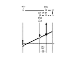
HV Loモードを設定した場合、および、HV Hiモードを設定した場合、ならびに直結モードを設定した場合には、エンジン5の上限回転数に基づいてエンジン5の上限出力が定まる。そのエンジン5の上限回転数は、例えば分割部9におけるピニオンギヤ13の許容回転数や、第1モータ6の駆動可能回転数などに基づいて定められている。図13にはピニオンギヤ13の許容回転数に基づいて定まる例を示しており、横軸に車速をとり、縦軸にエンジン5の上限回転数をとっている。図13にLoのラインで示すようにHV Loモードを設定した場合にピニオンギヤ13の許容回転数を制限値としてエンジン5を駆動すると、エンジン5の上限回転数は車速の増加に伴って緩やかに増大する。
When the HV Lo mode is set, when the HV Hi mode is set, and when the direct connection mode is set, the upper limit output of the
一方、図13にHiのラインで示すようにHV Hiモードを設定した場合にピニオンギヤ13の許容回転数を制限値としてエンジン5を駆動すると、HV Loモードを設定した場合にピニオンギヤ13の許容回転数を制限値としてエンジン5を駆動した場合よりも、エンジン5の上限回転数が高回転数になる。なお、そのエンジン5の上限回転数の増加率は、上述したHV Loモードを設定した場合のエンジン5の上限回転数とほぼ同じ、あるいは、やや小さくなる。
On the other hand, when the
そして、図13にFixのラインで示すように直結モードを設定した場合にピニオンギヤ13の許容回転数を制限値としてエンジン5を駆動すると、HV Loモードを設定した場合にピニオンギヤ13の許容回転数を制限値としてエンジン5を駆動した場合よりも、いずれの車速においても、エンジン5の上限回転数が低回転数になる。なお、そのエンジン5の上限回転数の増加率は、HV Loモードを設定した場合のピニオンギヤ13の許容回転数に基づいたエンジン5の上限回転数とほぼ同じである。
When the
上述したように直結モードは、出力側に動力を伝達する割合が、HV HiモードやHV Loモードの他のモード(以下、単に他のモードとも記す)よりも大きい。したがって、他のモードを設定した場合におけるエンジン5の上限出力が、直結モードを設定した場合におけるエンジン5の上限出力よりも小さいとしても、リングギヤ18に伝達される動力(またはトルク)が大きくなる。
As described above, in the direct coupling mode, the ratio of transmitting power to the output side is larger than that in other modes (hereinafter, also simply referred to as other modes) in the HV Hi mode and the HV Lo mode. Therefore, even if the upper limit output of the
具体的には、直結モードは、エンジンと第1モータと第2モータとによりトルクを出力する。つまり、直結モードを設定した場合における駆動力は、リングギヤ18から伝達されるトルク(エンジントルク)と第1モータ6および第2モータ7から出力されたトルクとの和に基づいた値になる。第1モータ6および第2モータ7の出力トルクは、蓄電装置47から各モータ6,7に充分な電力を出力できる場合には、各モータ6,7で最大トルクを出力することができる。したがって、そのような場合、車両の最大駆動力は、リングギヤ18から出力される動力(またはトルク)と第1モータ6および第2モータ7から出力された動力とに基づいた大きさになる。なお、上記のエンジントルクは、エンジン5の出力軸15の回転数を増大させる正トルク、および、出力軸15の回転数を低下させる負トルク(エンジン5を連れ回す)を含み、これら正トルクおよび負トルクが、この発明の実施形態における「エンジントルク」に相当する。また同様に、上記の各モータ6,7におけるトルクは、各モータ6,7の回転数を増大させる正トルク、および、各モータ6,7の回転数を低下させる負トルク(すなわち回生トルク)を含み、第2モータ7における最大トルクが、この発明の実施形態における「第2回転機からの最大トルク」に相当する。
Specifically, in the direct connection mode, torque is output by the engine, the first motor, and the second motor. That is, the driving force when the direct coupling mode is set is a value based on the sum of the torque (engine torque) transmitted from the
これに対して、HV LoモードやHV Hiモードを設定した場合における駆動力は、リングギヤ18から伝達されるトルクと第2モータ7から出力されたトルクとの和に基づいた値になる。そして、第1モータ6はエンジン回転数を上述した上限回転数(最大回転数)に制御し、またそのエンジン5の上限回転数を維持するように反力トルクを出力する。つまり他のモードを設定した場合には、第1モータ6の出力トルクは制限され、第1モータ6は最大トルクを出力できない場合がある。すなわち上述した直結モードを設定した場合には、第1モータ6は上記の反力トルクを出力することがないから、第1モータ6の出力トルクは制限されず、蓄電装置47から各モータ6,7に充分な電力を供給できる場合には、その制限された第1モータ6のトルクの分、直結モードの方が他のモードより大きなトルクを出力することができる。そのため、第1モータ6のトルクの差分、直結モードを設定した方が、他のモードを設定するよりも大きな最大駆動力を得ることができる。なお、ここで示す「最大駆動力」とは、構成部材の回転数の制限などを考慮して、出力できる駆動力の上限値を意味する。また、上記のHV LoモードやHV Hiモードにおいて、エンジン5を上限回転数で回転させている際のエンジントルクを、第1モータ6から反力トルクを出力することによりリングギヤ18に作用させ、かつ第2モータから最大トルクを出力する走行モードが、この発明の実施形態における「第1走行モード」に相当する。そして、上記の直結モードにおいて、第1モータ6およびエンジン5ならびに第2モータ7から最大トルクを出力する走行モードが、この発明の実施形態における「第2走行モード」に相当する。
On the other hand, when the HV Lo mode or the HV Hi mode is set, the driving force is a value based on the sum of the torque transmitted from the
一方、蓄電装置47の充電残量が少ない場合や蓄電装置47の温度が低温の場合、あるいは蓄電装置47の温度が上限温度近傍である場合などであって、蓄電装置47から各モータ6,7に充分な電力を供給できない場合、すなわち蓄電装置47から各モータ6,7に供給する電力が制限されている(出力可能電力が制限されている)場合には、上述した最大駆動力が低下する。例えば、直結モードでは、上述したように蓄電装置47から第1モータ6と第2モータ7とに電力を供給してトルクを出力しているから、その蓄電装置47から充分な電力を供給できない場合には、出力できる最大トルクが低下する。これに対して、他のモードでは、上述したように第1モータ6が、エンジン回転数を上限回転数に制御ならびにその上限回転数を維持するように出力が制限されているため、蓄電装置47から第2モータ7に供給する電力が制限されている場合であっても、その影響度は直結モードに比べて少ない。また、上述したように直結モードにおけるエンジン5の上限回転数は、他のモードの上限回転数より低いから、このように蓄電装置47から各モータ6,7に供給する電力が制限されている場合には、上述した第1モータ6のトルクの差分が低減し、その差分がエンジン5の出力トルクの差分(リングギヤ18から出力される動力の差)よりも小さいと、直結モードを設定した場合よりも他のモード(HV HiモードやHV Loモード)を設定した場合の方が大きな駆動力を得ることができる。なお、第1電力制御装置44や第2電力制御装置45の温度により蓄電装置47から出力できる電力が制限されている場合もあり、蓄電装置47自体や第1電力制御装置44、第2電力制御装置45などの状態を考慮して、蓄電装置47から各モータ6,7に供給可能な電力が定められ、その各モータ6,7に供給可能な電力が、この発明の実施形態における「上限電力」に相当する。
On the other hand, when the remaining charge amount of
図14から図16に、蓄電装置47の出力可能電力に応じた最大駆動力の変化を説明するための図を示している。図14から図16において、横軸は車速を示し、縦軸は最大駆動力を示している。また、Loモードのラインを実線で示し、Hiモードのラインを破線で示し、直結モードのラインを一点鎖線で示している。そして、図14は、蓄電装置47から充分な電力を出力した場合の最大駆動力を示し、図15は、蓄電装置47から図14より少ない電力(すなわち充分でない電力)を出力した場合の最大駆動力を示し、図16は、蓄電装置47から図15より更に少ない電力を出力した場合の最大駆動力を示している。
FIGS. 14 to 16 show diagrams for explaining the change of the maximum driving force according to the available output power of
図14から図16に示すように直結モードを設定した場合における最大駆動力と、他のモードを設定した場合における最大駆動力とは、蓄電装置47から出力される電力毎に異なる。具体的には、図14に示すように、蓄電装置47から充分に電力を出力することができる場合には、直結モードを設定した方が他のモードを設定した場合より最大駆動力が大きくなる。一方、図15および図16に示すように、蓄電装置47からの出力可能電力が低下してその蓄電装置47から充分に電力を出力することができない場合には、他のモードを設定した方が直結モードを設定した場合より最大駆動力が大きくなる。
As shown in FIGS. 14 to 16, the maximum driving force when the direct connection mode is set and the maximum driving force when the other mode is set are different for each power output from the
そのため、この発明の実施形態における駆動力制御装置は、蓄電装置47から各モータ6,7に供給できる電力が低下することに伴う最大駆動力の低下を抑制できるように構成されている。その制御の一例を図17に示している。図17に示す制御例では、まず、車速Vが第1所定車速Vs1よりも高車速か否かを判断する(ステップS1)。このステップS1における第1所定車速Vs1は、低車速の場合における駆動力は、パワーの低下に伴う感度が低く、所定の車速以上でこの制御を実行するため、第1所定車速Vs1はその所定車速に相当するものである。したがって、このステップS1で否定的に判断された場合、すなわち車速Vが第1所定値Vs1より低車速の場合には、これ以降の制御を実行することなくリターンする。
Therefore, the driving force control device in the embodiment of the present invention is configured to be able to suppress the decrease in the maximum driving force accompanying the decrease in the power that can be supplied from the
一方、このステップS1で肯定的に判断された場合、すなわち車速Vが第1所定値Vs1より高車速の場合には、蓄電装置47から各モータ6,7に供給できる電力が、他のモードを設定した場合よりも駆動力が低下する程度まで低下しているか否かを判断する(ステップS2)。蓄電装置47から各モータ6,7に供給できる電力は、蓄電装置47の出力可能電力や、第1電力制御装置44、第2電力制御装置45の耐久性の低下を抑制するための制限電力などに基づいて定めることができる。また、蓄電装置47の出力可能電力は、蓄電装置47の充電残量や蓄電装置47の温度に応じて定められている。ここに示す例では、上記の判断をする一例として、蓄電装置47の出力可能電力が、閾値αよりも少ないか否かを判断している(出力可能電力<α)。なお、閾値αは、実験やシミュレーションなどに基づいて予め定めることができる。そして、この閾値αが、この発明の実施形態における「第1閾値」に相当する。
On the other hand, if a positive determination is made in step S1, that is, if the vehicle speed V is higher than the first predetermined value Vs1, the power that can be supplied from the
閾値αは、例えば、直結モードを設定している場合に、蓄電装置47から供給される電力により第1モータ6と第2モータ7とが定格トルクを出力することができること、および、他のモードを設定している場合にリングギヤ18に伝達されるトルクから直結モードを設定している場合にリングギヤ18に伝達されるトルクを減算した値が、各モータ6,7の定格トルクから、他のモードを設定している場合における第2モータ7の出力トルクを減算した値(すなわち第1モータ6のトルク分)よりも大きくなることとの二つの条件を満たす蓄電装置47の出力電力に定めることができる。すなわち、直結モードを設定することにより、リングギヤ18に伝達されるトルク差以上に、各モータ6,7の出力トルクの低下量が大きくなる電力量を閾値αとして定めることができる。
The threshold value α is, for example, that the first motor 6 and the
または、蓄電装置47の出力可能電力毎に、直結モードを設定した場合の最大駆動力と、他のモードを設定した場合の最大駆動力とを予め演算や実験などに基づいて求めておき、直結モードを設定した場合の最大駆動力が、他のモードを設定した場合の最大駆動力以下となる蓄電装置47の出力可能電力を、閾値αとして求めてもよい。なお、この出力可能電力が閾値αより小さい場合は、既述した図でいうと図15および図16に相当し、つまり、直結モードでは、最大駆動力を出力できない。
Alternatively, for each possible output power of
したがって、このステップS2で否定的に判断された場合、すなわち蓄電装置47の出力可能電力が、閾値αよりも大きい場合には、これ以降の制御を実行することなくリターンする。これとは反対に、このステップS2で肯定的に判断された場合、すなわち蓄電装置47の出力可能電力が、閾値αよりも少ない場合は、直結モードを設定することを制限する(ステップS3)。なお、このステップS3における制限とは、蓄電装置47からの出力可能電力が閾値αよりも小さい場合に、一律に直結モードを設定することを禁止するものではないことを意味している。例えば、図11や図12に示すマップに基づいて走行モードを設定する場合において、HV HiモードやHV Loモードから直結モードに切り替える条件が成立した場合であっても、所定時間が経過するまで現在設定されている走行モード(HV HiモードまたはHV Loモード)を維持するなどとしてもよい。または、他のモードから直結モードに切り替えたとしても要求駆動力を充足することができる場合には、その直結モードを設定することとしてもよい。あるいは、現状、直結モードが設定され、そのまま直結モードで要求駆動力を充足することができる場合には、他のモードから直結モードに切り替えなくてもよい。なお、これ以降の説明では、ステップS3では、直結モードが制限されて他のモードが設定されたものとして説明する。
Therefore, if a negative determination is made in step S2, that is, if the available output power of the
ついで、上述したステップS2で判断した蓄電装置47の出力可能電力が、更に閾値βより小さいか否か(出力可能電力<β)を判断する(ステップS4)。これは、上述したステップS3で直結モードが制限されているから、他のモード、すなわちHV LoモードもしくはHV Hiモードが設定されている。蓄電装置47から第2モータ7に充分電力を供給できる通常の場合であれば、HV LoモードとHV Hiモードとでは、HV Loモードの方が最大駆動力は大きい。したがって、このステップS4では、蓄電装置47から供給できる電力が減少することにより、HV LoモードとHV Hiモードとの関係が逆転して、すなわちHV Hiモードの方がHV Loモードより最大駆動力を出力できるか否かを判断する。言い換えれば更にHV Loモードを制限すべきか否かを判断する。なお、この閾値βは、上述した閾値αよりも小さい値に定められており、その閾値βは閾値αと同様に定めることができる。簡潔に説明すると、HV LoモードとHV Hiモードとの関係で、HV Loモードを設定することにより、リングギヤ18に伝達されるトルク差以上に、第2モータ7の出力トルクの低下量が大きくなる電力量を閾値βとして定めることができる。または、蓄電装置47の出力可能電力毎に、HV Loモードを設定した場合の最大駆動力と、HV Hiモードを設定した場合の最大駆動力とを予め演算や実験などに基づいて求めておき、HV Loモードを設定した場合の最大駆動力が、HV Hiモードを設定した場合の最大駆動力以下となる蓄電装置47の出力可能電力を、閾値βとして求めてもよい。なお、この出力可能電力が閾値βより小さい場合は、既述した図でいうと図16に相当し、つまり、直結モードおよびHV Loモードでは、最大駆動力を出力できない。
Next, it is determined whether the available output power of the
したがって、このステップS4で肯定的に判断された場合、すなわち蓄電装置47の出力可能電力が、閾値βよりも小さい場合には、直結モードに加えて、更にHV Loモードを設定することを制限する(ステップS5)。なお、このステップS5における制限とは、蓄電装置47からの出力可能電力が閾値βよりも小さい場合に、一律に更にHV Loモードを設定することを禁止するものではないことを意味している。例えば、図11や図12に示すマップに基づいて走行モードを設定する場合において、HV Loモードに切り替えたとしても要求駆動力を充足することができる場合には、そのHV Loモードを設定することとしてもよい。あるいは、現状、HV Loモードが設定され、そのままHV Loモードで要求駆動力を充足することができる場合には、そのHV Loモードの状態を維持してもよい。一方、このステップS4で否定的に判断された場合、すなわち蓄電装置47の出力可能電力が、閾値βよりも大きい場合には、ステップS3の状態を維持したまま、つまり直結モードを設定することを制限したままリターンする。
Therefore, in the case of a positive determination in step S4, that is, when the available output power of
つぎに、この発明の実施形態における他の例について説明する。上述した図17に示す制御例では、蓄電装置47の出力可能電力を閾値αや閾値βより小さいか否かを判断することにより、直結モードを設定することを制限し、あるいは、直結モードおよびHV Loモードを設定することを制限し、それによりその制限された以外の走行モードを設定することで最大駆動力が過度に低下することを抑制することができる。一方、そのような制限を過度に実行すると、その制限された以外の走行モードでは運転者が要求する駆動力を得られない可能性がある。そのため、蓄電装置47から出力可能電力をより詳細に把握することにより最大駆動力の低下量を抑制することが好ましい。そこで、この発明の実施形態では、蓄電装置47から出力可能電力をより詳細に把握して、その状況において制限した直結モードやHV Loモードの設定することの制限を解除するように構成されている。
Next, another example of the embodiment of the present invention will be described. In the control example shown in FIG. 17 described above, setting of the direct connection mode is restricted by determining whether or not the available output power of
図18は、所定の条件の場合にHV Loモードを設定することの制限を解除する例を示したフローチャートであって、先ずHV Loモードを設定することを制限中か否かを判断する(ステップS10)。このステップS10は、上述した図17の制御例のステップS5で肯定的に判断されて蓄電装置47の出力可能電力が閾値βより小さい場合の状態であるか否かを判断するものである。したがって、このステップS10で否定的に判断された場合、すなわちHV Loモードの設定中でないと判断された場合にはこれ以降の制御を実行することなくリターンする。これとは反対に、このステップS10で肯定的に判断された場合には、ついで車速が第2所定車速Vs2より低車速か否かを判断する(ステップS20)。
FIG. 18 is a flow chart showing an example of releasing the restriction of setting the HV Lo mode under a predetermined condition, and it is first determined whether setting of the HV Lo mode is being restricted (step S10). This step S10 is to determine whether or not it is determined that the outputtable power of the
この第2所定車速Vs2は、図17の制御例で説明した第1所定車速Vs1と同様であって、低車速の場合における駆動力は、パワーの低下に伴う感度が低く、所定の車速以上でこの制御を実行するための所定値に相当するものである。したがって、このステップS20で肯定的に判断された場合、すなわち車速が第2所定車速Vs2より低車速である場合には、HV Loモードを設定することの制限を解除する(ステップS30)。なお、この第2所定車速は、第1所定車速より小さい値である(Vs1>Vs2)。 The second predetermined vehicle speed Vs2 is the same as the first predetermined vehicle speed Vs1 described in the control example of FIG. 17, and the driving force in the case of low vehicle speed has low sensitivity due to the decrease in power and is higher than the predetermined vehicle speed. It corresponds to a predetermined value for executing this control. Therefore, when the determination in step S20 is affirmative, that is, when the vehicle speed is lower than the second predetermined vehicle speed Vs2, the restriction of setting the HV Lo mode is released (step S30). The second predetermined vehicle speed is a value smaller than the first predetermined vehicle speed (Vs1> Vs2).
一方、上述したステップS20で否定的に判断された場合、すなわち車速が第2所定車速Vs2より低車速でないと判断された場合には、蓄電装置47の出力可能電力が閾値γより大きいか否かを判断する(ステップS40)。これは、HV Loモードの設定の制限の解除を蓄電装置47の出力可能電力に基づいて判断するものであって、つまりHV Loモードを設定した方が最大駆動力を発生させることができるか否かを判断する。したがって、この閾値γは、上述した閾値βより少なくとも大きい(β<γ)。このステップS40で肯定的に判断された場合、すなわち蓄電装置47の出力可能電力が閾値γより大きい場合には、HV Loモードを設定することの制限を解除する(ステップS30)。一方、このステップS40で否定的に判断された場合、すなわち蓄電装置47の出力可能電力が閾値γより小さい場合には、リターンする。つまり、HV Loモードを設定することの制限を維持する。
On the other hand, if negative determination is made in step S20 described above, that is, if it is determined that the vehicle speed is not lower than the second predetermined vehicle speed Vs2, whether the available output power of
図19は、所定の条件の場合に直結モードを設定することの制限を解除する例を示したフローチャートであって、先ず直結モードの設定することを制限中か否かを判断する(ステップS100)。このステップS100は、上述した図17の制御例におけるステップS2で肯定的に判断されて蓄電装置47の出力可能電力が閾値αより小さい場合の状態であるか否かを判断するものである。したがって、このステップS100で否定的に判断された場合、すなわち直結モードを設定中でないと判断された場合にはこれ以降の制御を実行することなくリターンする。これとは反対に、このステップS100で肯定的に判断された場合には、ついで車速が第2所定車速Vs2より低車速か否かを判断する(ステップS200)。
FIG. 19 is a flowchart showing an example of releasing the restriction on setting of the direct coupling mode in the case of a predetermined condition, and it is first determined whether setting of the direct coupling mode is being restricted (step S100) . This step S100 is to determine whether or not it is determined that the outputtable power of the
この第2所定車速Vs2は、図18の制御例で説明した第2所定車速Vs2と同様であって、低車速の場合における駆動力は、パワーの低下に伴う感度が低く、所定の車速以上でこの制御を実行するための所定値に相当するものである。したがって、このステップS200で肯定的に判断された場合、すなわち車速が第2所定車速Vs2より低車速である場合には、直結モードを設定することの制限を解除する(ステップS300)。 The second predetermined vehicle speed Vs2 is the same as the second predetermined vehicle speed Vs2 described in the control example of FIG. 18, and the driving force in the case of low vehicle speed has low sensitivity with the reduction of power and is higher than the predetermined vehicle speed. It corresponds to a predetermined value for executing this control. Therefore, if the determination in step S200 is affirmative, that is, if the vehicle speed is lower than the second predetermined vehicle speed Vs2, the restriction on setting the direct connection mode is released (step S300).
一方、上述したステップS200で否定的に判断された場合、すなわち車速が第2所定車速Vs2より低車速でないと判断された場合には、蓄電装置47の出力可能電力が閾値δより大きいか否かを判断する(ステップS400)。これは、直結モードを設定することの制限の解除を蓄電装置47の出力可能電力に基づいて判断するものであって、つまり他のモードを設定した方が最大駆動力を発生させることができるか否かを判断する。したがって、この閾値δは、上述した閾値αより大きい(α<δ)。このステップS400で肯定的に判断された場合、すなわち蓄電装置47の出力可能電力が閾値δより大きい場合には、直結モードの設定することの制限を解除する(ステップS300)。一方、このステップS400で否定的に判断された場合、すなわち蓄電装置47の出力可能電力が閾値δより小さい場合には、リターンする。つまり、直結モードを設定することの制限を維持する。
On the other hand, if negative determination is made in step S200 described above, that is, if it is determined that the vehicle speed is not lower than the second predetermined vehicle speed Vs2, whether the available output power of
つぎに、停車時から所定車速まで加速した後に減速した場合における、蓄電装置47の出力可能電力(Wout)の変化と、直結モードを設定することの制限の有無と、HV Loモードを設定することの制限の有無とを、図20に示すタイムチャートを参照して説明する。なお、図20には、その車速の変化、蓄電装置47から出力可能な電力の変化、直結モードを設定することの制限の有無、HV Loモードを設定することの制限の有無に加えて蓄電装置47の充電残量(SOC)の変化を示している。
Next, change the possible output power (Wout) of the
図20に示す例では、t0時点で走行し始め、t3時点で所定車速に到達し、その後、減速している。したがって、車速は、t0時点からt3時点に向けて次第に増大し、t3時点以降では、次第に低下している。また、蓄電装置47の電力を走行のために使用していることにより、t0時点から蓄電装置47の充電残量が次第に低下し、所定車速到達後は、要求駆動力が低下することに伴って蓄電装置47の充電残量が緩やかに増加する。また、蓄電装置47の出力可能電力(最大出力可能電力)は、蓄電装置47の充電残量と蓄電装置47の温度(図示せず)とに基づいて定まるため、図20に示す例では、t0時点からt3時点までの間は、例えばその蓄電装置47の温度上昇などを理由として、蓄電装置47の最大出力が減少し、その後、t5時点までの間は、蓄電装置47の充電残量の増加に伴って、蓄電装置47の出力可能電力は増大されている。
In the example shown in FIG. 20, the vehicle starts traveling at time t0, reaches a predetermined vehicle speed at time t3, and then decelerates. Therefore, the vehicle speed gradually increases from time t0 to time t3, and gradually decreases after time t3. Also, by using the power of
このような場合において、t1時点で、第1所定車速Vs1よりも高車速になるとともに、その際における蓄電装置47の出力可能電力が閾値α未満であることにより、上記ステップS1およびステップS2で肯定的に判断されるため、直結モードを設定することが制限される。
In such a case, the vehicle speed becomes higher than the first predetermined vehicle speed Vs1 at time t1, and the outputable power of the
t2時点では、蓄電装置47の出力可能電力が閾値βよりも小さくなることにより、上記ステップS4で肯定的に判断されるため、直結モードの設定の制限に加えて、HV Loモードを設定することが制限される。ついで、t4時点では、蓄電装置47の出力可能電力が閾値βより大きくなり、更に閾値γよりも大きくなることにより、上述したステップS40で肯定的に判断されるため、HV Loモードを設定することの制限が解除される。なお、この場合であっても直結モードを設定することの制限は維持されたままである。そして、t5時点では、蓄電装置47の出力可能電力が更に大きくなり、閾値δよりも大きくなることにより、上記のステップS400で肯定的に判断されるため、直結モードを設定することの制限が解除される。
At time t2, since the outputable power of
上述したように、他のモードを設定した場合の最大駆動力の方が、直結モードを設定した場合の最大駆動力よりも大きくなる程度まで、蓄電装置47の出力可能電力が低下した場合には、直結モードの設定を制限することにより、蓄電装置47の出力可能電力に基づいた駆動力の低下量を低減すること、ならびに、駆動力が不足することを抑制することができる。また、他のモードにおいても、すなわちHV LoモードとHV Hiモードとの関係においても同様であり、つまりHV Loモードを設定した場合よりもHV Hiモードを設定した場合の方が最大駆動力が大きくなる程度まで、蓄電装置47の出力可能電力が低下した場合には、HV Loモードを設定することを制限することにより、蓄電装置47の出力可能電力に基づいた駆動力の低下量を低減すること、ならびに、駆動力が不足することを抑制することができる。
As described above, when the available output power of
また、低車速域(第1所定車速Vs1や第2所定車速Vs2以下の車速)や各蓄電装置47の出力可能電力の閾値α、閾値β、閾値γ、および閾値δの各閾値に基づいて、直結モードやHV Loモードの設定を制限し、あるいは、その制限を解除することにより、車速や蓄電装置47の出力可能な電力に応じて、最適な走行モードの選択が可能となる。さらに、そのような最適な走行モードを選択できるから、車両における最大駆動力を適宜発生させることができる。つまり、蓄電装置から各モータ6,7に供給可能な電力が低下することで、最大駆動力が低下した場合であっても、その際に最適な走行モードの設定が可能となり、その結果、最大駆動力の低下量を低減することができる。
Also, based on the low vehicle speed range (the vehicle speed below the first predetermined vehicle speed Vs1 or the second predetermined vehicle speed Vs2) and the threshold α, threshold β, threshold γ, and threshold δ of the available output power of each
なお、この発明の複数の実施形態について説明したが、この発明は上述した例に限定されないのであって、この発明の目的を達成する範囲で適宜変更してもよい。上述した各実施形態では、いずれも最大駆動力の低下量を抑制するように構成された例を示したものの、この制御例は、負の駆動力、すなわち蓄電装置47の入力可能電力が制限されて最大制動力が低下する場合に適用してもよい。そのような場合、上述した例において、出力可能電力を入力可能電力に読み替える。つまり、蓄電装置47の入力可能電力に応じて、直結モードの設定を制限、もしくは、直結モードおよびHV Loモードの設定を制限するように構成してよい。図21から図23に、蓄電装置47の入力可能電力に応じた最大制動力の変化を説明するための図を示している。図21から図23において、横軸は車速を示し、縦軸は最大制動力を示している。また、Loモードのラインを実線で示し、Hiモードのラインを破線で示し、直結モードのラインを一点鎖線で示している。そして、図21は、蓄電装置47に充分な電力を入力した場合の最大制動力を示し、図22は図21より少ない電力を入力した場合の最大制動力を示し、図23は図22より更に少ない電力を入力した場合の最大制動力を示している。
In addition, although several embodiment of this invention was described, this invention is not limited to the example mentioned above, Comprising: You may change suitably in the range which achieves the objective of this invention. In each of the above-described embodiments, although an example is shown in which all are configured to suppress the reduction amount of the maximum driving force, in this control example, the negative driving force, that is, the input available power of the
図21から図23に示すように直結モードを設定した場合における最大制動力と、他のモードを設定した場合における最大制動力とは、蓄電装置47に入力される電力毎に異なる。具体的には、図21に示すように、蓄電装置47に充分な電力を入力することができる場合には、直結モードを設定した方が他のモードを設定した場合より最大制動力が大きくなる。一方、図22および図23に示すように、蓄電装置47への入力可能電力が低下してその蓄電装置47に充分な電力を入力することができない場合、すなわち蓄電装置47の充電残量が多い場合や蓄電装置47の温度が低温の場合、あるいは蓄電装置47の温度が上限温度近傍である場合などであって、蓄電装置47に入力される電力が制限されている場合には、他のモードを設定した方が直結モードを設定した場合より最大制動力が大きくなる。
As shown in FIGS. 21 to 23, the maximum braking force when the direct connection mode is set and the maximum braking force when the other mode is set are different for each power input to the
したがって、そのような場合、上述した図17の制御を実行し、つまり蓄電残量47への入力可能電力が、閾値α、閾値βに応じて直結モードの設定を制限、あるいは、直結モードとHV Loモードとの設定を制限し、車両における最大制動力の低下量を抑制することができる。また、図18および図19の制御例で示したように、蓄電残量47への入力可能電力が、閾値γ、閾値δに応じてHV Loモードを設定の制限を解除すること、ならびに、直結モードを設定の制限を解除することにより、より詳細なレンジで最大制動力の低下量を抑制することができる。なお、図17および図18ならびに図19においても、出力可能電力を入力可能電力に読み替える。したがって、入力可能電力に読み替えた閾値αが、この発明の実施形態における「第2閾値」に相当する。
Therefore, in such a case, the control of FIG. 17 described above is executed, that is, the possible input power to storage
1R,1L…前輪、 2…第1駆動装置、 5…エンジン、 6…第1モータ(第1回転機)、 7…第2モータ(第2回転機)、 8…動力分割機構(伝動機構)、 9…分割部、 10…変速部、 11,17,32…サンギヤ、 12,18,26,33,42…リングギヤ、 13,19,34…ピニオンギヤ、 14,20,35…キャリヤ、 30…リアモータ、 47…蓄電装置、 48…ECU。
DESCRIPTION OF
Claims (1)
発電機能および電動機能を有する第1回転機と、
前記エンジンが連結された第1回転要素と、前記第1回転機が連結された第2回転要素と、駆動輪にトルク伝達可能に連結された第3回転要素とを有する伝動機構と、
前記第3回転要素の出力側の部材にトルクを伝達可能に連結された発電機能および電動機能を有する第2回転機と、
蓄電装置とを備え、
前記第1回転機と前記第2回転機とが電気的に接続されるとともに、前記蓄電装置と前記第1回転機および前記第2回転機とが電気的に接続され、
前記エンジンを上限回転数で回転させている際のエンジントルクを、前記第1回転機から反力トルクを出力することにより前記駆動輪に作用させ、かつ前記第2回転機から最大トルクを出力する第1走行モードと、
前記第1回転要素と前記第2回転要素と前記第3回転要素とを一体に回転させつつ、前記エンジンおよび前記第1回転機ならびに前記第2回転機から最大トルクを出力する第2走行モードとを設定可能に構成されたハイブリッド車両の駆動力制御装置において、
前記蓄電装置に入力される電力が第1閾値未満に制限されている場合、あるいは前記蓄電装置から出力される電力が第2閾値未満に制限されている場合には、前記第2走行モードの設定を制限するように構成されている
ことを特徴とするハイブリッド車両の駆動力制御装置。 With the engine,
A first rotating machine having a power generation function and an electric function;
A transmission mechanism having a first rotating element to which the engine is connected, a second rotating element to which the first rotating machine is connected, and a third rotating element to which torque transmission can be transmitted to a drive wheel;
A second rotating machine having a power generation function and an electric function connected so as to be able to transmit torque to a member on the output side of the third rotating element;
Power storage device,
The first rotating machine and the second rotating machine are electrically connected, and the power storage device is electrically connected to the first rotating machine and the second rotating machine.
The engine torque during rotation of the engine at the upper limit rotational speed is caused to act on the drive wheel by outputting a reaction torque from the first rotating machine, and the maximum torque is output from the second rotating machine The first driving mode,
A second traveling mode in which maximum torque is output from the engine, the first rotating machine, and the second rotating machine while integrally rotating the first rotating element, the second rotating element, and the third rotating element; In a driving force control device of a hybrid vehicle configured to be able to set
When the power input to the storage device is limited to less than a first threshold, or when the power output from the storage device is limited to less than a second threshold, setting of the second travel mode A driving force control device for a hybrid vehicle, wherein the driving force control device is configured to limit.
Priority Applications (1)
| Application Number | Priority Date | Filing Date | Title |
|---|---|---|---|
| JP2017200812A JP2019073173A (en) | 2017-10-17 | 2017-10-17 | Hybrid-vehicular drive force control apparatus |
Applications Claiming Priority (1)
| Application Number | Priority Date | Filing Date | Title |
|---|---|---|---|
| JP2017200812A JP2019073173A (en) | 2017-10-17 | 2017-10-17 | Hybrid-vehicular drive force control apparatus |
Publications (1)
| Publication Number | Publication Date |
|---|---|
| JP2019073173A true JP2019073173A (en) | 2019-05-16 |
Family
ID=66542962
Family Applications (1)
| Application Number | Title | Priority Date | Filing Date |
|---|---|---|---|
| JP2017200812A Pending JP2019073173A (en) | 2017-10-17 | 2017-10-17 | Hybrid-vehicular drive force control apparatus |
Country Status (1)
| Country | Link |
|---|---|
| JP (1) | JP2019073173A (en) |
Cited By (2)
| Publication number | Priority date | Publication date | Assignee | Title |
|---|---|---|---|---|
| CN112238853A (en) * | 2019-07-18 | 2021-01-19 | 丰田自动车株式会社 | Vehicle control device |
| CN113550834A (en) * | 2020-04-03 | 2021-10-26 | 丰田自动车株式会社 | Control device for hybrid vehicle |
-
2017
- 2017-10-17 JP JP2017200812A patent/JP2019073173A/en active Pending
Cited By (4)
| Publication number | Priority date | Publication date | Assignee | Title |
|---|---|---|---|---|
| CN112238853A (en) * | 2019-07-18 | 2021-01-19 | 丰田自动车株式会社 | Vehicle control device |
| CN112238853B (en) * | 2019-07-18 | 2023-09-08 | 丰田自动车株式会社 | vehicle controls |
| CN113550834A (en) * | 2020-04-03 | 2021-10-26 | 丰田自动车株式会社 | Control device for hybrid vehicle |
| CN113550834B (en) * | 2020-04-03 | 2023-10-03 | 丰田自动车株式会社 | Hybrid vehicle control devices |
Similar Documents
| Publication | Publication Date | Title |
|---|---|---|
| CN109941269B (en) | Drive force control device for hybrid vehicle | |
| JP5915744B2 (en) | Control device for hybrid vehicle | |
| JP5991375B2 (en) | Control device for hybrid vehicle | |
| JP6024691B2 (en) | Control device for drive device for hybrid vehicle | |
| CN109720333B (en) | Control device for hybrid vehicle | |
| KR102075890B1 (en) | Vehicle, and method of controlling vehicle | |
| CN109774698B (en) | Drive force control device for hybrid vehicle | |
| JP7120035B2 (en) | Vehicle transmission control device | |
| CN109383267B (en) | Driving force control device for hybrid vehicle | |
| JP5907155B2 (en) | Control device for hybrid drive | |
| CN110920599B (en) | Control device for hybrid vehicle | |
| JP6052396B2 (en) | Hybrid vehicle drive device | |
| JP2019108056A (en) | Driving force control device of vehicle | |
| JP2019073173A (en) | Hybrid-vehicular drive force control apparatus | |
| CN110329240B (en) | vehicle controls | |
| JP6965799B2 (en) | Hybrid vehicle control device | |
| JP2020097334A (en) | Control device of hybrid vehicle | |
| JP4877212B2 (en) | Control device for hybrid vehicle | |
| JP7172894B2 (en) | vehicle controller | |
| JP7215967B2 (en) | Hybrid vehicle control device | |
| JP6897519B2 (en) | Transmission controller | |
| JP7091981B2 (en) | Hybrid vehicle control device | |
| CN114194174A (en) | Control device for hybrid vehicle | |
| JP5071273B2 (en) | Vehicle and control method thereof | |
| JP7081439B2 (en) | Hybrid vehicle control device |