JP2018112410A - Electronic component life prediction apparatus and electronic component life prediction method - Google Patents
Electronic component life prediction apparatus and electronic component life prediction method Download PDFInfo
- Publication number
- JP2018112410A JP2018112410A JP2017001178A JP2017001178A JP2018112410A JP 2018112410 A JP2018112410 A JP 2018112410A JP 2017001178 A JP2017001178 A JP 2017001178A JP 2017001178 A JP2017001178 A JP 2017001178A JP 2018112410 A JP2018112410 A JP 2018112410A
- Authority
- JP
- Japan
- Prior art keywords
- variation
- electronic components
- lifetime
- electronic component
- test
- Prior art date
- Legal status (The legal status is an assumption and is not a legal conclusion. Google has not performed a legal analysis and makes no representation as to the accuracy of the status listed.)
- Granted
Links
Images


Landscapes
- Led Devices (AREA)
- Testing Of Individual Semiconductor Devices (AREA)
- Testing Electric Properties And Detecting Electric Faults (AREA)
- Fixed Capacitors And Capacitor Manufacturing Machines (AREA)
Abstract
【課題】電子部品の寿命を短時間で予測する。【解決手段】実施の形態に係る電子部品の寿命予測装置は、記憶部、ばらつき取得部及び寿命算出部を備えている。記憶部は、複数の負荷因子を同時に与える複合負荷試験を実施した後の複数の第1の電子部品における特性の変動量のばらつきと前記複数の第1の電子部品の寿命との相関関係を記憶する。ばらつき取得部は、複合負荷試験を実施した後の複数の第2の電子部品における特性の変動量のばらつきを取得する。寿命算出部は、記憶部に記憶された相関関係と前記取得された特性の変動量のばらつきとに基づいて、複数の第2の電子部品の寿命を算出する。【選択図】図1The life of an electronic component is predicted in a short time. An electronic component lifetime prediction apparatus according to an embodiment includes a storage unit, a variation acquisition unit, and a lifetime calculation unit. The storage unit stores a correlation between a variation in characteristic variation in the plurality of first electronic components and a lifetime of the plurality of first electronic components after performing a composite load test that simultaneously applies a plurality of load factors. To do. The variation acquisition unit acquires the variation in the variation amount of the characteristics in the plurality of second electronic components after the combined load test is performed. The lifetime calculation unit calculates the lifetimes of the plurality of second electronic components based on the correlation stored in the storage unit and the obtained variation in the variation amount of the characteristic. [Selection] Figure 1
Description
本発明の実施形態は、電子部品の寿命予測装置及び電子部品の寿命予測方法に関する。 Embodiments described herein relate generally to an electronic component lifetime prediction apparatus and an electronic component lifetime prediction method.
電解コンデンサやLEDなどの電子部品は、静電容量などの諸特性が経時的に劣化することが知られている。そこで、電子部品の寿命(耐用期間)を短時間で予測する技術が提案されている。 It is known that various characteristics such as capacitance of electronic parts such as electrolytic capacitors and LEDs deteriorate over time. Therefore, a technique for predicting the lifetime (lifetime) of an electronic component in a short time has been proposed.
電子部品の寿命を予測する場合、例えば加速劣化試験を電子部品に対して実施することにより、耐用年数などが検証される。一般に、電子部品の保障期間や規格を考慮したうえで加速劣化試験を行う際には、電子部品の実使用環境下における耐用期間を予測することが重要となる。 When predicting the lifetime of an electronic component, the service life and the like are verified by performing an accelerated deterioration test on the electronic component, for example. In general, when an accelerated deterioration test is performed in consideration of the warranty period and standards of an electronic component, it is important to predict the lifetime of the electronic component in an actual usage environment.
近年では、電子部品の長寿命化(耐用期間の長期化)に伴い、数千時間から数万時間にも及ぶ加速劣化試験を行う必要性がある。このため、近年の電子部品は、耐用期間の予測に多くの時間を要する。つまり、電子部品を搭載する電子機器類の開発期間を短縮するためにも、電子部品の寿命の予測に要する時間を削減することが求められている。 In recent years, it is necessary to perform accelerated deterioration tests ranging from several thousand hours to several tens of thousands of hours as the life of electronic components is extended (longer service life). For this reason, in recent electronic parts, it takes much time to predict the service life. That is, in order to shorten the development period of electronic devices on which electronic components are mounted, it is required to reduce the time required for predicting the lifetime of electronic components.
そこで、本発明が解決しようとする課題は、電子部品の寿命を短時間で予測できる電子部品の寿命予測装置及び電子部品の寿命予測方法を提供することである。 Therefore, the problem to be solved by the present invention is to provide an electronic component lifetime predicting apparatus and an electronic component lifetime predicting method capable of predicting the lifetime of an electronic component in a short time.
実施の形態に係る電子部品の寿命予測装置は、記憶部、ばらつき取得部及び寿命算出部を備えている。記憶部は、複数の負荷因子を同時に与える複合負荷試験を実施した後の複数の第1の電子部品における特性の変動量のばらつきと前記複数の第1の電子部品の寿命との相関関係を記憶する。ばらつき取得部は、複合負荷試験を実施した後の複数の第2の電子部品における特性の変動量のばらつきを取得する。寿命算出部は、記憶部に記憶された相関関係と前記取得された特性の変動量のばらつきとに基づいて、複数の第2の電子部品の寿命を算出する。 An electronic component lifetime prediction apparatus according to an embodiment includes a storage unit, a variation acquisition unit, and a lifetime calculation unit. The storage unit stores a correlation between a variation in characteristic variation in the plurality of first electronic components and a lifetime of the plurality of first electronic components after performing a composite load test that simultaneously applies a plurality of load factors. To do. The variation acquisition unit acquires the variation in the variation amount of the characteristics in the plurality of second electronic components after the combined load test is performed. The lifetime calculation unit calculates the lifetimes of the plurality of second electronic components based on the correlation stored in the storage unit and the obtained variation in the variation amount of the characteristic.
本発明によれば、電子部品の寿命を短時間で予測することが可能な電子部品の寿命予測装置及び電子部品の寿命予測方法を提供することができる。 ADVANTAGE OF THE INVENTION According to this invention, the lifetime prediction apparatus of an electronic component and the lifetime prediction method of an electronic component which can estimate the lifetime of an electronic component in a short time can be provided.
以下、実施の形態を図面に基づき説明する。
図1に示すように、本実施形態に係る電子部品の寿命予測装置10は、相関関係記憶部11、ばらつき取得部12、寿命算出部13、データベース14、影響度判定部15などを備えている。
Hereinafter, embodiments will be described with reference to the drawings.
As shown in FIG. 1, the electronic component
相関関係記憶部11は、複合負荷試験を実施した後の複数の第1の電子部品における特性の変動量のばらつき(機能余裕度SN比)と、前記複数の第1の電子部品の寿命との相関関係(相関近似線)を記憶する。複合負荷試験は、試験対象の電子部品に対して複数の負荷因子を同時に与える。一方、ばらつき取得部12は、前記複合負荷試験を実施した後の複数の第2の電子部品における特性の変動量のばらつきを取得する。ここで、上記した複数の第1及び第2の電子部品のそれぞれは、製品の仕様が互いに共通する電子部品であって、より具体的には、製造メーカや製造場所などが異なるものの、製品のスペック(製品規格)が同じ電子部品である。
The
寿命算出部13は、相関関係記憶部11に記憶された相関関係と、ばらつき取得部12によって取得された特性の変動量のばらつきと、に基づいて、前記複数の第2の電子部品の寿命を算出する。データベース14は、電子部品の寿命の予測に必要な各種のデータを記憶している。影響度判定部15は、複合負荷試験に適用する負荷因子を選定するために、前記第1、第2の電子部品の経時的劣化に対する単一の負荷因子(負荷因子毎)の影響度を判定する。なお、相関関係記憶部11、ばらつき取得部12、寿命算出部13などの図1に示す各部の構成については後に詳述する。
The
図2に示すように、本実施形態では、寿命の予測に適用される第1、第2の電子部品としてリードタイプの電解コンデンサ20を例示する。電解コンデンサ20は、電源回路の平滑用として、産業機器に多用されている有限寿命部品である。電解コンデンサ20は、スリーブ21、アルミニウムケース22、素子部23、封口ゴム24、アルミニウムリード25、リード線26を有する。なお、電解コンデンサが表面実装型の場合、リード線が図2に示すものとは異なる形状となる。
As shown in FIG. 2, in the present embodiment, a lead-type
図2に示すように、素子部23は、アルミ箔の表面をエッチング処理することによって表面積を拡大し、耐電圧が高くて薄い酸化被膜を化成処理で形成した陽極箔と、エッチング処理のみの陰極箔との間に電解紙を挿入して、円筒形の素子に巻き取ることによって製造される。さらに、素子部23に電解液を含浸させ、素子部23をアルミニウムケース22に入れた後、封口ゴム24でパッキングし、アルミニウムケース22に絞り加工を施すことで封止を行う。この後、定格値など必要な表示を施したスリーブ21をアルミニウムケース22の外側に被覆する。
As shown in FIG. 2, the
このような構造の電解コンデンサ20は、経時的な劣化によって、内部に含浸された電解液が封口ゴム24の周辺から外部へ流れ出し、静電容量、誘電体内での電気エネルギ損失の度合いを表す誘電正接(tanδ)、漏れ電流、といった各種の特性が低下する。ここで、図3は、品種の異なる2種類の電解コンデンサに対し、温度の要素を単一の負荷因子として適用した加速劣化試験(温度加速劣化試験)の結果を例示している。静電容量の変化率が例えば−7%〜−10%になった場合を製品寿命に達したものとして想定すると、図3では、数千時間から数万時間にも及ぶ評価時間(寿命予測時間)が必要であることが表されている。
In the
そこで、本実施形態に係る電子部品の寿命予測装置10は、上記したように、経時的に劣化する電解コンデンサなどの電子部品の寿命を、短時間で予測することの可能な機能を有している。まず、図4〜図6を参照して、寿命の予測に必要な相関近似線を得る手順について説明する。
Therefore, as described above, the electronic component
図4に示すように、複数の種類の電解コンデンサ(上記した第1の電子部品)を複数個ずつ準備する(S[ステップ]1)。準備する電解コンデンサは、例えば型式や寸法などを特に限定する必要はないものの、製品のスペックが共通のものを用意する。例えば3種類以上の品種の電解コンデンサをそれぞれ3個〜5個ほど準備する。 As shown in FIG. 4, a plurality of types of electrolytic capacitors (the above-described first electronic components) are prepared one by one (S [Step] 1). As the electrolytic capacitor to be prepared, for example, it is not necessary to specifically limit the model or dimensions, but a capacitor having a common product specification is prepared. For example, three to five types of electrolytic capacitors of three or more types are prepared.
次に、電解コンデンサ毎に初期の諸特性として例えば静電容量を計測する(S2)。初期の特性は、複合負荷試験を行う前の特性である。なお、電解コンデンサの特性として、例えば静電容量を例示しているが、計測する特性を静電容量に限定する必要はない。劣化する対象の特性が複数ある場合には、少なくとも一つを限定して、指定された特性の初期特性を計測すればよい。また、計測環境は、例えば常温及び常湿の環境である。 Next, for example, capacitance is measured as an initial characteristic for each electrolytic capacitor (S2). The initial characteristic is the characteristic before the composite load test is performed. In addition, although the electrostatic capacitance is illustrated as an example of the characteristic of the electrolytic capacitor, it is not necessary to limit the characteristic to be measured to the electrostatic capacity. When there are a plurality of characteristics to be degraded, at least one of the characteristics to be deteriorated may be measured to measure the initial characteristics of the designated characteristics. The measurement environment is, for example, an environment of normal temperature and normal humidity.
続いて、初期の特性が計測された各電解コンデンサに対して複合負荷試験を実施する(S3)。複合負荷試験は、電解コンデンサに対し、複数の種類の負荷因子(劣化をひき起こす要素)を同時に適用する。この複合負荷試験は、温度の要素を単一の負荷因子として適用した加速劣化試験(数千時間以上もの試験時間を要していた上記の温度加速劣化試験)よりも短い、数十時間程度の試験時間で完了する。 Subsequently, a composite load test is performed on each electrolytic capacitor whose initial characteristics are measured (S3). In the composite load test, a plurality of types of load factors (elements causing deterioration) are simultaneously applied to the electrolytic capacitor. This combined load test is about several tens of hours shorter than the accelerated deterioration test (the above-mentioned temperature accelerated deterioration test that required several thousand hours or more of test time) in which the temperature factor is applied as a single load factor. Complete in test time.
次いで、複合負荷試験が完了した後、各電解コンデンサの諸特性として静電容量を計測する(S4)。この場合の計測環境も、S2(ステップ2)と同様に例えば常温、常湿の環境である。次に、電解コンデンサ毎の、複合負荷試験前に計測した特性と複合負荷試験後に計測した特性とに基づいて、機能余裕度SN比を算出する(S5)。つまり、複合負荷試験前後における各電解コンデンサの特性の変動量(静電容量)のばらつきを示す機能余裕度SN比を求める。 Next, after the composite load test is completed, the capacitance is measured as various characteristics of each electrolytic capacitor (S4). The measurement environment in this case is also an environment of room temperature and normal humidity, for example, as in S2 (step 2). Next, the function margin SN ratio is calculated based on the characteristics measured before the composite load test and the characteristics measured after the composite load test for each electrolytic capacitor (S5). That is, the function margin SN ratio indicating the variation in the variation (capacitance) of the characteristics of each electrolytic capacitor before and after the composite load test is obtained.
機能余裕度SN比は、例えば品質工学における静特性のうちの望小特性として算出可能であり、当該SN比が大きいほど、上述した特性の変動量(静電容量)のばらつきが小さくなる。このような静特性のSN比は、下記の式1を用いて計算されることが知られている。ここで、式1中の「yi0」は初期の特性、「yi」は負荷試験後の特性、「n」はサンプル数である。 The function margin SN ratio can be calculated, for example, as a desired characteristic of the static characteristics in quality engineering, and the larger the SN ratio, the smaller the variation of the characteristic variation amount (capacitance). It is known that the S / N ratio of such a static characteristic is calculated using the following Equation 1. Here, “y i0 ” in Equation 1 is the initial characteristic, “y i ” is the characteristic after the load test, and “n” is the number of samples.
最後に、図4、図5に示すように、算出された機能余裕度SN比(電解コンデンサ毎の特性の変動量のばらつき)と、電解コンデンサ(第1の電子部品)の寿命と、の相関関係を表す相関近似線を、データベース14の内容を参照しつつ生成する(S6)。相関関係記憶部11は、生成された相関近似線を記憶する。
Finally, as shown in FIG. 4 and FIG. 5, the correlation between the calculated function margin SN ratio (variation in the amount of variation in the characteristics of each electrolytic capacitor) and the lifetime of the electrolytic capacitor (first electronic component). A correlation approximate line representing the relationship is generated with reference to the contents of the database 14 (S6). The
データベース14には、例えばS1(ステップ1)で準備した電解コンデンサとは、型式が異なる他の電解コンデンサ(耐用期間を検証済みの他の電子部品)に関する情報が記憶されている。ただし、当該型式が異なる他の電解コンデンサ(この他の電子部品)は、準備した電解コンデンサに対して、例えばスペックが共通若しくはスペックが近似する電子部品である。データベース14には、例えば当該品種の異なる電解コンデンサの寿命と機能余裕度SN比との関係が予め記憶されている。したがって、S1(ステップ5)で算出された機能余裕度SN比とこのようなデータベース14の記憶内容とに基づいて、図5に示す相関近似線を得ることが可能となる。
The
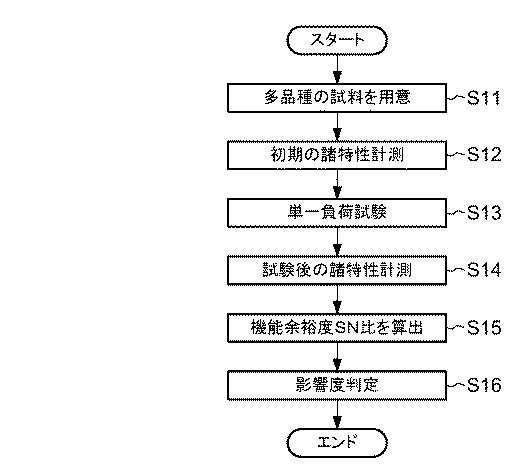
次に、図6〜図8を参照しつつ、図4に示したS3(ステップ3)の複合負荷試験に適用される負荷因子を選定する処理手順を説明する。図4に示したステップSlと同様に、まず、図6に示すように、複数の種類の電解コンデンサ(上記した第1の電子部品)を複数個ずつ準備する(S11)。次に、図4に示したステップS2と同様に、複数の電解コンデンサの初期の特性を計測する(S12)。 Next, a processing procedure for selecting a load factor to be applied to the composite load test of S3 (step 3) shown in FIG. 4 will be described with reference to FIGS. As in step S1 shown in FIG. 4, first, as shown in FIG. 6, a plurality of types of electrolytic capacitors (the first electronic components described above) are prepared one by one (S11). Next, as in step S2 shown in FIG. 4, initial characteristics of the plurality of electrolytic capacitors are measured (S12).
さらに、図7に示すように、計測対象の特性に対して影響する負荷因子を列挙する。この列挙された負荷因子の各々に関して、限界点や規格値に基づき単一負荷試験条件を策定する。複合負荷試験では、電解コンデンサ(前述した第1及び第2の電子部品)における構成材料の物性を維持し得る条件範囲内(上記の限界点以下)での負荷因子が適用される。上記の策定された単一負荷試験条件において、例えば数十時間、各負荷因子に対応する負荷を電解コンデンサに対して与える単一負荷試験を行う(S13)。なお、単一負荷試験は、複数の電解コンデンサに対して行ってもよいし、1つの電解コンデンサに対して行ってもよい。 Furthermore, as shown in FIG. 7, load factors that affect the characteristics of the measurement target are listed. For each of the listed load factors, a single load test condition is formulated based on the limit points and standard values. In the composite load test, a load factor within a condition range (below the above-mentioned limit point) capable of maintaining the physical properties of the constituent materials in the electrolytic capacitor (the first and second electronic components described above) is applied. Under the above-defined single load test conditions, for example, a single load test is performed in which a load corresponding to each load factor is applied to the electrolytic capacitor for several tens of hours (S13). The single load test may be performed on a plurality of electrolytic capacitors or a single electrolytic capacitor.
次に、単一負荷試験が完了した後、各電解コンデンサの諸特性として静電容量を計測する(S14)。なお、計測環境は、S2(ステップ2)と同様に、例えば常温及び常湿の環境である。次に、電解コンデンサ毎の、単一負荷試験前に計測した特性と単一負荷試験後に計測した特性とに基づいて、機能余裕度SN比を算出する(S15)。つまり、単一負荷試験前後における各電解コンデンサの特性の変動量(静電容量)のばらつきを示す機能余裕度SN比を求める。この場合の機能余裕度SN比も、上記した式1を用いて、例えば品質工学における静特性のSN比(望小特性のSN比)を算出するものとなる。 Next, after the single load test is completed, the capacitance is measured as various characteristics of each electrolytic capacitor (S14). Note that the measurement environment is, for example, an environment of normal temperature and normal humidity, similar to S2 (step 2). Next, the functional margin SN ratio is calculated based on the characteristics measured before the single load test and the characteristics measured after the single load test for each electrolytic capacitor (S15). That is, the function margin SN ratio indicating the variation in the variation (capacitance) of the characteristics of each electrolytic capacitor before and after the single load test is obtained. In this case, the function margin SN ratio is also calculated, for example, by using the above-described equation 1 to calculate the SN ratio of the static characteristic in quality engineering (the SN ratio of the small desired characteristic).
最後に、S15(ステップl5)で算出された機能余裕度SN比に基づき、影響度判定部15は、各負荷因子の電解コンデンサに対する影響度を判定する(S16)。つまり、影響度判定部15は、複合負荷試験で適用する負荷因子を、一つの負荷因子を与える単一負荷試験を実施した後の複数の電解コンデンサ(第1の電子部品)における特性の変動量のばらつきを基に選定する。このような影響度の判定によって、図4に示したS3(ステップ3)における複合負荷試験において同時に組み合わせて適用する妥当な負荷因子が選定される。
Finally, based on the function margin SN ratio calculated in S15 (step 15), the
図7は、電解コンデンサの例えば構成材料の限界点や、規格値を参考に試験条件案を策定した一例である。電解コンデンサの静電容量が低下する故障のメカニズムとしては、電解液のドライアップや誘電体酸化被膜の化成及び水和などが考えられる。このため、例えば温度、湿度(例えば湿度80%を50時間継続)、ヒートサイクル、逆電圧(例えば−1.5V〜−2Vを印加)、過電圧(例えば定格の1.5倍の電圧を印加)などが負荷指標(抽出要因)として挙げられる。 FIG. 7 shows an example in which test condition proposals are formulated with reference to, for example, the limit points of constituent materials of electrolytic capacitors and standard values. Possible failure mechanisms that decrease the capacitance of the electrolytic capacitor include dry-up of the electrolyte, formation of a dielectric oxide film, and hydration. For this reason, for example, temperature, humidity (for example, 80% of humidity is continued for 50 hours), heat cycle, reverse voltage (for example, applying -1.5V to -2V), overvoltage (for example, applying 1.5 times the rated voltage) Are listed as load indicators (extraction factors).
また、複合負荷試験において、負荷因子を適用するための条件は、環境的負荷因子及び電気的負荷因子から電子部品毎に適宜選定されるものである。図8は、電解コンデンサの特性(静電容量)に対する負荷因子毎の影響度、及び負荷因子毎の他の負荷因子との組み合わせの有用性を示している。ここで、図8中における項目(影響度、組み合わせの有用性)毎の、「◎」は大きい、「○」は、やや大きい、「△」は、やや小さい、「×」は小さい、をそれぞれ示している。 In the combined load test, conditions for applying the load factor are appropriately selected for each electronic component from the environmental load factor and the electrical load factor. FIG. 8 shows the usefulness of the degree of influence for each load factor on the characteristics (capacitance) of the electrolytic capacitor and combinations with other load factors for each load factor. Here, “◎” is large, “◯” is slightly large, “△” is slightly small, and “×” is small for each item (influence, usefulness of combination) in FIG. Show.
また、図9は、単一負荷試験を実施した際の(負荷因子毎の)機能余裕度SN比の算出結果を例示している。この図9は、2品種の電解コンデンサ(部品A、B)に対して、温度、湿度及び逆電圧のそれぞれの負荷因子を与えて算出された機能余裕度SN比を示している。図9に示すこの結果に基づき、影響度判定部15は、複合負荷試験で適用する複数の負荷因子を選定する。例えば、選定される複数の負荷因子は、環境負荷因子又は電気的負荷因子のうちから選定される。図9において、負荷因子が逆電圧の場合は、負荷因子が湿度の場合よりも、機能余裕度SN比が小さいことから、電解コンデンサの静電容量の低下に対して影響度が大きいことがわかる。また、例えば、逆電圧は温度との組み合わせに適しており、同時に適用することが可能である。このため、複合負荷試験において同時に適用する負荷因子として温度と逆電圧とを選定することが好ましい。
Moreover, FIG. 9 has illustrated the calculation result of the function margin SN ratio (for every load factor) at the time of implementing a single load test. FIG. 9 shows functional margin SN ratios calculated by giving load factors of temperature, humidity and reverse voltage to two types of electrolytic capacitors (components A and B). Based on this result shown in FIG. 9, the
図10は、複合負荷試験を実施した結果の一例である。図10に示すように、負荷因子として温度及び逆電圧を与える複合負荷試験は、定格電圧及び定格温度を試験条件とする信頼性試験よりも、機能余裕度SN比(利得)が小さくなっていることから、電解コンデンの静電容量の低下に対して大きく影響し、これにより、図5に示した相関近似線を得るのに適していると判断することができる。 FIG. 10 is an example of a result of performing a combined load test. As shown in FIG. 10, the composite load test that gives temperature and reverse voltage as load factors has a smaller function margin SN ratio (gain) than the reliability test with the rated voltage and rated temperature as test conditions. From this, it can be determined that it is suitable for obtaining the correlation approximation line shown in FIG. 5 because it greatly affects the decrease in the capacitance of the electrolytic capacitor.
図11は、発光ダイオード(LED:Light Emitting Diode)に対しての各負荷因子に関する試験条件の一例である。上記した電解コンデンサに対して選定される負荷因子と、発光ダイオードに対して選定される負荷因子とは異なることが想定される。発光ダイオードに対して選定される負荷因子は、電解コンデンサに対して選定される負荷因子の他、図11に示すように、振動、腐食性ガス、光などがさらに挙げられる。 FIG. 11 is an example of test conditions regarding each load factor for a light emitting diode (LED). It is assumed that the load factor selected for the electrolytic capacitor is different from the load factor selected for the light emitting diode. In addition to the load factor selected for the electrolytic capacitor, the load factor selected for the light emitting diode further includes vibration, corrosive gas, light and the like as shown in FIG.
次に、図12を参照して、電解コンデンサ(第2の電子部品)の寿命を予測する手順を説明する。図12に示すように、寿命予測の対象となる複数の種類の電解コンデンサ(上記した第2の電子部品)を複数個ずつ準備する(S21)。準備する電解コンデンサは、例えば型式や寸法を限定する必要はないものの、製品の仕様(スペック)が互いに共通するものを用意する。例えば3種類以上の品種の電解コンデンサをそれぞれ3個〜5個ほど準備する。 Next, a procedure for predicting the lifetime of the electrolytic capacitor (second electronic component) will be described with reference to FIG. As shown in FIG. 12, a plurality of types of electrolytic capacitors (second electronic components described above) to be subjected to life prediction are prepared (S21). For the electrolytic capacitor to be prepared, for example, although it is not necessary to limit the model and dimensions, those having common product specifications are prepared. For example, three to five types of electrolytic capacitors of three or more types are prepared.
次に、S2(ステップ2)を行った常温及び常湿の計測環境において、電解コンデンサ毎に初期の特性として静電容量を計測する(S22)。この場合の計測環境も、S2(ステップ2)と同様に例えば常温、常湿の環境である。初期の特性は、複合負荷試験を行う前の特性である。次いで、初期の特性が計測された各電解コンデンサに対して複合負荷試験を実施する(S23)。この際の複合負荷試験は、図4に示したS3(ステップ3)と同様の試験条件とする。 Next, in the measurement environment of normal temperature and normal humidity where S2 (step 2) is performed, the capacitance is measured as an initial characteristic for each electrolytic capacitor (S22). The measurement environment in this case is also an environment of room temperature and normal humidity, for example, as in S2 (step 2). The initial characteristic is the characteristic before the composite load test is performed. Next, a composite load test is performed on each electrolytic capacitor whose initial characteristics are measured (S23). In this case, the combined load test is performed under the same test conditions as S3 (step 3) shown in FIG.
続いて、複合負荷試験が完了した後、各電解コンデンサの特性(静電容量)を計測する(S24)。この場合の計測環境も、S2(ステップ2)と同様に例えば常温、常湿の環境である。次に、電解コンデンサ毎の、複合負荷試験前に計測した特性と複合負荷試験後に計測した特性とに基づいて、機能余裕度SN比を算出する(S25)。つまり、ばらつき取得部12は、複合負荷試験前後における各電解コンデンサ(第2の電子部品)の特性の変動量(静電容量)のばらつきを表す機能余裕度SN比を取得する。
Subsequently, after the composite load test is completed, the characteristics (capacitance) of each electrolytic capacitor are measured (S24). The measurement environment in this case is also an environment of room temperature and normal humidity, for example, as in S2 (step 2). Next, the function margin SN ratio is calculated based on the characteristics measured before the composite load test and the characteristics measured after the composite load test for each electrolytic capacitor (S25). That is, the
最後に、寿命算出部13は、相関関係記憶部11に記憶された図5に示す相関近似線(相関関係)と、ばらつき取得部12によって取得された機能余裕度SN比と、に基づいて、複数の電解コンデンサ(第2の電子部品)の寿命を算出する。
Finally, the
既述したように、本実施形態に係る電子部品の寿命予測装置10及び電子部品の寿命予測方法では、複数の負荷因子を同時に与える複合負荷試験及び品質工学における機能余裕度SN比を効果的に適用することによって、電子部品の寿命を短時間で高精度に予測することができる。
As described above, in the electronic component
以上、本発明の実施形態を説明したが、この実施形態は、例として提示したものであり、発明の範囲を限定することは意図していない。この新規な実施形態は、その他の様々な形態で実施されることが可能であり、発明の要旨を逸脱しない範囲で、種々の省略、置き換え、変更を行うことができる。この実施形態やその変形例は、発明の範囲や要旨に含まれると共に、特許請求の範囲に記載された発明とその均等の範囲に含まれる。 As mentioned above, although embodiment of this invention was described, this embodiment is shown as an example and is not intending limiting the range of invention. The novel embodiment can be implemented in various other forms, and various omissions, replacements, and changes can be made without departing from the scope of the invention. This embodiment and its modifications are included in the scope and gist of the invention, and are included in the invention described in the claims and the equivalents thereof.
10…電子部品の寿命予測装置、11…相関関係記憶部、12…ばらつき取得部、13…寿命算出部、20…電解コンデンサ。
DESCRIPTION OF
Claims (12)
前記複合負荷試験を実施した後の複数の第2の電子部品における特性の変動量のばらつきを取得するばらつき取得部と、
前記記憶部に記憶された相関関係と前記取得された特性の変動量のばらつきとに基づいて、前記複数の第2の電子部品の寿命を算出する寿命算出部と、
を備える電子部品の寿命予測装置。 A storage unit for storing a correlation between a variation in characteristic variation in the plurality of first electronic components and a lifetime of the plurality of first electronic components after performing a composite load test for simultaneously applying a plurality of load factors; ,
A variation acquisition unit that acquires variations in the amount of variation in characteristics in the plurality of second electronic components after performing the composite load test;
A lifetime calculating unit that calculates the lifetimes of the plurality of second electronic components based on the correlation stored in the storage unit and the variation in the amount of variation in the acquired characteristics;
A device for predicting the life of electronic components.
請求項1に記載の電子部品の寿命予測装置。 Each of the plurality of first and second electronic components is an electronic component having a common product specification.
The lifetime prediction apparatus of the electronic component of Claim 1.
請求項1又は2に記載の電子部品の寿命予測装置。 The load factor to be applied in the composite load test is selected based on variation in the amount of variation in characteristics of the plurality of first electronic components after performing a single load test that gives one load factor.
The lifetime prediction apparatus of the electronic component of Claim 1 or 2.
請求項1から3までのいずれか1項に記載の電子部品の寿命予測装置。 In the composite load test, a load factor within a condition range in which the physical properties of the constituent materials in the first and second electronic components can be maintained is applied.
The lifetime prediction apparatus of the electronic component of any one of Claim 1 to 3.
請求項1から4までのいずれか1項に記載の電子部品の寿命予測装置。 The combined load test is completed in a shorter test time than an accelerated degradation test in which the temperature factor is applied as a single load factor.
The lifetime prediction apparatus of the electronic component of any one of Claim 1 to 4.
請求項1から5までのいずれか1項に記載の電子部品の寿命予測装置。 The variation in the variation amount of the characteristics in the plurality of first and second electronic components is a function margin SN ratio that can be calculated as a desired characteristic of the static characteristics in quality engineering.
The lifetime prediction apparatus of the electronic component of any one of Claim 1-5.
前記複合負荷試験を実施した後の複数の第2の電子部品における特性の変動量のばらつきを取得するステップと、
前記記憶部に記憶された相関関係と前記取得された特性の変動量のばらつきとに基づいて、前記複数の第2の電子部品の寿命を算出するステップと、
を有する電子部品の寿命予測方法。 The storage unit stores the correlation between the variation in the characteristic variation in the plurality of first electronic components and the lifetime of the plurality of first electronic components after performing the composite load test that simultaneously gives a plurality of load factors. Steps,
Obtaining a variation in the amount of variation in characteristics in the plurality of second electronic components after performing the composite load test;
Calculating the lifetime of the plurality of second electronic components based on the correlation stored in the storage unit and the variation in the amount of variation in the acquired characteristics;
A method for predicting the lifetime of electronic parts having
請求項7に記載の電子部品の寿命予測方法。 Each of the plurality of first and second electronic components is an electronic component having a common product specification.
The method for predicting the lifetime of an electronic component according to claim 7.
をさらに有する請求項7又は8に記載の電子部品の寿命予測方法。 Selecting a load factor to be applied in the composite load test on the basis of variations in the amount of variation in characteristics of the plurality of first electronic components after performing a single load test that provides one load factor;
The method for predicting the lifetime of an electronic component according to claim 7 or 8, further comprising:
請求項7から9までのいずれか1項に記載の電子部品の寿命予測方法。 In the composite load test, a load factor within a condition range in which the physical properties of the constituent materials in the first and second electronic components can be maintained is applied.
The method for predicting the lifetime of an electronic component according to any one of claims 7 to 9.
請求項7から10までのいずれか1項に記載の電子部品の寿命予測方法。 The combined load test is completed in a shorter test time than an accelerated degradation test in which the temperature factor is applied as a single load factor.
The lifetime prediction method of the electronic component of any one of Claim 7-10.
請求項7から11までのいずれか1項に記載の電子部品の寿命予測方法。 The variation in the variation amount of the characteristics in the plurality of first and second electronic components is a function margin SN ratio that can be calculated as a desired characteristic of the static characteristics in quality engineering.
The method for predicting the lifetime of an electronic component according to any one of claims 7 to 11.
Priority Applications (1)
| Application Number | Priority Date | Filing Date | Title |
|---|---|---|---|
| JP2017001178A JP7118589B2 (en) | 2017-01-06 | 2017-01-06 | Electronic component life prediction device and electronic component life prediction method |
Applications Claiming Priority (1)
| Application Number | Priority Date | Filing Date | Title |
|---|---|---|---|
| JP2017001178A JP7118589B2 (en) | 2017-01-06 | 2017-01-06 | Electronic component life prediction device and electronic component life prediction method |
Publications (2)
| Publication Number | Publication Date |
|---|---|
| JP2018112410A true JP2018112410A (en) | 2018-07-19 |
| JP7118589B2 JP7118589B2 (en) | 2022-08-16 |
Family
ID=62911043
Family Applications (1)
| Application Number | Title | Priority Date | Filing Date |
|---|---|---|---|
| JP2017001178A Active JP7118589B2 (en) | 2017-01-06 | 2017-01-06 | Electronic component life prediction device and electronic component life prediction method |
Country Status (1)
| Country | Link |
|---|---|
| JP (1) | JP7118589B2 (en) |
Cited By (2)
| Publication number | Priority date | Publication date | Assignee | Title |
|---|---|---|---|---|
| JP7488410B1 (en) | 2023-05-09 | 2024-05-21 | 日機装株式会社 | Method and device for predicting light output of nitride semiconductor light emitting device |
| JP7511734B1 (en) | 2023-05-09 | 2024-07-05 | 日機装株式会社 | Method and apparatus for predicting lifetime of nitride semiconductor light emitting device |
Citations (7)
| Publication number | Priority date | Publication date | Assignee | Title |
|---|---|---|---|---|
| JP2002246391A (en) * | 2001-02-21 | 2002-08-30 | Nec Corp | Method for manufacturing semiconductor device |
| JP2006313127A (en) * | 2005-05-09 | 2006-11-16 | Hitachi Ltd | Solder connection evaluation system |
| JP2008282272A (en) * | 2007-05-11 | 2008-11-20 | Renesas Technology Corp | Design support device for semiconductor device, program and recording medium for making computer function as relevant device, and production method for semiconductor device |
| JP2012132882A (en) * | 2010-12-24 | 2012-07-12 | Mitsubishi Electric Corp | Device and method for evaluating quality of electronic components |
| JP2015002242A (en) * | 2013-06-14 | 2015-01-05 | 株式会社東芝 | Semiconductor device lifetime diagnosis method |
| US20150301121A1 (en) * | 2014-04-21 | 2015-10-22 | Samsung Electronics Co., Ltd. | Method and apparatus for estimating battery life during driving of electrical vehicle (ev) |
| JP2016217942A (en) * | 2015-05-22 | 2016-12-22 | 株式会社東芝 | Screening method |
-
2017
- 2017-01-06 JP JP2017001178A patent/JP7118589B2/en active Active
Patent Citations (7)
| Publication number | Priority date | Publication date | Assignee | Title |
|---|---|---|---|---|
| JP2002246391A (en) * | 2001-02-21 | 2002-08-30 | Nec Corp | Method for manufacturing semiconductor device |
| JP2006313127A (en) * | 2005-05-09 | 2006-11-16 | Hitachi Ltd | Solder connection evaluation system |
| JP2008282272A (en) * | 2007-05-11 | 2008-11-20 | Renesas Technology Corp | Design support device for semiconductor device, program and recording medium for making computer function as relevant device, and production method for semiconductor device |
| JP2012132882A (en) * | 2010-12-24 | 2012-07-12 | Mitsubishi Electric Corp | Device and method for evaluating quality of electronic components |
| JP2015002242A (en) * | 2013-06-14 | 2015-01-05 | 株式会社東芝 | Semiconductor device lifetime diagnosis method |
| US20150301121A1 (en) * | 2014-04-21 | 2015-10-22 | Samsung Electronics Co., Ltd. | Method and apparatus for estimating battery life during driving of electrical vehicle (ev) |
| JP2016217942A (en) * | 2015-05-22 | 2016-12-22 | 株式会社東芝 | Screening method |
Cited By (6)
| Publication number | Priority date | Publication date | Assignee | Title |
|---|---|---|---|---|
| JP7488410B1 (en) | 2023-05-09 | 2024-05-21 | 日機装株式会社 | Method and device for predicting light output of nitride semiconductor light emitting device |
| JP7511734B1 (en) | 2023-05-09 | 2024-07-05 | 日機装株式会社 | Method and apparatus for predicting lifetime of nitride semiconductor light emitting device |
| JP2024163074A (en) * | 2023-05-09 | 2024-11-21 | 日機装株式会社 | Device for predicting lifetime of semiconductor light-emitting element, and manufacturing system for semiconductor light-emitting element |
| JP2024163075A (en) * | 2023-05-09 | 2024-11-21 | 日機装株式会社 | Semiconductor light emitting device manufacturing system |
| JP2024162969A (en) * | 2023-05-09 | 2024-11-21 | 日機装株式会社 | Method and device for predicting optical output of nitride semiconductor light emitting device |
| JP7626894B2 (en) | 2023-05-09 | 2025-02-04 | 日機装株式会社 | Lifetime prediction device for semiconductor light emitting devices |
Also Published As
| Publication number | Publication date |
|---|---|
| JP7118589B2 (en) | 2022-08-16 |
Similar Documents
| Publication | Publication Date | Title |
|---|---|---|
| Gupta et al. | A review of degradation behavior and modeling of capacitors | |
| Stevens et al. | The service life of large aluminum electrolytic capacitors: effects of construction and application | |
| KR101285896B1 (en) | Battery service life judging device and battery service life judging method | |
| KR102009636B1 (en) | Method for testing performance of cell | |
| US10942222B1 (en) | Estimating a lifespan of a power supply | |
| KR102122580B1 (en) | Apparatus and method for calculating service life of capacitor | |
| JP7334887B2 (en) | Contactor life diagnosis system and method using contactor coil current | |
| WO2014103705A1 (en) | Lifetime estimation device for energy storage devices and lifetime estimation method for energy storage devices | |
| CN113655315B (en) | Method, system, device and medium for comprehensively evaluating residual life of super capacitor | |
| US10578675B2 (en) | Estimation method for battery capacity | |
| JP2013044714A (en) | Lifetime diagnosis method of electrolytic capacitor | |
| WO2014046179A1 (en) | Accumulator operation control device, accumulator operation control method, and program | |
| JP2018112410A (en) | Electronic component life prediction apparatus and electronic component life prediction method | |
| CN110763435A (en) | Semiconductor laser life estimating device, method, computer equipment and medium | |
| Kulkarni et al. | Prognostics of Power Electronics, methods and validation experiments | |
| JP2010093046A (en) | Life prediction method and device for electrolytic capacitor | |
| CN113655314A (en) | A kind of supercapacitor cycle life prediction method, system, device and medium | |
| JP2012032332A (en) | Method of diagnosing lifetime of electrolytic capacitor | |
| JP2020051996A (en) | Capacitor lifetime estimation method, lifetime estimation program thereof, information processing device, and capacitor | |
| Jánó et al. | Accelerated ageing tests of aluminum electrolytic capacitors for evaluating lifetime prediction models | |
| Hewitt et al. | Observation of electrolytic capacitor ageing behaviour for the purpose of prognostics | |
| JP4330567B2 (en) | Capacitor performance measuring apparatus and measuring method | |
| Lall et al. | Prognostics of damage accrual in SSL luminaires and drivers subjected to HTSL accelerated aging | |
| JP2016217942A (en) | Screening method | |
| JP2015153991A (en) | Electrolytic capacitor life diagnosis method |
Legal Events
| Date | Code | Title | Description |
|---|---|---|---|
| A711 | Notification of change in applicant |
Free format text: JAPANESE INTERMEDIATE CODE: A712 Effective date: 20171201 Free format text: JAPANESE INTERMEDIATE CODE: A711 Effective date: 20171201 |
|
| A621 | Written request for application examination |
Free format text: JAPANESE INTERMEDIATE CODE: A621 Effective date: 20200106 |
|
| A977 | Report on retrieval |
Free format text: JAPANESE INTERMEDIATE CODE: A971007 Effective date: 20201014 |
|
| A131 | Notification of reasons for refusal |
Free format text: JAPANESE INTERMEDIATE CODE: A131 Effective date: 20201201 |
|
| A521 | Request for written amendment filed |
Free format text: JAPANESE INTERMEDIATE CODE: A523 Effective date: 20210119 |
|
| A711 | Notification of change in applicant |
Free format text: JAPANESE INTERMEDIATE CODE: A712 Effective date: 20210208 |
|
| A521 | Request for written amendment filed |
Free format text: JAPANESE INTERMEDIATE CODE: A821 Effective date: 20210208 |
|
| A02 | Decision of refusal |
Free format text: JAPANESE INTERMEDIATE CODE: A02 Effective date: 20210406 |
|
| A521 | Request for written amendment filed |
Free format text: JAPANESE INTERMEDIATE CODE: A821 Effective date: 20210208 |
|
| C60 | Trial request (containing other claim documents, opposition documents) |
Free format text: JAPANESE INTERMEDIATE CODE: C60 Effective date: 20210615 |
|
| C22 | Notice of designation (change) of administrative judge |
Free format text: JAPANESE INTERMEDIATE CODE: C22 Effective date: 20211019 |
|
| C22 | Notice of designation (change) of administrative judge |
Free format text: JAPANESE INTERMEDIATE CODE: C22 Effective date: 20220308 |
|
| C13 | Notice of reasons for refusal |
Free format text: JAPANESE INTERMEDIATE CODE: C13 Effective date: 20220329 |
|
| A521 | Request for written amendment filed |
Free format text: JAPANESE INTERMEDIATE CODE: A523 Effective date: 20220517 |
|
| C23 | Notice of termination of proceedings |
Free format text: JAPANESE INTERMEDIATE CODE: C23 Effective date: 20220607 |
|
| C03 | Trial/appeal decision taken |
Free format text: JAPANESE INTERMEDIATE CODE: C03 Effective date: 20220705 |
|
| C30A | Notification sent |
Free format text: JAPANESE INTERMEDIATE CODE: C3012 Effective date: 20220705 |
|
| A61 | First payment of annual fees (during grant procedure) |
Free format text: JAPANESE INTERMEDIATE CODE: A61 Effective date: 20220803 |
|
| R150 | Certificate of patent or registration of utility model |
Ref document number: 7118589 Country of ref document: JP Free format text: JAPANESE INTERMEDIATE CODE: R150 |
|
| S111 | Request for change of ownership or part of ownership |
Free format text: JAPANESE INTERMEDIATE CODE: R313115 |
|
| R350 | Written notification of registration of transfer |
Free format text: JAPANESE INTERMEDIATE CODE: R350 |