JP2016152668A - Linear motor, magnet unit, stage device - Google Patents
Linear motor, magnet unit, stage device Download PDFInfo
- Publication number
- JP2016152668A JP2016152668A JP2015028193A JP2015028193A JP2016152668A JP 2016152668 A JP2016152668 A JP 2016152668A JP 2015028193 A JP2015028193 A JP 2015028193A JP 2015028193 A JP2015028193 A JP 2015028193A JP 2016152668 A JP2016152668 A JP 2016152668A
- Authority
- JP
- Japan
- Prior art keywords
- magnet
- linear motor
- main pole
- pole magnet
- magnets
- Prior art date
- Legal status (The legal status is an assumption and is not a legal conclusion. Google has not performed a legal analysis and makes no representation as to the accuracy of the status listed.)
- Pending
Links
- 230000000295 complement effect Effects 0.000 claims description 11
- 238000000034 method Methods 0.000 abstract description 12
- 238000012986 modification Methods 0.000 description 8
- 230000004048 modification Effects 0.000 description 8
- 239000000853 adhesive Substances 0.000 description 5
- 230000001070 adhesive effect Effects 0.000 description 5
- 238000004519 manufacturing process Methods 0.000 description 5
- 239000000470 constituent Substances 0.000 description 3
- 230000014509 gene expression Effects 0.000 description 2
- 238000010586 diagram Methods 0.000 description 1
- 230000000694 effects Effects 0.000 description 1
- 239000011521 glass Substances 0.000 description 1
- 239000000758 substrate Substances 0.000 description 1
Images


Classifications
-
- H—ELECTRICITY
- H02—GENERATION; CONVERSION OR DISTRIBUTION OF ELECTRIC POWER
- H02K—DYNAMO-ELECTRIC MACHINES
- H02K41/00—Propulsion systems in which a rigid body is moved along a path due to dynamo-electric interaction between the body and a magnetic field travelling along the path
- H02K41/02—Linear motors; Sectional motors
- H02K41/03—Synchronous motors; Motors moving step by step; Reluctance motors
- H02K41/031—Synchronous motors; Motors moving step by step; Reluctance motors of the permanent magnet type
-
- H—ELECTRICITY
- H02—GENERATION; CONVERSION OR DISTRIBUTION OF ELECTRIC POWER
- H02K—DYNAMO-ELECTRIC MACHINES
- H02K1/00—Details of the magnetic circuit
- H02K1/06—Details of the magnetic circuit characterised by the shape, form or construction
- H02K1/12—Stationary parts of the magnetic circuit
- H02K1/17—Stator cores with permanent magnets
-
- H—ELECTRICITY
- H02—GENERATION; CONVERSION OR DISTRIBUTION OF ELECTRIC POWER
- H02K—DYNAMO-ELECTRIC MACHINES
- H02K2213/00—Specific aspects, not otherwise provided for and not covered by codes H02K2201/00 - H02K2211/00
- H02K2213/03—Machines characterised by numerical values, ranges, mathematical expressions or similar information
Landscapes
- Engineering & Computer Science (AREA)
- Physics & Mathematics (AREA)
- Chemical & Material Sciences (AREA)
- Combustion & Propulsion (AREA)
- Electromagnetism (AREA)
- Power Engineering (AREA)
- Linear Motors (AREA)
Abstract
Description
本発明は、リニアモータに関する。 The present invention relates to a linear motor.
電気エネルギーを直線運動に変換するためにリニアモータが利用される。図1は、従来のリニアモータの斜視図である。図2は、従来のリニアモータの界磁磁石の配列を示す平面図である。 Linear motors are used to convert electrical energy into linear motion. FIG. 1 is a perspective view of a conventional linear motor. FIG. 2 is a plan view showing an arrangement of field magnets of a conventional linear motor.
図1に示すようにリニアモータ2rは、可動子10と固定子20rを備える。固定子20rは、可動子10を挟み込むように、対向配置された一対のヨーク(バックヨーク)22a,22bと、バックヨーク22a,22bそれぞれの内側側面S1a,S1bに、可動子10の可動方向(X軸方向)に沿って設けられた複数の界磁磁石24と、を備える。
As shown in FIG. 1, the
図2に示すように、複数の界磁磁石24は、主極磁石24aと、補極磁石24bと、を含む。主極磁石24a1、24a2、24a3…は、磁極ピッチにしたがい、N極およびS極が交互に現れるように貼り付けられる。隣接する2個の主極磁石24aiと24ai+1の間には、2つの主極磁石が発生する磁界に沿った磁極を有する補極磁石24biが設けられる。ただし、i=1,2,3…である。このような磁気回路の構成は、ハルバッハ配列(Halbach Array)と称され、さまざまなリニアモータに採用される。
As shown in FIG. 2, the plurality of
本発明者は、図2のハルバッハ配列について検討した結果、以下の課題を認識するに至った。補極磁石24bのない磁気回路では、主極磁石24aが発生する磁界は、ヨーク22の内部を通過する。しかしながら補極磁石24bを有するハルバッハ配列構造では、補極磁石24bが代替の磁路となり、すなわち主極磁石24aの発生する磁界が補極磁石24bを通過することとなる。
As a result of studying the Halbach array of FIG. 2, the present inventor has recognized the following problems. In a magnetic circuit without the
i番目の主極磁石24aiに着目する。主極磁石24aiのN極と、それと隣接する補極磁石24biのS極は、互いに引き合う力Fiを発生させる。同様に主極磁石24aiのN極と、それと隣接する補極磁石24bi−1のS極も、互いに引き合う力Fi−1を発生させる。その他の主極磁石24aについても同様であり、補極磁石24bによって、ヨーク22から引き離される方向に力が働く。
Attention is paid to the i-th
この主極磁石24aをヨーク22から引き離す力Fに対向するため、極力な接着剤を用いて主極磁石24aをヨーク22に貼り付けたり、主極磁石24aの側面と補極磁石24bを接着する必要が生じ、組み立て工程が複雑となり得る。
In order to oppose the force F that separates the
また、このような対策を講じたとしても、主極磁石24aや補極磁石24bの寸法バラツキ、非平坦性に起因して接着強度にばらつきが生じるため、組み立て工程中、あるいは組み立て工程後において、界磁磁石24の一部がヨーク22から剥離することを完全に防ぐことは難しい。
Even if such measures are taken, the adhesive strength varies due to dimensional variation and non-flatness of the
本発明は係る課題に鑑みてなされたものであり、そのある態様の例示的な目的のひとつは、組み立て工程、および/または組み立て後の信頼性を高めたリニアモータの提供にある。 SUMMARY OF THE INVENTION The present invention has been made in view of the above problems, and one of exemplary purposes of an embodiment thereof is to provide a linear motor with improved assembly process and / or reliability after assembly.
本発明のある態様はリニアモータに関する。リニアモータは、可動子と、固定子と、を有する。固定子は、可動子をその可動方向と垂直な方向から挟み込むように、対向して設けられた一対のバックヨークと、一対のバックヨークそれぞれの内側側面に、可動方向に沿って離間して設けられた複数の主極磁石と、隣接する2個の主極磁石の間ごとに、可動方向に隣接して設けられる第1補極磁石および第2補極磁石と、を備える。 One embodiment of the present invention relates to a linear motor. The linear motor has a mover and a stator. The stator is provided on a pair of back yokes provided opposite to each other so as to sandwich the mover from a direction perpendicular to the movable direction, and on the inner side surfaces of the pair of back yokes so as to be separated along the movable direction. A plurality of main pole magnets, and a first supplementary magnet and a second supplementary pole magnet provided adjacent to each other between the two adjacent main pole magnets in the movable direction.
この態様では、従来のハルバッハ配列において、隣接する主極磁石の間ごとに1個設けられた補極磁石を、2個に分割して設けることにより、組み立て工程において、ある主極磁石に対してバックヨークから引き離そうとする力が集中的に発生するのを抑制でき、ひいては、組み立て工程、および/または組み立て後の信頼性を高めることができる。 In this aspect, in the conventional Halbach arrangement, one auxiliary pole magnet provided between adjacent main pole magnets is divided into two pieces to provide a certain main pole magnet in the assembly process. It is possible to suppress intensive generation of a force for pulling away from the back yoke, and as a result, it is possible to improve the assembly process and / or reliability after assembly.
磁極ピッチをWpとするとき、主極磁石の幅Wa、第1補極磁石の幅Wc、第2補極磁石の幅Wdは、
Wa+Wc+Wd=Wp
0.5×Wp≦Wa≦0.9×Wp
0.1×Wp≦Wc+Wd≦0.5×Wp
を満たしてもよい。
When the magnetic pole pitch is Wp, the width Wa of the main pole magnet, the width Wc of the first auxiliary pole magnet, and the width Wd of the second auxiliary pole magnet are:
Wa + Wc + Wd = Wp
0.5 × Wp ≦ Wa ≦ 0.9 × Wp
0.1 × Wp ≦ Wc + Wd ≦ 0.5 × Wp
May be satisfied.
Wc=Wdであってもよい。 Wc = Wd may be sufficient.
主極磁石と、その両端に設けられた2個の補極磁石は、磁石ユニットとして一体構成された後に、バックヨークに組み付けられてもよい。
磁石ユニットごとにバックヨークに組み付けることにより、磁石ユニット全体としては、バックヨークとの間に吸引する力が作用する一方で、主極磁石をヨークから引き剥がそうとする力を、弱めることができる。また隣接する磁石ユニット間には吸引力が働くため、組み立て易くなる。
The main pole magnet and the two auxiliary pole magnets provided at both ends thereof may be assembled as a magnet unit and then assembled to the back yoke.
By assembling each magnet unit to the back yoke, as a whole magnet unit, a force to be attracted to the back yoke acts, while a force to peel off the main pole magnet from the yoke can be weakened. . In addition, since an attractive force acts between adjacent magnet units, it is easy to assemble.
本発明の別の態様は、ステージ装置に関する。このステージ装置は、上述のいずれかのリニアモータを備える。 Another aspect of the present invention relates to a stage apparatus. This stage apparatus includes any of the linear motors described above.
本発明の別の態様は、磁石ユニットである。この磁石ユニットは、可動子と、固定子と、を有するリニアモータに使用される。固定子は、可動子をその可動方向と垂直な方向から挟み込むように対向して設けられた一対のバックヨークを含み、一対のバックヨークそれぞれの内側側面に、可動方向に沿って磁石ユニットが複数個、配置される。磁石ユニットは、主極磁石と、主極磁石の両端に密に固着した補極磁石と、を備える。 Another aspect of the present invention is a magnet unit. This magnet unit is used for a linear motor having a mover and a stator. The stator includes a pair of back yokes provided so as to sandwich the mover from a direction perpendicular to the movable direction, and a plurality of magnet units are provided on the inner side surfaces of the pair of back yokes along the movable direction. Are arranged. The magnet unit includes a main pole magnet and an auxiliary pole magnet that is closely fixed to both ends of the main pole magnet.
なお、以上の構成要素の任意の組み合わせや本発明の構成要素や表現を、方法、装置、システムなどの間で相互に置換したものもまた、本発明の態様として有効である。 Note that any combination of the above-described constituent elements and the constituent elements and expressions of the present invention replaced with each other among methods, apparatuses, systems, and the like are also effective as an aspect of the present invention.
本発明によれば、リニアモータの組み立て工程、および/または組み立て後の信頼性を高めることができる。 ADVANTAGE OF THE INVENTION According to this invention, the assembly process of a linear motor and / or the reliability after an assembly can be improved.
以下、本発明を好適な実施の形態をもとに図面を参照しながら説明する。各図面に示される同一または同等の構成要素、部材、処理には、同一の符号を付するものとし、適宜重複した説明は省略する。また、実施の形態は、発明を限定するものではなく例示であって、実施の形態に記述されるすべての特徴やその組み合わせは、必ずしも発明の本質的なものであるとは限らない。 The present invention will be described below based on preferred embodiments with reference to the drawings. The same or equivalent components, members, and processes shown in the drawings are denoted by the same reference numerals, and repeated descriptions are omitted as appropriate. The embodiments do not limit the invention but are exemplifications, and all features and combinations thereof described in the embodiments are not necessarily essential to the invention.
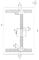
図3は、実施の形態に係るリニアモータ2の斜視図である。図4は、図3の界磁磁石の配列を示す平面図である。図中、矢印は磁極の向きを示しており、矢印先端がN極、矢印の根元がS極に相当する。
FIG. 3 is a perspective view of the
図3に示すように、リニアモータ2は、可動子10と固定子20を備える。固定子20は、一対のバックヨーク(単にヨークともいう)22a,22b、複数の界磁磁石24を備える。一対のヨーク22aおよび22bは、可動子10をその可動方向(X軸方向)と垂直な方向(Y方向)から挟み込むように対向して設けられる。
As shown in FIG. 3, the
複数の界磁磁石24は、複数の主極磁石24aおよび複数の補極磁石24c,24dを含む。複数の主極磁石24a1,24a2,24a3…は、一対のバックヨーク22a,22bそれぞれの内側側面S1a,S1bに、可動方向(X方向)に沿って設けられる。
The plurality of
また、隣接する2個の主極磁石24aの間ごとに、2個の補極磁石24c,24dが、可動方向(X方向)に隣接して設けられる。具体的には、i番目の主極磁石24aiとi+1番目の主極磁石24ai+1の間には、第1補極磁石24ciと第2補極磁石24di+1が隣接して挿入されている。
Two
第1補極磁石24ci+1の幅Wcと第2補極磁石24diの幅Wdは、それらの合計が、従来のハルバッハ配列構造の磁気回路における補極磁石24bの幅と同程度となるよう設計してもよい。
The width Wc of the first
隣接する主極磁石24aの中心間の距離を磁気ピッチWpと定義するとき、主極磁石24aの幅Waは、Wa≧0.5×Wpとすることが好ましい。このとき2個の補極磁石24cおよび24dの幅の合計Wc+Wdは、Wc+Wd≦Wa≦0.5×Wpとなる。一方、補極磁石24c,24dの効果を得るためには、それらの幅の合計Wc+Wdは、磁極ピッチWpの1/10より大きいことが望ましい。
これらの条件を勘案すると、主極磁石24a、補極磁石24c,24dそれぞれの幅は、以下の式を満たすように定めればよい。
Wa+Wc+Wd=Wp
0.5×Wp≦Wa≦0.9×Wp
0.1×Wp≦Wc+Wd≦0.5×Wp
設計および製造の簡素化の観点から、Wc=Wdとしてもよい。
When the distance between the centers of the adjacent
Taking these conditions into consideration, the widths of the
Wa + Wc + Wd = Wp
0.5 × Wp ≦ Wa ≦ 0.9 × Wp
0.1 × Wp ≦ Wc + Wd ≦ 0.5 × Wp
From the viewpoint of simplification of design and manufacturing, Wc = Wd may be set.
以上が固定子20の構成である。続いてその製造方法を説明する。固定子20は、i番目の主極磁石24aiと、その両端の第1補極磁石24ciおよび第2補極磁石24diを磁石ユニット26として一体構成した上で、磁石ユニット26を単位として組み立てることができる。図4に示されるように、偶数番目の磁石ユニット26と奇数番目の磁石ユニット26とは、補極磁石24c、補極磁石24dの方向が反対であり、したがって2種類の磁石ユニット26x,26yが用意される。
The above is the configuration of the
図5(a)〜(c)は、固定子20の製造工程を示す図である。
図5(a)に示すように、主極磁石24aの両側面に、第2補極磁石24d、第1補極磁石24cが接着剤により張り合わされ、図5(b)に示すように2種類の磁石ユニット26x,26yが構成される。そしてヨーク22の面S1に、磁石ユニット26x,26yが交互に、接着剤により貼り付けられる。隣接する磁石ユニット26x,26yの間にも接着剤を塗布してもよい。以上が固定子20の製造方法である。
FIGS. 5A to 5C are diagrams showing a manufacturing process of the
As shown in FIG. 5 (a), a second
続いて実施の形態に係るリニアモータ2の利点を説明する。従来のハルバッハ配列において、隣接する主極磁石の間ごとに1個設けられた補極磁石を、本実施の形態では、2個に分割して設けることとした。
これにより、複数の界磁磁石24、具体的には複数の主極磁石24aと複数の第1補極磁石24c、第2補極磁石24dをヨーク22に貼り合わせる際に、従来のハルバッハ配列ではなしえない順序で組み立てることができ、これにより、主極磁石24aに対して、バックヨーク22から引き離そうとする力が集中的に発生するのを抑制できる。言い換えれば、主極磁石24aの剥離を抑制しうる順序で、界磁磁石24をヨーク22に貼り付けることができる。これにより、組み立て工程、および/または組み立て後の信頼性を高めることができる。
Next, advantages of the
Thus, when the plurality of
具体的には実施の形態では特に図5(a)〜(c)に示すように、磁石ユニット26ごとにヨーク22に接着することとした。これにより、磁石ユニット26全体としては、バックヨーク22に吸引する力が作用する一方で、主極磁石24aをヨーク22から引き剥がそうとする力が弱まる。加えて隣接する磁石ユニット26間には吸引力が働くこととなる。これにより、複数の界磁磁石24をヨーク22に貼り付ける作業が容易となり、固定子20が組み立て易くなる。
Specifically, in the embodiment, as shown in FIGS. 5A to 5C, the magnet unit 26 is bonded to the
以上がリニアモータ2の利点である。続いてその用途を説明する。
図6は、実施の形態に係るリニアモータ2を用いたステージ装置100の平面図である。このステージ装置100はXYステージと称され、対象物をX方向、Y方向に位置決めする。
The above is the advantage of the
FIG. 6 is a plan view of the
ステージ装置100は、主としてYステージ120と、Xステージ130と、定盤140と、を備える。
Yステージ120は、一対のスライダ124と、一対のスライダ124の間に横架する横架材122と、を備える。横架材122の上には、Xステージ130をX方向に移動させるXリニアモータ2Xが設けられている。Xリニアモータ2Xは、横架材122に固定されX方向に延在する固定子20Yと、Xステージ130の下面に結合された可動子(コイル)10Yとを備える。かくしてXリニアモータ2Xの可動子10を制御することにより、Xステージ130がX方向に位置決めされる。
The
The
定盤140の両端には、一対のYリニアモータ2Yが設けられる。Yリニアモータ2Yはそれぞれ、可動子10および固定子20を備える。Yリニアモータ2Yの固定子20には、上述のスライダ124が固定される。Yリニアモータ2Yの可動子10を制御することによりYステージ120がY方向に位置決めされる。
A pair of Y
以上がステージ装置100の構成である。実施の形態に係るリニアモータ2は、ステージ装置100のXリニアモータ2XあるいはYリニアモータ2Yに好適に用いることができる。ステージ装置100は、露光装置におけるウェハやガラス基板の位置決めに用いることができ、あるいは走査型電子顕微鏡(SEM)に使用されるアクチュエータなどにも利用可能である。
The above is the configuration of the
以上、本発明について、実施の形態をもとに説明した。この実施の形態は例示であり、それらの各構成要素や各処理プロセスの組み合わせにいろいろな変形例が可能なこと、またそうした変形例も本発明の範囲にあることは当業者に理解されるところである。以下、こうした変形例について説明する。 The present invention has been described based on the embodiments. This embodiment is an exemplification, and it will be understood by those skilled in the art that various modifications can be made to combinations of the respective constituent elements and processing processes, and such modifications are within the scope of the present invention. is there. Hereinafter, such modifications will be described.
(変形例1)
実施の形態では、図5(a)〜(c)に示すように、主極磁石24aと、その両端の第1補極磁石24c、第2補極磁石24dをひとつの磁石ユニット26として構成した後に、ヨーク22に組み付けたが本発明はそれには限定されない。たとえば磁石ユニット26xと磁石ユニット26yを接着して、ひとつの磁石ユニット26xyを構成し、この磁石ユニット26xyを単位として磁石ユニット26に接着してもよい。
(Modification 1)
In the embodiment, as shown in FIGS. 5A to 5C, the
(変形例2)
あるいは、はじめに複数の主極磁石24aを横方向に所定間隔で固定子20に接着した後に、第1補極磁石24c、第2補極磁石24dを、間隔を埋めるように接着してもよい。すなわち界磁磁石24のヨーク22の組み付け順序は特に限定されず、界磁磁石24の剥離を防止可能な順序であれば、任意の順序で組み立ててもよい。
(Modification 2)
Alternatively, first, a plurality of
(変形例3)
実施の形態では、第1補極磁石24c、第2補極磁石24dそれぞれが、主極磁石24aの磁極の方向と垂直方向に着磁される場合を説明したが本発明はそれには限定されない。第1補極磁石24c、第2補極磁石24dは、垂直方向に対して勾配をもって着磁されてもよい。
(Modification 3)
In the embodiment, the case has been described in which each of the first
(変形例4)
実施の形態では第1補極磁石24cと第2補極磁石24dの幅Wc,Wdが等しい場合を説明したが、磁気ピッチWpが一定となる条件下で、それらの幅を異ならしてもよい。
(Modification 4)
In the embodiment, the case where the widths Wc and Wd of the first
実施の形態にもとづき、具体的な語句を用いて本発明を説明したが、実施の形態は、本発明の原理、応用を示しているにすぎず、実施の形態には、請求の範囲に規定された本発明の思想を逸脱しない範囲において、多くの変形例や配置の変更が認められる。 Although the present invention has been described using specific terms based on the embodiments, the embodiments only illustrate the principles and applications of the present invention, and the embodiments are defined in the claims. Many variations and modifications of the arrangement are permitted without departing from the spirit of the present invention.
2…リニアモータ、10…可動子、20…固定子、22…ヨーク、24…界磁磁石、24a…主極磁石、24b…補極磁石、24c…第1補極磁石、24d…第2補極磁石、26…磁石ユニット、100…ステージ装置、2X…Xリニアモータ、2Y…Yリニアモータ、120…Yステージ、122…横架材、124…スライダ、130…Xステージ、S1…内側側面。 2 ... linear motor, 10 ... mover, 20 ... stator, 22 ... yoke, 24 ... field magnet, 24a ... main pole magnet, 24b ... complement magnet, 24c ... first complement magnet, 24d ... second complement Polar magnet, 26 ... magnet unit, 100 ... stage device, 2X ... X linear motor, 2Y ... Y linear motor, 120 ... Y stage, 122 ... horizontal member, 124 ... slider, 130 ... X stage, S1 ... inner side surface.
Claims (5)
前記固定子は、
前記可動子をその可動方向と垂直な方向から挟み込むように、対向して設けられた一対のバックヨークと、
前記一対のバックヨークそれぞれの内側側面に、前記可動方向に沿って離間して設けられた複数の主極磁石と、
隣接する2個の主極磁石の間ごとに、前記可動方向に隣接して設けられる第1補極磁石および第2補極磁石と、
を備えることを特徴とするリニアモータ。 A linear motor having a mover and a stator,
The stator is
A pair of back yokes provided facing each other so as to sandwich the mover from a direction perpendicular to the movable direction;
A plurality of main pole magnets provided on the inner side surfaces of each of the pair of back yokes and spaced apart along the movable direction;
A first complementary pole magnet and a second complementary pole magnet provided adjacent to each other between the two adjacent main pole magnets in the movable direction;
A linear motor comprising:
Wa+Wc+Wd=Wp
0.5×Wp≦Wa≦0.9×Wp
0.1×Wp≦Wc+Wd≦0.5×Wp
を満たすことを特徴とする請求項1に記載のリニアモータ。 When the magnetic pole pitch is Wp, the width Wa of the main pole magnet, the width Wc of the first auxiliary pole magnet, and the width Wd of the second auxiliary pole magnet are:
Wa + Wc + Wd = Wp
0.5 × Wp ≦ Wa ≦ 0.9 × Wp
0.1 × Wp ≦ Wc + Wd ≦ 0.5 × Wp
The linear motor according to claim 1, wherein:
前記固定子は、前記可動子をその可動方向と垂直な方向から挟み込むように対向して設けられた一対のバックヨークを含み、前記一対のバックヨークそれぞれの内側側面に、前記可動方向に沿って前記磁石ユニットが複数個、配置され、
前記磁石ユニットは、
主極磁石と、
前記主極磁石の両端に密に固着した補極磁石と、
を備えることを特徴とする磁石ユニット。 A magnet unit used for a linear motor having a mover and a stator,
The stator includes a pair of back yokes provided so as to sandwich the mover from a direction perpendicular to the movable direction, and on the inner side surfaces of the pair of back yokes along the movable direction. A plurality of the magnet units are arranged,
The magnet unit is
A main pole magnet;
An auxiliary pole magnet closely fixed to both ends of the main pole magnet;
A magnet unit comprising:
Priority Applications (3)
| Application Number | Priority Date | Filing Date | Title |
|---|---|---|---|
| JP2015028193A JP2016152668A (en) | 2015-02-17 | 2015-02-17 | Linear motor, magnet unit, stage device |
| TW105103836A TWI586080B (en) | 2015-02-17 | 2016-02-04 | A linear motor, a magnet unit, and a stage device |
| US15/043,948 US10381911B2 (en) | 2015-02-17 | 2016-02-15 | Linear motor, magnet unit, and stage device |
Applications Claiming Priority (1)
| Application Number | Priority Date | Filing Date | Title |
|---|---|---|---|
| JP2015028193A JP2016152668A (en) | 2015-02-17 | 2015-02-17 | Linear motor, magnet unit, stage device |
Publications (1)
| Publication Number | Publication Date |
|---|---|
| JP2016152668A true JP2016152668A (en) | 2016-08-22 |
Family
ID=56622402
Family Applications (1)
| Application Number | Title | Priority Date | Filing Date |
|---|---|---|---|
| JP2015028193A Pending JP2016152668A (en) | 2015-02-17 | 2015-02-17 | Linear motor, magnet unit, stage device |
Country Status (3)
| Country | Link |
|---|---|
| US (1) | US10381911B2 (en) |
| JP (1) | JP2016152668A (en) |
| TW (1) | TWI586080B (en) |
Cited By (7)
| Publication number | Priority date | Publication date | Assignee | Title |
|---|---|---|---|---|
| CN107792677A (en) * | 2016-08-30 | 2018-03-13 | 细美事有限公司 | Noncontact driving module and the conveying device with the module |
| KR20180059081A (en) * | 2016-11-25 | 2018-06-04 | 세메스 주식회사 | Magnetic levitation transfer apparatus |
| WO2019130646A1 (en) * | 2017-12-28 | 2019-07-04 | Kyb株式会社 | Cylindrical linear motor |
| WO2019202765A1 (en) * | 2018-04-17 | 2019-10-24 | Kyb株式会社 | Cylindrical linear motor |
| JP2019187226A (en) * | 2018-04-17 | 2019-10-24 | Kyb株式会社 | Cylindrical linear motor |
| JPWO2022196128A1 (en) * | 2021-03-18 | 2022-09-22 | ||
| US11527929B2 (en) | 2019-09-24 | 2022-12-13 | Seiko Epson Corporation | Motor for improving flux content and robot comprising the same |
Families Citing this family (2)
| Publication number | Priority date | Publication date | Assignee | Title |
|---|---|---|---|---|
| TWI664795B (en) * | 2017-03-24 | 2019-07-01 | 日商日立金屬股份有限公司 | Linear motor |
| DE102019113296A1 (en) * | 2019-05-20 | 2020-11-26 | Physik Instrumente (Pi) Gmbh & Co. Kg | Two-axis positioning device |
Citations (7)
| Publication number | Priority date | Publication date | Assignee | Title |
|---|---|---|---|---|
| WO2006035835A1 (en) * | 2004-09-29 | 2006-04-06 | Nikon Corporation | Magnetic field generation device, electromagnetic actuator, stage device, exposure device, and device manufacturing method |
| JP2010050440A (en) * | 2008-07-23 | 2010-03-04 | Hitachi Metals Ltd | R-fe-b-based sintered magnet unit, magnetic circuit for linear motor using the same, and method of manufacturing them |
| JP2010063201A (en) * | 2008-09-01 | 2010-03-18 | Mitsubishi Electric Corp | Linear motor |
| JP2010104136A (en) * | 2008-10-23 | 2010-05-06 | Mitsubishi Electric Corp | Linear motor |
| US20120313473A1 (en) * | 2011-04-18 | 2012-12-13 | Chen jin-tao | Synchronous permanent magnet machine |
| JP2013106458A (en) * | 2011-11-15 | 2013-05-30 | Yaskawa Electric Corp | Linear motor |
| WO2014019438A1 (en) * | 2012-07-31 | 2014-02-06 | 上海微电子装备有限公司 | Linear motor and platform device |
Family Cites Families (8)
| Publication number | Priority date | Publication date | Assignee | Title |
|---|---|---|---|---|
| US6104108A (en) * | 1998-12-22 | 2000-08-15 | Nikon Corporation | Wedge magnet array for linear motor |
| JP2001217183A (en) * | 2000-02-04 | 2001-08-10 | Nikon Corp | Motor apparatus, stage apparatus, exposure apparatus, and device manufacturing method |
| US20030125253A1 (en) * | 2000-03-24 | 2003-07-03 | Yoshio Taniyama | Novel protein, process for producing the same and use therof |
| JP5223290B2 (en) * | 2007-10-22 | 2013-06-26 | 日立金属株式会社 | Magnetic field generator |
| US20090106037A1 (en) * | 2007-10-23 | 2009-04-23 | Infosys Technologies Ltd. | Electronic book locator |
| KR20140084238A (en) * | 2011-10-27 | 2014-07-04 | 더 유니버시티 오브 브리티쉬 콜롬비아 | Displacement devices and methods for fabrication, use and control of same |
| JP2013258894A (en) * | 2012-05-18 | 2013-12-26 | Thk Co Ltd | Linear motor |
| US9906111B2 (en) * | 2014-10-21 | 2018-02-27 | Xiuhong Sun | Fine element magnet array |
-
2015
- 2015-02-17 JP JP2015028193A patent/JP2016152668A/en active Pending
-
2016
- 2016-02-04 TW TW105103836A patent/TWI586080B/en active
- 2016-02-15 US US15/043,948 patent/US10381911B2/en not_active Expired - Fee Related
Patent Citations (7)
| Publication number | Priority date | Publication date | Assignee | Title |
|---|---|---|---|---|
| WO2006035835A1 (en) * | 2004-09-29 | 2006-04-06 | Nikon Corporation | Magnetic field generation device, electromagnetic actuator, stage device, exposure device, and device manufacturing method |
| JP2010050440A (en) * | 2008-07-23 | 2010-03-04 | Hitachi Metals Ltd | R-fe-b-based sintered magnet unit, magnetic circuit for linear motor using the same, and method of manufacturing them |
| JP2010063201A (en) * | 2008-09-01 | 2010-03-18 | Mitsubishi Electric Corp | Linear motor |
| JP2010104136A (en) * | 2008-10-23 | 2010-05-06 | Mitsubishi Electric Corp | Linear motor |
| US20120313473A1 (en) * | 2011-04-18 | 2012-12-13 | Chen jin-tao | Synchronous permanent magnet machine |
| JP2013106458A (en) * | 2011-11-15 | 2013-05-30 | Yaskawa Electric Corp | Linear motor |
| WO2014019438A1 (en) * | 2012-07-31 | 2014-02-06 | 上海微电子装备有限公司 | Linear motor and platform device |
Cited By (15)
| Publication number | Priority date | Publication date | Assignee | Title |
|---|---|---|---|---|
| KR101854034B1 (en) * | 2016-08-30 | 2018-05-02 | 세메스 주식회사 | Contactless driving module and transfer apparatus having the same |
| CN107792677A (en) * | 2016-08-30 | 2018-03-13 | 细美事有限公司 | Noncontact driving module and the conveying device with the module |
| CN107792677B (en) * | 2016-08-30 | 2019-10-29 | 细美事有限公司 | Noncontact driving module and conveying device with the module |
| KR20180059081A (en) * | 2016-11-25 | 2018-06-04 | 세메스 주식회사 | Magnetic levitation transfer apparatus |
| KR102575953B1 (en) | 2016-11-25 | 2023-09-07 | 세메스 주식회사 | Magnetic levitation transfer apparatus |
| US11245321B2 (en) | 2017-12-28 | 2022-02-08 | Kyb Corporation | Cylindrical linear motor |
| WO2019130646A1 (en) * | 2017-12-28 | 2019-07-04 | Kyb株式会社 | Cylindrical linear motor |
| JP2019122072A (en) * | 2017-12-28 | 2019-07-22 | Kyb株式会社 | Cylindrical linear motor |
| JP2019187226A (en) * | 2018-04-17 | 2019-10-24 | Kyb株式会社 | Cylindrical linear motor |
| WO2019202765A1 (en) * | 2018-04-17 | 2019-10-24 | Kyb株式会社 | Cylindrical linear motor |
| US11527929B2 (en) | 2019-09-24 | 2022-12-13 | Seiko Epson Corporation | Motor for improving flux content and robot comprising the same |
| JPWO2022196128A1 (en) * | 2021-03-18 | 2022-09-22 | ||
| WO2022196128A1 (en) * | 2021-03-18 | 2022-09-22 | トヨタ自動車株式会社 | Magnet arrangement method, and method for manufacturing rotor |
| JP7533766B2 (en) | 2021-03-18 | 2024-08-14 | トヨタ自動車株式会社 | Rotor manufacturing method |
| US12348086B2 (en) | 2021-03-18 | 2025-07-01 | Toyota Jidosha Kabushiki Kaisha | Magnet arrangement method and rotor manufacturing method |
Also Published As
| Publication number | Publication date |
|---|---|
| US10381911B2 (en) | 2019-08-13 |
| US20160241120A1 (en) | 2016-08-18 |
| TWI586080B (en) | 2017-06-01 |
| TW201633661A (en) | 2016-09-16 |
Similar Documents
| Publication | Publication Date | Title |
|---|---|---|
| JP2016152668A (en) | Linear motor, magnet unit, stage device | |
| CN106469968B (en) | Linear motor | |
| JP5253114B2 (en) | Linear motor | |
| EP3076531A1 (en) | Flat voice coil motor | |
| CN101978585A (en) | Multi-degree-of-freedom actuator and stage device | |
| US20160006330A1 (en) | Actuator | |
| WO2016159034A1 (en) | Linear motor armature and linear motor | |
| JP5648873B2 (en) | Linear motor | |
| JP2016163366A (en) | Assembly method of magnetic field generating device and magnetic field generating device | |
| JP2022035832A (en) | Permanent magnetic field, manufacturing method, and linear motor | |
| KR20120036286A (en) | Linear motor and stage device | |
| EP3326276B1 (en) | Transverse flux linear motor | |
| JP2011193703A (en) | Linear motor pair, moving stage, and electron microscope | |
| JPWO2014192058A1 (en) | Linear motor and stage device | |
| JP6732686B2 (en) | Linear motor, stage device | |
| JP2017175765A (en) | Linear motor and stage device | |
| JP6067418B2 (en) | Linear motor | |
| CN209250462U (en) | An airfoil linear motor | |
| JP2018148760A (en) | Linear motor | |
| TWI647895B (en) | Linear motor, stage device | |
| KR100497730B1 (en) | Multi pole magnet array assembling structure using jig | |
| JP2016187278A (en) | Linear motor | |
| JP5514513B2 (en) | Linear motor | |
| JP7391820B2 (en) | Electric motor | |
| JP2016171739A (en) | Linear motor and stage device |
Legal Events
| Date | Code | Title | Description |
|---|---|---|---|
| A621 | Written request for application examination |
Free format text: JAPANESE INTERMEDIATE CODE: A621 Effective date: 20170718 |
|
| A977 | Report on retrieval |
Free format text: JAPANESE INTERMEDIATE CODE: A971007 Effective date: 20180412 |
|
| A131 | Notification of reasons for refusal |
Free format text: JAPANESE INTERMEDIATE CODE: A131 Effective date: 20180424 |
|
| A521 | Request for written amendment filed |
Free format text: JAPANESE INTERMEDIATE CODE: A523 Effective date: 20180622 |
|
| A131 | Notification of reasons for refusal |
Free format text: JAPANESE INTERMEDIATE CODE: A131 Effective date: 20181113 |
|
| A521 | Request for written amendment filed |
Free format text: JAPANESE INTERMEDIATE CODE: A523 Effective date: 20190111 |
|
| A02 | Decision of refusal |
Free format text: JAPANESE INTERMEDIATE CODE: A02 Effective date: 20190702 |