[go: up one dir, main page]

JP2016109916A - Image formation device - Google Patents

Image formation device Download PDF

Info

Publication number
JP2016109916A
JP2016109916A JP2014248020A JP2014248020A JP2016109916A JP 2016109916 A JP2016109916 A JP 2016109916A JP 2014248020 A JP2014248020 A JP 2014248020A JP 2014248020 A JP2014248020 A JP 2014248020A JP 2016109916 A JP2016109916 A JP 2016109916A
Authority
JP
Japan
Prior art keywords
developer
container
side coupling
developer storage
image forming
Prior art date
Legal status (The legal status is an assumption and is not a legal conclusion. Google has not performed a legal analysis and makes no representation as to the accuracy of the status listed.)
Pending
Application number
JP2014248020A
Other languages
Japanese (ja)
Inventor
徹平 菊地
Teppei Kikuchi
徹平 菊地
晃一 山▲崎▼
Koichi Yamazaki
晃一 山▲崎▼
久保 達哉
Tatsuya Kubo
達哉 久保
篤 中本
Atsushi Nakamoto
篤 中本
慎之介 腰塚
Shinnosuke Koshizuka
慎之介 腰塚
一範 鈴木
Kazunori Suzuki
一範 鈴木
Current Assignee (The listed assignees may be inaccurate. Google has not performed a legal analysis and makes no representation or warranty as to the accuracy of the list.)
Ricoh Co Ltd
Original Assignee
Ricoh Co Ltd
Priority date (The priority date is an assumption and is not a legal conclusion. Google has not performed a legal analysis and makes no representation as to the accuracy of the date listed.)
Filing date
Publication date
Application filed by Ricoh Co Ltd filed Critical Ricoh Co Ltd
Priority to JP2014248020A priority Critical patent/JP2016109916A/en
Publication of JP2016109916A publication Critical patent/JP2016109916A/en
Pending legal-status Critical Current

Links

Images

Landscapes

  • Dry Development In Electrophotography (AREA)
  • Control Or Security For Electrophotography (AREA)

Abstract

PROBLEM TO BE SOLVED: To provide an image formation device which prevents a pulling-out force for a developer storage container from increasing even when lock of a drive motor occurs.SOLUTION: An image formation device comprises: a developer storage container which can be detachably attached to an image formation device body; a body side coupling member such as a drive side coupling which is provided in the image formation device body and is rotatable; a drive source such as a supply drive motor 81 which rotationally drives the body side coupling member; a container side coupling member such as a driven side coupling which is provided in a developer storage container, brought into contact with the body side coupling member and transmits a drive force from a drive source to an agitation member; load detection means such as a voltage detection element of a motor driver 88 which detects a load applied to the drive source; and control means such as a control part 210 which controls the drive source so as to stop by performing a reverse operation for rotating in a direction opposite to the direction of rotating the body side coupling member so as to agitate a developer when the load detection means detects that the load is equal to or greater than a fixed level.SELECTED DRAWING: Figure 17

Description

本発明は、画像形成装置に関する。   The present invention relates to an image forming apparatus.

プリンタ、複写機、ファクシミリ、プロッタ等又はそれら複数の機能を備えた複合機等の電子写真方式の画像形成装置では、トナーなどの現像剤を現像装置に補給するために、現像剤を収納し、画像形成装置本体に対して着脱可能な現像剤収納容器が用いられている。現像剤収納容器(トナーカートリッジとも称される)内に収納されているトナーを含む現像剤を攪拌する攪拌手段や攪拌部材を備えた装置は、特許文献1を始めとして多数知られている。   In an electrophotographic image forming apparatus such as a printer, a copying machine, a facsimile machine, a plotter, or a multi-function machine having a plurality of functions, the developer is stored in order to supply developer such as toner to the developing device, A developer container that can be attached to and detached from the image forming apparatus main body is used. Many devices including agitating means and agitating members for agitating a developer containing toner accommodated in a developer accommodating container (also referred to as a toner cartridge) are known, including Patent Document 1.

特許文献1には、トナー収納容器が過負荷状態になった場合に、人手を介さずに装置側で凝縮したトナーを解し、正常にトナー補給を行うことを目的として、この目的を達成する構成が開示されている。具体的には、トナー収納容器が過負荷状態であると判定した場合に、攪拌手段を駆動する駆動手段により攪拌手段を繰り返し正逆回転させるリトライ制御を行う制御手段を備えている。   Japanese Patent Application Laid-Open No. H10-228667 achieves this object for the purpose of releasing toner condensed on the apparatus side without manual intervention and replenishing toner normally when the toner storage container is overloaded. A configuration is disclosed. Specifically, it is provided with control means for performing retry control for repeatedly rotating the stirring means forward and backward by a driving means for driving the stirring means when it is determined that the toner storage container is in an overload state.

しかしながら、従来の画像形成装置では、以下の問題がある。トナー収納容器を引き抜く際にカップリング同士が噛み合っている状態であると、画像形成装置本体からトナー収納容器を離脱するときの引き抜き力が増大し、引き抜きが困難になることがあった。   However, the conventional image forming apparatus has the following problems. If the coupling is engaged when the toner storage container is pulled out, the pulling force when the toner storage container is detached from the image forming apparatus main body is increased, and it may be difficult to pull out the toner storage container.

本発明は、上述の課題に鑑みてなされたものであり、駆動モータのロックが発生した際でも、現像剤収納容器の引く抜き力が増大しない画像形成装置を提供することを目的とする。   SUMMARY An advantage of some aspects of the invention is that it provides an image forming apparatus in which a pulling force of a developer container is not increased even when a drive motor is locked.

上記目的を達成するために、本発明は、現像剤を収納する現像剤収納部と該現像剤収納部内の現像剤を攪拌する回転可能な攪拌部材とを有し、画像形成装置本体に対して着脱可能な現像剤収納容器と、前記画像形成装置本体に設けられ、回転可能な本体側カップリング部材と、前記本体側カップリング部材を回転駆動させる駆動源と、前記現像剤収納容器に設けられ、前記本体側カップリング部材と接触し、前記駆動源からの駆動力を前記攪拌部材に伝達する容器側カップリング部材と、前記駆動源に掛かる負荷を検知する負荷検知手段と、前記負荷検知手段によって前記負荷が一定以上であると検知された場合に、前記本体側カップリング部材を現像剤を攪拌すべく回転していた方向と逆方向に回転する逆転動作を行い停止するように前記駆動源を制御する制御手段と、を備える画像形成装置である。   In order to achieve the above object, the present invention has a developer accommodating portion for accommodating a developer and a rotatable agitating member for agitating the developer in the developer accommodating portion, with respect to the image forming apparatus main body. A removable developer storage container, a main body side coupling member provided in the main body of the image forming apparatus and rotatable, a drive source for rotationally driving the main body side coupling member, and a developer storage container. A container side coupling member that contacts the main body side coupling member and transmits a driving force from the driving source to the stirring member, a load detection unit that detects a load applied to the driving source, and the load detection unit When the load is detected to be above a certain level, the main body side coupling member is rotated in the direction opposite to the direction in which the main body side coupling member was rotated to stir the developer, and is stopped so as to stop. And control means for controlling the Dogen, an image forming apparatus comprising a.

本発明によれば、上記構成により、駆動源(例えば駆動モータ)の異常が発生した際でも、引く抜き力を増大させずに現像剤収納容器を容易に引く抜くことができる画像形成装置を提供することができる。   According to the present invention, the above configuration provides an image forming apparatus capable of easily pulling out the developer container without increasing the pulling force even when an abnormality occurs in the drive source (for example, drive motor). can do.

本発明の一実施形態に係る画像形成装置の一例としての複写機の概略的な全体構成図である。1 is a schematic overall configuration diagram of a copying machine as an example of an image forming apparatus according to an embodiment of the present disclosure. 図1の複写機の外観斜視図である。FIG. 2 is an external perspective view of the copying machine of FIG. 1. 現像装置及び感光体の概略構成図である。It is a schematic block diagram of a developing device and a photoreceptor. 各色の現像装置と、現像装置にプレミックストナーを補給する現像剤補給装置全体の構成を示す簡略的な斜視図である。FIG. 3 is a simplified perspective view showing the configuration of each color developing device and the entire developer replenishing device that replenishes the developing device with premix toner. K色用の現像剤収納容器の斜視図である。It is a perspective view of a developer storage container for K color. カラー用の現像剤収納容器の斜視図である。It is a perspective view of a developer storage container for color. カラー用の現像剤収納容器の断面図である。It is sectional drawing of the developing agent storage container for colors. カラー用の現像剤収納容器断面斜視図である。FIG. 2 is a cross-sectional perspective view of a color developer storage container. K色用の現像剤収納容器の断面斜視図である。It is a cross-sectional perspective view of a developer storage container for K color. K用の現像剤収納容器のカップリング取り付け部周辺を示す拡大図である。FIG. 4 is an enlarged view showing the vicinity of a coupling attachment portion of a developer storage container for K. 現像剤収納容器の容器保持部周辺を示す斜視図である。FIG. 6 is a perspective view showing the vicinity of a container holding portion of a developer storage container. 現像剤供給駆動部を示す斜視図である。It is a perspective view which shows a developing agent supply drive part. 駆動側のカップリングと現像剤収納容器の被駆動側のカップリングとが係合している状態を示す拡大斜視図である。FIG. 4 is an enlarged perspective view showing a state in which a driving side coupling and a driven side coupling of a developer container are engaged. サブホッパの構成を示す斜視図である。It is a perspective view which shows the structure of a sub hopper. サブホッパの内部構造を示す斜視図である。It is a perspective view which shows the internal structure of a sub hopper. サブホッパ内の現像剤貯留部と搬送部とを示す図である。It is a figure which shows the developer storage part and conveyance part in a sub hopper. 上記一実施形態の主な制御構成の一例を示すブロック図である。It is a block diagram which shows an example of the main control structures of the said one Embodiment. 上記一実施形態の動作順序を示すフローチャートである。It is a flowchart which shows the operation | movement order of the said one Embodiment.

以下、図を参照して実施例を含む本発明の実施形態を詳細に説明する。実施形態等に亘り、同一の機能及び形状等を有する構成要素(部材や構成部品)等については、混同の虞がない限り同一符号を付すことにより一度説明した後ではその説明を省略する。図及び説明の簡明化を図るため、図に表されるべき構成要素であっても、その図において特別に説明する必要がない構成要素は適宜断わりなく省略することがある。   DESCRIPTION OF EMBODIMENTS Hereinafter, embodiments of the present invention including examples will be described in detail with reference to the drawings. In the embodiments and the like, components (members and components) having the same functions and shapes are denoted by the same reference numerals unless they are confused, and the description thereof is omitted. In order to simplify the drawings and the description, even if the components are to be represented in the drawings, the components that do not need to be specifically described in the drawings may be omitted as appropriate.

まず、図1を参照して、本発明を適用した画像形成装置の一例として、複数の感光体が並んで配置されたタンデム型のカラーレーザ複写機(以下、単に複写機という)について説明する。図1は、本発明の一実施形態に係る画像形成装置としての複写機の概略的な全体構成図である。
図1に示す複写機は、画像形成部であるプリンタ部100、これを載せる給紙装置200、プリンタ部100の上に固定されたスキャナ300などを備えている。また、複写機は、スキャナ300の上に固定された原稿自動搬送装置400なども備えている。
First, referring to FIG. 1, a tandem type color laser copying machine (hereinafter simply referred to as a copying machine) in which a plurality of photoreceptors are arranged side by side will be described as an example of an image forming apparatus to which the present invention is applied. FIG. 1 is a schematic overall configuration diagram of a copying machine as an image forming apparatus according to an embodiment of the present invention.
The copying machine shown in FIG. 1 includes a printer unit 100 as an image forming unit, a paper feeding device 200 on which the printer unit 100 is placed, a scanner 300 fixed on the printer unit 100, and the like. The copying machine also includes an automatic document feeder 400 fixed on the scanner 300.

プリンタ部100は、イエロー(Y)、マゼンダ(M)、シアン(C)、黒(K)の各色の画像を形成するための4組のプロセスカートリッジ18Y,18M,18C,18Kからなる画像形成ユニット20を備えている。各符号の数字に添字として付されたY,M,C,Kは、イエロー、シアン、マゼンダ、ブラック用の部材であることを示している(以下同様)。プリンタ部100には、プロセスカートリッジ18Y,18M,18C,18Kの他に、光書込ユニット21、中間転写ユニット17、2次転写装置22、レジストローラ対49、ベルト定着方式の定着装置25などが配設されている。尚、「配設」とは、配置して設けることや、位置を決めて設けることを意味する。   The printer unit 100 includes an image forming unit including four sets of process cartridges 18Y, 18M, 18C, and 18K for forming images of each color of yellow (Y), magenta (M), cyan (C), and black (K). 20 is provided. Y, M, C, and K added as subscripts to the numerals of the respective symbols indicate members for yellow, cyan, magenta, and black (the same applies hereinafter). In addition to the process cartridges 18Y, 18M, 18C, and 18K, the printer unit 100 includes an optical writing unit 21, an intermediate transfer unit 17, a secondary transfer device 22, a registration roller pair 49, a belt fixing type fixing device 25, and the like. It is arranged. In addition, “arrangement” means that it is provided by being arranged or provided at a predetermined position.

光書込ユニット21は、光源、ポリゴンミラー、f−θレンズ、反射ミラーなどを有し、画像データに基づいて後述の感光体の表面にレーザ光を照射する。プロセスカートリッジ18Y,18M,18C,18Kは、像担持体としてのドラム状の感光体1、帯電器、現像装置4、ドラムクリーニング装置、除電器などを有している。   The optical writing unit 21 includes a light source, a polygon mirror, an f-θ lens, a reflection mirror, and the like, and irradiates the surface of a photoconductor described later with laser light based on image data. The process cartridges 18Y, 18M, 18C, and 18K include a drum-shaped photosensitive member 1 as an image carrier, a charger, a developing device 4, a drum cleaning device, a static eliminator, and the like.

4組のプロセスカートリッジ18Y,18M,18C,18Kは、特記する内容を除き、画像形成する色が異なる以外はほぼ同様の構成であるため、以下、イエロー用のプロセスカートリッジ18Yを代表して説明する。尚、各現像装置4Y,4M,4C,4Kは、使用するトナーの色が異なる2成分現像方式の現像装置であり、各色の現像装置内にはトナーとキャリアとを含む2成分現像剤が収容されている。   Since the four process cartridges 18Y, 18M, 18C, and 18K have substantially the same configuration except for the color for image formation, except for special contents, the process cartridge 18Y for yellow will be described below as a representative. . Each of the developing devices 4Y, 4M, 4C, and 4K is a two-component developing type developing device that uses different colors of toner, and each color developing device contains a two-component developer containing toner and a carrier. Has been.

帯電手段たる帯電器によって、感光体1Yの表面は一様に帯電される。帯電処理が施された感光体1Yの表面には、光書込ユニット21によって変調及び偏向されたレーザ光が照射される。すると、感光体1Y表面の照射部(露光部)の電位が減衰する。この減衰により、感光体1Y表面にY用の静電潜像が形成される。形成されたY用の静電潜像は現像手段たる現像装置4Yによって現像されてYトナー像となる。
Y用の感光体1Y上に形成されたYトナー像は、後述の中間転写ベルト101に1次転写される。1次転写後の感光体1Yの表面は、ドラムクリーニング装置によって転写残トナー等がクリーニングされる。Y用のプロセスカートリッジ18Yにおいて、上記ドラムクリーニング装置によってクリーニングされた感光体1Yは、除電器によって除電される。そして、再び帯電器によって一様に帯電せしめられて、初期状態に戻る。以上のような一連のプロセスは、他のプロセスカートリッジ18M,18C,18Kについても同様である。
The surface of the photoreceptor 1Y is uniformly charged by the charger as the charging means. The surface of the photoreceptor 1 </ b> Y that has been subjected to charging processing is irradiated with laser light that has been modulated and deflected by the optical writing unit 21. Then, the potential of the irradiation part (exposure part) on the surface of the photoreceptor 1Y is attenuated. By this attenuation, an electrostatic latent image for Y is formed on the surface of the photoreceptor 1Y. The formed electrostatic latent image for Y is developed by the developing device 4Y as developing means to become a Y toner image.
The Y toner image formed on the Y photoreceptor 1Y is primarily transferred to an intermediate transfer belt 101 described later. The surface of the photoreceptor 1 </ b> Y after the primary transfer is cleaned with transfer residual toner and the like by a drum cleaning device. In the Y process cartridge 18Y, the photoconductor 1Y cleaned by the drum cleaning device is discharged by a charge eliminator. Then, it is uniformly charged again by the charger and returns to the initial state. The series of processes as described above is the same for the other process cartridges 18M, 18C, and 18K.

中間転写ユニットについて説明する。中間転写ユニット17は、中間転写ベルト101やベルトクリーニング装置102などを有している。また、張架ローラ14、駆動ローラ15、2次転写バックアップローラ16、4つの1次転写バイアスローラ62Y,62M,62C,62Kなども有している。
中間転写ベルト101は、張架ローラ14を含む複数のローラによって張架(張力が掛かった状態で掛け渡すことを意味する)されている。そして、ベルト駆動モータによって駆動される駆動ローラ15の回転によって、中間転写ベルト101は図中時計回りに無端移動(回転走行)される。
4つの1次転写バイアスローラ62Y,62M,62C,62Kは、それぞれ中間転写ベルト101の内周面側に接触するように配設され、電源から1次転写バイアスの印加(電圧を加えることを意味する)を受ける。また、1次転写バイアスローラ62Y,62M,62C,62Kは、中間転写ベルト101をその内周面側から感光体1Y,1M,1C,1Kに向けて押圧(圧して押さえ付けることを意味する)してそれぞれ1次転写ニップを形成する。各1次転写ニップには、1次転写バイアスの影響・印加により、感光体と1次転写バイアスローラとの間に1次転写電界が形成される。
The intermediate transfer unit will be described. The intermediate transfer unit 17 includes an intermediate transfer belt 101, a belt cleaning device 102, and the like. Further, the tension roller 14, the driving roller 15, the secondary transfer backup roller 16, four primary transfer bias rollers 62 </ b> Y, 62 </ b> M, 62 </ b> C, and 62 </ b> K are also provided.
The intermediate transfer belt 101 is stretched (meaning that the intermediate transfer belt 101 is stretched in a tensioned state) by a plurality of rollers including the stretching roller 14. The intermediate transfer belt 101 is endlessly moved (rotated) in the clockwise direction in the drawing by the rotation of the driving roller 15 driven by the belt driving motor.
The four primary transfer bias rollers 62Y, 62M, 62C, and 62K are disposed so as to be in contact with the inner peripheral surface side of the intermediate transfer belt 101, respectively, and apply the primary transfer bias (apply voltage) from the power source. Receive). Further, the primary transfer bias rollers 62Y, 62M, 62C and 62K press (press and press) the intermediate transfer belt 101 from the inner peripheral surface side toward the photoreceptors 1Y, 1M, 1C and 1K. In each case, a primary transfer nip is formed. In each primary transfer nip, a primary transfer electric field is formed between the photosensitive member and the primary transfer bias roller by the influence and application of the primary transfer bias.

Y用の感光体1Y上に形成された上述のYトナー像は、上記1次転写電界や1次ニップ圧の影響によって中間転写ベルト101上に1次転写される。このYトナー像の上には、M,C,K用の感光体1M,1C,1K上に形成されたMトナー像、Cトナー像、Kトナー像が順次重ね合わせて1次転写される。この重ね合わせの1次転写により、中間転写ベルト101上には多重トナー像たる4色重ね合わせトナー像(以下、4色トナー像という)が形成される。
中間転写ベルト101上に重ね合わせ転写された4色トナー像は、後述の2次転写ニップでシート状記録媒体たる転写紙に2次転写される。2次転写ニップ通過後の中間転写ベルト101の表面に残留する転写残トナー等は、図中左側の駆動ローラ15の外側の中間転写ベルト101近傍に配設されたベルトクリーニング装置102によってクリーニングされる。
The above-mentioned Y toner image formed on the Y photoconductor 1Y is primarily transferred onto the intermediate transfer belt 101 due to the influence of the primary transfer electric field and the primary nip pressure. On the Y toner image, the M toner image, the C toner image, and the K toner image formed on the M, C, and K photoconductors 1M, 1C, and 1K are sequentially superposed and primarily transferred. By this primary transfer of superposition, a four-color superposed toner image (hereinafter referred to as a four-color toner image), which is a multiple toner image, is formed on the intermediate transfer belt 101.
The four-color toner image superimposed and transferred on the intermediate transfer belt 101 is secondarily transferred onto a transfer sheet as a sheet-like recording medium at a secondary transfer nip described later. Transfer residual toner or the like remaining on the surface of the intermediate transfer belt 101 after passing through the secondary transfer nip is cleaned by a belt cleaning device 102 disposed in the vicinity of the intermediate transfer belt 101 outside the driving roller 15 on the left side in the drawing. .

次に、2次転写装置22について説明する。中間転写ユニット17の図中下方には、2本の張架ローラ23によって紙搬送ベルト24を張架している2次転写装置22が配設されている。紙搬送ベルト24は、少なくとも何れか一方の張架ローラ23の回転駆動に伴って、図中反時計回りに無端移動される。2本の張架ローラ23のうち、図中右側に配設された一方のローラ23は、中間転写ユニット17の2次転写バックアップローラ16との間に、中間転写ベルト101及び紙搬送ベルト24を挟み込んでいる。この挟み込みにより、中間転写ユニット17の中間転写ベルト101と、2次転写装置22の紙搬送ベルト24とが接触する2次転写ニップが形成されている。
そして、上記一方の張架ローラ23には、トナーと逆極性の2次転写バイアスが電源によって印加される。この2次転写バイアスの印加により、2次転写ニップには中間転写ユニット17の中間転写ベルト101上の4色トナー像をベルト側から上記一方の張架ローラ23側に向けて静電移動させる2次転写電界が形成される。後述のレジストローラ対49によって中間転写ベルト101上の4色トナー像に同期するように2次転写ニップに送り込まれた転写紙には、上記した2次転写電界やニップ圧の影響を受けた4色トナー像が2次転写される。尚、このように一方の張架ローラ23に2次転写バイアスを印加する2次転写方式に代えて、転写紙を非接触でチャージさせるチャージャを設けてもよい。
Next, the secondary transfer device 22 will be described. Below the intermediate transfer unit 17 in the figure, a secondary transfer device 22 is disposed in which a paper conveying belt 24 is stretched by two stretching rollers 23. The paper transport belt 24 is moved endlessly in the counterclockwise direction in the drawing in accordance with the rotational drive of at least one of the stretching rollers 23. Of the two stretching rollers 23, one roller 23 disposed on the right side in the drawing is connected to the secondary transfer backup roller 16 of the intermediate transfer unit 17 to place the intermediate transfer belt 101 and the paper transport belt 24. It is sandwiched. By this sandwiching, a secondary transfer nip is formed in which the intermediate transfer belt 101 of the intermediate transfer unit 17 and the paper transport belt 24 of the secondary transfer device 22 come into contact with each other.
A secondary transfer bias having a polarity opposite to that of the toner is applied to the one tension roller 23 by a power source. By applying the secondary transfer bias, the four-color toner image on the intermediate transfer belt 101 of the intermediate transfer unit 17 is electrostatically moved from the belt side toward the one stretching roller 23 side in the secondary transfer nip 2. A next transfer electric field is formed. The transfer paper fed into the secondary transfer nip so as to synchronize with the four-color toner image on the intermediate transfer belt 101 by a registration roller pair 49 to be described later is affected by the secondary transfer electric field and the nip pressure. A color toner image is secondarily transferred. Instead of the secondary transfer method in which the secondary transfer bias is applied to one of the stretching rollers 23 as described above, a charger for charging the transfer paper in a non-contact manner may be provided.

複写機本体の下部に設けられた給紙装置200には、内部に複数の転写紙を紙束の状態で複数枚重ねて収容可能な給紙カセット44が、鉛直方向に複数重なるように配設されている。それぞれの給紙カセット44は、紙束の一番上の転写紙に給紙ローラ42を押し当てている。そして、給紙ローラ42を回転させることにより、一番上の転写紙が給紙路46に向けて送り出される。   In the paper feeding device 200 provided at the lower part of the copying machine main body, a plurality of paper feeding cassettes 44 in which a plurality of transfer sheets can be stacked and accommodated in a bundle of sheets are arranged so as to overlap in the vertical direction. Has been. Each paper feed cassette 44 presses the paper feed roller 42 against the uppermost transfer paper in the paper bundle. Then, by rotating the paper feed roller 42, the uppermost transfer paper is sent out toward the paper feed path 46.

給紙カセット44から送り出された転写紙を受け入れる給紙路46は、複数の搬送ローラ対47と、その路内の末端付近に設けられたレジストローラ対49とを有している。そして、転写紙をレジストローラ対49に向けて搬送する。レジストローラ対49に向けて搬送された転写紙は、レジストローラ対49のローラ間に挟まれる。一方、中間転写ユニット17において、中間転写ベルト101上に形成された4色トナー像は、中間転写ベルト101の無端移動に伴って上記2次転写ニップに進入する。レジストローラ対49は、ローラ間に挟み込んだ転写紙を2次転写ニップにて4色トナー像に密着させ得るタイミングで送り出す。これにより、2次転写ニップでは、中間転写ベルト101上の4色トナー像が転写紙に密着し、転写紙上に2次転写されて、白色の転写紙上でフルカラー画像となる。このようにしてフルカラー画像が形成された転写紙は、紙搬送ベルト24の無端移動に伴って2次転写ニップを出た後、紙搬送ベルト24上から定着装置25に送られる。   The paper feed path 46 that receives the transfer paper fed from the paper feed cassette 44 has a plurality of conveying roller pairs 47 and a registration roller pair 49 provided near the end in the path. Then, the transfer paper is conveyed toward the registration roller pair 49. The transfer sheet conveyed toward the registration roller pair 49 is sandwiched between the rollers of the registration roller pair 49. On the other hand, in the intermediate transfer unit 17, the four-color toner image formed on the intermediate transfer belt 101 enters the secondary transfer nip as the intermediate transfer belt 101 moves endlessly. The registration roller pair 49 sends out the transfer paper sandwiched between the rollers at a timing at which the transfer paper can be brought into close contact with the four-color toner image at the secondary transfer nip. As a result, at the secondary transfer nip, the four-color toner image on the intermediate transfer belt 101 is in close contact with the transfer paper, and is secondarily transferred onto the transfer paper to form a full-color image on the white transfer paper. The transfer paper on which a full-color image is formed in this way exits the secondary transfer nip as the paper transport belt 24 moves endlessly, and is then sent from the paper transport belt 24 to the fixing device 25.

定着装置25は、定着ベルト26を2本のローラによって張架しながら無端移動されるベルトユニットと、このベルトユニットの一方のローラに向けて押圧される加圧ローラ27とを備えている。これら定着ベルト26と加圧ローラ27とは互いに当接して定着ニップを形成しており、紙搬送ベルト24から受け取った転写紙を上記定着ニップに挟み込む。ベルトユニットにおける2本のローラのうち、加圧ローラ27から押圧される方のローラは、内部に熱源を有しており、定着ベルト26を加熱しながら加圧する。加熱・加圧された定着ベルト26は、上記定着ニップに挟み込まれた転写紙を加熱する。この加熱やニップ圧の影響により、フルカラー画像が転写紙に定着される。
尚、図示例では2次転写装置22及び定着装置25の下方に、上述した画像形成ユニット20と平行に、転写紙を反転排紙したり、転写紙の両面に画像を形成するために転写紙を反転して再給紙したりする反転装置28を備えている。
The fixing device 25 includes a belt unit that moves endlessly while the fixing belt 26 is stretched by two rollers, and a pressure roller 27 that is pressed toward one roller of the belt unit. The fixing belt 26 and the pressure roller 27 are in contact with each other to form a fixing nip, and the transfer paper received from the paper transport belt 24 is sandwiched between the fixing nips. Of the two rollers in the belt unit, the roller that is pressed from the pressure roller 27 has a heat source therein, and pressurizes the fixing belt 26 while heating. The heated and pressurized fixing belt 26 heats the transfer paper sandwiched between the fixing nips. The full color image is fixed on the transfer paper by the influence of the heating and the nip pressure.
In the illustrated example, transfer paper is reversely discharged below the secondary transfer device 22 and the fixing device 25 in parallel with the image forming unit 20 described above, or transfer paper is formed on both sides of the transfer paper. And a reversing device 28 for re-feeding and refeeding.

定着装置25内で定着処理が施された転写紙は、プリンタ筐体の図中左側板の外側に設けられたスタック部57上にスタックされる。又は、定着処理が施された転写紙は、もう一方の面にもトナー像を形成するために、切替爪105により搬送方向を切り替えられて反転装置28に送られ、この反転装置28を経由して上述の2次転写ニップに戻されるかする。   The transfer paper subjected to the fixing process in the fixing device 25 is stacked on a stack portion 57 provided outside the left side plate in the drawing of the printer housing. Alternatively, the transfer paper on which the fixing process has been performed is sent to the reversing device 28 with the conveying direction being switched by the switching claw 105 in order to form a toner image on the other surface. To return to the secondary transfer nip.

原稿のコピーがとられる際には、例えばシート原稿の束が原稿自動搬送装置400の原稿台30上セットされる。但し、その原稿が本状に閉じられている片綴じ原稿である場合には、コンタクトガラス32上にセットされる。このセットに先立ち、複写機本体に対して原稿自動搬送装置400が開かれ、スキャナ300のコンタクトガラス32が露出される。この後、閉じられた原稿自動搬送装置400によって片綴じ原稿が押さえられる。   When a document is copied, for example, a bundle of sheet documents is set on the document table 30 of the automatic document feeder 400. However, when the original is a single-sided original that is closed in a main form, it is set on the contact glass 32. Prior to this setting, the automatic document feeder 400 is opened with respect to the copying machine main body, and the contact glass 32 of the scanner 300 is exposed. Thereafter, the single-bound original is pressed by the closed automatic document feeder 400.

このようにして原稿がセットされた後、図2に示す操作表示部37に配設されているコピースタートボタン38aが押されると、スキャナ300による原稿読取動作がスタートする。但し、原稿自動搬送装置400にシート原稿がセットされた場合には、この原稿読取動作に先立って、原稿自動搬送装置400がシート原稿をコンタクトガラス32まで自動移動させる。原稿読取動作では、先ず、第1走行体33と第2走行体34とがともに走行を開始し、第1走行体33に設けられた光源から光が発射される。そして、原稿面からの反射光が第2走行体34内に設けられたミラーによって反射され、結像レンズ35を通過した後、読取センサ36に入射される。読取センサ36は、上記入射光に基づいて光電変換することで画像情報を作製する。   After the original is set in this manner, when the copy start button 38a disposed on the operation display unit 37 shown in FIG. 2 is pressed, the original reading operation by the scanner 300 is started. However, when a sheet document is set on the automatic document feeder 400, the automatic document feeder 400 automatically moves the sheet document to the contact glass 32 prior to the document reading operation. In the document reading operation, first, the first traveling body 33 and the second traveling body 34 start traveling together, and light is emitted from a light source provided in the first traveling body 33. Then, the reflected light from the document surface is reflected by a mirror provided in the second traveling body 34, passes through the imaging lens 35, and then enters the reading sensor 36. The reading sensor 36 produces image information by performing photoelectric conversion based on the incident light.

このような原稿読取動作と並行して、各プロセスカートリッジ18Y,18M,18C,18K内の各機器や部材、中間転写ユニット17、2次転写装置22、定着装置25がそれぞれ駆動を開始する。そして、読取センサ36によって作製された画像情報に基づいて、光書込ユニット21が駆動制御されて、各感光体1Y,1M,1C,1K上に、上記各機器や部材の上述した動作によって、Yトナー像、Mトナー像、Cトナー像、Kトナー像が形成される。これらトナー像は、中間転写ベルト101上に重ね合わせ転写された4色トナー像となる。   In parallel with the document reading operation, the devices and members in the process cartridges 18Y, 18M, 18C, and 18K, the intermediate transfer unit 17, the secondary transfer device 22, and the fixing device 25 start driving. Then, the optical writing unit 21 is driven and controlled based on the image information produced by the reading sensor 36, and the above-described operations of the respective devices and members are performed on the respective photoreceptors 1Y, 1M, 1C, and 1K. A Y toner image, an M toner image, a C toner image, and a K toner image are formed. These toner images become four-color toner images superimposed and transferred on the intermediate transfer belt 101.

また、原稿読取動作の開始とほぼ同時に、給紙装置200内では給紙動作が開始される。この給紙動作では、給紙ローラ42の1つが選択回転され、ペーパーバンク43内に多段に収容される給紙カセット44の1つから転写紙が送り出される。送り出された転写紙は、分離ローラ対45で1枚ずつ分離されて給紙路46に進入した後、搬送ローラ対47によって2次転写ニップに向けて搬送される。
このような給紙カセット44からの給紙に代えて、手差しトレイ51からの給紙が行われる場合もある。この場合、手差し給紙ローラ50が選択回転されて手差しトレイ51上の転写紙を送り出した後、分離ローラ対52が転写紙を1枚ずつ分離してプリンタ部100の手差し給紙路53に給紙する。
Further, almost simultaneously with the start of the document reading operation, the paper feeding operation is started in the paper feeding device 200. In this paper feeding operation, one of the paper feeding rollers 42 is selectively rotated, and the transfer paper is sent out from one of the paper feeding cassettes 44 accommodated in the paper bank 43 in multiple stages. The fed transfer sheets are separated one by one by the separation roller pair 45 and enter the paper feed path 46, and then conveyed toward the secondary transfer nip by the conveyance roller pair 47.
In some cases, paper feeding from the manual feed tray 51 is performed instead of such paper feeding from the paper feeding cassette 44. In this case, after the manual feed roller 50 is selectively rotated and the transfer paper on the manual feed tray 51 is sent out, the separation roller pair 52 separates the transfer paper one by one and feeds it to the manual feed path 53 of the printer unit 100. Make paper.

本複写機では、2色以上のトナーからなる多色画像を形成する場合、以下のようにする。即ち、中間転写ベルト101の上部張架面がほぼ水平になる姿勢で張架して、上部張架面に全ての感光体1Y,1M,1C,1Kを接触させるとともに、対応する1次転写バイアスローラ62Y,62M,62C,62Kを中間転写ベルト101の裏面に押し当てる。これに対し、Kトナーのみからなるモノクロ画像を形成する場合には、揺動機構により、中間転写ベルト101を図中左下に傾けるような姿勢にして、その上部張架面及び1次転写バイアスローラ62Y,62M,62Cを感光体1Y,1M,1Cから離間させる。そして、4つの感光体1Y,1M,1C,1Kのうち、K用の感光体1Kだけを図中反時計回りに回転させて、Kトナー像だけを作像する。この際、Y,M,Cについては、感光体だけでなく、現像装置も駆動を停止させて、感光体や現像剤の不要な消耗を防止する。   In this copying machine, when a multicolor image composed of two or more colors of toner is formed, the following is performed. That is, the upper transfer surface of the intermediate transfer belt 101 is stretched in a substantially horizontal posture so that all the photoconductors 1Y, 1M, 1C, and 1K are brought into contact with the upper stretch surface, and the corresponding primary transfer bias. The rollers 62Y, 62M, 62C, and 62K are pressed against the back surface of the intermediate transfer belt 101. On the other hand, when forming a monochrome image consisting of only K toner, the swinging mechanism causes the intermediate transfer belt 101 to be inclined to the lower left in the figure, and the upper stretched surface and the primary transfer bias roller. 62Y, 62M, and 62C are separated from the photoreceptors 1Y, 1M, and 1C. Of the four photoconductors 1Y, 1M, 1C, and 1K, only the K photoconductor 1K is rotated counterclockwise in the drawing to form only the K toner image. At this time, for Y, M, and C, the driving of not only the photosensitive member but also the developing device is stopped to prevent unnecessary consumption of the photosensitive member and the developer.

図2に示すように、本複写機は、複写機内の上記各装置や各機器に動作指示を与えたり動作状況を確認したりする操作表示部37を備えている。操作表示部37には、コピースタートボタン38a及びテンキー38bを始めとして各種キーボタン等と、タッチパネル式の液晶表示部39とが配設されている。図2において、符号58は、画像形成装置本体に対して各プロセスカートリッジ18Y,18M,18C,18Kや、後述する現像剤収納容器を着脱する際に、また各種点検整備等を行う際に開閉する前ドアを示している。また、本複写機は、後述する図17に示すように、複写機内の上記各装置や各機器の制御を司るCPU211等から構成される制御部210を備えている。
操作者は、操作表示部37に対するキー入力操作により、制御部210に対して命令を送ることで、転写紙の片面だけに画像を形成するモードである片面プリントモードについて、3つのモードの中から1つを選択することができる。この3つの片面プリントモードとは、ダイレクト排出モードと、反転排出モードと、反転デカール排出モードとからなる。
As shown in FIG. 2, the copying machine includes an operation display unit 37 that gives operation instructions to the devices and devices in the copying machine and checks the operation status. The operation display unit 37 includes a copy start button 38a and a numeric keypad 38b and various key buttons and a touch panel type liquid crystal display unit 39. In FIG. 2, reference numeral 58 is opened and closed when the process cartridges 18Y, 18M, 18C, and 18K and a developer storage container, which will be described later, are attached to and detached from the main body of the image forming apparatus, and when various inspections and maintenance are performed. Shows the front door. Further, as shown in FIG. 17 which will be described later, the present copying machine includes a control unit 210 including a CPU 211 that controls each of the above devices and devices in the copying machine.
The operator sends a command to the control unit 210 by a key input operation on the operation display unit 37, so that the single-sided print mode, which is a mode for forming an image only on one side of the transfer paper, is selected from three modes. One can be selected. The three single-sided printing modes include a direct discharge mode, a reverse discharge mode, and a reverse decal discharge mode.

図3を参照して、4つプロセスカートリッジ18Y,18M,18C,18Kのうちの1つが備える現像装置4及び感光体1を説明する。図3は、4つのプロセスカートリッジ18Y,18M,18C,18Kのうちの1つが備える現像装置4及び感光体1を示す拡大構成図である。4つのプロセスカートリッジ18Y,18M,18C,18Kは、それぞれ扱うトナーの色が異なる点の他がほぼ同様の構成になっているので、同図では「4」に付すY,M,C,Kという添字を省略している。
図3に示すように、感光体1は、図中矢印G1方向に回転しながら、その表面を上記帯電装置により一様に帯電される。帯電された感光体1の表面は、上記露光装置から照射されたレーザ光により静電潜像を形成された潜像に現像装置4からトナーを供給され、トナー像を形成する。
With reference to FIG. 3, the developing device 4 and the photosensitive member 1 provided in one of the four process cartridges 18Y, 18M, 18C, and 18K will be described. FIG. 3 is an enlarged configuration diagram showing the developing device 4 and the photosensitive member 1 included in one of the four process cartridges 18Y, 18M, 18C, and 18K. Since the four process cartridges 18Y, 18M, 18C, and 18K have substantially the same configuration except that the colors of the toners to be handled are different, they are referred to as “Y”, “M”, “C”, and “K” denoted by “4” in FIG. Subscripts are omitted.
As shown in FIG. 3, the surface of the photoreceptor 1 is uniformly charged by the charging device while rotating in the direction of arrow G1 in the drawing. The charged surface of the photoreceptor 1 is supplied with toner from the developing device 4 to the latent image on which the electrostatic latent image is formed by the laser light emitted from the exposure device, thereby forming a toner image.

現像装置4は、図中矢印I方向に表面移動しながら感光体1の表面の潜像にトナーを供給し、現像する現像剤担持体としての現像ローラ5を有している。また、現像ローラ5に現像剤を供給しながら、図3の紙面奥方向に現像剤を搬送する供給搬送部材としての供給スクリュ8を有している。供給スクリュ8は、回転軸とこの回転軸に設けられた羽根部とを備え、図中矢印M方向に回転することにより軸方向に現像剤を搬送する現像剤搬送スクリュである。現像ローラ5の供給スクリュ8との対向部から表面移動方向下流側には、現像ローラ5に供給された現像剤を現像に適した厚さに規制する現像剤規制部材としての現像ドクタ12を備えている。   The developing device 4 has a developing roller 5 as a developer carrying member for supplying toner to the latent image on the surface of the photoreceptor 1 while moving the surface in the direction of arrow I in the drawing. Further, a supply screw 8 is provided as a supply conveyance member that conveys the developer in the depth direction of the sheet of FIG. 3 while supplying the developer to the developing roller 5. The supply screw 8 is a developer transport screw that includes a rotating shaft and a blade portion provided on the rotating shaft, and transports the developer in the axial direction by rotating in the arrow M direction in the figure. A developing doctor 12 as a developer regulating member for regulating the developer supplied to the developing roller 5 to a thickness suitable for development is provided on the downstream side of the surface moving direction from the portion facing the supply screw 8 of the developing roller 5. ing.

現像ローラ5の感光体1との対向部である現像部から表面移動方向下流側には、現像部を通過した現像済みの現像剤を回収し、回収した回収現像剤を供給スクリュ8と同方向に搬送する回収搬送部材としての回収スクリュ6を備えている。供給スクリュ8を備えた供給搬送路9は現像ローラ5の横方向に、回収スクリュ6を備えた回収搬送路7は現像ローラ5の下方に、それぞれ並設(2つ以上の物を並べて設けることを意味する)されている。
現像装置4は、供給搬送路9の下方で回収搬送路7に並列して、攪拌搬送路10を設けている。攪拌搬送路10は、図中矢印C方向に回転することにより現像剤を攪拌しながら供給スクリュ8とは逆方向である図中手前側に搬送する攪拌搬送部材としての攪拌スクリュ11を備えている。
The developed developer that has passed through the developing section is collected downstream from the developing section, which is the facing portion of the developing roller 5 with respect to the photoconductor 1, and the collected developer is collected in the same direction as the supply screw 8. A recovery screw 6 is provided as a recovery transport member for transporting to the front. A supply conveyance path 9 including a supply screw 8 is provided in the lateral direction of the developing roller 5, and a collection conveyance path 7 including a recovery screw 6 is provided in parallel below the development roller 5 (two or more items are provided side by side). Mean).
The developing device 4 is provided with a stirring conveyance path 10 in parallel with the collection conveyance path 7 below the supply conveyance path 9. The agitating and conveying path 10 includes an agitating screw 11 as an agitating and conveying member that rotates in the direction of arrow C in the figure and conveys the developer to the front side in the figure, which is the opposite direction to the supply screw 8. .

供給搬送路9と攪拌搬送路10とは、仕切り部材としての第1仕切り壁133によって仕切られている。第1仕切り壁133の供給搬送路9と攪拌搬送路10とを仕切る箇所は、図中手前側と奥側との両端は開口部となっており、供給搬送路9と攪拌搬送路10とが連通している。
尚、供給搬送路9と回収搬送路7とも第1仕切り壁133によって仕切られているが、第1仕切り壁133の供給搬送路9と回収搬送路7とを仕切る箇所には開口部を設けていない。また、攪拌搬送路10と回収搬送路7との2つの搬送路は仕切り部材としての第2仕切り壁134によって仕切られている。第2仕切り壁134は、図中手前側が開口部となっており、攪拌搬送路10と回収搬送路7とが連通している。
The supply conveyance path 9 and the agitation conveyance path 10 are partitioned by a first partition wall 133 as a partition member. As for the part which partitions the supply conveyance path 9 and the stirring conveyance path 10 of the first partition wall 133, both ends of the front side and the back side in the figure are openings, and the supply conveyance path 9 and the stirring conveyance path 10 are separated from each other. Communicate.
The supply conveyance path 9 and the recovery conveyance path 7 are both partitioned by the first partition wall 133, but an opening is provided at a location where the supply conveyance path 9 and the recovery conveyance path 7 of the first partition wall 133 are partitioned. Absent. Further, the two conveyance paths of the agitation conveyance path 10 and the collection conveyance path 7 are partitioned by a second partition wall 134 as a partition member. The second partition wall 134 has an opening on the front side in the figure, and the stirring conveyance path 10 and the collection conveyance path 7 communicate with each other.

現像ドクタ12によって現像ローラ5上に薄層化された現像剤を感光体1との対向部である現像領域まで搬送し現像を行う。現像後の現像剤は回収搬送路7にて回収を行い、図3中の断面手前側に搬送され、非画像領域部に設けられた第1仕切り壁133の開口部で、攪拌搬送路10へ現像剤が移送される。   The developer thinned on the developing roller 5 by the developing doctor 12 is transported to a developing area which is a portion facing the photosensitive member 1 for development. The developer after development is collected in the collection conveyance path 7 and conveyed to the front side of the cross section in FIG. 3, and to the agitation conveyance path 10 through the opening of the first partition wall 133 provided in the non-image area portion. Developer is transferred.

供給搬送路9には、供給搬送路9内の現像剤が所定の嵩を越えた場合にその一部を現像装置4の外部に排出する現像剤排出口94と、現像剤排出口94から排出された現像剤を現像装置4の外部に搬送する排出搬送スクリュ2aを備えた排出搬送路2とを有する。排出搬送路2は、供給搬送路9の搬送方向下流側で仕切り壁135を挟んで供給搬送路9と隣り合うように配置され、現像剤排出口94は供給搬送路9と排出搬送路2とを連通するように仕切り壁135に設けられた開口である。   In the supply conveyance path 9, when the developer in the supply conveyance path 9 exceeds a predetermined volume, a part of the developer discharge port 94 is discharged to the outside of the developing device 4 and discharged from the developer discharge port 94. And a discharge conveyance path 2 provided with a discharge conveyance screw 2a for conveying the developed developer to the outside of the developing device 4. The discharge conveyance path 2 is disposed on the downstream side in the conveyance direction of the supply conveyance path 9 so as to be adjacent to the supply conveyance path 9 with the partition wall 135 interposed therebetween, and the developer discharge port 94 is connected to the supply conveyance path 9 and the discharge conveyance path 2. Is an opening provided in the partition wall 135 so as to communicate with each other.

攪拌搬送路10における現像剤搬送方向上流側の第1仕切り壁133の開口部の付近で攪拌搬送路10の上側に設けられた補給口から攪拌搬送路10にトナーとキャリアとを含む現像剤が補給される。以下、現像装置4に補給されるトナーとキャリアとが混合された現像剤を、「プレミックストナー」と称する。本実施形態においては、プレミックストナーにおけるトナー量は、25〜35重量%であり、現像装置4内の現像剤におけるトナー量は、4〜10重量%である。
また、本実施形態においては、流出開始温度が90℃以下のトナーを用いた。流出開始温度が90℃以下のトナー(低温定着トナー)を用いることで、低い温度で定着を行うことができ、画像形成装置の省エネルギー化、高速化を図ることができる。
A developer containing toner and carrier is supplied to the stirring and conveying path 10 from the replenishment port provided on the upper side of the stirring and conveying path 10 near the opening of the first partition wall 133 on the upstream side of the developer conveying direction in the stirring and conveying path 10. To be replenished. Hereinafter, the developer in which the toner replenished to the developing device 4 and the carrier are mixed is referred to as “premix toner”. In the present embodiment, the toner amount in the premix toner is 25 to 35% by weight, and the toner amount in the developer in the developing device 4 is 4 to 10% by weight.
In this embodiment, toner having an outflow start temperature of 90 ° C. or lower is used. By using a toner (low temperature fixing toner) having an outflow start temperature of 90 ° C. or lower, fixing can be performed at a low temperature, and energy saving and speeding up of the image forming apparatus can be achieved.

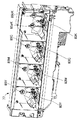
図4を参照して、各色の現像剤補給装置及び各色の現像剤収納容器の配置関係について説明する。図4は、各色の現像装置4Y,4M,4C,4Kと、現像装置にプレミックストナーを補給する現像剤補給装置70Y,70M,70C,70Kの全体構成を示す斜視図である。
現像剤補給装置70Y,70M,70C,70Kは、現像装置4Y,4M,4C,4Kの上部に配置されている。現像剤補給装置70は、プレミックストナーを収納した現像剤収納容器71と、後述するサブホッパ90(図14参照)とを有している。図4では、C色とK色の現像剤収納容器71C,71Kが装着されている状態を示し、Y色とM色の現像剤収納容器71Y,71Kは離脱されている状態を示している。現像剤収納容器71は、現像剤収納容器71を収容する現像剤収納容器収容部である容器保持部77(後述する図11等参照)に保持される。
With reference to FIG. 4, the arrangement relationship between the developer replenishing device for each color and the developer storage container for each color will be described. FIG. 4 is a perspective view showing the overall configuration of each color developing device 4Y, 4M, 4C, 4K and developer replenishing device 70Y, 70M, 70C, 70K for replenishing the developing device with premixed toner.
The developer supply devices 70Y, 70M, 70C, and 70K are disposed above the developing devices 4Y, 4M, 4C, and 4K. The developer supply device 70 includes a developer storage container 71 that stores premixed toner, and a sub hopper 90 (see FIG. 14) described later. FIG. 4 shows a state where C and K developer storage containers 71C and 71K are mounted, and shows a state where Y and M developer storage containers 71Y and 71K are detached. The developer storage container 71 is held in a container holding portion 77 (see FIG. 11 and the like described later) that is a developer storage container storage portion that stores the developer storage container 71.

容器保持部77は、4つに区画されており、図中左側から順に、Y色、M色、C色、K色(イエロー、マゼンタ、シアン、黒)の現像剤収納容器71が保持される。現像剤収納容器71は、容器保持部77に対して着脱可能、更には後述するように挿脱可能(差し込んだり外したりすることを意味する)に保持される。現像剤収納容器71内のプレミックトナーが無くなると、ユーザが容器保持部77から現像剤収納容器71を抜き出し、新品の現像剤収納容器71を容器保持部77に差し込む。これにより、新しいプレミックストナーが後述するサブホッパ90(図14参照)に供給される。   The container holding unit 77 is divided into four, and holds developer storage containers 71 of Y color, M color, C color, and K color (yellow, magenta, cyan, black) in order from the left side in the drawing. . The developer storage container 71 is held detachably with respect to the container holding portion 77 and is further detachable (meaning being inserted and removed) as will be described later. When the pre-mixed toner in the developer container 71 runs out, the user pulls out the developer container 71 from the container holder 77 and inserts a new developer container 71 into the container holder 77. As a result, new premix toner is supplied to a sub hopper 90 (see FIG. 14) described later.

現像剤補給装置70Y,70M,70C,70Kは、画像形成装置の前側、即ち図1の紙面手前側、図2に示す右側の前ドア58側に配置されており、ユーザは画像形成装置の前側から現像剤収納容器71にアクセス可能となっている。   The developer supply devices 70Y, 70M, 70C, and 70K are arranged on the front side of the image forming apparatus, that is, on the front side of the paper surface in FIG. 1, and on the right front door 58 side in FIG. The developer container 71 can be accessed.

図5、図6を参照して、K色用の現像剤収納容器及びY,M,C色の現像剤収納容器について説明する。図5は、K色用の現像剤収納容器71Kを裏側(画像形成装置への挿入方向下流側)から見た斜視図である。図6は、Y,M,C色の現像剤補給装置に用いられるカラー(Y,M,C)用(以下、単にカラー用と記載する)の現像剤収納容器71Y,71M,71Cを裏側(画像形成装置への挿入方向下流側)から見た斜視図である。図5、図6を始めとするX,Y,Z座標において、X方向は現像剤収納容器の幅(図1の左右)に対応する幅方向を、Y方向は現像剤収納容器の図1等の奥行きに対応する前後方向であり、Z方向は現像剤収納容器の高さに対応する上下方向である。   With reference to FIGS. 5 and 6, the developer storage container for K color and the developer storage containers for Y, M, and C colors will be described. FIG. 5 is a perspective view of the developer storage container 71K for K color as viewed from the back side (downstream in the insertion direction to the image forming apparatus). FIG. 6 shows the developer storage containers 71Y, 71M, 71C for color (Y, M, C) (hereinafter simply referred to as “color”) used in the Y, M, C developer supplying device. FIG. 3 is a perspective view seen from the downstream side in the insertion direction of the image forming apparatus. 5 and 6, the X direction is the width direction corresponding to the width of the developer container (left and right in FIG. 1), and the Y direction is FIG. 1 of the developer container. The Z direction is the vertical direction corresponding to the height of the developer container.

本実施形態においては、図5、図6に示すように、K色の現像剤収納容器71Kが、カラー用の現像剤収納容器71Y,71M,71Cよりも容積が大きくなっている。一般的なユーザは、フルカラー画像の出力よりも白黒画像の出力の方が多い。このため、トナーの消費スピードは、カラー用よりも黒用(K色用)の方が速くなる。よって、K色の現像剤収納容器71Kを、カラーの現像剤収納容器71Y,71M,71Cと同じ形状とした場合、K色の現像剤収納容器71が、頻繁に交換されてしまうことになり、ユーザの利便性が悪くなる。このようなことから、本実施形態では、K色用の現像剤収納容器71Kの容積を、カラー用の現像剤収納容器71Y,71M,71Cの容積よりも大きくして、カラー用の現像剤収納容器71Y,71M,71Cよりも多くのプレミックストナーを収納している。尚、図5に示されている現像剤収納容器71K用のカップリング74a,74b、図6に示されている現像剤収納容器71Y,71M,71C用のカップリング74については、後述する。   In the present embodiment, as shown in FIGS. 5 and 6, the K developer storage container 71K has a larger volume than the color developer storage containers 71Y, 71M, 71C. A typical user is more likely to output a black and white image than a full color image. For this reason, the toner consumption speed is faster for black (for K color) than for color. Therefore, when the K-color developer storage container 71K has the same shape as the color developer storage containers 71Y, 71M, 71C, the K-color developer storage container 71 is frequently replaced. User convenience deteriorates. For this reason, in this embodiment, the volume of the developer storage container 71K for K color is made larger than the volume of the developer storage containers 71Y, 71M, 71C for color, and the developer storage for color is stored. More premixed toner is stored than the containers 71Y, 71M, 71C. The couplings 74a and 74b for the developer storage container 71K shown in FIG. 5 and the couplings 74 for the developer storage containers 71Y, 71M and 71C shown in FIG. 6 will be described later.

図7、図8を参照して、カラー用の現像剤収納容器71Y,71M,71Cの基本的な内部構成を説明する。図7は、カラー用の現像剤収納容器71Y,71M,71Cの簡略的な断面図、図8は、カラー用の現像剤収納容器71Y,71M,71Cの断面斜視図である。
図7、図8に示すように、カラー用の現像剤収納容器71Y,71M,71Cは、現像剤収納部としての容器本体71Aと、容器本体71A内に配設される供給部材としての搬送スクリュ72と、攪拌部材としてのアジテータ73とを備えている。アジテータ73は、容器本体71A内で搬送スクリュ72と平行に配設されている。
With reference to FIGS. 7 and 8, the basic internal structure of the developer storage containers 71Y, 71M, 71C for color will be described. FIG. 7 is a simplified cross-sectional view of color developer storage containers 71Y, 71M, 71C, and FIG. 8 is a cross-sectional perspective view of color developer storage containers 71Y, 71M, 71C.
As shown in FIGS. 7 and 8, the developer storage containers 71Y, 71M, and 71C for color include a container body 71A as a developer storage section and a transport screw as a supply member disposed in the container body 71A. 72 and an agitator 73 as a stirring member. The agitator 73 is disposed in parallel with the transport screw 72 in the container main body 71A.

アジテータ73は、軸部731と、軸部731と一体で成型された接続部としての骨部734と、骨部734に取り付けられた羽根部732とを備えている。羽根部732は、骨部734を介して軸部731に支持されている。アジテータ73は、後述する現像剤供給駆動部80(図12等参照)によって駆動され、搬送スクリュ72と平行に配設された軸部731と一体で、図6及び図7に破線で示す矢印NR方向(正転方向)に回転する。そして、アジテータ73は、容器本体71A内に収容されている現像剤Gであるプレミックストナー(キャリアCとトナーTとを含む)を攪拌しながら搬送スクリュ72に向けて移動させるように搬送する。また、アジテータ73の軸部731と骨部734とは剛性を有する剛体として形成されている。また、アジテータ73の羽根部732は可撓性を有しているため、羽根部732が容器本体71Aの内壁71bと接触することにより羽根部732が撓みながら、アジテータ73が回転する。搬送スクリュ72は、アジテータ73により搬送されてきたプレミックストナーを後述する図14のサブホッパ90へと搬送する。   The agitator 73 includes a shaft portion 731, a bone portion 734 as a connection portion molded integrally with the shaft portion 731, and a blade portion 732 attached to the bone portion 734. The blade portion 732 is supported by the shaft portion 731 via the bone portion 734. The agitator 73 is driven by a developer supply driving unit 80 (see FIG. 12 and the like) described later, and is integrated with a shaft portion 731 disposed in parallel with the conveying screw 72, and is indicated by an arrow NR indicated by a broken line in FIGS. Rotate in the direction (forward direction). The agitator 73 conveys the premix toner (including the carrier C and the toner T), which is the developer G accommodated in the container main body 71A, while moving it toward the conveyance screw 72 while stirring. The shaft portion 731 and the bone portion 734 of the agitator 73 are formed as rigid bodies having rigidity. Further, since the blade portion 732 of the agitator 73 has flexibility, the agitator 73 rotates while the blade portion 732 is bent by the blade portion 732 coming into contact with the inner wall 71b of the container main body 71A. The conveying screw 72 conveys the premixed toner conveyed by the agitator 73 to the sub hopper 90 of FIG.

アジテータ73の剛体である軸部731及び骨部734は、金属や樹脂などで一体的に形成するのが簡便で好ましいが、他の材料あるいは製造方法であってもよい。また、可撓性を有する羽根部732は、剛性の低い材質で製造することが望ましい。例えば、羽根部732は、PET(ポリエチレンテレフタレート)、PE(ポリエチレン)、PP(ポリプロピレン)、PPS(ポリフェニレンサルファイド)又はポリウレタンなどから成るシート状の可撓性を有する材質が望ましい。この羽根部732の厚さは、約50[μm]〜500[μm]程度が好ましく、より好ましくは100[μm]〜300[μm]が好適である。尚、アジテータ73は、上述したように軸部731及び骨部734と、羽根部732とを別部材で構成しているが、これに限らず、樹脂材料を用いて射出成型機により一体成型してもよい。   The shaft portion 731 and the bone portion 734, which are rigid bodies of the agitator 73, are simply and preferably integrally formed of metal, resin, or the like, but other materials or manufacturing methods may be used. In addition, the flexible blade portion 732 is preferably manufactured from a material having low rigidity. For example, the blade portion 732 is preferably a sheet-like flexible material made of PET (polyethylene terephthalate), PE (polyethylene), PP (polypropylene), PPS (polyphenylene sulfide), polyurethane, or the like. The thickness of the blade portion 732 is preferably about 50 [μm] to 500 [μm], more preferably 100 [μm] to 300 [μm]. As described above, the agitator 73 includes the shaft portion 731, the bone portion 734, and the blade portion 732 as separate members. However, the agitator 73 is not limited thereto, and is integrally molded by an injection molding machine using a resin material. May be.

図6に示すように、カラー用の現像剤収納容器71Y,71M,71Cのアジテータ73の軸部731の一端部は、容器本体71Aから露出しており、この一端部に攪拌部材用の一方のカップリング手段であり、容器側カップリング部材であるカップリング74が設けられている。カップリング74は、軸部731の一端部から突出する爪形状をなす一対の部材であり、図11、図12に示す容器保持部77に装着されたときに画像形成装置本体側の本体側カップリング部材である駆動側のカップリング85Y,85M,85Cと接触し噛み合うようになっている。尚、カップリングはジョイントとも呼ばれる。   As shown in FIG. 6, one end portion of the shaft portion 731 of the agitator 73 of the color developer storage containers 71Y, 71M, 71C is exposed from the container main body 71A. A coupling 74 which is a coupling means and is a container side coupling member is provided. The coupling 74 is a pair of claw-shaped members protruding from one end of the shaft portion 731, and the main body side cup on the image forming apparatus main body side when mounted on the container holding portion 77 shown in FIGS. 11 and 12. The drive-side couplings 85Y, 85M, and 85C, which are ring members, come into contact with and mesh with each other. The coupling is also called a joint.

カラー用の現像剤収納容器71Y,71M,71Cのスクリュ72の軸部721の一端部は、容器本体71Aから露出しており、この一端部に搬送部材用のジョイント76が設けられている。ジョイント76は、軸部721の一端部から突出する爪形状をなす一対の部材であり、図11、図12に示す容器保持部77に装着されたときに画像形成装置本体側の搬送用ジョイント83Y,83M,83Cと接触し噛み合うようになっている。   One end portion of the shaft portion 721 of the screw 72 of the color developer storage containers 71Y, 71M, 71C is exposed from the container body 71A, and a transport member joint 76 is provided at this one end portion. The joint 76 is a pair of claw-shaped members protruding from one end of the shaft portion 721. When the joint 76 is attached to the container holding portion 77 shown in FIGS. 11 and 12, the conveyance joint 83Y on the image forming apparatus main body side. , 83M, 83C to come into contact with each other.

図9は、K色用の現像剤収納容器71Kの断面斜視図である。K色用の現像剤収納容器71Kの容器本体71A内には、第1アジテータ73aと、第2アジテータ73bと、搬送スクリュ72とが配設されている。第1アジテータ73a、第2アジテータ73bは、先に図7及び図8に示したカラー用の現像剤収納容器71Y,71M,71C内に設けられたアジテータ73と同様の構成である。   FIG. 9 is a cross-sectional perspective view of a developer storage container 71K for K color. A first agitator 73a, a second agitator 73b, and a transport screw 72 are disposed in the container main body 71A of the developer storage container 71K for K color. The first agitator 73a and the second agitator 73b have the same configuration as the agitator 73 provided in the color developer storage containers 71Y, 71M, 71C previously shown in FIGS.

図10は、K用の現像剤収納容器71Kのカップリング74a,74b取り付け部周辺を示す拡大図である。図5及び図10に示すように、K用の現像剤収納容器71Kの第1、第2アジテータ73a,73bの軸部731a,731bの一端部は、容器本体71Aから露出しており、この一端部に攪拌部材用の被駆動側のカップリング手段である容器側カップリング部材を構成するカップリング74a,74bが設けられている。現像剤収納容器71Kのカップリング74a,74bは、現像剤収納容器71Y,71M,71Cのカップリング74と同様の構成である。カップリング74a,74bは、図11、図12に示す容器保持部77に装着されたときに画像形成装置本体側の駆動側のカップリング85aK,85bKと接触し噛み合うようになっている。   FIG. 10 is an enlarged view showing the vicinity of the coupling 74a, 74b attachment portion of the K developer storage container 71K. As shown in FIGS. 5 and 10, one end portions of the shaft portions 731a and 731b of the first and second agitators 73a and 73b of the developer storage container 71K for K are exposed from the container body 71A. Couplings 74a and 74b constituting a container side coupling member, which is a driven side coupling means for the agitating member, are provided in the part. The couplings 74a and 74b of the developer storage container 71K have the same configuration as the couplings 74 of the developer storage containers 71Y, 71M, and 71C. The couplings 74a and 74b come into contact with and mesh with the drive-side couplings 85aK and 85bK on the image forming apparatus main body side when mounted on the container holding portion 77 shown in FIGS.

図5に示すように、K用の現像剤収納容器71Kのスクリュ72の軸部721の一端部は、容器本体71Aから露出しており、この一端部に搬送部材用のジョイント76が設けられている。ジョイント76は、カラー用の現像剤収納容器71Y,71M,71Cのジョイント76と同様の構成であり、図11、図12に示す容器保持部77に装着されたときに画像形成装置本体側の搬送用ジョイント83Kと接触し噛み合うようになっている。   As shown in FIG. 5, one end portion of the shaft portion 721 of the screw 72 of the developer storage container 71K for K is exposed from the container main body 71A, and a transport member joint 76 is provided at this one end portion. Yes. The joint 76 has the same configuration as the joint 76 of the color developer storage containers 71Y, 71M, 71C, and is transported on the image forming apparatus main body side when mounted on the container holding portion 77 shown in FIGS. It comes into contact with and meshes with the joint 83K.

図11及び図12を参照して、現像剤収納容器71Y,71M,71Cの収容部である容器保持部77及び現像剤供給駆動部80Y,80M,80C,80Kについて説明する。図11は、現像剤収納容器71Y,71M,71C,71Kの収容部である容器保持部77を示す斜視図であり、図12(a)は、現像剤供給駆動部80Y,80M,80C,80Kを示す斜視図である。図12(b)は、現像剤供給駆動部80Yを代表して示す拡大斜視図である。
図11及び図12に示すように、容器保持部77及びカラー用の現像剤供給駆動部80Y,80M,80Cには、上述したカップリング74に接続される駆動側のカップリング85Y,85M,85Cが設けられている。K色の現像剤供給駆動部80Kには、第1アジテータの軸部731aに取り付けられたカップリング74aに接続される第1駆動側のカップリング85aKが設けられている。また、第2アジテータの軸部731bに取り付けられたカップリング74bに接続される第2駆動側のカップリング85bKも設けられている。
With reference to FIGS. 11 and 12, the container holding portion 77 and the developer supply driving portions 80Y, 80M, 80C, and 80K, which are the storage portions for the developer storage containers 71Y, 71M, and 71C, will be described. FIG. 11 is a perspective view showing a container holding portion 77 that is a storage portion for the developer storage containers 71Y, 71M, 71C, 71K, and FIG. 12A is a developer supply drive section 80Y, 80M, 80C, 80K. FIG. FIG. 12B is an enlarged perspective view representatively showing the developer supply driving unit 80Y.
As shown in FIGS. 11 and 12, the container holding unit 77 and the color developer supply driving units 80Y, 80M, and 80C include driving-side couplings 85Y, 85M, and 85C connected to the coupling 74 described above. Is provided. The K-color developer supply drive unit 80K is provided with a first drive side coupling 85aK connected to a coupling 74a attached to the shaft portion 731a of the first agitator. Further, a second drive side coupling 85bK connected to a coupling 74b attached to the shaft portion 731b of the second agitator is also provided.

また、容器保持部77及び各現像剤供給駆動部80Y,80M,80C,80Kには、現像剤収納容器71Y,71M,71C,71Kの搬送スクリュ72に接続する搬送用ジョイント83Y,83M,83C,83Kが設けられている。また、容器保持部77及び各現像剤供給駆動部80Y,80M,80C,80Kには、各現像剤収納容器71Y,71M,71C,71Kが着脱可能(挿脱可能)にするための各種位置決めや案内部材なども配設されている。   Further, the container holding unit 77 and the developer supply driving units 80Y, 80M, 80C, and 80K include conveyance joints 83Y, 83M, and 83C that are connected to the conveyance screws 72 of the developer storage containers 71Y, 71M, 71C, and 71K. 83K is provided. Further, the container holding unit 77 and the developer supply driving units 80Y, 80M, 80C, and 80K are provided with various positionings for making the developer storage containers 71Y, 71M, 71C, and 71K detachable (removable). Guide members and the like are also disposed.

現像剤供給駆動部80Y,80M,80C,80Kは、現像剤収納容器71Y,71M,71C,71K内の現像剤Gであるプレミックストナーを、図12に示す現像剤補給装置のサブホッパ90Y,90M,90C,90Kに供給するときに用いる駆動部である。現像剤供給駆動部80Y,80M,80Cは、カラー用の現像剤収納容器71Y,71M,71Cのアジテータ73、搬送スクリュ72、及び後述するサブホッパ90Y,90M,90Cの第1、第2攪拌搬送部材96,97(図15参照)を駆動させるものである。現像剤供給駆動部80Kは、K用の現像剤収納容器71Kの第1アジテータ73a、第2アジテータ73b、搬送スクリュ72、及び後述するサブホッパ90Kの第1、第2攪拌搬送部材96,97(図15参照)を駆動させるものである。   The developer supply drive units 80Y, 80M, 80C, and 80K apply premixed toner, which is the developer G in the developer containers 71Y, 71M, 71C, and 71K, to the sub-hoppers 90Y and 90M of the developer supply device shown in FIG. , 90C, 90K. The developer supply driving units 80Y, 80M, and 80C include color developer storage containers 71Y, 71M, and 71C agitators 73, a transport screw 72, and first and second agitation transport members of sub hoppers 90Y, 90M, and 90C, which will be described later. 96 and 97 (see FIG. 15) are driven. The developer supply drive unit 80K includes a first agitator 73a and a second agitator 73b of the K developer storage container 71K, a transport screw 72, and first and second agitating and transporting members 96 and 97 of a sub hopper 90K described later (see FIG. 15) is driven.

図12に示すように、各現像剤供給駆動部80Y,80M,80C,80Kは、駆動源としての供給用駆動モータ81Y,81M,81C,81Kを備えている。供給用駆動モータ81Y,81M,81C,81Kは、本実施形態では直流電動機である正逆回転可能なDCモータを採用している。各現像剤供給駆動部80Y,80M,80C,80Kは、複数のギヤからなるギヤ列を有している。このギヤ列を構成するギヤは、図12に示す面板86Y,86M,86C,86Kに回動(正逆方向に円運動することを意味する)自在に支持されている。   As shown in FIG. 12, each of the developer supply drive units 80Y, 80M, 80C, 80K includes supply drive motors 81Y, 81M, 81C, 81K as drive sources. In the present embodiment, the supply drive motors 81Y, 81M, 81C, and 81K employ DC motors that can rotate in the forward and reverse directions, which are DC motors. Each developer supply drive unit 80Y, 80M, 80C, 80K has a gear train composed of a plurality of gears. The gears constituting this gear train are supported by face plates 86Y, 86M, 86C, 86K shown in FIG. 12 so as to be freely rotatable (meaning circular movement in forward and reverse directions).

図12(b)を用いて、各供給用駆動モータ81Y,81M,81Cの駆動力をカラー用の現像剤収納容器71Y,71M,71Cの搬送スクリュ、アジテータに伝達する機構を、現像剤供給駆動部80Yを代表して説明すると次のとおりである。尚、現像剤収納容器71Y,71M,71C,71Kは、図11に示す容器保持部77に装着セットされているものとする。この際、駆動側のカップリング85Yと現像剤収納容器71Yのカップリング74とが、図13に示すように係合(係わり合うことを意味する)し、駆動力を伝達可能な噛み合い可能な状態にある。
供給用駆動モータ81Yの駆動力は、その出力軸に固定されたウォーム103aから、ウォーム103aと噛み合うウォームホイール103b、ウォームホイール103と噛み合うスクリュ駆動ギヤ104を介して搬送用ジョイント83Yに伝達される。これにより、図6及び図7等に示す搬送スクリュ72が回転駆動される。スクリュ駆動ギヤ104は、搬送用ジョイント83Yの同軸上に設けられている。
Using FIG. 12B, a mechanism for transmitting the driving force of each of the supply drive motors 81Y, 81M, 81C to the conveying screws and agitators of the color developer storage containers 71Y, 71M, 71C is provided as a developer supply drive. The section 80Y will be described as a representative as follows. It is assumed that the developer storage containers 71Y, 71M, 71C, 71K are mounted and set on the container holding portion 77 shown in FIG. At this time, the coupling 85Y on the driving side and the coupling 74 of the developer storage container 71Y are engaged (meaning that they are engaged) as shown in FIG. It is in.
The driving force of the supply drive motor 81Y is transmitted from the worm 103a fixed to the output shaft to the transfer joint 83Y via the worm wheel 103b meshed with the worm 103a and the screw drive gear 104 meshed with the worm wheel 103. As a result, the conveying screw 72 shown in FIGS. 6 and 7 is rotated. The screw drive gear 104 is provided on the same axis as the transfer joint 83Y.

更に、上記駆動力は、スクリュ駆動ギヤ104と噛み合う大径ギヤ105aと同軸に設けられた小径ギヤ105bとからなる第1ギヤ105へと伝達される。更に、上記駆動力は、第1ギヤ105の小径ギヤ105bと噛み合う大径ギヤ106aと同軸に設けられた小径ギヤ106bとからなる第2ギヤ106、第2ギヤ106の小径ギヤ106bと噛み合うアジテータ駆動ギヤ84と同軸上に設けられている駆動側のカップリング85Yへと伝達される。これにより、駆動側のカップリング85Yと現像剤収納容器71Yのカップリング74とが、共に矢印NR方向(正転方向)に回転することで、アジテータ73も同方向に回転駆動されて現像剤を攪拌する動作を行うこととなる。   Further, the driving force is transmitted to a first gear 105 including a large-diameter gear 105 a meshing with the screw driving gear 104 and a small-diameter gear 105 b provided coaxially. Further, the driving force is driven by an agitator that meshes with a second gear 106 comprising a large-diameter gear 106a meshed with the small-diameter gear 105b of the first gear 105 and a small-diameter gear 106b provided coaxially with the small-diameter gear 106b of the second gear 106. This is transmitted to the drive-side coupling 85Y provided coaxially with the gear 84. As a result, the drive-side coupling 85Y and the coupling 74 of the developer container 71Y both rotate in the direction of the arrow NR (forward rotation direction), so that the agitator 73 is also driven to rotate in the same direction. The operation of stirring is performed.

供給用駆動モータ81Yが図6及び図7等に示すカップリング74を矢印NR方向(正転方向)に回転させる際の回転方向を、「現像剤を攪拌すべく回転していた方向」と定義する(供給用駆動モータ81M,81Cも同じ)。   The rotation direction when the supply drive motor 81Y rotates the coupling 74 shown in FIGS. 6 and 7 in the direction of the arrow NR (forward rotation direction) is defined as “the direction in which the developer was rotated to stir the developer”. (The same applies to the drive motors 81M and 81C for supply).

図12(a)を用いて、供給用駆動モータ81Kの駆動力を現像剤収納容器71Kの搬送スクリュ、アジテータに伝達する機構を、現像剤供給駆動部80Yと相違する点を中心に説明すると、次のとおりである。この際、図13に示すように、第1駆動側のカップリング85aKと現像剤収納容器71Kの第1のカップリング74aとが、第2駆動側のカップリング85bKと現像剤収納容器71Kの第2のカップリング74bとが係合し、駆動力を伝達可能な噛み合い可能な状態にある。供給用駆動モータ81Kの駆動力は、現像剤供給駆動部80Yと同様のギヤ列を介して搬送用ジョイント83Kに伝達される。これにより、図5及び図9等に示す搬送スクリュ72が回転駆動される。   A mechanism for transmitting the driving force of the supply drive motor 81K to the conveying screw and agitator of the developer storage container 71K will be described with reference to FIG. 12A, focusing on differences from the developer supply drive unit 80Y. It is as follows. At this time, as shown in FIG. 13, the first drive side coupling 85aK and the first coupling 74a of the developer storage container 71K are connected to the second drive side coupling 85bK and the developer storage container 71K. The two couplings 74b are engaged with each other and are in a meshable state capable of transmitting a driving force. The driving force of the supply drive motor 81K is transmitted to the conveyance joint 83K through the same gear train as the developer supply drive unit 80Y. As a result, the conveying screw 72 shown in FIGS. 5 and 9 is rotated.

更に、上記駆動力は、現像剤供給駆動部80Yと同様のギヤ列を介して、第1アジテータ駆動ギヤ84aKと同軸上に設けられた第1駆動側のカップリング85aKへと伝達される。同時に第1アジテータ駆動ギヤ84aKと噛み合う第2アジテータ駆動ギヤ84bKに供給用駆動モータ81Kの駆動力が伝達されると共に、第2アジテータ駆動ギヤ84bKと同軸上設けられた第2駆動側のカップリング85bKに駆動力が伝達される。これにより、第1駆動側のカップリング85aKと現像剤収納容器71Kの第1カップリング74aとが、共に矢印NR方向(正転方向)に回転する。同時に、第2駆動側のカップリング85bKと現像剤収納容器71Kの第2カップリング74bとが、矢印NR方向と逆方向の矢印RR方向(逆転方向)に回転する。これにより、第1アジテータ73aが矢印NR方向(正転方向)に回転駆動されると同時に、第2アジテータ73bが矢印RR方向(逆転方向)に回転駆動されることにより、現像剤が現像剤収納容器71内中央に向けて掻き混ぜられる攪拌動作が行われることとなる。   Further, the driving force is transmitted to the first driving side coupling 85aK provided coaxially with the first agitator driving gear 84aK through the same gear train as the developer supply driving unit 80Y. At the same time, the driving force of the supply drive motor 81K is transmitted to the second agitator drive gear 84bK meshing with the first agitator drive gear 84aK, and the second drive side coupling 85bK provided coaxially with the second agitator drive gear 84bK. The driving force is transmitted to. As a result, the coupling 85aK on the first drive side and the first coupling 74a of the developer container 71K both rotate in the arrow NR direction (forward rotation direction). At the same time, the coupling 85bK on the second drive side and the second coupling 74b of the developer container 71K rotate in the arrow RR direction (reverse direction) opposite to the arrow NR direction. As a result, the first agitator 73a is rotationally driven in the arrow NR direction (forward rotation direction), and at the same time, the second agitator 73b is rotationally driven in the arrow RR direction (reverse rotation direction), whereby the developer is stored in the developer. An agitation operation that is stirred toward the center of the container 71 is performed.

供給用駆動モータ81Kが図5等に示す第1のカップリング74aを矢印NR方向(正転方向)に、且つ第2のカップリング74bを矢印RR方向(逆転方向)に回転させる際の回転方向を、「現像剤を攪拌すべく回転していた方向」と定義する。   Rotation direction when the supply drive motor 81K rotates the first coupling 74a shown in FIG. 5 and the like in the arrow NR direction (forward rotation direction) and the second coupling 74b in the arrow RR direction (reverse rotation direction). Is defined as “the direction in which the developer was rotated to stir”.

ここで、上述した背景技術内容を補説する。上記アジテータのような攪拌部材を有した現像剤収納容器において、現像剤が充填された現像剤収納容器を貨物自動車で運搬する際には、運搬時の微振動と重力により容器内部のトナーが圧縮されて嵩が小さくなり、嵩密度が著しく上昇するという現象が発生する。この現象が起こった現像剤収納容器では、トナーの流動性が悪くなり、攪拌部材の回転トルクが増大し、攪拌部材に大きな負荷が発生する。この際、攪拌部材の回転トルクおよび負荷は、いかなる場合においても、攪拌部材の破壊強度以下で、且つ、駆動モータの停動トルク以下であることが理想である。   Here, the background art content mentioned above is supplemented. In a developer storage container having a stirring member such as the agitator, when the developer storage container filled with the developer is transported by a lorry, the toner inside the container is compressed by the slight vibration and gravity during transport. Thus, the phenomenon that the bulk is reduced and the bulk density is significantly increased occurs. In the developer storage container in which this phenomenon occurs, the fluidity of the toner deteriorates, the rotational torque of the stirring member increases, and a large load is generated on the stirring member. At this time, it is ideal that the rotational torque and the load of the stirring member are, in any case, not more than the breaking strength of the stirring member and not more than the stopping torque of the drive motor.

近年、省エネの観点から上記したようなトナー定着温度の低温化が進められており、このような低温定着トナーを用いた際に、攪拌部材に掛かる負荷を攪拌部材の破壊強度以下にできない場合がある。このような場合、攪拌部材の破損を防止するために、攪拌部材を回転駆動する駆動モータの停動トルクを攪拌部材の破壊トルク以下とし、攪拌部材の回転トルクが著しく増大した場合にはモータロックとなるようにして、攪拌部材が破損する前に停止させることが必要となる。駆動モータがロックした場合には、DCモータの場合、通常より大きい停動電流が流れるため、駆動モータの電流値を常にモニタリングすることでモータロック検知が可能である。   In recent years, the toner fixing temperature has been lowered as described above from the viewpoint of energy saving. When such a low-temperature fixing toner is used, the load applied to the stirring member may not be less than the breaking strength of the stirring member. is there. In such a case, in order to prevent breakage of the stirring member, the stopping torque of the drive motor that rotationally drives the stirring member is set to be equal to or lower than the breaking torque of the stirring member, and the motor lock is applied when the rotational torque of the stirring member increases significantly. Thus, it is necessary to stop the stirring member before it breaks. When the drive motor is locked, since a stationary current larger than normal flows in the case of a DC motor, the motor lock can be detected by constantly monitoring the current value of the drive motor.

しかしながら、画像形成装置及び現像剤収納容器には、画像形成装置本体に設置されている駆動モータの駆動力を、現像剤収納容器側の攪拌部材に伝達するために、双方にカップリング手段やカップリング部材又は駆動ジョイントを有している。モータロックが発生した際には、カップリング部材であるカップリングにかかる力が著しく増大するため、カップリング同士の摺動力が増し、その結果現像剤収納容器の引き抜き力が増大する。これにより、モータロックが発生し、ロックを解消するために現像剤収納容器を引き抜こうとしても、カップリング同士(容器側カップリング部材の爪と、本体側カップリング部材の爪)が押し付けられているので現像剤収納容器を引き抜くことが困難になってしまう。   However, the image forming apparatus and the developer container have both a coupling means and a cup in order to transmit the driving force of the drive motor installed in the image forming apparatus body to the stirring member on the developer container. It has a ring member or drive joint. When the motor lock occurs, the force applied to the coupling which is the coupling member is remarkably increased, so that the sliding force between the couplings is increased, and as a result, the pulling force of the developer container is increased. As a result, a motor lock is generated, and even when an attempt is made to pull out the developer storage container to release the lock, the couplings (the claws of the container side coupling member and the claws of the main body side coupling member) are pressed against each other. Therefore, it becomes difficult to pull out the developer container.

本発明の実施形態では、上記目的を達成するための特有の手段を上述したように備えている。そこで、図13を参照して、上記目的を達成するための手段の具体的構成例を簡潔に説明する。図13に示すように、現像剤を攪拌すべく共に矢印NR方向(正転方向)に回転していた駆動側のカップリング85Yと現像剤収納容器71Yのカップリング74とは、現像剤収納容器71Y内のアジテータ73に掛かる回転トルクが著しく増大する場合がある。このような場合には、上述したように供給用駆動モータ81Yがモータロックとなるようにして、アジテータ73が破損する前に供給用駆動モータ81Yを停止させる制御を行う。駆動側のカップリング85Yには、一対の爪状部材85cが一体的に設けられている。同様に、現像剤収納容器71Yのカップリング74(以下、被駆動側のカップリング74ともいう)には、一対の爪状部材74cが駆動側のカップリング85Yの一対の爪状部材85cと選択的に接触し噛み合うように、被駆動側のカップリング74に一体的に設けられている。爪状部材85cと爪状部材74cとが噛み合う回動方向には、一般的に、最初に係合するための比較的大きな適度の遊びが予め設けられている。   In the embodiment of the present invention, the specific means for achieving the above object is provided as described above. Therefore, with reference to FIG. 13, a specific configuration example of means for achieving the above object will be briefly described. As shown in FIG. 13, the driving-side coupling 85Y and the coupling 74 of the developer storage container 71Y that have been rotated in the direction of the arrow NR (forward rotation direction) together with stirring of the developer are the developer storage container. The rotational torque applied to the agitator 73 in 71Y may increase remarkably. In such a case, as described above, the supply drive motor 81Y is locked so that the supply drive motor 81Y is stopped before the agitator 73 is damaged. A pair of claw-like members 85c are integrally provided on the driving-side coupling 85Y. Similarly, for the coupling 74 of the developer container 71Y (hereinafter also referred to as the driven-side coupling 74), the pair of claw-shaped members 74c is selected from the pair of claw-shaped members 85c of the driving-side coupling 85Y. Are integrally provided on the coupling 74 on the driven side so as to contact and mesh with each other. In the rotational direction in which the claw-like member 85c and the claw-like member 74c are engaged, generally, a relatively large appropriate play for first engaging is provided in advance.

供給用駆動モータ81Yがモータロックと判断されて停止した際、現像剤を攪拌すべく矢印NR方向に回転していた駆動側のカップリング85Yの爪状部材85cと、被駆動側のカップリング74の爪状部材74cとの噛み合い部分には、大きな負荷が掛かっている。そこで、供給用駆動モータ81Yがモータロックと判断されて停止した際に、一定時間だけ供給用駆動モータ81Yを、現像剤を攪拌すべく回転していた矢印NR方向と逆の矢印RR方向に逆転駆動動作させる。また、逆転駆動動作させた後、そのまま停止させる。これにより、駆動側のカップリング85Yの爪状部材85cと被駆動側のカップリング74の爪状部材74cとの噛み合い部分の力が開放される。従って、矢印RR方向と直交する現像剤収納容器71Yの引き抜き方向に働く「引き抜き力」が増大することなく、現像剤収納容器71Yを駆動側のカップリング85Y側から容易に引き抜くことができるようになる。   When the supply driving motor 81Y is determined to be motor-locked and stopped, the claw-like member 85c of the driving-side coupling 85Y that has been rotated in the direction of the arrow NR to stir the developer, and the driven-side coupling 74 A large load is applied to the portion engaged with the claw-like member 74c. Therefore, when the supply drive motor 81Y is determined to be locked and stopped, the supply drive motor 81Y is reversed in the direction of the arrow RR opposite to the direction of the arrow NR that has been rotated to stir the developer. Drive operation. Further, after the reverse drive operation is performed, the operation is stopped as it is. As a result, the force at the meshing portion between the claw-like member 85c of the driving-side coupling 85Y and the claw-like member 74c of the driven-side coupling 74 is released. Therefore, the developer container 71Y can be easily pulled out from the coupling 85Y side on the driving side without increasing the “pulling force” acting in the pulling direction of the developer container 71Y perpendicular to the arrow RR direction. Become.

尚、図中括弧を付して示すように、現像剤を攪拌すべく矢印RR方向に回転していた第2駆動側のカップリング85bKの爪状部材85cと、被駆動側の第2カップリング74の爪状部材74cとの接触・噛み合い状態においても、上述したと同様である。上述したと同様の作用を考慮して、逆の矢印NR方向(図中破線で示す)に逆転駆動動作させる。一定時間だけ供給用駆動モータ81Kを、現像剤を攪拌すべく回転していた矢印RR方向と逆の矢印NR方向(図中破線で示す)に逆転駆動動作させればよい。   As shown in parentheses in the figure, the claw-like member 85c of the second drive side coupling 85bK that has been rotated in the direction of the arrow RR to stir the developer, and the second coupling on the driven side. Also in the state of contact / engagement with the claw-like member 74c of 74, it is the same as described above. Considering the same effect as described above, the reverse drive operation is performed in the reverse arrow NR direction (indicated by a broken line in the figure). The supply drive motor 81K may be reversely driven in the direction of the arrow NR (indicated by the broken line in the figure) opposite to the direction of the arrow RR that has been rotated to stir the developer for a fixed time.

各供給用駆動モータ81Y,81M,81C,81Kの駆動力は、後述する第1攪拌搬送部材96(図15参照)の回転軸の後側端部に取り付けられた供給側ワンウェイクラッチ82に伝達される。そして、供給側ワンウェイクラッチ82を介して、後述する第1攪拌搬送部材96及び第2攪拌搬送部材97に各供給用駆動モータ81Y,81M,81C,81Kの駆動力が伝達される。   The driving force of each of the supply drive motors 81Y, 81M, 81C, 81K is transmitted to a supply-side one-way clutch 82 attached to a rear end portion of a rotary shaft of a first agitating and conveying member 96 (see FIG. 15) described later. The Then, the driving force of each of the supply drive motors 81Y, 81M, 81C, 81K is transmitted to the first stirring / conveying member 96 and the second stirring / conveying member 97, which will be described later, via the supply-side one-way clutch 82.

図14、図15を参照して、現像剤補給装置70Y,70M,70C,70Kのサブホッパ90Y,90M,90C,90Kについて説明する。尚、各色のサブホッパ90Y,90M,90C,90Kは、同一であるので、ここでは、K色のサブホッパについて説明するとともに、以下の説明では、Y,M,C,Kという添字を適宜省略して説明する。図14は、サブホッパ90の構成を示す斜視図、図15は、サブホッパ90の内部構造を示す斜視図である。図14、図15、図16において、矢印F方向は画像形成装置の前側を、矢印R方向は画像形成装置の後側を、それぞれ示している。   The sub hoppers 90Y, 90M, 90C, and 90K of the developer supply devices 70Y, 70M, 70C, and 70K will be described with reference to FIGS. Since the sub-hoppers 90Y, 90M, 90C, and 90K for each color are the same, the K-color sub-hopper will be described here, and the subscripts Y, M, C, and K are omitted as appropriate in the following description. explain. 14 is a perspective view showing the configuration of the sub hopper 90, and FIG. 15 is a perspective view showing the internal structure of the sub hopper 90. As shown in FIG. 14, 15, and 16, the arrow F direction indicates the front side of the image forming apparatus, and the arrow R direction indicates the rear side of the image forming apparatus.

図14、図15に示すように、サブホッパ90は、第1攪拌搬送部材96、第2攪拌搬送部材97、第1搬送部材98及び第2搬送部材99を収納し上部が開口したケース93bと、ケース93bの開口部を塞ぐ上カバー93aを有している。上カバー93aには、現像剤収納容器71の供給口から供給されるプレミックストナーを受け入れる受入口91が形成されている。   As shown in FIGS. 14 and 15, the sub hopper 90 includes a case 93 b that houses the first agitating and conveying member 96, the second agitating and conveying member 97, the first conveying member 98, and the second conveying member 99, and has an upper opening. An upper cover 93a is provided to close the opening of the case 93b. The upper cover 93 a is formed with a receiving port 91 that receives premix toner supplied from the supply port of the developer container 71.

本実施形態においては、現像装置4の真上にサブホッパ90が設けられており、各色のサブホッパ90の大きさは、同じである。一方、先の図5、図6を用いて説明したように、サブホッパ90の真上に配置される現像剤収納容器71は、各色同じではなく、K色の現像収納容器71Kが、カラー用の現像剤収納容器71Y,71M,71Cよりも大きい構成となっている。このため、装置のレイアウトの関係上、図12に示すように、現像剤収納容器71のプレミックストナーを現像剤貯留部90aに供給するための供給口72aY,72aM,72aC,72aKの位置が異なる。本実施形態では、供給口72aとサブホッパの現像剤検知センサ95が設けられた壁面からの距離が、K色は、4mm程、C色は、13mm程、M色は、23mm程、Y色は、33mm程となっている。   In the present embodiment, a sub hopper 90 is provided directly above the developing device 4, and the sizes of the sub hoppers 90 for the respective colors are the same. On the other hand, as described above with reference to FIGS. 5 and 6, the developer storage container 71 disposed immediately above the sub hopper 90 is not the same for each color, and the K-color development storage container 71K is used for color. It is larger than the developer storage containers 71Y, 71M, 71C. For this reason, the positions of the supply ports 72aY, 72aM, 72aC, and 72aK for supplying the premix toner in the developer container 71 to the developer reservoir 90a are different from each other in terms of the layout of the apparatus, as shown in FIG. . In the present embodiment, the distance from the supply port 72a and the wall surface on which the sub-hopper developer detection sensor 95 is provided is about 4 mm for K color, about 13 mm for C color, about 23 mm for M color, and about 23 mm for Y color. 33 mm.

サブホッパ90の受入口91を、各現像剤収納容器71の供給口72aY,72aM,72aC,72aKの位置を合わせて設ける場合、上カバー93aを、色毎に設ける必要があり、部品点数が増加し、装置のコストアップに繋がる。このため、本実施形態では、上カバー93aの受入口91を、現像剤収納容器71の並び方向に延びる長方形状にしている。これにより、サブホッパ90と現像剤収納容器71の供給口72aY,72aM,72aC,72aKとの位置関係が、現像剤収納容器71の並び方向で、色毎に互いに異なっても、共通の上カバーで対応することができる。これにより、サブホッパ90と現像剤収納容器71の供給口との位置関係に基づいて、色毎に上カバー93aを用意する場合に比べて、部品点数を減らすことができ、装置を安価にすることができる。   When the receiving port 91 of the sub hopper 90 is provided with the positions of the supply ports 72aY, 72aM, 72aC, 72aK of the developer storage containers 71, it is necessary to provide the upper cover 93a for each color, which increases the number of parts. This leads to an increase in the cost of the device. For this reason, in the present embodiment, the receiving port 91 of the upper cover 93a has a rectangular shape extending in the direction in which the developer storage containers 71 are arranged. As a result, even if the positional relationship between the sub hopper 90 and the supply ports 72aY, 72aM, 72aC, 72aK of the developer container 71 is different from each other in the arrangement direction of the developer container 71, the common upper cover Can respond. Thereby, based on the positional relationship between the sub hopper 90 and the supply port of the developer container 71, the number of parts can be reduced and the apparatus can be made cheaper than when the upper cover 93a is prepared for each color. Can do.

図16に示すように、サブホッパ90は、現像剤収納容器71から供給されたプレミックストナーを一時的に貯留する現像剤貯留部90aと、現像剤貯留部90aに貯留されたプレミックストナーを現像装置4へ搬送する搬送部90bとを有している。現像剤貯留部90aと、搬送部90bとは、仕切り壁92でケース内部を仕切ることで形成されている。図15に示すように、仕切り壁92の現像剤供給駆動部側である後側には第1開口92aが、その後側と反対側の前側には第2開口92bが、それぞれ形成されている。   As shown in FIG. 16, the sub hopper 90 develops the developer storage unit 90a that temporarily stores the premix toner supplied from the developer storage container 71 and the premix toner stored in the developer storage unit 90a. And a transport unit 90 b that transports the apparatus 4. The developer storage unit 90 a and the transport unit 90 b are formed by partitioning the inside of the case with a partition wall 92. As shown in FIG. 15, a first opening 92 a is formed on the rear side of the partition wall 92, which is the developer supply driving unit side, and a second opening 92 b is formed on the front side opposite to the rear side.

現像剤貯留部90aには、図15に示すように、第1搬送攪拌部材96と、第2攪拌搬送部材97とが、並べて配置されている。また、ケース93bの図中右側の側壁には、現像剤貯留部内の現像剤の有無を検知する現像剤検知手段としての現像剤検知センサ95が設けられている。現像剤検知センサ95は、例えば圧電センサであり、その現像剤検知部は、ケース底面から所定の高さに配置されている。
現像剤貯留部90aの図中右側に配置された第1攪拌搬送部材96は、回転軸96cとピッチの大きな螺旋状のスクリュウ96bとを有している。また、第1攪拌搬送部材96の現像剤検知センサ95の現像剤検知部と対向する箇所には、現像剤検知センサ95の現像剤検知部を清掃する清掃部材96aが設けられている。また、現像剤収納容器の受入口91と対向する箇所の近傍には、第2攪拌搬送部材97にプレミックストナーを受け渡すためのパドル96dが設けられている。
As shown in FIG. 15, the developer storage section 90 a is provided with a first transport stirring member 96 and a second stirring transport member 97 arranged side by side. Further, a developer detection sensor 95 as a developer detection means for detecting the presence or absence of the developer in the developer reservoir is provided on the right side wall of the case 93b in the drawing. The developer detection sensor 95 is, for example, a piezoelectric sensor, and the developer detection unit is disposed at a predetermined height from the bottom of the case.
The first stirring / conveying member 96 disposed on the right side of the developer storage unit 90a in the drawing has a rotating shaft 96c and a helical screw 96b having a large pitch. Further, a cleaning member 96 a for cleaning the developer detecting portion of the developer detecting sensor 95 is provided at a location facing the developer detecting portion of the developer detecting sensor 95 of the first stirring and conveying member 96. Further, a paddle 96 d for delivering premix toner to the second agitating and conveying member 97 is provided in the vicinity of a location facing the receiving port 91 of the developer storage container.

現像剤貯留部90aの仕切り壁92側に配置された第2攪拌搬送部材97は、回転軸97cに大きなピッチの螺旋状のスクリュウ97bと、パドル97aとが設けられている。回転軸97cの第1開口92aと対向する部分、第2開口92bと対向する部分にパドル96aが設けられている。また、スクリュウ97bの受入口91と対向する部分よりも後側は、プレミックストナーが、後側へ搬送されるような形状となっており、受入口91と対向する部分よりも前側は、プレミックストナーが、前側へ搬送されるような形状となっている。   The second stirring / conveying member 97 disposed on the partition wall 92 side of the developer storage unit 90a is provided with a spiral screw 97b having a large pitch and a paddle 97a on a rotating shaft 97c. A paddle 96a is provided in a portion of the rotating shaft 97c facing the first opening 92a and a portion facing the second opening 92b. Further, the rear side of the portion of the screw 97b facing the receiving port 91 is shaped so that the premix toner is conveyed to the rear side, and the front side of the portion facing the receiving port 91 is pre-pressed. The shape is such that the mixed toner is conveyed to the front side.

搬送部90bは、搬送仕切り壁901により、第1搬送路902Aと、第2搬送路902Bとに仕切られている。搬送仕切り壁901の前側には、搬送用開口901aが形成されており、第1搬送路902Aと第2搬送路902Bとを連通している。第1搬送路902Aに、第1搬送部材98が配設されており、第2搬送路902Bに第2搬送部材99が配設されている。各搬送部材98,99は、回転軸98b,99bと、螺旋状のスクリュウ98a,99aとで構成されている。第1搬送部材98のスクリュウ98aは、搬送用開口901aと対向する箇所のピッチが他の箇所よりも狭くなっている。第2搬送部材99のスクリュウ99aは、回転軸方向一定のピッチとなっている。第1搬送部材98は、第1搬送路902A内のプレミックストナーを搬送用開口901aへ向けて(後側から前側へ)搬送し、第2搬送部材99は、第2搬送路902B内のプレミックストナーを、前側から後側へ搬送する。ケース93b底面の第2搬送路902Bの現像剤搬送下流端に位置する箇所には、現像装置4の補給口と連通する現像剤補給出口903が設けられている。第2搬送部材99により第2搬送路902Bを搬送されてきたプレミックストナーは、現像剤補給出口903から現像装置4に補給される。   The transport unit 90b is partitioned into a first transport path 902A and a second transport path 902B by a transport partition wall 901. A transfer opening 901a is formed on the front side of the transfer partition wall 901, and the first transfer path 902A and the second transfer path 902B are communicated with each other. A first transport member 98 is disposed in the first transport path 902A, and a second transport member 99 is disposed in the second transport path 902B. Each conveying member 98, 99 is composed of rotating shafts 98b, 99b and helical screws 98a, 99a. As for the screw 98a of the 1st conveyance member 98, the pitch of the location facing the opening 901a for conveyance is narrower than the other location. The screws 99a of the second conveying member 99 have a constant pitch in the rotation axis direction. The first transport member 98 transports the premix toner in the first transport path 902A toward the transport opening 901a (from the rear side to the front side), and the second transport member 99 pre-loads in the second transport path 902B. The mixed toner is conveyed from the front side to the rear side. A developer replenishment outlet 903 that communicates with the replenishment port of the developing device 4 is provided at a position located at the developer conveyance downstream end of the second conveyance path 902B on the bottom surface of the case 93b. The premix toner that has been transported through the second transport path 902B by the second transport member 99 is supplied to the developing device 4 from the developer supply outlet 903.

また、サブホッパ90には、現像装置4にプレミックストナーを補給するときに用いる現像剤補給駆動部110を備えている。現像剤補給駆動部110は、サブホッパ90の前側に設けられており、ステッピングモータからなる補給用駆動モータ111と、複数のギヤからなるギヤ列とを備えている。補給用駆動モータ111の駆動力は、第1攪拌搬送部材96の回転軸96cの他端(図中下端)に設けられた補給側ワンウェイクラッチ112を介して、第1攪拌搬送部材96に伝達され、第1攪拌搬送部材96が回転駆動する。また、第1攪拌搬送部材96から複数のギヤを介して、第2攪拌搬送部材97に補給用駆動モータ111の駆動力が伝達され、第2攪拌搬送部材97が回転駆動する。また、補給用駆動モータ111から複数のギヤを介して、第1、第2搬送部材98、99に駆動力が伝達され、第1、第2搬送部材98、99が回転駆動する。   Further, the sub hopper 90 is provided with a developer replenishment drive unit 110 used when replenishing the developing device 4 with premix toner. The developer replenishment drive unit 110 is provided on the front side of the sub hopper 90, and includes a replenishment drive motor 111 including a stepping motor and a gear train including a plurality of gears. The driving force of the replenishment drive motor 111 is transmitted to the first agitation transport member 96 via the replenishment-side one-way clutch 112 provided at the other end (lower end in the figure) of the rotation shaft 96c of the first agitation transport member 96. The first stirring and conveying member 96 is driven to rotate. Further, the driving force of the replenishment drive motor 111 is transmitted from the first stirring / conveying member 96 to the second stirring / conveying member 97 via a plurality of gears, and the second stirring / conveying member 97 is rotated. In addition, a driving force is transmitted from the replenishment drive motor 111 to the first and second transport members 98 and 99 through a plurality of gears, and the first and second transport members 98 and 99 are rotationally driven.

現像剤貯留部90a内のプレミックストナーが、順次、第1開口92a、第2開口92bから搬送部90bへ受け渡されることで、現像剤貯留部90a内のプレミックストナー量が減少していく。その結果、現像剤検知センサ95の現像剤検知部よりもプレミックストナーの高さが下となり、現像剤検知センサ95が、プレミックストナーを検知しなくなる。すると、供給用駆動モータ81が駆動し、現像剤貯留部90aへのプレミックストナーの供給を開始する。   The premix toner in the developer storage unit 90a is sequentially transferred from the first opening 92a and the second opening 92b to the transport unit 90b, so that the amount of premix toner in the developer storage unit 90a decreases. . As a result, the height of the premix toner is lower than the developer detection portion of the developer detection sensor 95, and the developer detection sensor 95 does not detect the premix toner. Then, the supply drive motor 81 is driven to start supplying the premix toner to the developer storage unit 90a.

本実施形態においては、現像剤貯留部90aを設け、この現像剤貯留部90aでプレミックストナーを貯留する。これにより、現像剤収納容器71が空となっても、この現像剤貯留部90aに貯留したプレミックストナーによりしばらくは、現像装置4にトナーを補給することができる。これにより、ユーザが、新たな現像剤収納容器を準備する間も良好な画像を形成することができる。   In the present embodiment, a developer storage unit 90a is provided, and the premix toner is stored in the developer storage unit 90a. As a result, even if the developer container 71 becomes empty, the toner can be supplied to the developing device 4 for a while with the premix toner stored in the developer storage section 90a. As a result, a good image can be formed while the user prepares a new developer container.

図17は、本実施形態に係る主な制御構成の一例を示すブロック図である。図17において、制御部210は、本発明の判断手段及び制御手段としての機能を有する。制御部210は、内部にCPU211、ROM212、RAM213及びタイマ等を備え、それらが信号バスによって接続された構成を有するマイクロコンピュータを具備している。制御部210のCPU211が、主として上記した判断手段及び制御手段としての機能を担っている。制御部210は、画像形成装置本体内の制御基板配置部に設けられている。   FIG. 17 is a block diagram illustrating an example of a main control configuration according to the present embodiment. In FIG. 17, the control unit 210 has functions as a determination unit and a control unit of the present invention. The control unit 210 includes a CPU 211, a ROM 212, a RAM 213, a timer, and the like inside, and a microcomputer having a configuration in which these are connected by a signal bus. The CPU 211 of the control unit 210 mainly functions as the above-described determination unit and control unit. The control unit 210 is provided in a control board arrangement unit in the image forming apparatus main body.

CPU211は、操作表示部37からの各種信号、前ドア開閉センサ59、現像剤検知センサ95、トナー濃度センサ201からの検知信号等及びROM212から呼び出された動作プログラムに基づいて、同図に示す各種の制御対象駆動手段を制御する。ROM212には、後述する図18に示すフローチャートに係る動作プログラムや必要な関係データが記憶されており、この動作プログラムや関係データはCPU211によって適宜呼び出される。RAM213は、CPU211の計算結果を一時的に記憶する機能を有する他、操作表示部37上の各種キー及び上記各種センサから入力されたデータ信号やオン・オフ信号等を随時記憶する機能等を有している。
CPU211及びRAM213は、負荷検知の回数をカウントするカウント手段の機能を有するが、このカウント手段は制御部210の構成とは別に専用に設けてもよい。
The CPU 211 is based on various signals shown in the figure based on various signals from the operation display unit 37, front door opening / closing sensor 59, developer detection sensor 95, detection signal from the toner concentration sensor 201, and the like, and an operation program called from the ROM 212. The controlled object driving means is controlled. The ROM 212 stores an operation program and necessary related data according to a flowchart shown in FIG. 18 to be described later, and the operation program and related data are appropriately called by the CPU 211. The RAM 213 has a function of temporarily storing calculation results of the CPU 211 and a function of storing various keys on the operation display unit 37 and data signals and ON / OFF signals input from the various sensors as needed. doing.
The CPU 211 and the RAM 213 have a function of a counting unit that counts the number of times of load detection. However, this counting unit may be provided separately from the configuration of the control unit 210.

上記制御対象駆動手段としては、操作表示部37の液晶表示部、供給用駆動モータ81Y,81M,81C,81K、前ドアロック機構のソレノイド60、電源を含むプリンタ部駆動部115等がある。各供給用駆動モータ81Y,81M,81C,81Kは、それぞれに対応するモータドライバ88Y,88M,88C,88Kを介して、CPU211からの指令信号を受信し、後述する電流値などの出力信号をCPU211へ送信する。各現像剤収納容器71Y,71M,71Cのアジテータ73や現像剤収納容器71Kの第1アジテータ73a、第2アジテータ73b、各供給用駆動モータ81Y,81M,81C,81Kに対する制御内容や、各モータドライバ88Y,88M,88C,88Kからの出力信号内容は、各色で同様内容である。そのため、以下の説明では、Y,M,C,Kという添字を適宜省略して説明する。   The control target drive means includes a liquid crystal display section of the operation display section 37, supply drive motors 81Y, 81M, 81C, 81K, a solenoid 60 of a front door lock mechanism, a printer section drive section 115 including a power source, and the like. Each of the supply drive motors 81Y, 81M, 81C, 81K receives a command signal from the CPU 211 via the corresponding motor driver 88Y, 88M, 88C, 88K, and outputs an output signal such as a current value described later to the CPU 211. Send to. Control contents for the agitator 73 of each developer storage container 71Y, 71M, 71C, the first agitator 73a, the second agitator 73b of the developer storage container 71K, each supply drive motor 81Y, 81M, 81C, 81K, and each motor driver The contents of the output signals from 88Y, 88M, 88C, 88K are the same for each color. For this reason, in the following description, the subscripts Y, M, C, and K are omitted as appropriate.

制御部210(特にはCPU211)は、具体的には次の判断手段及び制御手段の機能を有する。
第1に、制御部210は、各供給用駆動モータ81のモータドライバ88の電圧検知素子からの検知結果に基づいて供給用駆動モータ81の異常を判断する判断手段としての機能を有する。また、制御部210は、モータドライバ88の電圧検知素子によって負荷が一定(閾値)以上であると検知された場合に、現像剤収納容器71のアジテータ73や第1アジテータ73a、第2アジテータ73bが現像剤を攪拌すべく回転していた方向と逆方向に回転する逆転動作を行い停止するように各供給用駆動モータ81を制御する制御手段としての機能を有する。モータドライバ88の電圧検知素子は、本発明の負荷検知手段として機能する。
Specifically, the control unit 210 (particularly the CPU 211) has functions of the following determination means and control means.
First, the control unit 210 has a function as a determination unit that determines an abnormality of the supply drive motor 81 based on the detection result from the voltage detection element of the motor driver 88 of each supply drive motor 81. In addition, when the voltage detection element of the motor driver 88 detects that the load is equal to or greater than a certain value (threshold value), the control unit 210 causes the agitator 73, the first agitator 73a, and the second agitator 73b of the developer storage container 71 to It has a function as a control means for controlling each of the supply drive motors 81 so as to stop by performing a reverse rotation that rotates in a direction opposite to the direction in which the developer was rotated to stir the developer. The voltage detection element of the motor driver 88 functions as the load detection means of the present invention.

第2に、制御部210は、図13に示す駆動側のカップリング85と被駆動側のカップリング74、あるいは第1駆動側のカップリング85aKと被駆動側の第1カップリング74a及び第2駆動側のカップリング85bKと被駆動側の第2カップリング74b同士が再び接触し噛み合う前に逆転動作を終了、停止するように各供給用駆動モータ81を制御する機能を有する。
換言すれば、制御部210は上記したカップリング同士が再び接触し噛み合う前までの、タイマからの計時時間が一定時間の間、上記逆転動作を行うように各供給用駆動モータ81を制御する。本実施形態の構成の場合では、一定時間としては例えば0.1〜10秒程度である。
Secondly, the control unit 210 performs the driving side coupling 85 and the driven side coupling 74 shown in FIG. 13 or the first driving side coupling 85aK and the driven side first coupling 74a and second. It has a function of controlling each supply drive motor 81 so that the reverse rotation operation is terminated and stopped before the driving side coupling 85bK and the driven second coupling 74b come into contact with each other again and engage with each other.
In other words, the control unit 210 controls each of the supply drive motors 81 so as to perform the above-described reverse operation for a predetermined time before the above-described couplings come into contact with each other again and engage with each other. In the case of the configuration of the present embodiment, the fixed time is, for example, about 0.1 to 10 seconds.

第3に、制御部210は、供給用駆動モータ81などの駆動源が異常であると判断したときには、上記逆転動作終了後、操作者が実行すべき処置内容を報知するように操作表示部37の液晶表示部39をして供給用駆動モータ81が異常であることを報知させる機能を有する。   Third, when the control unit 210 determines that the drive source such as the supply drive motor 81 is abnormal, the operation display unit 37 notifies the user of the treatment content to be executed after the reverse rotation operation is completed. The liquid crystal display unit 39 is informed that the supply drive motor 81 is abnormal.

第4に、制御部210は、供給用駆動モータ81の異常が判断されたときには、画像形成装置(電源を含むプリンタ部駆動部115)の稼動停止制御を行う機能を有する。
第5に、制御部210(特にはCPU211、RAM213等のカウント手段)は、現像剤収納容器71から供給される現像剤補給がなされたことが判断されたときに、カウント手段にカウントされている負荷検知回数である異常検知回数をクリアする機能を有する。
Fourth, the control unit 210 has a function of performing operation stop control of the image forming apparatus (the printer unit driving unit 115 including the power source) when an abnormality of the supply driving motor 81 is determined.
Fifth, the control unit 210 (particularly, counting means such as the CPU 211, RAM 213, etc.) is counted by the counting means when it is determined that the developer supplied from the developer storage container 71 has been supplied. It has a function to clear the number of times of abnormality detection that is the number of load detections.

第6に、制御部210は、現像剤検知センサ95からの出力信号(現像剤収納容器71から供給された現像剤がサブホッパ90の現像剤貯留部90aに存在することが検知された信号)に基づき、現像剤補給がなされたことを認識する機能を有する。
第7に、制御部210は、現像剤収納容器71が交換された場合、供給用駆動モータ81の異常と判断する動作を更新する機能を有する。
Sixth, the control unit 210 generates an output signal from the developer detection sensor 95 (a signal in which it is detected that the developer supplied from the developer storage container 71 is present in the developer storage unit 90a of the sub hopper 90). And a function of recognizing that the developer has been replenished.
Seventh, the control unit 210 has a function of updating the operation of determining that the supply drive motor 81 is abnormal when the developer storage container 71 is replaced.

上記負荷検知の回数は、以下、異常検知回数ともいう。また、供給用駆動モータ81に掛かる負荷を検知する負荷検知手段として、モータドライバ88に設けられている電圧検知素子を用いて、供給用駆動モータ81に流れる電流値を検知している。電圧検知素子は、供給用駆動モータ81に印加される電圧値を電流値に変換するものである。   Hereinafter, the number of times of load detection is also referred to as abnormality detection times. Further, as a load detection means for detecting a load applied to the supply drive motor 81, a current value flowing through the supply drive motor 81 is detected using a voltage detection element provided in the motor driver 88. The voltage detection element converts a voltage value applied to the supply drive motor 81 into a current value.

そして、制御部210は、供給用駆動モータ81に流れる電流が所定の値以上であるときに、モータ負荷が一定以上と判断する。この所定の値の電流値の一例を挙げると次のとおりである。即ち、本複写機では、供給用駆動モータ81に流れる電流が所定の値(以下、設定電流値ともいう)として500mAに設定されている。当該電流値の設定手法として、各供給用駆動モータ81で設定されている定格電流値として220mAが存在する。また、同様に限界とされる電流値として、720mAが存在する。上記定格電流よりも大きく、限界とされる電流値よりも低い値の間で、経験的に把握したデータ値に基づいたり、試験等を事前に行うことなどにより、適宜所定の値を決定する。限界電流値に設定しないのは、以下の通常の理由による。限界まで達しないと異常判断しないとなると、供給用駆動モータ81がロック・故障しているのに、異常判断しない領域が出てきてしまう点から、また限界電流値まで使用してしまうと供給用駆動モータ81の寿命が減少するからである。   The control unit 210 determines that the motor load is equal to or greater than a certain value when the current flowing through the supply drive motor 81 is equal to or greater than a predetermined value. An example of the predetermined current value is as follows. That is, in this copying machine, the current flowing through the supply drive motor 81 is set to 500 mA as a predetermined value (hereinafter also referred to as a set current value). As a method for setting the current value, there is 220 mA as the rated current value set by each supply drive motor 81. Similarly, there is 720 mA as a current value that is regarded as a limit. A predetermined value is appropriately determined based on an empirically grasped data value or a test or the like in advance between values larger than the rated current and lower than the limit current value. The reason why the limit current value is not set is as follows. If the limit is not reached, an abnormality determination is not made. However, although the supply drive motor 81 is locked / failed, there is a region where the abnormality is not determined. This is because the life of the drive motor 81 is reduced.

尚、本発明において、駆動源に掛かる負荷を検知する負荷検知手段としては駆動トルクなども考えられるが、駆動トルクを計測するものは、特別な機器が必要なのでコスト、手間の面で非採用としている。電圧を基準としないのは、後述するように供給用駆動モータ81の仕様として電流値で定格値が決定されているため、電流基準とする必要があるからである。   In the present invention, a drive torque may be considered as a load detection means for detecting a load applied to the drive source. However, since a special device is required for measuring the drive torque, it is not adopted in terms of cost and labor. Yes. The reason for not using the voltage as a reference is that the rated value is determined by the current value as the specification of the supply drive motor 81 as will be described later, and therefore it is necessary to use the current reference.

負荷検知の回数(異常検知回数)に係る設定回数の設定の根拠は、特別のルールはないが、経験的に積み上げたデータ等も考慮して適宜多すぎず、少なすぎの回数設定としている。従って、異常検知回数の設定回数は、例えばプログラム可能なPROM等を用いたり、サービス担当者用のサービスプログラムなどを設定することで任意に設定することも可能である。   Although there is no special rule for setting the number of times related to the number of times of load detection (number of times of abnormality detection), the number of times is set too small, not too much as appropriate, considering data accumulated empirically. Therefore, the number of times of abnormality detection can be arbitrarily set by using a programmable PROM or setting a service program for a service person.

ここで、上述しなかった、前ドア開閉センサ59、前ドアロック機構のソレノイド60、電源を含むプリンタ部駆動部115について補説する。前ドア開閉センサ59は、図2に示した前ドア58の開閉状態を検知するセンサであり、例えば通常のスイッチや、透過型の光学センサと前ドア58に設けられ前記光学センサの光路を遮る遮光板とを組合せたものなどが用いられる。前ドアロック機構は、図2に示した前ドア58の適宜の部位に設けられた被ロック部材と、画像形成装置本体側に設けられ前記被ロック部材と選択的に係合可能なロック部を備えたソレノイド60とを組合せたものなどが用いられる。さらに具体例を挙げれば、特許第4469163号公報の図8、図9に開示されているとほぼ同様のものが用いられる。電源を含むプリンタ部駆動部115は、電源供給により作動する画像形成装置のプリンタ部を含む上記各装置等の駆動部全体を総括的に表している。   Here, the front door opening / closing sensor 59, the front door lock mechanism solenoid 60, and the printer unit drive unit 115 including the power supply, which have not been described above, will be supplementarily described. The front door open / close sensor 59 is a sensor that detects the open / closed state of the front door 58 shown in FIG. 2. For example, the front door open / close sensor 59 is provided on a normal switch or a transmissive optical sensor and the front door 58 and blocks the optical path of the optical sensor. A combination with a light shielding plate is used. The front door lock mechanism includes a locked member provided at an appropriate portion of the front door 58 shown in FIG. 2 and a lock portion provided on the image forming apparatus main body side and selectively engageable with the locked member. A combination with the solenoid 60 provided is used. More specific examples are substantially the same as those disclosed in FIGS. 8 and 9 of Japanese Patent No. 4469163. A printer unit driving unit 115 including a power source collectively represents the entire driving unit of each of the above-described devices including the printer unit of the image forming apparatus that operates by supplying power.

制御部210は、上述した第1ないし第7の機能の他に、以下の機能も有する。即ち、制御部210は、現像剤検知センサ95からの出力信号により現像剤貯留部90a内のプレミックストナーが所定量未満であることを検知したら、供給用駆動モータ81を駆動して、プレミックストナーを供給する。そして、制御部210は、現像剤検知センサ95からの出力信号により現像剤貯留部90a内のプレミックストナーが所定量以上であることを検知したら、供給用駆動モータ81の駆動を停止してプレミックストナーの供給を終了する。
また、制御部210は、所定時間(本実施形態では、12秒)、供給用駆動モータ81を駆動しても、現像剤検知センサ95からの出力信号が変わらなかったときは、供給用駆動モータ81の駆動を停止する。そして、現像剤収納容器内にプレミックストナーがないものとして、画像形成装置本体の操作表示部37の液晶表示部39に現像剤収納容器71の交換を促す旨のメッセージ表示を行う。
The controller 210 has the following functions in addition to the first to seventh functions described above. That is, when the control unit 210 detects that the premix toner in the developer storage unit 90a is less than a predetermined amount based on the output signal from the developer detection sensor 95, the control unit 210 drives the supply motor 81 to supply the premix toner. Supply toner. When the control unit 210 detects that the premix toner in the developer storage unit 90a is equal to or greater than a predetermined amount based on an output signal from the developer detection sensor 95, the control unit 210 stops driving the supply drive motor 81 and performs pre-processing. The supply of mixed toner is terminated.
If the output signal from the developer detection sensor 95 does not change even after the supply drive motor 81 is driven for a predetermined time (12 seconds in this embodiment), the control unit 210 supplies the supply drive motor. The driving of 81 is stopped. Then, assuming that there is no premix toner in the developer container, a message is displayed on the liquid crystal display unit 39 of the operation display unit 37 of the main body of the image forming apparatus prompting the developer container 71 to be replaced.

尚、制御部210は、現像装置4内の現像剤のトナー濃度を検知するトナー濃度検知手段としての、例えば透磁率センサからなるトナー濃度センサ201からのトナー濃度の検出結果を受信する。制御部210は、電池等でバックアップされたRAM213に記憶されている目標値とトナー濃度センサ201の検出結果とを比較し、比較結果に応じた量のプレミックストナーが補給されるよう補給用駆動モータ111(図15参照)を制御する。具体的には、補給する量に応じた時間分、補給用駆動モータ111を駆動させる。これにより、現像に伴うトナーの消費によってトナー濃度が低下した現像剤に対し、現像剤補給装置70から適量のプレミックストナーが供給される。上述したように、プレミックストナーは、25〜35重量%トナー量であり、現像装置内の現像剤のトナー量(4〜10重量%)よりも多い。従って、プレミックストナーを現像装置内に補給することにより、現像装置内の現像剤のトナー濃度が上昇し、現像装置4内の現像剤のトナー濃度が、目標値の付近に維持される。   Note that the control unit 210 receives a toner density detection result from a toner density sensor 201, which is a magnetic permeability sensor, for example, as a toner density detection unit that detects the toner density of the developer in the developing device 4. The control unit 210 compares the target value stored in the RAM 213 backed up by a battery or the like with the detection result of the toner density sensor 201, and supplies the replenishment drive so that an amount of premix toner corresponding to the comparison result is replenished. The motor 111 (see FIG. 15) is controlled. Specifically, the replenishment drive motor 111 is driven for a time corresponding to the replenishment amount. As a result, an appropriate amount of premix toner is supplied from the developer replenishing device 70 to the developer whose toner concentration has decreased due to toner consumption associated with development. As described above, the premix toner has a toner amount of 25 to 35% by weight, which is larger than the toner amount (4 to 10% by weight) of the developer in the developing device. Therefore, by supplying the premix toner into the developing device, the toner concentration of the developer in the developing device increases, and the toner concentration of the developer in the developing device 4 is maintained near the target value.

供給用駆動モータ81にDCモータを用いているのは、次のような理由による。即ち、供給用駆動モータ81には、各攪拌搬送部材96、97、搬送スクリュ72、アジテータ73や第1アジテータ73a及び第2アジテータ73bを回転駆動するため、供給用駆動モータ81に加わるトルクは大きい。また、現像剤補給動作時も、駆動させるため、現像剤供給時のみ駆動させる場合に比べて負担が大きくなる。現像剤貯留部へ供給する供給量は、現像装置4へ補給する補給量に比べて、ラフな精度でよいため、供給用駆動モータ81には、ステッピングモータと比べて安価なDCモータを用いている。   The reason why the DC motor is used for the supply drive motor 81 is as follows. That is, the supply drive motor 81 is driven to rotate the agitating and conveying members 96 and 97, the transfer screw 72, the agitator 73, the first agitator 73a, and the second agitator 73b, so that a large torque is applied to the supply drive motor 81. . Further, since the drive is performed also during the developer replenishing operation, the burden is increased as compared with the case of driving only during the supply of the developer. Since the supply amount supplied to the developer storage unit may be rougher than the supply amount supplied to the developing device 4, a DC motor that is less expensive than the stepping motor is used for the supply drive motor 81. Yes.

次に、図18を参照して、本実施形態の供給用駆動モータ81の逆転動作を含む動作フローについて説明する。図18は、一実施形態の動作順序を示すフローチャートである。尚、図18において、現像剤収納容器71は、単に「容器」と、供給用駆動モータ81は、単に「駆動モータ」と記載していることを付記しておく。この動作フローは各色の供給用駆動モータ81に適用されることは無論である。
先ず、現像剤の補給(供給)が必要か否かをチェックする(ステップS1)。現像剤の補給(供給)が必要か否かは、制御部210が、現像剤検知センサ95からの出力信号により現像剤貯留部90a内のプレミックストナーが所定量未満であるか否かを判断することで行われる。尚、ステップS1において、現像剤の補給(供給)が必要でないときには、リターンに進む。
Next, with reference to FIG. 18, an operation flow including a reverse rotation operation of the supply drive motor 81 of the present embodiment will be described. FIG. 18 is a flowchart illustrating an operation sequence according to an embodiment. In FIG. 18, it is noted that the developer container 71 is simply referred to as “container”, and the supply drive motor 81 is simply referred to as “drive motor”. It goes without saying that this operation flow is applied to the supply motor 81 for each color.
First, it is checked whether or not developer replenishment (supply) is necessary (step S1). Whether or not developer replenishment (supply) is necessary is determined by the control unit 210 based on an output signal from the developer detection sensor 95 whether or not the premix toner in the developer storage unit 90a is less than a predetermined amount. It is done by doing. If it is not necessary to supply (supply) the developer in step S1, the process proceeds to return.

次いで、ステップS2に進み、制御部210は現像剤貯留部90a内のプレミックストナーが所定量未満であることを判断したとき、供給用駆動モータ81を駆動して、プレミックストナーを補給・供給する動作を開始させる(現像剤充填動作開始)。具体的には、現像剤収納容器71内のアジテータ73や、第1アジテータ73a及び第2アジテータ73bによる現像剤攪拌動作及び搬送スクリュ72による供給動作によってプレミックストナーを現像剤貯留部90a内へ補給・供給する。   Next, the process proceeds to step S2, and when the control unit 210 determines that the premix toner in the developer storage unit 90a is less than a predetermined amount, the supply drive motor 81 is driven to replenish and supply the premix toner. Operation is started (developer filling operation is started). Specifically, the premix toner is replenished into the developer storage section 90a by the developer agitating operation by the agitator 73 in the developer storage container 71, the developer agitating operation by the first agitator 73a and the second agitator 73b, and the supply operation by the conveying screw 72.・ Supply.

そして、現像剤収納容器71内の現像剤攪拌動作開始後、供給用駆動モータ81に流れる電流値が設定電流値(上記した500mA)を超えるか否かをチェックする(供給用駆動モータ81の電流値をモニタリングする)。即ち、モータ電流値>設定電流値かを判断するために、供給用駆動モータ81のモータドライバ88における電圧検知素子を介して送信される電流値(データ信号:モータ電流値)が設定電流値(上記した500mA)を超えるか否かの比較が行われる。   Then, after starting the developer stirring operation in the developer container 71, it is checked whether or not the value of the current flowing through the supply drive motor 81 exceeds the set current value (500 mA described above) (the current of the supply drive motor 81). Monitor the value). That is, in order to determine whether the motor current value> the set current value, the current value (data signal: motor current value) transmitted via the voltage detection element in the motor driver 88 of the supply drive motor 81 is set to the set current value ( A comparison is made as to whether or not it exceeds 500 mA).

そして、ステップS3において、モータ電流値が設定電流値(上記した500mA)を超えたときには、制御部210は供給用駆動モータ81が異常であるロックありと判断する。供給用駆動モータ81のロックが発生した際には、ステップS4において、図13で説明した特有の動作を行う。即ち、制御部210によって、ロックありと判断された供給用駆動モータ81を一定時間(例えば0.1〜10秒程度)だけ、現像剤を攪拌すべく回転していた方向と逆の方向に逆転駆動動作させる制御が実行される。これにより、駆動側のカップリング85の爪状部材85cと被駆動側のカップリング74の爪状部材74cとの接触・噛み合い部分は、負荷がそれ程掛かっていない方向に容易に逆転動作することができる状態となる。そして、現像剤を攪拌すべく回転していた方向と逆の方向と直交する現像剤収納容器71の引き抜き方向に働く「引き抜き力」が増大することなく、現像剤収納容器71を駆動側のカップリング85側から容易に引き抜くことができるようになる。   In step S3, when the motor current value exceeds the set current value (500 mA described above), the control unit 210 determines that the supply drive motor 81 is in an abnormal lock state. When the supply drive motor 81 is locked, the specific operation described with reference to FIG. 13 is performed in step S4. In other words, the supply drive motor 81 determined to be locked by the control unit 210 is reversed in a direction opposite to the direction in which the developer is rotated to stir the developer for a certain time (for example, about 0.1 to 10 seconds). Control for driving operation is executed. As a result, the contact / engagement portion between the claw-like member 85c of the driving-side coupling 85 and the claw-like member 74c of the driven-side coupling 74 can easily reversely rotate in a direction in which the load is not so much applied. It will be ready. Then, the developer container 71 is moved to the drive side cup without increasing the “pull-out force” acting in the pull-out direction of the developer container 71 orthogonal to the direction opposite to the direction in which the developer was stirred. It can be easily pulled out from the ring 85 side.

制御部210によって、現像剤を攪拌すべく回転していた方向と逆の方向に逆転駆動動作させる制御が実行された直後に、操作表示部37の液晶表示部39にメッセージ表示がなされる。この際の表示例としては、「現像剤収納容器を駆動側のカップリング側から引き抜いて下さい。その後、現像剤収納容器から現像剤の補給がうまくいっていないため、現像剤収納容器を振って下さい。現像剤収納容器を振った後、現像剤収納容器を再セットして下さい。」等の警告表示がなされる(ステップS5)。   A message is displayed on the liquid crystal display unit 39 of the operation display unit 37 immediately after the control unit 210 executes a control to drive the developer in the reverse direction in the direction opposite to the direction in which the developer was rotated to stir. An example of display at this time is “Pull out the developer container from the coupling on the drive side. After that, the developer container is not replenished well, so shake the developer container. After shaking the developer container, a warning message such as “Please reset the developer container” is displayed (step S5).

ステップS5のメッセージ表示後、ステップS6に進み、CPU211は異常検知回数カウンタとして1増やし、これをRAM213に記憶する。次いで、ステップS7に進み、図2の前ドア58を開いたか否かをチェックする。ここでは、先ず前ドア58が開放可能となるように前ドアロック機構のソレノイド60をオンする。前ドア58が開いたならば、液晶表示部39のメッセージ表示内容に従って、操作者であるユーザは取り出した現像剤収納容器71の振りを行い、現像剤収納容器71をサブホッパ90の所定の箇所に再セットする。次いで、ステップS8に進み、図2の前ドア58を閉じたか否かをチェックする。ここでは、前ドア58がユーザによって閉じられた直後に、前ドアロック機構のソレノイド60をオフし、前ドア58がユーザの開放操作によって開けられないように前ドア58をロックすることとなる。以降、ステップS1へ戻り、上述の一連の動作が繰り返されることとなる。   After displaying the message in step S5, the process proceeds to step S6, where the CPU 211 increments the abnormality detection number counter by 1 and stores it in the RAM 213. Next, in step S7, it is checked whether or not the front door 58 of FIG. 2 has been opened. Here, first, the solenoid 60 of the front door lock mechanism is turned on so that the front door 58 can be opened. When the front door 58 is opened, the user as the operator swings the removed developer storage container 71 according to the message displayed on the liquid crystal display unit 39, and places the developer storage container 71 at a predetermined position of the sub hopper 90. Re-set. Next, in step S8, it is checked whether or not the front door 58 in FIG. 2 is closed. Here, immediately after the front door 58 is closed by the user, the solenoid 60 of the front door lock mechanism is turned off, and the front door 58 is locked so that the front door 58 cannot be opened by the user's opening operation. Thereafter, the process returns to step S1 and the above-described series of operations is repeated.

ステップS2における駆動モータの電流値モニタリングにおいて、供給用駆動モータ81に流れる電流値が設定電流値を超えないときには、現像剤検知センサ95による現像剤有りをトリガに異常検知回数カウンタをクリアして0にする。即ち、この際には、制御部210の上記した第5の機能により、現像剤検知センサ95からの出力信号に基づき、現像剤補給がなされたことを認識するとともに、異常検知回数カウンタをクリアするのである。尚、現像剤検知センサ95からの出力信号とは、現像剤収納容器71から供給された現像剤がサブホッパ90の現像剤貯留部90aに存在することが検知された信号を意味する。   In the current value monitoring of the drive motor in step S2, when the current value flowing through the supply drive motor 81 does not exceed the set current value, the abnormality detection number counter is cleared and triggered by the presence of the developer by the developer detection sensor 95. To. That is, at this time, the fifth function of the control unit 210 recognizes that the developer has been replenished based on the output signal from the developer detection sensor 95 and clears the abnormality detection counter. It is. The output signal from the developer detection sensor 95 means a signal detected that the developer supplied from the developer storage container 71 exists in the developer storage portion 90a of the sub hopper 90.

図18のフローには明示していないが、例えばステップS5において液晶表示部39に現像剤収納容器71の交換を促す旨のメッセージ表示がなされたときには、ユーザによって現像剤収納容器71が新品のものと交換される。この場合には、上記した第7の制御部210の機能によって、供給用駆動モータ81の異常と判断する動作が更新され、図18のステップS1からの動作が開始される。   Although not clearly shown in the flow of FIG. 18, for example, when a message for prompting the replacement of the developer container 71 is displayed on the liquid crystal display unit 39 in step S5, the developer container 71 is a new one. To be exchanged. In this case, the operation of determining that the supply drive motor 81 is abnormal is updated by the function of the seventh control unit 210 described above, and the operation from step S1 in FIG. 18 is started.

以上説明したとおり、本実施形態によれば、次の効果を奏する。
本実施形態では、現像剤Gなどの現像剤を収納する容器本体71Aなどの現像剤収納部と現像剤収納部内の現像剤を攪拌する回転可能なアジテータ73などの攪拌部材とを有し、画像形成装置本体に対して着脱可能な現像剤収納容器71などの現像剤収納容器と、画像形成装置本体に設けられ、回転可能な駆動側のカップリング85などの本体側カップリング部材と、本体側カップリング部材を回転駆動する供給用駆動モータ81などの駆動源と、現像剤収納容器に設けられ、本体側カップリング部材と接触・係合し、駆動源からの駆動力を攪拌部材に伝達する被駆動側のカップリング74などの容器側カップリング部材と、駆動源に掛かる負荷を検知する、モータドライバ88の電圧検知素子などの負荷検知手段と、負荷検知手段によって負荷が一定以上であると検知された場合に、本体側カップリング部材を現像剤を攪拌すべく回転していた方向と逆方向に回転する逆転動作を行い停止するように駆動源を制御する制御部210などの制御手段と、を備える第1の技術構成であった。
かかる第1の技術構成により、駆動源(例えば駆動モータ)の異常が発生した際でも、引く抜き力を増大させずに現像剤収納容器を容易に引く抜くことができる画像形成装置を提供することができる、という基本的な効果を奏する。
As described above, according to the present embodiment, the following effects can be obtained.
In the present embodiment, a developer storage unit such as a container main body 71A that stores a developer such as the developer G, and a stirring member such as a rotatable agitator 73 that stirs the developer in the developer storage unit are provided. A developer storage container such as a developer storage container 71 that can be attached to and detached from the forming apparatus main body, a main body side coupling member such as a drive-side coupling 85 provided in the main body of the image forming apparatus, and a main body side; A drive source such as a supply drive motor 81 that rotationally drives the coupling member and a developer storage container are provided in contact with and engaged with the main body side coupling member to transmit the driving force from the drive source to the stirring member. A container side coupling member such as a driven side coupling 74, a load detection means such as a voltage detection element of a motor driver 88 for detecting a load applied to a drive source, and a load detection means Control that controls the drive source so that when the load is detected to be above a certain level, the main body side coupling member rotates in the direction opposite to the direction in which the main body side coupling member was rotated to stir the developer and stops. And a control unit such as the unit 210.
With the first technical configuration, it is possible to provide an image forming apparatus capable of easily pulling out the developer container without increasing the pulling force even when an abnormality occurs in the drive source (for example, the drive motor). It has the basic effect of being able to.

本実施形態では、第1の技術構成において、制御部210などの制御手段は、駆動側のカップリング85などの本体側カップリング部材と被駆動側のカップリング74などの容器側カップリング部材とが再び接触し係合し合う前に逆転動作を終了、停止するように駆動源を制御する第2の技術構成であった。
かかる第2の技術構成により、カップリング部材同士が再び噛み合うことにより、現像剤収納容器の引く抜き力が再び増大することを未然に防止できる。
また、より望ましくは、駆動側のカップリング85の爪状部材85cと、被駆動側のカップリング74の爪状部材74cとが完全に非接触状態となる角度だけ回転して停止するのが望ましい。完全に非接触状態となる角度は、予め実験等で設定される所定の角度である。
In the present embodiment, in the first technical configuration, the control means such as the control unit 210 includes a main body side coupling member such as the driving side coupling 85 and a container side coupling member such as the driven side coupling 74. This is the second technical configuration in which the drive source is controlled so that the reverse rotation operation is terminated and stopped before they come into contact with each other and engage with each other again.
With this second technical configuration, it is possible to prevent the pulling force of the developer container from increasing again when the coupling members are engaged again.
More preferably, the claw-like member 85c of the driving-side coupling 85 and the claw-like member 74c of the driven-side coupling 74 are preferably rotated by an angle at which the claw-like member 74c is completely in a non-contact state. . The completely non-contacting angle is a predetermined angle set in advance through experiments or the like.

本実施形態では、第1又は第2の技術構成において、画像形成装置の情報を報知する液晶表示部39などの報知手段を備え、制御部210などの制御手段は、モータドライバ88の電圧検知素子などの負荷検知手段からの検知結果に基づいて駆動源の異常を判断し、供給用駆動モータ81などの駆動源が異常であると判断したときには、逆転動作終了後、異常を報知するように報知手段を制御する第3の技術構成であった。
かかる第3の技術構成により、操作者は、逆転動作終了後に実行すべき処置内容を適切に把握することができる。
In the present embodiment, in the first or second technical configuration, a notification unit such as a liquid crystal display unit 39 that notifies information of the image forming apparatus is provided, and the control unit such as the control unit 210 is a voltage detection element of the motor driver 88. An abnormality of the drive source is determined based on the detection result from the load detection means such as, and when it is determined that the drive source such as the supply drive motor 81 is abnormal, a notification is given to notify the abnormality after the reverse rotation operation is completed. It was the 3rd technical composition which controls a means.
With this third technical configuration, the operator can appropriately grasp the treatment content to be executed after the end of the reverse rotation operation.

本実施形態では、第3の技術構成において、制御部210などの制御手段は、駆動源の異常と判断したときには、画像形成装置の稼動停止制御を行う第4の技術構成であった。
かかる第4の技術構成により、モータロック・異常との判断を行い、サービスコール表示を行うとともに画像形成装置を稼働停止状態に制御する。これにより、サービス担当者による装置の点検によってモータ交換を含む適正な処置を行うことができる。
In the present embodiment, in the third technical configuration, the control unit such as the control unit 210 is the fourth technical configuration that performs the operation stop control of the image forming apparatus when it is determined that the drive source is abnormal.
According to the fourth technical configuration, it is determined that the motor is locked or abnormal, a service call is displayed, and the image forming apparatus is controlled to be in an operation stopped state. As a result, appropriate measures including motor replacement can be performed by inspecting the device by a service person.

本実施形態では、第1ないし第4の何れか1つに記載の技術構成において、負荷検知の回数をカウントするCPU211、RAM213などのカウント手段を備え、カウント手段にカウントされている回数は、現像剤収納容器71などの現像剤収納容器から供給される現像剤補給がなされたことが判断されたときにクリアされる第5の技術構成であった。
かかる第5の技術構成により、第1ないし第4の何れか1つに記載の判断ないし制御を確実に行える。
In the present embodiment, in the technical configuration according to any one of the first to fourth aspects, the CPU 211 and the RAM 213 that count the number of times of load detection are provided, and the number counted by the counting means The fifth technical configuration is cleared when it is determined that the developer supplied from the developer storage container such as the developer storage container 71 is supplied.
With the fifth technical configuration, the determination or control described in any one of the first to fourth can be reliably performed.

本実施形態では、第1ないし第5何れか1つに記載の技術構成において、現像剤収納容器71などの現像剤収納容器から供給された現像剤を一時的に貯留するサブホッパ90の現像剤貯留部90aなどの現像剤貯留部を備え、現像剤補給がなされたことは、現像剤収納容器から供給された現像剤が現像剤貯留部に存在することを検知される第6技術構成であった。
かかる第6技術構成により、現像剤貯留部に現像剤を一時的に貯留することができるので、現像剤が直ぐに無くなってしまう不具合を抑制することができる。
In the present embodiment, in the technical configuration described in any one of the first to fifth aspects, the developer storage of the sub hopper 90 that temporarily stores the developer supplied from the developer storage container such as the developer storage container 71. The fact that the developer storage section such as the section 90a is provided and the developer is replenished is the sixth technical configuration in which it is detected that the developer supplied from the developer storage container is present in the developer storage section. .
With this sixth technical configuration, the developer can be temporarily stored in the developer storage section, so that it is possible to suppress a problem that the developer is quickly lost.

ここで、背景技術で述べた上記特許文献1について補説する。特許文献1には、現像剤の攪拌手段であるアジテータを駆動する駆動手段(DCモータ)の過負荷状態を検知し、解消する技術が開示されている。特許文献1記載の発明と本発明とは、モータロックを検知し、その後攪拌手段を繰り返し正逆回転させるという点で類似点がある。
しかしながら、特許文献1記載の発明では、ロック状態が解消されなかった場合に、現像剤収納容器(トナーカートリッジ)の引き抜き力が増大するという問題は解消できていない。即ち、攪拌手段を繰り返し正逆回転させると、本体側カップリングの爪と容器側カップリングの爪とが接触し噛み合う方向にも回転させることとなり、カップリングの爪同士が更に強固に噛み合い、爪同士の摺動力が増加してしまう。従って、現像剤収納容器(トナーカートリッジ)の引き抜き力が増大することとなり、本発明の課題を解決することはできない。
Here, it supplements about the said patent document 1 described in background art. Patent Document 1 discloses a technique for detecting and eliminating an overload state of a drive unit (DC motor) that drives an agitator that is a developer agitation unit. The invention described in Patent Document 1 and the present invention are similar in that the motor lock is detected and then the stirring means is repeatedly rotated forward and backward.
However, in the invention described in Patent Document 1, the problem that the pulling-out force of the developer storage container (toner cartridge) increases when the locked state is not solved cannot be solved. That is, when the agitation means is repeatedly rotated forward and backward, the main body side coupling claws and the container side coupling claws are rotated in the direction in which they come into contact with each other. The sliding force between them increases. Accordingly, the pulling-out force of the developer storage container (toner cartridge) increases, and the problem of the present invention cannot be solved.

以上本発明の好ましい実施の形態について説明したが、本発明はかかる特定の実施形態に限定されるものではなく、上述の説明で特に限定していない限り、特許請求の範囲に記載された本発明の趣旨の範囲内において、種々の変形・変更が可能である。例えば、上記実施形態等に記載した技術事項を適宜組み合わせたものであってもよい。   The preferred embodiments of the present invention have been described above. However, the present invention is not limited to the specific embodiments, and the present invention described in the claims is not specifically limited by the above description. Various modifications and changes are possible within the scope of the above. For example, the technical matters described in the above embodiments may be appropriately combined.

例えば、本発明は、上述したようにトナーとキャリアとを含む2成分現像剤を用いて画像形成を行う画像形成装置に限らず、1成分現像剤としてのトナーを用いて画像形成を行う画像形成装置にも適用ないしは準用可能である。   For example, the present invention is not limited to an image forming apparatus that forms an image using a two-component developer including a toner and a carrier as described above, and image formation that forms an image using a toner as a one-component developer. It can be applied to the apparatus or applied mutatis mutandis.

負荷検知手段としては、上記した各色のモータドライバ88の電圧検知素子を介して電流値を検知するものに限らず、各色の供給用駆動モータ81に流れる電流を計測する電流計を各色の供給用駆動モータ81に個別に設けたものでもよい。
報知手段としては、液晶表示部39等による目視によるものに限らず、ブザーによる吹鳴や、音声等による警告報知も含まれ、これらを併用してもよい。
選択的に係合し噛み合う本体側カップリング部材及び容器側カップリング部材は、上述したものに限らず、上記特許文献1のコンテナ側ジョイント及び駆動ユニット側ジョイントを始めとして、回動方向に一般的な遊びを持つカップリング部材であってもよい。
The load detection means is not limited to detecting the current value via the voltage detection element of the motor driver 88 for each color described above, but an ammeter for measuring the current flowing in the supply motor 81 for each color is used for supplying each color. The drive motor 81 may be provided individually.
The notification means is not limited to visual observation by the liquid crystal display unit 39 or the like, but also includes a buzzer sound and warning notification by voice or the like, and these may be used in combination.
The main body side coupling member and the container side coupling member that selectively engage and mesh with each other are not limited to those described above, and are generally used in the rotation direction, including the container side joint and the drive unit side joint of Patent Document 1. A coupling member having a certain amount of play may be used.

本発明の実施の形態に適宜記載された効果は、本発明から生じる最も好適な効果を列挙したに過ぎず、本発明による効果は、本発明の実施の形態に記載されたものに限定されるものではない。   The effects appropriately described in the embodiments of the present invention are merely a list of the most preferable effects resulting from the present invention, and the effects of the present invention are limited to those described in the embodiments of the present invention. It is not a thing.

1 感光体(潜像担持体の一例)
4 現像装置(現像手段の一例)
18 プロセスカートリッジ
21 光書込ユニット
37 操作表示部
39 液晶表示部(報知手段の一例)
70 現像剤補給装置
71 現像剤収納容器
71A 容器本体(現像剤収納部の一例)
72 搬送スクリュ
73 アジテータ(攪拌部材の一例)
73a 第1アジテータ(攪拌部材の一例)
73b 第2アジテータ(攪拌部材の一例)
74 被駆動側のカップリング(容器側カップリング部材の一例)
74a 被駆動側の第1カップリング(容器側カップリング部材の一例)
74b 被駆動側の第2カップリング(容器側カップリング部材の一例)
77 容器保持部
80 現像剤供給駆動部
81 供給用駆動モータ(駆動源の一例)
85 駆動側のカップリング(本体側カップリング部材の一例)
85aK 第1駆動側のカップリング(本体側カップリング部材の一例)
85bK 第2駆動側のカップリング(本体側カップリング部材の一例)
88 モータドライバ
90 サブホッパ
90a 現像剤貯留部
90b 搬送部
95 現像剤検知センサ(現像剤検知手段の一例)
96 第1攪拌搬送部材
97 第2攪拌搬送部材
98 第1搬送部材
99 第2搬送部材
110 現像剤補給駆動部
111 補給用駆動モータ
115 プリンタ部駆動部
210 制御部(判断手段及び制御手段の一例)
211 CPU(判断手段及び制御手段の一例)
G 現像剤
1 Photoconductor (an example of a latent image carrier)
4. Developing device (an example of developing means)
18 Process cartridge 21 Optical writing unit 37 Operation display unit 39 Liquid crystal display unit (an example of notification means)
70 Developer Supply Device 71 Developer Storage Container 71A Container Body (Example of Developer Storage Unit)
72 Conveying screw 73 Agitator (an example of a stirring member)
73a First agitator (an example of a stirring member)
73b Second agitator (an example of a stirring member)
74 Driven side coupling (an example of a container side coupling member)
74a First coupling on driven side (an example of a container side coupling member)
74b Second coupling on driven side (an example of a container side coupling member)
77 Container holding part 80 Developer supply driving part 81 Supply drive motor (an example of drive source)
85 Drive-side coupling (an example of body-side coupling member)
85aK First drive side coupling (example of main body side coupling member)
85bK Second drive side coupling (example of main body side coupling member)
88 motor driver 90 sub hopper 90a developer storage unit 90b transport unit 95 developer detection sensor (an example of developer detection means)
96 1st stirring conveyance member 97 2nd stirring conveyance member 98 1st conveyance member 99 2nd conveyance member 110 Developer supply drive part 111 Replenishment drive motor 115 Printer part drive part 210 Control part (an example of a determination means and a control means)
211 CPU (an example of determination means and control means)
G Developer

特開2012−198360号公報JP 2012-198360 A

Claims (6)

現像剤を収納する現像剤収納部と該現像剤収納部内の現像剤を攪拌する回転可能な攪拌部材とを有し、画像形成装置本体に対して着脱可能な現像剤収納容器と、
前記画像形成装置本体に設けられ、回転可能な本体側カップリング部材と、
前記本体側カップリング部材を回転駆動させる駆動源と、
前記現像剤収納容器に設けられ、前記本体側カップリング部材と接触し、前記駆動源からの駆動力を前記攪拌部材に伝達する容器側カップリング部材と、
前記駆動源に掛かる負荷を検知する負荷検知手段と、
前記負荷検知手段によって前記負荷が一定以上であると検知された場合に、前記本体側カップリング部材を現像剤を攪拌すべく回転していた方向と逆方向に回転する逆転動作を行い停止するように前記駆動源を制御する制御手段と、
を備える画像形成装置。
A developer container that contains a developer and a rotatable stirring member that stirs the developer in the developer container, and is detachable from the image forming apparatus body;
A main body side coupling member provided in the image forming apparatus main body and rotatable;
A drive source for rotationally driving the main body side coupling member;
A container-side coupling member that is provided in the developer storage container, contacts the main body-side coupling member, and transmits a driving force from the driving source to the stirring member;
Load detecting means for detecting a load applied to the drive source;
When the load is detected by the load detection means to be above a certain level, the main body side coupling member is rotated in the direction opposite to the direction in which the main body side coupling member was rotated to stir the developer, and is stopped. Control means for controlling the drive source;
An image forming apparatus comprising:
前記制御手段は、前記本体側カップリング部材と前記容器側カップリング部材とが再び接触し合う前に前記逆転動作を終了、停止するように前記駆動源を制御することを特徴とする請求項1記載の画像形成装置。   The control means controls the drive source so as to end and stop the reverse rotation operation before the main body side coupling member and the container side coupling member come into contact with each other again. The image forming apparatus described. 画像形成装置の情報を報知する報知手段を備え、
前記制御手段は、前記負荷検知手段からの検知結果に基づいて前記駆動源の異常を判断し、前記駆動源が異常であると判断したときには、前記逆転動作終了後、異常を報知するように前記報知手段を制御することを特徴とする請求項1又は2記載の画像形成装置。
An informing means for informing information of the image forming apparatus;
The control means determines an abnormality of the drive source based on a detection result from the load detection means, and when determining that the drive source is abnormal, the control means notifies the abnormality after the reverse rotation operation is finished. The image forming apparatus according to claim 1, wherein the notification unit is controlled.
前記制御手段は、前記駆動源の異常と判断したときには、前記画像形成装置の稼動停止制御を行うことを特徴とする請求項3記載の画像形成装置。   The image forming apparatus according to claim 3, wherein the control unit performs operation stop control of the image forming apparatus when it is determined that the drive source is abnormal. 前記負荷検知の回数をカウントするカウント手段を備え、
前記カウント手段にカウントされている回数は、前記現像剤収納容器から供給される現像剤補給がなされたことが判断されたときにクリアされることを特徴とする請求項1ないし4の何れか1つに記載の画像形成装置。
Comprising a counting means for counting the number of times of load detection;
5. The number of times counted by the counting means is cleared when it is determined that the developer supplied from the developer storage container has been replenished. The image forming apparatus described in 1.
前記現像剤収納容器から供給された現像剤を一時的に貯留する現像剤貯留部を備え、
前記現像剤補給がなされたことは、前記現像剤収納容器から供給された現像剤が前記現像剤貯留部に存在することを検知されることであることを特徴とする請求項5記載の画像形成装置。
A developer storage unit for temporarily storing the developer supplied from the developer storage container;
6. The image formation according to claim 5, wherein the developer replenishment is detected when the developer supplied from the developer storage container is present in the developer storage section. apparatus.
JP2014248020A 2014-12-08 2014-12-08 Image formation device Pending JP2016109916A (en)

Priority Applications (1)

Application Number Priority Date Filing Date Title
JP2014248020A JP2016109916A (en) 2014-12-08 2014-12-08 Image formation device

Applications Claiming Priority (1)

Application Number Priority Date Filing Date Title
JP2014248020A JP2016109916A (en) 2014-12-08 2014-12-08 Image formation device

Publications (1)

Publication Number Publication Date
JP2016109916A true JP2016109916A (en) 2016-06-20

Family

ID=56123927

Family Applications (1)

Application Number Title Priority Date Filing Date
JP2014248020A Pending JP2016109916A (en) 2014-12-08 2014-12-08 Image formation device

Country Status (1)

Country Link
JP (1) JP2016109916A (en)

Cited By (1)

* Cited by examiner, † Cited by third party
Publication number Priority date Publication date Assignee Title
JP2020201411A (en) * 2019-06-11 2020-12-17 キヤノン株式会社 Motor control unit and image forming apparatus

Cited By (2)

* Cited by examiner, † Cited by third party
Publication number Priority date Publication date Assignee Title
JP2020201411A (en) * 2019-06-11 2020-12-17 キヤノン株式会社 Motor control unit and image forming apparatus
JP7292983B2 (en) 2019-06-11 2023-06-19 キヤノン株式会社 image forming device

Similar Documents

Publication Publication Date Title
CN101788779B (en) Developer supply container
JP5392593B2 (en) Image forming apparatus
JP5370800B2 (en) Image forming apparatus and developer filling method
JP2008179383A (en) Powder packaging method, powder storage container, developer supply device, developer supply method, image forming apparatus, and manufacturing method for powder storage container filled with powder
JP6440016B2 (en) Developing device, process cartridge, and image forming apparatus
US11131958B2 (en) Image forming apparatus incorporating toner holder dismountably mounted in body of the image forming apparatus
JP5588946B2 (en) Toner supply device, toner container, and image forming apparatus
US9964892B2 (en) Image forming apparatus
US20210325818A1 (en) Image forming apparatus
JP2017053971A (en) Image forming apparatus
JP2016109916A (en) Image formation device
JP2017058479A (en) Developer storage container and image formation device
JP5081655B2 (en) Agent-filled developer container manufacturing method, agent-filled developer container, developer supply device, and image forming apparatus
JP6128426B2 (en) Developer supply device and image forming apparatus
JP6728922B2 (en) Developer container and image forming apparatus
JP2014214870A (en) Coupling device and image forming device
JP2014215601A (en) Image forming apparatus
JP2014174530A (en) Developer supply device and image forming apparatus
JP2023007878A (en) Image forming apparatus
JP5719463B2 (en) Toner container and image forming apparatus
JP7334515B2 (en) Developer storage container, developer supply device and image forming apparatus
US20230244173A1 (en) Image forming apparatus
JP2012128361A (en) Image forming apparatus
JP6128427B2 (en) Developer supply device and image forming apparatus
CN110320768B (en) Toner container and image forming apparatus