JP2016095996A - Composite lamp for vehicles - Google Patents
Composite lamp for vehicles Download PDFInfo
- Publication number
- JP2016095996A JP2016095996A JP2014231169A JP2014231169A JP2016095996A JP 2016095996 A JP2016095996 A JP 2016095996A JP 2014231169 A JP2014231169 A JP 2014231169A JP 2014231169 A JP2014231169 A JP 2014231169A JP 2016095996 A JP2016095996 A JP 2016095996A
- Authority
- JP
- Japan
- Prior art keywords
- light
- light guide
- lamp unit
- housing
- lamp
- Prior art date
- Legal status (The legal status is an assumption and is not a legal conclusion. Google has not performed a legal analysis and makes no representation as to the accuracy of the status listed.)
- Pending
Links
- 239000002131 composite material Substances 0.000 title claims description 22
- 230000003287 optical effect Effects 0.000 claims description 10
- 238000012986 modification Methods 0.000 description 6
- 230000004048 modification Effects 0.000 description 6
- 238000009792 diffusion process Methods 0.000 description 4
- 238000000149 argon plasma sintering Methods 0.000 description 2
- 230000001902 propagating effect Effects 0.000 description 2
- 230000001154 acute effect Effects 0.000 description 1
- 238000013459 approach Methods 0.000 description 1
- 150000001875 compounds Chemical class 0.000 description 1
- 238000004049 embossing Methods 0.000 description 1
- 230000001788 irregular Effects 0.000 description 1
Images


Classifications
-
- F—MECHANICAL ENGINEERING; LIGHTING; HEATING; WEAPONS; BLASTING
- F21—LIGHTING
- F21S—NON-PORTABLE LIGHTING DEVICES; SYSTEMS THEREOF; VEHICLE LIGHTING DEVICES SPECIALLY ADAPTED FOR VEHICLE EXTERIORS
- F21S43/00—Signalling devices specially adapted for vehicle exteriors, e.g. brake lamps, direction indicator lights or reversing lights
- F21S43/40—Signalling devices specially adapted for vehicle exteriors, e.g. brake lamps, direction indicator lights or reversing lights characterised by the combination of reflectors and refractors
-
- B—PERFORMING OPERATIONS; TRANSPORTING
- B60—VEHICLES IN GENERAL
- B60Q—ARRANGEMENT OF SIGNALLING OR LIGHTING DEVICES, THE MOUNTING OR SUPPORTING THEREOF OR CIRCUITS THEREFOR, FOR VEHICLES IN GENERAL
- B60Q1/00—Arrangement of optical signalling or lighting devices, the mounting or supporting thereof or circuits therefor
- B60Q1/26—Arrangement of optical signalling or lighting devices, the mounting or supporting thereof or circuits therefor the devices being primarily intended to indicate the vehicle, or parts thereof, or to give signals, to other traffic
- B60Q1/30—Arrangement of optical signalling or lighting devices, the mounting or supporting thereof or circuits therefor the devices being primarily intended to indicate the vehicle, or parts thereof, or to give signals, to other traffic for indicating rear of vehicle, e.g. by means of reflecting surfaces
- B60Q1/304—Adaptations of signalling devices having a part on the vehicle body and another on the boot door
-
- F—MECHANICAL ENGINEERING; LIGHTING; HEATING; WEAPONS; BLASTING
- F21—LIGHTING
- F21S—NON-PORTABLE LIGHTING DEVICES; SYSTEMS THEREOF; VEHICLE LIGHTING DEVICES SPECIALLY ADAPTED FOR VEHICLE EXTERIORS
- F21S43/00—Signalling devices specially adapted for vehicle exteriors, e.g. brake lamps, direction indicator lights or reversing lights
- F21S43/20—Signalling devices specially adapted for vehicle exteriors, e.g. brake lamps, direction indicator lights or reversing lights characterised by refractors, transparent cover plates, light guides or filters
- F21S43/235—Light guides
- F21S43/236—Light guides characterised by the shape of the light guide
- F21S43/239—Light guides characterised by the shape of the light guide plate-shaped
-
- F—MECHANICAL ENGINEERING; LIGHTING; HEATING; WEAPONS; BLASTING
- F21—LIGHTING
- F21S—NON-PORTABLE LIGHTING DEVICES; SYSTEMS THEREOF; VEHICLE LIGHTING DEVICES SPECIALLY ADAPTED FOR VEHICLE EXTERIORS
- F21S43/00—Signalling devices specially adapted for vehicle exteriors, e.g. brake lamps, direction indicator lights or reversing lights
- F21S43/20—Signalling devices specially adapted for vehicle exteriors, e.g. brake lamps, direction indicator lights or reversing lights characterised by refractors, transparent cover plates, light guides or filters
- F21S43/235—Light guides
- F21S43/242—Light guides characterised by the emission area
- F21S43/243—Light guides characterised by the emission area emitting light from one or more of its extremities
-
- F—MECHANICAL ENGINEERING; LIGHTING; HEATING; WEAPONS; BLASTING
- F21—LIGHTING
- F21S—NON-PORTABLE LIGHTING DEVICES; SYSTEMS THEREOF; VEHICLE LIGHTING DEVICES SPECIALLY ADAPTED FOR VEHICLE EXTERIORS
- F21S43/00—Signalling devices specially adapted for vehicle exteriors, e.g. brake lamps, direction indicator lights or reversing lights
- F21S43/20—Signalling devices specially adapted for vehicle exteriors, e.g. brake lamps, direction indicator lights or reversing lights characterised by refractors, transparent cover plates, light guides or filters
- F21S43/235—Light guides
- F21S43/242—Light guides characterised by the emission area
- F21S43/245—Light guides characterised by the emission area emitting light from one or more of its major surfaces
-
- F—MECHANICAL ENGINEERING; LIGHTING; HEATING; WEAPONS; BLASTING
- F21—LIGHTING
- F21S—NON-PORTABLE LIGHTING DEVICES; SYSTEMS THEREOF; VEHICLE LIGHTING DEVICES SPECIALLY ADAPTED FOR VEHICLE EXTERIORS
- F21S43/00—Signalling devices specially adapted for vehicle exteriors, e.g. brake lamps, direction indicator lights or reversing lights
- F21S43/20—Signalling devices specially adapted for vehicle exteriors, e.g. brake lamps, direction indicator lights or reversing lights characterised by refractors, transparent cover plates, light guides or filters
- F21S43/235—Light guides
- F21S43/249—Light guides with two or more light sources being coupled into the light guide
-
- F—MECHANICAL ENGINEERING; LIGHTING; HEATING; WEAPONS; BLASTING
- F21—LIGHTING
- F21S—NON-PORTABLE LIGHTING DEVICES; SYSTEMS THEREOF; VEHICLE LIGHTING DEVICES SPECIALLY ADAPTED FOR VEHICLE EXTERIORS
- F21S43/00—Signalling devices specially adapted for vehicle exteriors, e.g. brake lamps, direction indicator lights or reversing lights
- F21S43/20—Signalling devices specially adapted for vehicle exteriors, e.g. brake lamps, direction indicator lights or reversing lights characterised by refractors, transparent cover plates, light guides or filters
- F21S43/235—Light guides
- F21S43/251—Light guides the light guides being used to transmit light from remote light sources
Landscapes
- Engineering & Computer Science (AREA)
- General Engineering & Computer Science (AREA)
- Mechanical Engineering (AREA)
- Non-Portable Lighting Devices Or Systems Thereof (AREA)
Abstract
Description
本発明は、車幅方向に互いに隣接して車両に取り付けられる第一ランプユニット及び第二ランプユニットを備えた車両用複合ランプに関する。 The present invention relates to a composite lamp for a vehicle including a first lamp unit and a second lamp unit that are attached to a vehicle adjacent to each other in the vehicle width direction.
特許文献1には、二つのランプユニットを意匠的に一つのまとまりをもって組み合わせられた車両用複合ランプが開示されている。一方のランプユニットが車両本体の後面の側部に設けられ、他方のランプユニットが車両の背面ドアの後面に設けられ、これらランプユニットが左右に並列されている。どちらのランプユニットにも、導光体を利用した帯状発光部が設けられている。どちらのランプユニットの帯状発光部も左右に延在しており、一方の帯状発光部と他方の帯状発光部が左右にひと続きに配置されている。
ところが両方のランプユニットの間には隙間が形成されており、その隙間を光らせるために、一方の帯状発光部の導光体の端部と他方の帯状発光部の導光体の端部とが前後に重なっている(特許文献1の図6参照)。これにより、両方の帯状発光部の一体感が向上する。
However, a gap is formed between both lamp units, and in order to shine the gap, the end of the light guide of one band-like light emitting part and the end of the light guide of the other band-like light emitting part are separated. It overlaps with front and back (refer to Drawing 6 of patent documents 1). Thereby, the sense of unity of both belt-like light emitting parts is improved.
しかし、両方の導光体の端部同士が前後に重なりあうので、その部分で光が乱反射・散乱して、デザインの問題がある。更に乱反射・散乱の影響によって、輝き方が目標通りにならず、配光特性が好ましくない。
そこで、本発明が解決しようとする課題は、一方のランプユニットの導光体の端部が他方のランプユニットの帯状発光部の端部と前後に重ならないようにしても、その導光部の端部とその帯状発光部の端部との間の部分が途切れて見えることを最小限に抑えることである。
However, since the end portions of both light guides overlap each other, light is irregularly reflected and scattered at that portion, which causes a design problem. Further, due to the influence of irregular reflection / scattering, the way of shine does not match the target, and the light distribution characteristics are not preferable.
Therefore, the problem to be solved by the present invention is that the end of the light guide of one lamp unit does not overlap the end of the band-like light emitting part of the other lamp unit in the front and rear. It is to minimize that the portion between the end portion and the end portion of the belt-like light emitting portion appears to be interrupted.
以上の課題を解決するために、請求項1に係る発明は、車幅方向に互いに隣接して車両に取り付けられる第一ランプユニット及び第二ランプユニットを備えた車両用複合ランプにおいて、前記第一ランプユニットが、前側が開口した第一ハウジングと、前記第一ハウジングの開口を塞ぐように前記第一ハウジングに取り付けられた透光性の第一アウターレンズと、前記第一ハウジング及び前記第一アウターレンズによって囲まれた第一灯室内において車幅方向に延びるように設けられた導光体と、前記導光体の車幅方向の両端面のうち前記第二ランプユニットの反対側の第一端面に対向配置された光源と、前記導光体の車幅方向の両端面のうち前記第二ランプユニット側の第二端面の後側に配置されたリフレクタと、を有し、前記導光体が、前記光源によって発せられて前記第一端面に入射した光を前記第二端面に向けてガイドするとともに、その光を前記導光体の前面から前方へ出射させ、前記導光体の前記第二端面が、前記導光体の前面に対して鈍角を成すように前記導光体の前面に対して傾斜し、前記導光体によってガイドされた光を後方へ反射し、前記リフレクタが、前記第二端面によって反射されて前記導光体の後面から出射した光を前方に反射し、前記第二ランプユニットが、前側が開口した第二ハウジングと、前記第二ハウジングの開口を塞ぐように前記第二ハウジングに取り付けられた透光性の第二アウターレンズと、前記第二ハウジング及び前記第二アウターレンズによって囲まれた第二灯室内において車幅方向に延びるように設けられ、前方に向けて発光する帯状発光部と、を有し、前記第一アウターレンズの前記第二ランプユニット側の部位が、前記第二ハウジング及び前記第二アウターレンズの前記第一ランプユニット側の部位の背後に配置され、前記リフレクタが、前記第二ハウジング及び前記第二アウターレンズの前記第一ランプユニット側の部位の背後に回り込むように設けられていることを特徴とする車両用複合ランプである。
In order to solve the above problems, an invention according to
請求項2に係る発明は、前記第一ランプユニットが、前記リフレクタの前であって前記第一アウターレンズの後ろに配置され、前記リフレクタによって反射された光を拡散させる光学素子部を更に有することを特徴とする請求項1に記載の車両用複合ランプである。
According to a second aspect of the present invention, the first lamp unit further includes an optical element unit that is disposed in front of the reflector and behind the first outer lens, and diffuses light reflected by the reflector. The composite lamp for a vehicle according to
本発明によれば、第二ハウジング及び第二アウターレンズの第一ランプユニット側の部位の背後に回り込むように設けられたリフレクタが、前記第二端面によって反射されて前記導光体の後面から出射した光を前方に反射するので、帯状発光部と光源が点灯した場合には、帯状発光部の第一ランプユニット側の端部と導光体の第二端面との間が光って見える。そのため、帯状発光部の第一ランプユニット側の端部と導光体の第二ランプユニット側の端部を前後に重ねなくても済む。 According to the present invention, the reflector provided so as to wrap around the first lamp unit side portion of the second housing and the second outer lens is reflected by the second end surface and emitted from the rear surface of the light guide. Since the reflected light is reflected forward, when the belt-like light emitting unit and the light source are turned on, the first lamp unit side end of the belt-like light emitting unit and the second end surface of the light guide appear to shine. Therefore, it is not necessary to overlap the end part of the belt-like light emitting part on the first lamp unit side and the end part of the light guide on the second lamp unit side in front and back.
以下に、本発明を実施するための形態について図面を用いて説明する。但し、以下に述べる実施形態には、本発明を実施するために技術的に好ましい種々の限定が付されている。そのため、本発明の技術的範囲を以下の実施形態及び図示例に限定するものではない。 EMBODIMENT OF THE INVENTION Below, the form for implementing this invention is demonstrated using drawing. However, the embodiments described below are given various technically preferable limitations for carrying out the present invention. Therefore, the technical scope of the present invention is not limited to the following embodiments and illustrated examples.
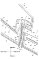
図1は、車両後部の複合ランプ1の水平断面図である。図2は、図1に示すII部の拡大図である。
FIG. 1 is a horizontal sectional view of a
この車両用複合ランプ1は車両の左後部に取り付けられる左リアランプであり、車両の右後部に取り付けられる右の車両用ランプはこの車両用複合ランプ1を左右反転させたものである。左後部の車両用複合ランプ1と右後部の車両用複合ランプは鏡像の関係にある。
The
車両用複合ランプ1は第一ランプユニット2及び第二ランプユニット4を有し、第一ランプユニット2と第二ランプユニット4が意匠的に一つのまとまりをもって組み合わせられている。
The
車両本体の後部に開口(例えばトランクの開口、後部ドアの開口等)が設けられ、その開口が車両の開閉部(例えば、バックドア又はトランクリッド)によって開閉される。第一ランプユニット2は、車両本体の後部の開口に隣接して、車両本体の後部に取り付けられている。第二ランプユニット4は、その開閉部の後面の車幅方向外側の縁部に取り付けられている。その開閉部が閉じられた場合、第二ランプユニット4が第一ランプユニット2よりも車幅方向内側に配置され、第一ランプユニット2と第二ランプユニット4が左右に並列されて、第一ランプユニット2と第二ランプユニット4が左右に隣り合う。また、第一ランプユニット2の車幅方向内側の部位が第二ランプユニット4の車幅方向外側の部位の背後(車両については前方である)に配置されて隠れている。車両の後から見た場合、第一ランプユニット2の車幅方向内側の端2aと第二ランプユニット4の車幅方向外側の端4aとの間に隙間6が存在するが、第一ランプユニット2が点灯した場合、その隙間6も光って見える。図1及び図2に示す「前」は複合ランプ1としての前であり、複合ランプ1によって光が主に照射される向きがこの「前」である。従って、図1及び図2に示す「前」は車両後方をいい、図1及び図2に示す「後」は車両前方をいう。
An opening (for example, opening of a trunk, opening of a rear door, etc.) is provided in the rear part of the vehicle body, and the opening is opened and closed by an opening / closing part (for example, a back door or a trunk lid) of the vehicle. The
第一ランプユニット2はハウジング21及びアウターレンズ(光を素通しする透明なアウターカバー)22を有する。ハウジング21が中空を有する箱形に設けられており、ハウジング21の前面が開口する。アウターレンズ22がハウジング21の前端に取り付けられ、ハウジング21の前面開口がアウターレンズ22によって閉塞される。こうして、ハウジング21及びアウターレンズ22の内側に灯室(中空)23が形成される。第二ランプユニット4についても同様であり、ハウジング41が第二ランプユニット4のハウジングであり、アウターレンズ(光を素通しする透明なアウターカバー)42が第二ランプユニット4のアウターレンズであり、灯室43が第二ランプユニット4の灯室である。
The
第一ランプユニット2のアウターレンズ22の前面の車幅方向内側の端部には、段状の凹部22aが形成されている。具体的には、アウターレンズ22の前面の車両方向内側の端部が後ろに向けて窪むように形成され、アウターレンズ22の車両方向内側の側面が車幅方向外側に窪むように形成され、これにより段状の凹部22aが形成される。そのため、凹部22aが前側にむけて開口するとともに、凹部22aが車幅方向内側にむけて開口する。
A stepped recess 22 a is formed at the inner end in the vehicle width direction of the front surface of the
凹部22aの後ろ側を構成するフランジ部22cが薄板状に設けられ、凹部22aの車幅方向外側を構成する側壁部22bも薄板状に設けられ、フランジ部22bが側壁部22bの後端から車幅方向内側へ延出し、上から見てフランジ部22c及び側壁部22bの組み合わせがL字状に形作られている。
A
第一ランプユニット2が車両本体に取り付けられた状態では、アウターレンズ22が前方(つまり車両後方)及び車幅方向外側へ向けられ、そのアウターレンズ22の前面が車両本体の表面と面一になる。第二ランプユニット4が開閉部に取り付けられた状態では、アウターレンズ42が前方へ向けられ、そのアウターレンズ42の前面が開閉部の表面と面一にあなる。また、開閉部が閉じられた状態では、第二ランプユニット4のハウジング41及びアウターレンズ42の車幅方向外側の部位が凹部22a内に配置され、アウターレンズ22のフランジ部22cがハウジング41及びアウターレンズ42の車幅方向外側の部位の背後に配置される。そのため、アウターレンズ22の前面とアウターレンズ42の前面との間に段差がなく、第一ランプユニット2と第二ランプユニット4が意匠的に一つのまとまりをもつ。また、第二ランプユニット4のハウジング41及びアウターレンズ42の車幅方向外側の部位が第一ランプユニット2のアウターレンズ21の車幅方向内側の部位の前に重なっても、開閉部の開閉に妨げとならない。
第二ランプユニット4のハウジング41及びアウターレンズ42の車幅方向外側の端面と第一ランプユニット2のアウターレンズ22の側壁部22bとの間に隙間6が形成される。
When the
A
第二ランプユニット4が帯状発光部44を有し、帯状発光部44が灯室43内に設けられている。帯状発光部44が前方へ向けられており、帯状発光部44から前方へ光が発せられる。帯状発光部44が車幅方向に延在するように設けられ、帯状発光部44が横長に設けられている。帯状発光部44は灯室43内の車幅方向外側の端部にまで至っている。
The
帯状発光部44は導光体45、反射板46及び光源47を利用したものである。導光体45が車幅方向に延在するよう帯板状に形成されている。導光体45の車幅方向内側の端面45aには、光源47が対向配置されている。この光源47は例えば発光ダイオードである。但し、光源47がバルブであってもよい。
The belt-like
光源47が点灯すると、光源47によって発せられた光が導光体45の端面45aに入射して導光体45の内部に取り込まれる。導光体45の内部に取り込まれた光は導光体45の後面45bと前面45cで反射を繰り返しながら、反対側の端面45dに向けてガイドされる。導光体45の後面45bが光制御面であり、その後面45bには複数の拡散反射部(例えば、レンズカット、プリズムカット、ドット又は断面三角形状の凸部等)が形成される。導光体45の内部を伝播する光が導光体45の後面45bによって前方へ拡散反射されることによって、導光体45の前面45cに入射される反射光のうち臨界角未満の成分が前面45cを通過して導光体45の後方へ出射する。反射板46が導光体45の後面45bに対向配置され、導光体45の後面45bからの漏れ光が反射板46によって後方へ反射されて、その反射光が導光体45を前方へ通過する。
When the
なお、帯状発光部44が導光体45を用いたもの以外であってもよい。例えば、複数の点状光源(例えば、発光ダイオード)を車幅方向に沿って配列したものを帯状発光部44として利用する。又は、面光源(例えば、有機EL素子)を車幅方向に延びるように帯状に形成したものを帯状発光部44として利用する。これら点状光源又は面光源を利用した帯状発光部44のうち車幅方向外側の端部の前に反射光学系(リフレクタ)を設け、帯状発光部44の車幅方向外側の端部から発した光がその反射光学系によってリフレクタ29に向けて反射されてもよい。
The band-shaped
灯室43内であって導光体45の前には、インナーレンズ(インナーカバー)48がアウターレンズ42の内面に沿った状態に設けられている。このインナーレンズ48が素通しの透明板であり、導光体45の前面45cから出射した光がインナーレンズ48を通過する。インナーレンズ48は無色透明又は有色透明である。なお、導光体45の前面45cから出射した光がインナーレンズ48の表面形状によって屈折して、その光が偏向又は拡散されてもよい。
An inner lens (inner cover) 48 is provided along the inner surface of the
第一ランプユニット2も帯状発光部24を有し、帯状発光部24が灯室23内に配置されている。この帯状発光部24は導光体25、反射板26及び光源27を利用したものである。
The
導光体25が車幅方向に延在するよう帯板状に形成されており、導光体25の車幅方向内側の端部が灯室23内の側壁部22b近傍にまで至っている。導光体25の車幅方向外側の端面25aには、光源27が対向配置されている。光源27は発光ダイオードである。導光体25の車幅方向外側の端面25aが光取込面であり、光源27が点灯すると、光源27によって発せられた光が導光体25の端面25aを通過して導光体25の内部に取り込まれる。
The
導光体25の後面25b及び前面25cが反射面であり、導光体25の内部に取り込まれた光が導光体25の後面25bと前面25cで反射を繰り返しながら、反対側の端面25dに向かってガイドされる。
The
導光体25の後面25bが反射面の他に光制御面を兼ね、導光体25の前面25cが反射面の他に出射面を兼ねる。つまり、複数の拡散反射部(例えば、レンズカット、プリズムカット、ドット、断面三角形状の凸部等)が導光体25の後面25bに形成され、導光体25の内部を伝播する光が導光体25の後面25bによって前方へ拡散反射されることによって、導光体25の前面25cに入射される反射光のうち臨界角未満の成分が前面25cを通過して導光体25の前方へ出射する。
The
反射板26が導光体25の後面25bに対向配置され、導光体25の後面25bからの漏れ光が反射板26によって前方へ反射されて、その反射光が導光体25を前方へ通過する。
The
導光体25の端面25dが導光体45の端面45dから車幅方向に離れており、導光体25の車幅方向内側の端部と導光体25の車幅方向外側の端部が前後に重なっていない。
The
灯室23内であって導光体25の前には、インナーレンズ(インナーカバー)28がアウターレンズ22の内面に沿った状態に設けられている。このインナーレンズ28が素通しの透明板であり、導光体25の前面25cから出射した光がインナーレンズ28を通過する。インナーレンズ28は無色透明又は有色透明である。なお、導光体25の前面25cから出射した光がインナーレンズ28の表面形状によって屈折して、その光が偏向又は拡散されてもよい。
An inner lens (inner cover) 28 is provided along the inner surface of the
導光体25の車幅方向内側の端面25dは導光体25の厚み方向に対して傾斜し、上から見た断面においては端面25dと後面25bによって挟まれる角が鋭角を成し、端面25dと前面25cによって挟まれる角が鈍角を成す。そのため、導光体25の端面5dまでガイドされた光は端面25dによって前方へ反射され、その反射光が導光体25の後面25bに臨界角未満で入射し、後面25bから導光体25の前方へ出射する。
An
導光体25が反射板26の車幅方向内側の縁26aから車幅方向内側へ延び出ており、導光体25の車幅方向内側の端面25dの後側には反射板26がない。そのため、導光体25の端面25dによって反射された光が後面25bから出射したら、その光が反射板26の車幅方向内側の縁26aの横を後方へ通過する。また、導光体25の後面25bのうち反射板26の縁26aからはみ出た部位から漏れた光も反射板26の車幅方向内側の縁26aの横を後方へ通過する。
The
導光体25の車幅方向内側の端面25dの後方には、リフレクタ29が配設されている。このリフレクタ29は灯室23内においてフランジ部22cの背後まで回り込むように設けられている。更に、リフレクタ29は、ハウジング41及びアウターレンズ42の車幅方向外側の部位の背後に回り込むように設けられている。更に、リフレクタ29は、導光体45の娑婆方向外側の部位の背後に回り込むように設けられている。
A
リフレクタ29の前面(反射面)は凹面(例えば、放物面型凹面)を基調として、その前面に沿って複数の微小反射面29aが配列されている。このリフレクタ29は、導光体25の後面25bのうち反射板26の縁26aからはみ出た部位から出射した光を車両後方に向けて反射して、その反射光を車幅方向に拡散させる。
The front surface (reflective surface) of the
インナーレンズ28の車幅方向内側の部位には光学素子部28aが設けられ、光学素子部28aがリフレクタ29の前方に配置されている。光学素子部28aは、アウターレンズ22の側壁部22b及びフランジ部22cとハウジング21の車幅方向内側の側面とに沿って、階段状に設けられている。つまり、光学素子部28aが2段の階段状に設けられた板状の側壁部28b,28dと、これら側壁部28b,28dの間に設けられた板状の段間部28cと、を有する。側壁部28bがインナーレンズ28の車幅方向内側の端から後方へ続き、段間部28cが側壁部28bの後端から車幅方向内側へ延出し、側壁部28dが段間部28cの車幅方向内側の端から後方へ延出する。そして、側壁部28bが灯室23内においてアウターレンズ22の側壁部22bに対向し、段間部28cが灯室23内においてフランジ部22cに対向し、側壁部28dが灯室23内においてハウジング21の側面に対向する。
An
側壁部22b,22d及び段間部28cの内面には、光拡散作用のある形状(例えば、フルートカット)が施されている。フルートカットとは、複数のシリンドリカル凸面を並列させたものである。具体的には、側壁部28b,28d及び段間部28cの内面に形成された複数のシリンドリカル凸面の円柱軸が水平方向(図2の紙面に対して平行な方向)に延在し、これらシリンドリカル凸面が上下方向(図2の紙面に垂直な方向)に配列されている。そのため、リフレクタ29によって反射された光が側壁部22b,22d及び段間部28cを通過する際に、その光が側壁部22b,22d及び段間部28cのフルートカットによって上下に拡散される。
The inner surfaces of the
リフレクタ29によって反射された光が前方に向かうので、車両用複合ランプ1を正面(車両の後方)から見た場合に、導光体25の端面25dと導光体45の端面45dとの間の部分(特に、隙間6)が光って見え、その部分が暗くならない。そのため、光源27,47が共に点灯すると、導光体25の入射面25aから導光体45の入射面45aまでひと繋がりの帯状部が発光しているように見える。つまり、導光体25の端面25dが導光体45の端面45dから車幅方向に離れていても、それら端面25d,45dの間も光っているように見える。
Since the light reflected by the
車両用複合ランプ1を正面から見た場合、リフレクタ29が側壁部22b,22d及び段間部28c越しに光って見える。ここで、側壁部22b,22d及び段間部28cの外面が光散乱面加工(例えばシボ加工)されており、リフレクタ29によって反射された光が側壁部22b,22d及び段間部28cを通過する際に散乱する。そのため、車両用複合ランプ1を正面から見た場合、リフレクタ29の光った見え方が導光体25,45の前面25c,45cの光った見え方に近づき、光学部品の違いによる発光の見え方の差を低減することができる。
When the vehicle
帯状発光部24,44が発光することによって示す信号は例えば車両後部、制動、後退、方向指示又は警告である。
The signals indicated by the light emission of the belt-like
〔変形例1〕
図3に示すように、灯室43内において、導光体45の車幅方向外側の端面45dが露出している。そして、アウターレンズ42及びインナーレンズ48の車幅方向外側の側面部42a,48aがアウターレンズ42及びインナーレンズ48の前面から端面45dよりも後側まで至っている。そして、アウターレンズ42及びインナーレンズ48の側面部42a,48aが導光体45の端面45dと導光体25の端面25dとの間に配置されている。更に、第一ランプユニット2の側壁部22b,28bも導光体45の端面45dと導光体25の端面25dとの間に配置されている。
[Modification 1]
As shown in FIG. 3, the
導光体45の端面45dから出射した光が側面部42a,48a及び側壁部22b,28bを通過する。一方、導光体25の端面25dから漏れた光が側壁部22b,28b及び側面部42a,48aを通過する。そのため、車両用複合ランプ1を正面から見た場合、隙間6が光って見え、第一ランプユニット2の帯状発光部24と第二ランプユニット4の帯状発光部44がひと繋がりの帯状に見える。
The light emitted from the
〔変形例2〕
リフレクタ29は、反射光を車幅方向のみならず、上下方向に拡散させる。この場合、側壁部22b,22d及び段間部28cの内面が滑らかであり、レンズカットが側壁部28b,28d及び段間部28cの内面に施されていない。
[Modification 2]
The
〔変形例3〕
リフレクタ29は、反射光を上下方向に拡散させる。この場合、側壁部22b,22d及び段間部28cの光拡散作用の形状(フルートカット)については、側壁部28b,28d及び段間部28cの内面に形成された複数のシリンドリカル凸面の円柱軸が上下方向(図2の紙面に垂直な方向)に延在し、これらシリンドリカル凸面が水平方向(図2の紙面に対して平行な方向)に配列されている。
そのため、リフレクタ29によって上下に拡散するよう反射された光が側壁部22b,22d及び段間部28cを通過する際に、その光が側壁部22b,22d及び段間部28cの光拡散作用の形状(フルートカットと呼ばれるレンズカット)によって水平方向に拡散される。
[Modification 3]
The
Therefore, when the light reflected so as to be diffused up and down by the
〔変形例4〕
側壁部22b,22d及び段間部28cの内面が滑らかな上で(レンズカットが施されていない上で)、光拡散加工(シボ加工)が側壁部28b,28d及び段間部28cの外面に施されている。或いは、側壁部28b,28d及び段間部28cの外面が滑らかな上で(光拡散加工が施されていない上で)、レンズカットが側壁部28b,28d及び段間部28cの内面に施されている。
[Modification 4]
The inner surfaces of the
〔変形例5〕
側壁部28b,28d及び段間部28cが光を素通しするものとする。つまり、レンズカットが側壁部28b,28d及び段間部28cの内面に施されておらず、光散乱加工(シボ加工)が側壁部28b,28d及び段間部28cの外面に施されていない。
[Modification 5]
The
1 車両用複合ランプ
2 第一ランプユニット
4 第二ランプユニット
6 隙間
21 ハウジング(第一ハウジング)
22 アウターレンズ(第一アウターレンズ)
25 導光体
25a 導光体の端面(第一端面)
25b 導光体の後面
25c 導光体の前面
25d 導光体の端面(第二端面)
27 光源
28a 光学素子部
29 リフレクタ
41 ハウジング(第二ハウジング)
42 アウターレンズ(第二アウターレンズ)
44 帯状発光部
DESCRIPTION OF
22 Outer lens (first outer lens)
25
25b Rear surface of the
27
42 Outer lens (second outer lens)
44 Band-shaped light emitting part
Claims (2)
前記第一ランプユニットが、前側が開口した第一ハウジングと、前記第一ハウジングの開口を塞ぐように前記第一ハウジングに取り付けられた透光性の第一アウターレンズと、前記第一ハウジング及び前記第一アウターレンズによって囲まれた第一灯室内において車幅方向に延びるように設けられた導光体と、前記導光体の車幅方向の両端面のうち前記第二ランプユニットの反対側の第一端面に対向配置された光源と、前記導光体の車幅方向の両端面のうち前記第二ランプユニット側の第二端面の後側に配置されたリフレクタと、を有し、
前記導光体が、前記光源によって発せられて前記第一端面に入射した光を前記第二端面に向けてガイドするとともに、その光を前記導光体の前面から前方へ出射させ、
前記導光体の前記第二端面が、前記導光体の前面に対して鈍角を成すように前記導光体の前面に対して傾斜し、前記導光体によってガイドされた光を後方へ反射し、
前記リフレクタが、前記第二端面によって反射されて前記導光体の後面から出射した光を前方に反射し、
前記第二ランプユニットが、前側が開口した第二ハウジングと、前記第二ハウジングの開口を塞ぐように前記第二ハウジングに取り付けられた透光性の第二アウターレンズと、前記第二ハウジング及び前記第二アウターレンズによって囲まれた第二灯室内において車幅方向に延びるように設けられ、前方に向けて発光する帯状発光部と、を有し、
前記第一アウターレンズの前記第二ランプユニット側の部位が、前記第二ハウジング及び前記第二アウターレンズの前記第一ランプユニット側の部位の背後に配置され、
前記リフレクタが、前記第二ハウジング及び前記第二アウターレンズの前記第一ランプユニット側の部位の背後に回り込むように設けられている
ことを特徴とする車両用複合ランプ。 In a vehicle composite lamp comprising a first lamp unit and a second lamp unit attached to a vehicle adjacent to each other in the vehicle width direction,
The first lamp unit includes a first housing having an open front side, a translucent first outer lens attached to the first housing so as to close the opening of the first housing, the first housing, and the A light guide provided to extend in the vehicle width direction in the first lamp chamber surrounded by the first outer lens, and the opposite side of the second lamp unit among both end faces of the light guide in the vehicle width direction. A light source disposed opposite to the first end surface, and a reflector disposed on the rear side of the second end surface on the second lamp unit side among both end surfaces in the vehicle width direction of the light guide,
The light guide is guided by the light emitted from the light source and incident on the first end surface toward the second end surface, and the light is emitted forward from the front surface of the light guide,
The second end surface of the light guide body is inclined with respect to the front surface of the light guide body so as to form an obtuse angle with respect to the front surface of the light guide body, and the light guided by the light guide body is reflected backward. And
The reflector reflects the light reflected from the second end face and emitted from the rear face of the light guide forward;
The second lamp unit includes a second housing having an open front side, a translucent second outer lens attached to the second housing so as to close the opening of the second housing, the second housing, and the A belt-shaped light emitting portion that is provided so as to extend in the vehicle width direction in the second lamp chamber surrounded by the second outer lens, and emits light forward.
The second lamp unit side portion of the first outer lens is disposed behind the second housing and the second lamp unit side portion of the second outer lens,
The vehicular composite lamp, wherein the reflector is provided so as to wrap around behind the portion of the second housing and the second outer lens on the first lamp unit side.
ことを特徴とする請求項1に記載の車両用複合ランプ。 The first lamp unit further includes an optical element unit that is disposed in front of the reflector and behind the first outer lens and diffuses light reflected by the reflector. The vehicle composite lamp as described.
Priority Applications (2)
| Application Number | Priority Date | Filing Date | Title |
|---|---|---|---|
| JP2014231169A JP2016095996A (en) | 2014-11-14 | 2014-11-14 | Composite lamp for vehicles |
| US14/940,395 US10036528B2 (en) | 2014-11-14 | 2015-11-13 | Vehicle combination lamp |
Applications Claiming Priority (1)
| Application Number | Priority Date | Filing Date | Title |
|---|---|---|---|
| JP2014231169A JP2016095996A (en) | 2014-11-14 | 2014-11-14 | Composite lamp for vehicles |
Publications (1)
| Publication Number | Publication Date |
|---|---|
| JP2016095996A true JP2016095996A (en) | 2016-05-26 |
Family
ID=55961329
Family Applications (1)
| Application Number | Title | Priority Date | Filing Date |
|---|---|---|---|
| JP2014231169A Pending JP2016095996A (en) | 2014-11-14 | 2014-11-14 | Composite lamp for vehicles |
Country Status (2)
| Country | Link |
|---|---|
| US (1) | US10036528B2 (en) |
| JP (1) | JP2016095996A (en) |
Cited By (3)
| Publication number | Priority date | Publication date | Assignee | Title |
|---|---|---|---|---|
| US10215360B1 (en) | 2018-05-18 | 2019-02-26 | Stanley Electric Co., Ltd. | Vehicle lighting device and method |
| JP2019053988A (en) * | 2017-09-13 | 2019-04-04 | スタンレー電気株式会社 | Vehicular lamp |
| CN113375121A (en) * | 2021-06-25 | 2021-09-10 | 东风汽车集团股份有限公司 | Automobile signal lamp, installation method thereof and automobile |
Families Citing this family (10)
| Publication number | Priority date | Publication date | Assignee | Title |
|---|---|---|---|---|
| GB2553525A (en) * | 2016-09-06 | 2018-03-14 | Jaguar Land Rover Ltd | A Lamp assembly for a vehicle, and a vehicle comprising such a lamp assembly |
| JP6885718B2 (en) * | 2016-12-27 | 2021-06-16 | 株式会社小糸製作所 | Vehicle combination lamps |
| US10151436B1 (en) * | 2017-10-12 | 2018-12-11 | GM Global Technology Operations LLC | Vehicle lighting assembly with light transfer optical system |
| ES2925031T3 (en) * | 2017-12-21 | 2022-10-13 | Marelli Automotive Lighting Italy Spa | Vehicle headlight with parts at different luminance levels |
| US10400981B1 (en) | 2018-05-18 | 2019-09-03 | Honda Motor Co., Ltd. | Lighting device |
| JP7512683B2 (en) * | 2020-05-29 | 2024-07-09 | 市光工業株式会社 | Vehicle lighting fixtures |
| JP7638170B2 (en) * | 2021-06-23 | 2025-03-03 | スタンレー電気株式会社 | Vehicle lighting fixtures |
| US11772546B2 (en) * | 2021-11-18 | 2023-10-03 | Valeo North America, Inc. | Edge lighting for a continuous illumination appearance |
| US12129986B1 (en) * | 2023-10-06 | 2024-10-29 | Valeo Vision | Closeout with flexible light guide for gap lighting |
| US12078316B1 (en) * | 2023-10-06 | 2024-09-03 | Valeo Vision | Window for gap lighting |
Family Cites Families (9)
| Publication number | Priority date | Publication date | Assignee | Title |
|---|---|---|---|---|
| FR2849157B1 (en) * | 2002-12-20 | 2015-07-10 | Valeo Vision | DEVICE FOR LIGHTING AND / OR SIGNALING THE PROJECTOR OR FIRE TYPE FOR A MOTOR VEHICLE |
| US20130265791A1 (en) * | 2012-04-10 | 2013-10-10 | Ford Global Technologies, Llc | Vehicle light assembly with photon recycling |
| JP5952086B2 (en) * | 2012-05-24 | 2016-07-13 | スタンレー電気株式会社 | Vehicle lighting |
| JP6159166B2 (en) | 2012-11-21 | 2017-07-05 | 株式会社小糸製作所 | Vehicle lighting |
| DE102012112075B4 (en) * | 2012-12-11 | 2021-07-01 | HELLA GmbH & Co. KGaA | Lighting device for vehicles, each with a flat light guide, covered by a lens and having scattering elements, on both sides of a joint |
| JP5652482B2 (en) * | 2013-01-17 | 2015-01-14 | トヨタ自動車株式会社 | Vehicle lamp structure |
| JP5945238B2 (en) * | 2013-03-11 | 2016-07-05 | 株式会社豊田自動織機 | Vehicle lamp and vehicle rear panel |
| JP6431319B2 (en) * | 2014-08-29 | 2018-11-28 | 株式会社小糸製作所 | Vehicle lighting |
| JP6511244B2 (en) * | 2014-10-10 | 2019-05-15 | 株式会社小糸製作所 | Lighting light guide |
-
2014
- 2014-11-14 JP JP2014231169A patent/JP2016095996A/en active Pending
-
2015
- 2015-11-13 US US14/940,395 patent/US10036528B2/en active Active
Cited By (6)
| Publication number | Priority date | Publication date | Assignee | Title |
|---|---|---|---|---|
| JP2019053988A (en) * | 2017-09-13 | 2019-04-04 | スタンレー電気株式会社 | Vehicular lamp |
| JP7202822B2 (en) | 2017-09-13 | 2023-01-12 | スタンレー電気株式会社 | vehicle lamp |
| US10215360B1 (en) | 2018-05-18 | 2019-02-26 | Stanley Electric Co., Ltd. | Vehicle lighting device and method |
| JP2020017518A (en) * | 2018-05-18 | 2020-01-30 | スタンレー電気株式会社 | Vehicle lamp assembly and method |
| JP7356259B2 (en) | 2018-05-18 | 2023-10-04 | スタンレー電気株式会社 | Vehicle lighting assembly and method |
| CN113375121A (en) * | 2021-06-25 | 2021-09-10 | 东风汽车集团股份有限公司 | Automobile signal lamp, installation method thereof and automobile |
Also Published As
| Publication number | Publication date |
|---|---|
| US10036528B2 (en) | 2018-07-31 |
| US20160138773A1 (en) | 2016-05-19 |
Similar Documents
| Publication | Publication Date | Title |
|---|---|---|
| JP2016095996A (en) | Composite lamp for vehicles | |
| JP6511244B2 (en) | Lighting light guide | |
| JP6381113B2 (en) | Vehicle lighting | |
| EP3671019B1 (en) | Vehicle lighting and/or signalling device | |
| JP5581824B2 (en) | Vehicle lighting | |
| JP6361248B2 (en) | Vehicle lighting | |
| JP4683648B2 (en) | Vehicle lamp | |
| JP6829973B2 (en) | Lamp unit | |
| JP2012064533A (en) | Lamp fitting for vehicle | |
| JPWO2020240664A5 (en) | ||
| JP6221589B2 (en) | Vehicle lighting | |
| WO2015178125A1 (en) | Vehicular light guide member and vehicular lamp fixture | |
| JP2015082443A (en) | Vehicular lighting fixture | |
| JP6039333B2 (en) | Vehicle lighting | |
| JP6343601B2 (en) | Vehicle lighting | |
| JP2017183231A (en) | Lamp | |
| JP2015153577A (en) | Vehicle lighting | |
| JP2008103273A (en) | Vehicular lighting fixture | |
| JP2015115205A (en) | Complex lamp for vehicle | |
| JP7579709B2 (en) | Vehicle lighting fixtures | |
| JP2017147120A (en) | Vehicular light guide member and vehicular lighting fixture | |
| JP2014229466A (en) | Vehicular lighting fixture | |
| JP6368992B2 (en) | Vehicle light guide member, vehicle lamp | |
| JP2017033777A (en) | Light guide body and vehicular lighting fixture including the same | |
| JP2015069905A (en) | Vehicle lamp fitting |