JP2016066042A - Image forming apparatus - Google Patents
Image forming apparatus Download PDFInfo
- Publication number
- JP2016066042A JP2016066042A JP2015021448A JP2015021448A JP2016066042A JP 2016066042 A JP2016066042 A JP 2016066042A JP 2015021448 A JP2015021448 A JP 2015021448A JP 2015021448 A JP2015021448 A JP 2015021448A JP 2016066042 A JP2016066042 A JP 2016066042A
- Authority
- JP
- Japan
- Prior art keywords
- image
- forming apparatus
- unit
- image forming
- carrier
- Prior art date
- Legal status (The legal status is an assumption and is not a legal conclusion. Google has not performed a legal analysis and makes no representation as to the accuracy of the status listed.)
- Pending
Links
Images


Landscapes
- Dry Development In Electrophotography (AREA)
- Electrostatic Charge, Transfer And Separation In Electrography (AREA)
- Control Or Security For Electrophotography (AREA)
- Discharging, Photosensitive Material Shape In Electrophotography (AREA)
Abstract
Description
本発明は、プリンタ、ファクシミリ、複写機などの画像形成装置に関するものである。 The present invention relates to an image forming apparatus such as a printer, a facsimile machine, and a copying machine.
従来、この種の画像形成装置としては、特許文献1に記載のものが知られている。この画像形成装置は、像担持体たるドラム状の感光体と、感光体に接触しながら回転する帯電ローラと、感光体に対して所定の間隙を介して対向しながら回転する現像ローラとを備えている。そして、帯電バイアスを印加している帯電ローラによって感光体の表面を一様に帯電させた後、帯電後の表面を露光装置によって露光して潜像を形成する。その後、現像ローラの表面上に担持している現像剤によって潜像を現像してトナー像を得る。感光体上のトナー像は、最終的に記録媒体である用紙に転写して用紙上に画像を形成する。
Conventionally, as this type of image forming apparatus, the one described in
かかる構成において、帯電ローラが偏心していると、帯電ローラの回転周期に同期した帯電ムラが感光体の表面に発生する。そして、このような帯電ムラにより、帯電ローラの回転周期と同じ周期で画像濃度を増減させる周期的な画像濃度ムラが発生してしまう。また、感光体や現像ローラが偏心していると、感光体や現像ローラの回転に伴って感光体と現像ローラとの間隙(以下、現像ギャップという)が変動し、これに伴って感光体と現像ローラとの間に形成される現像電界の強度が変動する。このような現像電界の強度変動により、感光体や現像ローラの回転周期と同じ周期で画像濃度を増減させる周期的な画像濃度ムラが発生してしまう。そして、帯電ローラ、感光体、及び、現像ローラそれぞれの回転周期と同じ周期で発生する周期的な画像濃度ムラの周期が重なると、画像濃度ムラが悪化するといった問題が生じる。 In such a configuration, when the charging roller is eccentric, uneven charging is generated on the surface of the photoreceptor in synchronization with the rotation period of the charging roller. Such charging unevenness causes periodic image density unevenness that increases or decreases the image density in the same cycle as the rotation period of the charging roller. Further, when the photosensitive member and the developing roller are eccentric, the gap between the photosensitive member and the developing roller (hereinafter referred to as a developing gap) varies with the rotation of the photosensitive member and the developing roller. The intensity of the developing electric field formed between the rollers varies. Such fluctuations in the intensity of the developing electric field cause periodic image density unevenness that increases or decreases the image density in the same cycle as the rotation cycle of the photosensitive member or the developing roller. Then, when periodic image density unevenness cycles that occur at the same period as the rotation cycle of the charging roller, the photoconductor, and the developing roller overlap, there arises a problem that the image density unevenness deteriorates.
本発明は以上の問題点に鑑みなされたものであり、その目的は、画像濃度ムラを低減させることができる画像形成装置を提供することである。 The present invention has been made in view of the above problems, and an object thereof is to provide an image forming apparatus capable of reducing image density unevenness.
上記目的を達成するために、請求項1の発明は、回転可能に設けられた像担持体と、前記像担持体の表面を帯電する回転可能に設けられた帯電部材と、前記像担持体の表面に潜像を形成する潜像形成手段と、回転可能に設けられた現像剤担持体に担持した現像剤により前記像担持体上の潜像を現像する現像手段とを備えた画像形成装置において、前記像担持体または前記現像剤担持体の1回転周期で生じる像担持体表面移動方向の画像濃度変動を検出する第一画像濃度変動検出手段と、前記帯電部材の1回転周期で生じる像担持体表面移動方向の画像濃度変動を検出する第二画像濃度変動検出手段と、前記第一画像濃度変動検出手段及び前記第二画像濃度変動検出手段の検出結果に基づき、前記像担持体または前記現像剤担持体の1回転周期で生じる画像濃度変動の周期及び位相に対して、前記帯電部材の1回転周期で生じる画像濃度変動の周期が同一且つ位相が逆位相となるように、該帯電部材の回転を制御する制御手段を有することを特徴とするものである。
In order to achieve the above-mentioned object, the invention of
以上、本発明によれば、画像濃度ムラを低減させることができるという優れた効果がある。 As described above, according to the present invention, there is an excellent effect that unevenness in image density can be reduced.
図2は、画像形成装置1のハードウェア構成図である。図3は、画像形成装置1の制御部10のハードウェア構成図である。画像形成装置1は、記録媒体の一例としての用紙にトナー像を定着させることにより画像を形成する。画像形成装置1は、図2に示すように制御部10、画像読取部11、作像部12、給紙部13、転写部14、定着部15、排紙部16、及び、表示・操作部17等を有している。
FIG. 2 is a hardware configuration diagram of the
制御部10は、図3に示すようにCPU(Central Processing Unit)1011、メインメモリ(MEM−P)1012、ノースブリッジ(NB)1013、サウスブリッジ(SB)1014、AGP(Accelerated Graphics Port)バス1015、ASIC(Application Specific Integrated Circuit)1016、ローカルメモリ(MEM−C)1017、HD(Hard Disk)1018、HDD(Hard Disk Drive)1019、ネットワークI/F102を有している。
As shown in FIG. 3, the
CPU1011は、メインメモリ1012に記憶されたプログラムに従って、データを加工・演算したり、画像読取部11、作像部12、給紙部13、転写部14、定着部15、及び、排紙部16の動作を制御したりするものである。メインメモリ1012は制御部10の記憶領域であり、ROM(Read Only Memory)1012a、RAM(Random Access Memory)1012bを有している。ROM1012aは、制御部10の各機能を実現させるプログラムやデータの格納用メモリである。ROM1012aに記憶されているプログラムは、インストール可能な形式または実行可能な形式のファイルでCD−ROM、FD、CD−R、DVD等のコンピュータで読み取り可能な記録媒体に記録して提供するように構成してもよい。
The
RAM1012bは、プログラムやデータの展開、及び、メモリ印刷時の描画用メモリなどとして用いる。NB1013は、CPU1011と、MEM−P1012、SB1014、及び、AGPバス1015とを接続するためのブリッジである。SB1014は、NB1013とPCIデバイス、周辺デバイスとを接続するためのブリッジである。AGPバス1015は、グラフィック処理を高速化するために提案されたグラフィックスアクセラレータカード用のバスインタフェースである。
The
ASIC1016は、PCIターゲット及びAGPマスタ、ASIC1016の中核をなすアービタ(ARB)、MEM−C1017を制御するメモリコントローラ、ハードウェアロジックなどにより画像データの回転などを行う複数のDMAC(Direct Memory Access Controller)からなる。このASIC1016は、PCIバスを介してUSB(Universal Serial Bus)のインターフェースや、IEEE1394(Institute of Electrical and Electronics Engineers 1394)のインターフェースに接続されている。
The ASIC 1016 includes a PCI target and an AGP master, an arbiter (ARB) that forms the core of the ASIC 1016, a memory controller that controls the MEM-
MEM−C1017は、コピー用画像バッファ及び符号バッファとして用いるローカルメモリである。HD1018は、画像データの蓄積、印刷時に用いるフォントデータの蓄積、フォームの蓄積を行うためのストレージである。HDD1019は、CPU1011の制御にしたがってHD1018に対するデータの読み出し又は書き込みを制御する。ネットワークI/F102は、通信ネットワークを介して情報処理装置等の外部機器と情報を送受信する。
The MEM-C 1017 is a local memory used as a copy image buffer and a code buffer. The
この制御部10には、画像形成ユニット120C,120M,120Y,120K,120Tや、トナー像検知センサ69などが電気的に接続されている。そして、制御部10は、ROM1012a内に記憶している制御プログラムに基づいて、これらの各種の機器を制御するようになっている。また、ROM1012aRAM1012bには、トナー像検知センサ69の検出値からトナー濃度(トナー付着量)を算出するときに用いる出力換算情報を記憶している。この出力換算情報としては、例えば、出力換算データ(変換テーブル)や出力換算式(アルゴリズム)等である。
The
画像読取部11は、用紙に記載されている画像を光学的に読み取ることにより、画像情報を生成するものである。具体的には、用紙に光を当てて、その反射光をCCD(Charge Coupled Devices)、または、CIS(Contact Image Sensor)等の読取センサで受光することによって画像情報を読み取る。なお、画像情報とは、用紙等の記録媒体に形成させる画像を表す情報であり、赤(R)、緑(G)、青(B)の各色を示す電気的な色分解画像信号を用いて示されたものである。 The image reading unit 11 generates image information by optically reading an image written on a sheet. Specifically, the image information is read by applying light to a sheet and receiving the reflected light by a reading sensor such as a CCD (Charge Coupled Devices) or a CIS (Contact Image Sensor). The image information is information representing an image to be formed on a recording medium such as paper, and uses electrical color separation image signals indicating red (R), green (G), and blue (B) colors. It is shown.
画像読取部11は、図2に示すようにコンタクトガラス111や読取センサ112等を有している。コンタクトガラス111は、画像が記載されている用紙が載置されるものである。読取センサ112は、コンタクトガラス111に載置されている用紙に記載されている画像の画像情報を読み取るものである。
The image reading unit 11 includes a contact glass 111, a
作像部12は、画像読取部11によって読み取られた画像情報、または、ネットワークI/F102によって受信された画像情報に基づいて、転写部14の中間転写ベルト143の表面にトナーを付着させて画像(トナー像)を形成するものである。
The
作像部12は、画像形成ユニット120C、画像形成ユニット120M、画像形成ユニット120Y、画像形成ユニット120K、及び、画像形成ユニット120Tを備えている。画像形成ユニット120Cは、シアン(C)色のトナーを有する現像剤を用いてトナー像を形成するものである。画像形成ユニット120Mは、マゼンタ(M)色のトナーを用いてトナー像を形成するものである。画像形成ユニット120Yは、イエロー(Y)色のトナーを用いてトナー像を形成するものである。画像形成ユニット120Kは、ブラック(K)色のトナーを用いてトナー像を形成するものである。画像形成ユニット120Tは、クリア(T)トナーを用いてトナー像を形成するものである。
The
なお、以降ではC色トナー、M色トナー、Y色トナー、K色トナーのいずれか一以上のトナーを有色トナーという。それぞれの有色トナーは、顔料や染料等の色材を含有した帯電性をもった樹脂粒子である。 Hereinafter, one or more of the C color toner, the M color toner, the Y color toner, and the K color toner is referred to as a colored toner. Each colored toner is a resin particle having a charging property containing a coloring material such as a pigment or a dye.
また、クリアトナーとは、無色透明のトナーであり、記録媒体に付着された有色トナーに付着されるとその有色トナーを視認できるように構成された樹脂粒子である。また、クリアトナーは記録媒体に付着されるとその記録媒体を視認できる樹脂粒子である。クリアトナーは、たとえば、低分子量のポリエステル樹脂に二酸化ケイ素(SiO2)や二酸化チタン(TiO2)を外添することによって生成される。なお、クリアトナーは記録媒体または記録媒体上に付着された有色トナーを視認できる程度の量であれば、色材を含んでいてもよい。 Further, the clear toner is a colorless and transparent toner, and is a resin particle configured so that the colored toner can be visually recognized when attached to the colored toner attached to the recording medium. The clear toner is resin particles that can be visually recognized when attached to the recording medium. The clear toner is produced, for example, by externally adding silicon dioxide (SiO 2 ) or titanium dioxide (TiO 2 ) to a low molecular weight polyester resin. Note that the clear toner may contain a coloring material as long as the amount is such that the recording medium or the colored toner attached on the recording medium can be visually recognized.
以降では、画像形成ユニット120C、画像形成ユニット120M、画像形成ユニット120Y、画像形成ユニット120K、画像形成ユニット120Tのうち、任意の画像形成ユニットを「画像形成ユニット120」と表す。
Hereinafter, of the image forming unit 120C, the
画像形成ユニット120Cは、現像剤収容部121C、感光体ドラム122C、帯電部123C、露光部124C、現像部125C、除電部126C、清掃部127C、及び、電位検知部128Cを備えている。
The image forming unit 120C includes a developer container 121C, a photosensitive drum 122C, a charging unit 123C, an exposure unit 124C, a developing unit 125C, a
現像剤収容部121Cは、C色のトナーを収容しており、現像部125Cに対してC色のトナーを供給するものである。現像剤収容部121Cに収容されているトナーは、現像剤収容部121C内の搬送スクリューが駆動することによって所定の量だけ現像部125Cに供給される。 The developer storage unit 121C stores C-color toner, and supplies the C-color toner to the development unit 125C. The toner accommodated in the developer accommodating portion 121C is supplied to the developing portion 125C by a predetermined amount by driving the conveying screw in the developer accommodating portion 121C.
現像部125Cには、駆動モータによって回転駆動される筒状の現像ローラ125aCが配設されており、この現像ローラ125aCは現像部125Cのケーシングに設けられた開口から自らの周面の一部をケーシング外に露出させている。そして、その現像ローラ125aCの露出箇所を、所定間隔の現像ギャップをあけて感光体ドラム122Cに対向させている。 The developing unit 125C is provided with a cylindrical developing roller 125aC that is rotationally driven by a drive motor. The developing roller 125aC is configured to remove a part of its peripheral surface from an opening provided in the casing of the developing unit 125C. It is exposed outside the casing. The exposed portion of the developing roller 125aC is opposed to the photosensitive drum 122C with a developing gap of a predetermined interval.
感光体ドラム122Cは、帯電部123Cにより表面が一様に帯電され、制御部10から受け取った画像情報に基づき、露光部124Cによって表面に静電潜像が形成されるものである。また、感光体ドラム122Cは、静電潜像が形成された表面に、現像部125Cがトナーを付着させることによってトナー像が形成される。また、感光体ドラム122Cは、中間転写ベルト143に接するように設けられ、中間転写ベルト143との接点で中間転写ベルト143の移動方向と同じ方向に回転するように設けられている。
The surface of the photosensitive drum 122C is uniformly charged by the charging unit 123C, and an electrostatic latent image is formed on the surface by the exposure unit 124C based on the image information received from the
帯電部123Cは、感光体ドラム122Cの表面と接触させて配置された帯電ローラ23Cを有している。そして、帯電ローラ23Cに電圧を印加することにより、帯電ローラ23Cと感光体ドラム122Cとの間で放電を発生させて、感光体ドラム122Cの表面を一様に帯電させる。また、帯電部123Cには、帯電ローラ23Cの表面に接触して回転し帯電ローラ表面をクリーニングする帯電クリーニング部材としての帯電クリーニングローラが設けられている。なお、感光体ドラム122Cの表面と帯電ローラ23Cとの間に微小な隙間をあけて、感光体ドラム122Cに対し帯電ローラ23Cを近接させて配置してもよい。 The charging unit 123C has a charging roller 23C disposed in contact with the surface of the photosensitive drum 122C. Then, by applying a voltage to the charging roller 23C, a discharge is generated between the charging roller 23C and the photosensitive drum 122C, and the surface of the photosensitive drum 122C is uniformly charged. The charging unit 123C is provided with a charging cleaning roller as a charging cleaning member that rotates in contact with the surface of the charging roller 23C and cleans the surface of the charging roller. The charging roller 23C may be disposed close to the photosensitive drum 122C with a minute gap between the surface of the photosensitive drum 122C and the charging roller 23C.
露光部124Cは、帯電部123Cによって帯電された感光体ドラム122Cの表面に、制御部10によって決定されたC色の網点面積率に基づいて光を照射して静電潜像を形成する。現像部125Cは、露光部124Cによって感光体ドラム122Cの表面に形成された静電潜像に対して現像剤収容部121Cに収容されているC色のトナーを付着させることによって現像し、トナー像を形成する。
The exposure unit 124C irradiates the surface of the photosensitive drum 122C charged by the charging unit 123C with light based on the C halftone dot area ratio determined by the
除電部126Cは、中間転写ベルト143に画像が転写された後の感光体ドラム122Cの表面を除電する。清掃部127Cは、除電部126Cによって除電された感光体ドラム122Cの表面に残った転写残トナーを除去する。電位検知部128Cは、感光体ドラム122Cの電位を検知する。
The
画像形成ユニット120Mは、現像剤収容部121M、感光体ドラム122M、帯電部123M、露光部124M、現像部125M、除電部126M、清掃部127M、及び、電位検知部128Mを備えている。現像剤収容部121Mは、M色のトナーを収容している。
The
画像形成ユニット120Yは、現像剤収容部121Y、感光体ドラム122Y、帯電部123Y、露光部124Y、現像部125Y、除電部126Y、清掃部127Y、及び、電位検知部128Yを備えている。現像剤収容部121Yは、Y色のトナーを収容している。
The
画像形成ユニット120Kは、現像剤収容部121K、感光体ドラム122K、帯電部123K、露光部124K、現像部125K、除電部126K、清掃部127K、及び、電位検知部128Kを備えている。現像剤収容部121Kは、K色のトナーを収容している。
The
画像形成ユニット120Tは、現像剤収容部121T、感光体ドラム122T、帯電部123T、露光部124T、現像部125T、除電部126T、清掃部127T、及び、電位検知部128Tを備えている。現像剤収容部121Tは、クリアトナーを収容している。
The
なお、以降では、現像剤収容部121C、現像剤収容部121M、現像剤収容部121Y、現像剤収容部121K、現像剤収容部121Tのうち、任意の現像剤収容部を「現像剤収容部121」と表す。また、感光体ドラム122C、感光体ドラム122M、感光体ドラム122Y、感光体ドラム122K、感光体ドラム122Tのうち、任意の感光体ドラムを「感光体ドラム122」と表す。また、帯電部123C、帯電部123M、帯電部123Y、帯電部123K、帯電部123Tのうち、任意の帯電部を「帯電部123」と表す。
In the following description, any developer accommodating portion among the developer accommodating portion 121C, the
また、露光部124C、露光部124M、露光部124Y、露光部124K、露光部124Tのうち、任意の露光部を「露光部124」と表す。また、現像部125C、現像部125M、現像部125Y、現像部125K、現像部125Tのうち、任意の現像部を「現像部125」と表す。また、除電部126C、除電部126M、除電部126Y、除電部126K、除電部126Tのうち、任意の除電部を「除電部126」と表す。また、清掃部127C、清掃部127M、清掃部127Y、清掃部127K、清掃部127Tのうち、任意の清掃部を「清掃部127」と表す。また、電位検知部128C、電位検知部128M、電位検知部128Y、電位検知部128K、電位検知部128Tのうち、任意の電位センサを「電位検知部128」と表す。
Further, among the exposure unit 124C, the
給紙部13は、転写部14に対して用紙を供給するものである。給紙部13は、用紙収容部131、給紙ローラ132、及び、レジストローラ134を備えている。用紙収容部131は、記録媒体の一例である用紙を収容している。給紙ローラ132は、用紙収容部131に収容されている用紙を用紙搬送路133の方へ移動させるために回転するように設けられている。このように設けられている給紙ローラ132は、収容されている用紙のうち最上段にある用紙を一枚ずつ繰り出して、用紙搬送路133へ給紙する。
The
給紙ローラ132によって用紙搬送路133に給紙された用紙は、複数の搬送ローラ対135a,135bにより用紙搬送路133を通って転写部14に搬送される。レジストローラ134は、後述する中間転写ベルト143のトナー像が形成されている部分が、転写部14に到達されるタイミングで用紙搬送路133を搬送された用紙を送り出すものである。
The sheet fed to the
転写部14は、作像部12によって感光体ドラム122に形成された画像を中間転写ベルト143に一次転写し、中間転写ベルト143に転写された画像を用紙に二次転写するものである。転写部14は、駆動ローラ141、従動ローラ142、中間転写ベルト143、一次転写ローラ144C,144M,144Y,144K,144T、二次転写対向ローラ145、及び、二次転写ローラ146を備えている。
The
中間転写ベルト143は、駆動ローラ141及び従動ローラ142に掛け渡され、駆動ローラ141の回転とともに感光体ドラム122に接しながら移動するものである。なお、従動ローラ142は、中間転写ベルト143が移動するとともに回転する。中間転写ベルト143が感光体ドラム122に接しながら移動することによって、感光体ドラム122に形成された画像が中間転写ベルト143の表面に転写される。
The
一次転写ローラ144C,144M,144Y,144K,144Tは、中間転写ベルト143を挟んで、それぞれ感光体ドラム122C,122M,122Y,122K,122Tと対向して設けられており、中間転写ベルト143を移動させるように回転する。二次転写ローラ146は、二次転写対向ローラ145との間に中間転写ベルト143と用紙とを挟みこんで回転する。
The
定着部15は、転写部14によって用紙に転写されたトナーを定着させる。定着とは、トナーに熱と圧力を同時に加えることによってトナーの樹脂成分を用紙に溶着させることである。転写部14によって用紙に転写されたトナーに定着処理が行われることによって、用紙上のトナーの状態は安定したものとなる。
The fixing
定着部15には、定着ベルト152、定着ローラ153、定着ベルト搬送ローラ154、定着対向ローラ155及び発熱部156が設けられている。転写部14によってトナーが転写された用紙は、用紙搬送路151を通って定着部15に向けて搬送される。定着ベルト152は、定着ローラ153と定着ベルト搬送ローラ154とに掛け渡されており、それらのローラが回転することによって移動する。定着ローラ153の内部には発熱部156が設置されており、発熱することで定着ローラ153を介して用紙を加熱する。定着ローラ153は、定着ベルト152を挟んで対向して設置されている定着対向ローラ155との間で、用紙搬送路151を搬送された用紙を挟み込み、用紙及び用紙上のトナーを加熱及び加圧して、用紙にトナーを定着させる。
The fixing
排紙部16は、定着部15でトナーが定着された用紙を画像形成装置内から排出するものであり、排紙ローラ162、排紙口163、及び、排紙トレイ164を有している。定着部15によって定着処理された用紙は、排紙搬送路161を通って排紙口163に向かって搬送される。排紙ローラ162は、排紙搬送路161を搬送された用紙を排紙口163から排出し排紙トレイ164に収容する。
The
表示・操作部17は、パネル表示部171及び操作部172を有している。パネル表示部171には設定値や選択画面等が表示される。また、パネル表示部171は、ユーザーからの入力を受け付けるタッチパネル等である。操作部172は、画像形成にかかる諸条件を受け付けるテンキーや、複写開始指示を受け付けるスタートキー等のユーザーが入力をするために操作を行うものである。
The display /
ここで、画像形成装置では、画像濃度変化が少ないことが望まれる。作像プロセスの中で円筒状の部品が多用されるが、回転体部品の振れにより周期的な画像濃度ムラが発生する。これは、回転体(感光体ドラム、現像ローラ、帯電ローラ)が偏心していたり真円でなかったりすることによって、感光体ドラム−帯電ローラ間のギャップや、感光体ドラム−現像ローラ間のギャップが、回転体の1回転周期で変動する。これにより、帯電ムラや現像ムラが生じるためである。周期的な画像濃度ムラなどの画像品質の観点から、それら回転体(感光体ドラム、現像ローラ、帯電ローラ)には、高い振れ精度が求められる。ただし、求められる振れ精度は数[μm]以下であるため加工精度の限界であり、精度のみに品質を求めるとコストが高くなる。そのため、他のアプローチにより画像濃度変化を少なくする必要がある。 Here, in the image forming apparatus, it is desired that the image density change is small. Cylindrical parts are frequently used in the image forming process, but periodic image density unevenness occurs due to the shake of the rotating body parts. This is because the gap between the photosensitive drum and the charging roller or the gap between the photosensitive drum and the developing roller is caused by the eccentricity of the rotating body (photosensitive drum, developing roller, charging roller) or not being a perfect circle. And fluctuates in one rotation cycle of the rotating body. This is because charging unevenness and development unevenness occur. From the viewpoint of image quality such as periodic image density unevenness, the rotating bodies (photosensitive drum, developing roller, charging roller) are required to have high shake accuracy. However, since the required runout accuracy is several [μm] or less, it is the limit of machining accuracy, and cost is increased when quality is obtained only by accuracy. Therefore, it is necessary to reduce the change in image density by another approach.
なお、回転体の回転周期で画像濃度ムラが発生している場合、回転体の線速V[mm/s]を回転体の円周X[mm]で割ると、回転体は1秒間に(V/X)回転するので、(V/X)[Hz]の画像濃度ムラ発生周波数で画像濃度ムラが発生することになる。例えば、現像ローラ125aの線速Vが560[mm/s]であり、現像ローラ125aの円周Xが80[mm]のときには、現像ローラ125aは1秒間に7回転するので、7[Hz]の画像濃度ムラ発生周波数で画像濃度ムラが発生する。
In addition, when the image density unevenness is generated in the rotation cycle of the rotating body, dividing the linear velocity V [mm / s] of the rotating body by the circumference X [mm] of the rotating body ( Therefore, the image density unevenness occurs at the image density unevenness occurrence frequency of (V / X) [Hz]. For example, when the linear velocity V of the developing
図2に示す画像形成装置1は、中間転写ベルト143の表面に形成されたトナー像の濃度を検知する濃度検知手段として、光学センサなどで構成されたトナー像検知センサ69を備えている。トナー像検知センサ69は、中間転写ベルト143の駆動ローラ141に巻き付いている部分に対向する位置に配置されている。このトナー像検知センサ69により、画像濃度ムラの補正制御に用いるように中間転写ベルト143の表面に形成された画像パターンのトナー像の濃度を検知することができる。
The
図4は、画像濃度ムラの補正制御(検出)に用いる画像パターンの一例を示す説明図である。この例では、中間転写ベルト143の表面におけるトナー像検知センサ69に対向する部分に、中間転写ベルト移動方向Xに長尺な帯状の画像パターン900を形成している。この画像パターン900は、感光体ドラム122や現像ローラ125aなどの各回転体の位相を検出するために、少なくとも位相検出対象の回転体1回転周期以上の長さとしている。例えば、感光体ドラム1回転周期の画像濃度ムラを検出する場合には、画像パターン900の長さを少なくとも感光体ドラム周長Lp以上の長さとする。また、現像ローラ1回転周期の画像濃度ムラを検出する場合には、画像パターン900の長さを少なくとも現像ローラ周長Lq以上の長さとする。
FIG. 4 is an explanatory diagram illustrating an example of an image pattern used for image density unevenness correction control (detection). In this example, a belt-like image pattern 900 that is long in the intermediate transfer belt moving direction X is formed on the surface of the
図5は、トナー像検知センサ69の概略構成を示す断面図である。図5に示すように、トナー像検知センサ69は、主に、発光手段としてのLEDなどからなる発光素子311と、正反射光を受光するための正反射受光素子312と、拡散反射光を受光するための拡散反射受光素子313とから構成されている。
FIG. 5 is a cross-sectional view showing a schematic configuration of the toner
トナー像検知センサ69は、発光素子311から中間転写ベルト143の表面に向けて光を出射する。そして、中間転写ベルト143の表面や、その表面上にあるトナー像で正反射した正反射光を正反射受光素子312によって受光して、受光量に応じた電圧を出力する。更に、中間転写ベルト143の表面や、その表面上にあるトナー像で拡散反射した拡散反射光を拡散反射受光素子313によって受光して、受光量に応じた電圧を出力する。このようにして検知された、正反射光の受光量に応じた電圧と、拡散反射光の受光量に応じた電圧とから、中間転写ベルト143上のトナー像の画像濃度(トナー付着量)が算出される。
The toner
このように、本実施形態の画像形成装置1では、感光体ドラム122や中間転写ベルト143の表面移動方向である副走査方向の画像濃度変動を、トナー像検知センサ69の検知結果に基づいて検出し、その検出された値から画像濃度変動の位相や振幅を算出する。
As described above, in the
図6は、帯電ローラ23の位相や回転数を検出する位相・回転数検出手段としての帯電ローラ位相・回転数検出装置であるエンコーダ70の説明図である。
FIG. 6 is an explanatory diagram of an
エンコーダ70は、帯電ローラ23Y,23M,23C,23K,23Tのそれぞれに対して別個に設けられているが、互いに同構成であって、図6に示す構成となっている。また、図6に示されているように、帯電ローラ23は、その回転中心軸をなすローラ軸76が、カップリング77を介して駆動モータ78の出力軸である駆動伝達軸79に接続されている。そして、駆動モータ78の駆動によって回転駆動されるようになっている。
The
エンコーダ70は、駆動伝達軸79と一体に設けられ駆動伝達軸79の回転に伴って回転移動する遮光部材72と、発光部71aと受光部71bとが設けられたフォトインタラプタ71とを有している。遮光部材72にはスリット72aが形成されており、帯電ローラ23の回転に従い、フォトインタラプタ71の発光部71aからの光を順じ遮光部材72及びスリット72aにより透過と遮断とを繰返し、それに従い受光部71bがその光を順じ受光する。
The
これにより、遮光部材72の回転量に応じてパルス状のON/OFF信号を得ている。このパルス状のON/OFF信号を用いて帯電ローラ23の移動角(以下、角変位と称す)を求めることで、帯電ローラ23の位相(回転位置)を検出したり、帯電ローラ23の回転数(線速)を検出したりするようになっている。
Thereby, a pulse-like ON / OFF signal is obtained according to the rotation amount of the
位相(回転位置)や回転数(線速)を検出する構成としては、感光体ドラム122の位相(回転位置)を検知する感光体ホームポジションセンサも、エンコーダ70と同様にして感光体ドラム122の回転位置を検出するようになっている。
As a configuration for detecting the phase (rotation position) and the number of rotations (linear velocity), a photoconductor home position sensor that detects the phase (rotation position) of the photoconductor drum 122 is also the same as the
図6に示した例では、帯電ローラ23の駆動に関し、駆動モータ直結のダイレクトドライブ方式を用いているが、駆動モータ78からの動力伝達の間に減速機構が入っていても良い。ただし、減速機構を採用する場合、遮光部材72は帯電ローラ23と同じ回転数になるよう、ローラ軸76上に設置しておくことが望ましい。このことは、感光体ドラム122の位相(回転位置)を検出する場合についても同様である。
In the example shown in FIG. 6, a direct drive system directly connected to the drive motor is used for driving the charging
回転体の位相・回転数検出装置は、帯電ローラ23以外の回転体である現像ローラ125aや感光体ドラム122にも取り付けられているが、その構成は同様である。
The rotating body phase / rotation number detecting device is also attached to the developing
各回転体のエンコーダ出力とトナー像検知センサ出力の該当回転体周期の濃度ムラを算出することで、該当回転体の位相と濃度ムラの位相との相関を求めることができる。そして、位相を調整し他の回転体による濃度ムラと逆位相に制御することで輻走査方向の濃度ムラを抑制できる。 By calculating the density unevenness of the rotating body cycle of the encoder output and toner image detection sensor output of each rotating body, the correlation between the phase of the corresponding rotating body and the phase of the density unevenness can be obtained. Then, density unevenness in the radial scanning direction can be suppressed by adjusting the phase and controlling the phase opposite to the density unevenness due to the other rotating body.
図7は、中間転写ベルト143上に形成された画像パターン900を検知したトナー像検知センサ69のセンサ出力と、エンコーダ70のセンサ出力との関係を示したグラフである。図7に示すように、帯電ローラ23の1回転周期毎に、エンコーダ70の出力が矩形状に1回だけ立ち上がっている。この立ち上がりのタイミングは、帯電ローラ23が所定の回転角度姿勢になったタイミングである。そして、図7からわかるように、トナー像検知センサ69のセンサ出力すなわち中間転写ベルト143上に形成された画像パターン900の画像濃度に、帯電ローラ1回転周期で変動が生じていることがわかる。
FIG. 7 is a graph showing the relationship between the sensor output of the toner
このように帯電ローラ周期で画像に縞状の画像濃度ムラが発生し得る。これは、感光体ドラム122に帯電ローラ23を接触させて設ける構成では、感光体ドラム122と帯電ローラ23とを回転させており、帯電ローラ23の偏心などに起因して、感光体ドラム122と帯電ローラ23との接触幅が変動する。そのため、感光体ドラム122と帯電ローラ23との接触位置を感光体ドラム122が通過する時間が変動してしまい、感光体ドラム122を一様な電位に帯電することができず、帯電ムラが生じる。すると、露光部124で感光体ドラム122を同じ強度で露光しても潜像の電位がばらついてしまい、最終的に、画像に帯電ムラに応じた画像濃度ムラが発生してしまう。
In this way, striped image density unevenness may occur in the image at the charging roller cycle. In the configuration in which the charging
帯電ローラ23によって帯電せしめた感光体ドラム122の表面電位を、帯電ローラ23の回転位置を検出する回転位置検出手段と同期して計測し、計測した感光体ドラム122の表面電位から帯電ローラ周期の帯電ムラ(電位ムラ)を検出する。
The surface potential of the photosensitive drum 122 charged by the charging
図8に示すように、帯電ローラ23や現像ローラ125aなどの各回転体のフレなどによる画像濃度ムラ周期が重なることで、用紙上に形成された画像の画像濃度ムラが悪化する。そこで、電位検知部128により感光体ドラム122の表面電位を検知し、感光体ドラム122の帯電ローラ1回転周期で生じる帯電ムラ(電位ムラ)の位相を検出する。また、トナー像検知センサ69により中間転写ベルト143上に形成された画像パターン900の画像濃度を検知し、画像パターン900の現像ローラ1回転周期で生じる画像濃度ムラの位相を検出する。
As shown in FIG. 8, the image density unevenness of the image formed on the paper is deteriorated by overlapping the image density unevenness periods due to the flare of each rotating body such as the charging
本実施形態の画像形成装置1では、駆動モータ78により帯電ローラ23を感光体ドラム122や現像ローラ125aなどとは独立させて回転させることができる。そのため、現像ローラ125aの1回転周期で生じる画像濃度変動の周期及び位相に対して、帯電ローラ23の1回転周期で生じる画像濃度変動の周期が同一且つ位相が逆位相となるように、帯電ローラの回転を制御する。
In the
具体的には、駆動モータ78を制御して帯電ローラ23の回転数を変更させることにより、帯電ローラ23の1回転周期を現像ローラ125aの1回転周期と同一にする。また、エンコーダ70により検知された帯電ローラ23の回転位置と対応させて、帯電ローラ23の1回転周期で生じる画像濃度変動の位相を予め検出しておく。そして、現像ローラ125aの1回転周期で生じる画像濃度変動の位相に対して、帯電ローラ23の1回転周期で生じる画像濃度変動の位相が逆位相となるような回転位置をとるように、帯電ローラ23の回転を制御する。
Specifically, by controlling the
これにより、図1に示すように、現像ローラ125aの1回転周期で生じる画像濃度変動と、帯電ローラ23の1回転周期で生じる画像濃度変動とが画像上で打ち消しあい、感光体ドラム表面移動方向である副走査方向の画像濃度ムラが低減し目立たなくなる。
As a result, as shown in FIG. 1, the image density fluctuation generated in one rotation cycle of the developing
各回転体(感光体ドラム122、現像ローラ125a、帯電ローラ23)の位相調整動作の制御としては、次のように行うことができる。まず、中間転写ベルト143上に各回転体の1周期以上の画像パターンを形成し、中間転写ベルト143上の画像パターンのトナー付着量の変動データをトナー像検知センサ69で読み取る。そして、この読み取った中間転写ベルト143上のトナー付着量の変動データをフーリエ変換することで、各周波数(周期)でのトナー付着量の振幅・位相を算出する。このように算出した各回転体(感光体ドラム122、現像ローラ125a、帯電ローラ23)周期でのトナー付着量の振幅・位相と、該当する回転体の位相の相関を取得する。
Control of the phase adjustment operation of each rotating body (photosensitive drum 122, developing
そして、先に算出した各周波数でのトナー付着量の振幅が、現像ローラ125a>感光体ドラム122であれば、現像ローラ周期の濃度ムラに対して同一周期になるように、帯電ローラ23の駆動モータ回転数を変更する。また、現像ローラ周期の濃度ムラに対して帯電ローラ周期の濃度ムラが逆位相となるように位相を調整する。一方、各周波数でのトナー付着量の振幅が、現像ローラ125a<感光体ドラム122であれば、感光体ドラム周期に対して帯電ローラ周期・位相を調整する。また、各周波数でのトナー付着量の振幅が、現像ローラ125a<帯電ローラ23、且つ、感光体ドラム122<帯電ローラ23であれば、帯電ローラ23を回転させない。
Then, if the amplitude of the toner adhesion amount at each frequency calculated above is the developing
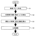
図9は、本実施形態の画像形成装置1で行われる位相調整動作の制御に係るフローチャートである。まず、画像パターンを形成し(S1)、現像ローラ125aと帯電ローラ23それぞれの1回転周期の画像濃度(電位)ムラを検知する(S2)。その検知結果に基づいて、制御部10により現像ローラ125aと帯電ローラ23それぞれの画像濃度ムラ周期・位相・振幅を算出する(S3)。そして、現像ローラ125aの1回転周期で生じる画像濃度変動の位相に対して、帯電ローラ23の1回転周期で生じる画像濃度変動の位相が逆位相となるような回転位置をとるように、帯電ローラ23の回転を制御して位相調整を行う(S4)。
FIG. 9 is a flowchart relating to the control of the phase adjustment operation performed in the
なお、上記内容は、現像ローラ125aを感光体ドラム122にしてもよい。すなわち、現像ギャップの周期的な変動は、現像ローラ125aの偏心のみではなく、感光体ドラム122の偏心によっても生じる。このため、本実施形態の画像形成装置1では、現像ローラ125aの位相(回転位置)と、感光体ドラム122の位相(回転位置)とをそれぞれ検知する。そして、トナー像検知センサ69の検知結果の濃度変動データから、現像ローラ125aの回転周期に起因する濃度変動と、感光体ドラム122の回転周期に起因する濃度変動とがそれぞれ取り出し可能となっている。これにより、現像ローラ125aと感光体ドラム122それぞれに起因する濃度変動を考慮して、濃度変動を抑制するように補正制御を行うことが可能となっている。
In the above description, the developing
また、現像ローラ125aまたは感光体ドラム122の1回転周期で生じる画像濃度変動の位相に対する、帯電ローラ23の1回転周期で生じる画像濃度変動の位相の調整は、印刷時よりも低い回転数で実施することで、位相調整の精度を高めることができる。
In addition, the adjustment of the phase of the image density fluctuation occurring in one rotation cycle of the charging
また、中間転写ベルト143上の画像パターン900からトナー像検知センサ69の検知結果に基づいて、現像ローラ125aと感光体ドラム122それぞれの1回転周期で生じる画像濃度変動を検出するような構成も採用することができる。この場合、感光体ドラム122の1回転周期で生じる画像濃度変動が検出されないときには、帯電ローラ23の回転制御を次のように行う。すなわち、現像ローラ125aの1回転周期で生じる画像濃度変動の周期及び位相に対して、帯電ローラ23の1回転周期で生じる画像濃度変動の周期が同一且つ位相が逆位相となるように、帯電ローラ23の回転を制御する。これにより、現像ローラ125aの1回転周期で生じる画像濃度ムラを低減させることができる。
A configuration is also employed in which image density fluctuations that occur in each rotation cycle of the developing
一方、現像ローラ125aの1回転周期で生じる画像濃度変動が検出されないときには、帯電ローラ23の回転制御を次のように行う。すなわち、感光体ドラム122の1回転周期で生じる画像濃度変動の周期及び位相に対して、帯電ローラ23の1回転周期で生じる画像濃度変動の周期が同一且つ位相が逆位相となるように、帯電ローラ23の回転を制御する。これにより、感光体ドラム122の1回転周期で生じる画像濃度ムラを低減させることができる。
On the other hand, when the image density fluctuation generated in one rotation cycle of the developing
さらに、感光体ドラム122及び現像ローラ125aそれぞれの1回転周期で生じる画像濃度変動が検出されないときは、作像中に帯電ローラ23を回転させない。これにより、帯電ローラ23の1回転周期で生じる画像濃度ムラの発生を抑制することができる。また、このとき、連続画像形成を行うときの先行用紙の後端と後続用紙の先端との間に対応する紙間で、帯電ローラ23を回転させる。これにより、感光体ドラム122と帯電ローラ23との摩耗量が減少し長寿命化を図ることができる。
Further, when the image density fluctuation generated in one rotation period of each of the photosensitive drum 122 and the developing
図10(a)に、感光体ドラム122と帯電ローラ23との間での速度差と摩擦係数との関係を示す。図10(b)に、感光体ドラム122と帯電ローラ23との間での摩擦係数と感光体ドラム摩耗量との関係を示す。図10(a)に示すように、感光体ドラム122と帯電ローラ23との間に速度差が発生すると、感光体ドラム122と帯電ローラ23との間での摩擦係数が大きくなる。そして、図10(b)に示すように、感光体ドラム122と帯電ローラ23との間での摩擦係数が大きくなると、走行距離あたりの感光体ドラム摩耗量が増加する。そのため、感光体ドラム122の寿命を考えると感光体ドラム122と帯電ローラ23との間に速度差をつけないことが望ましい。
FIG. 10A shows the relationship between the speed difference between the photosensitive drum 122 and the charging
図11に、帯電ローラ回転数と帯電ローラクリーニング性との関係を示す。図11からわかるように、帯電ローラクリーニング時の帯電ローラ回転数を変化させることで、十分なクリーニング性を確保するための必要な時間が異なる。また、クリーニング時間によっても十分なクリーニング性を確保するための必要時間が異なる。そのため、帯電ローラクリーニング時に帯電ローラ回転数を上げることにより、十分なクリーニング性を確保するための必要時間を短縮させることが可能となりダウンタイムを低減できる。 FIG. 11 shows the relationship between the charging roller rotation speed and the charging roller cleaning property. As can be seen from FIG. 11, the time required for ensuring sufficient cleaning differs by changing the rotation speed of the charging roller during charging roller cleaning. Also, the time required to ensure sufficient cleaning properties varies depending on the cleaning time. Therefore, by increasing the number of rotations of the charging roller at the time of cleaning the charging roller, it is possible to shorten the time required to ensure sufficient cleaning properties and reduce downtime.
また、画像形成動作開始前や画像形成動作終了後などの印刷時以外に、帯電クリーニングローラによって帯電ローラ23の表面をクリーニングするときには、印刷時よりも帯電ローラ23の回転数を上げるのが好ましい。これにより、帯電クリーニングローラによる帯電ローラ23のクリーニング性を向上させることができる。
Further, when the surface of the charging
図12に、印刷時の回転数で位相検知を行った場合のトナー像検知センサ69の出力を示す。図13に、印刷時よりも低い回転数で位相検知を行った場合のトナー像検知センサ69の出力を示す。印刷時の回転数で位相の検出や調整を行うと、図12に示すように他のノイズによる影響を強く受けるため、濃度ムラの位相と回転体の位相の間のズレが生じてしまう可能性が高くなる。そこで、位相の検出や調整を行うときには、印刷時よりも低い回転数で実施することで、図13に示すようにノイズの影響を低減させることができ、濃度ムラ位相と回転体位相とを精度良く検出することができる。
FIG. 12 shows the output of the toner
図14は、実施形態に係る他の画像形成装置である複写機100の概略構成図である。図14に示す複写機100は、四連タンデム型中間転写方式のフルカラー機の構成例を示している。
FIG. 14 is a schematic configuration diagram of a copying
図14において、中間転写ベルト143の展張面(張架面)に沿って、画像形成ユニット120C,120M,120Y,120Kが並設されている。イエローの画像形成ユニット120Yを代表して説明すると、画像形成ユニット120Yに設けられた感光体ドラム122Yの回りにはその回転方向順に、帯電部123Y、露光部124Y、現像手段としての現像部125Yが配置されている。さらに、一次転写ローラ144Y、清掃部127Y、除電部126Yが配置されている。
In FIG. 14,
なお、帯電部123Yには、感光体ドラム122Yの表面と所定間隔の帯電ギャップをあけて帯電ローラ23Yが設けられている。また、現像部125Yには、駆動モータによって回転駆動される筒状の現像ローラ125aが、所定間隔の現像ギャップをあけて感光体ドラム122Yに対向させて設けられている。露光部124の上方には、画像読み取り手段としての画像読取部11、自動原稿供給装置(ADF)40等が設けられている。
The charging
中間転写ベルト143は、駆動ローラ141や従動ローラ142や二次転写対向ローラ145などの張架ローラによって回転可能に張架されており、従動ローラ142に対向する部位にはベルトクリーニングユニット50が設けられている。二次転写対向ローラ145に対向する部位には、転写手段としての二次転写ローラ146が設けられている。
The
装置本体の下部には、2つの給紙部13a,13bが設けられている。給紙部13a,13bには、記録媒体である用紙を収容する用紙収容部131a,131bが設けられている。用紙収容部131a,131bに収容された用紙は、給紙ローラ132a,132bで用紙搬送路133に給紙された後、各搬送ローラ対135a,135b,135cで搬送され、レジストローラ134により所定のタイミングで二次転写部へ送られる。
Two paper feeders 13a and 13b are provided at the lower part of the apparatus main body. The paper supply units 13a and 13b are provided with paper storage units 131a and 131b for storing paper as a recording medium. The paper stored in the paper storage portions 131a and 131b is fed to the
二次転写部の用紙搬送方向下流側には、定着手段としての定着部15が設けられている。定着部15は、定着ローラ153、定着対向ローラ155及び発熱部156を有している。二次転写部でトナーが転写された用紙は、用紙搬送路151を通って定着部15に向けて搬送される。定着ローラ153の内部には発熱部156が設置されており、発熱することで定着ローラ153を介して用紙を加熱する。定着ローラ153は、定着ベルト152を挟んで対向して設置されている定着対向ローラ155との間で、用紙搬送路151を搬送された用紙を挟み込み、用紙及び用紙上のトナーを加熱及び加圧して、用紙にトナーを定着させる。
A fixing
排紙部16は、定着部15でトナーが定着された用紙を画像形成装置内から排出するものであり、排紙ローラ162、排紙口163、及び、排紙トレイ164を有している。排紙部16では、定着部15によって定着処理され排紙搬送路161を通って排紙口163に向かって搬送された用紙を、排紙ローラ162により排紙口163から排出し排紙トレイ164に収容する。
The
また、複写機100は、中間転写ベルト143の外周面に形成されたトナー像の濃度を検知する濃度検知手段として、光学センサなどで構成されたトナー像検知センサ69を備えている。このトナー像検知センサ69により、画像濃度ムラの補正制御に用いるように中間転写ベルト143の表面に形成された画像パターンのトナー像の濃度を検知することができる。図14の例では、中間転写ベルト143の駆動ローラ141に巻き付いている部分に対向する位置に、トナー像検知センサ69が配置されている。
Further, the copying
図14に示す構成において、画像形成動作を一通り説明する。プリント開始命令が入力されると、感光体ドラム122の周辺、中間転写ベルト143の周辺及び給紙搬送経路等にある各ローラが既定のタイミングで回転し始め、下部の用紙収容部131から用紙の給紙が開始される。
In the configuration shown in FIG. 14, an image forming operation will be described. When a print start command is input, the rollers around the photosensitive drum 122, the
一方、感光体ドラム122は、帯電部123によってその表面を一様な電位に帯電され、露光部124から照射される書込み光によってその表面を画像データに従って露光される。露光された後の電位パターンを静電潜像と呼ぶが、この静電潜像を担持した感光体ドラム122の表面に、現像部125からトナーを供給されることにより、感光体ドラム122に担持されている静電潜像が特定色に現像される。図14の構成においては感光体ドラム122が四色分あるので、各感光体ドラム122Y,122M,122C,122K上に、それぞれイエロー、マゼンタ、シアン、ブラックのトナー像が現像されることになる。
On the other hand, the surface of the photosensitive drum 122 is charged to a uniform potential by the charging
各感光体ドラム122Y,122M,122C,122K上のトナー像は、中間転写ベルト143との接点において、感光体ドラム122に対向して設置された一次転写ローラ144によって中間転写ベルト143上に転写される。この一次転写動作を、タイミングを合わせながら四色分繰り返すことにより、中間転写ベルト143上にフルカラートナー像が形成される。
The toner images on the respective
中間転写ベルト143上に形成されたフルカラートナー像は、二次転写部において、レジストローラ134によってタイミングを合わせて搬送されてくる用紙に転写される。この時、二次転写ローラ146に印加される二次転写バイアス及び押圧力によって二次転写が行われる。フルカラートナー像が転写された用紙は、定着部15を通過することにより、その用紙の表面に担持されているトナー像が加熱定着される。
The full-color toner image formed on the
片面プリントならばそのまま直線搬送されて排紙トレイ164へ搬送され、両面プリントならば搬送方向を下向きに変えられ用紙反転部30へ搬送されていく。用紙反転部30へ到達した用紙は、ここでスイッチバックローラ対27により搬送方向を逆転されて紙の後端から用紙反転部30を出て行く。これをスイッチバック動作と呼び、この動作によって用紙の表裏を反転させることができる。表裏反転された用紙は定着部方向には戻らず、再給紙搬送路31を通過して本来の給紙経路に合流する。この後は表面プリントの時と同じ様にトナー像を転写されて、定着部15を通過して排紙される。これが両面プリント動作である。
If it is single-sided printing, it is straightly conveyed and conveyed to the
また、一次転写部を通過した感光体ドラム122の表面には一次転写残トナーを担持しており、これをブレード及びブラシ等で構成された清掃部127により除去される。その後、除電部126によってその表面を一様に除電されて次の画像のための帯電に備える。また、二次転写部を通過した中間転写ベルト143に関しても、その表面に二次転写残トナーを担持しているが、こちらもブレード及びブラシ等で構成されたベルトクリーニングユニット50によってこれを除去され、次のトナー像の転写に備える。この様な動作の繰り返しで、片面プリント若しくは両面プリントが行われる。
Further, the primary transfer residual toner is carried on the surface of the photosensitive drum 122 that has passed through the primary transfer portion, and this is removed by a cleaning
そして、このような図14に示す複写機100においても、図2に示す画像形成装置1を用いて説明したような、図9に示す位相調整動作制御などの種々の制御を実行することにより、画像濃度ムラを低減させることができる。
14 also executes various controls such as the phase adjustment operation control shown in FIG. 9 as described using the
以上に説明したものは一例であり、本発明は、次の態様毎に特有の効果を奏する。
(態様A)
回転可能に設けられた感光体ドラム122などの像担持体と、像担持体の表面を帯電する回転可能に設けられた帯電ローラ23などの帯電部材と、像担持体の表面に潜像を形成する露光部124などの潜像形成手段と、回転可能に設けられた現像ローラ125aなどの現像剤担持体に担持した現像剤により像担持体上の潜像を現像する現像部125などの現像手段とを備えた画像形成装置1などの画像形成装置において、像担持体または現像剤担持体の1回転周期で生じる像担持体表面移動方向の画像濃度変動を検出するトナー像検知センサ69などの第一画像濃度変動検出手段と、帯電部材の1回転周期で生じる像担持体表面移動方向の画像濃度変動を検出する電位検知部128などの第二画像濃度変動検出手段と、第一画像濃度変動検出手段及び第二画像濃度変動検出手段の検出結果に基づき、像担持体または現像剤担持体の1回転周期で生じる画像濃度変動の周期及び位相に対して、帯電部材の1回転周期で生じる画像濃度変動の周期が同一且つ位相が逆位相となるように、帯電部材の回転を制御する制御部10などの制御手段を有する。
(態様A)においては、帯電部材の回転を制御して、像担持体または現像剤担持体の1回転周期で生じる画像濃度変動の周期及び位相に対し、帯電部材の1回転周期で生じる画像濃度変動の周期が同一且つ位相が逆位相となるようにする。これにより、このような帯電部材の回転制御を行った後、像担持体上に画像を形成したときに、像担持体または現像剤担持体の1回転周期で生じる画像濃度変動と、帯電部材の1回転周期で生じる画像濃度変動とが画像上で打ち消しあう。よって、その分、画像濃度変動を小さくでき、像担持体表面移動方向の画像濃度ムラを低減させることができる。
(態様B)
(態様A)において、前記第二画像濃度変動検出手段は、前記像担持体の表面電位を検知する電位検知部128などの表面電位検知手段と、帯電部材の回転位置を検知するエンコーダ70などの第二回転位置検知手段とを有する。これによれば、上記実施形態について説明したように、帯電部材の回転位置と対応させて、帯電部材の1回転周期で生じる画像濃度変動を検出することができる。
(態様C)
(態様A)または(態様B)において、前記第一画像濃度変動検出手段は、画像のトナー付着量を検知するトナー像検知センサ69などのトナー付着量検知手段と、前記像担持体または前記現像剤担持体の回転位置を検知する位相・回転数検出装置などの第一回転位置検知手段とを有する。これによれば、上記実施形態について説明したように、像担持体または現像剤担持体の回転位置と対応させて、像担持体または現像剤担持体の1回転周期で生じる画像濃度変動を検出することができる。
(態様D)
(態様A)、(態様B)または(態様C)において、前記帯電部材をクリーニングする帯電クリーニングローラなどの帯電クリーニング手段を有しており、帯電クリーニング手段によって前記帯電部材をクリーニングするときには、印刷時よりも帯電部材の回転数を上げる。これによれば、上記実施形態について説明したように、帯電クリーニング手段による帯電部材のクリーニング性を向上させることができる。
(態様E)
(態様A)、(態様B)、(態様C)または(態様D)において、前記像担持体または前記現像剤担持体の1回転周期で生じる画像濃度変動の位相に対する、前記帯電部材の1回転周期で生じる画像濃度変動の位相の調整は、印刷時よりも低い回転数で実施する。これによれば、上記実施形態について説明したように、位相調整の精度を高めることができる。
(態様F)
(態様A)、(態様B)、(態様C)、(態様D)または(態様E)において、前記像担持体の1回転周期で生じる画像濃度変動が検出されないときは、前記現像剤担持体の1回転周期で生じる画像濃度変動の周期及び位相に対して、前記帯電部材の1回転周期で生じる画像濃度変動の周期が同一且つ位相が逆位相となるように、前記制御手段が帯電部材の回転を制御する。これによれば、上記実施形態について説明したように、現像剤担持体の1回転周期で生じる画像濃度ムラを低減させることができる。
(態様G)
(態様A)、(態様B)、(態様C)、(態様D)または(態様E)において、前記現像剤担持体の1回転周期で生じる画像濃度変動が検出されないときは、前記像担持体の1回転周期で生じる画像濃度変動の周期及び位相に対して、前記帯電部材の1回転周期で生じる画像濃度変動の周期が同一且つ位相が逆位相となるように、前記制御手段が帯電部材の回転を制御する。これによれば、上記実施形態について説明したように、像担持体の1回転周期で生じる画像濃度ムラを低減させることができる。
(態様H)
(態様A)、(態様B)、(態様C)、(態様D)または(態様E)において、前記像担持体及び前記現像剤担持体それぞれの1回転周期で生じる画像濃度変動が検出されないときは、作像中に前記帯電部材を回転させない。これによれば、上記実施形態について説明したように、帯電部材の1回転周期で生じる画像濃度ムラの発生を抑制することができる。
(態様I)
(態様H)において、連続画像形成を行うときの先行用紙の後端と後続用紙の先端との間に対応する紙間で、前記帯電部材を回転させる。これによれば、上記実施形態について説明したように、像担持体と帯電部材との摩耗量が減少し長寿命化を図ることができる。
(態様J)
(態様I)において、前記紙間での前記像担持体の回転速度と前記帯電部材の回転速度とを同じにする。これによれば、上記実施形態について説明したように、像担持体と帯電部材との摩耗量をより減少させることができ、像担持体や帯電部材の長寿命化を図ることができる。
What has been described above is merely an example, and the present invention has a specific effect for each of the following modes.
(Aspect A)
A latent image is formed on the surface of the image carrier, such as an image carrier such as a photosensitive drum 122 provided rotatably, a charging member such as a charging
In (Aspect A), by controlling the rotation of the charging member, the image density generated in one rotation cycle of the charging member with respect to the cycle and phase of the image density fluctuation generated in one rotation cycle of the image carrier or developer carrier. The period of variation is the same and the phase is reversed. Thus, after such rotation control of the charging member is performed, when an image is formed on the image carrier, image density fluctuations that occur in one rotation cycle of the image carrier or developer carrier, and the charging member Image density fluctuations that occur in one rotation cycle cancel each other on the image. Therefore, the image density fluctuation can be reduced correspondingly, and the image density unevenness in the moving direction of the image carrier surface can be reduced.
(Aspect B)
In (Aspect A), the second image density fluctuation detecting means includes a surface potential detecting means such as a potential detecting unit 128 that detects the surface potential of the image carrier and an
(Aspect C)
In (Aspect A) or (Aspect B), the first image density fluctuation detection means includes a toner adhesion amount detection means such as a toner
(Aspect D)
In (Aspect A), (Aspect B), or (Aspect C), a charging cleaning unit such as a charging cleaning roller that cleans the charging member is provided. When the charging member is cleaned by the charging cleaning unit, printing is performed. Rather than increasing the number of rotations of the charging member. According to this, as described in the above embodiment, the cleaning property of the charging member by the charging cleaning unit can be improved.
(Aspect E)
In (Aspect A), (Aspect B), (Aspect C) or (Aspect D), one rotation of the charging member with respect to the phase of the image density fluctuation occurring in one rotation period of the image carrier or the developer carrier. The adjustment of the phase of the image density fluctuation occurring in the cycle is performed at a lower rotation speed than during printing. According to this, as described in the above embodiment, the accuracy of phase adjustment can be improved.
(Aspect F)
In (Aspect A), (Aspect B), (Aspect C), (Aspect D) or (Aspect E), when the variation in image density occurring in one rotation cycle of the image carrier is not detected, the developer carrier The control means controls the charging member so that the period and phase of the image density fluctuation generated in one rotation period of the charging member are the same and the phase is opposite to the period and phase of the image density fluctuation generated in one rotation period. Control the rotation. According to this, as described in the above embodiment, it is possible to reduce image density unevenness that occurs in one rotation cycle of the developer carrier.
(Aspect G)
In (Aspect A), (Aspect B), (Aspect C), (Aspect D), or (Aspect E), when no variation in image density that occurs in one rotation period of the developer carrier is detected, the image carrier The control means controls the charging member so that the period and phase of the image density fluctuation generated in one rotation period of the charging member are the same and the phase is opposite to the period and phase of the image density fluctuation generated in one rotation period. Control the rotation. According to this, as described in the above embodiment, it is possible to reduce image density unevenness that occurs in one rotation cycle of the image carrier.
(Aspect H)
In (Aspect A), (Aspect B), (Aspect C), (Aspect D) or (Aspect E), when image density fluctuations occurring in one rotation period of each of the image carrier and the developer carrier are not detected Does not rotate the charging member during image formation. According to this, as described in the above embodiment, it is possible to suppress the occurrence of uneven image density that occurs in one rotation cycle of the charging member.
(Aspect I)
In (Aspect H), the charging member is rotated between the corresponding papers between the trailing edge of the preceding paper and the leading edge of the succeeding paper when performing continuous image formation. According to this, as described in the above embodiment, the wear amount between the image carrier and the charging member is reduced, and the life can be extended.
(Aspect J)
In (Aspect I), the rotational speed of the image carrier and the rotational speed of the charging member between the papers are the same. According to this, as described in the above embodiment, the amount of wear between the image carrier and the charging member can be further reduced, and the life of the image carrier and the charging member can be extended.
1 画像形成装置
10 制御部
11 画像読取部
12 作像部
13 給紙部
14 転写部
15 定着部
16 排紙部
17 表示・操作部
23 帯電ローラ
27 スイッチバックローラ対
30 用紙反転部
31 再給紙搬送路
40 自動原稿供給装置
50 ベルトクリーニングユニット
69 トナー像検知センサ
70 エンコーダ
71 フォトインタラプタ
71a 発光部
71b 受光部
72 遮光部材
72a スリット
76 ローラ軸
77 カップリング
78 駆動モータ
79 駆動伝達軸
100 複写機
111 コンタクトガラス
112 読取センサ
120 画像形成ユニット
121 現像剤収容部
122 感光体ドラム
123 帯電部
124 露光部
125 現像部
126 除電部
127 清掃部
128 電位検知部
131 用紙収容部
132 給紙ローラ
133 用紙搬送路
134 レジストローラ
135 搬送ローラ対
141 駆動ローラ
142 従動ローラ
143 中間転写ベルト
144 一次転写ローラ
145 二次転写対向ローラ
146 二次転写ローラ
151 用紙搬送路
152 定着ベルト
153 定着ローラ
154 定着ベルト搬送ローラ
155 定着対向ローラ
156 発熱部
161 排紙搬送路
162 排紙ローラ
163 排紙口
164 排紙トレイ
171 パネル表示部
172 操作部
311 発光素子
312 正反射受光素子
313 拡散反射受光素子
900 画像パターン
1012 メインメモリ
1015 AGPバス
DESCRIPTION OF
Claims (10)
前記像担持体の表面を帯電する回転可能に設けられた帯電部材と、
前記像担持体の表面に潜像を形成する潜像形成手段と、
回転可能に設けられた現像剤担持体に担持した現像剤により前記像担持体上の潜像を現像する現像手段とを備えた画像形成装置において、
前記像担持体または前記現像剤担持体の1回転周期で生じる像担持体表面移動方向の画像濃度変動を検出する第一画像濃度変動検出手段と、
前記帯電部材の1回転周期で生じる像担持体表面移動方向の画像濃度変動を検出する第二画像濃度変動検出手段と、
前記第一画像濃度変動検出手段及び前記第二画像濃度変動検出手段の検出結果に基づき、前記像担持体または前記現像剤担持体の1回転周期で生じる画像濃度変動の周期及び位相に対して、前記帯電部材の1回転周期で生じる画像濃度変動の周期が同一且つ位相が逆位相となるように、該帯電部材の回転を制御する制御手段を有することを特徴とする画像形成装置。 An image carrier provided rotatably;
A rotatable charging member for charging the surface of the image carrier;
Latent image forming means for forming a latent image on the surface of the image carrier;
In an image forming apparatus comprising: a developing unit that develops a latent image on the image carrier with a developer carried on a developer carrier that is rotatably provided;
First image density fluctuation detecting means for detecting an image density fluctuation in the moving direction of the image carrier generated in one rotation period of the image carrier or the developer carrier;
Second image density fluctuation detecting means for detecting an image density fluctuation in the moving direction of the image carrier surface generated in one rotation cycle of the charging member;
Based on the detection results of the first image density fluctuation detection means and the second image density fluctuation detection means, with respect to the period and phase of the image density fluctuation that occurs in one rotation period of the image carrier or the developer carrier, An image forming apparatus comprising control means for controlling the rotation of the charging member so that the period of image density fluctuations generated in one rotation period of the charging member is the same and the phase is opposite.
前記第二画像濃度変動検出手段は、前記像担持体の表面電位を検知する表面電位検知手段と、前記帯電部材の回転位置を検知する第二回転位置検知手段とを有することを特徴とする画像形成装置。 The image forming apparatus according to claim 1.
The second image density variation detecting means includes a surface potential detecting means for detecting a surface potential of the image carrier and a second rotational position detecting means for detecting a rotational position of the charging member. Forming equipment.
前記第一画像濃度変動検出手段は、画像のトナー付着量を検知するトナー付着量検知手段と、前記像担持体または前記現像剤担持体の回転位置を検知する第一回転位置検知手段とを有することを特徴とする画像形成装置。 The image forming apparatus according to claim 1, wherein
The first image density fluctuation detecting means includes a toner adhesion amount detecting means for detecting a toner adhesion amount of an image, and a first rotational position detecting means for detecting a rotational position of the image carrier or the developer carrier. An image forming apparatus.
前記帯電部材をクリーニングする帯電クリーニング手段を有しており、
前記帯電クリーニング手段によって前記帯電部材をクリーニングするときには、印刷時よりも該帯電部材の回転数を上げることを特徴とする画像形成装置。 The image forming apparatus according to claim 1, 2 or 3.
A charging cleaning means for cleaning the charging member;
An image forming apparatus characterized in that when the charging member is cleaned by the charging cleaning means, the number of rotations of the charging member is higher than that during printing.
前記像担持体または前記現像剤担持体の1回転周期で生じる画像濃度変動の位相に対する、前記帯電部材の1回転周期で生じる画像濃度変動の位相の調整は、印刷時よりも低い回転数で実施することを特徴とする画像形成装置。 The image forming apparatus according to claim 1, 2, 3, or 4.
The adjustment of the phase of the image density fluctuation occurring in one rotation cycle of the charging member with respect to the phase of the image density fluctuation occurring in one rotation cycle of the image carrier or the developer carrier is performed at a lower rotation speed than in printing. An image forming apparatus.
前記像担持体の1回転周期で生じる画像濃度変動が検出されないときは、前記現像剤担持体の1回転周期で生じる画像濃度変動の周期及び位相に対して、前記帯電部材の1回転周期で生じる画像濃度変動の周期が同一且つ位相が逆位相となるように、前記制御手段が該帯電部材の回転を制御することを特徴とする画像形成装置。 The image forming apparatus according to claim 1, 2, 3, 4 or 5.
When an image density variation that occurs in one rotation cycle of the image carrier is not detected, it occurs in one rotation cycle of the charging member with respect to the cycle and phase of the image density variation that occurs in one rotation cycle of the developer carrier. An image forming apparatus, wherein the control means controls the rotation of the charging member so that the period of image density fluctuation is the same and the phase is opposite.
前記現像剤担持体の1回転周期で生じる画像濃度変動が検出されないときは、前記像担持体の1回転周期で生じる画像濃度変動の周期及び位相に対して、前記帯電部材の1回転周期で生じる画像濃度変動の周期が同一且つ位相が逆位相となるように、前記制御手段が該帯電部材の回転を制御することを特徴とする画像形成装置。 The image forming apparatus according to claim 1, 2, 3, 4 or 5.
When an image density variation occurring in one rotation cycle of the developer carrier is not detected, it occurs in one rotation cycle of the charging member with respect to a cycle and phase of image density variation occurring in one rotation cycle of the image carrier. An image forming apparatus, wherein the control means controls the rotation of the charging member so that the period of image density fluctuation is the same and the phase is opposite.
前記像担持体及び前記現像剤担持体それぞれの1回転周期で生じる画像濃度変動が検出されないときは、作像中に前記帯電部材を回転させないことを特徴とする画像形成装置。 The image forming apparatus according to claim 1, 2, 3, 4 or 5.
An image forming apparatus, wherein the charging member is not rotated during image formation when an image density variation occurring in one rotation period of each of the image carrier and the developer carrier is not detected.
連続画像形成を行うときの先行用紙の後端と後続用紙の先端との間に対応する紙間で、前記帯電部材を回転させることを特徴とする画像形成装置。 The image forming apparatus according to claim 8.
An image forming apparatus, wherein the charging member is rotated between corresponding papers between a trailing edge of a preceding sheet and a leading edge of a succeeding sheet when performing continuous image formation.
前記紙間での前記像担持体の回転速度と前記帯電部材の回転速度とを同じにすることを特徴とする画像形成装置。 The image forming apparatus according to claim 9.
An image forming apparatus characterized in that the rotation speed of the image carrier between the sheets is the same as the rotation speed of the charging member.
Applications Claiming Priority (2)
| Application Number | Priority Date | Filing Date | Title |
|---|---|---|---|
| JP2014188463 | 2014-09-17 | ||
| JP2014188463 | 2014-09-17 |
Publications (1)
| Publication Number | Publication Date |
|---|---|
| JP2016066042A true JP2016066042A (en) | 2016-04-28 |
Family
ID=55805520
Family Applications (1)
| Application Number | Title | Priority Date | Filing Date |
|---|---|---|---|
| JP2015021448A Pending JP2016066042A (en) | 2014-09-17 | 2015-02-05 | Image forming apparatus |
Country Status (1)
| Country | Link |
|---|---|
| JP (1) | JP2016066042A (en) |
Cited By (2)
| Publication number | Priority date | Publication date | Assignee | Title |
|---|---|---|---|---|
| JP2019219546A (en) * | 2018-06-21 | 2019-12-26 | 株式会社リコー | Charging device, process cartridge, and image forming device |
| JP2020052147A (en) * | 2018-09-25 | 2020-04-02 | 富士ゼロックス株式会社 | Image forming apparatus |
-
2015
- 2015-02-05 JP JP2015021448A patent/JP2016066042A/en active Pending
Cited By (3)
| Publication number | Priority date | Publication date | Assignee | Title |
|---|---|---|---|---|
| JP2019219546A (en) * | 2018-06-21 | 2019-12-26 | 株式会社リコー | Charging device, process cartridge, and image forming device |
| JP7157371B2 (en) | 2018-06-21 | 2022-10-20 | 株式会社リコー | CHARGING DEVICE, PROCESS CARTRIDGE, AND IMAGE FORMING APPARATUS |
| JP2020052147A (en) * | 2018-09-25 | 2020-04-02 | 富士ゼロックス株式会社 | Image forming apparatus |
Similar Documents
| Publication | Publication Date | Title |
|---|---|---|
| JP2008134287A (en) | Film thickness variation detecting device for photoreceptor, image forming unit using same, and image forming apparatus | |
| JP4455978B2 (en) | Mark detection device, drive control device, belt drive device, and image forming device | |
| JP6500616B2 (en) | Image forming device | |
| JP2004287080A (en) | Image forming apparatus | |
| CN106842854B (en) | Image forming apparatus and image forming method | |
| JP4865283B2 (en) | Image forming apparatus and phase alignment method for a plurality of image carriers | |
| JP5325044B2 (en) | Image forming apparatus | |
| JP2017126050A (en) | Image forming apparatus | |
| JP4676746B2 (en) | Drive control device and image forming apparatus | |
| JP2016066042A (en) | Image forming apparatus | |
| JP2010191364A (en) | Image forming apparatus | |
| JP4478446B2 (en) | Image forming apparatus | |
| JP2016167007A (en) | Image forming apparatus and control method of image forming apparatus | |
| JP2011008030A (en) | Image forming apparatus and program | |
| JP2018040990A (en) | Image forming apparatus and image forming method | |
| JP2009058918A (en) | Color image forming apparatus | |
| JP6206453B2 (en) | Image forming apparatus | |
| JP2006201270A (en) | Image forming device | |
| JP2014211527A (en) | Image forming apparatus | |
| JP6264159B2 (en) | Image forming apparatus | |
| US20240319650A1 (en) | Image forming apparatus | |
| JP2014016567A (en) | Image forming apparatus | |
| JP7467085B2 (en) | Image forming device | |
| JP4834334B2 (en) | Image forming apparatus | |
| JP2013125263A (en) | Image forming apparatus and charging control method |