JP2015002027A - Lighting device - Google Patents
Lighting device Download PDFInfo
- Publication number
- JP2015002027A JP2015002027A JP2013124995A JP2013124995A JP2015002027A JP 2015002027 A JP2015002027 A JP 2015002027A JP 2013124995 A JP2013124995 A JP 2013124995A JP 2013124995 A JP2013124995 A JP 2013124995A JP 2015002027 A JP2015002027 A JP 2015002027A
- Authority
- JP
- Japan
- Prior art keywords
- led
- cooling fan
- heat
- circuit
- circuit board
- Prior art date
- Legal status (The legal status is an assumption and is not a legal conclusion. Google has not performed a legal analysis and makes no representation as to the accuracy of the status listed.)
- Pending
Links
Images


Landscapes
- Arrangement Of Elements, Cooling, Sealing, Or The Like Of Lighting Devices (AREA)
- Non-Portable Lighting Devices Or Systems Thereof (AREA)
Abstract
【課題】LED駆動回路および冷却ファンの駆動回路からの放熱を簡易な構成により効率よく行う照明装置を提供すること。
【解決手段】照明装置1は、表面5aにLED2が取り付けられたLED基板5と、冷却ファン26と、LED駆動回路43および冷却ファン駆動回路44を備える回路基板21と、LED基板5と回路基板21の間に配置されてLED基板5の裏面5bと回路基板21のLED基板5の側の面が当接している放熱部6を有する。放熱部6はLED基板5と直交する軸線L回りに環状に配列された複数の放熱フィン14(筒状部10)を備え、冷却ファン26は空気吹き出し口29をLED基板5の側に向けて放熱フィン14で囲まれた内周側空間25に配置されている。LED2からの放熱とLED駆動回路43および冷却ファン駆動回路44からの放熱を共通の放熱部6で行うので構成が簡易となる。
【選択図】図3An illumination device efficiently dissipates heat from an LED drive circuit and a cooling fan drive circuit with a simple configuration.
A lighting device includes an LED board having an LED mounted on a surface, a cooling fan, a circuit board including an LED driving circuit and a cooling fan driving circuit, and the LED board and the circuit board. The heat dissipating section 6 is disposed between the heat sink 6 and the back surface 5b of the LED board 5 and the surface of the circuit board 21 on the LED board 5 side. The heat dissipating part 6 includes a plurality of heat dissipating fins 14 (cylindrical parts 10) arranged in an annular shape around an axis L orthogonal to the LED substrate 5, and the cooling fan 26 directs the air outlet 29 toward the LED substrate 5. Arranged in the inner circumferential space 25 surrounded by the heat radiation fins 14. Since the heat radiation from the LED 2 and the heat radiation from the LED drive circuit 43 and the cooling fan drive circuit 44 are performed by the common heat radiation portion 6, the configuration is simplified.
[Selection] Figure 3
Description
本発明は、LEDを冷却するための冷却ファンを搭載する照明装置に関する。 The present invention relates to a lighting device including a cooling fan for cooling an LED.
光源としてLEDを用いた照明装置は特許文献1に記載されている。同文献の照明装置は、LEDが搭載されたLED基板と、放熱部および冷却ファンからなる放熱ユニットを有している。放熱部はLED基板に当接する仕切り板と、LED基板とは反対側から仕切り板に当接するヒートシンクを備えており、ヒートシンクはLED基板と直交する軸線回りに環状に配列された複数の放熱フィンを備えている。冷却ファンは空気吹き出し口をLED基板の側に向けた状態で複数の放熱フィンの内周側に配置されている。放熱部のLED基板とは反対側には、LEDの駆動回路および冷却ファンの駆動回路を搭載する回路基板が配置されている。放熱部と回路基板の間には隙間が形成されており、冷却ファンはこの隙間から空気を吸い込んでLED基板の側に吹き出す。
An illumination device using an LED as a light source is described in
LEDで発生した熱は、LED基板を介して放熱部に伝達され、仕切り板およびヒートシンクから放出される。また、冷却ファンが発生させる気流によって、仕切り板およびヒートシンクからの放熱が促進される。これによりLEDが冷却されるので、自己の発熱に起因してLEDが損傷することが防止される。 The heat generated in the LED is transmitted to the heat radiating part through the LED substrate, and is released from the partition plate and the heat sink. Further, heat radiation from the partition plate and the heat sink is promoted by the air flow generated by the cooling fan. As a result, the LED is cooled, so that the LED is prevented from being damaged due to its own heat generation.
照明装置では、LEDの駆動回路および冷却ファンの駆動回路も発熱する。従って、これらの駆動回路についても放熱対策を施さなければ、各駆動回路を構成している電子部品が、発熱によって損傷してしまうという問題がある。 In the illumination device, the LED drive circuit and the cooling fan drive circuit also generate heat. Therefore, unless heat dissipation measures are taken for these drive circuits, there is a problem that the electronic components constituting each drive circuit are damaged by heat generation.
以上の問題点に鑑みて、本発明の課題は、LEDの駆動回路および冷却ファンの駆動回路からの放熱を簡易な構成により効率よく行う照明装置を提供することにある。 In view of the above problems, an object of the present invention is to provide an illuminating device that efficiently dissipates heat from an LED drive circuit and a cooling fan drive circuit with a simple configuration.
上記課題を解決するために、本発明の照明装置は、表面にLEDが取り付けられたLED基板と、冷却ファンと、前記LEDを駆動する第1駆動回路および前記冷却ファンを駆動する第2駆動回路を備える回路基板と、前記LED基板と前記回路基板との間に配置されて当該LED基板の裏面と当該回路基板の前記LED基板側の面が当接している放熱部と、を有し、前記放熱部は、前記LED基板の厚み方向に延びる筒状部を備え、前記冷却ファンは、前記筒状部の内周側空間内に配置されていることを特徴とする。 In order to solve the above-described problems, an illumination device according to the present invention includes an LED substrate having an LED mounted on a surface thereof, a cooling fan, a first drive circuit that drives the LED, and a second drive circuit that drives the cooling fan. A heat dissipating part that is disposed between the LED substrate and the circuit board and is in contact with the back surface of the LED substrate and the surface of the circuit board on the LED substrate side, and The heat dissipating part includes a cylindrical part extending in the thickness direction of the LED substrate, and the cooling fan is arranged in an inner peripheral space of the cylindrical part.
本発明によれば、放熱部がLED基板と回路基板の双方に当接している。従って、LEDからの放熱とLEDを駆動する第1駆動回路および冷却ファンを駆動する第2駆動回路からの放熱を共通の放熱部から行うことができる。この結果、LEDを冷却するための放熱部と各駆動回路を冷却するための放熱部とを別々に設ける必要がないので、簡易な構成で各駆動回路からの放熱を促進できる。また、冷却ファンが発生させる気流によって放熱部からの放熱を促進させることができるので、LEDの駆動回路および冷却ファンの駆動回路からの放熱がLEDからの放熱とともに効率よく行われる。よって、第1駆動回路および第2駆動回路の発熱に起因して各駆動回路を構成している電子部品が損傷することを防止できる。 According to the present invention, the heat dissipation part is in contact with both the LED substrate and the circuit board. Therefore, the heat radiation from the LED and the heat radiation from the first drive circuit for driving the LED and the second drive circuit for driving the cooling fan can be performed from a common heat radiation portion. As a result, since it is not necessary to separately provide a heat dissipating part for cooling the LED and a heat dissipating part for cooling each drive circuit, heat dissipation from each drive circuit can be promoted with a simple configuration. In addition, since heat radiation from the heat radiating unit can be promoted by the air flow generated by the cooling fan, heat radiation from the LED drive circuit and the cooling fan drive circuit is efficiently performed together with heat radiation from the LED. Therefore, it is possible to prevent the electronic components constituting each drive circuit from being damaged due to heat generated by the first drive circuit and the second drive circuit.
本発明において、前記冷却ファンは、前記回路基板側の端部および前記LED基板側の端部の一方が空気吸い込み口となっており、他方が空気吹き出し口となっている外枠を備え、前記第1駆動回路と前記LEDとを接続する配線は、前記外枠と前記筒状部との間を経由して引き回されていることが望ましい。このようにすれば、筒状部の外周側で配線を引き回す必要がない。従って、配線の納まりがよく、配線を保護することができる。また、照明装置の設置に際して配線が邪魔になることがない。 In the present invention, the cooling fan includes an outer frame in which one of an end on the circuit board side and an end on the LED board side is an air suction port, and the other is an air blowing port, It is desirable that the wiring connecting the first drive circuit and the LED is routed between the outer frame and the cylindrical portion. In this way, it is not necessary to route the wiring on the outer peripheral side of the cylindrical portion. Therefore, the wiring can be stored well and the wiring can be protected. Further, the wiring does not get in the way when installing the lighting device.
本発明において、前記内周側空間は、前記LED基板の厚み方向から見たときに円形をしており、前記外枠は、前記LED基板の厚み方向から見たときに多角形形状をしているものとすることができる。このようにすれば、冷却ファンと筒状部の間に隙間が形成されるので、この隙間を利用して配線を引き回すことができる。 In the present invention, the inner circumferential space has a circular shape when viewed from the thickness direction of the LED substrate, and the outer frame has a polygonal shape when viewed from the thickness direction of the LED substrate. Can be. In this way, a gap is formed between the cooling fan and the cylindrical portion, and therefore the wiring can be routed using this gap.
本発明において、前記放熱部は、前記筒状部の前記回路基板側の端部に当接する放熱板を備え、前記冷却ファンは、前記空気吸い込み口となっている前記回路基板側の端部が前記放熱板の前記筒状部側の面に取り付けられており、前記放熱板は、前記空気吸い込み口に連通する放熱板貫通孔を備えており、前記回路基板は、前記放熱板貫通孔に連通する基板貫通孔を備えていることが望ましい。このようにすれば、第1駆動回路および第2駆動回路で発生した熱は、回路基板から放熱板を介して筒状部から放出される。また、冷却ファンによって基板貫通孔および放熱板貫通孔を介して冷却ファンに吸い込まれる気流が形成され、この気流に回路基板に搭載された第1駆動回路および第2駆動回路が晒されやすい。従って、第1駆動回路および第2駆動回路が冷却されやすい。 In the present invention, the heat radiating portion includes a heat radiating plate that abuts on an end portion of the cylindrical portion on the circuit board side, and the cooling fan has an end portion on the circuit board side serving as the air suction port. The heat radiating plate is attached to the surface of the tubular portion side, the heat radiating plate has a heat radiating plate through hole communicating with the air suction port, and the circuit board communicates with the heat radiating plate through hole. It is desirable to provide a through-hole for the substrate. If it does in this way, the heat which occurred with the 1st drive circuit and the 2nd drive circuit will be emitted from a cylindrical part via a heat sink from a circuit board. Also, an airflow sucked into the cooling fan is formed by the cooling fan through the substrate through hole and the heat sink through hole, and the first drive circuit and the second drive circuit mounted on the circuit board are easily exposed to this airflow. Therefore, the first drive circuit and the second drive circuit are easily cooled.
本発明において、前記放熱部に固定されて前記基板貫通孔および前記回路基板を当該放熱部とは反対の側から被うキャップを備え、前記冷却ファンは、前記キャップの外周縁と前記放熱部との間に設けられた隙間から前記放熱板貫通孔および前記基板貫通孔を介して前記内周側空間内に吸い込まれて前記LED基板に向かう気流を発生させることが望ましい。このようにすれば、回路基板に搭載された第1駆動回路および第2駆動回路が冷却ファンの形成する気流により晒されやすくなる。 In the present invention, a cap that is fixed to the heat radiating portion and covers the substrate through hole and the circuit board from a side opposite to the heat radiating portion is provided, and the cooling fan includes an outer peripheral edge of the cap, the heat radiating portion, and It is desirable to generate an air flow that is sucked into the inner peripheral space through the heat sink through hole and the substrate through hole from a gap provided between the LED board and the LED board. If it does in this way, it will become easy to expose the 1st drive circuit and 2nd drive circuit mounted in the circuit board by the airflow which a cooling fan forms.
本発明において、前記内周側空間の温度を検出する温度検出部を有し、前記温度検出部は、前記冷却ファンの前記外枠よりも外周側で、且つ、前記筒状部の外周よりも内側で前記空気吹き出し口よりも前記回路基板に近い側に配置されていることが望ましい。このようにすれば、冷却ファンが形成する気流の影響が少ない位置で内周側空間内の温度を検出することができるので、LEDの発熱状態を精度よく把握することができる。 In this invention, it has a temperature detection part which detects the temperature of the said inner peripheral side space, and the said temperature detection part is an outer peripheral side rather than the said outer frame of the said cooling fan, and is rather than the outer periphery of the said cylindrical part. It is desirable that it is disposed on the inner side closer to the circuit board than the air outlet. In this way, the temperature in the inner space can be detected at a position where the influence of the airflow formed by the cooling fan is small, so that the heat generation state of the LED can be accurately grasped.
本発明において、前記第1駆動回路は、前記温度検出部の出力に基づいて前記LEDへの供給電力を制御する制御回路を備えていることが望ましい。このようにすれば、温度検出部によって検出した温度に基づいてLEDへの給電を制御できる。 In the present invention, it is preferable that the first drive circuit includes a control circuit that controls power supplied to the LED based on an output of the temperature detection unit. If it does in this way, the electric power feeding to LED can be controlled based on the temperature detected by the temperature detection part.
本発明において、前記筒状部は、前記LED基板と直交する軸線回りに環状に配列された複数の放熱フィンから構成されているものとすることができる。このようにすれば、放熱部の表面積が増加する。また、冷却ファンの形成する気流が互いに隣り合う放熱フィンの間を通過する。従って、放熱部からの放熱が促進される。 In this invention, the said cylindrical part shall be comprised from the several radiation fin arrange | positioned cyclically | annularly around the axis line orthogonal to the said LED board | substrate. If it does in this way, the surface area of a thermal radiation part will increase. In addition, the airflow formed by the cooling fan passes between adjacent heat dissipating fins. Therefore, heat dissipation from the heat dissipation part is promoted.
本発明によれば、LEDからの放熱とLEDを駆動する第1駆動回路および冷却ファンを駆動する第2駆動回路からの放熱を共通の放熱部を介して行うことができる。また、冷却ファンが発生させる気流によって放熱部からの放熱を促進させることができるので、LEDの駆動回路および冷却ファンの駆動回路からの放熱がLEDからの放熱とともに効率よく行われる。 According to the present invention, heat radiation from the LED and heat radiation from the first drive circuit for driving the LED and the second drive circuit for driving the cooling fan can be performed via the common heat radiation portion. In addition, since heat radiation from the heat radiating unit can be promoted by the air flow generated by the cooling fan, heat radiation from the LED drive circuit and the cooling fan drive circuit is efficiently performed together with heat radiation from the LED.
(全体構成)
以下に、図面を参照して本発明の実施の形態の照明装置を説明する。図1は本発明を適用した照明装置を下方から見た場合の斜視図である。照明装置1は水銀灯などに替えて設置できるダウンライトであり、LED2を光源としている。以下の説明では、図1に示すように、投光方向を下方とした状態として、照明装置1の上下を説明する。
(overall structure)
Hereinafter, an illumination device according to an embodiment of the present invention will be described with reference to the drawings. FIG. 1 is a perspective view of a lighting device to which the present invention is applied as viewed from below. The
照明装置1は照明装置本体3と照明装置本体3の下側に固定されたリフレクタ4を有している。照明装置本体3は、LED2を搭載するLED基板5と、LED基板5の上側に配置された放熱部6と、放熱部6の上側に配置されたキャップ7を備えている。LED基板5はLED2が搭載された表面5aを下方に向けて放熱部6の下端面に取り付けられている。リフレクタ4は、下方に向かって径が広がる筒状のリフレクタ本体8とリフレクタ本体8の外周面部分から上方に延びる2本の脚部9を備えている。2本の脚部9はリフレクタ本体8の回りで180°離間する位置に設けられている。リフレクタ4は、リフレクタ本体8の上端開口の内周側にLED2を位置させた状態で、各脚部9の上端部が照明装置本体3に取り付けられることにより、照明装置本体3に固定されている。
The
(照明装置本体)
図2(a)は照明装置本体3を下方から見た場合の斜視図であり、図2(b)は照明装置本体3の側面図である。図3は照明装置本体3の分解斜視図である。図4は照明装置本体3からヒートシンクを取り除いた状態を示す斜視図である。図5は図2(b)のX−X線における照明装置本体の断面図である。
(Lighting device body)
FIG. 2A is a perspective view of the lighting device
図2(a)に示すように、LED基板5は矩形であり、その表面5aの中央部分に複数のLED2が配列されている。
As shown to Fig.2 (a), the
放熱部6は、図2に示すように、上下方向で離間した位置に互いに平行に配置された下側放熱板11および上側放熱板12と、下側放熱板11と上側放熱板12の間に配置されたヒートシンク13を備えている。ヒートシンク13は、図3に示すように、円環状に配列された複数の放熱フィン14と、各放熱フィン14の内周側端部14bの下端側部分を連結している円形の底板15を備えている。複数の放熱フィン14はLED基板5の厚み方向に延びる筒状部10を構成している。各放熱フィン14は、下側放熱板11および上側放熱板12とヒートシンク13を固定するための固定部が形成された5枚の放熱フィンを除いて、矩形の薄板である。下側放熱板11は、図2に示すように、各放熱フィン14の下端面14d(筒状部10のLED基板5側の端部)および底板15の下端面に当接している。上側放熱板12は各放熱フィン14の上端面14e(筒状部10の回路基板21側の端部)に当接している。下側放熱板11、上側放熱板12およびヒートシンク13はいずれもアルミニウム製である。
As shown in FIG. 2, the
図2(a)および図3に示すように、下側放熱板11は一定の厚さを備える円形の板材である。下側放熱板11の下面には、LED基板5がその裏面5bを当接させた状態で固定されている。LED基板5と下側放熱板11とは平行であり、ヒートシンク13の複数の放熱フィン14はLED基板5と直交する軸線L回りに円環状に配列されている。下側放熱板11とヒートシンク13は同軸に配置されており、これらの直径は等しい。従って、各放熱フィン14の外周側端部14aと、下側放熱板11の外周端は、軸線Lと直交する方向で同じ位置にある。
As shown in FIGS. 2A and 3, the
図3に示すように、上側放熱板12は円環状をしており、中央部分に軸線L方向(LED基板の厚み方向)に貫通する円形の放熱板貫通孔16を備えている。上側放熱板12とヒートシンク13は同軸に配置されており、これらの直径は等しい。従って、各放熱フィン14の外周側端部14aと上側放熱板12の外周端は軸線Lと直交する方向で同じ位置にある。一方、上側放熱板12の内周側端部14bは、各放熱フィン14の内周側端部14bよりも内周側に位置している。従って、上側放熱板12の放熱板貫通孔16の開口径は、複数の放熱フィン14を軸線L方向から見たときにこれら複数の放熱フィン14の内周側端部14bを繋いで形成される仮想の円14cの直径よりも小さい。上側放熱板12において各放熱フィン14の内周側端部14bよりも内周側に突出している内周端部分17には、軸線L回りで等角度間隔の4箇所にファン固定用貫通孔18が設けられている。
As shown in FIG. 3, the
上側放熱板12の上面には、回路基板21が載置されている。回路基板21は環状をしており、中央部分に軸線L方向に貫通する正方形形状の基板貫通孔22を備えている。回路基板21は、軸線L方向から見たときに基板貫通孔22が上側放熱板12の放熱板貫通孔16と重なる位置に配置されており、基板貫通孔22と放熱板貫通孔16は連通している。上側放熱板12に回路基板21が重ねられた状態を軸線L方向の上方から見た場合には、放熱板貫通孔16は基板貫通孔22の内接円となっており、上側放熱板12に設けられたファン固定用貫通孔18は、放熱板貫通孔16の4つの角部の内周側に位置している。また、回路基板21の外径寸法は上側放熱板12の外径寸法よりも短く、回路基板21の外周縁は上側放熱板12の外周縁より内周側に位置している。従って、上側放熱板12の外周縁部分12aは上方に露出している。
A
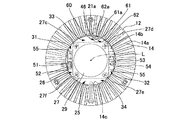
図4に示すように、筒状部10の内周側空間25、すなわち、複数の放熱フィン14で囲まれた内周側空間25には、冷却ファン26が配置されている。内周側空間25は軸線L方向から見たときに円形をしている。冷却ファン26は、全体として直方体形状をしており、軸線L方向から見た平面形状が4角形の外枠27を備えている。4角形の各辺を構成している外枠27の4枚の壁は、軸線Lと平行な外壁面を備えている。外枠27は、軸線L方向の上端部27aが空気吸い込み口28(図3参照)となっており、下端部27bが空気吹き出し口29となっている。図5に示すように、外枠27の対角線の長さ寸法は、軸線L方向から見たときに複数の放熱フィン14の内周側端部14bを繋いで形成される仮想の円14cの直径よりも僅かに短い寸法であり、外枠27の四隅は冷却フィンの内周側端部14bと僅かな隙間を開けて対向している。すなわち、冷却ファン26は、外枠27の角27c〜27fが仮想の円14cに内接するように各放熱フィン14に近接して配置されている。これにより、内周側空間25における外枠27の外周側には4つの区画31〜34が形成されている。各区画(第1区画31、第2区画32、第3区画33、第4区画34)は、複数の放熱フィン14の内周側端部14bにより形成される仮想の円14cの円弧部分と外枠27の一辺により囲まれている。
As shown in FIG. 4, a cooling
外枠27の上端部27aの四隅には、図3に示すように、冷却ファン26を固定するためのネジ穴35が設けられている。冷却ファン26は、空気吸い込み口28を上側放熱板12の放熱板貫通孔16と連通させ、上端を上側放熱板12に当接させた状態で上側放熱板12に固定されている。より具体的には、冷却ファン26は、上側放熱板12の各ファン固定用貫通孔18を上方から貫通して外枠27の各ネジ穴35に捻じ込まれる4本の有頭ネジ(不図示)によって上側放熱板12に固定されている。冷却ファン26の空気吹き出し口29は、ヒートシンク13の底板15よりも上側放熱板12の側に近い位置で、下方(LED基板5の側)を向いている。すなわち、ヒートシンク13の底板15の上面から空気吹き出し口29までの高さ寸法は、ヒートシンク13の底板15の上面から放熱フィン14の上端に至る内周側空間25の高さ寸法の1/2よりも長い(図7参照)。
As shown in FIG. 3, screw holes 35 for fixing the cooling
ここで、図3に示すように、上側放熱板12に載置された回路基板21の上面には複数の電子部品41を備える給電回路42が構成されている。給電回路42は、LED2を駆動するLED駆動回路43(第1駆動回路)、冷却ファン26を駆動する冷却ファン駆動回路44(第2駆動回路)、および、給電停止回路45を備えている。LED駆動回路43は内周側空間25の温度を検出するサーミスタ(温度検出部)46の出力に基づいてLED2への給電を制御する。冷却ファン駆動回路44は冷却ファン26を一定速度で回転させる。給電停止回路45は、給電回路42に供給される電源電流を監視しており、この電源電流が予め設定した設定値を超えた場合にLED2への給電を停止する。
Here, as shown in FIG. 3, a
回路基板21の下面には、LED駆動回路43とLED2を電気的に接続するLED用配線51を着脱可能に接続するためのLED用配線コネクタ52、冷却ファン駆動回路44と冷却ファン26を電気的に接続する冷却ファン用配線53を着脱可能に接続するための冷却ファン用配線コネクタ54、および、サーミスタ46が搭載されている。LED用配線コネクタ52、冷却ファン用配線コネクタ54およびサーミスタ46の搭載位置は、軸線L方向から見たときに、いずれも複数の放熱フィン14の内周側端部14bよりも内周側に位置している。
On the lower surface of the
LED用配線コネクタ52と冷却ファン用配線コネクタ54は、基板貫通孔22を間に挟んだ一方側および他方側にそれぞれ搭載されている。上側放熱板12には放熱板貫通孔16を間に挟んだ一方側および他方側にそれぞれコネクタ用貫通孔55が一つずつ設けられている。図4に示すように、回路基板21が上側放熱板12に載置された状態では、LED用配線コネクタ52は一方のコネクタ用貫通孔55を介して内周側空間25に突出し、冷却ファン用配線コネクタ54は他方のコネクタ用貫通孔55を介して内周側空間25に突出する。LED用配線コネクタ52および冷却ファン用配線コネクタ54の突出部分は、冷却ファン26の外枠27において平行に延びている一対の外壁部分の外周側に位置している。LED用配線コネクタ52および冷却ファン用配線コネクタ54の突出部分は、図5に示すように、内周側空間25における外枠27の外周側の4つの区画31〜34のうち、冷却ファン26を間に挟んだ両側の第1区画31と第2区画32にそれぞれ突出している。
The
図3乃至図5に示すように、LED用配線51は、LED基板5から下側放熱板11に設けられた配線貫通孔56を介して上方に引き出されている。また、配線貫通孔56を介して上方に引き出されたLED用配線51は、ヒートシンク13の底板15の側面および上面に沿って引き回されて内周側に向かって屈曲させられた後に上方に延び、冷却ファン26の外枠27と放熱フィン14の内周側端部14bの間(第1区画31)を経由してLED用配線コネクタ52に接続されている。冷却ファン用配線53は、冷却ファン26の下端部分から引き出され、冷却ファン26の外枠27と放熱フィン14の内周側端部14bの間(第2区画32)を経由して冷却ファン用配線コネクタ54に接続されている。当該構成によれば、LED用配線51および冷却ファン用配線53の双方を放熱フィン14の外周側で引き回す必要がないので、各配線51、53の納まりがよい。さらに、LED用配線51および冷却ファン用配線53を放熱フィン14の内周側端部14bよりも内周側に位置させることができるので、各配線51、53を保護することができ、照明装置1の設置に際して各配線51、53が邪魔になることがない。
As shown in FIGS. 3 to 5, the
上側放熱板12において軸線L方向から見たときにサーミスタ46と重なる位置には、図4および図5に示すように、上側放熱板12を軸線L方向に貫通するサーミスタ用貫通孔61が形成されている。サーミスタ46はこのサーミスタ用貫通孔61を介して内周側空間25に晒されている。換言すれば、回路基板21と上側放熱板12は、サーミスタ46を部分的に被う遮蔽部材60を構成している。すなわち、サーミスタ46は、回路基板21の下面においてサーミスタ46が搭載されている下面部分21aと、下面部分からサーミスタ46の側に延びてサーミスタ46を包囲するサーミスタ用貫通孔61の環状内周面61aによって部分的に囲まれている。ここで、サーミスタ46およびサーミスタ用貫通孔61は、図5に示すように、軸線L方向から見たときに冷却ファン26の外枠27と放熱フィン14の内周側端部14bの間(第3区画33)に晒されている。より具体的には、サーミスタ46およびサーミスタ用貫通孔61は、冷却ファン26の外枠27においてLED用配線コネクタ52と冷却ファン用配線コネクタ54の間に挟まれた一対の外壁部分とは異なる一対の外壁部分の外周側で、円環状に配置された複数の放熱フィン14の内周側に位置している。このような区画では、空気の対流が起こり難いので、サーミスタ46は内周側空間の温度を精度よく検出できる。
As shown in FIGS. 4 and 5, a thermistor through-
キャップ7は、図2乃至図4に示すように、軸線L方向から見た形状が円形のキャップ本体65とキャップ本体65の外周縁部分12aから下方に突出する3つの固定部66を備えている。キャップ本体65は開口62aを下方に向けた椀型である。各固定部66は軸線L回りに等角度間隔に設けられている。
As shown in FIGS. 2 to 4, the
キャップ7は放熱部6と同軸に配置されて放熱部6に固定されている。より詳細には、キャップ7は、キャップ本体65が放熱板貫通孔16、基板貫通孔22および回路基板21を上方から被い、各固定部66の下端面が上側放熱板12の外周縁部分12aの上端面に当接した状態とされて上側放熱板12に固定されている。キャップ7が放熱部6に搭載された状態では、キャップ7の外周縁と放熱部6の間に隙間67が形成されている。すなわち、周方向で各固定部66の間に位置する箇所は、キャップ本体65と上側放熱板12の間の隙間67となっている。
The
(給電回路)
図6は給電回路42のブロック図である。給電回路42は、電源ライン70を介して供給される電源電力の電源電流の電流値を監視する電流監視回路71と、電源ライン70からの電源電力の供給を受けて所定電圧の電力を出力するレギュレータ回路72を備えている。また、レギュレータ回路72から電力の供給を受けて冷却ファン26を駆動する冷却ファン制御回路73と、レギュレータ回路72から電力の供給を受けてLED2を駆動する駆動信号を出力するLED制御回路74と、駆動信号に基づいて電源ライン70からLED2に電力を供給する電力供給回路75を備えている。LED制御回路74にはサーミスタ46および電流監視回路71からの出力が入力されている。本例では、サーミスタ46として、温度の上昇に伴って抵抗値が低下するタイプのものを用いている。レギュレータ回路72、LED制御回路74および電力供給回路75はLED駆動回路43を構成している。レギュレータ回路72と冷却ファン制御回路73は冷却ファン駆動回路44を構成している。電流監視回路71、LED制御回路74および電力供給回路75は給電停止回路45を構成している。
(Power supply circuit)
FIG. 6 is a block diagram of the
LED制御回路74および電力供給回路75はLED2をPWM駆動するための回路であり、LED制御回路74は駆動信号として電力供給回路75にPWM信号を出力する。LED制御回路74は、内周側空間25の温度が上昇してサーミスタ46の抵抗値が低下し、サーミスタ46からの出力が予め設定した閾値を超えると、PWM信号のデューティ比率を低下させて、LED2へ供給される電力を低減させる。本例では、LED制御回路74は、初期状態におけるPWM信号のデューティ比率を100%とし、サーミスタ46からの出力が予め設定した閾値を超えた場合には、デューティ比率を50%へ切り換える。これによりLED制御回路74は電力供給回路75を介してLED2へ供給される電力を低減させる。一方、一旦上昇した内周側空間25の温度が下降する際などにサーミスタ46の抵抗値が上昇してサーミスタ46からの出力が閾値以下となると、LED制御回路74はPWM信号のデューティ比率を増加させる。本例では、LED2へ供給するPWM信号のデューティ比率を50%から100%へ戻す。これによりLED制御回路74は電力供給回路75を介してLED2へ供給する電力を増大させて、元に戻す。
The
また、LED制御回路74は電流監視回路71の出力に基づいてLED2への給電を制御する。本例では、電源電流が予め設定した設定値を超えると電流監視回路71から異常電流検出信号が出力される。従って、LED制御回路74は、この異常電流検出信号に基づいて駆動信号を停止する。この結果、電力供給回路75を介したLED2への給電が停止する。
The
冷却ファン制御回路73は冷却ファン26をPWM駆動する回路であり、冷却ファン26を一定速度で回転させる。
The cooling
(照明装置の動作)
図7は照明装置本体3の縦断面図である。照明装置1に電力が供給されると、LED駆動回路43を介してLED2に電力が供給され、LED2が発光する。また、冷却ファン駆動回路44を介して冷却ファン26に電力が供給され、冷却ファン26が動作する。さらに、サーミスタ46による内周側空間25の温度の検出と、電流監視回路71による電源電流の監視が開始される。照明装置1への電力供給が開始された初期状態では、LED制御回路74から電力供給回路75へ供給されるPWM信号のデューティ比率は100%である。
(Operation of lighting device)
FIG. 7 is a longitudinal sectional view of the illuminating
LED2および冷却ファン26への給電に伴い、レギュレータ回路72を搭載するLED駆動回路43および冷却ファン駆動回路44が発熱する。また、LED2の発光に伴い、LED2が発熱する。
As the
ここで、LED駆動回路43および冷却ファン駆動回路44の熱は、回路基板21から上側放熱板12を介してヒートシンク13に伝わり、放熱フィン14から放出される。LED2の熱はLED基板5から、下側放熱板11を介してヒートシンク13に伝わり、放熱フィン14から放出される。本例では、放熱フィン14を備える放熱部6がLED基板5と回路基板21の双方に当接しており、LED2を冷却するための放熱フィンと各駆動回路43、44を冷却するための放熱フィン14を別々に設ける必要がないので、簡易な構成でLED2と各駆動回路43、44からの放熱を促進できる。
Here, the heat of the
また、冷却ファン26が動作すると、図7において矢印で示すように、キャップ7の外周縁と放熱部6との間の隙間67から放熱板貫通孔16および基板貫通孔22を介して内周側空間25に吸い込まれてLED基板5の側に向かう気流Aが形成される。当該気流Aは、ヒートシンク13の底板15に衝突してその方向が変化させられ、複数の放熱フィン14の間を介して、照明装置1の外側に排出される。これにより、放熱フィン14からの放熱が促進されるので、LED駆動回路43および冷却ファン駆動回路44からの放熱とLED2からの放熱が効率よく行われる。さらに、冷却ファン26の発生させる気流Aは、回路基板21の上面を通過しているので、LED駆動回路43および冷却ファン駆動回路44はこの気流Aに晒される。従って、LED駆動回路43および冷却ファン駆動回路44からの放熱が促進される。
Further, when the cooling
次に、照明装置1の設置場所の環境温度が高温である場合などには、照明装置1の点灯が長時間に及ぶとLED2からの熱を十分に放出することができずに、LED2が過度に高温状態となることがある。このような場合には、LED基板5から下側放熱板11を介してヒートシンク13に伝わるLED2の熱が複数の放熱フィン14に囲まれた内周側空間25の温度を上昇させる。内周側空間25の温度の上昇は、サーミスタ46により検知される。
Next, when the environmental temperature of the place where the
ここで、サーミスタ46は冷却ファン26の外枠27よりも外周側で、かつ、空気吹き出し口29よりもLED基板5から離れた位置に配置されている。従って、サーミスタ46に冷却ファン26が形成する気流Aが直接吹き付けられることがなく、サーミスタ46は冷却ファン26が形成する気流Aの影響が少ない位置で内周側空間25の温度を検出できる。また、サーミスタ46は、内周側空間25に開口62aを露出させた凹部62内に配置されているので、冷却ファン26が形成する気流Aからの影響を更に排除することができる。よって、本例では、サーミスタ46からの出力に基づいてLED2の発熱状態を精度よく把握することができる。また、本例では、表面にLED駆動回路43が構成された回路基板21の下面にサーミスタ46を搭載しているので、LED駆動回路43とサーミスタ46の電気的な接続が容易である。さらに、本例では、上側放熱板12に形成したサーミスタ用貫通孔61を介してサーミスタ46を内周側空間25に晒しており、サーミスタ46を凹部62内に配置することが容易となっている。
Here, the
その後、内周側空間25の温度の上昇によりサーミスタ46の抵抗値が低下してサーミスタ46からの出力が閾値を超えると、LED制御回路74は電力供給回路75へ供給するPWM信号のデューティ比率を低下させる。本例では、PWM信号のデューティ比率を100%から50%に低下させる。これにより、LED2へ供給される電力が低減するので、LED2の発熱が抑制される。従って、自己の発熱に起因してLED2が損傷したり、LED2の寿命が短縮したりすることを防止できる。
Thereafter, when the resistance value of the
しかる後に、一旦上昇した内周側空間25の温度が下降すると、内周側空間25の温度の降下がサーミスタ46の抵抗値を上昇させる。その後、抵抗値の上昇によってサーミスタ46からの出力が閾値以下となると、LED制御回路74は電力供給回路75へ供給するPWM信号のデューティ比率を増大させる。本例では、PWM信号のデューティ比率を50%から100%に戻す。これにより、LED2には初期状態と同様の電力が供給されるようになる。
After that, when the temperature of the inner
なお、照明装置1に電力を供給している電源装置に異常が発生した場合などに照明装置1に異常な電力が供給されると、電流監視回路71によって設定値を超える電源電流が検出される。この場合には、電流監視回路71からLED駆動回路43に異常電流検出信号が入力されるので、LED制御回路74はLED2への給電を停止する。この結果、LED2に規定を超える大きな電流が流れることを防止できるので、電源装置から異常な電力が供給されたときにLED2が損傷することを防止できる。
In addition, when an abnormal power is supplied to the
本例によれば、冷却ファン26により形成される気流Aの影響を抑制しながらLED2の温度状態を把握して、LED2への給電を制御できる。これにより、LED2が過度に発熱することを回避できるので、自己の発熱に起因してLED2が損傷したり、素子の寿命が短縮したりすることを防止できる。また、異常な電源電流が検出された場合には、LED2および冷却ファン26への給電が停止されるので、照明装置1に供給される電源電力の異常によってLED2が破損することを防止できる。
According to this example, it is possible to grasp the temperature state of the
(その他の実施の形態)
上記の例では、矩形の外枠27を備える冷却ファン26を用いているが、例えば、軸線L方向から見たときに複数の放熱フィン14の内周側端部14bにより形成されている仮想の円14cの直径よりも径の小さな円形の外枠27を備える冷却ファン26を用いることができる。また、矩形以外の多角形形状の外枠27を備える冷却ファン26を用いることもできる。このような形状の外枠27を備える冷却ファン26を搭載すれば、冷却ファン26と複数の放熱フィン14の内周側端部14bとの間に空間が形成されるので、形成された空間を利用して、LED用配線51、冷却ファン用配線53を引き回すことができる。また、この空間にサーミスタ46を配置できる。
(Other embodiments)
In the above example, the cooling
また、上記の例では、サーミスタ46からの出力に基づいてLED2を駆動制御しているが、サーミスタ46からの出力に基づいて冷却ファン26を駆動制御してもよい。この場合には、例えば、内周側空間25の温度が上昇してサーミスタ46の抵抗値が低下するのに伴って、冷却ファン26の回転数を増加させる等の制御を行うことができる。
In the above example, the
さらに、照明装置1へ供給される電源電流が設定値を超えた場合には、LED2への給電とともに冷却ファン26への給電を停止するように構成することもできる。すなわち、電流監視回路71から出力される異常電流検出信号を冷却ファン制御回路73に入力し、冷却ファン制御回路73では、異常電流検出信号が入力されると冷却ファン26への給電を停止するように構成することができる。
Furthermore, when the power supply current supplied to the illuminating
また、上記の例では、内周側空間25の温度を検出するためにサーミスタ46を用いているが、サーミスタ46とは異なる温度センサを用い、当該温度センサからの出力に基づいてLED2への給電を制御することもできる。
In the above example, the
さらに、上記の例では、冷却ファン26の空気吹き出し口29がLED基板5の側を向き、空気吸い込み口28が回路基板21の側を向いているが、冷却ファン26の上下を逆にして、空気吹き出し口29が回路基板21の側を向き、空気吸い込み口28がLED基板5の側を向く状態で配置することもできる。
Furthermore, in the above example, the
このような構成によれば、冷却ファン26が動作すると、放熱フィン14の外周側から内周側空間25に吸い込まれて、放熱板貫通孔16および基板貫通孔22を介して回路基板21の上面を流れ、キャップ7の外周縁と放熱部6との間の隙間67から外側に放出される気流が形成される。当該気流によっても、放熱フィン14からの放熱が促進されるので、LED駆動回路43および冷却ファン駆動回路44からの放熱が促進される。また、当該構成においても、LED用配線51および冷却ファン用配線53を放熱フィン14の外周側で引き回す必要がないので、これらの配線の納まりがよく、配線を保護することができ、照明装置1の設置に際してこれらの配線が邪魔になることがない。さらに、当該構成においても、冷却ファン26が形成する気流がサーミスタ46に直接吹き付けられることがないので、サーミスタ46は冷却ファン26が形成する気流の影響が少ない位置で内周側空間25の温度を検出できる。
According to such a configuration, when the cooling
なお、本例では、ヒートシンク13は、板状の複数の放熱フィン14によって構成された筒状部10を備えるものであるが、環状に配列された複数本の円柱によって構成された筒状部を備えるヒートシンクを搭載することもできる。また、上記の例では、筒状部10は軸線L方向から見た輪郭が円形をしているが、多角形形状の輪郭を備えていてもよい。
In this example, the
1・・・照明装置
2・・・LED
5・・・LED基板
5a・・・LED基板の表面
5b・・・LED基板の裏面
6・・・放熱部
7・・・キャップ
10・・・筒状部
12・・・上側放熱板(放熱板)
14・・・放熱フィン
14d・・・放熱フィンの下端面(筒状部のLED基板側の端部)
14e・・・放熱フィンの上端面(筒状部の回路基板側の端部)
16・・・放熱板貫通孔
21・・・回路基板
22・・・基板貫通孔
25・・・内周側空間
26・・・冷却ファン
27・・・外枠
27a・・外枠の上端部(冷却ファンの回路基板側の端部)
27b・・外枠の下端部(冷却ファンのLED基板側の端部)
28・・・空気吸い込み口
29・・・空気吹き出し口
43・・・LED駆動回路(第1駆動回路)
44・・・冷却ファン駆動回路(第2駆動回路)
46・・・サーミスタ(温度検出部)
67・・・隙間
74・・・LED制御回路
A・・・気流
L・・・軸線
1 ...
5 ...
14 ... Radiating
14e: Upper end surface of the radiation fin (end of the cylindrical portion on the circuit board side)
16 ... Radiating plate through
27b .. Lower end of outer frame (end of cooling fan on LED board side)
28 ...
44 ... Cooling fan drive circuit (second drive circuit)
46 ... Thermistor (temperature detector)
67 ...
Claims (8)
冷却ファンと、
前記LEDを駆動する第1駆動回路および前記冷却ファンを駆動する第2駆動回路を備える回路基板と、
前記LED基板と前記回路基板との間に配置されて当該LED基板の裏面と当該回路基板の前記LED基板側の面が当接している放熱部と、を有し、
前記放熱部は、前記LED基板の厚み方向に延びる筒状部を備え、
前記冷却ファンは、前記筒状部の内周側空間内に配置されていることを特徴とする照明装置。 An LED substrate with LEDs mounted on the surface;
A cooling fan,
A circuit board comprising a first drive circuit for driving the LED and a second drive circuit for driving the cooling fan;
A heat dissipating part that is disposed between the LED board and the circuit board, and a back surface of the LED board and a surface of the circuit board on the LED board side are in contact with each other;
The heat dissipation portion includes a cylindrical portion extending in the thickness direction of the LED substrate,
The illuminating device, wherein the cooling fan is disposed in an inner circumferential space of the cylindrical portion.
前記冷却ファンは、前記回路基板側の端部および前記LED基板側の端部の一方が空気吸い込み口となっており、他方が空気吹き出し口となっている外枠を備え、
前記第1駆動回路と前記LEDとを接続する配線は、前記外枠と前記筒状部との間を経由して引き回されていることを特徴とする照明装置。 In claim 1,
The cooling fan includes an outer frame in which one of the end on the circuit board side and the end on the LED board side is an air suction port, and the other is an air blowing port,
The lighting device is characterized in that the wiring connecting the first drive circuit and the LED is routed between the outer frame and the cylindrical portion.
前記内周側空間は、前記LED基板の厚み方向から見たときに円形をしており、
前記外枠は、前記LED基板の厚み方向から見たときに多角形形状をしていることを特徴とする照明装置。 In claim 2,
The inner circumferential space has a circular shape when viewed from the thickness direction of the LED substrate,
The lighting device, wherein the outer frame has a polygonal shape when viewed from the thickness direction of the LED substrate.
前記放熱部は、前記筒状部の前記回路基板側の端部に当接する放熱板を備え、
前記冷却ファンは、前記空気吸い込み口となっている前記回路基板側の端部が前記放熱板の前記筒状部側の面に取り付けられており、
前記放熱板は、前記空気吸い込み口に連通する放熱板貫通孔を備えており、
前記回路基板は、前記放熱板貫通孔に連通する基板貫通孔を備えていることを特徴とする照明装置。 In claim 2 or 3,
The heat dissipating part includes a heat dissipating plate in contact with an end of the cylindrical part on the circuit board side,
In the cooling fan, the end on the circuit board side that is the air suction port is attached to the surface on the cylindrical portion side of the heat sink,
The heat radiating plate includes a heat radiating plate through hole communicating with the air suction port,
The circuit board includes a board through hole communicating with the heat sink through hole.
前記放熱部に固定されて前記基板貫通孔および前記回路基板を当該放熱部とは反対の側から被うキャップを備え、
前記冷却ファンは、前記キャップの外周縁と前記放熱部との間に設けられた隙間から前記放熱板貫通孔および前記基板貫通孔を介して前記内周側空間内に吸い込まれて前記LED基板に向かう気流を発生させることを特徴とする照明装置。 In claim 4,
A cap fixed to the heat dissipating part and covering the substrate through hole and the circuit board from the side opposite to the heat dissipating part;
The cooling fan is sucked into the inner peripheral space from the gap provided between the outer peripheral edge of the cap and the heat radiating portion through the heat radiating plate through hole and the substrate through hole, and into the LED substrate. An illuminating device characterized by generating an airflow to go.
前記内周側空間の温度を検出する温度検出部を有し、
前記温度検出部は、前記冷却ファンの前記外枠よりも外周側で、且つ、前記筒状部の外周よりも内側で前記空気吹き出し口よりも前記回路基板に近い側に配置されていることを特徴とする照明装置。 In any one of claims 3 to 5,
A temperature detection unit for detecting the temperature of the inner circumferential space;
The temperature detection unit is disposed on the outer peripheral side of the outer frame of the cooling fan and on the inner side of the outer periphery of the cylindrical part and closer to the circuit board than the air outlet. A lighting device.
前記第1駆動回路は、前記温度検出部の出力に基づいて前記LEDへの供給電力を制御する制御回路を備えていることを特徴とする照明装置。 In claim 6,
The first drive circuit includes a control circuit that controls power supplied to the LED based on an output of the temperature detection unit.
前記筒状部は、前記LED基板と直交する軸線回りに環状に配列された複数の放熱フィンから構成されていることを特徴とする照明装置。 In any one of claims 1 to 7,
The said cylindrical part is comprised from the several radiation fin arrange | positioned cyclically | annularly around the axis line orthogonal to the said LED board, The illuminating device characterized by the above-mentioned.
Priority Applications (1)
| Application Number | Priority Date | Filing Date | Title |
|---|---|---|---|
| JP2013124995A JP2015002027A (en) | 2013-06-13 | 2013-06-13 | Lighting device |
Applications Claiming Priority (1)
| Application Number | Priority Date | Filing Date | Title |
|---|---|---|---|
| JP2013124995A JP2015002027A (en) | 2013-06-13 | 2013-06-13 | Lighting device |
Publications (1)
| Publication Number | Publication Date |
|---|---|
| JP2015002027A true JP2015002027A (en) | 2015-01-05 |
Family
ID=52296462
Family Applications (1)
| Application Number | Title | Priority Date | Filing Date |
|---|---|---|---|
| JP2013124995A Pending JP2015002027A (en) | 2013-06-13 | 2013-06-13 | Lighting device |
Country Status (1)
| Country | Link |
|---|---|
| JP (1) | JP2015002027A (en) |
Cited By (32)
| Publication number | Priority date | Publication date | Assignee | Title |
|---|---|---|---|---|
| CN107606557A (en) * | 2017-11-10 | 2018-01-19 | 彭从文 | High heat dissipation street lamp |
| US9964266B2 (en) | 2013-07-05 | 2018-05-08 | DMF, Inc. | Unified driver and light source assembly for recessed lighting |
| USD833977S1 (en) | 2015-10-05 | 2018-11-20 | DMF, Inc. | Electrical junction box |
| US10139059B2 (en) | 2014-02-18 | 2018-11-27 | DMF, Inc. | Adjustable compact recessed lighting assembly with hangar bars |
| CN110345424A (en) * | 2018-04-02 | 2019-10-18 | 深圳市海洋王照明工程有限公司 | Downlight with radiator structure |
| USD864877S1 (en) | 2019-01-29 | 2019-10-29 | DMF, Inc. | Plastic deep electrical junction box with a lighting module mounting yoke |
| US10488000B2 (en) | 2017-06-22 | 2019-11-26 | DMF, Inc. | Thin profile surface mount lighting apparatus |
| US10551044B2 (en) | 2015-11-16 | 2020-02-04 | DMF, Inc. | Recessed lighting assembly |
| US10563850B2 (en) | 2015-04-22 | 2020-02-18 | DMF, Inc. | Outer casing for a recessed lighting fixture |
| US10591120B2 (en) | 2015-05-29 | 2020-03-17 | DMF, Inc. | Lighting module for recessed lighting systems |
| US10663153B2 (en) | 2017-12-27 | 2020-05-26 | DMF, Inc. | Methods and apparatus for adjusting a luminaire |
| US10753558B2 (en) | 2013-07-05 | 2020-08-25 | DMF, Inc. | Lighting apparatus and methods |
| USD901398S1 (en) | 2019-01-29 | 2020-11-10 | DMF, Inc. | Plastic deep electrical junction box |
| USD902871S1 (en) | 2018-06-12 | 2020-11-24 | DMF, Inc. | Plastic deep electrical junction box |
| USD905327S1 (en) | 2018-05-17 | 2020-12-15 | DMF, Inc. | Light fixture |
| US10975570B2 (en) | 2017-11-28 | 2021-04-13 | DMF, Inc. | Adjustable hanger bar assembly |
| US11060705B1 (en) | 2013-07-05 | 2021-07-13 | DMF, Inc. | Compact lighting apparatus with AC to DC converter and integrated electrical connector |
| US11067231B2 (en) | 2017-08-28 | 2021-07-20 | DMF, Inc. | Alternate junction box and arrangement for lighting apparatus |
| US11231154B2 (en) | 2018-10-02 | 2022-01-25 | Ver Lighting Llc | Bar hanger assembly with mating telescoping bars |
| US11255497B2 (en) | 2013-07-05 | 2022-02-22 | DMF, Inc. | Adjustable electrical apparatus with hangar bars for installation in a building |
| USD945054S1 (en) | 2017-06-22 | 2022-03-01 | DMF, Inc. | Light fixture |
| US11274821B2 (en) | 2019-09-12 | 2022-03-15 | DMF, Inc. | Lighting module with keyed heat sink coupled to thermally conductive trim |
| US11306903B2 (en) | 2020-07-17 | 2022-04-19 | DMF, Inc. | Polymer housing for a lighting system and methods for using same |
| US11391442B2 (en) | 2018-06-11 | 2022-07-19 | DMF, Inc. | Polymer housing for a recessed lighting system and methods for using same |
| US11435064B1 (en) | 2013-07-05 | 2022-09-06 | DMF, Inc. | Integrated lighting module |
| USD966877S1 (en) | 2019-03-14 | 2022-10-18 | Ver Lighting Llc | Hanger bar for a hanger bar assembly |
| USD970081S1 (en) | 2018-05-24 | 2022-11-15 | DMF, Inc. | Light fixture |
| US11585517B2 (en) | 2020-07-23 | 2023-02-21 | DMF, Inc. | Lighting module having field-replaceable optics, improved cooling, and tool-less mounting features |
| USD990030S1 (en) | 2020-07-17 | 2023-06-20 | DMF, Inc. | Housing for a lighting system |
| USD1012864S1 (en) | 2019-01-29 | 2024-01-30 | DMF, Inc. | Portion of a plastic deep electrical junction box |
| US12203631B2 (en) | 2020-07-16 | 2025-01-21 | DMF, Inc. | Round metal housing for a lighting system |
| US12297986B2 (en) | 2020-07-17 | 2025-05-13 | DMF, Inc. | Bar hanger assembly with crossmembers and housing assemblies using same |
-
2013
- 2013-06-13 JP JP2013124995A patent/JP2015002027A/en active Pending
Cited By (60)
| Publication number | Priority date | Publication date | Assignee | Title |
|---|---|---|---|---|
| US10753558B2 (en) | 2013-07-05 | 2020-08-25 | DMF, Inc. | Lighting apparatus and methods |
| US9964266B2 (en) | 2013-07-05 | 2018-05-08 | DMF, Inc. | Unified driver and light source assembly for recessed lighting |
| US12352405B2 (en) | 2013-07-05 | 2025-07-08 | DMF, Inc. | Adjustable electrical apparatus with hangar bars for installation in a building |
| US10982829B2 (en) | 2013-07-05 | 2021-04-20 | DMF, Inc. | Adjustable electrical apparatus with hangar bars for installation in a building |
| US12000562B2 (en) | 2013-07-05 | 2024-06-04 | DMF, Inc. | Lighting assembly with AC to DC converter and heat-sinking housing |
| US11808430B2 (en) | 2013-07-05 | 2023-11-07 | DMF, Inc. | Adjustable electrical apparatus with hangar bars for installation in a building |
| US10408395B2 (en) | 2013-07-05 | 2019-09-10 | DMF, Inc. | Recessed lighting systems |
| US11435064B1 (en) | 2013-07-05 | 2022-09-06 | DMF, Inc. | Integrated lighting module |
| US11255497B2 (en) | 2013-07-05 | 2022-02-22 | DMF, Inc. | Adjustable electrical apparatus with hangar bars for installation in a building |
| US10816148B2 (en) | 2013-07-05 | 2020-10-27 | DMF, Inc. | Recessed lighting systems |
| US11060705B1 (en) | 2013-07-05 | 2021-07-13 | DMF, Inc. | Compact lighting apparatus with AC to DC converter and integrated electrical connector |
| US11085597B2 (en) | 2013-07-05 | 2021-08-10 | DMF, Inc. | Recessed lighting systems |
| USD939134S1 (en) | 2014-02-18 | 2021-12-21 | DMF, Inc. | Module applied to a lighting assembly |
| USD907284S1 (en) | 2014-02-18 | 2021-01-05 | DMF, Inc. | Module applied to a lighting assembly |
| USD924467S1 (en) | 2014-02-18 | 2021-07-06 | DMF, Inc. | Unified casting light module |
| US11028982B2 (en) | 2014-02-18 | 2021-06-08 | DMF, Inc. | Adjustable lighting assembly with hangar bars |
| US10139059B2 (en) | 2014-02-18 | 2018-11-27 | DMF, Inc. | Adjustable compact recessed lighting assembly with hangar bars |
| US10563850B2 (en) | 2015-04-22 | 2020-02-18 | DMF, Inc. | Outer casing for a recessed lighting fixture |
| US11118768B2 (en) | 2015-04-22 | 2021-09-14 | DMF, Inc. | Outer casing for a recessed lighting fixture |
| US11435066B2 (en) | 2015-04-22 | 2022-09-06 | DMF, Inc. | Outer casing for a recessed lighting fixture |
| USD925109S1 (en) | 2015-05-29 | 2021-07-13 | DMF, Inc. | Lighting module |
| US10591120B2 (en) | 2015-05-29 | 2020-03-17 | DMF, Inc. | Lighting module for recessed lighting systems |
| US11022259B2 (en) | 2015-05-29 | 2021-06-01 | DMF, Inc. | Lighting module with separated light source and power supply circuit board |
| USD833977S1 (en) | 2015-10-05 | 2018-11-20 | DMF, Inc. | Electrical junction box |
| USD848375S1 (en) | 2015-10-05 | 2019-05-14 | DMF, Inc. | Electrical junction box |
| USD851046S1 (en) | 2015-10-05 | 2019-06-11 | DMF, Inc. | Electrical Junction Box |
| US11668455B2 (en) | 2015-11-16 | 2023-06-06 | DMF, Inc. | Casing for lighting assembly |
| US11242983B2 (en) | 2015-11-16 | 2022-02-08 | DMF, Inc. | Casing for lighting assembly |
| US10551044B2 (en) | 2015-11-16 | 2020-02-04 | DMF, Inc. | Recessed lighting assembly |
| US11649938B2 (en) | 2017-06-22 | 2023-05-16 | DMF, Inc. | Thin profile surface mount lighting apparatus |
| US11293609B2 (en) | 2017-06-22 | 2022-04-05 | DMF, Inc. | Thin profile surface mount lighting apparatus |
| US10663127B2 (en) | 2017-06-22 | 2020-05-26 | DMF, Inc. | Thin profile surface mount lighting apparatus |
| US11047538B2 (en) | 2017-06-22 | 2021-06-29 | DMF, Inc. | LED lighting apparatus with adapter bracket for a junction box |
| US10488000B2 (en) | 2017-06-22 | 2019-11-26 | DMF, Inc. | Thin profile surface mount lighting apparatus |
| USD945054S1 (en) | 2017-06-22 | 2022-03-01 | DMF, Inc. | Light fixture |
| US12169053B2 (en) | 2017-08-28 | 2024-12-17 | DMF, Inc. | Alternate junction box and arrangement for lighting apparatus |
| US11067231B2 (en) | 2017-08-28 | 2021-07-20 | DMF, Inc. | Alternate junction box and arrangement for lighting apparatus |
| CN107606557A (en) * | 2017-11-10 | 2018-01-19 | 彭从文 | High heat dissipation street lamp |
| US10975570B2 (en) | 2017-11-28 | 2021-04-13 | DMF, Inc. | Adjustable hanger bar assembly |
| US11448384B2 (en) | 2017-12-27 | 2022-09-20 | DMF, Inc. | Methods and apparatus for adjusting a luminaire |
| US10663153B2 (en) | 2017-12-27 | 2020-05-26 | DMF, Inc. | Methods and apparatus for adjusting a luminaire |
| CN110345424A (en) * | 2018-04-02 | 2019-10-18 | 深圳市海洋王照明工程有限公司 | Downlight with radiator structure |
| USD905327S1 (en) | 2018-05-17 | 2020-12-15 | DMF, Inc. | Light fixture |
| USD970081S1 (en) | 2018-05-24 | 2022-11-15 | DMF, Inc. | Light fixture |
| US11391442B2 (en) | 2018-06-11 | 2022-07-19 | DMF, Inc. | Polymer housing for a recessed lighting system and methods for using same |
| USD903605S1 (en) | 2018-06-12 | 2020-12-01 | DMF, Inc. | Plastic deep electrical junction box |
| USD902871S1 (en) | 2018-06-12 | 2020-11-24 | DMF, Inc. | Plastic deep electrical junction box |
| US11231154B2 (en) | 2018-10-02 | 2022-01-25 | Ver Lighting Llc | Bar hanger assembly with mating telescoping bars |
| USD864877S1 (en) | 2019-01-29 | 2019-10-29 | DMF, Inc. | Plastic deep electrical junction box with a lighting module mounting yoke |
| USD901398S1 (en) | 2019-01-29 | 2020-11-10 | DMF, Inc. | Plastic deep electrical junction box |
| USD1012864S1 (en) | 2019-01-29 | 2024-01-30 | DMF, Inc. | Portion of a plastic deep electrical junction box |
| USD966877S1 (en) | 2019-03-14 | 2022-10-18 | Ver Lighting Llc | Hanger bar for a hanger bar assembly |
| US11274821B2 (en) | 2019-09-12 | 2022-03-15 | DMF, Inc. | Lighting module with keyed heat sink coupled to thermally conductive trim |
| US12203631B2 (en) | 2020-07-16 | 2025-01-21 | DMF, Inc. | Round metal housing for a lighting system |
| USD990030S1 (en) | 2020-07-17 | 2023-06-20 | DMF, Inc. | Housing for a lighting system |
| US11306903B2 (en) | 2020-07-17 | 2022-04-19 | DMF, Inc. | Polymer housing for a lighting system and methods for using same |
| US12209736B2 (en) | 2020-07-17 | 2025-01-28 | DMF, Inc. | Polymer housing for a lighting system and methods for using same |
| US12297986B2 (en) | 2020-07-17 | 2025-05-13 | DMF, Inc. | Bar hanger assembly with crossmembers and housing assemblies using same |
| US11585517B2 (en) | 2020-07-23 | 2023-02-21 | DMF, Inc. | Lighting module having field-replaceable optics, improved cooling, and tool-less mounting features |
| US12372222B2 (en) | 2020-07-23 | 2025-07-29 | DMF, Inc. | Lighting module having field-replaceable optics, improved cooling, and tool-less mounting features |
Similar Documents
| Publication | Publication Date | Title |
|---|---|---|
| JP2015002027A (en) | Lighting device | |
| JP2015002028A (en) | LIGHTING DEVICE AND LIGHTING DEVICE DRIVE CONTROL METHOD | |
| JP4640313B2 (en) | LED lighting device | |
| EP2287527A1 (en) | Light emitting diode lighting device | |
| JP2011187264A (en) | Lighting system | |
| JP2010135181A (en) | Illuminating device | |
| JP2008098020A (en) | Led lighting device | |
| JP5197659B2 (en) | Lighting device | |
| JP5606381B2 (en) | Lighting device | |
| CN110914592B (en) | lighting device | |
| EP2532948A2 (en) | Lamp device | |
| KR20110004715A (en) | LED lighting unit with heat dissipation fan | |
| WO2015045494A1 (en) | Lamp | |
| JP2008210593A (en) | Illuminating device | |
| JP6471887B2 (en) | Light emitting device and lighting apparatus using the same | |
| US20140169004A1 (en) | Lamp Device and Luminaire | |
| JP2015088419A (en) | Lighting device | |
| JP2014139901A (en) | Lighting device and lighting fixture using the lighting device | |
| JP3180089U (en) | LED lighting fixture with built-in power circuit board | |
| JP5628378B1 (en) | LED lamp | |
| JP2018055794A (en) | Lighting device | |
| JP6793324B2 (en) | lighting equipment | |
| JP6861383B2 (en) | lighting equipment | |
| JP6566347B2 (en) | Lighting device | |
| JP6244776B2 (en) | lamp |