JP2014234815A - Exhaust emission control device of internal combustion engine - Google Patents
Exhaust emission control device of internal combustion engine Download PDFInfo
- Publication number
- JP2014234815A JP2014234815A JP2013119197A JP2013119197A JP2014234815A JP 2014234815 A JP2014234815 A JP 2014234815A JP 2013119197 A JP2013119197 A JP 2013119197A JP 2013119197 A JP2013119197 A JP 2013119197A JP 2014234815 A JP2014234815 A JP 2014234815A
- Authority
- JP
- Japan
- Prior art keywords
- reducing agent
- exhaust
- internal combustion
- combustion engine
- exhaust gas
- Prior art date
- Legal status (The legal status is an assumption and is not a legal conclusion. Google has not performed a legal analysis and makes no representation as to the accuracy of the status listed.)
- Granted
Links
Images


Classifications
-
- F—MECHANICAL ENGINEERING; LIGHTING; HEATING; WEAPONS; BLASTING
- F01—MACHINES OR ENGINES IN GENERAL; ENGINE PLANTS IN GENERAL; STEAM ENGINES
- F01N—GAS-FLOW SILENCERS OR EXHAUST APPARATUS FOR MACHINES OR ENGINES IN GENERAL; GAS-FLOW SILENCERS OR EXHAUST APPARATUS FOR INTERNAL-COMBUSTION ENGINES
- F01N3/00—Exhaust or silencing apparatus having means for purifying, rendering innocuous, or otherwise treating exhaust
- F01N3/08—Exhaust or silencing apparatus having means for purifying, rendering innocuous, or otherwise treating exhaust for rendering innocuous
- F01N3/10—Exhaust or silencing apparatus having means for purifying, rendering innocuous, or otherwise treating exhaust for rendering innocuous by thermal or catalytic conversion of noxious components of exhaust
- F01N3/18—Exhaust or silencing apparatus having means for purifying, rendering innocuous, or otherwise treating exhaust for rendering innocuous by thermal or catalytic conversion of noxious components of exhaust characterised by methods of operation; Control
- F01N3/20—Exhaust or silencing apparatus having means for purifying, rendering innocuous, or otherwise treating exhaust for rendering innocuous by thermal or catalytic conversion of noxious components of exhaust characterised by methods of operation; Control specially adapted for catalytic conversion
- F01N3/206—Adding periodically or continuously substances to exhaust gases for promoting purification, e.g. catalytic material in liquid form, NOx reducing agents
- F01N3/208—Control of selective catalytic reduction [SCR], e.g. by adjusting the dosing of reducing agent
-
- F—MECHANICAL ENGINEERING; LIGHTING; HEATING; WEAPONS; BLASTING
- F01—MACHINES OR ENGINES IN GENERAL; ENGINE PLANTS IN GENERAL; STEAM ENGINES
- F01N—GAS-FLOW SILENCERS OR EXHAUST APPARATUS FOR MACHINES OR ENGINES IN GENERAL; GAS-FLOW SILENCERS OR EXHAUST APPARATUS FOR INTERNAL-COMBUSTION ENGINES
- F01N2240/00—Combination or association of two or more different exhaust treating devices, or of at least one such device with an auxiliary device, not covered by indexing codes F01N2230/00 or F01N2250/00, one of the devices being
- F01N2240/20—Combination or association of two or more different exhaust treating devices, or of at least one such device with an auxiliary device, not covered by indexing codes F01N2230/00 or F01N2250/00, one of the devices being a flow director or deflector
-
- F—MECHANICAL ENGINEERING; LIGHTING; HEATING; WEAPONS; BLASTING
- F01—MACHINES OR ENGINES IN GENERAL; ENGINE PLANTS IN GENERAL; STEAM ENGINES
- F01N—GAS-FLOW SILENCERS OR EXHAUST APPARATUS FOR MACHINES OR ENGINES IN GENERAL; GAS-FLOW SILENCERS OR EXHAUST APPARATUS FOR INTERNAL-COMBUSTION ENGINES
- F01N2610/00—Adding substances to exhaust gases
- F01N2610/02—Adding substances to exhaust gases the substance being ammonia or urea
-
- F—MECHANICAL ENGINEERING; LIGHTING; HEATING; WEAPONS; BLASTING
- F01—MACHINES OR ENGINES IN GENERAL; ENGINE PLANTS IN GENERAL; STEAM ENGINES
- F01N—GAS-FLOW SILENCERS OR EXHAUST APPARATUS FOR MACHINES OR ENGINES IN GENERAL; GAS-FLOW SILENCERS OR EXHAUST APPARATUS FOR INTERNAL-COMBUSTION ENGINES
- F01N2610/00—Adding substances to exhaust gases
- F01N2610/14—Arrangements for the supply of substances, e.g. conduits
- F01N2610/1453—Sprayers or atomisers; Arrangement thereof in the exhaust apparatus
-
- Y—GENERAL TAGGING OF NEW TECHNOLOGICAL DEVELOPMENTS; GENERAL TAGGING OF CROSS-SECTIONAL TECHNOLOGIES SPANNING OVER SEVERAL SECTIONS OF THE IPC; TECHNICAL SUBJECTS COVERED BY FORMER USPC CROSS-REFERENCE ART COLLECTIONS [XRACs] AND DIGESTS
- Y02—TECHNOLOGIES OR APPLICATIONS FOR MITIGATION OR ADAPTATION AGAINST CLIMATE CHANGE
- Y02T—CLIMATE CHANGE MITIGATION TECHNOLOGIES RELATED TO TRANSPORTATION
- Y02T10/00—Road transport of goods or passengers
- Y02T10/10—Internal combustion engine [ICE] based vehicles
- Y02T10/12—Improving ICE efficiencies
Landscapes
- Chemical & Material Sciences (AREA)
- Engineering & Computer Science (AREA)
- Chemical Kinetics & Catalysis (AREA)
- Health & Medical Sciences (AREA)
- Toxicology (AREA)
- Combustion & Propulsion (AREA)
- Mechanical Engineering (AREA)
- General Engineering & Computer Science (AREA)
- Exhaust Gas After Treatment (AREA)
- Exhaust Gas Treatment By Means Of Catalyst (AREA)
Abstract
【課題】従来よりも近距離で還元剤と排気とを均一に混合できる内燃機関の排気浄化装置を提供すること。【解決手段】エンジンの排気管11に設けられた還元剤供給装置2と、還元剤供給装置2よりも下流側の排気管11に設けられた下流触媒コンバータ4と、これらの間の排気管11に設けられたミキサ3と、を備え、ミキサ3は、下流側に向かうに従い拡径する無底で中空の略円錐形状を有する第1部材31と、第1部材31の内側に第1部材31の内壁面との間に隙間を有して設けられ、下流側に向かうに従い拡径する無底で中空の、第1部材31よりも直径が小さい略円錐形状を有する第2部材32と、を備え、第1部材31及び第2部材32は、互いに同一軸線X上に設けられ、各頂点部には貫通孔310,320が形成され、還元剤供給装置2は、軸線X上から貫通孔310,320を介して還元剤を供給することを特徴とするエンジンの排気浄化装置10である。【選択図】図2An exhaust purification device for an internal combustion engine capable of uniformly mixing a reducing agent and exhaust at a shorter distance than before. A reducing agent supply device 2 provided in an exhaust pipe 11 of an engine, a downstream catalytic converter 4 provided in an exhaust pipe 11 downstream of the reducing agent supply device 2, and an exhaust pipe 11 therebetween. The mixer 3 includes a first member 31 having a bottomless, hollow, substantially conical shape whose diameter increases toward the downstream side, and a first member 31 inside the first member 31. A second member 32 having a substantially conical shape with a diameter smaller than that of the first member 31, which is provided with a gap between the inner wall surface of the first member 31 and is hollow and expands toward the downstream side. The first member 31 and the second member 32 are provided on the same axis X, and through holes 310 and 320 are formed at the respective apexes, and the reducing agent supply apparatus 2 has the through hole 310 from the axis X. 320, the reducing agent being supplied through 320, An exhaust purification device 10 down. [Selection] Figure 2
Description
本発明は、内燃機関の排気浄化装置に関する。詳しくは、内燃機関の排気通路内に供給された還元剤と排気とを混合するミキサを備えた内燃機関の排気浄化装置に関する。 The present invention relates to an exhaust emission control device for an internal combustion engine. More specifically, the present invention relates to an exhaust gas purification apparatus for an internal combustion engine including a mixer that mixes a reducing agent supplied into an exhaust passage of the internal combustion engine and exhaust gas.
従来、内燃機関(以下、「エンジン」ともいう。)の排気管内に選択還元触媒を設け、選択還元触媒の上流側の排気管から還元剤を供給することにより、NOxを浄化する技術が知られている。この技術では、通常、排気管内を流通する排気と、供給された還元剤とを混合するためのミキサが排気管内に設けられる。具体的には、例えば排気管の上流側にミキサを設け、このミキサにより旋回流を発生させることで、NH3ガス等の還元剤と排気とを混合させる技術が提案されている(例えば、特許文献1及び2参照)。
Conventionally, a technique for purifying NOx by providing a selective reduction catalyst in an exhaust pipe of an internal combustion engine (hereinafter also referred to as “engine”) and supplying a reducing agent from an exhaust pipe upstream of the selective reduction catalyst is known. ing. In this technique, usually, a mixer for mixing the exhaust flowing in the exhaust pipe and the supplied reducing agent is provided in the exhaust pipe. Specifically, for example, a technique has been proposed in which a mixer is provided on the upstream side of an exhaust pipe and a swirling flow is generated by this mixer to mix a reducing agent such as NH 3 gas and exhaust (for example, a patent)
ところで、エンジンは車両前方のエンジンルーム内に設けられ、排気管は、エンジンの排気ポートから延び、車両の床下に沿って車両の後方端部に至る。従って、排気管は、その構造上、エンジンルーム内のエンジン区間と、エンジンルーム外の床下区間とに分けられる。エンジン区間内は、エンジンからこの区間に至る排気管を流通する排気の放熱が小さく、また高温のエンジンまでの距離が短くエンジンの熱によって暖められることから、比較的高温に維持される。
ところが、エンジンルーム内には、エンジンの他、吸気系や燃料噴射系の各種装置が配置される。加えて、粒子状物質を捕集するフィルタが、捕集した粒子状物質を燃焼除去する再生処理を適宜行う必要性から、エネルギー効率が有利になるようにエンジン区間内に優先的に配置される。従って、選択還元触媒は、配置の自由度が高い床下区間内に配置される場合が多い。
By the way, the engine is provided in the engine room in front of the vehicle, and the exhaust pipe extends from the exhaust port of the engine and reaches the rear end portion of the vehicle along the under floor of the vehicle. Therefore, the exhaust pipe is divided into an engine section in the engine room and an underfloor section outside the engine room because of its structure. The engine section is maintained at a relatively high temperature because the heat from the exhaust flowing through the exhaust pipe from the engine to this section is small and the distance to the high-temperature engine is short and is warmed by the heat of the engine.
However, in addition to the engine, various devices such as an intake system and a fuel injection system are arranged in the engine room. In addition, a filter that collects particulate matter is preferentially placed in the engine section so that energy efficiency is advantageous because it is necessary to appropriately perform a regeneration process that burns and removes the collected particulate matter. . Therefore, the selective reduction catalyst is often arranged in the underfloor section having a high degree of freedom in arrangement.
しかしながら、床下区間内は、エンジン区間からこの区間に至る排気管を流通する排気の放熱が大きく、またエンジンまでの距離が長くエンジンの熱によって暖められないことから、エンジン区間よりも低温に維持される。このため、選択還元触媒の温度がNOxを還元するのに適した温度に達しない場合がある。
そこで、フィルタに選択還元触媒を担持させたうえで、このフィルタをエンジン区間内に配置することが考えられる。これにより、狭いエンジン区間内を有効に利用できるとともに、選択還元触媒に流入する排気の温度が選択還元触媒の活性温度域に早期に到達するため、NOx浄化率を改善できる。また、車両の床下に配置する排気系の各種装置が廃止され、コストを低減できる。
However, the inside of the underfloor section is maintained at a lower temperature than the engine section because the heat from the exhaust flowing through the exhaust pipe from the engine section to this section is large and the distance to the engine is long and it is not warmed by the engine heat. The For this reason, the temperature of the selective reduction catalyst may not reach a temperature suitable for reducing NOx.
Therefore, it is conceivable to place the filter in the engine section after supporting the selective reduction catalyst on the filter. As a result, the inside of the narrow engine section can be used effectively, and the temperature of the exhaust gas flowing into the selective reduction catalyst quickly reaches the activation temperature range of the selective reduction catalyst, so that the NOx purification rate can be improved. Further, various exhaust system devices disposed under the floor of the vehicle are abolished, and the cost can be reduced.
しかしながら、選択還元触媒を狭いエンジン区間内に配置した場合には、選択還元触媒とその上流側に設けられるミキサとの距離を十分に確保できない。そのため、上流側のミキサで排気の流れを形成し、還元剤と排気とを均一に混合させる技術は従来から多数あるものの、より近距離で還元剤と排気とを均一に混合させるためには、更なる改善の余地がある。 However, when the selective reduction catalyst is arranged in a narrow engine section, it is not possible to ensure a sufficient distance between the selective reduction catalyst and the mixer provided upstream thereof. Therefore, although there are many conventional techniques for forming a flow of exhaust with an upstream mixer and uniformly mixing the reducing agent and exhaust, in order to uniformly mix the reducing agent and exhaust at a shorter distance, There is room for further improvement.
本発明は上記に鑑みてなされたものであり、その目的は、従来よりも近距離で還元剤と排気とを均一に混合できる内燃機関の排気浄化装置を提供することにある。 The present invention has been made in view of the above, and an object of the present invention is to provide an exhaust purification device for an internal combustion engine that can uniformly mix a reducing agent and exhaust at a shorter distance than before.
上記目的を達成するため本発明は、内燃機関(例えば、後述のエンジン)の排気通路(例えば、後述の排気管11)に設けられ、当該排気通路内に還元剤を供給する還元剤供給手段(例えば、後述のインジェクタ20)と、当該還元剤供給手段よりも下流側の排気通路に設けられ、前記還元剤供給手段により供給された還元剤により排気を浄化する排気浄化手段(例えば、後述の下流触媒コンバータ4)と、前記還元剤供給手段と前記排気浄化手段の間の排気通路に設けられ、前記還元剤供給手段により供給された還元剤と排気とを混合するミキサ(例えば、後述のミキサ3)と、を備える内燃機関の排気浄化装置(例えば、後述の排気浄化装置10)であって、前記ミキサは、下流側に向かうに従い拡径する無底で中空の略円錐形状を有する第1部材(例えば、後述の第1部材31)と、当該第1部材の内側に前記第1部材の内壁面との間に隙間を有して設けられ、下流側に向かうに従い拡径する無底で中空の、前記第1部材よりも直径が小さい略円錐形状を有する第2部材(例えば、後述の第2部材32)と、を備え、前記第1部材及び前記第2部材は、互いに同一軸線(例えば、後述の軸線X)上に設けられるとともに、各頂点部には貫通孔(例えば、後述の貫通孔310,320)が形成され、前記還元剤供給手段は、前記軸線上から前記貫通孔を介して還元剤を供給することを特徴とする内燃機関の排気浄化装置を提供する。
In order to achieve the above object, the present invention provides a reducing agent supply means (provided in an exhaust passage (for example, an
本発明では、いずれも下流側に向かうに従い拡径する無底で中空の略円錐形状を有し、互いに直径が異なる第1部材及び第2部材により、ミキサを構成する。具体的には、第1部材よりも直径が小さい第2部材を、第1部材の内側に第1部材の内壁面との間に隙間を設けて配置し、互いに同一軸線上となるように両部材を配置する。さらには、両部材の各頂点部に貫通孔を形成し、軸線上からこれら貫通孔を介して、還元剤を供給する。
これにより、各頂点部に形成された貫通孔を介して供給された還元剤は、略円錐形状の第1部材及び第2部材を通って下流側に流入する排気によって、排気中への拡散が促進される。従って、この発明によれば、従来よりも近距離で還元剤と排気とを均一に混合できる。
In the present invention, a mixer is constituted by a first member and a second member that have a bottomless, hollow, substantially conical shape that increases in diameter toward the downstream side and have different diameters. Specifically, the second member having a diameter smaller than that of the first member is arranged with a gap between the first member and the inner wall surface of the first member, and both the two members are on the same axis. Arrange the members. Furthermore, a through-hole is formed in each vertex part of both members, and a reducing agent is supplied through these through-holes from an axial line.
As a result, the reducing agent supplied through the through-holes formed at each apex portion is diffused into the exhaust gas by the exhaust gas flowing downstream through the substantially conical first member and the second member. Promoted. Therefore, according to the present invention, the reducing agent and the exhaust gas can be uniformly mixed at a shorter distance than before.
前記第2部材の側面部には、少なくとも1つの貫通孔(例えば、後述の貫通孔321)が形成されていることが好ましい。
It is preferable that at least one through hole (for example, a through
この発明では、内側に配置された第2部材の側面部に、少なくとも1つの貫通孔を形成する。これにより、各頂点部を介して供給された還元剤は、第2部材の側面部に形成された貫通孔から流入する排気によって、排気中への拡散が促進される。従って、この発明によれば、従来よりも近距離で還元剤と排気をより均一に混合できる。
また、第2部材の側面部に貫通孔を形成することで、圧損をより低減することもできる。
In the present invention, at least one through hole is formed in the side surface of the second member disposed on the inner side. As a result, the reducing agent supplied through each apex portion is promoted to diffuse into the exhaust gas by the exhaust gas flowing in from the through hole formed in the side surface portion of the second member. Therefore, according to the present invention, the reducing agent and the exhaust gas can be mixed more uniformly at a shorter distance than before.
Moreover, a pressure loss can also be reduced more by forming a through-hole in the side part of a 2nd member.
前記第1部材の側面部には、少なくとも1つの貫通孔(例えば、後述の貫通孔311,312)が形成されていることが好ましい。
It is preferable that at least one through-hole (for example, through-
この発明では、外側に配置された第1部材の側面部に、少なくとも1つの貫通孔を形成する。これにより、各頂点部を介して供給された還元剤は、第1部材の側面部に形成された貫通孔から流入し、第2部材を通って下流側に流入する排気によって、排気中への拡散が促進される。従って、この発明によれば、従来よりも近距離で還元剤と排気をより均一に混合できる。
また、第1部材の側面部に貫通孔を形成することで、圧損をより低減することもできる。
In the present invention, at least one through hole is formed in the side surface of the first member disposed on the outside. As a result, the reducing agent supplied through each apex portion flows into the exhaust gas by the exhaust gas flowing from the through hole formed in the side surface portion of the first member and flowing downstream through the second member. Spreading is promoted. Therefore, according to the present invention, the reducing agent and the exhaust gas can be mixed more uniformly at a shorter distance than before.
Moreover, a pressure loss can also be reduced more by forming a through-hole in the side part of a 1st member.
前記第2部材の側面部に形成された貫通孔と、前記第1部材の側面部に形成された貫通孔は、前記軸線方向の下流側から見たときに互いに円周方向にずれて配置されていることが好ましい。 The through hole formed in the side surface portion of the second member and the through hole formed in the side surface portion of the first member are arranged so as to be shifted from each other in the circumferential direction when viewed from the downstream side in the axial direction. It is preferable.
この発明では、第2部材の側面部に形成した貫通孔と、第1部材の側面部に形成した貫通孔が、軸線方向の下流側から見たときに互いに円周方向にずれて配置されるように、両部材を配置する。
ここで、第2部材の側面部に形成した貫通孔と第1部材の側面部に形成した貫通孔が、軸線方向に沿った直線上にある場合には、排気が当該直線上に流れてしまう結果、両部材間への排気の流入を促進できず、両部材の側面部に貫通孔を設けたことによる還元剤の拡散促進効果が十分に得られない。これに対して、この発明によれば、両部材の側面部に形成した貫通孔同士が、軸線方向の下流側から見たときに互いに円周方向にずれているため、両部材間への排気の流入を促進できる。従って、排気中への還元剤の拡散を促進でき、従来よりも近距離で還元剤と排気とを均一に混合できる。
In this invention, the through-hole formed in the side surface portion of the second member and the through-hole formed in the side surface portion of the first member are arranged so as to be shifted from each other in the circumferential direction when viewed from the downstream side in the axial direction. Thus, both members are arranged.
Here, when the through hole formed in the side surface portion of the second member and the through hole formed in the side surface portion of the first member are on a straight line along the axial direction, the exhaust gas flows on the straight line. As a result, the inflow of exhaust gas between the two members cannot be promoted, and the effect of promoting the diffusion of the reducing agent by providing the through holes in the side surface portions of the two members cannot be sufficiently obtained. On the other hand, according to the present invention, since the through holes formed in the side surfaces of both members are displaced from each other in the circumferential direction when viewed from the downstream side in the axial direction, the exhaust between the two members is performed. Can be promoted. Therefore, diffusion of the reducing agent into the exhaust can be promoted, and the reducing agent and the exhaust can be uniformly mixed at a shorter distance than before.
前記第1部材の側面部に形成された貫通孔には、前記軸線方向の下流側から見たときに前記第2部材と重ならない位置に形成された貫通孔(例えば、後述の貫通孔312)が含まれることが好ましい。
The through hole formed in the side surface portion of the first member has a through hole formed at a position not overlapping the second member when viewed from the downstream side in the axial direction (for example, a through
この発明では、外側に配置される第1部材の側面部の貫通孔を、軸線方向の下流側から見たときに第2部材と重ならない位置にも形成する。これにより、両部材間に流入した排気を、第2部材と重ならない位置に形成された第1部材の側面部の貫通孔から流入する排気によって、排気通路の径方向中央に指向させることができる。従って、この発明によれば、排気中に均一に混合された還元剤を、下流側の排気浄化手段に効率良く供給できる。 In this invention, the through-hole of the side part of the 1st member arrange | positioned outside is formed also in the position which does not overlap with a 2nd member when it sees from the downstream of an axial direction. Thus, the exhaust gas flowing between the two members can be directed to the radial center of the exhaust passage by the exhaust gas flowing from the through hole in the side surface portion of the first member formed at a position not overlapping the second member. . Therefore, according to the present invention, the reducing agent uniformly mixed in the exhaust gas can be efficiently supplied to the exhaust gas purification means on the downstream side.
前記還元剤供給手段は、複数箇所に還元剤を供給するように構成されており、少なくとも前記第2部材の内側と、前記第1部材と前記第2部材の隙間に還元剤を供給することが好ましい。 The reducing agent supply means is configured to supply a reducing agent to a plurality of locations, and supplies the reducing agent to at least the inside of the second member and the gap between the first member and the second member. preferable.
この発明では、少なくとも、第2部材の内側と、第1部材と第2部材の隙間に還元剤を供給する。これにより、軸線上から各頂点部の貫通孔を介して、少なくとも第2部材の内側と両部材の隙間に還元剤を供給できるため、排気中への還元剤の拡散を促進でき、従来よりも近距離で還元剤と排気をより均一に混合できる。 In this invention, a reducing agent is supplied to at least the inside of the second member and the gap between the first member and the second member. Thereby, since the reducing agent can be supplied to the gap between at least the inner side of the second member and both members from the axial line through the through holes at the apexes, the diffusion of the reducing agent into the exhaust can be promoted. Reducing agent and exhaust can be mixed more uniformly at a short distance.
前記還元剤供給手段は、複数箇所に還元剤を供給するように構成されており、少なくとも前記第2部材の内側と前記第1部材の外側に還元剤を供給し、前記第1部材の外周先端部には、前記排気通路の内壁面又は前記第1部材及び第2部材を収容するケース部材(例えば、後述のケース部材33の筒状部333)の内壁面との間に隙間が形成されていることが好ましい。
The reducing agent supply means is configured to supply a reducing agent to a plurality of locations, and supplies the reducing agent to at least the inside of the second member and the outside of the first member, and the outer peripheral tip of the first member. A gap is formed between the inner wall surface of the exhaust passage or the inner wall surface of a case member (for example, a
この発明では、少なくとも、第2部材の内側と第1部材の外側に還元剤を供給する。また、第1部材の外周先端部には、排気通路の内壁面又は第1部材及び第2部材を収容するケース部材の内壁面との間に隙間を形成する。これにより、軸線上から各頂点部の貫通孔を介して、少なくとも第2部材の内側と第1部材の外側に還元剤を供給できるため、排気中への還元剤の拡散を促進でき、従来よりも近距離で還元剤と排気をより均一に混合できる。 In the present invention, the reducing agent is supplied at least to the inside of the second member and the outside of the first member. Moreover, a clearance gap is formed in the outer peripheral front-end | tip part of a 1st member between the inner wall surface of an exhaust passage or the inner wall surface of the case member which accommodates a 1st member and a 2nd member. Thereby, since the reducing agent can be supplied to at least the inner side of the second member and the outer side of the first member through the through-holes of the respective apex portions from the axial line, it is possible to promote the diffusion of the reducing agent into the exhaust gas. Even at a short distance, the reducing agent and exhaust can be mixed more uniformly.
前記第2部材の頂点部に形成された貫通孔の径は、前記第1部材の頂点部に形成された貫通孔の径よりも小さいことが好ましい。 It is preferable that the diameter of the through hole formed at the apex portion of the second member is smaller than the diameter of the through hole formed at the apex portion of the first member.
この発明では、第1部材の頂点部に形成する貫通孔の径よりも、第2部材の頂点部に形成する貫通孔の径を小さく設定する。これにより、軸線上から供給される還元剤の一部を、両部材の隙間に効率良く供給できる。従って、この発明によれば、排気中への還元剤の拡散をより促進でき、従来よりも近距離で還元剤と排気をより均一に混合できる。 In this invention, the diameter of the through hole formed at the apex portion of the second member is set smaller than the diameter of the through hole formed at the apex portion of the first member. Thereby, a part of reducing agent supplied from the axis can be efficiently supplied to the gap between the two members. Therefore, according to the present invention, the diffusion of the reducing agent into the exhaust gas can be further promoted, and the reducing agent and the exhaust gas can be mixed more uniformly at a shorter distance than before.
前記還元剤供給手段は、前記第1部材の頂点部より上流側から前記第2部材の頂点部より下流側まで前記軸線方向に沿って延設され、前記第1部材及び前記第2部材の各頂点に形成された各貫通孔に挿通される還元剤供給管(例えば、後述の第2供給管22)を含んで構成され、前記還元剤供給管は、前記軸線方向に複数の還元剤噴射口を有し、前記還元剤噴射口は、前記第1部材の外側に還元剤を噴射する第1噴射口(例えば、後述の第1噴射口221)と、前記第1部材と前記第2部材の隙間に還元剤を噴射する第2噴射口(例えば、後述の第2噴射口222)と、前記第2部材の内側に還元剤を噴射する第3噴射口(例えば、後述の第3噴射口223)と、を含んで構成されることが好ましい。
The reducing agent supply means extends along the axial direction from the upstream side of the first member to the downstream side of the second member, and includes each of the first member and the second member. A reducing agent supply pipe (for example, a
この発明では、第1部材の頂点部より上流側から第2部材の頂点部より下流側まで軸線方向に沿って延びる還元剤供給管を設け、この還元剤供給管を、両部材の各頂点に形成された各貫通孔に挿通させる。また、この還元剤供給管に、第1部材の外側に還元剤を噴射する第1噴射口と、両部材の隙間に還元剤を噴射する第2噴射口と、第2部材の内側に還元剤を噴射する第3噴射口と、を設ける。
これにより、第2部材の内側、両部材の隙間及び第1部材の外側に還元剤を供給でき、供給された還元剤を、略円錐形状の両部材を通って下流側に流入する排気によって排気中に効率良く拡散できる。従って、この発明によれば、従来よりも近距離で還元剤と排気とをより均一に混合できる。
In this invention, a reducing agent supply pipe extending along the axial direction from the upstream side of the first member to the downstream side of the second member is provided, and the reducing agent supply pipe is provided at each vertex of both members. It is made to pass through each formed through-hole. The reducing agent supply pipe has a first injection port for injecting the reducing agent to the outside of the first member, a second injection port for injecting the reducing agent into the gap between the two members, and a reducing agent on the inside of the second member. And a third injection port for injecting.
As a result, the reducing agent can be supplied to the inside of the second member, the gap between the two members, and the outside of the first member, and the supplied reducing agent is exhausted by the exhaust gas flowing downstream through both of the substantially conical members. Can diffuse efficiently inside. Therefore, according to the present invention, the reducing agent and the exhaust gas can be mixed more uniformly at a shorter distance than before.
前記還元剤は、NH3ガス又は液体還元剤に気体を混入したものであることが好ましい。 The reducing agent is preferably NH 3 gas or liquid reducing agent mixed with gas.
この発明では、還元剤として、NH3ガス又は液体還元剤に気体を混入したものを用いる。これにより、ガス状の還元剤をミキサに供給することで、上述の効果が確実に奏される。 In the present invention, NH 3 gas or liquid reducing agent mixed with gas is used as the reducing agent. Thereby, the above-mentioned effect is reliably show | played by supplying a gaseous reducing agent to a mixer.
本発明によれば、従来よりも近距離で還元剤と排気とを均一に混合できる内燃機関の排気浄化装置を提供する According to the present invention, there is provided an exhaust emission control device for an internal combustion engine capable of uniformly mixing a reducing agent and exhaust at a shorter distance than before.
以下、本発明の実施形態について、図面を参照しながら説明する。なお、第2実施形態の説明において、第1実施形態と共通する構成については同一の符号を付し、その説明を省略する。 Hereinafter, embodiments of the present invention will be described with reference to the drawings. Note that, in the description of the second embodiment, the same reference numerals are given to configurations common to the first embodiment, and the description thereof is omitted.
[第1実施形態]
図1は、本発明の第1実施形態に係る内燃機関の排気浄化装置の構成を示す図である。本実施形態に係る排気浄化装置10は、排気管11のうち、車両前方のエンジンルーム内、即ちエンジン区間内に設けられる。また、排気浄化装置10は、リーンバーン運転方式のガソリンエンジン又はディーゼルエンジンの排気浄化装置として好ましく用いられる。
[First Embodiment]
FIG. 1 is a diagram showing a configuration of an exhaust emission control device for an internal combustion engine according to a first embodiment of the present invention. The exhaust
図1に示すように、排気浄化装置10は、上流側から順に、上流触媒コンバータ1と、還元剤供給装置2と、ミキサ3と、下流触媒コンバータ4と、を備える。排気浄化装置10の上流側の排気管11は、エンジンの排気ポートから延びる排気マニホルドに接続される。
As shown in FIG. 1, the
上流触媒コンバータ1は、フロースルー型のハニカム支持体に、酸化触媒が担持されて構成される。エンジンから排出された排気に含まれるHCやCOは、この上流触媒コンバータ1を通過する過程で酸化触媒により酸化される。また、排気に含まれるNOも、上流触媒コンバータ1を通過する過程でNO2に酸化される。エンジン区間内における排気に含まれるNOxのほとんどはNOであり、NO2はほとんど含まれていない。このため、上流触媒コンバータ1でNOを酸化しNO2を生成することにより、後述する下流触媒コンバータ4に流入する排気のNO2/NOx比を、SCR触媒におけるNOx浄化性能が最適化される約0.5まで上昇させることができる。
The upstream
還元剤供給装置2は、後述するミキサ3の上流側から、還元剤としてのNH3ガスを供給するインジェクタ20を備える。インジェクタ20については、後段で詳述する。
なお、還元剤供給装置2は、NH3ガスの代わりに、尿素水等の液体還元剤に気体を混入したものを供給するように構成されてもよい。
The reducing
Note that the reducing
ミキサ3は、上述の還元剤供給装置2により供給されたNH3ガス等の還元剤と排気と混合させることで、後述の下流触媒コンバータ4に対して均一に排気中に混合された還元剤を供給する。ミキサ3については、後段で詳述する。
The
下流触媒コンバータ4は、多孔質壁で区画形成された複数のセルが上流側と下流側とで互い違いに目封じされたウォールフロー型のハニカム支持体の各セル内に、選択還元触媒(以下、「SCR触媒」という。)が担持されてなる選択還元触媒付フィルタ(以下、「SCRF」という。)から構成される。
エンジンから排出された排気に含まれる粒子状物質(以下、「PM」という)は、SCRFの多孔質壁の細孔を通過する過程で捕集される。SCRFにPMが堆積すると、背圧が増加し、燃費が悪化するおそれがある。そこで、SCRFのPM堆積量が所定量を超えた場合には、SCRFを約600℃程度まで昇温することにより、SCRFに捕集されたPMを燃焼除去するフィルタ再生処理が適宜実行される。
The downstream
Particulate matter (hereinafter referred to as “PM”) contained in the exhaust discharged from the engine is collected in the process of passing through the pores of the porous wall of the SCRF. When PM accumulates on the SCRF, the back pressure increases and the fuel consumption may deteriorate. Accordingly, when the PM deposition amount of the SCRF exceeds a predetermined amount, the filter regeneration process for burning and removing the PM collected by the SCRF is appropriately executed by raising the temperature of the SCRF to about 600 ° C.
SCRFに担持されるSCR触媒は、NH3が存在する雰囲気下で、排気中のNOxを選択的に還元する。具体的には、上述の還元剤供給装置2からNH3ガスが供給されると、下記反応式(1)〜(3)の反応が進行することで、排気中のNOxを選択的に還元する。
[化1]
NO+NO2+2NH3→2N2+3H2O ・・・反応式(1)
4NO+4NH3+O2→4N2+6H2O ・・・反応式(2)
6NO2+8NH3→7N2+12H2O ・・・反応式(3)
The SCR catalyst supported on the SCRF selectively reduces NOx in the exhaust under an atmosphere in which NH 3 exists. Specifically, when NH 3 gas is supplied from the reducing
[Chemical 1]
NO + NO 2 + 2NH 3 → 2N 2 + 3H 2 O... Reaction formula (1)
4NO + 4NH 3 + O 2 → 4N 2 + 6H 2 O ... Reaction formula (2)
6NO 2 + 8NH 3 → 7N 2 + 12H 2 O ... Reaction formula (3)
また、SCR触媒は、NH3で排気中のNOxを還元する機能を有するとともに、NH3を所定の量だけ貯蔵(ストレージ)する機能も有する。SCR触媒のNH3ストレージ量が、ストレージ可能な最大量である最大NH3ストレージ量を超えると、その下流へNH3がスリップする。このようにしてSCR触媒に貯蔵されたNH3は、還元剤供給装置2から供給されたNH3と合わせて、排気中のNOxの還元に適宜消費される。
Further, SCR catalyst has a function of reducing NOx in the exhaust in NH 3, has a function of storing NH 3 by a predetermined amount (storage). When the NH 3 storage amount of the SCR catalyst exceeds the maximum NH 3 storage amount, which is the maximum amount that can be stored, NH 3 slips downstream. The NH 3 stored in the SCR catalyst in this manner is appropriately consumed for the reduction of NOx in the exhaust gas together with the NH 3 supplied from the reducing
以下、本実施形態に係るミキサ3及びインジェクタ20について、詳しく説明する。
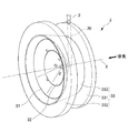
図2は、本実施形態に係るミキサ3及びインジェクタ20の斜視図である。上述したように、ミキサ3及びインジェクタ20は、上流触媒コンバータ1と下流触媒コンバータ4の間に設けられる。インジェクタ20から供給された還元剤のNH3ガスは、ミキサ3により排気と均一に混合される。
Hereinafter, the
FIG. 2 is a perspective view of the
図2に示すように、ミキサ3は、第1部材31と、第2部材32と、ケース部材33と、を含んで構成される。
第1部材31は、下流側に向かうに従い拡径し、無底で中空の略円錐形状を有する傘状の部材である。第1部材31は、後述する第2部材32の外側に配置され、第1部材の外周先端部は、第2部材32の外周先端部よりも下流側に配置される。
第1部材31の頂点部には、後述するインジェクタ20が挿通される貫通孔が形成されている。
As shown in FIG. 2, the
The
A through hole through which an
第2部材32は、第1部材31と同様に、下流側に向かうに従い拡径し、無底で中空の略円錐形状を有する傘状の部材である。第2部材32は、第1部材31と略相似形であり、その直径は第1部材31よりも小さい。第2部材32は、第1部材31と同一軸線X上に配置されるとともに、第1部材31の内側に第1部材31の内壁面との間に隙間を有して配置される。
第2部材32の頂点部には、第1部材31と同様に、後述するインジェクタ20が挿通される貫通孔が形成されている。なお、第2部材32の頂点部に形成された貫通孔と、第1部材31の頂点部に形成された貫通孔は、径が同一である。
Similar to the
Similar to the
ケース部材33は、ミキサ3を排気管11内に固定するためのものである。ケース部材33は、上流側に設けられた第1円環状部331と、下流側に設けられ第1円環状部331よりも大径の第2円環状部332と、これら円環状部を連結し第1円環状部331から第2円環状部332に向かうに従い拡径する筒状部333と、から構成される。
ただし、ケース部材33は必須の構成ではなく、ケース部材を介さずに第1部材31及び第2部材を直接、排気管11内に設けてもよい。
The
However, the
インジェクタ20は、上述の第1円環状部331内に軸線Xに対して垂直に設けられた第1供給管21と、第1供給管21から軸線X方向の下流側に延びて設けられた第2供給管22と、を含んで構成される。インジェクタ20の第2供給管22は、上述の第1部材31及び第2部材32の各頂点部に形成された貫通孔に挿通されている。
なお本実施形態では、インジェクタ20の第2供給管22は、上述の第1部材31及び第2部材32の各頂点部に形成された貫通孔に嵌合しているが、これに限定されず、隙間を設けて挿通されていてもよい。
The
In the present embodiment, the
図3は、本実施形態に係るミキサ3及びインジェクタ20を軸線X方向の下流側から見た図である。また、図4は、本実施形態に係るミキサ3及びインジェクタ20を軸線X方向の上流側から見た図である。
これら図3及び図4に示すように、外側に配置される第1部材31の側面部には、第2部材32と重なる位置に円周方向に90度間隔で配置された4つの貫通孔311と、第2部材32に重ならない位置に円周方向に90度間隔で配置された4つの貫通孔312と、が形成される。これら貫通孔311と貫通孔312は、それぞれ、円周方向の位置が互いに同一となるように形成される。
FIG. 3 is a view of the
As shown in FIG. 3 and FIG. 4, four through
また、図3及び図4に示すように、内側に配置される第2部材32の側面部には、円周方向に90度間隔で配置された4つの貫通孔321が形成される。第2部材32は、これら貫通孔321が、それぞれ、上述の第1部材31の側面部に各4つずつ形成された貫通孔311,312に対して、円周方向に45度ずれるように配置される。
As shown in FIGS. 3 and 4, four through-
図5は、図3のA−A線断面図である。図5に示すように、第1円環状部331内に軸線Xに対して垂直に設けられたインジェクタ20の第1供給管21は、第1部材31の頂点部よりも上流側に配置される。このため、第1供給管21から軸線X方向の下流側に延びて設けられた第2供給管22は、第1部材31の頂点部よりも上流側から設けられ、第2部材32の頂点部よりも下流側まで延びている。
5 is a cross-sectional view taken along line AA in FIG. As shown in FIG. 5, the
第2供給管22には、軸線X方向に複数の還元剤噴射口としての第1噴射口、第2噴射口及び第3噴射口が形成されており、第2供給管22の先端は閉塞されている。このため、還元剤は、第1部材31及び第2部材32の各頂点部に形成された貫通孔を介して、より具体的には当該貫通孔に挿通される第2供給管22を介して、複数の還元剤噴射口から排気中に供給される。
The
図6は、インジェクタ20の構成を示す断面図であり、(a)が図5のB−B線断面図であり、(b)が図5のC−C線断面図であり、(c)が図5のD−D線断面図である。図6(a)に示すように、第2供給管22のうち第1部材31の頂点部よりも上流側の位置には、断面視で円周方向に120度間隔で配置された3つの噴射口からなる第1噴射口221が形成される。これらの第1噴射口221から、第1部材31の外側に還元剤が噴射される。
なお、図5に示すように、第1部材31の外周先端部には、ケース部材33を構成する筒状部333の内壁面との間に隙間が形成され、第1部材31の外側に噴射された還元剤がこの隙間からも下流側に流れるようになっている。
6 is a cross-sectional view showing the configuration of the
As shown in FIG. 5, a gap is formed at the outer peripheral tip portion of the
また、図6(b)に示すように、第2供給管22のうち第1部材31と第2部材32の位置には、断面視で円周方向に120度間隔で配置された3つの噴射口からなる第2噴射口222が形成される。これらの第2噴射口222は、上述の第1噴射口221に対して、断面視で円周方向に60度ずれて形成される。これらの第2噴射口222から、第1部材31と第2部材32の隙間に還元剤が噴射される。より詳しくは、第1部材31の内壁面に向けて、これらの第2噴射口222から還元剤が噴射される。
Moreover, as shown in FIG.6 (b), in the position of the
また、図6(c)に示すように、第2供給管22のうち第2部材32の頂点部よりも下流側の位置には、断面視で円周方向に90度間隔で配置された4つの噴射口からなる第3噴射口223が形成される。これらの第3噴射口223から、第2部材32の内側に還元剤が噴射される。より詳しくは、第2部材32の内壁面に向けて、これらの第3噴射口223から還元剤が噴射される。
なお、これらの第3噴射口223は、上述の第1噴射口221及び第2噴射口222よりも大径に形成される。これにより、より多くの還元剤が、これらの第3噴射口223から第2部材32の内側に噴射されるようになっている。
Further, as shown in FIG. 6C, the
Note that these
以上の構成を備えるミキサ3における排気及び還元剤の流れについて、図7を参照しながら説明する。
図7は、本実施形態に係るミキサ3における排気及び還元剤の流れを示す断面図である。ここで、図7は、図5と同様に図3のA−A線断面図である。また、図7において、実線矢印は排気の流れ方向を模式的に示しており、破線矢印は還元剤の流れ方向を模式的に示している。
The flow of exhaust and reducing agent in the
FIG. 7 is a cross-sectional view showing the flow of exhaust and reducing agent in the
先ず、図7に実線矢印で示すように、上流側からミキサ3に流入する排気は、第1部材31の外壁面上に沿って流れる。このとき、第1噴射口221から第1部材31の外側に噴射された還元剤は、第1部材31の外壁面上に沿って流れる排気と混合される。
還元剤が混合された排気の一部は、第1部材31の側面部に各4つずつ形成された貫通孔311,312を通過して、第1部材31と第2部材32との間の隙間に流入する。また、第1部材31の外壁面上に沿って流れ、第1部材31の外周先端部にまで達した排気は、当該外周先端部とケース部材33を構成する筒状部333の内壁面との間に形成された隙間を通って、下流側へと流れる。
First, as indicated by solid line arrows in FIG. 7, the exhaust gas flowing into the
Part of the exhaust gas mixed with the reducing agent passes through the four through
次いで、第2噴射口222から第1部材31と第2部材32との間の隙間に噴射された還元剤は、貫通孔311,312を通過して第1部材31と第2部材32との間の隙間に流入した排気と混合される。このようにしてさらに還元剤が混合された排気は、第2部材32の外壁面上に沿って流れ、その一部は、第2部材32の側面部に形成された4つの貫通孔321を通過して、第2部材32の内側に流入する。また、第2部材32の外壁面上に沿って流れ、第2部材32の外周先端部にまで達した排気は、当該外周先端部から下流側へと流れる。
Next, the reducing agent injected from the
次いで、第3噴射口223から第2部材32の内側に噴射された還元剤は、貫通孔321を通過して第2部材32の内側に流入した排気と混合される。このとき、還元剤の流れは、貫通孔321を通過して第2部材32の内側に流入した排気によって、排気管11の径方向の中央部に指向される。
Next, the reducing agent injected from the
以上の構成を備える本実施形態に係る排気浄化装置によれば、以下の効果が奏される。
本実施形態では、いずれも下流側に向かうに従い拡径する無底で中空の略円錐形状を有し、互いに直径が異なる第1部材31及び第2部材32により、ミキサ3を構成した。具体的には、第1部材31よりも直径が小さい第2部材32を、第1部材31の内側に第1部材31の内壁面との間に隙間を設けて配置し、互いに同一軸線X上となるように両部材を配置した。さらには、両部材の各頂点部に貫通孔を形成し、軸線X上からこれら貫通孔を介して、還元剤を供給した。
これにより、各頂点部に形成された貫通孔を介して供給された還元剤は、略円錐形状の第1部材31及び第2部材32を通って下流側に流入する排気によって、排気中への拡散が促進される。従って、本実施形態によれば、従来よりも近距離で還元剤と排気とを均一に混合できる。
According to the exhaust emission control device according to the present embodiment having the above configuration, the following effects are exhibited.
In the present embodiment, the
Thereby, the reducing agent supplied through the through-holes formed in the respective apex portions flows into the exhaust gas by the exhaust gas flowing downstream through the substantially conical
本実施形態では、内側に配置された第2部材32の側面部に、4つの貫通孔321を形成した。これにより、各頂点部を介して供給された還元剤は、第2部材32の側面部に形成された4つの貫通孔321から流入する排気によって、排気中への拡散が促進される。従って、本実施形態によれば、従来よりも近距離で還元剤と排気をより均一に混合できる。また、第2部材32の側面部に4つの貫通孔321を形成することで、圧損をより低減することもできる。
In the present embodiment, four through
本実施形態では、外側に配置された第1部材31の側面部に、4つの貫通孔311と4つの貫通孔312を形成した。これにより、各頂点部を介して供給された還元剤は、第1部材31の側面部に形成された貫通孔311,312から流入し、第2部材32を通って下流側に流入する排気によって、排気中への拡散が促進される。従って、本実施形態によれば、従来よりも近距離で還元剤と排気をより均一に混合できる。また、第1部材31の側面部に貫通孔311,312を形成することで、圧損をより低減することもできる。
In the present embodiment, four through
また本実施形態では、第2部材32の側面部に形成した貫通孔321と、第1部材31の側面部に形成した貫通孔311,312が、軸線X方向の下流側から見たときに互いに円周方向にずれて配置されるように、両部材を配置した。
ここで、第2部材32の側面部に形成した貫通孔321と第1部材31の側面部に形成した貫通孔311,312が、軸線X方向に沿った直線上にある場合には、排気が当該直線上に流れてしまう結果、両部材間への排気の流入を促進できず、両部材の側面部に貫通孔を設けたことによる還元剤の拡散促進効果が十分に得られない。これに対して、本実施形態によれば、両部材の側面部に形成した貫通孔同士が、軸線X方向の下流側から見たときに互いに円周方向にずれているため、両部材間への排気の流入を促進できる。従って、排気中への還元剤の拡散を促進でき、従来よりも近距離で還元剤と排気とを均一に混合できる。
Moreover, in this embodiment, when the through-
Here, when the through
また本実施形態では、外側に配置される第1部材31の側面部の貫通孔312を、軸線X方向の下流側から見たときに第2部材32と重ならない位置にも形成する。これにより、両部材間に流入した排気を、第2部材32と重ならない位置に形成された第1部材31の側面部の貫通孔312から流入する排気によって、排気管11の径方向中央に指向させることができる。従って、本実施形態によれば、排気中に均一に混合された還元剤を、下流側の排気浄化手段に効率良く供給できる。
In the present embodiment, the through
また本実施形態では、第2部材32の内側と、第1部材31と第2部材32の隙間と、第1部材の外側に還元剤を供給した。また、第1部材31の外周先端部には、第1部材31及び第2部材32を収容するケース部材33の筒状部333の内壁面との間に隙間を形成した。
これにより、軸線X上から各頂点部の貫通孔を介して、第2部材32の内側、両部材の隙間及び第1部材31の外側に還元剤を供給できるため、排気中への還元剤の拡散を促進でき、従来よりも近距離で還元剤と排気をより均一に混合できる。
In the present embodiment, the reducing agent is supplied to the inside of the
Thereby, since the reducing agent can be supplied to the inside of the
また本実施形態では、第1部材31の頂点部より上流側から第2部材32の頂点部より下流側まで軸線X方向に沿って延びる第2供給管22を設け、この第2供給管22を、両部材の各頂点に形成された各貫通孔に挿通させた。また、この第2供給管22に、第1部材31の外側に還元剤を噴射する第1噴射口221と、両部材の隙間に還元剤を噴射する第2噴射口222と、第2部材32の内側に還元剤を噴射する第3噴射口223と、を設けた。
これにより、第2部材32の内側、両部材の隙間及び第1部材31の外側に還元剤を供給でき、供給された還元剤を、略円錐形状の両部材を通って下流側に流入する排気によって排気中に効率良く拡散できる。従って、本実施形態によれば、従来よりも近距離で還元剤と排気とをより均一に混合できる。
In the present embodiment, the
Thus, the reducing agent can be supplied to the inside of the
また本実施形態では、還元剤として、NH3ガス又は液体還元剤に気体を混入したものを用いた。これにより、ガス状の還元剤をミキサに供給することで、上述の効果が確実に奏される。 In the present embodiment, as the reducing agent, it was used as the mixed gas to the NH 3 gas or the liquid reducing agent. Thereby, the above-mentioned effect is reliably show | played by supplying a gaseous reducing agent to a mixer.
[第2実施形態]
本発明の第2実施形態に係る排気浄化装置10Aは、ミキサ3Aの構成とインジェクタ20Aの構成が第1実施形態と異なる以外は、同一の構成である。
図8は、本発明の第2実施形態に係るミキサ3A及びインジェクタ20Aの構成とその排気及び還元剤の流れを示す図である。ここで、図8は、図5及び図7と同様の方向で切断した断面図である。また、図8において、実線矢印は排気の流れ方向を模式的に示しており、破線矢印は還元剤の流れ方向を模式的に示している。
[Second Embodiment]
Exhaust gas purification apparatus 10A according to the second embodiment of the present invention has the same configuration except that the configuration of
FIG. 8 is a diagram illustrating the configuration of the
図8に示すように、本実施形態では、インジェクタ20Aの第2供給管22Aの構成が第1実施形態と相違する。具体的には、第2供給管22Aは、第1部材31の頂点部よりも上流側の位置までしか延びていない。即ち、第1部材31の頂点部に形成された貫通孔310と、第2部材32Aの頂点部に形成された貫通孔320Aには、第2供給管22Aが挿通されておらず、これら貫通孔310,320Aは露出している。
また、インジェクタ20Aの先端は開口しており、この開口部220から軸線X方向の下流側に向かって還元剤が噴射される。
As shown in FIG. 8, in the present embodiment, the configuration of the
The tip of the
また、ミキサ3Aの第2部材32の構成が第1実施形態と相違する。具体的には、第2部材32の頂点部に形成された貫通孔320Aが、第1実施形態よりも小径に形成されている。これにより、第1部材31の頂点部に形成された貫通孔310から流入した還元剤の一部が、第2部材32の外壁面上に沿って流れるように規制される。
Further, the configuration of the
以上の構成を備えるミキサ3Aにおける排気及び還元剤の流れについて、図8を参照しながら説明する。
先ず、図8に実線矢印で示すように、上流側からミキサ3Aに流入する排気は、第1部材31の外壁面上に沿って流れる。このとき、第2供給管22Aの先端の開口部220から噴射された還元剤は、第1部材31の頂点部に形成された貫通孔310を通過する他、一部は第1部材31の外壁面上に沿って排気とともに流れ、混合される。
還元剤が混合された排気の一部は、第1部材31の側面部に各4つずつ形成された貫通孔311,312を通過して、第1部材31と第2部材32との間の隙間に流入する。また、第1部材31の外壁面上に沿って流れ、第1部材31の外周先端部にまで達した排気は、当該外周先端部とケース部材33を構成する筒状部333の内壁面との間に形成された隙間を通って、下流側へと流れる。
The flow of the exhaust gas and the reducing agent in the
First, as indicated by solid line arrows in FIG. 8, the exhaust gas flowing into the
Part of the exhaust gas mixed with the reducing agent passes through the four through
次いで、第1部材31の頂点部に形成された貫通孔310を通過した還元剤は、第2部材32の頂点部に形成された貫通孔320Aを通過する他、一部は第2部材32の外壁面上に沿って流れ、第1部材31の側面部に形成された貫通孔311,312を通過した排気と混合される。このとき、第2部材32の頂点部に形成された貫通孔320Aは、第1部材31の頂点部に形成された貫通孔310よりも小径であるため、より多くの還元剤が第2部材32の外壁面上に沿う方向に指向される。
第2部材32の外壁面上に沿って流れる排気の一部は、第2部材32の側面部に形成された4つの貫通孔321を通過して、第2部材32の内側に流入する。また、第2部材32の外壁面上に沿って流れ、第2部材32の外周先端部にまで達した排気は、当該外周先端部から下流側へと流れる。
Next, the reducing agent that has passed through the through
A part of the exhaust gas flowing along the outer wall surface of the
次いで、第2部材32の頂点部に形成された貫通孔320Aを通過した還元剤は、貫通孔321を通過して第2部材32の内側に流入した排気と混合される。このとき、還元剤の流れは、貫通孔321を通過して第2部材32の内側に流入した排気によって、排気管11の径方向の中央部に指向される。
Next, the reducing agent that has passed through the through
以上の構成を備える第2実施形態に係る排気浄化装置10Aによれば、第1実施形態に係る排気浄化装置10と同様の効果が奏される。特に、第1部材31の頂点部に形成する貫通孔の径よりも、第2部材32の頂点部に形成する貫通孔の径を小さく設定することで、軸線X上から供給される還元剤の一部を、両部材の隙間に効率良く供給できる。従って、排気中への還元剤の拡散をより促進でき、従来よりも近距離で還元剤と排気をより均一に混合できる。
According to the exhaust gas purification apparatus 10A according to the second embodiment having the above configuration, the same effects as the exhaust
なお、本発明は上記実施形態に限定されるものではなく、本発明の目的を達成できる範囲での変形、改良等は本発明に含まれる。
例えば、第1部材31の側面部及び第2部材32の側面部に形成する各貫通孔の数や配置は、適宜変更可能である。
It should be noted that the present invention is not limited to the above-described embodiment, and modifications, improvements, etc. within a scope that can achieve the object of the present invention are included in the present invention.
For example, the number and arrangement of the through holes formed in the side surface of the
次に、本発明を実施例に基づいてさらに詳細に説明するが、本発明はこれに限定されるものではない。 Next, the present invention will be described in more detail based on examples, but the present invention is not limited thereto.
[実施例1]
上述の第1実施形態に係る排気浄化装置を作製した。
[Example 1]
An exhaust emission control device according to the first embodiment described above was produced.
[比較例1]
図9に示すような比較例1に係るミキサ3B及びインジェクタ20Bを備える排気浄化装置を作製した。比較例1に係るミキサ3Bは、下流側に向かうに従い拡径する筒状のケース部材33Bと、当該ケース部材33B内にインジェクタ20Bにより固定された4つのフィン31Bと、を備える。4つのフィン31Bは、隣接するフィン同士の長手方向が直交するように設けられ、それぞれ、長手方向の略中央部で下流側に向かって屈曲された形状を有する。
インジェクタ20Bは、排気管の径方向に延び互いに直交する2本の供給管から構成され、各供給管の先端部が各フィン31Bに接続される。また、各供給管の先端部には、下流側に向かって開口する噴射口が形成され、これら噴射口から還元剤が噴射されるようになっている。
[Comparative Example 1]
An exhaust emission control device including a
The
[比較例2]
図10に示すような比較例2に係るミキサ3C及びインジェクタ20Cを備える排気浄化装置を作製した。比較例2に係るミキサ3Cは、略ひし形の形状を排気の流れ方向に直交する折り軸で下流側に向かって折り曲げた形状を有するフィン31Cを備える。このフィン31Cには、複数のスリット32Cが形成される。
また、インジェクタ20Cは、上述の折り軸上に設けられ、折り軸の略中央部からフィン31Cに接続される供給管から構成される。供給管の先端部は開口しており、この開口部からフィン31Cの内側に還元剤が噴射されるようになっている。
[Comparative Example 2]
An exhaust emission control device including a
The
[評価]
実施例1及び比較1、2で作製した各排気浄化装置を、ディーゼルエンジン区間の排気管内に配置し、所定の運転条件下で排気を流入させるとともに、所定量の還元剤を供給したときのUI値を測定した。ここで、UI値とは、流れの均一性の指標として用いられるものであり、下記の数式(1)による計算により求めた。
[数1]
UI=1−Σ{|Vi−Vave|×Si/(2×Vave×S)}・・・数式(1)
上記数式(1)において、Viは流路断面を分割した各エリアにおける流速(NH3濃度)を表し、Vaveは、流路断面全体における平均流速(断面NH3濃度)を表す。また、Siは各エリアの面積を表し、Sは流路断面の総面積を表す。
[Evaluation]
The UI when the exhaust gas purification devices manufactured in Example 1 and Comparative Examples 1 and 2 are arranged in the exhaust pipe of the diesel engine section, and the exhaust gas is allowed to flow in under a predetermined operating condition and a predetermined amount of reducing agent is supplied. The value was measured. Here, the UI value is used as an index of the uniformity of the flow, and was obtained by calculation using the following formula (1).
[Equation 1]
UI = 1−Σ {| Vi−Vave | × Si / (2 × Vave × S)} Expression (1)
In the above formula (1), Vi represents the flow velocity (NH 3 concentration) in each area obtained by dividing the channel cross section, and Vave represents the average flow velocity (cross section NH 3 concentration) in the entire channel cross section. Si represents the area of each area, and S represents the total area of the flow path cross section.
図11は、実施例1、比較例1及び比較例2のUI値を示す図である。図11においてRP1はインジェクタの先端部から最も近い位置を意味しており、RP2、RP3の順にインジェクタの先端部から遠ざかっていくことを意味する。
図11に示すように、インジェクタの先端部から近距離であるRP1のみならず、RP2及びRP3いずれにおいても、実施例1は比較例1、2に比べて高いUI値が得られることが分かった。この結果から、本発明に係る排気浄化装置によれば、従来よりも近距離で還元剤と排気とを均一に混合できることが確認された。
FIG. 11 is a diagram illustrating UI values of Example 1, Comparative Example 1, and Comparative Example 2. In FIG. 11, RP1 means the position closest to the tip of the injector, and means that RP2 and RP3 move away from the tip of the injector in this order.
As shown in FIG. 11, it was found that Example 1 can obtain a higher UI value than Comparative Examples 1 and 2 not only in RP1, which is a short distance from the tip of the injector, but also in both RP2 and RP3. . From this result, it was confirmed that according to the exhaust gas purification apparatus of the present invention, the reducing agent and the exhaust gas can be uniformly mixed at a shorter distance than before.
また、実施例1と比較例2について、排気流量と背圧との関係を調べた。図12は、実施例1及び比較例2の排気流量と背圧との関係を示す図である。
図12に示すように、比較例2では、フィン31Cがその構造上、排気の流れを妨げ易い形状であるため、排気流量が大きくなるに従い、背圧が非常に高くなる。これに対して実施例1では、排気流量を大きくしても背圧はほとんど高くならないことが分かった。この結果から、本発明の排気浄化装置によれば、従来よりも圧損を低減できることが確認された。
Further, for Example 1 and Comparative Example 2, the relationship between the exhaust flow rate and the back pressure was examined. FIG. 12 is a diagram illustrating the relationship between the exhaust flow rate and the back pressure in Example 1 and Comparative Example 2.
As shown in FIG. 12, in the comparative example 2, since the
1…上流触媒コンバータ
2…還元剤供給装置(還元剤供給手段)
3…ミキサ
4…下流触媒コンバータ(排気浄化手段)
10…排気浄化装置
11…排気管(排気通路)
20…インジェクタ(還元剤供給手段)
22…第2供給管(還元剤供給管)
31…第1部材
32…第2部材
33…ケース部材
221…第1噴射口
222…第2噴射口
223…第3噴射口
310…貫通孔(第1部材の頂点部に形成された貫通孔)
311,312…貫通孔(第1部材の側面に形成された貫通孔)
321…貫通孔(第2部材の側面に形成された貫通孔)
320…貫通孔(第2部材の頂点部に形成された貫通孔)
DESCRIPTION OF
3 ...
10 ... Exhaust
20 ... Injector (reducing agent supply means)
22 ... Second supply pipe (reducing agent supply pipe)
DESCRIPTION OF
311, 312... Through hole (through hole formed in the side surface of the first member)
321 ... Through hole (through hole formed in the side surface of the second member)
320 ... through hole (through hole formed at the apex of the second member)
Claims (10)
当該還元剤供給手段よりも下流側の排気通路に設けられ、前記還元剤供給手段により供給された還元剤により排気を浄化する排気浄化手段と、
前記還元剤供給手段と前記排気浄化手段の間の排気通路に設けられ、前記還元剤供給手段により供給された還元剤と排気とを混合するミキサと、を備える内燃機関の排気浄化装置であって、
前記ミキサは、下流側に向かうに従い拡径する無底で中空の略円錐形状を有する第1部材と、当該第1部材の内側に前記第1部材の内壁面との間に隙間を有して設けられ、下流側に向かうに従い拡径する無底で中空の、前記第1部材よりも直径が小さい略円錐形状を有する第2部材と、を備え、
前記第1部材及び前記第2部材は、互いに同一軸線上に設けられるとともに、各頂点部には貫通孔が形成され、
前記還元剤供給手段は、前記軸線上から前記貫通孔を介して還元剤を供給することを特徴とする内燃機関の排気浄化装置。 A reducing agent supply means provided in the exhaust passage of the internal combustion engine for supplying the reducing agent into the exhaust passage;
An exhaust purification means that is provided in an exhaust passage downstream of the reducing agent supply means and purifies exhaust gas by the reducing agent supplied by the reducing agent supply means;
An exhaust purification device for an internal combustion engine, comprising: a mixer provided in an exhaust passage between the reducing agent supply means and the exhaust purification means, and a mixer that mixes the reducing agent supplied by the reducing agent supply means and exhaust gas. ,
The mixer has a gap between a first member having a bottomless, hollow, substantially conical shape that expands in diameter toward the downstream side, and an inner wall surface of the first member inside the first member. A second member having a substantially conical shape with a diameter smaller than that of the first member, the bottom member being hollow and expanding toward the downstream side.
The first member and the second member are provided on the same axis line, and a through hole is formed at each apex portion,
The exhaust gas purifying apparatus for an internal combustion engine, wherein the reducing agent supply means supplies the reducing agent from above the axis via the through hole.
前記第1部材の外周先端部には、前記排気通路の内壁面又は前記第1部材及び第2部材を収容するケース部材の内壁面との間に隙間が形成されていることを特徴とする請求項1から6いずれかに記載の内燃機関の排気浄化装置。 The reducing agent supply means is configured to supply a reducing agent to a plurality of locations, and supplies the reducing agent to at least the inside of the second member and the outside of the first member,
The clearance gap is formed in the outer peripheral front-end | tip part of the said 1st member between the inner wall surface of the said exhaust passage or the inner wall surface of the case member which accommodates the said 1st member and the 2nd member. Item 7. An exhaust emission control device for an internal combustion engine according to any one of Items 1 to 6.
前記還元剤供給管は、前記軸線方向に複数の還元剤噴射口を有し、
前記還元剤噴射口は、前記第1部材の外側に還元剤を噴射する第1噴射口と、前記第1部材と前記第2部材の隙間に還元剤を噴射する第2噴射口と、前記第2部材の内側に還元剤を噴射する第3噴射口と、を含んで構成されることを特徴とする請求項2から8いずれかに記載の内燃機関の排気浄化装置。 The reducing agent supply means extends along the axial direction from the upstream side of the first member to the downstream side of the second member, and includes each of the first member and the second member. It is configured to include a reducing agent supply pipe inserted into each through hole formed at the apex,
The reducing agent supply pipe has a plurality of reducing agent injection ports in the axial direction;
The reducing agent injection port includes a first injection port for injecting a reducing agent to the outside of the first member, a second injection port for injecting a reducing agent into a gap between the first member and the second member, and the first The exhaust emission control device for an internal combustion engine according to any one of claims 2 to 8, further comprising a third injection port for injecting the reducing agent inside the two members.
Priority Applications (2)
| Application Number | Priority Date | Filing Date | Title |
|---|---|---|---|
| JP2013119197A JP6076841B2 (en) | 2013-06-05 | 2013-06-05 | Exhaust gas purification device for internal combustion engine |
| DE102014205782.5A DE102014205782B4 (en) | 2013-06-05 | 2014-03-27 | Exhaust gas purification device for internal combustion engines |
Applications Claiming Priority (1)
| Application Number | Priority Date | Filing Date | Title |
|---|---|---|---|
| JP2013119197A JP6076841B2 (en) | 2013-06-05 | 2013-06-05 | Exhaust gas purification device for internal combustion engine |
Publications (2)
| Publication Number | Publication Date |
|---|---|
| JP2014234815A true JP2014234815A (en) | 2014-12-15 |
| JP6076841B2 JP6076841B2 (en) | 2017-02-08 |
Family
ID=52009199
Family Applications (1)
| Application Number | Title | Priority Date | Filing Date |
|---|---|---|---|
| JP2013119197A Expired - Fee Related JP6076841B2 (en) | 2013-06-05 | 2013-06-05 | Exhaust gas purification device for internal combustion engine |
Country Status (2)
| Country | Link |
|---|---|
| JP (1) | JP6076841B2 (en) |
| DE (1) | DE102014205782B4 (en) |
Cited By (7)
| Publication number | Priority date | Publication date | Assignee | Title |
|---|---|---|---|---|
| KR101762774B1 (en) * | 2016-03-17 | 2017-07-28 | 대지금속 주식회사 | Diffuser for engine exhaust gas purification apparatus |
| JP2017194063A (en) * | 2016-04-21 | 2017-10-26 | マン・ディーゼル・アンド・ターボ・エスイー | Mixing device for exhaust gas aftertreatment system of internal combustion engine |
| CN107407183A (en) * | 2015-03-30 | 2017-11-28 | 五十铃自动车株式会社 | Exhaust gas purifying unit |
| WO2018017139A1 (en) * | 2016-07-20 | 2018-01-25 | Faurecia Emissions Control Technologies, Usa, Llc | Flow diverter to mitigate deposits in a doser cone |
| CN108798940A (en) * | 2017-04-27 | 2018-11-13 | 福特环球技术公司 | Mixer for mixing exhaust |
| CN109236431A (en) * | 2017-07-10 | 2019-01-18 | 河北工业大学 | A kind of automobile-used SCR mixer of dismountable spiral-flow type and nozzle coupling device |
| JP2022055160A (en) * | 2020-09-28 | 2022-04-07 | 株式会社三井E&Sマシナリー | Denitration part blockage prevention device |
Families Citing this family (2)
| Publication number | Priority date | Publication date | Assignee | Title |
|---|---|---|---|---|
| FR3059710B1 (en) * | 2016-12-05 | 2020-10-30 | Aaqius & Aaqius Sa | DEVICE AND METHOD FOR INJECTING A GAS TO BE MIXED INTO AN EXHAUST LINE |
| DE102017007662A1 (en) * | 2017-08-14 | 2019-02-14 | Ruscheweyh Consult Gmbh | Exhaust system for an internal combustion engine, flange plate or bearing sleeve, exhaust manifold, vehicle and method for operating an exhaust system |
Citations (4)
| Publication number | Priority date | Publication date | Assignee | Title |
|---|---|---|---|---|
| DE102007012790A1 (en) * | 2007-03-16 | 2008-09-18 | Audi Ag | Static mixer for exhaust gas system of internal combustion engine, has carrier elements arranged around mixing axis, and flow control elements formed on carrier elements in blade-like manner, where control elements comprise slot-like notch |
| JP2009041371A (en) * | 2007-08-06 | 2009-02-26 | Bosch Corp | Exhaust emission control device and mixer unit of internal combustion engine |
| JP2011163193A (en) * | 2010-02-09 | 2011-08-25 | Honda Motor Co Ltd | Exhaust gas purifying apparatus for internal combustion engine |
| WO2013056973A1 (en) * | 2011-10-19 | 2013-04-25 | Emitec Gesellschaft Für Emissionstechnologie Mbh | Device for mixing compressed air and liquid reducing agent |
Family Cites Families (5)
| Publication number | Priority date | Publication date | Assignee | Title |
|---|---|---|---|---|
| US4054418A (en) * | 1975-11-10 | 1977-10-18 | E. I. Du Pont De Nemours And Company | Catalytic abatement system |
| KR100229731B1 (en) * | 1990-07-27 | 1999-11-15 | 브룬너 하인리히 페터 울리히 | Large diesel engine |
| JP2009121396A (en) * | 2007-11-16 | 2009-06-04 | Denso Corp | Exhaust emission control device |
| DE102008041486A1 (en) * | 2008-08-22 | 2010-02-25 | Robert Bosch Gmbh | Dosing system for inserting pollutant decreasing medium in exhaust gas, particularly for inserting reducing agent or reducing agent-precursor, has dosing module for dosing pollutant decreasing medium |
| JP2010071240A (en) * | 2008-09-19 | 2010-04-02 | Tokyo Roki Co Ltd | Exhaust gas purifying device for internal combustion engine, and swirl flow generating device |
-
2013
- 2013-06-05 JP JP2013119197A patent/JP6076841B2/en not_active Expired - Fee Related
-
2014
- 2014-03-27 DE DE102014205782.5A patent/DE102014205782B4/en not_active Expired - Fee Related
Patent Citations (4)
| Publication number | Priority date | Publication date | Assignee | Title |
|---|---|---|---|---|
| DE102007012790A1 (en) * | 2007-03-16 | 2008-09-18 | Audi Ag | Static mixer for exhaust gas system of internal combustion engine, has carrier elements arranged around mixing axis, and flow control elements formed on carrier elements in blade-like manner, where control elements comprise slot-like notch |
| JP2009041371A (en) * | 2007-08-06 | 2009-02-26 | Bosch Corp | Exhaust emission control device and mixer unit of internal combustion engine |
| JP2011163193A (en) * | 2010-02-09 | 2011-08-25 | Honda Motor Co Ltd | Exhaust gas purifying apparatus for internal combustion engine |
| WO2013056973A1 (en) * | 2011-10-19 | 2013-04-25 | Emitec Gesellschaft Für Emissionstechnologie Mbh | Device for mixing compressed air and liquid reducing agent |
Cited By (19)
| Publication number | Priority date | Publication date | Assignee | Title |
|---|---|---|---|---|
| US11149611B2 (en) | 2015-03-30 | 2021-10-19 | Isuzu Motors Limited | Exhaust purification unit |
| CN107407183B (en) * | 2015-03-30 | 2020-06-23 | 五十铃自动车株式会社 | Exhaust gas purification unit |
| CN107407183A (en) * | 2015-03-30 | 2017-11-28 | 五十铃自动车株式会社 | Exhaust gas purifying unit |
| KR101762774B1 (en) * | 2016-03-17 | 2017-07-28 | 대지금속 주식회사 | Diffuser for engine exhaust gas purification apparatus |
| KR20170120506A (en) * | 2016-04-21 | 2017-10-31 | 만 디젤 앤 터보 에스이 | Mixing apparatus for an exhaust gas aftertreatment system of an internal combustion engine |
| CN107304702B (en) * | 2016-04-21 | 2024-10-25 | 曼恩能源方案有限公司 | Mixing device for exhaust gas aftertreatment system of internal combustion engine |
| KR102271214B1 (en) * | 2016-04-21 | 2021-06-29 | 만 에너지 솔루션즈 에스이 | Mixing apparatus for an exhaust gas aftertreatment system of an internal combustion engine |
| CN107304702A (en) * | 2016-04-21 | 2017-10-31 | 曼柴油机和涡轮机欧洲股份公司 | Mixing arrangement for engine exhaust gas after-treatment system |
| JP2017194063A (en) * | 2016-04-21 | 2017-10-26 | マン・ディーゼル・アンド・ターボ・エスイー | Mixing device for exhaust gas aftertreatment system of internal combustion engine |
| WO2018017139A1 (en) * | 2016-07-20 | 2018-01-25 | Faurecia Emissions Control Technologies, Usa, Llc | Flow diverter to mitigate deposits in a doser cone |
| US10174658B2 (en) | 2016-07-20 | 2019-01-08 | Faurecia Emissions Control Technologies, Usa, Llc | Flow diverter to mitigate deposits in a doser cone |
| US11459929B2 (en) | 2016-07-20 | 2022-10-04 | Faurecia Emissions Control Technologies, Usa, Llc | Flow diverter to mitigate deposits in a doser cone |
| CN109477411A (en) * | 2016-07-20 | 2019-03-15 | 佛吉亚排放控制技术美国有限公司 | Reduce the fluid diverter of the deposit in the Tapered Cup of doser |
| CN108798940A (en) * | 2017-04-27 | 2018-11-13 | 福特环球技术公司 | Mixer for mixing exhaust |
| CN109236431A (en) * | 2017-07-10 | 2019-01-18 | 河北工业大学 | A kind of automobile-used SCR mixer of dismountable spiral-flow type and nozzle coupling device |
| JP2022055160A (en) * | 2020-09-28 | 2022-04-07 | 株式会社三井E&Sマシナリー | Denitration part blockage prevention device |
| JP7250742B2 (en) | 2020-09-28 | 2023-04-03 | 株式会社三井E&Sマシナリー | Blockage prevention device for denitrification section |
| JP2023088994A (en) * | 2020-09-28 | 2023-06-27 | 株式会社三井E&S | Blockage prevention device for denitrification section |
| JP7463587B2 (en) | 2020-09-28 | 2024-04-08 | 株式会社三井E&S | Denitrification section clogging prevention device |
Also Published As
| Publication number | Publication date |
|---|---|
| DE102014205782B4 (en) | 2017-04-13 |
| JP6076841B2 (en) | 2017-02-08 |
| DE102014205782A1 (en) | 2014-12-11 |
Similar Documents
| Publication | Publication Date | Title |
|---|---|---|
| JP6076841B2 (en) | Exhaust gas purification device for internal combustion engine | |
| US10533477B2 (en) | Integrated exhaust treatment device having compact configuration | |
| JP5120463B2 (en) | Exhaust gas purification device for internal combustion engine | |
| CN102057139B (en) | Exhaust gas purification device and exhaust gas purification system | |
| JP5985822B2 (en) | Exhaust purification device | |
| US9248404B2 (en) | Motor vehicle exhaust line | |
| US20110167810A1 (en) | Flow device for exhaust treatment system | |
| WO2013105336A1 (en) | Exhaust gas purification device | |
| JP2017214884A (en) | Exhaust purification system | |
| JP6981156B2 (en) | Exhaust purification device for internal combustion engine | |
| US8336295B2 (en) | Apparatus for reducing nitrogen oxide in exhaust pipe | |
| JP2010163988A (en) | Exhaust structure of internal combustion engine | |
| JP2010090808A (en) | Exhaust emission control device and exhaust emission control device for internal combustion engine | |
| CN111183275B (en) | Exhaust gas purification device for internal combustion engine | |
| US10603641B2 (en) | Diesel exhaust fluid mixing body using variable cross-section switchback arrangement | |
| JP2018105179A (en) | Mixer and mixer unit | |
| JP2009162122A (en) | Exhaust passage structure | |
| KR101755510B1 (en) | Device for purifying exhaust gas | |
| JP5869888B2 (en) | Exhaust purification equipment | |
| US9714597B2 (en) | Exhaust mixer for compact system | |
| JP2022135628A (en) | Exhaust emission control device for engine | |
| JP2018087497A (en) | Exhaust gas purifying apparatus |
Legal Events
| Date | Code | Title | Description |
|---|---|---|---|
| A621 | Written request for application examination |
Free format text: JAPANESE INTERMEDIATE CODE: A621 Effective date: 20151127 |
|
| A977 | Report on retrieval |
Free format text: JAPANESE INTERMEDIATE CODE: A971007 Effective date: 20160721 |
|
| A131 | Notification of reasons for refusal |
Free format text: JAPANESE INTERMEDIATE CODE: A131 Effective date: 20160802 |
|
| A521 | Request for written amendment filed |
Free format text: JAPANESE INTERMEDIATE CODE: A523 Effective date: 20160929 |
|
| TRDD | Decision of grant or rejection written | ||
| A01 | Written decision to grant a patent or to grant a registration (utility model) |
Free format text: JAPANESE INTERMEDIATE CODE: A01 Effective date: 20161213 |
|
| A61 | First payment of annual fees (during grant procedure) |
Free format text: JAPANESE INTERMEDIATE CODE: A61 Effective date: 20170111 |
|
| R150 | Certificate of patent or registration of utility model |
Ref document number: 6076841 Country of ref document: JP Free format text: JAPANESE INTERMEDIATE CODE: R150 |
|
| LAPS | Cancellation because of no payment of annual fees |