CN107407183B - Exhaust gas purification unit - Google Patents
Exhaust gas purification unit Download PDFInfo
- Publication number
- CN107407183B CN107407183B CN201680019151.9A CN201680019151A CN107407183B CN 107407183 B CN107407183 B CN 107407183B CN 201680019151 A CN201680019151 A CN 201680019151A CN 107407183 B CN107407183 B CN 107407183B
- Authority
- CN
- China
- Prior art keywords
- exhaust gas
- exhaust
- pipe
- chamber
- urea water
- Prior art date
- Legal status (The legal status is an assumption and is not a legal conclusion. Google has not performed a legal analysis and makes no representation as to the accuracy of the status listed.)
- Active
Links
Images


Classifications
-
- F—MECHANICAL ENGINEERING; LIGHTING; HEATING; WEAPONS; BLASTING
- F01—MACHINES OR ENGINES IN GENERAL; ENGINE PLANTS IN GENERAL; STEAM ENGINES
- F01N—GAS-FLOW SILENCERS OR EXHAUST APPARATUS FOR MACHINES OR ENGINES IN GENERAL; GAS-FLOW SILENCERS OR EXHAUST APPARATUS FOR INTERNAL-COMBUSTION ENGINES
- F01N3/00—Exhaust or silencing apparatus having means for purifying, rendering innocuous, or otherwise treating exhaust
- F01N3/08—Exhaust or silencing apparatus having means for purifying, rendering innocuous, or otherwise treating exhaust for rendering innocuous
- F01N3/10—Exhaust or silencing apparatus having means for purifying, rendering innocuous, or otherwise treating exhaust for rendering innocuous by thermal or catalytic conversion of noxious components of exhaust
- F01N3/18—Exhaust or silencing apparatus having means for purifying, rendering innocuous, or otherwise treating exhaust for rendering innocuous by thermal or catalytic conversion of noxious components of exhaust characterised by methods of operation; Control
- F01N3/20—Exhaust or silencing apparatus having means for purifying, rendering innocuous, or otherwise treating exhaust for rendering innocuous by thermal or catalytic conversion of noxious components of exhaust characterised by methods of operation; Control specially adapted for catalytic conversion
- F01N3/206—Adding periodically or continuously substances to exhaust gases for promoting purification, e.g. catalytic material in liquid form, NOx reducing agents
- F01N3/208—Control of selective catalytic reduction [SCR], e.g. by adjusting the dosing of reducing agent
-
- F—MECHANICAL ENGINEERING; LIGHTING; HEATING; WEAPONS; BLASTING
- F01—MACHINES OR ENGINES IN GENERAL; ENGINE PLANTS IN GENERAL; STEAM ENGINES
- F01N—GAS-FLOW SILENCERS OR EXHAUST APPARATUS FOR MACHINES OR ENGINES IN GENERAL; GAS-FLOW SILENCERS OR EXHAUST APPARATUS FOR INTERNAL-COMBUSTION ENGINES
- F01N3/00—Exhaust or silencing apparatus having means for purifying, rendering innocuous, or otherwise treating exhaust
- F01N3/08—Exhaust or silencing apparatus having means for purifying, rendering innocuous, or otherwise treating exhaust for rendering innocuous
- F01N3/10—Exhaust or silencing apparatus having means for purifying, rendering innocuous, or otherwise treating exhaust for rendering innocuous by thermal or catalytic conversion of noxious components of exhaust
- F01N3/18—Exhaust or silencing apparatus having means for purifying, rendering innocuous, or otherwise treating exhaust for rendering innocuous by thermal or catalytic conversion of noxious components of exhaust characterised by methods of operation; Control
- F01N3/20—Exhaust or silencing apparatus having means for purifying, rendering innocuous, or otherwise treating exhaust for rendering innocuous by thermal or catalytic conversion of noxious components of exhaust characterised by methods of operation; Control specially adapted for catalytic conversion
- F01N3/206—Adding periodically or continuously substances to exhaust gases for promoting purification, e.g. catalytic material in liquid form, NOx reducing agents
- F01N3/2066—Selective catalytic reduction [SCR]
-
- B—PERFORMING OPERATIONS; TRANSPORTING
- B01—PHYSICAL OR CHEMICAL PROCESSES OR APPARATUS IN GENERAL
- B01D—SEPARATION
- B01D53/00—Separation of gases or vapours; Recovering vapours of volatile solvents from gases; Chemical or biological purification of waste gases, e.g. engine exhaust gases, smoke, fumes, flue gases, aerosols
- B01D53/34—Chemical or biological purification of waste gases
- B01D53/92—Chemical or biological purification of waste gases of engine exhaust gases
- B01D53/94—Chemical or biological purification of waste gases of engine exhaust gases by catalytic processes
-
- F—MECHANICAL ENGINEERING; LIGHTING; HEATING; WEAPONS; BLASTING
- F01—MACHINES OR ENGINES IN GENERAL; ENGINE PLANTS IN GENERAL; STEAM ENGINES
- F01N—GAS-FLOW SILENCERS OR EXHAUST APPARATUS FOR MACHINES OR ENGINES IN GENERAL; GAS-FLOW SILENCERS OR EXHAUST APPARATUS FOR INTERNAL-COMBUSTION ENGINES
- F01N3/00—Exhaust or silencing apparatus having means for purifying, rendering innocuous, or otherwise treating exhaust
- F01N3/08—Exhaust or silencing apparatus having means for purifying, rendering innocuous, or otherwise treating exhaust for rendering innocuous
- F01N3/10—Exhaust or silencing apparatus having means for purifying, rendering innocuous, or otherwise treating exhaust for rendering innocuous by thermal or catalytic conversion of noxious components of exhaust
- F01N3/24—Exhaust or silencing apparatus having means for purifying, rendering innocuous, or otherwise treating exhaust for rendering innocuous by thermal or catalytic conversion of noxious components of exhaust characterised by constructional aspects of converting apparatus
- F01N3/28—Construction of catalytic reactors
- F01N3/2892—Exhaust flow directors or the like, e.g. upstream of catalytic device
-
- F—MECHANICAL ENGINEERING; LIGHTING; HEATING; WEAPONS; BLASTING
- F01—MACHINES OR ENGINES IN GENERAL; ENGINE PLANTS IN GENERAL; STEAM ENGINES
- F01N—GAS-FLOW SILENCERS OR EXHAUST APPARATUS FOR MACHINES OR ENGINES IN GENERAL; GAS-FLOW SILENCERS OR EXHAUST APPARATUS FOR INTERNAL-COMBUSTION ENGINES
- F01N2240/00—Combination or association of two or more different exhaust treating devices, or of at least one such device with an auxiliary device, not covered by indexing codes F01N2230/00 or F01N2250/00, one of the devices being
- F01N2240/20—Combination or association of two or more different exhaust treating devices, or of at least one such device with an auxiliary device, not covered by indexing codes F01N2230/00 or F01N2250/00, one of the devices being a flow director or deflector
-
- F—MECHANICAL ENGINEERING; LIGHTING; HEATING; WEAPONS; BLASTING
- F01—MACHINES OR ENGINES IN GENERAL; ENGINE PLANTS IN GENERAL; STEAM ENGINES
- F01N—GAS-FLOW SILENCERS OR EXHAUST APPARATUS FOR MACHINES OR ENGINES IN GENERAL; GAS-FLOW SILENCERS OR EXHAUST APPARATUS FOR INTERNAL-COMBUSTION ENGINES
- F01N2240/00—Combination or association of two or more different exhaust treating devices, or of at least one such device with an auxiliary device, not covered by indexing codes F01N2230/00 or F01N2250/00, one of the devices being
- F01N2240/40—Combination or association of two or more different exhaust treating devices, or of at least one such device with an auxiliary device, not covered by indexing codes F01N2230/00 or F01N2250/00, one of the devices being a hydrolysis catalyst
-
- F—MECHANICAL ENGINEERING; LIGHTING; HEATING; WEAPONS; BLASTING
- F01—MACHINES OR ENGINES IN GENERAL; ENGINE PLANTS IN GENERAL; STEAM ENGINES
- F01N—GAS-FLOW SILENCERS OR EXHAUST APPARATUS FOR MACHINES OR ENGINES IN GENERAL; GAS-FLOW SILENCERS OR EXHAUST APPARATUS FOR INTERNAL-COMBUSTION ENGINES
- F01N2610/00—Adding substances to exhaust gases
- F01N2610/02—Adding substances to exhaust gases the substance being ammonia or urea
-
- Y—GENERAL TAGGING OF NEW TECHNOLOGICAL DEVELOPMENTS; GENERAL TAGGING OF CROSS-SECTIONAL TECHNOLOGIES SPANNING OVER SEVERAL SECTIONS OF THE IPC; TECHNICAL SUBJECTS COVERED BY FORMER USPC CROSS-REFERENCE ART COLLECTIONS [XRACs] AND DIGESTS
- Y02—TECHNOLOGIES OR APPLICATIONS FOR MITIGATION OR ADAPTATION AGAINST CLIMATE CHANGE
- Y02T—CLIMATE CHANGE MITIGATION TECHNOLOGIES RELATED TO TRANSPORTATION
- Y02T10/00—Road transport of goods or passengers
- Y02T10/10—Internal combustion engine [ICE] based vehicles
- Y02T10/12—Improving ICE efficiencies
Landscapes
- Engineering & Computer Science (AREA)
- Chemical & Material Sciences (AREA)
- Chemical Kinetics & Catalysis (AREA)
- Combustion & Propulsion (AREA)
- General Engineering & Computer Science (AREA)
- Health & Medical Sciences (AREA)
- Mechanical Engineering (AREA)
- Toxicology (AREA)
- Biomedical Technology (AREA)
- Environmental & Geological Engineering (AREA)
- Analytical Chemistry (AREA)
- General Chemical & Material Sciences (AREA)
- Oil, Petroleum & Natural Gas (AREA)
- Exhaust Gas After Treatment (AREA)
Abstract
Description
技术领域technical field
本发明涉及包括SCR催化剂的排气净化单元。The present invention relates to an exhaust gas purification unit including an SCR catalyst.
背景技术Background technique
作为还原净化从内燃机排出的排气中的氮氧化物(NOx)的排气净化单元,已知其包括:前级部,其包括氧化催化剂或捕集排气中的微粒状物质(以下,称为PM)的过滤器;以及后级部,其包括将从尿素水生成的氨作为还原剂来净化排气中的氮氧化物(以下,称为NOx)的选择性还原催化剂(以下,称为SCR催化剂)(例如,参照专利文献1、2)。As an exhaust purification unit for reducing and purifying nitrogen oxides (NOx) in exhaust gas discharged from an internal combustion engine, it is known to include a pre-stage section including an oxidation catalyst or trapping particulate matter in exhaust gas (hereinafter, referred to as a filter for PM); and a rear stage including a selective reduction catalyst (hereinafter, referred to as NOx) that purifies nitrogen oxides (hereinafter, referred to as NOx) in exhaust gas by using ammonia generated from urea water as a reducing agent SCR catalyst) (for example, refer to Patent Documents 1 and 2).
在专利文献1所记载的排气净化单元中,容纳氧化催化剂和过滤器的前级外壳与容纳SCR催化剂的后级外壳并列,在前级外壳的出口和后级外壳的入口分别连接有被配置于前级外壳与后级外壳之间的直线状配管的上游端及下游端。在配管的上游端配置有尿素水喷射装置,通过向被从前级外壳导入到后级外壳的排气气体中添加尿素水,尿素水在排气气体中被水解而生成氨,并将该氨作为还原剂供给到SCR催化剂中,从而还原净化排气气体中的NOx。In the exhaust gas purification unit described in Patent Document 1, a front-stage casing that houses an oxidation catalyst and a filter is arranged in parallel with a rear-stage casing that houses an SCR catalyst. The upstream and downstream ends of the linear piping between the front-stage casing and the rear-stage casing. A urea water injection device is arranged at the upstream end of the piping, and by adding urea water to the exhaust gas introduced from the front-stage casing to the rear-stage casing, the urea water is hydrolyzed in the exhaust gas to generate ammonia, and the ammonia is used as the The reducing agent is supplied to the SCR catalyst, thereby reducing and purifying NOx in the exhaust gas.
在专利文献2所记载的排气净化单元中,在比尿素水的喷射位置靠上游侧的位置,设置有使排气气体回旋的产生回旋流用的叶片,作为回旋流的排气气体和被喷射的尿素水在配管内被混合。In the exhaust purification unit described in Patent Document 2, a blade for generating a swirling flow is provided at a position upstream of the injection position of the urea water, and the exhaust gas and the injected swirling flow are provided with a blade for swirling the exhaust gas. The urea water is mixed in the piping.
现有技术文献prior art literature
专利文献Patent Literature
专利文献1:日本特开2009-36109号公报Patent Document 1: Japanese Patent Laid-Open No. 2009-36109
专利文献2:日本特开2006-29233号公报Patent Document 2: Japanese Patent Laid-Open No. 2006-29233
发明内容SUMMARY OF THE INVENTION
发明要解决的课题The problem to be solved by the invention
尿素水被从配管的上游端附近向下游侧喷射,相对于此,排气气体相对于排气气体的流动交叉地被从前级壳体向配管的上游端导入。因此,被喷射的尿素水的一部分在扩散前被排气气体冲向配管的上游部的壁面并附着。因此,由于尿素水的水解效率恶化、以及在被供给到SCR催化剂的排气气体中的氨的扩散性降低,从而使SCR催化剂的排气气体净化能力降低。The urea water is injected from the vicinity of the upstream end of the piping to the downstream side, and the exhaust gas is introduced from the front-stage casing to the upstream end of the piping so as to intersect the flow of the exhaust gas. Therefore, a part of the injected urea water is swept toward the wall surface of the upstream portion of the pipe by the exhaust gas and adheres to it before being diffused. Therefore, due to the deterioration of the hydrolysis efficiency of the urea water and the reduction of the diffusivity of ammonia in the exhaust gas supplied to the SCR catalyst, the exhaust gas purification capability of the SCR catalyst is reduced.
本公开的排气净化单元的目的在于,通过提高尿素水水解的效率,并提高在排气气体中的氨的扩散性,从而提高催化剂的排气气体净化能力。The purpose of the exhaust gas purification unit of the present disclosure is to improve the exhaust gas purification capability of the catalyst by improving the efficiency of hydrolysis of urea water and improving the diffusivity of ammonia in the exhaust gas.
用于解决课题的手段means of solving problems
本公开的排气净化单元包括:选择还原型催化剂,其被设置于内燃机的排气系统中,并将氨作为还原剂来选择还原排气中的氮氧化物,排气管,其向上述选择还原型催化剂中输送排气气体,尿素水喷射装置,其被配置为与上述排气管的排气上游端相对,并向上述排气管内喷射尿素水,送气室,其将容纳催化剂的壳体的排气下游端和上述排气管的排气上游端连接,并形成使排气气体从上述壳体向上述排气管折回地流动的流路,以及整流部件,其被设置于上述送气室中,为从上述尿素水喷射装置的喷射口附近向上述排气管一边逐渐扩径一边延伸的圆锥台形状的管材,形成有多个通气口,在各通气口的每一个上设有将排气气体向排气下游侧引导的引导部。The exhaust gas purification unit of the present disclosure includes: a selective reduction type catalyst which is provided in the exhaust system of the internal combustion engine and uses ammonia as a reducing agent to selectively reduce nitrogen oxides in the exhaust gas; A reduction-type catalyst conveys exhaust gas, a urea water injection device, which is arranged to face the exhaust upstream end of the above-mentioned exhaust pipe and injects urea water into the above-mentioned exhaust pipe, and a plenum chamber, which will accommodate a casing of the catalyst The exhaust downstream end of the exhaust pipe is connected to the exhaust upstream end of the exhaust pipe to form a flow path for the exhaust gas to flow back from the casing to the exhaust pipe, and a rectifying member is provided in the air supply chamber Among them, a plurality of air vents are formed in a pipe material in a truncated cone shape extending from the vicinity of the injection port of the urea water injection device to the exhaust pipe while gradually expanding its diameter, and each air port is provided with an exhaust port. A guide portion that guides the gas to the downstream side of the exhaust gas.
此外,本公开的排气净化单元包括:选择还原型催化剂,其被设置于内燃机的排气系统中,并将氨作为还原剂来选择还原排气中的氮氧化物,排气管,其向上述选择还原型催化剂中输送排气气体,尿素水喷射装置,其向上述排气管内喷射尿素水,排气导入部,其被连接于上述排气管上,并形成有多个通气口;上述排气管包括从上述尿素水喷射装置被喷射尿素水的内管、以及和该内管共同形成双层管构造的外管,且在上述内管的内侧以及上述内管与上述外管之间形成有排气气体的流路;上述排气导入部被连接于上述内管的排气上游端,被以从上述尿素水喷射装置的喷射口附近到上述内管的排气上游端一边逐渐扩径一边延伸的方式形成为圆锥台形状。Further, the exhaust gas purification unit of the present disclosure includes a selective reduction type catalyst provided in an exhaust system of an internal combustion engine and selectively reducing nitrogen oxides in the exhaust gas using ammonia as a reducing agent, an exhaust pipe, which is directed to the exhaust gas. The above-mentioned selective reduction type catalyst conveys exhaust gas, a urea water injection device, which injects urea water into the above-mentioned exhaust pipe, an exhaust gas introduction part, which is connected to the above-mentioned exhaust pipe and is formed with a plurality of vents; the above-mentioned The exhaust pipe includes an inner pipe to which urea water is injected from the urea water injection device, and an outer pipe that forms a double-pipe structure together with the inner pipe, inside the inner pipe and between the inner pipe and the outer pipe A flow path of the exhaust gas is formed; the exhaust gas introduction part is connected to the exhaust gas upstream end of the inner pipe, and is gradually expanded from the vicinity of the injection port of the urea water injection device to the exhaust gas upstream end of the inner pipe. It is formed in the shape of a truncated cone so that one side of the diameter extends.
发明效果Invention effect
根据本公开的排气净化单元,通过提高尿素水水解的效率,并提高在排气气体中的氨的扩散性,从而能够提高催化剂的排气气体净化能力。According to the exhaust gas purification unit of the present disclosure, by improving the efficiency of hydrolysis of urea water and improving the diffusivity of ammonia in the exhaust gas, the exhaust gas purification capability of the catalyst can be improved.
附图的简要说明Brief Description of Drawings
图1是表示一个实施方式的排气净化单元的立体图。FIG. 1 is a perspective view showing an exhaust gas purification unit according to an embodiment.
图2是表示混合室及连接配管的内部的剖视图。FIG. 2 is a cross-sectional view showing the inside of a mixing chamber and connecting piping.
图3是表示在混合室内的排气气体的流动的图。FIG. 3 is a diagram showing the flow of exhaust gas in a mixing chamber.
图4是表示在混合室内的排气气体的流动的图。FIG. 4 is a diagram showing the flow of exhaust gas in the mixing chamber.
图5是表示其它实施方式的整流部的剖视图。FIG. 5 is a cross-sectional view showing a rectifying portion according to another embodiment.
图6是表示其它实施方式的整流部的剖视图。FIG. 6 is a cross-sectional view showing a rectifying portion according to another embodiment.
图7是表示其它实施方式的整流部的剖视图。FIG. 7 is a cross-sectional view showing a rectifying portion according to another embodiment.
图8是表示其它实施方式的整流部的剖视图。FIG. 8 is a cross-sectional view showing a rectifying portion according to another embodiment.
图9是表示其它实施方式的混合室及连接配管的内部的剖视图。9 is a cross-sectional view showing the inside of a mixing chamber and a connecting pipe according to another embodiment.
图10是表示其它实施方式的在混合室内及连接配管内的排气气体的流动的图。FIG. 10 is a diagram showing the flow of exhaust gas in the mixing chamber and in the connecting pipe according to another embodiment.
具体实施方式Detailed ways
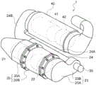
以下,参照附图说明本公开的一个实施方式。图1是表示一个实施方式的排气净化单元1的立体图。如该图所示,排气净化单元1从排气上游侧起按顺序包括:前级壳体20、混合室23、尿素水喷射阀30、连接配管24、以及后级壳体40。Hereinafter, one embodiment of the present disclosure will be described with reference to the accompanying drawings. FIG. 1 is a perspective view showing an exhaust gas purification unit 1 according to an embodiment. As shown in the figure, the exhaust purification unit 1 includes a front-
前级壳体20和后级壳体40为圆筒状,以两者的轴线相互平行的方式并列,并由配置于两者间的连接配管24来连接。连接配管24包括圆筒状的第1配管24A,该配管24A的轴线被配置为与前级壳体20及后级壳体40的轴线平行。The front-
前级壳体20包括:第1壳体20A;以及第2壳体20B,其被同轴地配置于第1壳体20A的排气下游侧。在第1壳体20A的排气下游端与第2壳体20B的排气上游端上设有环状的法兰,两法兰由螺栓、螺母连结。此外,在第1壳体20A中,容纳有第1氧化催化剂21,并且在第2壳体20B中,容纳有过滤器22。The front-
第1氧化催化剂21例如是在堇青石蜂窝结构体等陶瓷制承载体表面承载有催化剂成分等的催化剂。第1氧化催化剂21氧化通过远后喷射或排气管喷射供给的未燃烃(HC)来使排气温度上升。The
过滤器22例如是将由多孔质性的分隔壁划分的多个单元沿着排气的流动方向配置,并将这些单元的上游侧和下游侧交替地孔封闭的过滤器。过滤器22在分隔壁的细孔或表面捕集排气中的微粒状物质(以下,称为PM),并且,PM堆积推定量达到预定量并实施所谓的过滤器强制再生,则燃烧除去PM。在此,过滤器强制再生是通过由排气管喷射或远后喷射向排气上游侧的第1氧化催化剂21供给未燃烃,并使流入到过滤器22中的排气温度升温到PM燃烧温度从而进行的。The
混合室23包括:第1腔室23A,其被配置于第2壳体20B的排气下游端,侧面为圆弧状;以及第2腔室23B,其从第1腔室23A的侧面延伸到后级壳体40侧,侧面为圆弧状。第1腔室23A被配置为与第2壳体20B同轴。此外,第2腔室23B的直径比第1腔室23A的直径小,两者的边界呈圆弧状弯曲。The
在第2壳体20B的排气下游端和第1腔室23A的排气上游端上设有环状的法兰,两法兰由螺栓、螺母来连结。An annular flange is provided on the exhaust downstream end of the
连接配管24包括:圆筒状的第1配管24A,其被连接于第2腔室23B;以及第2配管24B,其连接该第1配管24A和后级壳体40的排气上游端。第1配管24A被配置为与尿素水喷射阀30的喷射轴同轴。The
第2配管24B是弯头管,排气下游端被形成为圆盘状。该第2配管24B的直线部被配置为与第1配管24A同轴,在第1配管24A的排气下游端和第2配管24B的排气上游端上设有环状的法兰,两法兰由螺栓、螺母来连结。此外,在第2配管24B的排气下游端和后级壳体40的排气上游端上设有环状的法兰,两法兰由螺栓、螺母来连结。The
尿素水喷射阀30被设置于第2腔室23B上。该尿素水喷射阀30的喷射轴被与连接配管24的轴心对齐,从尿素水喷射阀30向连接配管24的排气下游侧喷射(喷雾)尿素水。The urea
在连接配管24内,从尿素水喷射阀30喷射的尿素水以及从混合室23向后级壳体40流动的排气气体被混合,尿素水由排气热而被水解从而生成氨(NH3)。生成的氨通过排气气体的流动被供给到排气下游侧的SCR催化剂41。In the connecting
在后级壳体40中,容纳有SCR催化剂41、以及被配置于SCR催化剂41的排气下游侧的第2氧化催化剂42。The rear-
SCR催化剂41例如是在多孔质陶瓷承载体上承载有沸石等的催化剂。SCR催化剂41使从尿素水喷射阀30供给的作为还原剂的氨吸附,并且,用吸附的氨有选择地从通过的排气中还原净化NOx。The
第2氧化催化剂42例如是在堇青石蜂窝结构体等陶瓷制承载体表面承载有催化剂成分等的催化剂,并具有氧化从SCR催化剂41向排气下游侧泄漏的氨的功能。The
图2是表示混合室23及连接配管24的内部的剖视图。如该图所示,在混合室23的第2腔室23B内,设有整流部51,在整流部51中,设有整流部件50。整流部件50为两端开口的圆锥台形状的管材,被配置为与尿素水喷射阀30同轴。FIG. 2 is a cross-sectional view showing the inside of the mixing
整流部件50的小径的开口50A被配置为与尿素水喷射阀30的喷射口相对,且整流部件50的大径的开口50B的一部分被插入在连接配管24的上游端内。在整流部件50的开口50B的缘部外周面与连接配管24的上游端内周面之间,留有供排气气体通过的间隙。The
整流部件50为多孔部件,矩形状的小孔50C以狭窄的间隔被形成在周向及轴向上。在此,小孔50C通过切起弯曲加工而形成,爪50D以小孔50C的上游侧作为起点向整流部件50的内侧弯折。爪50D的切起弯曲的角度为锐角,爪50D作为将通过了小孔50C的排气气体向排气下游侧引导的引导部发挥作用。The rectifying
图3及图4是表示在混合室23内的排气气体的流动的图。如图3所示,由于从第1腔室23A到第2腔室23B,流路的宽度变窄,并且,一侧(图中左侧)的侧壁弯曲并凹陷,从而从第1腔室23A流动到第2腔室23B中的排气气体产生回旋流。3 and 4 are diagrams showing the flow of the exhaust gas in the mixing
而且,如图4所示,成为了回旋流的排气气体通过整流部件50的外侧而向连接配管24内流动,或者,通过小孔50C和整流部件50内而向连接配管24内流动。在连接配管24内,排气气体一边绕连接配管24的轴心回旋,一边向下游侧流动。Then, as shown in FIG. 4 , the swirling exhaust gas flows into the connecting
在此,尿素水喷射阀30将尿素水向整流部件50内喷射。被喷射(喷雾)的尿素水由于整流部件50从上游侧到下游侧扩径,此外,还由于从小孔50C流入的排气气体被爪50D向排气下游侧引导,从而被扩散。而且,被扩散了的尿素水与成为了回旋流的排气气体在连接配管24内混合。Here, the urea
由此,能够在使向连接配管24内喷射(喷雾)的尿素水扩散之后与成为了回旋流的排气气体混合,能够防止尿素水由于排气气体的流动而附着于第2腔室23B或连接配管24的壁面。因此,能够提高尿素水的水解效率。As a result, the urea water sprayed (sprayed) into the connecting
在此,在尿素水附着于壁面的情况下,尽管该尿素水也会由排气气体或壁面的热而被水解,但是在连接配管24内的氨的扩散性降低。对此,在本实施方式的整流部51中,由于能够防止尿素水向第2腔室23B或连接配管24的壁面附着,因此能够将均匀地扩散有氨的回旋流的排气气体向SCR催化剂41供给,从而能够提高SCR催化剂41的排气气体净化能力。Here, when the urea water adheres to the wall surface, the urea water is also hydrolyzed by the heat of the exhaust gas or the wall surface, but the diffusibility of ammonia in the connecting
图5是表示其它实施方式的整流部151的剖视图。另外,对于与上述的实施方式同样的构成标注相同的附图标记,并省略说明。如图5所示,整流部151包括:整流部件50;以及撞击板混合器152,其被配置于整流部件50的排气下游侧。撞击板混合器152在圆环状的框架上设有丝网(省略图示)和扩散板152A。撞击板混合器152在整流部件50的下游端附近被面对开口50B地配置。FIG. 5 is a cross-sectional view showing a rectifying
在上述构成的整流部151中,从尿素水喷射阀30喷射并由整流部件50扩散了的尿素水撞击到撞击板混合器152的丝网。由此,尿素水的水解被促进。而且,尿素水及通过水解产生的氨由扩散板152A进一步扩散并向连接配管24流动。In the
因此,与包括上述整流部51的排气净化单元相比,由于能够进一步提高尿素水的水解效率,从而能够进一步提高SCR催化剂41的排气气体净化能力。Therefore, since the hydrolysis efficiency of urea water can be further improved, the exhaust gas purification capability of the
图6是表示其它实施方式的整流部251的剖视图。另外,对于与上述的实施方式同样的构成标注相同的附图标记,并省略说明。如图6所示,整流部251包括:整流部件50;以及水解催化剂252,其被配置于整流部件50的排气下游侧。作为水解催化剂252,能够使用例如在氮化硅制的蜂巢或金属蜂巢的壁面上承载有氧化钛的水解催化剂、或在堇青石蜂巢的壁面上承载有氧化铝的水解催化剂等。水解催化剂252在整流部件50的下游端附近被面对开口50B地配置。FIG. 6 is a cross-sectional view showing a rectifying
在上述构成的整流部251中,从尿素水喷射阀30喷射并由整流部件50扩散了的尿素水通过水解催化剂252。此时,尿素水的水解被促进。而且,尿素水及通过水解产生的氨由成为了回旋流的排气气体向连接配管24的排气下游侧输送。In the rectifying
因此,与包括上述整流部51的排气净化单元相比,由于能够进一步提高尿素水的水解效率,从而能够进一步提高SCR催化剂41的排气气体净化能力。Therefore, since the hydrolysis efficiency of urea water can be further improved, the exhaust gas purification capability of the
图7是表示其它实施方式的整流部351的剖视图。另外,对于与上述的实施方式同样的构成标注相同的附图标记,并省略说明。如图7所示,在整流部351中,设有整流部件350。整流部件350为两端开口的圆锥台形状的管材,被配置为与尿素水喷射阀30同轴。FIG. 7 is a cross-sectional view showing a rectifying
整流部件350的小径的开口350A被配置为与尿素水喷射阀30的喷射口相对,整流部件350的大径的开口350B被配置为与连接配管24的上游端相对。在整流部件350的开口350B的缘部与连接配管24的上游端及第2腔室23B之间,留有供排气气体通过的间隙。The
整流部件350为多孔部件,通过将金属蜂巢成型为圆锥台形状而形成,在周向及轴向上以狭窄的间隔形成有矩形状的小孔350C。在此,金属蜂巢的分隔壁350D被配置为相对于金属蜂巢的厚度方向倾斜,并相对整流部件350的轴心平行。由此,分隔壁350D作为将通过了小孔350C的排气气体向排气下游侧引导的引导部发挥作用。The rectifying
在上述构成的整流部351中,与上述整流部51同样,被喷射(喷雾)的尿素水由于整流部件350从上游侧到下游侧扩径,此外,还由于从小孔350C流入的排气气体由分隔壁350D向排气下游侧引导,从而被扩散。而且,扩散了的尿素水与成为了回旋流的排气气体在连接配管24内混合。In the rectifying
图8是表示其它实施方式的整流部451的剖视图。另外,对于与上述的实施方式同样的构成标注相同的附图标记,并省略说明。如图8所示,整流部451包括:整流部件350;以及水解催化剂252,其被配置于整流部件350的排气下游侧。FIG. 8 is a cross-sectional view showing a rectifying
在上述构成的整流部451中,与上述整流部251同样,从尿素水喷射阀30喷射并由整流部件350扩散了的尿素水通过水解催化剂252。此时,尿素水的水解被促进。而且,尿素水及通过水解产生的氨由成为了回旋流的排气气体向连接配管24的排气下游侧输送。In the rectifying
图9是表示其它实施方式的混合室23及连接配管24的内部的剖视图。另外,对于与上述的实施方式同样的构成标注相同的附图标记,并省略说明。如图9所示,本实施方式的连接配管24的第1配管24A为双层管构造,包括:圆筒状的外管24C,其从第1配管24A的排气上游端到排气下游端呈直线状延伸;以及圆筒状的内管24D,其从第1配管24A的排气上游端向排气下游侧呈直线状延伸。内管24D被设置于整流部件50的下游侧。在本实施例中,内管24D的排气上游端与整流部件50的排气下游端同径,两者被接合。由此,在整流部件50的外侧流过的排气气体通过外管24C与内管24D之间而向排气下游侧流动。FIG. 9 is a cross-sectional view showing the inside of the mixing
在内管24D的排气上游侧的部分中未设有开口,在该部分中排气气体不会在内管24D的内外之间出入。另一方面,在内管24D的排气下游侧的部分中,在周向及轴向上以狭窄的间隔形成有多个小孔24E,排气气体在内管24D的内外之间出入。No opening is provided in the portion of the
图10是表示在混合室23及连接配管24内的排气气体的流动的图。如该图所示,成为了回旋流的排气气体在整流部件50的外侧通过而向连接配管24的外管24C与内管24D之间流动,或者,通过小孔50C和整流部件50内而向连接配管24内流动。在连接配管24内,排气气体一边绕连接配管24的轴心回旋,一边向下游侧流动。在外管24C与内管24D之间流动的排气气体在双层管构造部分中的排气下游侧通过小孔24E流入到内管24D内。FIG. 10 is a diagram showing the flow of the exhaust gas in the mixing
需要说明的是,尿素水喷射阀30将尿素水向整流部件50内喷射。被喷射(喷雾)的尿素水由于整流部件50从上游侧到下游侧扩径,此外,还由于从小孔50C流入的排气气体由爪50D向排气下游侧引导,从而被扩散。而且,扩散了的尿素水与成为了回旋流的排气气体在连接配管24内混合。由此,能够在使向连接配管24内喷射(喷雾)的尿素水扩散之后与成为了回旋流的排气气体混合。It should be noted that the urea
在此,在连接配管24内,通过排气气体在外管24C与内管24D之间流动,从而加热在内管24D内流动的排气气体。由此,能够抑制排气气体的温度因尿素水被水解时的潜热而降低,并提高从尿素水向氨的转化效率,由此,能够提高在SCR催化剂41中的NOx净化率。Here, in the connecting
此外,由于能够防止尿素水因排气气体的流动而附着于第2腔室23A或连接配管24的壁面,从而能够提高尿素水的水解效率,此外,还能够提高在连接配管24内的氨的扩散性。In addition, since the urea water can be prevented from adhering to the wall surface of the
进而,由于在双层管构造部分中的排气下游侧,在外管24C与内管24D之间流动的排气气体流入到内管24D内,并与扩散有氨或者尿素水的排气气体混合,从而能够进一步提高排气气体中的氨的扩散性。Further, the exhaust gas flowing between the
在上述实施方式中,说明了将具有双层管构造的第1配管24A的内管24D设置于整流部件50的下游侧的例子。同样,也可以将具有双层管构造的第1配管24A的内管24D设置于整流部件350的下游侧。In the above-described embodiment, the example in which the
另外,本公开不应限定于上述的实施方式,能够在不脱离本公开的主旨的范围内适当变形而实施。In addition, this disclosure should not be limited to the above-mentioned embodiment, It can deform|transform suitably in the range which does not deviate from the summary of this disclosure, and can implement.
本申请基于2015年03月30日申请的日本专利申请(特愿2015-068050)、及2015年04月20日申请的日本专利申请(特愿2015-085716),并将其内容作为参照援引于此。This application is based on Japanese Patent Application No. 2015-068050 filed on March 30, 2015 and Japanese Patent Application No. 2015-085716 filed on April 20, 2015, the contents of which are incorporated herein by reference. this.
工业实用性Industrial Applicability
本公开的排气净化单元在通过提高尿素水的水解效率,并提高在排气气体中的氨的扩散性,从而能够提高催化剂的排气气体净化能力这一点上有用。The exhaust gas purification unit of the present disclosure is useful in that the exhaust gas purification capability of the catalyst can be improved by improving the hydrolysis efficiency of the urea water and improving the diffusivity of ammonia in the exhaust gas.
附图标记说明Description of reference numerals
1排气净化单元、20前级壳体、20A第1壳体、20B第2壳体、21第1氧化催化剂、22过滤器、23混合室、23A第1腔室、23B第2腔室、24连接配管、24A第1配管、24B第2配管、24C外管、24D内管、24E小孔、30尿素水喷射阀、40后级壳体、41 SCR催化剂、42第2氧化催化剂、50整流部件、50A开口、50B开口、50C小孔、50D爪、51整流部、151整流部、152撞击板混合器、152A扩散板、251整流部、252水解催化剂、350整流部件、350A开口、350B开口、350C小孔、350D分隔壁、351整流部、451整流部1 exhaust purification unit, 20 pre-stage case, 20A first case, 20B second case, 21 first oxidation catalyst, 22 filter, 23 mixing chamber, 23A first chamber, 23B second chamber, 24 connecting piping, 24A first piping, 24B second piping, 24C outer pipe, 24D inner pipe, 24E small hole, 30 urea water injection valve, 40 post-stage casing, 41 SCR catalyst, 42 second oxidation catalyst, 50 rectifier Parts, 50A opening, 50B opening, 50C small hole, 50D claw, 51 rectification part, 151 rectification part, 152 impact plate mixer, 152A diffuser plate, 251 rectification part, 252 hydrolysis catalyst, 350 rectification part, 350A opening, 350B opening , 350C small hole, 350D partition wall, 351 rectifier, 451 rectifier
Claims (6)
Applications Claiming Priority (5)
| Application Number | Priority Date | Filing Date | Title |
|---|---|---|---|
| JP2015068050A JP2016188579A (en) | 2015-03-30 | 2015-03-30 | Exhaust purification unit |
| JP2015-068050 | 2015-03-30 | ||
| JP2015085716A JP2016205188A (en) | 2015-04-20 | 2015-04-20 | Exhaust emission control unit |
| JP2015-085716 | 2015-04-20 | ||
| PCT/JP2016/060217 WO2016158993A1 (en) | 2015-03-30 | 2016-03-29 | Exhaust purification unit |
Publications (2)
| Publication Number | Publication Date |
|---|---|
| CN107407183A CN107407183A (en) | 2017-11-28 |
| CN107407183B true CN107407183B (en) | 2020-06-23 |
Family
ID=57005775
Family Applications (1)
| Application Number | Title | Priority Date | Filing Date |
|---|---|---|---|
| CN201680019151.9A Active CN107407183B (en) | 2015-03-30 | 2016-03-29 | Exhaust gas purification unit |
Country Status (4)
| Country | Link |
|---|---|
| US (1) | US11149611B2 (en) |
| EP (1) | EP3279440B1 (en) |
| CN (1) | CN107407183B (en) |
| WO (1) | WO2016158993A1 (en) |
Families Citing this family (17)
| Publication number | Priority date | Publication date | Assignee | Title |
|---|---|---|---|---|
| CN106368773B (en) * | 2016-08-30 | 2019-03-29 | 潍柴动力股份有限公司 | A kind of engine and its double-cyclone mixing arrangement |
| GB2557651B (en) * | 2016-12-14 | 2019-08-21 | Perkins Engines Co Ltd | Pipe mixer for an aftertreatment system |
| US10533478B2 (en) | 2017-12-12 | 2020-01-14 | Faurecia Emissions Control Technologies, Usa, Llc | Mixer and valve assembly |
| DE102018103368A1 (en) | 2018-02-15 | 2019-08-22 | Man Truck & Bus Ag | Device for mixing exhaust gas and an additive |
| US10767536B2 (en) * | 2018-03-27 | 2020-09-08 | Cnh Industrial America Llc | Efficient mixing of gases in an exhaust aftertreatment system |
| US10287948B1 (en) | 2018-04-23 | 2019-05-14 | Faurecia Emissions Control Technologies, Usa, Llc | High efficiency mixer for vehicle exhaust system |
| US10316721B1 (en) | 2018-04-23 | 2019-06-11 | Faurecia Emissions Control Technologies, Usa, Llc | High efficiency mixer for vehicle exhaust system |
| WO2020049085A1 (en) * | 2018-09-06 | 2020-03-12 | Cnh Industrial Italia S.P.A. | Improved after treatment system for a vehicle |
| NL2021665B1 (en) * | 2018-09-19 | 2020-05-07 | Daf Trucks Nv | A mixer for an engine exhaust system |
| US10787946B2 (en) | 2018-09-19 | 2020-09-29 | Faurecia Emissions Control Technologies, Usa, Llc | Heated dosing mixer |
| FI128516B (en) | 2019-05-24 | 2020-06-30 | Proventia Oy | A mixer arrangement and a method of mixing for aftertreatment of exhaust gas |
| EP3792462A1 (en) | 2019-09-13 | 2021-03-17 | Donaldson Company, Inc. | Dosing and mixing assemblies for exhaust aftertreatment system |
| EP3812557B1 (en) | 2019-10-22 | 2023-01-25 | Purem GmbH | Mixer |
| DE102019130305A1 (en) * | 2019-10-22 | 2021-04-22 | Eberspächer Exhaust Technology GmbH | mixer |
| CN110792638B (en) * | 2019-11-11 | 2021-07-27 | 上海应用技术大学 | A rough vacuum device with nano-coating |
| CN114984670B (en) * | 2022-07-03 | 2025-07-22 | 浙江方远力鑫真空设备有限公司 | Filter for slide valve pump |
| DE102023116524A1 (en) * | 2023-06-23 | 2024-12-24 | Purem GmbH | exhaust system for an internal combustion engine |
Citations (6)
| Publication number | Priority date | Publication date | Assignee | Title |
|---|---|---|---|---|
| JPS62228615A (en) * | 1986-03-31 | 1987-10-07 | Mitsubishi Motors Corp | Catalytic converter with inducting guide |
| WO2009060599A1 (en) * | 2007-11-06 | 2009-05-14 | Hino Motors, Ltd. | Exhaust purification device |
| CN102071994A (en) * | 2009-11-19 | 2011-05-25 | 德国曼商用车辆股份公司 | Device for treating exhaust gases of combustion engines |
| CN103154457A (en) * | 2010-10-06 | 2013-06-12 | 斯堪尼亚商用车有限公司 | Arrangement for introducing a liquid medium into exhaust gases from a combustion engine |
| CN104024596A (en) * | 2011-12-28 | 2014-09-03 | 日野自动车株式会社 | Exhaust gas purification device |
| JP2014234815A (en) * | 2013-06-05 | 2014-12-15 | 本田技研工業株式会社 | Exhaust emission control device of internal combustion engine |
Family Cites Families (24)
| Publication number | Priority date | Publication date | Assignee | Title |
|---|---|---|---|---|
| US6722123B2 (en) * | 2001-10-17 | 2004-04-20 | Fleetguard, Inc. | Exhaust aftertreatment device, including chemical mixing and acoustic effects |
| WO2006009056A1 (en) | 2004-07-16 | 2006-01-26 | Nissan Diesel Motor Co., Ltd. | Exhaust purification apparatus for engine |
| JP3892452B2 (en) | 2004-07-16 | 2007-03-14 | 日産ディーゼル工業株式会社 | Engine exhaust purification system |
| US20060218902A1 (en) * | 2005-03-31 | 2006-10-05 | Solar Turbines Incorporated | Burner assembly for particulate trap regeneration |
| JP4928304B2 (en) * | 2007-02-23 | 2012-05-09 | 日野自動車株式会社 | Exhaust purification device |
| JP4823944B2 (en) | 2007-03-07 | 2011-11-24 | 日野自動車株式会社 | Exhaust purification device |
| US7748212B2 (en) * | 2007-03-09 | 2010-07-06 | Cummins Filtration Ip, Inc. | Exhaust aftertreatment system with flow distribution |
| JP4785803B2 (en) | 2007-08-02 | 2011-10-05 | 日野自動車株式会社 | Exhaust purification device |
| US8459017B2 (en) * | 2008-04-09 | 2013-06-11 | Woodward, Inc. | Low pressure drop mixer for radial mixing of internal combustion engine exhaust flows, combustor incorporating same, and methods of mixing |
| JP2011064069A (en) * | 2009-09-15 | 2011-03-31 | Toyota Industries Corp | Exhaust gas treatment system |
| JP5566134B2 (en) | 2010-03-05 | 2014-08-06 | 日野自動車株式会社 | Exhaust gas temperature increase combustor |
| JP5602495B2 (en) | 2010-05-25 | 2014-10-08 | いすゞ自動車株式会社 | Exhaust gas purification device |
| FI20106317A0 (en) * | 2010-12-14 | 2010-12-14 | Proventia Emission Control Oy | METHOD AND DEVICE FOR CLEANING THE EXHAUST GAS |
| JP5349576B2 (en) | 2011-12-27 | 2013-11-20 | 株式会社小松製作所 | Reducing agent aqueous solution mixing device and exhaust gas aftertreatment device |
| US8932530B2 (en) | 2011-12-27 | 2015-01-13 | Komatsu Ltd. | Reducing agent aqueous solution mixing device and exhaust gas post-treatment device |
| KR101236305B1 (en) | 2012-05-24 | 2013-02-22 | 주식회사 덱코 | Apparatus for removing nitrogen oxides and method for removing nitrogen oxides thereof |
| DE102012010878B4 (en) * | 2012-06-01 | 2025-01-23 | Daimler Truck AG | reducing agent addition and treatment system of a motor vehicle |
| JP2014084850A (en) | 2012-10-26 | 2014-05-12 | Isuzu Motors Ltd | Exhaust gas cleaning device for diesel engine |
| JP5530565B1 (en) * | 2013-01-17 | 2014-06-25 | 株式会社小松製作所 | Reducing agent aqueous solution mixing device and exhaust gas aftertreatment device having the same |
| EP2984308B1 (en) | 2013-04-11 | 2018-08-29 | Perkins Engines Company Limited | Mixer and emissions cleaning module |
| US9435240B2 (en) * | 2013-08-06 | 2016-09-06 | Tenneco Automotive Operating Company Inc. | Perforated mixing pipe with swirler |
| US9410464B2 (en) * | 2013-08-06 | 2016-08-09 | Tenneco Automotive Operating Company Inc. | Perforated mixing pipe with swirler |
| EP3099906B1 (en) * | 2014-01-31 | 2018-10-10 | Donaldson Company, Inc. | Dosing and mixing arrangement for use in exhaust aftertreatment |
| US9915185B2 (en) * | 2016-02-17 | 2018-03-13 | Caterpillar Inc. | Injector mounting assembly |
-
2016
- 2016-03-29 CN CN201680019151.9A patent/CN107407183B/en active Active
- 2016-03-29 WO PCT/JP2016/060217 patent/WO2016158993A1/en not_active Ceased
- 2016-03-29 EP EP16772874.0A patent/EP3279440B1/en active Active
- 2016-03-29 US US15/562,878 patent/US11149611B2/en active Active
Patent Citations (6)
| Publication number | Priority date | Publication date | Assignee | Title |
|---|---|---|---|---|
| JPS62228615A (en) * | 1986-03-31 | 1987-10-07 | Mitsubishi Motors Corp | Catalytic converter with inducting guide |
| WO2009060599A1 (en) * | 2007-11-06 | 2009-05-14 | Hino Motors, Ltd. | Exhaust purification device |
| CN102071994A (en) * | 2009-11-19 | 2011-05-25 | 德国曼商用车辆股份公司 | Device for treating exhaust gases of combustion engines |
| CN103154457A (en) * | 2010-10-06 | 2013-06-12 | 斯堪尼亚商用车有限公司 | Arrangement for introducing a liquid medium into exhaust gases from a combustion engine |
| CN104024596A (en) * | 2011-12-28 | 2014-09-03 | 日野自动车株式会社 | Exhaust gas purification device |
| JP2014234815A (en) * | 2013-06-05 | 2014-12-15 | 本田技研工業株式会社 | Exhaust emission control device of internal combustion engine |
Also Published As
| Publication number | Publication date |
|---|---|
| WO2016158993A1 (en) | 2016-10-06 |
| EP3279440B1 (en) | 2021-06-23 |
| US11149611B2 (en) | 2021-10-19 |
| EP3279440A1 (en) | 2018-02-07 |
| US20180112571A1 (en) | 2018-04-26 |
| CN107407183A (en) | 2017-11-28 |
| EP3279440A4 (en) | 2018-08-29 |
Similar Documents
| Publication | Publication Date | Title |
|---|---|---|
| CN107407183B (en) | Exhaust gas purification unit | |
| CN107208519B (en) | Exhaust aftertreatment system with mixer assembly | |
| US11465108B2 (en) | Dosing and mixing arrangement for use in exhaust aftertreatment | |
| CN103547775B (en) | There is the close-coupled exhaust-gas treatment unit of mixed zone and the method for mix waste gas | |
| US8220253B2 (en) | Exhaust gas aftertreatment device for an internal combustion engine | |
| CN101473115B (en) | Exhaust aftertreatment mixer with stamped muffler flange | |
| CN109415964B (en) | Mixer device for exhaust gas aftertreatment systems of motor vehicles, exhaust gas aftertreatment systems and motor vehicles | |
| CN205243595U (en) | Engine exhaust post -treatment system | |
| CN106030068B (en) | Plenum for exhaust system | |
| JP2010513773A (en) | Mixing system for fluid injection and exhaust aftertreatment devices | |
| WO2017101628A1 (en) | Engine exhaust after-treatment device | |
| CN215115382U (en) | Exhaust system | |
| CN110431289B (en) | Exhaust system | |
| JP2016188579A (en) | Exhaust purification unit | |
| CN109184863B (en) | An SCR mixing system and its SCR mixer | |
| WO2017170108A1 (en) | Exhaust purification system | |
| EP3790649A1 (en) | Compact exhaust mixing system | |
| CN205618236U (en) | Air exhaust treatment device | |
| JP2018123788A (en) | Exhaust gas purification device | |
| JP2016205188A (en) | Exhaust emission control unit | |
| JP2008144644A (en) | Exhaust emission control device for internal combustion engine | |
| CN106894870B (en) | Engine exhaust aftertreatment device | |
| JP2008267225A (en) | Exhaust emission control device | |
| US10603641B2 (en) | Diesel exhaust fluid mixing body using variable cross-section switchback arrangement | |
| KR101283507B1 (en) | Apparatus for mixing reducing agent of scr system |
Legal Events
| Date | Code | Title | Description |
|---|---|---|---|
| PB01 | Publication | ||
| PB01 | Publication | ||
| SE01 | Entry into force of request for substantive examination | ||
| SE01 | Entry into force of request for substantive examination | ||
| GR01 | Patent grant | ||
| GR01 | Patent grant |