JP2013167542A - Resin cured state monitoring device and resin cured state monitoring method - Google Patents
Resin cured state monitoring device and resin cured state monitoring method Download PDFInfo
- Publication number
- JP2013167542A JP2013167542A JP2012031236A JP2012031236A JP2013167542A JP 2013167542 A JP2013167542 A JP 2013167542A JP 2012031236 A JP2012031236 A JP 2012031236A JP 2012031236 A JP2012031236 A JP 2012031236A JP 2013167542 A JP2013167542 A JP 2013167542A
- Authority
- JP
- Japan
- Prior art keywords
- photocurable resin
- resin
- analyzer
- light
- camera
- Prior art date
- Legal status (The legal status is an assumption and is not a legal conclusion. Google has not performed a legal analysis and makes no representation as to the accuracy of the status listed.)
- Granted
Links
Images


Landscapes
- Investigating, Analyzing Materials By Fluorescence Or Luminescence (AREA)
Abstract
【課題】樹脂の厚さにかかわらず樹脂の硬化状態を高精度に検出できる樹脂硬化状態モニタリング装置及び樹脂硬化状態モニタリング方法を提供する。
【解決手段】樹脂硬化状態モニタリング装置は、光源12、偏光子22、検光子25、カメラ16及び制御部10等を有する。偏光子22及び検光子25は、駆動装置23,26により同期して回転する。光源12から出射された光は、偏光子22により偏光され、ダイクロイックミラー13で反射されて光硬化性樹脂29を照射する。これにより光硬化性樹脂29が硬化し、硬化の程度に応じた蛍光が発生する。光硬化性樹脂29で発生した蛍光は、ダイクロイックミラー13及び検光子25を透過してカメラ16に入射する。制御部10は、カメラ16で撮影した画像から、光硬化性樹脂29の硬化度を算出する。
【選択図】図1A resin cured state monitoring device and a resin cured state monitoring method capable of detecting a cured state of a resin with high accuracy regardless of the thickness of the resin are provided.
A resin curing state monitoring apparatus includes a light source 12, a polarizer 22, an analyzer 25, a camera 16, a control unit 10, and the like. The polarizer 22 and the analyzer 25 are rotated in synchronization by the driving devices 23 and 26. The light emitted from the light source 12 is polarized by the polarizer 22, is reflected by the dichroic mirror 13, and irradiates the photocurable resin 29. Thereby, the photocurable resin 29 is cured, and fluorescence corresponding to the degree of curing is generated. The fluorescence generated in the photocurable resin 29 passes through the dichroic mirror 13 and the analyzer 25 and enters the camera 16. The control unit 10 calculates the degree of cure of the photocurable resin 29 from the image captured by the camera 16.
[Selection] Figure 1
Description
本発明は、樹脂硬化状態モニタリング装置及び樹脂硬化状態モニタリング方法に関する。 The present invention relates to a resin cured state monitoring apparatus and a resin cured state monitoring method.
近年、多くの産業分野において、光硬化性樹脂が使用されている。光硬化性樹脂は、熱硬化性樹脂に比べて、有害物質を大気中に放散しない、硬化時間が短い、熱に弱い製品にも適用できるなど、多くの利点を有している。 In recent years, photocurable resins have been used in many industrial fields. Compared to thermosetting resins, photocurable resins have many advantages such as not diffusing harmful substances into the atmosphere, having a short curing time, and being applicable to heat-sensitive products.
一般的な光硬化性樹脂は、光を照射する前は液状であり、光を照射すると固体に変化する。光硬化性樹脂には光重合開始剤が含まれている。光重合開始剤は光の照射によりラジカルやカチオンを発生し、発生したラジカルやカチオンが主剤と重合反応することにより硬化する。従って、光硬化性樹脂の硬化状態(硬化の程度)は、重合度に応じて決まることになる。 A general photocurable resin is in a liquid state before being irradiated with light, and changes to a solid when irradiated with light. The photocurable resin contains a photopolymerization initiator. The photopolymerization initiator generates radicals and cations by light irradiation, and is cured by the polymerization reaction of the generated radicals and cations with the main agent. Accordingly, the cured state (the degree of curing) of the photocurable resin is determined according to the degree of polymerization.
通常、光硬化性樹脂は、目視にて硬化状態を判断することは困難である。そこで、樹脂に光(紫外線)を照射し、樹脂から放射される蛍光の強度から光硬化性樹脂の硬化状態を推定する方法が提案されている。また、樹脂の硬化状態に応じて偏光度が変化することを利用し、樹脂から放射される蛍光のうち偏光子を透過した光を検出して、硬化度を決定することも提案されている。 Usually, it is difficult for a photocurable resin to determine a cured state visually. Therefore, a method has been proposed in which light (ultraviolet light) is irradiated to the resin and the cured state of the photocurable resin is estimated from the intensity of fluorescence emitted from the resin. It has also been proposed to determine the degree of cure by detecting the light transmitted through the polarizer out of the fluorescence emitted from the resin, utilizing the fact that the degree of polarization changes according to the cured state of the resin.
樹脂の厚さにかかわらず樹脂の硬化状態を高精度に検出できる樹脂硬化状態モニタリング装置及び樹脂硬化状態モニタリング方法を提供することを目的とする。 An object of the present invention is to provide a resin curing state monitoring device and a resin curing state monitoring method that can detect the cured state of the resin with high accuracy regardless of the thickness of the resin.
開示の技術の一観点によれば、直線偏光した光を光硬化性樹脂に照射する直線偏光照射部と、前記光硬化性樹脂で発生した蛍光を撮影するカメラと、前記光硬化性樹脂と前記カメラとの間に配置された検光子と、前記光硬化性樹脂に照射される直線偏光の偏光方向及び前記検光子の少なくとも一方を回転させる駆動装置と、前記カメラで撮影した画像から前記光硬化性樹脂の硬化度を算出する制御部とを有する樹脂硬化状態モニタリング装置が提供される。 According to one aspect of the disclosed technology, a linearly polarized light irradiation unit that irradiates a photocurable resin with linearly polarized light, a camera that captures fluorescence generated by the photocurable resin, the photocurable resin, and the An analyzer disposed between the camera, a driving device for rotating at least one of a polarization direction of linearly polarized light irradiated to the photocurable resin and the analyzer, and the photocuring from an image photographed by the camera A resin curing state monitoring device is provided that includes a control unit that calculates the degree of curing of the functional resin.
また、開示の技術の他の一観点によれば、光硬化性樹脂に直線偏光した光を照射する工程と、前記光硬化性樹脂で発生した蛍光のうち前記光硬化性樹脂に照射された光と同一方向に偏光した光と直交する方向に偏光した光とをカメラで交互に撮影する工程と、前記カメラで撮影した画像から前記光硬化性樹脂の硬化度を算出する工程とを有し、前記光硬化性樹脂とカメラとの間に検光子を配置し、前記検光子を回転させながら前記撮影を行う樹脂硬化状態モニタリング方法が提供される。 According to another aspect of the disclosed technology, the step of irradiating the photocurable resin with linearly polarized light, and the light emitted to the photocurable resin among the fluorescence generated by the photocurable resin A step of alternately photographing light polarized in the same direction and light polarized in a direction orthogonal to the camera, and calculating a degree of curing of the photocurable resin from an image photographed by the camera, There is provided a resin curing state monitoring method in which an analyzer is disposed between the photocurable resin and a camera, and the imaging is performed while rotating the analyzer.
上記一観点に係る樹脂硬化状態モニタリング装置及び樹脂硬化状態モニタリング方法によれば、樹脂の厚さにかかわらず樹脂の硬化状態を高精度に検出できる。 According to the cured resin state monitoring apparatus and the cured resin state monitoring method according to the above aspect, the cured state of the resin can be detected with high accuracy regardless of the thickness of the resin.
前述したように、光硬化性樹脂に光(紫外線)を照射し、樹脂から放射される蛍光の強度から樹脂の硬化状態を推定する方法が提案されている。しかし、蛍光の強度は樹脂の硬化状態だけでなく、樹脂の厚さにも関係する。基材に同一条件で樹脂を塗布しても、樹脂の厚さにはばらつきが発生することがある。このため、単に蛍光の強度を調べただけで樹脂の硬化状態を精度よく検出できるわけではない。 As described above, a method has been proposed in which a photocurable resin is irradiated with light (ultraviolet rays) and the cured state of the resin is estimated from the intensity of fluorescence emitted from the resin. However, the intensity of fluorescence is related not only to the cured state of the resin, but also to the thickness of the resin. Even if the resin is applied to the substrate under the same conditions, the thickness of the resin may vary. For this reason, it is not possible to accurately detect the cured state of the resin simply by examining the intensity of fluorescence.
また、偏光を利用して硬化度を決定する従来の方法では、光電子増倍管を使用している。このため、硬化状態の二次元分布を測定するためには光学系又は観察対象を二次元方向に移動(走査)する必要があり、装置の構造が複雑になるという難点がある。 In the conventional method for determining the degree of curing using polarized light, a photomultiplier tube is used. For this reason, in order to measure the two-dimensional distribution of the cured state, it is necessary to move (scan) the optical system or the observation object in the two-dimensional direction, and there is a problem that the structure of the apparatus becomes complicated.
以下の実施形態では、比較的簡単な構造で、樹脂の厚さにかかわらず樹脂の硬化状態を高精度に検出できる樹脂硬化状態モニタリング装置及び樹脂硬化状態モニタリング方法を開示する。 In the following embodiments, a resin cured state monitoring device and a resin cured state monitoring method that can detect the cured state of the resin with high accuracy regardless of the thickness of the resin are disclosed.
(第1の実施形態)
図1は、第1の実施形態に係る樹脂硬化状態モニタリング装置を表したブロック図である。
(First embodiment)
FIG. 1 is a block diagram showing a resin curing state monitoring apparatus according to the first embodiment.
この図1のように、本実施形態に係る樹脂硬化状態モニタリング装置は、ステージ11と、光源12と、ダイクロイックミラー13と、対物レンズ14と、結像レンズ15と、カメラ16と、制御部10とを有する。
As shown in FIG. 1, the resin curing state monitoring apparatus according to the present embodiment includes a stage 11, a
光源12とダイクロイックミラー13との間にはフィルタ21及び偏光子(偏光板)22が配置されており、ダイクロイックミラー13と結像レンズ15との間にはフィルタ24及び検光子(偏光板)25が配置されている。また、光硬化性樹脂29が付着した観察対象物28は、ステージ11上に載置される。
A
光源12は、制御部10から出力される信号により点灯する。光源12には、光硬化性樹脂29を硬化させるための役割と、光硬化性樹脂29で蛍光を発生させるための励起光としての役割がある。このため、光源12から出射される光には、紫外線が多く含まれていることが重要である。本実施形態では、光源12として、水銀ランプ、レーザダイオード又はLED(Light Emitting Diode)等を使用する。
The
フィルタ21は、光源12から出射された光に含まれる余分な波長の光をカットする。偏光子22は、制御部10により制御される駆動装置23により一方向に一定の速度で回転する。この偏光子22は、フィルタ21を透過した光のうち偏光子22の透過軸に平行な振動成分の光のみを透過する。
The
偏光子22を透過した光は、ダイクロイックミラー13で反射されてステージ11上の観察対象物28に向かう。そして、対物レンズ14により集光されて、観察対象物28に付着した光硬化性樹脂29を照射する。この光の照射により光硬化性樹脂29が重合反応し、光硬化性樹脂29から蛍光が発生する。
The light transmitted through the
光硬化性樹脂29が未硬化のときには、光硬化性樹脂29から発生する蛍光はランダム偏光となる。しかし、光硬化性樹脂29の硬化が進むのにともなって、励起光と同一方向に偏光した光の割合が増加する。このため、励起光の偏光方向と同一の方向に偏光した光の量と、励起光の偏光方向に直交する方向に偏光した光の量との比をとることにより、光硬化性樹脂29の硬化状態を判定することができる。
When the
光硬化性樹脂29で発生した蛍光は、ダイクロイックミラー13を透過し、フィルタ24により余分な波長の光がカットされた後、検光子25に到達する。
The fluorescence generated in the photo-
検光子25は、制御部10により制御される駆動装置26により回転する。但し、偏光子22が一方向に一定の速度で回転するのに対し、検光子25は後述するように正転及び逆転を繰り返す。検光子25は、検光子25に到達した光のうち検光子25の透過軸に平行な振動成分の光のみを透過する。
The
検光子25を透過した光は、結像レンズ15を介してカメラ16の撮像面に到達する。カメラ16は二次元方向に配列した多数の画素(受光部)を有し、制御部10からの信号により光硬化性樹脂29の蛍光画像を撮影する。カメラ16として、一般的なCMOSイメージセンサ又はCCDイメージセンサを内蔵したものを使用することができる。カメラ16で撮影した画像は、制御部10に送られる。
The light transmitted through the
制御部10は、カメラ16から送られてきた画像を画像処理して画素毎に硬化度を算出し、光硬化性樹脂29の硬化状態の二次元分布を取得する。そして、制御部10は、硬化度に基づいて光硬化性樹脂29の硬化が完了したか否かを判定する。
The
図2は、横軸に時間をとり、縦軸に偏光子22及び検光子25の透過軸の角度(基準位置からの角度)をとって、偏光子22及び検光子25の透過軸の角度の経時的変化を示す図である。また、図3は、横軸に時間をとり、縦軸に偏光子22の透過軸と検光子25の透過軸とのなす角度(以下、「相対角度」という)をとって、偏光子22の透過軸と検光子25の透過軸との相対角度の経時的変化を示す図である。これらの図2,図3を参照して、偏光子22及び検光子25の動作について説明する。
In FIG. 2, the horizontal axis represents time, the vertical axis represents the angle of the transmission axis of the
制御部10は、駆動装置23を制御し、図2に示すように偏光子22を一定の速度で一方向に回転させる。また、制御部10は、駆動装置26を制御して、検光子25を0度から予め設定した第1の角度(この例では約80度)になるまで、偏光子22と同じ速度で同一方向に回転させる。このとき、偏光子22の透過軸と検光子25の透過軸との相対角度は0度であり、偏光子22を透過した光が検光子25に到達すれば、その光は検光子25を透過する。以下、この状態を平行ニコル状態と呼ぶ。
The
偏光子22の角度が第1の角度になると、制御部10は駆動装置26を制御して検光子25を逆転させ、偏光子22の透過軸と検光子25の透過軸との相対角度を90度にする。そして、偏光子22の回転角が予め設定した第2の角度(この例では約170度)になるまで、この状態を維持する。この状態では、偏光子22を透過した光が検光子25に到達しても、検光子25を透過することができない。以下、この状態を直交ニコル状態と呼ぶ。
When the angle of the
偏光子22の角度が第2の角度になると、制御部10は駆動装置26を制御して検光子25を逆転させ、偏光子22の透過軸と検光子25の透過軸との相対角度を0度にする。
When the angle of the
このように、制御部10は、偏光子22及び検光子25の回転を制御することにより、平行ニコル状態と直交ニコル状態とを交互に発生させる。
As described above, the
図4は、本実施形態に係る樹脂硬化状態モニタリング装置の動作を説明するフローチャートである。 FIG. 4 is a flowchart for explaining the operation of the resin curing state monitoring apparatus according to the present embodiment.
まず、ステップS11において、制御部10は光源12を点灯するとともに、駆動装置23,26を制御して偏光子22及び検光子25の回転を開始する。光源12から出射された光は、偏光子22を透過することにより偏光となり、光硬化性樹脂29を照射する。これにより光硬化性樹脂29の硬化が進行し、光硬化性樹脂29の硬化にともなって放出される蛍光の強度が増大する。
First, in step S <b> 11, the
次に、ステップS12において平行ニコル状態になると、ステップS13に移行し、制御部10はカメラ16による光硬化性樹脂29の蛍光画像の撮影を開始する。
Next, when the parallel Nicol state is reached in step S12, the process proceeds to step S13, and the
その後、ステップS14に移行し、制御部10は偏光子22の角度が第1の角度(約80度)になるまで待つ。そして、偏光子22の角度が第1の角度になると、ステップS15に移行し、カメラ16による撮影を停止する。その後、ステップS16に移行し、制御部10は、平行ニコル状態のときの画像を時間に関連付けて保存する。ここでは、平行ニコル状態の間の画像を、Ip(t,x,y)とする。tは時間を示すパラメータであり、x,yは画素の位置を示すパラメータである。
Thereafter, the process proceeds to step S14, and the
次に、ステップS17に移行し、制御部10は駆動装置26を制御して検光子25を逆転させ、直交ニコル状態とする。その後、ステップS18に移行し、制御部10はカメラ16による撮影を開始する。
Next, the process proceeds to step S17, where the
次に、ステップS19に移行し、制御部10は偏光子22の角度が第2の角度(約170度)になるまで待つ。そして、偏光子22の角度が第2の角度になると、ステップS20に移行し、カメラ16による撮影を停止する。その後、ステップS21に移行し、制御部10は、直交ニコル状態のときの画像を時間に関連付けて保存する。ここでは、直交ニコル状態の間の画像を、Ic(t,x,y)とする。
Next, the process proceeds to step S19, and the
このようにして平行ニコル状態のとき及び直交ニコル状態のときに光硬化性樹脂29から放出された蛍光の画像を取得すると、ステップS22に移行し、制御部10は下記(1)式により、画素毎に蛍光の偏光度ρを計算する
When the fluorescence image emitted from the
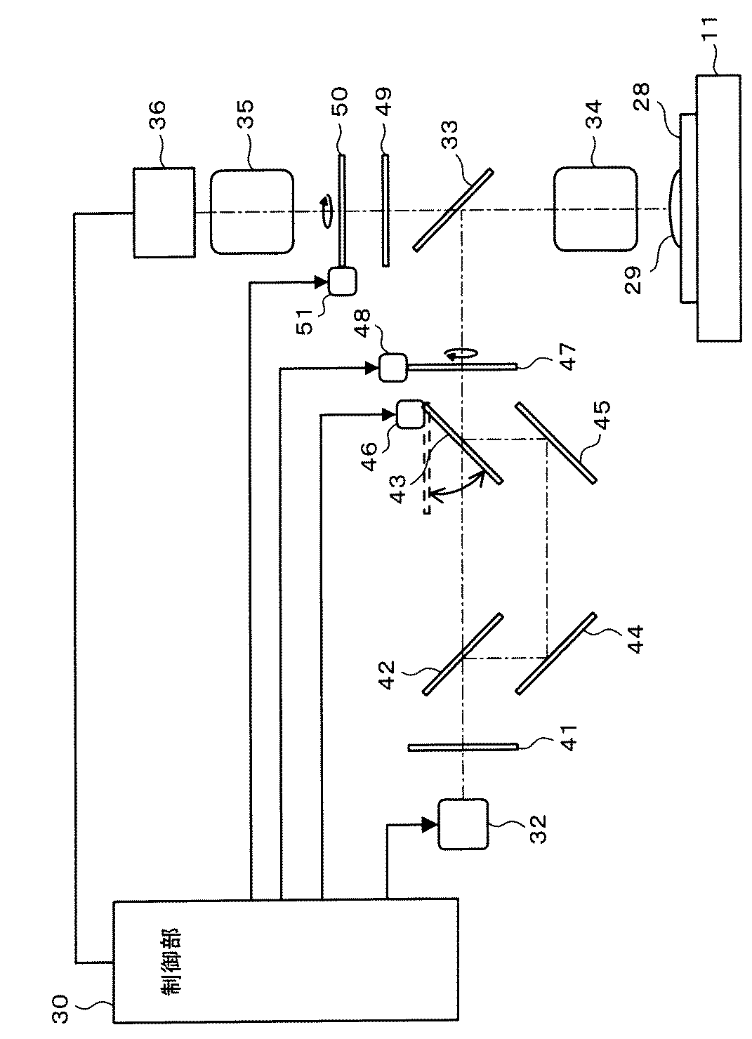
図5は、横軸に紫外線の照射を開始してからの時間(硬化時間)をとり、縦軸に偏光度ρをとって、光硬化性樹脂29から放射される蛍光の偏光度の経時変化を示す図である。この図5のように、光硬化性樹脂29の硬化にともなって偏光度ρの値は上昇するが、ある程度硬化が完了すると偏光度ρの値はほぼ一定となる。予め光硬化性樹脂29が十分に硬化したときの偏光度ρの値を調べておき、光硬化性樹脂29の硬化が完了したか否かの判定に使用するしきい値を決めておく。
In FIG. 5, the horizontal axis represents time (curing time) after the start of ultraviolet irradiation, and the vertical axis represents the degree of polarization ρ, and the temporal change in the degree of polarization of the fluorescence emitted from the
次に、ステップS23において、制御部10は、光硬化性樹脂29の硬化が完了したか否かを判定する。例えば、偏光度ρが予め設定されたしきい値に到達していない画素が一定割合以上ある場合は、光硬化性樹脂29の硬化が完了していないと判定する。そして、ステップS12に戻り、上述した処理を繰り返す。一方、制御部10は、偏光度ρが予め設定されたしきい値に到達した画素が一定割合を超えると、光硬化性樹脂29の硬化が完了したと判定して処理を終了する。
Next, in step S <b> 23, the
本実施形態によれば、硬化状態の二次元分布を容易に取得することができ、光硬化性樹脂の厚さに関係なく、樹脂の硬化状態を高精度に検出することができる。また、ステージや光学系を移動しなくてもよいので、装置の構造が比較的簡単であり、測定に要する時間が短いという利点もある。 According to this embodiment, the two-dimensional distribution of the cured state can be easily acquired, and the cured state of the resin can be detected with high accuracy regardless of the thickness of the photocurable resin. In addition, since it is not necessary to move the stage and the optical system, there is an advantage that the structure of the apparatus is relatively simple and the time required for measurement is short.
ところで、樹脂によっては一方向に偏光した光の照射だけでは硬化が十分でないことが考えられる。しかし、本実施形態では偏光子22を回転させているので、光硬化性樹脂29には種々の方向に偏光した光が照射される。このため、自然光(ランダム偏光)を照射したのと同様の条件で光硬化性樹脂29を硬化させることができる。
By the way, it is thought that hardening is not enough only by irradiation of the light polarized in one direction depending on resin. However, since the
なお、本実施形態では偏光子21及び検光子25の両方を回転制御しているが、偏光子21及び検光子25のいずれか一方のみを回転制御し、他方を固定した状態として、図3のように平行ニコル状態及び直交ニコル状態を発生させるようにしてもよい。
In this embodiment, both the
(第2の実施形態)
図6は、第2の実施形態に係る樹脂硬化状態モニタリング装置を表したブロック図である。
(Second Embodiment)
FIG. 6 is a block diagram showing a resin curing state monitoring apparatus according to the second embodiment.
本実施形態に係る樹脂硬化状態モニタリング装置は、ステージ11と、光源32と、ダイクロイックミラー33と、対物レンズ34と、結像レンズ35と、カメラ36と、制御部30とを有する。
The resin curing state monitoring apparatus according to the present embodiment includes a stage 11, a
光源32とダイクロイックミラー33との間には、フィルタ41、偏光ビームスプリッタ42、切替ミラー43、反射ミラー44,45及びλ/2板47が配置されている。また、ダイクロイックミラー33と結像レンズ35との間には、フィルタ49及び検光子(偏光板)50が配置されている。光硬化性樹脂29が付着した観察対象物28は、ステージ11上に配置される。
Between the
光源32は、制御部30から出力される信号により点灯する。本実施形態においても、光源32として水銀ランプ、レーザダイオード又はLED等を使用する。
The
フィルタ41は、光源32から出射された光に含まれる余分な波長の光をカットする。偏光ビームスプリッタ42は、フィルタ41を透過した光のうちP偏光を透過し、S偏光を反射する。偏光ビームスプリッタ42を透過したP偏光は直接切替ミラー43に到達し、偏光ビームスプリッタ42で反射されたS偏光は反射ミラー44,45で反射されて切替ミラー43に到達する。
The
切替ミラー43は、制御部30により制御される駆動装置46により駆動され、λ/2板47の回転に同期したタイミングで図6中に実線で示す位置と破線で示す位置との間を移動する。これにより、P偏光とS偏光とを交互にλ/2板47に伝達することが可能になる。
The switching
λ/2板47は、制御部30により制御される駆動装置48により一方向に一定の速度で回転する。λ/2板47を透過した光は、ダイクロイックミラー33で反射されてステージ11上の観察対象物28に向かう。そして、対物レンズ34により集光されて、観察対象物28に付着した光硬化性樹脂29を照射する。この光の照射により光硬化性樹脂29が硬化し、光硬化性樹脂29から蛍光が発生する。
The λ / 2
光硬化性樹脂29で発生した蛍光は、ダイクロイックミラー33を透過し、フィルタ49により余分な波長の光がカットされた後、検光子50に到達する。
Fluorescence generated in the
検光子50は、制御部30により制御される駆動装置51により一方向に一定の速度で回転する。検光子50は、検光子50に到達した光のうち検光子50の透過軸に平行な振動成分の光のみを透過する。
The
検光子50を透過した光は、結像レンズ35を介してカメラ36の撮像面に到達する。本実施形態においても、カメラ36として、多数の画素(受光部)が二次元方向に配列したイメージセンサを内蔵したものを使用することができる。カメラ36で撮影した光硬化性樹脂29の蛍光画像は、制御部30に送られる。
The light transmitted through the
制御部30は、第1の実施形態と同様にカメラ36から送られてきた画像から画素毎の硬化度を算出し、光硬化性樹脂29の硬化状態の二次元分布を取得する。そして、制御部30は、硬化度に基づいて光硬化性樹脂29の硬化が完了したか否かを判定する。
The
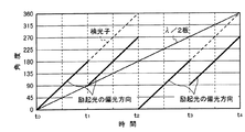
図7は、横軸に時間をとり、縦軸にλ/2板47及び検光子50の角度(基準位置からの遅相軸又は透過軸の角度)をとって、λ/2板47の遅相軸の角度、検光子50の透過軸の角度及び励起光の偏光方向の角度の経時的変化を示す図である。また、図8は、横軸に時間をとり、縦軸にλ/2板47の遅相軸及び検光子50の偏光軸とのなす角度(以下、「相対角度」という)をとって、検光子50の透過軸と励起光の偏光方向との相対角度の経時的変化を示す図である。これらの図7,図8を参照して、λ/2板47及び検光子50の動作について説明する。
In FIG. 7, the horizontal axis represents time, and the vertical axis represents the angle of the λ / 2
制御部30は、光源32を点灯するとともに、駆動装置48,50を制御してλ/2板47及び検光子50の回転を開始する。図7に示すようにλ/2板47及び検光子50は同期して回転するが、λ/2板47が1回転する間に検光子50は2回転する。また、制御部30は、λ/2板47の遅相軸の角度が0度、90度、180度及び270度になるタイミングで切替ミラー43の位置を切り替える。
The
切替ミラー43の切り替えによって、図7,図8に示すように、λ/2板47の角度が0度〜90度の間、及び180度〜270度の間は、励起光の偏光方向と検光子50の透過軸との相対角度が0度となる。この間に制御部30は光硬化性樹脂29の蛍光像をカメラ36により撮影し、平行ニコル状態の画像Ip(t,x,y)として保存する。
By switching the switching
また、λ/2板47の角度が90度〜180度の間、及び270度〜360度の間は、励起光の偏光方向と検光子50の透過軸との相対角度が90度となる。この間に制御部30は光硬化性樹脂29の蛍光像をカメラ36により撮影し、直交ニコル状態の画像Ic(t,x,y)として保存する。
Further, when the angle of the λ / 2
そして、第1の実施形態と同様に、前述の(1)式により偏光度ρを算出し、その結果に基づいて光硬化性樹脂29の硬化が完了したか否かを判定する。
Then, similarly to the first embodiment, the degree of polarization ρ is calculated by the above-described equation (1), and it is determined whether the curing of the
本実施形態においても、第1の実施形態と同様に、硬化状態の二次元分布を容易に取得することができ、光硬化性樹脂の厚さに関係なく、樹脂の硬化状態を高精度に検出することができる。また、ステージや光学系を移動しなくてもよいので、装置の構造が比較的簡単であり、測定に要する時間が短いという利点もある。 In this embodiment as well, as in the first embodiment, the two-dimensional distribution of the cured state can be easily obtained, and the cured state of the resin can be detected with high accuracy regardless of the thickness of the photocurable resin. can do. In addition, since it is not necessary to move the stage and the optical system, there is an advantage that the structure of the apparatus is relatively simple and the time required for measurement is short.
以上の諸実施形態に関し、更に以下の付記を開示する。 The following additional notes are disclosed with respect to the above embodiments.
(付記1)直線偏光した光を光硬化性樹脂に照射する直線偏光照射部と、
前記光硬化性樹脂で発生した蛍光を撮影するカメラと、
前記光硬化性樹脂と前記カメラとの間に配置された検光子と、
前記光硬化性樹脂に照射される直線偏光の偏光方向及び前記検光子の少なくとも一方を回転させる駆動装置と、
前記カメラで撮影した画像から前記光硬化性樹脂の硬化度を算出する制御部と
を有することを特徴とする樹脂硬化状態モニタリング装置。
(Appendix 1) A linearly polarized light irradiation unit that irradiates a photocurable resin with linearly polarized light;
A camera for photographing the fluorescence generated by the photocurable resin;
An analyzer disposed between the photocurable resin and the camera;
A driving device for rotating at least one of a polarization direction of linearly polarized light irradiated to the photocurable resin and the analyzer;
And a controller for calculating a degree of curing of the photocurable resin from an image photographed by the camera.
(付記2)前記カメラは、2次元方向に配列した複数の画素を有することを特徴とする付記1に記載の樹脂硬化状態モニタリング装置。
(Additional remark 2) The said camera has a some pixel arranged in the two-dimensional direction, The resin hardening state monitoring apparatus of
(付記3)前記直線偏光照射部が、
光源と、
前記光源と前記光硬化性樹脂との間に配置された偏光子と、
前記偏光子を透過した光を前記光硬化性樹脂に向けて反射するダイクロイックミラーとを有し、
前記光硬化性樹脂で発生した蛍光は前記ダイクロイックミラーを透過して前記検光子に到達することを特徴とする付記1又は2に記載の樹脂硬化状態モニタリング装置。
(Supplementary Note 3) The linearly polarized light irradiation unit is
A light source;
A polarizer disposed between the light source and the photocurable resin;
A dichroic mirror that reflects the light transmitted through the polarizer toward the photocurable resin;
The resin curing state monitoring device according to
(付記4)前記偏光子及び前記検光子が同期して回転することを特徴とする付記3に記載の樹脂硬化状態モニタリング装置。 (Supplementary note 4) The resin curing state monitoring apparatus according to supplementary note 3, wherein the polarizer and the analyzer rotate in synchronization.
(付記5)前記偏光子は一方向に一定の速度で回転し、前記検光子は正転及び逆転することを特徴とする付記4に記載の樹脂硬化状態モニタリング装置。
(Supplementary note 5) The resin cured state monitoring device according to
(付記6)前記直線偏光照射部が、
光源と、
λ/2板と、
前記光源と前記λ/2板との間に配置された偏光ビームスプリッタと、
前記偏光ビームスプリッタで分離されたP偏光とS偏光とを交互に前記λ/2板に伝達する切替ミラーと、
前記λ/2板を透過した光を前記光硬化性樹脂に向けて反射するダイクロイックミラーとを有し、
前記光硬化性樹脂で発生した蛍光は前記ダイクロイックミラーを透過して前記検光子に到達することを特徴とする付記1又は2に記載の樹脂硬化状態モニタリング装置。
(Appendix 6) The linearly polarized light irradiation unit is
A light source;
a λ / 2 plate;
A polarizing beam splitter disposed between the light source and the λ / 2 plate;
A switching mirror that alternately transmits P-polarized light and S-polarized light separated by the polarizing beam splitter to the λ / 2 plate;
A dichroic mirror that reflects the light transmitted through the λ / 2 plate toward the photocurable resin;
The resin curing state monitoring device according to
(付記7)前記λ/2板及び前記検光子が同期して回転することを特徴とする付記6に記載の樹脂硬化状態モニタリング装置。 (Supplementary note 7) The resin cured state monitoring device according to supplementary note 6, wherein the λ / 2 plate and the analyzer rotate synchronously.
(付記8)光硬化性樹脂に直線偏光した光を照射する工程と、
前記光硬化性樹脂で発生した蛍光のうち前記光硬化性樹脂に照射された光と同一方向に偏光した光と直交する方向に偏光した光とをカメラで交互に撮影する工程と、
前記カメラで撮影した画像から前記光硬化性樹脂の硬化度を算出する工程とを有し、
前記光硬化性樹脂とカメラとの間に検光子を配置し、前記検光子を回転させながら前記撮影を行うことを特徴とする樹脂硬化状態モニタリング方法。
(Appendix 8) A step of irradiating the photocurable resin with linearly polarized light;
The step of alternately photographing with the camera the light polarized in the direction orthogonal to the light polarized in the same direction as the light irradiated to the photocurable resin among the fluorescence generated in the photocurable resin,
A step of calculating the degree of curing of the photocurable resin from an image photographed by the camera,
A resin curing state monitoring method, wherein an analyzer is disposed between the photocurable resin and a camera, and the imaging is performed while rotating the analyzer.
(付記9)前記カメラは、2次元方向に配列した複数の画素を有することを特徴とする付記8に記載の樹脂硬化状態モニタリング方法。 (Additional remark 9) The said camera has a some pixel arranged in the two-dimensional direction, The resin hardening state monitoring method of Additional remark 8 characterized by the above-mentioned.
10,30…制御部、11…ステージ、12,32…光源、13,33…ダイクロイックミラー、14,34…対物レンズ、15,35…結像レンズ、16,36…カメラ、21,24,41,49…フィルタ、22…偏光子、23,26,48,51…駆動装置、25,50…検光子、28…観察対象物、29…光硬化性樹脂、42…偏光ビームスプリッタ、43…切替ミラー、44,45…反射ミラー、47…λ/2板。
DESCRIPTION OF
Claims (5)
前記光硬化性樹脂で発生した蛍光を撮影するカメラと、
前記光硬化性樹脂と前記カメラとの間に配置された検光子と、
前記光硬化性樹脂に照射される直線偏光の偏光方向及び前記検光子の少なくとも一方を回転させる駆動装置と、
前記カメラで撮影した画像から前記光硬化性樹脂の硬化度を算出する制御部と
を有することを特徴とする樹脂硬化状態モニタリング装置。 A linearly polarized light irradiation unit that irradiates the photocurable resin with linearly polarized light; and
A camera for photographing the fluorescence generated by the photocurable resin;
An analyzer disposed between the photocurable resin and the camera;
A driving device for rotating at least one of a polarization direction of linearly polarized light irradiated to the photocurable resin and the analyzer;
And a controller for calculating a degree of curing of the photocurable resin from an image photographed by the camera.
光源と、
前記光源と前記光硬化性樹脂との間に配置された偏光子と、
前記偏光子を透過した光を前記光硬化性樹脂に向けて反射するダイクロイックミラーとを有し、
前記光硬化性樹脂で発生した蛍光は前記ダイクロイックミラーを透過して前記検光子に到達することを特徴とする請求項1又は2に記載の樹脂硬化状態モニタリング装置。 The linearly polarized light irradiation unit is
A light source;
A polarizer disposed between the light source and the photocurable resin;
A dichroic mirror that reflects the light transmitted through the polarizer toward the photocurable resin;
The resin curing state monitoring apparatus according to claim 1 or 2, wherein the fluorescence generated in the photocurable resin passes through the dichroic mirror and reaches the analyzer.
光源と、
λ/2板と、
前記光源と前記λ/2板との間に配置された偏光ビームスプリッタと、
前記偏光ビームスプリッタで分離されたP偏光とS偏光とを交互に前記λ/2板に伝達する切替ミラーと、
前記λ/2板を透過した光を前記光硬化性樹脂に向けて反射するダイクロイックミラーとを有し、
前記光硬化性樹脂で発生した蛍光は前記ダイクロイックミラーを透過して前記検光子に到達することを特徴とする請求項1又は2に記載の樹脂硬化状態モニタリング装置。 The linearly polarized light irradiation unit is
A light source;
a λ / 2 plate;
A polarizing beam splitter disposed between the light source and the λ / 2 plate;
A switching mirror that alternately transmits P-polarized light and S-polarized light separated by the polarizing beam splitter to the λ / 2 plate;
A dichroic mirror that reflects the light transmitted through the λ / 2 plate toward the photocurable resin;
The resin curing state monitoring apparatus according to claim 1 or 2, wherein the fluorescence generated in the photocurable resin passes through the dichroic mirror and reaches the analyzer.
前記光硬化性樹脂で発生した蛍光のうち前記光硬化性樹脂に照射された光と同一方向に偏光した光と直交する方向に偏光した光とをカメラで交互に撮影する工程と、
前記カメラで撮影した画像から前記光硬化性樹脂の硬化度を算出する工程とを有し、
前記光硬化性樹脂とカメラとの間に検光子を配置し、前記検光子を回転させながら前記撮影を行うことを特徴とする樹脂硬化状態モニタリング方法。 Irradiating photo-curing resin with linearly polarized light;
Steps of alternately photographing light polarized in the direction orthogonal to light polarized in the same direction as the light emitted to the photocurable resin among the fluorescence generated in the photocurable resin; and
A step of calculating the degree of curing of the photocurable resin from an image photographed by the camera,
A resin curing state monitoring method, wherein an analyzer is disposed between the photocurable resin and a camera, and the imaging is performed while rotating the analyzer.
Priority Applications (1)
| Application Number | Priority Date | Filing Date | Title |
|---|---|---|---|
| JP2012031236A JP5900000B2 (en) | 2012-02-16 | 2012-02-16 | Resin cure state monitoring device and resin cure state monitoring method |
Applications Claiming Priority (1)
| Application Number | Priority Date | Filing Date | Title |
|---|---|---|---|
| JP2012031236A JP5900000B2 (en) | 2012-02-16 | 2012-02-16 | Resin cure state monitoring device and resin cure state monitoring method |
Publications (2)
| Publication Number | Publication Date |
|---|---|
| JP2013167542A true JP2013167542A (en) | 2013-08-29 |
| JP5900000B2 JP5900000B2 (en) | 2016-04-06 |
Family
ID=49178049
Family Applications (1)
| Application Number | Title | Priority Date | Filing Date |
|---|---|---|---|
| JP2012031236A Expired - Fee Related JP5900000B2 (en) | 2012-02-16 | 2012-02-16 | Resin cure state monitoring device and resin cure state monitoring method |
Country Status (1)
| Country | Link |
|---|---|
| JP (1) | JP5900000B2 (en) |
Cited By (2)
| Publication number | Priority date | Publication date | Assignee | Title |
|---|---|---|---|---|
| JP2015141038A (en) * | 2014-01-27 | 2015-08-03 | 富士通株式会社 | Cured state of resin monitoring device and cured state of resin monitoring method |
| KR101953864B1 (en) * | 2017-09-18 | 2019-05-23 | (주)바이오니아 | System for multi-channel fluorescence detection having a rotatable cylindrical filter-wheel |
Citations (7)
| Publication number | Priority date | Publication date | Assignee | Title |
|---|---|---|---|---|
| US4651011A (en) * | 1985-06-03 | 1987-03-17 | At&T Technologies, Inc. | Non-destructive method for determining the extent of cure of a polymer |
| JPH07248293A (en) * | 1990-04-30 | 1995-09-26 | Atochem North America Inc | Surface reforming detector system |
| JPH0843307A (en) * | 1994-07-28 | 1996-02-16 | Nec Corp | Inspection device and inspection method for oriented film |
| JPH1030964A (en) * | 1996-07-12 | 1998-02-03 | Mitsutoyo Corp | Wavelength measuring device for two-frequency laser light source |
| JP2003262595A (en) * | 2002-03-07 | 2003-09-19 | Hitachi Electronics Eng Co Ltd | Foreign matter inspection device |
| JP2006284243A (en) * | 2005-03-31 | 2006-10-19 | Japan Science & Technology Agency | High time resolution imaging method and apparatus, and total reflection fluorescence microscope |
| JP2007511243A (en) * | 2003-09-19 | 2007-05-10 | ザ・ジェネラル・ホスピタル・コーポレイション | Fluorescence polarization imaging apparatus and method |
-
2012
- 2012-02-16 JP JP2012031236A patent/JP5900000B2/en not_active Expired - Fee Related
Patent Citations (8)
| Publication number | Priority date | Publication date | Assignee | Title |
|---|---|---|---|---|
| US4651011A (en) * | 1985-06-03 | 1987-03-17 | At&T Technologies, Inc. | Non-destructive method for determining the extent of cure of a polymer |
| JPS62503120A (en) * | 1985-06-03 | 1987-12-10 | アメリカン テレフオン アンド テレグラフ カムパニ− | Non-destructive method for determining degree of cure of polymers |
| JPH07248293A (en) * | 1990-04-30 | 1995-09-26 | Atochem North America Inc | Surface reforming detector system |
| JPH0843307A (en) * | 1994-07-28 | 1996-02-16 | Nec Corp | Inspection device and inspection method for oriented film |
| JPH1030964A (en) * | 1996-07-12 | 1998-02-03 | Mitsutoyo Corp | Wavelength measuring device for two-frequency laser light source |
| JP2003262595A (en) * | 2002-03-07 | 2003-09-19 | Hitachi Electronics Eng Co Ltd | Foreign matter inspection device |
| JP2007511243A (en) * | 2003-09-19 | 2007-05-10 | ザ・ジェネラル・ホスピタル・コーポレイション | Fluorescence polarization imaging apparatus and method |
| JP2006284243A (en) * | 2005-03-31 | 2006-10-19 | Japan Science & Technology Agency | High time resolution imaging method and apparatus, and total reflection fluorescence microscope |
Cited By (2)
| Publication number | Priority date | Publication date | Assignee | Title |
|---|---|---|---|---|
| JP2015141038A (en) * | 2014-01-27 | 2015-08-03 | 富士通株式会社 | Cured state of resin monitoring device and cured state of resin monitoring method |
| KR101953864B1 (en) * | 2017-09-18 | 2019-05-23 | (주)바이오니아 | System for multi-channel fluorescence detection having a rotatable cylindrical filter-wheel |
Also Published As
| Publication number | Publication date |
|---|---|
| JP5900000B2 (en) | 2016-04-06 |
Similar Documents
| Publication | Publication Date | Title |
|---|---|---|
| CN101821659B (en) | Chromatic confocal sensor | |
| JP6363382B2 (en) | Film thickness measuring apparatus and method | |
| KR102235642B1 (en) | Optical system using spatial light modulator and method of measuring physical properties using the same | |
| US9176074B2 (en) | Pattern inspection method and pattern inspection apparatus | |
| WO2010058759A1 (en) | Transparent body inspecting device | |
| JP5867073B2 (en) | Resin cure state monitoring device and resin cure state monitoring method | |
| WO2016027797A1 (en) | Device for measuring material by using ghost imaging | |
| US20160313548A1 (en) | Method for capturing image of three-dimensional structure of specimen and microscopic device | |
| JP5900000B2 (en) | Resin cure state monitoring device and resin cure state monitoring method | |
| KR101423829B1 (en) | 3D Shape Mesurement Mehod and Device by using Amplitude of Projection Grating | |
| WO2007046601A1 (en) | Apparatus for and method of measuring image | |
| US7365344B2 (en) | Scanning fluorescent microscope | |
| JP6217748B2 (en) | Refractive index measuring device | |
| JP2008152065A5 (en) | ||
| WO2017138083A1 (en) | V-block refractometer | |
| CN114384020B (en) | Large-field microscopic imaging method | |
| JP6187284B2 (en) | Resin cure state monitoring device and resin cure state monitoring method | |
| KR101799775B1 (en) | Laser interferometer and measurement method using the same | |
| CN116958276A (en) | Three-dimensional object recognition method and device | |
| JP2015163844A5 (en) | ||
| JP5842670B2 (en) | Photocuring resin curing monitoring method, curing monitoring apparatus, and curing monitoring program | |
| JP4785116B2 (en) | Light wave distance meter | |
| CN112219096A (en) | Method and system for measuring optical shear of a birefringent device beyond the diffraction limit | |
| JP2011180039A (en) | Specimen damage analyzer | |
| JP2004156996A (en) | Film thickness measuring apparatus |
Legal Events
| Date | Code | Title | Description |
|---|---|---|---|
| A621 | Written request for application examination |
Free format text: JAPANESE INTERMEDIATE CODE: A621 Effective date: 20141007 |
|
| A977 | Report on retrieval |
Free format text: JAPANESE INTERMEDIATE CODE: A971007 Effective date: 20150813 |
|
| A131 | Notification of reasons for refusal |
Free format text: JAPANESE INTERMEDIATE CODE: A131 Effective date: 20150818 |
|
| A521 | Written amendment |
Free format text: JAPANESE INTERMEDIATE CODE: A523 Effective date: 20150918 |
|
| TRDD | Decision of grant or rejection written | ||
| A01 | Written decision to grant a patent or to grant a registration (utility model) |
Free format text: JAPANESE INTERMEDIATE CODE: A01 Effective date: 20160209 |
|
| A61 | First payment of annual fees (during grant procedure) |
Free format text: JAPANESE INTERMEDIATE CODE: A61 Effective date: 20160222 |
|
| R150 | Certificate of patent or registration of utility model |
Ref document number: 5900000 Country of ref document: JP Free format text: JAPANESE INTERMEDIATE CODE: R150 |
|
| LAPS | Cancellation because of no payment of annual fees |