JP2013149631A - Method of manufacturing spark plug - Google Patents
Method of manufacturing spark plug Download PDFInfo
- Publication number
- JP2013149631A JP2013149631A JP2013097954A JP2013097954A JP2013149631A JP 2013149631 A JP2013149631 A JP 2013149631A JP 2013097954 A JP2013097954 A JP 2013097954A JP 2013097954 A JP2013097954 A JP 2013097954A JP 2013149631 A JP2013149631 A JP 2013149631A
- Authority
- JP
- Japan
- Prior art keywords
- spark plug
- ground electrode
- energy beam
- high energy
- tip
- Prior art date
- Legal status (The legal status is an assumption and is not a legal conclusion. Google has not performed a legal analysis and makes no representation as to the accuracy of the status listed.)
- Granted
Links
- 238000004519 manufacturing process Methods 0.000 title claims abstract description 54
- 238000002844 melting Methods 0.000 claims abstract description 90
- 230000008018 melting Effects 0.000 claims abstract description 90
- 229910000510 noble metal Inorganic materials 0.000 claims abstract description 41
- 238000000034 method Methods 0.000 claims abstract description 37
- 229910052751 metal Inorganic materials 0.000 claims abstract description 29
- 239000002184 metal Substances 0.000 claims abstract description 29
- 239000012212 insulator Substances 0.000 claims abstract description 25
- 230000001678 irradiating effect Effects 0.000 claims abstract description 22
- 230000004927 fusion Effects 0.000 claims description 18
- 230000003247 decreasing effect Effects 0.000 claims description 6
- 238000010894 electron beam technology Methods 0.000 claims description 4
- 239000000835 fiber Substances 0.000 claims description 4
- 230000000149 penetrating effect Effects 0.000 claims description 3
- 238000003466 welding Methods 0.000 abstract description 11
- 238000010586 diagram Methods 0.000 description 20
- 238000012360 testing method Methods 0.000 description 20
- 238000001816 cooling Methods 0.000 description 14
- 230000008646 thermal stress Effects 0.000 description 12
- 239000000463 material Substances 0.000 description 9
- 230000015572 biosynthetic process Effects 0.000 description 7
- 239000011162 core material Substances 0.000 description 5
- 239000000454 talc Substances 0.000 description 5
- 229910052623 talc Inorganic materials 0.000 description 5
- PXHVJJICTQNCMI-UHFFFAOYSA-N Nickel Chemical compound [Ni] PXHVJJICTQNCMI-UHFFFAOYSA-N 0.000 description 4
- 238000002485 combustion reaction Methods 0.000 description 4
- 230000007423 decrease Effects 0.000 description 4
- 238000011156 evaluation Methods 0.000 description 4
- 230000002093 peripheral effect Effects 0.000 description 4
- KDLHZDBZIXYQEI-UHFFFAOYSA-N Palladium Chemical compound [Pd] KDLHZDBZIXYQEI-UHFFFAOYSA-N 0.000 description 3
- 238000009826 distribution Methods 0.000 description 3
- BASFCYQUMIYNBI-UHFFFAOYSA-N platinum Chemical compound [Pt] BASFCYQUMIYNBI-UHFFFAOYSA-N 0.000 description 3
- RYGMFSIKBFXOCR-UHFFFAOYSA-N Copper Chemical compound [Cu] RYGMFSIKBFXOCR-UHFFFAOYSA-N 0.000 description 2
- 229910045601 alloy Inorganic materials 0.000 description 2
- 239000000956 alloy Substances 0.000 description 2
- 239000000919 ceramic Substances 0.000 description 2
- 230000006835 compression Effects 0.000 description 2
- 238000007906 compression Methods 0.000 description 2
- 229910052802 copper Inorganic materials 0.000 description 2
- 239000010949 copper Substances 0.000 description 2
- 238000002474 experimental method Methods 0.000 description 2
- 229910001026 inconel Inorganic materials 0.000 description 2
- 238000005304 joining Methods 0.000 description 2
- 229910052759 nickel Inorganic materials 0.000 description 2
- 238000012856 packing Methods 0.000 description 2
- 239000010948 rhodium Substances 0.000 description 2
- 238000007789 sealing Methods 0.000 description 2
- 229910000575 Ir alloy Inorganic materials 0.000 description 1
- 229910001209 Low-carbon steel Inorganic materials 0.000 description 1
- 229910000990 Ni alloy Inorganic materials 0.000 description 1
- KJTLSVCANCCWHF-UHFFFAOYSA-N Ruthenium Chemical compound [Ru] KJTLSVCANCCWHF-UHFFFAOYSA-N 0.000 description 1
- PNEYBMLMFCGWSK-UHFFFAOYSA-N aluminium oxide Inorganic materials [O-2].[O-2].[O-2].[Al+3].[Al+3] PNEYBMLMFCGWSK-UHFFFAOYSA-N 0.000 description 1
- 238000005452 bending Methods 0.000 description 1
- 230000007797 corrosion Effects 0.000 description 1
- 238000005260 corrosion Methods 0.000 description 1
- 238000002788 crimping Methods 0.000 description 1
- 238000001125 extrusion Methods 0.000 description 1
- 238000010304 firing Methods 0.000 description 1
- 229910052741 iridium Inorganic materials 0.000 description 1
- GKOZUEZYRPOHIO-UHFFFAOYSA-N iridium atom Chemical compound [Ir] GKOZUEZYRPOHIO-UHFFFAOYSA-N 0.000 description 1
- 239000000203 mixture Substances 0.000 description 1
- 229910052763 palladium Inorganic materials 0.000 description 1
- 229910052697 platinum Inorganic materials 0.000 description 1
- 239000000843 powder Substances 0.000 description 1
- 229910052702 rhenium Inorganic materials 0.000 description 1
- WUAPFZMCVAUBPE-UHFFFAOYSA-N rhenium atom Chemical compound [Re] WUAPFZMCVAUBPE-UHFFFAOYSA-N 0.000 description 1
- 229910052703 rhodium Inorganic materials 0.000 description 1
- MHOVAHRLVXNVSD-UHFFFAOYSA-N rhodium atom Chemical compound [Rh] MHOVAHRLVXNVSD-UHFFFAOYSA-N 0.000 description 1
- 230000000630 rising effect Effects 0.000 description 1
- 229910052707 ruthenium Inorganic materials 0.000 description 1
- 238000004088 simulation Methods 0.000 description 1
Images


Classifications
-
- H—ELECTRICITY
- H01—ELECTRIC ELEMENTS
- H01T—SPARK GAPS; OVERVOLTAGE ARRESTERS USING SPARK GAPS; SPARKING PLUGS; CORONA DEVICES; GENERATING IONS TO BE INTRODUCED INTO NON-ENCLOSED GASES
- H01T21/00—Apparatus or processes specially adapted for the manufacture or maintenance of spark gaps or sparking plugs
- H01T21/02—Apparatus or processes specially adapted for the manufacture or maintenance of spark gaps or sparking plugs of sparking plugs
-
- H—ELECTRICITY
- H01—ELECTRIC ELEMENTS
- H01T—SPARK GAPS; OVERVOLTAGE ARRESTERS USING SPARK GAPS; SPARKING PLUGS; CORONA DEVICES; GENERATING IONS TO BE INTRODUCED INTO NON-ENCLOSED GASES
- H01T13/00—Sparking plugs
- H01T13/20—Sparking plugs characterised by features of the electrodes or insulation
- H01T13/38—Selection of materials for insulation
Landscapes
- Engineering & Computer Science (AREA)
- Manufacturing & Machinery (AREA)
- Spark Plugs (AREA)
Abstract
【課題】接地電極と貴金属チップとの溶接強度を向上させることのできる技術を提供することを目的とする。
【解決手段】絶縁体と、中心電極と、主体金具と、接地電極と、接地電極に設けられ、中心電極との間で火花放電間隙を形成する放電面を有する貴金属チップと、を備えるスパークプラグの製造方法は、接地電極と貴金属チップとの境界に対して高エネルギービームを照射することによって溶融部を形成する溶融部形成工程を備える。溶融部形成工程では、溶融部を放電面に垂直な方向に投影した場合に、接地電極と貴金属チップとが重なり合っている部分の面積のうちの80%以上の面積が、投影された溶融部と重なり合うように、かつ、放電面に垂直な方向から見た場合における溶融部の形状が、接地電極の幅方向に垂直であって貴金属チップの中心を通過する中心線に対して、略対称となるように、溶融部を形成する。
【選択図】図3An object of the present invention is to provide a technique capable of improving the welding strength between a ground electrode and a noble metal tip.
A spark plug comprising an insulator, a center electrode, a metal shell, a ground electrode, and a noble metal tip provided on the ground electrode and having a discharge surface that forms a spark discharge gap with the center electrode. The manufacturing method includes a melting part forming step of forming a melting part by irradiating a boundary between the ground electrode and the noble metal tip with a high energy beam. In the melted portion forming step, when the melted portion is projected in a direction perpendicular to the discharge surface, 80% or more of the area of the portion where the ground electrode and the noble metal tip overlap is projected with the projected melted portion. The shape of the melted part as viewed from the direction perpendicular to the discharge surface is substantially symmetric with respect to the center line perpendicular to the width direction of the ground electrode and passing through the center of the noble metal tip. As such, the melted part is formed.
[Selection] Figure 3
Description
本発明は、スパークプラグの製造方法に関するものである。 The present invention relates to a method for manufacturing a spark plug.
従来、スパークプラグの接地電極に貴金属チップを接合する方法としては、例えば、以下の特許文献に開示されたものが知られている。 Conventionally, as a method for joining a noble metal tip to a ground electrode of a spark plug, for example, those disclosed in the following patent documents are known.
特許文献1に開示された方法では、貴金属チップを全て溶融させて、接地電極に接合させている。しかしこの方法では、接地電極と貴金属チップとの溶接強度を上げることはできるが、貴金属チップの放電面にも接地電極母材の溶融成分が含まれてしまうため、火花耐久性能が低下してしまうといった問題があった。
In the method disclosed in
また、特許文献2に開示された方法では、貴金属チップの外周部を溶融させて、接地電極に接合させている。しかしこの方法では、接地電極と貴金属チップの中心部との溶接強度が弱く、また貴金属チップや溶融部にクラックが発生し、やがては貴金属チップの剥離に繋がるおそれがあるといった問題があった。
In the method disclosed in
また、接地電極に貴金属チップを接合する方法としては、抵抗溶接を用いた方法も知られている。しかしこの方法では、接地電極と貴金属チップの境界面における溶融部の層が薄いため、また、近年のエンジンの高出力化に伴ってスパークプラグの使用環境もより高温で厳しい環境となるため、溶接強度が確保できず、やがては貴金属チップの剥離に繋がるおそれがあるといった問題があった。 A method using resistance welding is also known as a method for joining a noble metal tip to a ground electrode. However, with this method, the layer of the fusion zone at the interface between the ground electrode and the noble metal tip is thin, and the use environment of the spark plug becomes more severe at higher temperatures as the engine output increases in recent years. There was a problem that the strength could not be ensured and eventually the noble metal tip could be peeled off.
本発明は、上述した従来の課題を解決するためになされたものであり、接地電極と貴金属チップとの溶接強度を向上させることのできる技術を提供することを目的とする。 The present invention has been made to solve the above-described conventional problems, and an object thereof is to provide a technique capable of improving the welding strength between a ground electrode and a noble metal tip.
本発明は、上述の課題の少なくとも一部を解決するために、以下の形態または適用例を取ることが可能である。 In order to solve at least a part of the problems described above, the present invention can take the following forms or application examples.
[適用例1]
軸線方向に貫通する軸孔を有する絶縁体と、
前記軸孔の先端側に設けられた中心電極と、
前記絶縁体を保持する略筒状の主体金具と、
一端部が前記主体金具の先端部に取り付けられ、他端が前記中心電極の先端部と対向する接地電極と、
前記接地電極の前記中心電極の先端部と対向する面に設けられ、前記中心電極との間で火花放電間隙を形成する放電面を有する貴金属チップと、
を備えるスパークプラグの製造方法であって、
前記接地電極と前記貴金属チップとの境界に対して高エネルギービームを照射することによって溶融部を形成する溶融部形成工程を備え、
前記溶融部形成工程では、
前記溶融部を前記放電面に垂直な方向に投影した場合に、前記接地電極と前記貴金属チップとが重なり合っている部分の面積のうちの80%以上の面積が、前記投影された溶融部と重なり合うように、
かつ、
前記放電面に垂直な方向から見た場合における前記溶融部の形状が、前記接地電極の幅方向に垂直であって前記貴金属チップの中心を通過する中心線に対して、略対称となるように、前記溶融部を形成する、スパークプラグの製造方法。
適用例1のスパークプラグの製造方法によれば、接地電極と貴金属チップとの境界に占める溶融部の面積が大きくなるため、接地電極と貴金属チップとの溶接強度を向上させたスパークプラグを製造することができる。さらに、溶融部の形状が中心線に対して略対称となるため、中心線を中心とした左右の熱応力の差をほぼゼロにすることができる。したがって、熱応力差による溶接強度の低下を抑制することができる。
[Application Example 1]
An insulator having an axial hole penetrating in the axial direction;
A center electrode provided on the tip side of the shaft hole;
A substantially cylindrical metal shell for holding the insulator;
One end is attached to the tip of the metal shell, and the other end is a ground electrode facing the tip of the center electrode,
A noble metal tip having a discharge surface provided on a surface of the ground electrode facing the tip of the center electrode and forming a spark discharge gap with the center electrode;
A spark plug manufacturing method comprising:
A melting part forming step of forming a melting part by irradiating a high energy beam to a boundary between the ground electrode and the noble metal tip;
In the melting part forming step,
When the molten part is projected in a direction perpendicular to the discharge surface, an area of 80% or more of the area where the ground electrode and the noble metal tip overlap overlaps the projected molten part. like,
And,
The shape of the molten part when viewed from a direction perpendicular to the discharge surface is substantially symmetric with respect to a center line that is perpendicular to the width direction of the ground electrode and passes through the center of the noble metal tip. A method for producing a spark plug, wherein the melting part is formed.
According to the spark plug manufacturing method of Application Example 1, since the area of the melted portion that occupies the boundary between the ground electrode and the noble metal tip is increased, a spark plug with improved welding strength between the ground electrode and the noble metal tip is manufactured. be able to. Further, since the shape of the melted portion is substantially symmetric with respect to the center line, the difference between the left and right thermal stresses around the center line can be made substantially zero. Therefore, it is possible to suppress a decrease in welding strength due to a thermal stress difference.
[適用例2]
適用例1に記載のスパークプラグの製造方法であって、
前記溶融部形成工程は、
前記高エネルギービームを前記境界に対して相対的に往復移動させながら照射し、前記境界の一部に対しては前記高エネルギービームを二度以上照射することによって、前記溶融部の形状を前記中心線に対して略対称とする工程を含むことを特徴とする、スパークプラグの製造方法。
適用例2のスパークプラグの製造方法によれば、貴金属チップの中心線に対して略対称な形状を有する溶融部を形成することができる。
[Application Example 2]
A spark plug manufacturing method according to Application Example 1,
The melting part forming step includes
Irradiating the high energy beam while reciprocally moving relative to the boundary, and irradiating a part of the boundary with the high energy beam twice or more, thereby changing the shape of the molten part to the center. A method for manufacturing a spark plug, comprising a step of making the line substantially symmetrical with respect to a line.
According to the spark plug manufacturing method of Application Example 2, it is possible to form a melted portion having a substantially symmetric shape with respect to the center line of the noble metal tip.
[適用例3]
適用例1または適用例2に記載のスパークプラグの製造方法であって、
前記溶融部形成工程は、
前記高エネルギービームを前記境界に対して相対的に移動させながら照射し、前記高エネルギービームの出力を前記相対移動に伴って変化させることによって、前記溶融部の形状を前記中心線に対して略対称とする工程を含むことを特徴とする、スパークプラグの製造方法。
適用例3のスパークプラグの製造方法によれば、貴金属チップの中心線に対して略対称な形状を有する溶融部を形成することができる。
[Application Example 3]
A method for manufacturing a spark plug according to Application Example 1 or Application Example 2,
The melting part forming step includes
By irradiating the high energy beam while moving it relative to the boundary, and changing the output of the high energy beam along with the relative movement, the shape of the melting part is substantially reduced with respect to the center line. A method for producing a spark plug, comprising a step of making it symmetrical.
According to the spark plug manufacturing method of the application example 3, it is possible to form the melted portion having a shape that is substantially symmetrical with respect to the center line of the noble metal tip.
[適用例4]
適用例3に記載のスパークプラグの製造方法であって、
前記溶融部形成工程は、
前記高エネルギービームを前記境界に対して相対的に移動させながら照射し、前記高エネルギービームの出力を前記相対移動の開始後は一定とし、その後次第に前記高エネルギービームの出力を小さくすることによって、前記溶融部の形状を前記中心線に対して略対称とする工程を含むことを特徴とする、スパークプラグの製造方法。
適用例5のスパークプラグの製造方法によれば、略直方体形状のような貴金属チップの中心線に対して略対称な形状を有する溶融部を形成することができる。
[Application Example 4]
A spark plug manufacturing method according to Application Example 3,
The melting part forming step includes
Irradiating while moving the high energy beam relative to the boundary, and making the output of the high energy beam constant after the start of the relative movement, and then gradually decreasing the output of the high energy beam, A method for manufacturing a spark plug, comprising a step of making the shape of the melted portion substantially symmetric with respect to the center line.
According to the spark plug manufacturing method of Application Example 5, it is possible to form a melted portion having a substantially symmetric shape with respect to the center line of the noble metal tip, such as a substantially rectangular parallelepiped shape.
[適用例5]
適用例3に記載のスパークプラグの製造方法であって、
前記溶融部形成工程は、
前記高エネルギービームを前記境界に対して相対的に移動させながら照射し、前記高エネルギービームの出力を前記中心線の手前までは大きくしていき、その後、前記高エネルギービームの出力を徐々に小さくすることによって、前記溶融部の形状を前記中心線に対して略対称とする工程を含むことを特徴とする、スパークプラグの製造方法。
適用例5のスパークプラグの製造方法によれば、略円柱形状のような貴金属チップの中心線に対して略対称な形状を有する溶融部を形成することができる。
[Application Example 5]
A spark plug manufacturing method according to Application Example 3,
The melting part forming step includes
The high energy beam is irradiated while being moved relative to the boundary, and the output of the high energy beam is increased up to the center line, and then the output of the high energy beam is gradually decreased. By doing this, the process of making the shape of the said fusion | melting part substantially symmetrical with respect to the said centerline is included, The manufacturing method of the spark plug characterized by the above-mentioned.
According to the spark plug manufacturing method of Application Example 5, it is possible to form a melted portion having a substantially symmetric shape with respect to the center line of the noble metal tip such as a substantially cylindrical shape.
[適用例6]
適用例1ないし適用例5のいずれか一項に記載のスパークプラグの製造方法であって、
前記溶融部形成工程は、
前記高エネルギービームは、前記境界に対して照射される前から照射されていることを特徴とする、スパークプラグの製造方法。
適用例6のスパークプラグの製造方法によれば、出力が安定した状態の高エネルギービームを境界に対して照射することができるので、溶融部の形状を形成する際の精度を向上させることができる。
[Application Example 6]
A spark plug manufacturing method according to any one of Application Examples 1 to 5,
The melting part forming step includes
The method of manufacturing a spark plug, wherein the high energy beam is irradiated before being irradiated to the boundary.
According to the spark plug manufacturing method of the application example 6, since the boundary can be irradiated with a high energy beam having a stable output, the accuracy in forming the shape of the melted portion can be improved. .
[適用例7]
適用例1ないし適用例6のいずれか一項に記載のスパークプラグの製造方法であって、
前記溶融部形成工程は、
前記境界で規定される面に対して平行な方向から前記高エネルギービームを照射する工程を含むことを特徴とする、スパークプラグの製造方法。
適用例7のスパークプラグの製造方法によれば、接地電極と貴金属チップの境界を適切に溶融させることができる。
[Application Example 7]
A method for manufacturing a spark plug according to any one of Application Examples 1 to 6,
The melting part forming step includes
A method of manufacturing a spark plug, comprising a step of irradiating the high energy beam from a direction parallel to a plane defined by the boundary.
According to the spark plug manufacturing method of Application Example 7, the boundary between the ground electrode and the noble metal tip can be appropriately melted.
[適用例8]
適用例1ないし適用例7のいずれか一項に記載のスパークプラグの製造方法であって、
前記溶融部形成工程は、
前記境界で規定される面に対して斜めの方向から前記高エネルギービームを照射する工程を含むことを特徴とする、スパークプラグの製造方法。
適用例8のスパークプラグの製造方法によれば、接地電極と貴金属チップの境界を適切に溶融させることができる。
[Application Example 8]
A spark plug manufacturing method according to any one of Application Examples 1 to 7,
The melting part forming step includes
A method for manufacturing a spark plug, comprising a step of irradiating the high energy beam from a direction oblique to a plane defined by the boundary.
According to the spark plug manufacturing method of the application example 8, the boundary between the ground electrode and the noble metal tip can be appropriately melted.
[適用例9]
適用例1ないし適用例8のいずれか一項に記載のスパークプラグの製造方法であって、
前記高エネルギービームは、ファイバーレーザまたは電子ビームであることを特徴とする、スパークプラグの製造方法。
適用例9のスパークプラグの製造方法によれば、接地電極と貴金属チップの境界を奥深くまで適切に溶融させることができる。
[Application Example 9]
A method for manufacturing a spark plug according to any one of Application Examples 1 to 8,
The method of manufacturing a spark plug, wherein the high energy beam is a fiber laser or an electron beam.
According to the manufacturing method of the spark plug of Application Example 9, the boundary between the ground electrode and the noble metal tip can be appropriately melted deeply.
なお、本発明は、種々の態様で実現することが可能である。例えば、スパークプラグの製造方法および製造装置、製造システム等の形態で実現することができる。 Note that the present invention can be realized in various modes. For example, it can be realized in the form of a spark plug manufacturing method, manufacturing apparatus, manufacturing system, and the like.
次に、本発明の一態様であるスパークプラグの実施の形態を、以下の順序で説明する。
A.第1実施形態:
B.酸化スケールの発生に関する実験例:
C.溶融部重なり率に関する実験例:
D.その他の実施形態:
E.溶融部が中心線に対して略対称か否かについての判定基準:
Next, an embodiment of a spark plug that is one embodiment of the present invention will be described in the following order.
A. First embodiment:
B. Experimental example for the generation of oxide scale:
C. Example of experiment on melt overlap rate:
D. Other embodiments:
E. Criteria for determining whether the melted part is substantially symmetric about the center line:
A.第1実施形態:
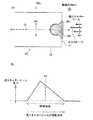
図1は、本発明の一実施形態としてのスパークプラグ100の部分断面図である。なお、図1において、スパークプラグ100の軸線方向ODを図面における上下方向とし、下側をスパークプラグ100の先端側、上側を後端側として説明する。
A. First embodiment:
FIG. 1 is a partial cross-sectional view of a
スパークプラグ100は、絶縁碍子10と、主体金具50と、中心電極20と、接地電極30と、端子金具40とを備えている。中心電極20は、絶縁碍子10内に軸線方向ODに延びた状態で保持されている。絶縁碍子10は、絶縁体として機能しており、主体金具50は、この絶縁碍子10を保持している。端子金具40は、絶縁碍子10の後端部に設けられている。なお、中心電極20と接地電極30の構成については、図2において詳述する。
The
絶縁碍子10は、アルミナ等を焼成して形成され、軸中心に軸線方向ODへ延びる軸孔12が形成された筒形状を有する。軸線方向ODの略中央には外径が最も大きな鍔部19が形成されており、それより後端側(図1における上側)には後端側胴部18が形成されている。鍔部19より先端側(図1における下側)には、後端側胴部18よりも外径の小さな先端側胴部17が形成され、さらにその先端側胴部17よりも先端側に、先端側胴部17よりも外径の小さな脚長部13が形成されている。脚長部13は先端側ほど縮径され、スパークプラグ100が内燃機関のエンジンヘッド200に取り付けられた際には、その燃焼室に曝される。脚長部13と先端側胴部17との間には段部15が形成されている。
The
主体金具50は、低炭素鋼材より形成された円筒状の金具であり、スパークプラグ100を内燃機関のエンジンヘッド200に固定する。そして、主体金具50は、絶縁碍子10を内部に保持しており、絶縁碍子10は、その後端側胴部18の一部から脚長部13にかけての部位を主体金具50によって取り囲まれている。
The
また、主体金具50は、工具係合部51と、取付ねじ部52とを備えている。工具係合部51は、スパークプラグレンチ(図示せず)が嵌合する部位である。主体金具50の取付ねじ部52は、ねじ山が形成された部位であり、内燃機関の上部に設けられたエンジンヘッド200の取付ねじ孔201に螺合する。
The
主体金具50の工具係合部51と取付ねじ部52との間には、鍔状のシール部54が形成されている。取付ねじ部52とシール部54との間のねじ首59には、板体を折り曲げて形成した環状のガスケット5が嵌挿されている。ガスケット5は、スパークプラグ100をエンジンヘッド200に取り付けた際に、シール部54の座面55と取付ねじ孔201の開口周縁部205との間で押し潰されて変形する。このガスケット5の変形により、スパークプラグ100とエンジンヘッド200間が封止され、取付ねじ孔201を介したエンジン内の気密漏れが防止される。
Between the tool engaging portion 51 and the mounting
主体金具50の工具係合部51より後端側には、薄肉の加締部53が設けられている。また、シール部54と工具係合部51との間には、加締部53と同様に、薄肉の座屈部58が設けられている。主体金具50の工具係合部51から加締部53にかけての内周面と、絶縁碍子10の後端側胴部18の外周面との間には、円環状のリング部材6,7が介在されている。さらに両リング部材6,7間にタルク(滑石)9の粉末が充填されている。加締部53を内側に折り曲げるようにして加締めると、絶縁碍子10は、リング部材6,7およびタルク9を介して主体金具50内の先端側に向け押圧される。これにより、絶縁碍子10の段部15は、主体金具50の内周に形成された段部56に支持され、主体金具50と絶縁碍子10とは、一体となる。このとき、主体金具50と絶縁碍子10との間の気密性は、絶縁碍子10の段部15と主体金具50の段部56との間に介在された環状の板パッキン8によって保持され、燃焼ガスの流出が防止される。座屈部58は、加締めの際に、圧縮力の付加に伴い外向きに撓み変形するように構成されており、タルク9の圧縮ストロークを稼いで主体金具50内の気密性を高めている。なお、主体金具50の段部56よりも先端側と絶縁碍子10との間には、所定寸法のクリアランスCLRが設けられている。
A
図2は、スパークプラグ100の中心電極20の先端部22付近の拡大図である。中心電極20は、電極母材21の内部に芯材25を埋設した構造を有する棒状の電極である。電極母材21は、インコネル(商標名)600または601等のニッケルまたはニッケルを主成分とする合金から形成されている。芯材25は、電極母材21よりも熱伝導性に優れる銅または銅を主成分とする合金から形成されている。通常、中心電極20は、有底筒状に形成された電極母材21の内部に芯材25を詰め、底側から押出成形を行って引き延ばすことで作製される。芯材25は、胴部分においては略一定の外径をなすものの、先端側においては縮径部が形成される。また、中心電極20は、軸孔12内を後端側に向けて延設され、シール体4およびセラミック抵抗3(図1)を経由して、端子金具40(図1)に電気的に接続されている。端子金具40には、高圧ケーブル(図示せず)がプラグキャップ(図示せず)を介して接続され、高電圧が印加される。
FIG. 2 is an enlarged view of the vicinity of the
中心電極20の先端部22は、絶縁碍子10の先端部11よりも突出している。中心電極20の先端部22の先端には、中心電極チップ90が接合されている。中心電極チップ90は、軸線方向ODに伸びた略円柱形状を有しており、耐火花消耗性を向上するため、高融点の貴金属によって形成されている。中心電極チップ90は、例えば、イリジウム(Ir)や、Irを主成分として、白金(Pt)、ロジウム(Rh)、ルテニウム(Ru)、パラジウム(Pd)、レニウム(Re)のうち、1種類あるいは2種類以上を添加したIr合金によって形成される。
The
接地電極30は、耐腐食性の高い金属から形成され、例えば、インコネル(商標名)600または601等のニッケル合金から形成されている。この接地電極30の基部32は、溶接によって、主体金具50の先端部57に接合されている。また、接地電極30は屈曲しており、接地電極30の先端部33は、中心電極チップ90の先端面92と対向している。
The
さらに、接地電極30の先端部33には、溶融部98を介して接地電極チップ95が接合されている。接地電極チップ95の放電面96は、中心電極チップ90の先端面92と対向しており、接地電極チップ95の放電面96と、中心電極チップ90の先端面92との間には、ギャップGが形成されている。なお、接地電極チップ95は、中心電極チップ90と同様の材料で形成することができる。
Further, a
図3(A)は、接地電極30の先端部33を、軸線方向ODに沿った方向から見た図である。図3(B)は、図3(A)におけるB−B断面を示す図である。図3(B)に示すように、接地電極チップ95は、接地電極30に形成された溝部分に埋設されている。接地電極チップ95と接地電極30との間の少なくとも一部には、溶融部98が形成されている。溶融部98は、接地電極チップ95の一部と接地電極30の一部とが溶け合って形成されており、接地電極チップ95と接地電極30の成分の両方が含まれる。すなわち、溶融部98は、接地電極30と接地電極チップ95との中間的な組成を有している。なお、実際には軸線方向ODに沿った方向からは溶融部98の大部分は見えないが、説明上、図3(A)においても溶融部98を描いている。以下で示す図面においても同様である。また、接地電極チップ95と接地電極30との間には破線が描かれているが、実際には、溶融部98が形成されている部分においては接地電極チップ95と接地電極30とが一体となって溶融しており、破線は消滅している。以下で示す図面においても同様である。
FIG. 3A is a view of the
溶融部98は、接地電極30と接地電極チップ95との境界に対して略平行な方向LDから高エネルギービームを照射することによって形成することができる。溶融部98を形成するための高エネルギービームとしては、例えば、ファイバーレーザや電子ビームを用いることが好ましい。ファイバーレーザや電子ビームを用いると、接地電極30と接地電極チップ95の境界を奥深くまで溶融させることができるため、接地電極30と接地電極チップ95とを強固に接合させることができる。
The
ここで、図3(A)に示すように、接地電極30と接地電極チップ95とが重なり合っている部分(クロスハッチングが施された領域X)の面積をSとする。そして、溶融部98を接地電極チップ95の放電面96に垂直な方向(すなわち軸線方向OD)に投影した場合に、面積Sのうちの80%以上が、投影された溶融部98と重なり合っていることが好ましい。このようにすれば、溶融部98近傍における酸化スケールの発生を抑制することができる。この根拠については、後述する。なお、この図3(A)においては、面積Sのうちの100%が、溶融部98と重なり合っている。また、以下では、面積Sにおける溶融部98と重なり合っている部分の割合を、「溶融部重なり率LR(%)」とも呼ぶ。
Here, as shown in FIG. 3A, the area of the portion where the
さらに、図3(A)に示すように、接地電極30の幅方向WDに垂直であって接地電極チップ95の中心を通過する線を、中心線CLとする。この場合において、接地電極チップ95の放電面96に垂直な方向(軸線方向OD)から見た場合における溶融部98の形状は、中心線CLに対して、略対称であることが好ましい。このようにすれば、接地電極30及び接地電極チップ95に発生する熱応力の分布を、中心線CLに対して対称とすることができ、中心線CLを中心とした左右の熱応力差をほぼゼロにすることができる。したがって、左右の熱応力の差によって溶接強度が低下することを抑制することができる。
Further, as shown in FIG. 3A, a line that is perpendicular to the width direction WD of the
図4は、溶融部98の形成過程の一例を示す説明図である。図3(A)で示した略対称形状の溶融部98を形成するには、まず、高エネルギービームを接地電極30と接地電極チップ95との境界に対して相対的に移動させながら照射する(図4(A))。そうすると、図4(A)に示すように、溶融部98のうち、最初に高エネルギービームが照射された部分Fは、溶融深さが足りず、溶融部98は、図3(A)に示すような略対称な形状とはならない。この理由は、溶融部98のうち最初に高エネルギービームが照射された部分は、高エネルギービームによってまだ十分に加熱されておらず、十分な溶融深さが得られるほど温度が高くなっていないためであると考えられる。そこで、図4(B)に示すように、溶融部98のうちの溶融深さが足りない部分に対しては、高エネルギービームを往復移動させ、高エネルギービームを2度照射させる。こうすれば、溶融部98のうちの溶融深さが足りなかった部分の溶融深さが補われ、溶融部98の形状を略対称形状とすることができる。なお、高エネルギービームを2度照射しても溶融部98が略対称な形状とならない場合には、3度以上高エネルギービームを照射することとしてもよい。また、図4(A)では、高エネルギービームを移動させているが、接地電極30と接地電極チップ95の境界を、高エネルギービームに対して移動させることとしてもよい。以下に示す図5(A)においても同様である。
FIG. 4 is an explanatory diagram showing an example of the formation process of the melted
なお、高エネルギービームは、接地電極30と接地電極チップ95との境界に対して照射される前から放出されていることとしてもよい。こうすれば、高エネルギービームの出力が安定した状態となってから、溶融部の形成を開始することができるため、溶融部の形状を形成する際の精度を向上させることができる。
The high energy beam may be emitted before being irradiated to the boundary between the
図5(A)は、溶融部98の形成過程の他の一例を示す説明図である。図5(B)は、溶融部98の形成過程における高エネルギービームの出力の変化の一例を示す説明図である。前述したように、溶融部98のうち、高エネルギービームが最初に照射される部分は、まだ十分に加熱されていないため、溶融深さが足りないことがある。したがって、溶融部98を中心線CLに対して略対称な形状とするためには、高エネルギービームの出力を相対移動に伴って変化させる。具体的には、例えば図5(B)に示すように、照射開始後は高エネルギービームを出力大の一定値として、被照射部分を十分に加熱し、その後徐々に高エネルギービームの出力を小さくすればよい。高エネルギービームの出力を徐々に小さくしても溶融部98を中心線CLに対して略対称な形状とすることができる理由は、高エネルギービームによって与えられた熱は、溶融部98を徐々に伝導し、まだ高エネルギービームが照射されていない部分の温度も高くなるためである。したがって、高エネルギービームの出力を相対移動に伴って変化させれば、溶融部98を中心線CLに対して略対称な形状とすることができる。なお、溶融部98を中心線CLに対して略対称な形状とするための高エネルギービームの出力波形としては、図5(B)に示した出力波形に限られず、接地電極30及び接地電極チップ95の材質や形状に応じて、高エネルギービームの出力を調整することが好ましい。
FIG. 5A is an explanatory diagram showing another example of the process of forming the melted
B.酸化スケールの発生に関する実験例:
溶融部の形状と、酸化スケール割合との関係を調べるために、3種類の冷熱試験1,2,3を行なった。ここで、酸化スケール割合とは、溶融部98の断面形状(図3(B))における輪郭線の長さに対する酸化スケールの長さの割合である。
B. Experimental example for the generation of oxide scale:
In order to investigate the relationship between the shape of the melted portion and the ratio of oxide scale, three types of
図6(A)は、冷熱試験に用いたサンプル1のスパークプラグの先端付近を示す図である。図6(B)は、冷熱試験に用いたサンプル2のスパークプラグの先端付近を示す図である。サンプル1のスパークプラグでは、溶融部98xが中心線CLに対して非対称な形状となっている。一方、サンプル2のスパークプラグでは、図3に示した第1実施形態と同様に、溶融部98が中心線CLに対して略対称な形状となっている。溶融部98が中心線CLに対して略対称な形状となっているか否かについての判定基準については、後述する。
FIG. 6A is a view showing the vicinity of the tip of the spark plug of
冷熱試験1では、まず接地電極30をバーナーで2分間熱し、接地電極30の温度を1000℃まで上昇させた。その後バーナーを切り、接地電極30を1分間徐冷し、再び接地電極30をバーナーで2分間熱して接地電極30の温度を1000℃まで上昇させた。このサイクルを1000回繰り返し、溶融部付近に発生した酸化スケールの長さを判断面から計測した。そして、計測された酸化スケールの長さから、酸化スケール割合を求めた。冷熱試験2の試験条件は、接地電極30の温度を1100℃まで上昇させる点以外は、冷熱試験1と同じである。同様に、冷熱試験3の試験条件は、接地電極30の温度を1200℃まで上昇させる点以外は、冷熱試験1と同じである。
In the
図6(C)は、冷熱試験の結果を示す表である。この図6(C)では、酸化スケール割合が30%未満の場合を○と評価し、30%以上50%未満の場合を△と評価し、50%以上の場合を・と評価した。図6(C)によれば、溶融部98xが中心線CLに対して非対称な形状である場合(サンプル1)には、冷熱試験1における評価は○となったが、冷熱試験2では評価は△となり、冷熱試験3では評価は・となった。この理由について説明する。溶融部98xの形状が中心線CLに対して非対称であるため、溶融部98x付近に発生する熱応力の分布は、中心線CLに対して非対称となる。その結果、中心線CLを挟んだ左右の熱応力の差が大きくなり、接地電極30と接地電極チップ95との接合強度が低下し、溶融部98x付近において酸化スケールが発生しやすくなっていると考えられる。
FIG. 6C is a table showing the results of the cooling test. In FIG. 6C, the case where the oxide scale ratio was less than 30% was evaluated as ◯, the case where it was 30% or more and less than 50% was evaluated as Δ, and the case where it was 50% or more was evaluated as. According to FIG. 6C, when the melted
一方、溶融部98が中心線CLに対して略対称な形状である場合(サンプル2)には、冷熱試験1ないし3のいずれにおいても評価は○となった。この理由について説明する。溶融部98の形状は中心線CLに対して略対称であるため、溶融部98付近に発生する熱応力の分布は、中心線CLに対して略対称となる。その結果、中心線CLを挟んだ左右の熱応力の差は、ほぼゼロとなるため、接地電極30と接地電極チップ95との接合強度を十分に確保することができる。このため、溶融部98付近において酸化スケールが発生しにくくなっていると考えられる。したがって、溶融部の形状は、中心線CLに対して略対称となっていることが好ましいことが理解できる。
On the other hand, in the case where the melted
C.溶融部重なり率に関する実験例:
上述した溶融部重なり率LRと、酸化スケール割合との関係を調べるために、溶融部重なり率の異なる複数のサンプルを用いて、上述した冷熱試験2を行なった。
C. Example of experiment on melt overlap rate:
In order to investigate the relationship between the above-described melted portion overlap rate LR and the oxide scale ratio, the above-described
図7は、冷熱試験の結果を示す図である。この図7によれば、溶融部重なり率LRが大きくなるほど、酸化スケール割合が小さくなることが理解できる。さらに、溶融部重なり率LRが80%以上の場合には、酸化スケール割合が50%未満となることが理解できる。この理由は、溶融部重なり率LRが大きいほど、接地電極30と接地電極チップ95との接合強度を高めることができ、溶融部98付近に酸化スケールが発生しにくくなるためであると考えられる。したがって、上記実施形態のように、溶融部重なり率LRは80%以上であることが好ましい。
FIG. 7 is a diagram showing the results of a cooling test. According to FIG. 7, it can be understood that the oxide scale ratio decreases as the fusion zone overlap ratio LR increases. Furthermore, it can be understood that when the melted portion overlap ratio LR is 80% or more, the oxide scale ratio is less than 50%. The reason for this is considered to be that as the melted portion overlap ratio LR increases, the bonding strength between the
D.その他の実施形態:
図8は、その他の実施形態におけるスパークプラグ100bの先端付近を拡大して示す説明図である。図8(A)は、接地電極30を、軸線方向ODに沿った方向から見た図である。図8(B)は、図8(A)におけるB−B断面を示す図である。本実施形態が、第1実施形態(図3)と異なる点は、接地電極チップ95bの形状が略円柱形となっている点と、接地電極チップ95bが接地電極30の先端面31から突出している点であり、その他の構成は第1実施形態と同じである。このように、接地電極チップは、任意の形状とすることができる。
D. Other embodiments:
FIG. 8 is an explanatory view showing, in an enlarged manner, the vicinity of the tip of the spark plug 100b in another embodiment. FIG. 8A is a view of the
図9は、その他の実施形態におけるスパークプラグ100cの先端付近を拡大して示す説明図である。図9(A)は、接地電極30を、軸線方向ODに沿った方向から見た図である。図9(B)は、図9(A)におけるB−B断面を示す図である。本実施形態が、第1実施形態(図3)と異なる点は、接地電極チップ95cの形状が略円柱形となっている点であり、その他の構成は第1実施形態と同じである。このように、接地電極チップは、任意の形状とすることができる。
FIG. 9 is an explanatory view showing, in an enlarged manner, the vicinity of the tip of the
図10は、図9に示したスパークプラグ100cにおける溶融部98cの形成過程の一例を示す説明図である。図10(B)は、溶融部98cの形成過程における高エネルギービームの出力の変化の一例を示す説明図である。このスパークプラグ100cでは、接地電極チップ95cが略円柱形となっている。したがって、溶融部98cの形状を、中心線CLに対して略対称であり、かつ、接地電極チップ95cの外周の円弧に沿った形状とするためには、高エネルギービームの出力を相対移動に伴って変化させることが好ましい。具体的には、例えば図10(A)の矢印、及び、図10(B)に示すように、高エネルギービームの出力を中心線CLの手前までは大きくしていき、その後、徐々に小さくすればよい。すなわち、高エネルギービームの出力を相対移動に伴って上げていき、中心線CLの手前でピーク値とし、その後、立ち上がり時よりも緩やかに出力を下げていけばよい。高エネルギービームの出力を中心線CLの手前でピーク値としても、溶融部98cを中心線CLに対して略対称な形状とすることができる理由は、高エネルギービームによって与えられた熱は、溶融部98cを徐々に伝導し、まだ高エネルギービームが照射されていない部分の温度も高くなるためである。したがって、高エネルギービームの出力を、図10(B)に示すような波形で、相対移動に伴って変化させれば、溶融部98cを中心線CLに対して略対称な形状であり、かつ、接地電極チップ95cの円弧に沿った形状とすることができる。
FIG. 10 is an explanatory diagram showing an example of a process of forming the melted
図11は、その他の実施形態におけるスパークプラグ100dの先端付近を拡大して示す説明図である。図11(A)は、接地電極30を、軸線方向ODに沿った方向から見た図である。図11(B)は、図11(A)におけるB−B断面を示す図である。本実施形態が、第1実施形態(図3)と異なる点は、接地電極チップ95dの方が接地電極30の先端面31からの突出量が多くなっている点と、溶融部98dを形成する場合に、接地電極30と接地電極チップ95dとの境界に対して斜めの方向LD2から高エネルギービームを照射している点である。その他の構成は第1実施形態と同じである。このように、接地電極チップは、任意の形状とすることができる。また、高エネルギービームは、接地電極30と接地電極チップ95dとの境界に対して斜めの方向から照射することとしてもよい。
FIG. 11 is an explanatory view showing, in an enlarged manner, the vicinity of the tip of the
図12は、その他の実施形態におけるスパークプラグ100eの先端付近を拡大して示す説明図である。図12(A)は、接地電極30を、軸線方向ODに垂直な方向から見た図である。図12(B)は、図12(A)におけるB−B断面を示す図である。本実施形態が、第1実施形態(図3)と異なる点は、接地電極チップ95eが接地電極30の先端面31に接合されている点と、接地電極チップ95eの放電面96eが中心電極チップ90の側面91と対向している点である。すなわち、このスパークプラグ100eは、いわゆる横放電型のスパークプラグである。
FIG. 12 is an explanatory view showing, in an enlarged manner, the vicinity of the tip of the
本実施形態では、接地電極チップ95eと接地電極30との境界に平行な方向LD3から高エネルギービームを照射することによって、溶融部98eを形成している。溶融部98eは、接地電極30の幅方向WDに垂直であって、接地電極チップ95eの中心を通過する中心線CLに対して、略対称な形状となっている。このようにすれば、横放電型のスパークプラグにおいても、中心線CLを挟んだ左右の熱応力の差をほぼゼロにすることができるので、接地電極30と接地電極チップ95eとの接合強度が低下することを抑制することができる。
In the present embodiment, the
図13は、その他の実施形態におけるスパークプラグ100fの先端付近を拡大して示す説明図である。図13(A)は、接地電極30を、軸線方向ODに垂直な方向から見た図である。図13(B)は、図13(A)におけるB−B断面を示す図である。本実施形態が、図12に示した実施形態と異なる点は、接地電極チップ95fの形状が略円柱状となっている点である。その他の構成は、図12に示した実施形態と同じである。このように、接地電極チップの形状は、任意の形状とすることができる。
FIG. 13 is an explanatory view showing, in an enlarged manner, the vicinity of the tip of the spark plug 100f according to another embodiment. FIG. 13A is a diagram of the
図14は、その他の実施形態におけるスパークプラグ100gの先端付近を拡大して示す説明図である。図14(A)は、接地電極30を、軸線方向ODに沿った方向から見た図である。図14(B)は、図14(A)におけるB−B断面を示す図である。本実施形態が、図9に示した実施形態と異なる点は、軸線方向ODに沿った方向LD4からも高エネルギービームを照射することによって、溶融部99gを形成している点である。その他の構成は、図9に示した実施形態と同じである。このように、溶融部98gに加えてさらに溶融部99gを形成すれば、接地電極30と接地電極チップ95との接合強度をさらに高めることができる。
FIG. 14 is an explanatory view showing, in an enlarged manner, the vicinity of the tip of the spark plug 100g according to another embodiment. FIG. 14A is a view of the
図15は、その他の実施形態におけるスパークプラグ100hの先端付近を拡大して示す説明図である。図15(A)は、接地電極30を、軸線方向ODに沿った方向から見た図である。図15(B)は、図15(A)におけるB−B断面を示す図である。本実施形態が、図11に示した実施形態と異なる点は、軸線方向ODに沿った方向LD4からも高エネルギービームを照射することによって、溶融部99hを形成している点である。その他の構成は、図9に示した実施形態と同じである。このように、溶融部98hに加えてさらに溶融部99hを形成すれば、接地電極30と接地電極チップ95との接合強度をさらに高めることができる。
FIG. 15 is an explanatory view showing, in an enlarged manner, the vicinity of the tip of the spark plug 100h in another embodiment. FIG. 15A is a view of the
E.溶融部が中心線に対して略対称か否かについての判定基準:
図16は、溶融部が中心線CLに対して略対称か否かについての判定基準を示す説明図である。この図16は、軸線方向ODに垂直な平面で溶融部を切断した状態を示している。本明細書では、溶融部が中心線CLに対して略対称か否かについては、溶融部の切断面における外縁を示す外縁線に着目して判定する。
E. Criteria for determining whether the melted part is substantially symmetric about the center line:
FIG. 16 is an explanatory diagram showing a criterion for determining whether or not the melted portion is substantially symmetric with respect to the center line CL. FIG. 16 shows a state in which the melted part is cut along a plane perpendicular to the axial direction OD. In this specification, whether or not the melted part is substantially symmetric with respect to the center line CL is determined by paying attention to an outer edge line indicating an outer edge of the cut surface of the melted part.
具体的には、図16(A)において、溶融部98xの外縁線のうち、中心線CLよりも下側にある外縁線を外縁線ML1とし、中心線CLよりも上側にある外縁線を外縁線ML2とする。外縁線ML1よりも許容幅SLだけ外側を沿った線を外側線AL1とし、外縁線ML1よりも許容幅SLだけ内側を沿った線を内側線BL1とする。そして、外側線AL1を中心線CLの上側に対称に投影した線を外側線AL2とし、内側線BL1を中心線CLの上側に対称に投影した線を内側線BL2とする。なお、この図16に示した例では、許容幅SLを0.2mmとした。
Specifically, in FIG. 16A, of the outer edge lines of the melted
このとき、溶融部98xの外縁線ML2の一部でも、外側線AL2及び内側線BL2とで囲まれた領域からはみ出している場合には、溶融部98は中心線CLに対して略対称ではないと判定する。一方、溶融部98xの外縁線ML2の全てが、外側線AL2及び内側線BL2とで囲まれた領域に含まれている場合には、溶融部98xは中心線CLに対して略対称であると判定する。
At this time, even if a part of the outer edge line ML2 of the
以上の判定基準を用いると、図16(A)に例示された溶融部98xの外縁線ML2は、内側線BL2よりも内側を通る部分があるため、溶融部98xは中心線CLに対して略対称ではないと判定する。一方、図16(B)に例示された溶融部98の外縁線ML2は、外側線AL2及び内側線BL2とで囲まれた領域に全て含まれているため、溶融部98は中心線CLに対して略対称であると判定する。
When the above criterion is used, since the outer edge line ML2 of the melted
なお、図16に示した例では、許容幅SLを0.2mmとして溶融部が中心線CLに対して略対称か否かを判定したが、許容幅SLの長さは、電極チップの大きさや形状に応じて適宜設定することができる。例えば、許容幅SLの長さを、電極チップの長辺の20%の長さに設定してもよい。 In the example shown in FIG. 16, it is determined whether the allowable width SL is 0.2 mm and the melted portion is substantially symmetric with respect to the center line CL. However, the length of the allowable width SL is the size of the electrode tip, It can set suitably according to a shape. For example, the length of the allowable width SL may be set to 20% of the long side of the electrode tip.
また、図16に示した例では、中心線CLの下側の外縁線ML1を基準線としていたが、この代わりに、中心線CLの上側の外縁線ML2を基準線として、溶融部が中心線CLに対して略対称か否かを判定してもよい。また、基準線は、溶融部の理想的な形状に基づいて定めるものとしてもよい。理想的な形状は、溶融部が十分に高温となって溶融した場合に得られる形状であり、図16(A)に示した例では、中心線CLより下側の外縁線ML1の方が、上側の外縁線ML2よりもこの条件に合致している。基準線は、もとよりシミュレーション等により理想的に求めてもよい。 In the example shown in FIG. 16, the outer edge line ML1 on the lower side of the center line CL is used as the reference line. Instead, the outer edge line ML2 on the upper side of the center line CL is used as the reference line, and the melted portion is center line. You may determine whether it is substantially symmetrical with respect to CL. The reference line may be determined based on the ideal shape of the melting part. The ideal shape is a shape obtained when the melted portion is melted at a sufficiently high temperature. In the example shown in FIG. 16A, the outer edge line ML1 below the center line CL is This condition is satisfied more than the upper outer edge line ML2. The reference line may be ideally obtained by simulation or the like.
3…セラミック抵抗
4…シール体
5…ガスケット
6…リング部材
8…板パッキン
9…タルク
10…絶縁碍子
11…先端部
12…軸孔
13…脚長部
15…段部
17…先端側胴部
18…後端側胴部
19…鍔部
20…中心電極
21…電極母材
22…先端部
25…芯材
30…接地電極
31…先端面
32…基部
33…先端部
40…端子金具
50…主体金具
51…工具係合部
52…取付ねじ部
53…加締部
54…シール部
55…座面
56…段部
57…先端部
58…座屈部
59…ねじ首
90…中心電極チップ
91…側面
92…先端面
95…接地電極チップ
95b…接地電極チップ
95c…接地電極チップ
95d…接地電極チップ
95e…接地電極チップ
95f…接地電極チップ
95g…接地電極チップ
95h…接地電極チップ
96…放電面
96b…放電面
96c…放電面
96d…放電面
96e…放電面
96f…放電面
96g…放電面
96h…放電面
98…溶融部
98b…溶融部
98c…溶融部
98d…溶融部
98e…溶融部
98f…溶融部
98g…溶融部
98h…溶融部
98x…溶融部
99g…溶融部
99h…溶融部
100…スパークプラグ
100b…スパークプラグ
100c…スパークプラグ
100d…スパークプラグ
100e…スパークプラグ
100f…スパークプラグ
100g…スパークプラグ
100h…スパークプラグ
200…エンジンヘッド
201…孔
205…開口周縁部
DESCRIPTION OF
軸線方向に貫通する軸孔を有する絶縁体と、
前記軸孔の先端側に設けられた中心電極と、
前記絶縁体を保持する略筒状の主体金具と、
一端部が前記主体金具の先端部に取り付けられ、他端が前記中心電極の先端部と対向する接地電極と、
前記接地電極の前記中心電極の先端部と対向する面に設けられ、前記中心電極との間で火花放電間隙を形成する放電面を有する貴金属チップと、
を備えるスパークプラグの製造方法であって、
前記接地電極と前記貴金属チップとの境界に対して高エネルギービームを照射することによって溶融部を形成する溶融部形成工程を備え、
前記溶融部形成工程では、
前記溶融部を前記放電面に垂直な方向に投影した場合に、前記接地電極と前記貴金属チップとが重なり合っている部分の面積のうちの80%以上の面積が、前記投影された溶融部と重なり合うように、
かつ、
前記放電面に垂直な方向から見た場合における前記溶融部の形状が、前記接地電極の幅方向に垂直であって前記貴金属チップの中心を通過する中心線に対して、略対称となるように、前記溶融部を形成するとともに、
前記溶融部形成工程は、
前記高エネルギービームを前記接地電極の幅方向に略垂直な方向から照射しつつ、前記高エネルギービームを前記境界に対して前記幅方向に相対的に移動させながら連続的に照射し、前記高エネルギービームの出力を前記相対移動に伴って変化させることによって、前記溶融部の形状を前記中心線に対して略対称とする工程を含むことを特徴とする、スパークプラグの製造方法。
適用例1のスパークプラグの製造方法によれば、接地電極と貴金属チップとの境界に占める溶融部の面積が大きくなるため、接地電極と貴金属チップとの溶接強度を向上させたスパークプラグを製造することができる。さらに、溶融部の形状が中心線に対して略対称となるため、中心線を中心とした左右の熱応力の差をほぼゼロにすることができる。したがって、熱応力差による溶接強度の低下を抑制することができる。
An insulator having an axial hole penetrating in the axial direction;
A center electrode provided on the tip side of the shaft hole;
A substantially cylindrical metal shell for holding the insulator;
One end is attached to the tip of the metal shell, and the other end is a ground electrode facing the tip of the center electrode,
A noble metal tip having a discharge surface provided on a surface of the ground electrode facing the tip of the center electrode and forming a spark discharge gap with the center electrode;
A spark plug manufacturing method comprising:
A melting part forming step of forming a melting part by irradiating a high energy beam to a boundary between the ground electrode and the noble metal tip;
In the melting part forming step,
When the molten part is projected in a direction perpendicular to the discharge surface, an area of 80% or more of the area where the ground electrode and the noble metal tip overlap overlaps the projected molten part. like,
And,
The shape of the molten part when viewed from a direction perpendicular to the discharge surface is substantially symmetric with respect to a center line that is perpendicular to the width direction of the ground electrode and passes through the center of the noble metal tip. And forming the melted part ,
The melting part forming step includes
While irradiating the high energy beam from a direction substantially perpendicular to the width direction of the ground electrode, the high energy beam is continuously irradiated while being moved relative to the boundary in the width direction. A method for manufacturing a spark plug , comprising a step of making a shape of the melted portion substantially symmetric with respect to the center line by changing a beam output with the relative movement .
According to the spark plug manufacturing method of Application Example 1, since the area of the melted portion that occupies the boundary between the ground electrode and the noble metal tip is increased, a spark plug with improved welding strength between the ground electrode and the noble metal tip is manufactured. be able to. Further, since the shape of the melted portion is substantially symmetric with respect to the center line, the difference between the left and right thermal stresses around the center line can be made substantially zero. Therefore, it is possible to suppress a decrease in welding strength due to a thermal stress difference.
Claims (9)
前記軸孔の先端側に設けられた中心電極と、
前記絶縁体を保持する略筒状の主体金具と、
一端部が前記主体金具の先端部に取り付けられ、他端が前記中心電極の先端部と対向する接地電極と、
前記接地電極の前記中心電極の先端部と対向する面に設けられ、前記中心電極との間で火花放電間隙を形成する放電面を有する貴金属チップと、
を備えるスパークプラグの製造方法であって、
前記接地電極と前記貴金属チップとの境界に対して高エネルギービームを照射することによって溶融部を形成する溶融部形成工程を備え、
前記溶融部形成工程では、
前記溶融部を前記放電面に垂直な方向に投影した場合に、前記接地電極と前記貴金属チップとが重なり合っている部分の面積のうちの80%以上の面積が、前記投影された溶融部と重なり合うように、
かつ、
前記放電面に垂直な方向から見た場合における前記溶融部の形状が、前記接地電極の幅方向に垂直であって前記貴金属チップの中心を通過する中心線に対して、略対称となるように、前記溶融部を形成する、スパークプラグの製造方法。 An insulator having an axial hole penetrating in the axial direction;
A center electrode provided on the tip side of the shaft hole;
A substantially cylindrical metal shell for holding the insulator;
One end is attached to the tip of the metal shell, and the other end is a ground electrode facing the tip of the center electrode,
A noble metal tip having a discharge surface provided on a surface of the ground electrode facing the tip of the center electrode and forming a spark discharge gap with the center electrode;
A spark plug manufacturing method comprising:
A melting part forming step of forming a melting part by irradiating a high energy beam to a boundary between the ground electrode and the noble metal tip;
In the melting part forming step,
When the molten part is projected in a direction perpendicular to the discharge surface, an area of 80% or more of the area where the ground electrode and the noble metal tip overlap overlaps the projected molten part. like,
And,
The shape of the molten part when viewed from a direction perpendicular to the discharge surface is substantially symmetric with respect to a center line that is perpendicular to the width direction of the ground electrode and passes through the center of the noble metal tip. A method for producing a spark plug, wherein the melting part is formed.
前記溶融部形成工程は、
前記高エネルギービームを前記境界に対して相対的に往復移動させながら照射し、前記境界の一部に対しては前記高エネルギービームを二度以上照射することによって、前記溶融部の形状を前記中心線に対して略対称とする工程を含むことを特徴とする、スパークプラグの製造方法。 It is a manufacturing method of the spark plug according to claim 1,
The melting part forming step includes
Irradiating the high energy beam while reciprocally moving relative to the boundary, and irradiating a part of the boundary with the high energy beam twice or more, thereby changing the shape of the molten part to the center. A method for manufacturing a spark plug, comprising a step of making the line substantially symmetrical with respect to a line.
前記溶融部形成工程は、
前記高エネルギービームを前記境界に対して相対的に移動させながら照射し、前記高エネルギービームの出力を前記相対移動に伴って変化させることによって、前記溶融部の形状を前記中心線に対して略対称とする工程を含むことを特徴とする、スパークプラグの製造方法。 A method of manufacturing a spark plug according to claim 1 or claim 2,
The melting part forming step includes
By irradiating the high energy beam while moving it relative to the boundary, and changing the output of the high energy beam along with the relative movement, the shape of the melting part is substantially reduced with respect to the center line. A method for producing a spark plug, comprising a step of making it symmetrical.
前記溶融部形成工程は、
前記高エネルギービームを前記境界に対して相対的に移動させながら照射し、前記高エネルギービームの出力を前記相対移動の開始後は一定とし、その後次第に前記高エネルギービームの出力を小さくすることによって、前記溶融部の形状を前記中心線に対して略対称とする工程を含むことを特徴とする、スパークプラグの製造方法。 It is a manufacturing method of the spark plug according to claim 3,
The melting part forming step includes
Irradiating while moving the high energy beam relative to the boundary, and making the output of the high energy beam constant after the start of the relative movement, and then gradually decreasing the output of the high energy beam, A method for manufacturing a spark plug, comprising a step of making the shape of the melted portion substantially symmetric with respect to the center line.
前記溶融部形成工程は、
前記高エネルギービームを前記境界に対して相対的に移動させながら照射し、前記高エネルギービームの出力を前記中心線の手前までは大きくしていき、その後、前記高エネルギービームの出力を徐々に小さくすることによって、前記溶融部の形状を前記中心線に対して略対称とする工程を含むことを特徴とする、スパークプラグの製造方法。 It is a manufacturing method of the spark plug according to claim 3,
The melting part forming step includes
The high energy beam is irradiated while being moved relative to the boundary, and the output of the high energy beam is increased up to the center line, and then the output of the high energy beam is gradually decreased. By doing this, the process of making the shape of the said fusion | melting part substantially symmetrical with respect to the said centerline is included, The manufacturing method of the spark plug characterized by the above-mentioned.
前記溶融部形成工程は、
前記高エネルギービームは、前記境界に対して照射される前から照射されていることを特徴とする、スパークプラグの製造方法。 A method for manufacturing a spark plug according to any one of claims 1 to 5,
The melting part forming step includes
The method of manufacturing a spark plug, wherein the high energy beam is irradiated before being irradiated to the boundary.
前記溶融部形成工程は、
前記境界で規定される面に対して平行な方向から前記高エネルギービームを照射する工程を含むことを特徴とする、スパークプラグの製造方法。 A method for manufacturing a spark plug according to any one of claims 1 to 6,
The melting part forming step includes
A method of manufacturing a spark plug, comprising a step of irradiating the high energy beam from a direction parallel to a plane defined by the boundary.
前記溶融部形成工程は、
前記境界で規定される面に対して斜めの方向から前記高エネルギービームを照射する工程を含むことを特徴とする、スパークプラグの製造方法。 A method for manufacturing a spark plug according to any one of claims 1 to 7,
The melting part forming step includes
A method for manufacturing a spark plug, comprising a step of irradiating the high energy beam from a direction oblique to a plane defined by the boundary.
前記高エネルギービームは、ファイバーレーザまたは電子ビームであることを特徴とする、スパークプラグの製造方法。
A method for manufacturing a spark plug according to any one of claims 1 to 8,
The method of manufacturing a spark plug, wherein the high energy beam is a fiber laser or an electron beam.
Priority Applications (1)
| Application Number | Priority Date | Filing Date | Title |
|---|---|---|---|
| JP2013097954A JP5475906B2 (en) | 2009-03-31 | 2013-05-07 | Manufacturing method of spark plug |
Applications Claiming Priority (3)
| Application Number | Priority Date | Filing Date | Title |
|---|---|---|---|
| JP2009084691 | 2009-03-31 | ||
| JP2009084691 | 2009-03-31 | ||
| JP2013097954A JP5475906B2 (en) | 2009-03-31 | 2013-05-07 | Manufacturing method of spark plug |
Related Parent Applications (1)
| Application Number | Title | Priority Date | Filing Date |
|---|---|---|---|
| JP2010533772A Division JP5319692B2 (en) | 2009-03-31 | 2010-03-17 | Manufacturing method of spark plug |
Publications (2)
| Publication Number | Publication Date |
|---|---|
| JP2013149631A true JP2013149631A (en) | 2013-08-01 |
| JP5475906B2 JP5475906B2 (en) | 2014-04-16 |
Family
ID=42827722
Family Applications (2)
| Application Number | Title | Priority Date | Filing Date |
|---|---|---|---|
| JP2010533772A Active JP5319692B2 (en) | 2009-03-31 | 2010-03-17 | Manufacturing method of spark plug |
| JP2013097954A Active JP5475906B2 (en) | 2009-03-31 | 2013-05-07 | Manufacturing method of spark plug |
Family Applications Before (1)
| Application Number | Title | Priority Date | Filing Date |
|---|---|---|---|
| JP2010533772A Active JP5319692B2 (en) | 2009-03-31 | 2010-03-17 | Manufacturing method of spark plug |
Country Status (6)
| Country | Link |
|---|---|
| US (1) | US8506341B2 (en) |
| EP (1) | EP2416461B1 (en) |
| JP (2) | JP5319692B2 (en) |
| KR (1) | KR101550089B1 (en) |
| CN (1) | CN102379072B (en) |
| WO (1) | WO2010113404A1 (en) |
Cited By (2)
| Publication number | Priority date | Publication date | Assignee | Title |
|---|---|---|---|---|
| JP2017164811A (en) * | 2016-03-09 | 2017-09-21 | 日本特殊陶業株式会社 | Laser welding method, welded joint manufacturing method, spark plug electrode manufacturing method, and spark plug manufacturing method |
| JP2020119798A (en) * | 2019-01-25 | 2020-08-06 | 日本特殊陶業株式会社 | Spark plug |
Families Citing this family (7)
| Publication number | Priority date | Publication date | Assignee | Title |
|---|---|---|---|---|
| CN103155314B (en) | 2010-09-29 | 2014-10-08 | 日本特殊陶业株式会社 | Spark plug |
| JP5642032B2 (en) * | 2011-08-17 | 2014-12-17 | 日本特殊陶業株式会社 | Spark plug |
| US8715025B2 (en) | 2012-02-23 | 2014-05-06 | Fram Group Ip Llc | Laser welded spark plug electrode and method of forming the same |
| JP6293107B2 (en) * | 2015-12-03 | 2018-03-14 | 日本特殊陶業株式会社 | Spark plug |
| US10201876B2 (en) * | 2016-03-09 | 2019-02-12 | Ngk Spark Plug Co., Ltd. | Laser welding method, method for manufacturing welded body, method for manufacturing electrode for spark plug, and method for manufacturing spark plug |
| JP6347818B2 (en) * | 2016-03-16 | 2018-06-27 | 日本特殊陶業株式会社 | Spark plug |
| JP6793154B2 (en) * | 2018-06-13 | 2020-12-02 | 日本特殊陶業株式会社 | Spark plug |
Citations (10)
| Publication number | Priority date | Publication date | Assignee | Title |
|---|---|---|---|---|
| JPH0645050A (en) * | 1992-07-27 | 1994-02-18 | Ngk Spark Plug Co Ltd | Manufacture of spark plug |
| JPH08298178A (en) * | 1995-04-27 | 1996-11-12 | Ngk Spark Plug Co Ltd | Spark plug and manufacture thereof |
| JPH09106880A (en) * | 1995-10-11 | 1997-04-22 | Denso Corp | Spark plug for internal combustion engine |
| JPH10112374A (en) * | 1996-10-07 | 1998-04-28 | Denso Corp | Spark plug and its manufacture |
| JP2002093547A (en) * | 2000-07-10 | 2002-03-29 | Denso Corp | Spark plug |
| JP2002231417A (en) * | 2001-01-31 | 2002-08-16 | Ngk Spark Plug Co Ltd | Method of manufacturing spark plug |
| JP2002237365A (en) * | 2001-02-08 | 2002-08-23 | Denso Corp | Spark plug and manufacturing method of the same |
| JP2004517459A (en) * | 2001-01-24 | 2004-06-10 | ローベルト ボツシユ ゲゼルシヤフト ミツト ベシユレンクテル ハフツング | Method for the production of spark plug electrodes |
| JP2007118078A (en) * | 2005-09-30 | 2007-05-17 | Nissan Motor Co Ltd | Laser welding method and laser welding system |
| JP2008270185A (en) * | 2007-03-29 | 2008-11-06 | Ngk Spark Plug Co Ltd | Spark plug manufacturing method |
Family Cites Families (10)
| Publication number | Priority date | Publication date | Assignee | Title |
|---|---|---|---|---|
| JPH0557466A (en) * | 1991-09-03 | 1993-03-09 | Toyota Motor Corp | Laser beam welding equipment |
| JPH0737674A (en) | 1993-07-26 | 1995-02-07 | Ngk Spark Plug Co Ltd | Spark plug |
| JP3121309B2 (en) * | 1998-02-16 | 2000-12-25 | 株式会社デンソー | Spark plugs for internal combustion engines |
| US6997767B2 (en) * | 2003-03-28 | 2006-02-14 | Ngk Spark Plug Co., Ltd. | Method for manufacturing a spark plug, and spark plug |
| US7557495B2 (en) | 2005-11-08 | 2009-07-07 | Paul Tinwell | Spark plug having precious metal pad attached to ground electrode and method of making same |
| JP2007265843A (en) * | 2006-03-29 | 2007-10-11 | Ngk Spark Plug Co Ltd | Method of manufacturing spark plug for internal combustion engine |
| JP2008123343A (en) * | 2006-11-14 | 2008-05-29 | Sharp Corp | Software differential measurement device, software differential measurement program, and recording medium recording it |
| JP4402731B2 (en) * | 2007-08-01 | 2010-01-20 | 日本特殊陶業株式会社 | Spark plug for internal combustion engine and method of manufacturing spark plug |
| JP5047363B2 (en) * | 2008-10-10 | 2012-10-10 | 日本特殊陶業株式会社 | Spark plug and manufacturing method thereof |
| JP5173036B2 (en) * | 2010-04-16 | 2013-03-27 | 日本特殊陶業株式会社 | Spark plug for internal combustion engine and method of manufacturing spark plug |
-
2010
- 2010-03-17 KR KR1020117025720A patent/KR101550089B1/en active IP Right Grant
- 2010-03-17 CN CN201080014807.0A patent/CN102379072B/en active Active
- 2010-03-17 WO PCT/JP2010/001916 patent/WO2010113404A1/en active Application Filing
- 2010-03-17 EP EP10758189.4A patent/EP2416461B1/en active Active
- 2010-03-17 JP JP2010533772A patent/JP5319692B2/en active Active
- 2010-03-17 US US13/138,720 patent/US8506341B2/en active Active
-
2013
- 2013-05-07 JP JP2013097954A patent/JP5475906B2/en active Active
Patent Citations (10)
| Publication number | Priority date | Publication date | Assignee | Title |
|---|---|---|---|---|
| JPH0645050A (en) * | 1992-07-27 | 1994-02-18 | Ngk Spark Plug Co Ltd | Manufacture of spark plug |
| JPH08298178A (en) * | 1995-04-27 | 1996-11-12 | Ngk Spark Plug Co Ltd | Spark plug and manufacture thereof |
| JPH09106880A (en) * | 1995-10-11 | 1997-04-22 | Denso Corp | Spark plug for internal combustion engine |
| JPH10112374A (en) * | 1996-10-07 | 1998-04-28 | Denso Corp | Spark plug and its manufacture |
| JP2002093547A (en) * | 2000-07-10 | 2002-03-29 | Denso Corp | Spark plug |
| JP2004517459A (en) * | 2001-01-24 | 2004-06-10 | ローベルト ボツシユ ゲゼルシヤフト ミツト ベシユレンクテル ハフツング | Method for the production of spark plug electrodes |
| JP2002231417A (en) * | 2001-01-31 | 2002-08-16 | Ngk Spark Plug Co Ltd | Method of manufacturing spark plug |
| JP2002237365A (en) * | 2001-02-08 | 2002-08-23 | Denso Corp | Spark plug and manufacturing method of the same |
| JP2007118078A (en) * | 2005-09-30 | 2007-05-17 | Nissan Motor Co Ltd | Laser welding method and laser welding system |
| JP2008270185A (en) * | 2007-03-29 | 2008-11-06 | Ngk Spark Plug Co Ltd | Spark plug manufacturing method |
Cited By (2)
| Publication number | Priority date | Publication date | Assignee | Title |
|---|---|---|---|---|
| JP2017164811A (en) * | 2016-03-09 | 2017-09-21 | 日本特殊陶業株式会社 | Laser welding method, welded joint manufacturing method, spark plug electrode manufacturing method, and spark plug manufacturing method |
| JP2020119798A (en) * | 2019-01-25 | 2020-08-06 | 日本特殊陶業株式会社 | Spark plug |
Also Published As
| Publication number | Publication date |
|---|---|
| EP2416461A4 (en) | 2013-11-20 |
| JP5319692B2 (en) | 2013-10-16 |
| JP5475906B2 (en) | 2014-04-16 |
| JPWO2010113404A1 (en) | 2012-10-04 |
| KR101550089B1 (en) | 2015-09-03 |
| CN102379072A (en) | 2012-03-14 |
| CN102379072B (en) | 2014-04-30 |
| WO2010113404A1 (en) | 2010-10-07 |
| EP2416461A1 (en) | 2012-02-08 |
| KR20120003923A (en) | 2012-01-11 |
| US20120015578A1 (en) | 2012-01-19 |
| EP2416461B1 (en) | 2019-05-08 |
| US8506341B2 (en) | 2013-08-13 |
Similar Documents
| Publication | Publication Date | Title |
|---|---|---|
| JP5475906B2 (en) | Manufacturing method of spark plug | |
| JP5192611B2 (en) | Spark plug | |
| JP4619443B2 (en) | Spark plug | |
| JP5905056B2 (en) | Spark plug and method of manufacturing spark plug | |
| JP5576753B2 (en) | Manufacturing method of spark plug | |
| JP6328088B2 (en) | Spark plug | |
| JP5296677B2 (en) | Spark plug | |
| JP5213782B2 (en) | Spark plug | |
| JP6347818B2 (en) | Spark plug | |
| JP5421212B2 (en) | Spark plug | |
| JP6293107B2 (en) | Spark plug | |
| JP2013118082A (en) | Spark plug and spark plug manufacturing method |
Legal Events
| Date | Code | Title | Description |
|---|---|---|---|
| A521 | Request for written amendment filed |
Free format text: JAPANESE INTERMEDIATE CODE: A523 Effective date: 20130531 |
|
| A621 | Written request for application examination |
Free format text: JAPANESE INTERMEDIATE CODE: A621 Effective date: 20130605 |
|
| A977 | Report on retrieval |
Free format text: JAPANESE INTERMEDIATE CODE: A971007 Effective date: 20131226 |
|
| TRDD | Decision of grant or rejection written | ||
| A01 | Written decision to grant a patent or to grant a registration (utility model) |
Free format text: JAPANESE INTERMEDIATE CODE: A01 Effective date: 20140114 |
|
| A61 | First payment of annual fees (during grant procedure) |
Free format text: JAPANESE INTERMEDIATE CODE: A61 Effective date: 20140206 |
|
| R150 | Certificate of patent or registration of utility model |
Ref document number: 5475906 Country of ref document: JP Free format text: JAPANESE INTERMEDIATE CODE: R150 Free format text: JAPANESE INTERMEDIATE CODE: R150 |
|
| R250 | Receipt of annual fees |
Free format text: JAPANESE INTERMEDIATE CODE: R250 |
|
| RD03 | Notification of appointment of power of attorney |
Free format text: JAPANESE INTERMEDIATE CODE: R3D03 |
|
| RD04 | Notification of resignation of power of attorney |
Free format text: JAPANESE INTERMEDIATE CODE: R3D04 |
|
| R250 | Receipt of annual fees |
Free format text: JAPANESE INTERMEDIATE CODE: R250 |
|
| R250 | Receipt of annual fees |
Free format text: JAPANESE INTERMEDIATE CODE: R250 |
|
| R250 | Receipt of annual fees |
Free format text: JAPANESE INTERMEDIATE CODE: R250 |
|
| R250 | Receipt of annual fees |
Free format text: JAPANESE INTERMEDIATE CODE: R250 |
|
| R250 | Receipt of annual fees |
Free format text: JAPANESE INTERMEDIATE CODE: R250 |
|
| S531 | Written request for registration of change of domicile |
Free format text: JAPANESE INTERMEDIATE CODE: R313531 |
|
| R350 | Written notification of registration of transfer |
Free format text: JAPANESE INTERMEDIATE CODE: R350 |
|
| R250 | Receipt of annual fees |
Free format text: JAPANESE INTERMEDIATE CODE: R250 |
|
| R250 | Receipt of annual fees |
Free format text: JAPANESE INTERMEDIATE CODE: R250 |
|
| R250 | Receipt of annual fees |
Free format text: JAPANESE INTERMEDIATE CODE: R250 |