JP2013078584A - System and method for mechanically positioning intravascular implants - Google Patents
System and method for mechanically positioning intravascular implants Download PDFInfo
- Publication number
- JP2013078584A JP2013078584A JP2012217795A JP2012217795A JP2013078584A JP 2013078584 A JP2013078584 A JP 2013078584A JP 2012217795 A JP2012217795 A JP 2012217795A JP 2012217795 A JP2012217795 A JP 2012217795A JP 2013078584 A JP2013078584 A JP 2013078584A
- Authority
- JP
- Japan
- Prior art keywords
- implant
- positioner
- distal
- assembly
- core wire
- Prior art date
- Legal status (The legal status is an assumption and is not a legal conclusion. Google has not performed a legal analysis and makes no representation as to the accuracy of the status listed.)
- Pending
Links
- 239000007943 implant Substances 0.000 title claims abstract description 463
- 238000000034 method Methods 0.000 title abstract description 37
- 206010002329 Aneurysm Diseases 0.000 claims abstract description 33
- 230000033001 locomotion Effects 0.000 claims description 138
- 230000002829 reductive effect Effects 0.000 claims description 58
- 230000006835 compression Effects 0.000 claims description 11
- 238000007906 compression Methods 0.000 claims description 11
- 230000005499 meniscus Effects 0.000 claims description 2
- 239000000463 material Substances 0.000 description 39
- 230000036961 partial effect Effects 0.000 description 26
- 238000003780 insertion Methods 0.000 description 22
- 230000037431 insertion Effects 0.000 description 22
- 238000005516 engineering process Methods 0.000 description 19
- 239000003550 marker Substances 0.000 description 19
- 230000007704 transition Effects 0.000 description 19
- BASFCYQUMIYNBI-UHFFFAOYSA-N platinum Chemical compound [Pt] BASFCYQUMIYNBI-UHFFFAOYSA-N 0.000 description 16
- 230000007246 mechanism Effects 0.000 description 15
- 239000010963 304 stainless steel Substances 0.000 description 14
- 229910000589 SAE 304 stainless steel Inorganic materials 0.000 description 14
- 238000013461 design Methods 0.000 description 12
- 230000003073 embolic effect Effects 0.000 description 12
- 230000000452 restraining effect Effects 0.000 description 11
- 238000003466 welding Methods 0.000 description 10
- 230000005540 biological transmission Effects 0.000 description 9
- 230000008859 change Effects 0.000 description 9
- 238000002360 preparation method Methods 0.000 description 9
- 210000005166 vasculature Anatomy 0.000 description 9
- 238000005452 bending Methods 0.000 description 8
- 238000002788 crimping Methods 0.000 description 8
- 230000000926 neurological effect Effects 0.000 description 8
- 229910052697 platinum Inorganic materials 0.000 description 8
- 229920000642 polymer Polymers 0.000 description 8
- 229920001343 polytetrafluoroethylene Polymers 0.000 description 8
- 239000004810 polytetrafluoroethylene Substances 0.000 description 8
- 230000008569 process Effects 0.000 description 8
- 210000003484 anatomy Anatomy 0.000 description 7
- 210000001715 carotid artery Anatomy 0.000 description 7
- 238000004519 manufacturing process Methods 0.000 description 7
- 230000002028 premature Effects 0.000 description 7
- 238000011161 development Methods 0.000 description 6
- 230000006870 function Effects 0.000 description 6
- 238000003384 imaging method Methods 0.000 description 6
- 239000011800 void material Substances 0.000 description 6
- 210000000709 aorta Anatomy 0.000 description 5
- 210000004556 brain Anatomy 0.000 description 5
- 238000012986 modification Methods 0.000 description 5
- 230000004048 modification Effects 0.000 description 5
- -1 polytetrafluoroethylene Polymers 0.000 description 5
- 238000005381 potential energy Methods 0.000 description 5
- 230000000717 retained effect Effects 0.000 description 5
- 241001272720 Medialuna californiensis Species 0.000 description 4
- 239000000853 adhesive Substances 0.000 description 4
- 230000001070 adhesive effect Effects 0.000 description 4
- 230000007423 decrease Effects 0.000 description 4
- 238000005868 electrolysis reaction Methods 0.000 description 4
- 238000001125 extrusion Methods 0.000 description 4
- 238000002513 implantation Methods 0.000 description 4
- 229910052751 metal Inorganic materials 0.000 description 4
- 239000002184 metal Substances 0.000 description 4
- 229910000851 Alloy steel Inorganic materials 0.000 description 3
- 229910000831 Steel Inorganic materials 0.000 description 3
- 230000008901 benefit Effects 0.000 description 3
- 230000015572 biosynthetic process Effects 0.000 description 3
- 230000000295 complement effect Effects 0.000 description 3
- 206010016256 fatigue Diseases 0.000 description 3
- 238000000227 grinding Methods 0.000 description 3
- 230000000977 initiatory effect Effects 0.000 description 3
- 230000013011 mating Effects 0.000 description 3
- 229910052594 sapphire Inorganic materials 0.000 description 3
- 239000010980 sapphire Substances 0.000 description 3
- 238000000926 separation method Methods 0.000 description 3
- 239000010959 steel Substances 0.000 description 3
- XLYOFNOQVPJJNP-UHFFFAOYSA-N water Substances O XLYOFNOQVPJJNP-UHFFFAOYSA-N 0.000 description 3
- 239000004698 Polyethylene Substances 0.000 description 2
- FAPWRFPIFSIZLT-UHFFFAOYSA-M Sodium chloride Chemical compound [Na+].[Cl-] FAPWRFPIFSIZLT-UHFFFAOYSA-M 0.000 description 2
- 238000009825 accumulation Methods 0.000 description 2
- 238000013459 approach Methods 0.000 description 2
- 238000005219 brazing Methods 0.000 description 2
- 230000002490 cerebral effect Effects 0.000 description 2
- 230000006378 damage Effects 0.000 description 2
- 230000003247 decreasing effect Effects 0.000 description 2
- 230000026058 directional locomotion Effects 0.000 description 2
- 238000004070 electrodeposition Methods 0.000 description 2
- 239000003792 electrolyte Substances 0.000 description 2
- 239000002783 friction material Substances 0.000 description 2
- 239000007789 gas Substances 0.000 description 2
- 238000009998 heat setting Methods 0.000 description 2
- 238000011068 loading method Methods 0.000 description 2
- 239000000314 lubricant Substances 0.000 description 2
- 230000001050 lubricating effect Effects 0.000 description 2
- 238000012423 maintenance Methods 0.000 description 2
- 239000004417 polycarbonate Substances 0.000 description 2
- 229920000515 polycarbonate Polymers 0.000 description 2
- 229920000573 polyethylene Polymers 0.000 description 2
- 239000002861 polymer material Substances 0.000 description 2
- 238000010926 purge Methods 0.000 description 2
- 239000011780 sodium chloride Substances 0.000 description 2
- 238000005476 soldering Methods 0.000 description 2
- 239000007787 solid Substances 0.000 description 2
- 229910001220 stainless steel Inorganic materials 0.000 description 2
- 239000010935 stainless steel Substances 0.000 description 2
- 239000000126 substance Substances 0.000 description 2
- 230000000153 supplemental effect Effects 0.000 description 2
- 230000003746 surface roughness Effects 0.000 description 2
- 238000013519 translation Methods 0.000 description 2
- WFKWXMTUELFFGS-UHFFFAOYSA-N tungsten Chemical compound [W] WFKWXMTUELFFGS-UHFFFAOYSA-N 0.000 description 2
- 229910052721 tungsten Inorganic materials 0.000 description 2
- 239000010937 tungsten Substances 0.000 description 2
- 238000004804 winding Methods 0.000 description 2
- 208000004434 Calcinosis Diseases 0.000 description 1
- 235000021355 Stearic acid Nutrition 0.000 description 1
- 208000007536 Thrombosis Diseases 0.000 description 1
- DHKHKXVYLBGOIT-UHFFFAOYSA-N acetaldehyde Diethyl Acetal Natural products CCOC(C)OCC DHKHKXVYLBGOIT-UHFFFAOYSA-N 0.000 description 1
- 125000002777 acetyl group Chemical class [H]C([H])([H])C(*)=O 0.000 description 1
- 230000009471 action Effects 0.000 description 1
- 230000004913 activation Effects 0.000 description 1
- 230000000903 blocking effect Effects 0.000 description 1
- 230000002308 calcification Effects 0.000 description 1
- 239000000919 ceramic Substances 0.000 description 1
- 238000012512 characterization method Methods 0.000 description 1
- 238000000576 coating method Methods 0.000 description 1
- 239000002131 composite material Substances 0.000 description 1
- 238000010276 construction Methods 0.000 description 1
- 230000007797 corrosion Effects 0.000 description 1
- 238000005260 corrosion Methods 0.000 description 1
- 238000007599 discharging Methods 0.000 description 1
- 239000003814 drug Substances 0.000 description 1
- 238000009760 electrical discharge machining Methods 0.000 description 1
- 238000003487 electrochemical reaction Methods 0.000 description 1
- 230000010102 embolization Effects 0.000 description 1
- 229920006332 epoxy adhesive Polymers 0.000 description 1
- 230000002349 favourable effect Effects 0.000 description 1
- 238000011049 filling Methods 0.000 description 1
- 239000012530 fluid Substances 0.000 description 1
- 239000004811 fluoropolymer Substances 0.000 description 1
- 229920002313 fluoropolymer Polymers 0.000 description 1
- 238000005242 forging Methods 0.000 description 1
- 238000010438 heat treatment Methods 0.000 description 1
- 230000003993 interaction Effects 0.000 description 1
- 229910052741 iridium Inorganic materials 0.000 description 1
- GKOZUEZYRPOHIO-UHFFFAOYSA-N iridium atom Chemical compound [Ir] GKOZUEZYRPOHIO-UHFFFAOYSA-N 0.000 description 1
- 238000002955 isolation Methods 0.000 description 1
- 230000003902 lesion Effects 0.000 description 1
- 230000000670 limiting effect Effects 0.000 description 1
- 239000007788 liquid Substances 0.000 description 1
- 238000005259 measurement Methods 0.000 description 1
- 239000002923 metal particle Substances 0.000 description 1
- 150000002739 metals Chemical class 0.000 description 1
- 238000012544 monitoring process Methods 0.000 description 1
- 230000007935 neutral effect Effects 0.000 description 1
- 229910001000 nickel titanium Inorganic materials 0.000 description 1
- HLXZNVUGXRDIFK-UHFFFAOYSA-N nickel titanium Chemical compound [Ti].[Ti].[Ti].[Ti].[Ti].[Ti].[Ti].[Ti].[Ti].[Ti].[Ti].[Ni].[Ni].[Ni].[Ni].[Ni].[Ni].[Ni].[Ni].[Ni].[Ni].[Ni].[Ni].[Ni].[Ni] HLXZNVUGXRDIFK-UHFFFAOYSA-N 0.000 description 1
- QIQXTHQIDYTFRH-UHFFFAOYSA-N octadecanoic acid Chemical compound CCCCCCCCCCCCCCCCCC(O)=O QIQXTHQIDYTFRH-UHFFFAOYSA-N 0.000 description 1
- OQCDKBAXFALNLD-UHFFFAOYSA-N octadecanoic acid Natural products CCCCCCCC(C)CCCCCCCCC(O)=O OQCDKBAXFALNLD-UHFFFAOYSA-N 0.000 description 1
- 238000004806 packaging method and process Methods 0.000 description 1
- 239000013618 particulate matter Substances 0.000 description 1
- 238000007747 plating Methods 0.000 description 1
- 229920006324 polyoxymethylene Polymers 0.000 description 1
- 229920001296 polysiloxane Polymers 0.000 description 1
- 238000003825 pressing Methods 0.000 description 1
- 230000009467 reduction Effects 0.000 description 1
- 230000002441 reversible effect Effects 0.000 description 1
- 230000015541 sensory perception of touch Effects 0.000 description 1
- 229910000679 solder Inorganic materials 0.000 description 1
- 239000008117 stearic acid Substances 0.000 description 1
- 239000003351 stiffener Substances 0.000 description 1
- 230000001225 therapeutic effect Effects 0.000 description 1
- 238000012546 transfer Methods 0.000 description 1
- 238000001721 transfer moulding Methods 0.000 description 1
- 230000002792 vascular Effects 0.000 description 1
- 230000007556 vascular defect Effects 0.000 description 1
Images


Classifications
-
- A—HUMAN NECESSITIES
- A61—MEDICAL OR VETERINARY SCIENCE; HYGIENE
- A61B—DIAGNOSIS; SURGERY; IDENTIFICATION
- A61B17/00—Surgical instruments, devices or methods
- A61B17/12—Surgical instruments, devices or methods for ligaturing or otherwise compressing tubular parts of the body, e.g. blood vessels or umbilical cord
- A61B17/12022—Occluding by internal devices, e.g. balloons or releasable wires
- A61B17/12131—Occluding by internal devices, e.g. balloons or releasable wires characterised by the type of occluding device
- A61B17/1214—Coils or wires
-
- A—HUMAN NECESSITIES
- A61—MEDICAL OR VETERINARY SCIENCE; HYGIENE
- A61B—DIAGNOSIS; SURGERY; IDENTIFICATION
- A61B17/00—Surgical instruments, devices or methods
- A61B17/12—Surgical instruments, devices or methods for ligaturing or otherwise compressing tubular parts of the body, e.g. blood vessels or umbilical cord
- A61B17/12022—Occluding by internal devices, e.g. balloons or releasable wires
- A61B17/12027—Type of occlusion
- A61B17/12031—Type of occlusion complete occlusion
-
- A—HUMAN NECESSITIES
- A61—MEDICAL OR VETERINARY SCIENCE; HYGIENE
- A61B—DIAGNOSIS; SURGERY; IDENTIFICATION
- A61B17/00—Surgical instruments, devices or methods
- A61B17/12—Surgical instruments, devices or methods for ligaturing or otherwise compressing tubular parts of the body, e.g. blood vessels or umbilical cord
- A61B17/12022—Occluding by internal devices, e.g. balloons or releasable wires
- A61B17/12099—Occluding by internal devices, e.g. balloons or releasable wires characterised by the location of the occluder
- A61B17/12109—Occluding by internal devices, e.g. balloons or releasable wires characterised by the location of the occluder in a blood vessel
- A61B17/12113—Occluding by internal devices, e.g. balloons or releasable wires characterised by the location of the occluder in a blood vessel within an aneurysm
-
- A—HUMAN NECESSITIES
- A61—MEDICAL OR VETERINARY SCIENCE; HYGIENE
- A61B—DIAGNOSIS; SURGERY; IDENTIFICATION
- A61B17/00—Surgical instruments, devices or methods
- A61B17/12—Surgical instruments, devices or methods for ligaturing or otherwise compressing tubular parts of the body, e.g. blood vessels or umbilical cord
- A61B17/12022—Occluding by internal devices, e.g. balloons or releasable wires
- A61B17/12131—Occluding by internal devices, e.g. balloons or releasable wires characterised by the type of occluding device
- A61B17/1214—Coils or wires
- A61B17/12145—Coils or wires having a pre-set deployed three-dimensional shape
-
- A—HUMAN NECESSITIES
- A61—MEDICAL OR VETERINARY SCIENCE; HYGIENE
- A61B—DIAGNOSIS; SURGERY; IDENTIFICATION
- A61B17/00—Surgical instruments, devices or methods
- A61B17/12—Surgical instruments, devices or methods for ligaturing or otherwise compressing tubular parts of the body, e.g. blood vessels or umbilical cord
- A61B17/12022—Occluding by internal devices, e.g. balloons or releasable wires
- A61B17/12131—Occluding by internal devices, e.g. balloons or releasable wires characterised by the type of occluding device
- A61B17/1214—Coils or wires
- A61B17/1215—Coils or wires comprising additional materials, e.g. thrombogenic, having filaments, having fibers, being coated
-
- A—HUMAN NECESSITIES
- A61—MEDICAL OR VETERINARY SCIENCE; HYGIENE
- A61B—DIAGNOSIS; SURGERY; IDENTIFICATION
- A61B17/00—Surgical instruments, devices or methods
- A61B17/12—Surgical instruments, devices or methods for ligaturing or otherwise compressing tubular parts of the body, e.g. blood vessels or umbilical cord
- A61B17/12022—Occluding by internal devices, e.g. balloons or releasable wires
- A61B17/12131—Occluding by internal devices, e.g. balloons or releasable wires characterised by the type of occluding device
- A61B17/1214—Coils or wires
- A61B17/12154—Coils or wires having stretch limiting means
-
- A—HUMAN NECESSITIES
- A61—MEDICAL OR VETERINARY SCIENCE; HYGIENE
- A61B—DIAGNOSIS; SURGERY; IDENTIFICATION
- A61B17/00—Surgical instruments, devices or methods
- A61B17/12—Surgical instruments, devices or methods for ligaturing or otherwise compressing tubular parts of the body, e.g. blood vessels or umbilical cord
- A61B17/12022—Occluding by internal devices, e.g. balloons or releasable wires
- A61B17/12131—Occluding by internal devices, e.g. balloons or releasable wires characterised by the type of occluding device
- A61B17/12168—Occluding by internal devices, e.g. balloons or releasable wires characterised by the type of occluding device having a mesh structure
- A61B17/12172—Occluding by internal devices, e.g. balloons or releasable wires characterised by the type of occluding device having a mesh structure having a pre-set deployed three-dimensional shape
-
- A—HUMAN NECESSITIES
- A61—MEDICAL OR VETERINARY SCIENCE; HYGIENE
- A61B—DIAGNOSIS; SURGERY; IDENTIFICATION
- A61B17/00—Surgical instruments, devices or methods
- A61B17/12—Surgical instruments, devices or methods for ligaturing or otherwise compressing tubular parts of the body, e.g. blood vessels or umbilical cord
- A61B17/12022—Occluding by internal devices, e.g. balloons or releasable wires
- A61B17/12131—Occluding by internal devices, e.g. balloons or releasable wires characterised by the type of occluding device
- A61B17/12181—Occluding by internal devices, e.g. balloons or releasable wires characterised by the type of occluding device formed by fluidized, gelatinous or cellular remodelable materials, e.g. embolic liquids, foams or extracellular matrices
- A61B17/1219—Occluding by internal devices, e.g. balloons or releasable wires characterised by the type of occluding device formed by fluidized, gelatinous or cellular remodelable materials, e.g. embolic liquids, foams or extracellular matrices expandable in contact with liquids
-
- A—HUMAN NECESSITIES
- A61—MEDICAL OR VETERINARY SCIENCE; HYGIENE
- A61B—DIAGNOSIS; SURGERY; IDENTIFICATION
- A61B17/00—Surgical instruments, devices or methods
- A61B2017/00004—(bio)absorbable, (bio)resorbable or resorptive
-
- A—HUMAN NECESSITIES
- A61—MEDICAL OR VETERINARY SCIENCE; HYGIENE
- A61B—DIAGNOSIS; SURGERY; IDENTIFICATION
- A61B17/00—Surgical instruments, devices or methods
- A61B17/12—Surgical instruments, devices or methods for ligaturing or otherwise compressing tubular parts of the body, e.g. blood vessels or umbilical cord
- A61B17/12022—Occluding by internal devices, e.g. balloons or releasable wires
- A61B2017/1205—Introduction devices
- A61B2017/12054—Details concerning the detachment of the occluding device from the introduction device
- A61B2017/12063—Details concerning the detachment of the occluding device from the introduction device electrolytically detachable
-
- A—HUMAN NECESSITIES
- A61—MEDICAL OR VETERINARY SCIENCE; HYGIENE
- A61B—DIAGNOSIS; SURGERY; IDENTIFICATION
- A61B90/00—Instruments, implements or accessories specially adapted for surgery or diagnosis and not covered by any of the groups A61B1/00 - A61B50/00, e.g. for luxation treatment or for protecting wound edges
- A61B90/08—Accessories or related features not otherwise provided for
- A61B2090/0801—Prevention of accidental cutting or pricking
- A61B2090/08021—Prevention of accidental cutting or pricking of the patient or his organs
Landscapes
- Health & Medical Sciences (AREA)
- Surgery (AREA)
- Life Sciences & Earth Sciences (AREA)
- Biomedical Technology (AREA)
- Medical Informatics (AREA)
- Vascular Medicine (AREA)
- Reproductive Health (AREA)
- Engineering & Computer Science (AREA)
- Veterinary Medicine (AREA)
- Heart & Thoracic Surgery (AREA)
- Nuclear Medicine, Radiotherapy & Molecular Imaging (AREA)
- Molecular Biology (AREA)
- Animal Behavior & Ethology (AREA)
- General Health & Medical Sciences (AREA)
- Public Health (AREA)
- Neurosurgery (AREA)
- Surgical Instruments (AREA)
- Prostheses (AREA)
Abstract
Description
背景
本開示は、治療移植物の送達および回収のシステムに関し、そしてより詳しくは、身体に位置決めされる移植物を機械的に係合する部材を有するシステムに関する。位置決めすることは、移植物を標的部位に送達および配備すること、または移植物を標的部位から除去することを含む。本開示はまた、移植物に関し、そしてより詳しくは、送達および回収のシステムによって機械的に保持されるように適合される移植物に関する。
BACKGROUND The present disclosure relates to therapeutic implant delivery and retrieval systems and, more particularly, to systems having members that mechanically engage an implant positioned on the body. Positioning includes delivering and deploying the implant to the target site or removing the implant from the target site. The present disclosure also relates to implants, and more particularly to implants adapted to be mechanically retained by a delivery and retrieval system.
時折、体腔(例えば、動脈瘤)は、外科的に遠隔で、繊細で、そして複雑に形成された領域(例えば、大脳の血管系内)に位置し、コイル移植物をその領域に誘導し、安全にかつ確実に送達する専門的な送達システムを必要とする。 Occasionally, a body cavity (eg, an aneurysm) is located in a surgically remote, delicate and complex area (eg, within the cerebral vasculature) to guide the coil implant to that area, Requires a specialized delivery system that delivers safely and reliably.
概要
位置決めシステムは、操作者によって操作されるアクチュエーター、アクチュエーターを係合しているポジショナー、および移植物の相補的部分を係合するポジショナーの遠位末端における移植物インターフェイスを含む。
Overview The positioning system includes an actuator operated by an operator, a positioner engaging the actuator, and an implant interface at the distal end of the positioner engaging a complementary portion of the implant.
ポジショナーは、操作者に、マイクロカテーテルまたは送達チューブを通して制御可能に移植物を移動させる能力、および移植物を適切に標的部位に位置決めする能力を提供する。ポジショナーは、標的部位に到達するために移動される身体内の曲がりくねった経路を移動するための細いプロフィール、および十分な可撓性を維持しながら、移植物を選択的に係合する機械的システムを提供する。細く可撓性のプロフィールを提供する一方で、ポジショナーは、操作者が、マイクロカテーテルを介して移植物を制御可能に移動させるのを可能にするための十分な強度を有し、移植物との機械的係合は、標的部位近くで、きついくねりにさらされた場合に、機能し、制御可能であるままである。移植物に対するポジショナーの機械的係合はまた、移植物を回転させ、移植物の標的部位への移動中に誘起される任意のねじり力を解放することによって、位置決め手順を通した移植物の適切な配向を維持する。ポジショナーはまた、操作者によって及ぼされる制御を、標的部位近くの予測可能および応答的な移動に適切に変換することによって、操作者がポジショナーおよび移植物の移動を制御することを可能にする。 The positioner provides the operator with the ability to controllably move the implant through the microcatheter or delivery tube and to properly position the implant at the target site. A positioner is a mechanical system that selectively engages the implant while maintaining a narrow profile and sufficient flexibility to move through a tortuous path in the body that is moved to reach the target site I will provide a. While providing a thin and flexible profile, the positioner has sufficient strength to allow the operator to controllably move the implant through the microcatheter and Mechanical engagement remains functional and controllable when exposed to tight bends near the target site. The mechanical engagement of the positioner to the implant also rotates the implant and releases any torsional forces induced during the movement of the implant to the target site, thereby ensuring proper implantation through the positioning procedure. Proper orientation. The positioner also allows the operator to control the movement of the positioner and implant by appropriately converting the control exerted by the operator into predictable and responsive movement near the target site.
ポジショナーは、移植物が、マイクロカテーテルを通って移動する間にねじれおよび回転する場合に、ポジショナーと移植物との間のねじり力の蓄積を最小にするために、移植物を維持する間の自由な回転移動を可能にし、移植物との最小の直接接触を提供する機械的移植物係合システムを提供することによって、有利な性能を達成し、既存のシステムの性能を制限していると考えられる問題を克服する。ポジショナーと移植物との間の接触は、最小にされ、移植物が、標的部位に前進する場合に、許容できる配向を維持するように完全に回転可能である一方、標的部位への曲がりくねった経路を移動する場合に移植物に対して作用する任意の力に対して独立して反応する。ポジショナーと移植物との間の接触およびねじり力の最小化は、ポジショナーを制御するための操作者の能力を改善し、標的部位における移植物の位置決めにおける精度を改善する。ポジショナーはまた、細く、可撓性で、制御可能な機械的移植物係合システムを提供することによって有利な性能を達成する。ポジショナーは、移植物の横の移動の必要性なしで、ポジショナーを係合または係合解除する場合に、移植物が軸方向に移動する機械的移植物係合システムを用いることによって、細いプロフィールを提供する。ポジショナーは、標的部位への経路のより曲がりくねった部分に対応するより大きな可撓性を有し、その長さに沿って変動する可撓性を有する支持構造を用いることによって、改善された可撓性を提供する。ポジショナーは、標的部位への経路の曲がりくねりに対して選択された摩擦係数を提供し、標的部位への経路の最も曲がりくねった部分に対応させるようにポジショナーにおいて利用される材料および表面を用いることによって、改善された制御可能性を提供する。ポジショナーはまた、操作者によって及ぼされる制御移動を、標的部位におけるポジショナーの移動に、より完全に、および適切に伝えることによって、改善された制御を提供する。ポジショナーはまた、水圧エネルギー、熱エネルギー、電気エネルギー、または化学物質エネルギーを使用せずに、移植物の機械的係合または係合解除を可能にするシステムを提供する。 The positioner provides freedom during maintenance of the implant to minimize the accumulation of torsional forces between the positioner and the implant as the implant twists and rotates as it moves through the microcatheter. By providing a mechanical implant engagement system that allows for minimal rotational movement and provides minimal direct contact with the implant, it is believed to achieve advantageous performance and limit the performance of existing systems Overcoming problems Contact between the positioner and the implant is minimized and a tortuous path to the target site while the implant is fully rotatable to maintain an acceptable orientation as it advances to the target site Reacts independently to any force acting on the implant when moving. Minimizing contact and torsional forces between the positioner and the implant improves the operator's ability to control the positioner and improves the accuracy in positioning the implant at the target site. The positioner also achieves advantageous performance by providing a mechanical implant engagement system that is thin, flexible, and controllable. The positioner reduces the narrow profile by using a mechanical implant engagement system in which the implant moves axially when the positioner is engaged or disengaged without the need for lateral movement of the implant. provide. The positioner has improved flexibility by using a support structure that has greater flexibility corresponding to the tortuous portion of the path to the target site and varies along its length. Provide sex. The positioner provides a selected coefficient of friction for the torsion of the path to the target site and by using the materials and surfaces utilized in the positioner to correspond to the tortuous part of the path to the target site, Provides improved controllability. The positioner also provides improved control by communicating the control movement exerted by the operator more completely and appropriately to the movement of the positioner at the target site. The positioner also provides a system that allows mechanical engagement or disengagement of the implant without the use of hydraulic energy, thermal energy, electrical energy, or chemical energy.
移植物インターフェイスは、操作者がポジショナーに対する移植物の係合および係合解除を機械的に制御することを可能にし、移植物インターフェイスは、移植物に最小に接触する様式、運動の全ての方向における移動および回転移動を可能にする様式、ならびに移植物インターフェイスを係合および係合解除する場合に、移植物が半径方向の移動なく軸方向に移動することを可能にする様式でポジショナーが移植物を保持することを可能にする。移植物インターフェイスは、移植物を係合する部材を保持することによって、移植物の係合および係合解除の機械的制御を提供する。部材は、位置決めシステムにおける開口部を通って移植物インターフェイスに導入され、開口部を通って戻る(back through)部材の完全な退出を物理的に防ぐために、開口部を少なくとも部分的にまたは完全に閉塞することによって、移植物インターフェイスにおいて保持される。閉塞することは、位置決めシステムの長さに沿って配置され、開口部を閉塞する遠位末端を有する移動可能な細長い部材を用いて達成される。開口部を閉塞し、移植物を固定拘束しないことによって、移植物は、移植物インターフェイスによって画定される制限に従って、自由に移動できるままであり、該制限は、位置決めシステムの軸に対する軸方向および半径方向の移動、移植物の軸のまわりの回転移動、および位置決めシステムの軸に対するある角度で移植物を配置する角移動を含む。さらに、開口部を閉塞すること、および移植物を直接拘束しないことによって、移植物インターフェイスと移植物との間の接触は最小化される。 The implant interface allows the operator to mechanically control the engagement and disengagement of the implant with respect to the positioner, and the implant interface is in a manner of minimal contact with the implant, in all directions of motion. The positioner moves the implant in a manner that allows movement and rotational movement, and in a manner that allows the implant to move axially without radial movement when engaging and disengaging the implant interface. Makes it possible to hold. The implant interface provides mechanical control of the engagement and disengagement of the implant by holding a member that engages the implant. The member is introduced into the implant interface through the opening in the positioning system and the opening is at least partially or completely to physically prevent full withdrawal of the member back through the opening. By occlusion, it is retained at the implant interface. Occlusion is accomplished using a movable elongate member disposed along the length of the positioning system and having a distal end that occludes the opening. By closing the opening and not restraining the implant, the implant remains free to move according to the limits defined by the implant interface, which limits the axial direction and radius relative to the axis of the positioning system. Including directional movement, rotational movement about the axis of the implant, and angular movement to place the implant at an angle relative to the axis of the positioning system. Further, by closing the opening and not directly restraining the implant, contact between the implant interface and the implant is minimized.
治療移植物は、位置決めシステムによって保持され、位置決めされ得る任意の移植物であり得る。移植物は、移植物を係合している延長を用いて移植物インターフェイスによって保持される。延長は、移植物が作製される場合の移植物の一部であるか、製造された移植物の改変された部分であるか、または初期製造後に移植物に取り付けられ得る。延長は、移植物本体から離れて配置される末端を提供し、延長の末端を固定することによって、移植物インターフェイスが移植物を係合し、固定することを可能にする。しかし、移植物本体自体は、移植物インターフェイスに接続されていない。延長の末端は、ボールであり得るが、他の形態を取ることは可能である。 The treatment implant can be any implant that can be held and positioned by the positioning system. The implant is held by the implant interface with an extension engaging the implant. The extension may be part of the implant when the implant is made, a modified part of the manufactured implant, or attached to the implant after initial manufacture. The extension provides a distal end that is positioned away from the implant body and allows the implant interface to engage and secure the implant by securing the distal end of the extension. However, the implant body itself is not connected to the implant interface. The end of the extension can be a ball, but other forms are possible.
位置決めシステムは、ボールおよび移植物の妨げられていない回転を容易にし、それにより、システムの標的部位への移動によってシステムに与えられるエネルギーの突然の放出または制御されていない放出が避けられる。移植物およびボールの自由な回転は、剛体である接続かまたは移植物と送達システムとの間の移動および回転を部分的もしくは完全に制限する接続を有する既存のシステムを用いるよりもずっと穏やかに、移植物が標的部位においてマイクロカテーテルから配備されることを可能にし、自由な回転はまた、標的部位における移植物の配備中および位置決め中に血管系に印加される力を低下させる。 The positioning system facilitates unhindered rotation of the ball and implant, thereby avoiding sudden or uncontrolled release of energy imparted to the system by movement of the system to the target site. The free rotation of the implant and ball is much gentler than with existing systems that have a rigid connection or a connection that partially or completely restricts movement and rotation between the implant and the delivery system, The implant allows the implant to be deployed from the microcatheter at the target site, and free rotation also reduces the force applied to the vasculature during deployment and positioning of the implant at the target site.
移植物インターフェイスはまた、移植物インターフェイスの腔の中におけるボールの拘束のない軸方向移動を有利に提供する。腔の中におけるボールの移動は、腔の長手方向の長さ、および、腔の中に配置される移植物を係合する棒の長さに関係する。移植物およびポジショナーが両方とも遠位方向に前進する場合に、移植物の表面に対する摩擦は、腔の中においてボールを極限の近位位置まで軸方向に移動させ、移植物の近位表面は、ポジショナーの遠位表面に接触する。ポジショナーが近位方向に前進する場合に、移植物の表面に対する摩擦は、ボールを腔の中における極限の遠位位置まで遠位に移動させ、ポジショナーと移植物との間の摩擦接触は、最小であるかまたは全くない。腔の中におけるボールの軸方向移動に対する異なる摩擦特性と、移植物と移植物インターフェイスとの間の接触の程度とは、位置決めシステムがシステムの移動に対するさらなる触感を提供するので、位置決めシステムに、操作者にとって好ましい「摩擦押し出し(friction push)」および「摩擦のない引っ張り(frictionless pull)」を提供する。 The implant interface also advantageously provides unconstrained axial movement of the ball within the cavity of the implant interface. The movement of the ball in the cavity is related to the longitudinal length of the cavity and the length of the rod that engages the implant placed in the cavity. When both the implant and the positioner are advanced distally, the friction against the surface of the implant causes the ball to move axially in the cavity to the extreme proximal position, where the proximal surface of the implant Contact the distal surface of the positioner. When the positioner is advanced proximally, the friction against the surface of the implant moves the ball distally to the extreme distal position in the cavity and the frictional contact between the positioner and the implant is minimal Is or not at all. The different friction characteristics for the axial movement of the ball in the cavity and the degree of contact between the implant and the implant interface provide the tactile system with additional tactile feel for the movement of the system. "Friction push" and "frictionless pull" that are preferred by the person.
腔の中におけるボールの軸方向移動は、移植物がポジショナーの軸に対してある角度をなした配向をとり、関接運動し、またはボールの周りを旋回することを有利に可能にする。その角度をなした配向および関接運動は、移植物がマイクロカテーテルを通って移動するに場合に、移植物における、または移植物とポジショナーとの間の、位置エネルギーまたはばね力の緩和および解放を有利に助ける。 Axial movement of the ball within the cavity advantageously allows the implant to take an angled orientation relative to the positioner axis, articulate or pivot about the ball. The angled orientation and articulation moves the relaxation and release of potential energy or spring force in or between the implant and the positioner as the implant moves through the microcatheter. Helps advantageously.
ポジショナーはまた、標的部位に、または標的部位の近くにすでに位置する移植物を有利に捕捉または再捕捉する。 The positioner also advantageously captures or recaptures implants that are already located at or near the target site.
アクチュエーターインターフェイスは、移植物が位置決めシステムによって位置決めされる場合に移植物の移動を制御する能力、ならびに移植物および移植物インターフェイスの選択的な係合および係合解除を機械的に制御する能力を操作者に提供する。アクチュエーターインターフェイスは、操作者の制御運動が、ポジショナーを介して移植物インターフェイスおよび移植物に正確に伝えられるように、操作者が制御を及ぼし得る表面を備えることによって移植物の移動を制御する。アクチュエーターインターフェイスは、ポジショナーの比較的剛である近位末端を備え、その近位末端は、操作者によってアクチュエーターインターフェイスに及ぼされる軸方向に向けられた力および回転力を、位置決めシステムの曲がることおよびねじれることに起因する損失を最小にして、位置決めシステムの比較的可撓性な遠位末端に伝える。アクチュエーターインターフェイスは、移植物インターフェイスを係合された配向と係合解除された配向との間で制御可能におよび予測可能に移動させる摺動メカニズムを用いて、移植物インターフェイスからの移植物の係合および係合解除の制御を提供する。アクチュエーターインターフェイスはまた、操作者が制御可能および予測可能にスライダーを移動することを可能にするアクチュエーターに接続する。さらに、スライダーを遠位前方位置に配置することによって、移植物インターフェイスが係合された配向にあるままであるように、アクチュエーターインターフェイスは、移植物インターフェイスの圧縮付勢を確立し、維持する。 Actuator interface manipulates the ability to control the movement of the implant when the implant is positioned by the positioning system, and the ability to mechanically control the selective engagement and disengagement of the implant and implant interface To provide The actuator interface controls the movement of the implant by providing a surface on which the operator can exert control so that the operator's control movement can be accurately transmitted to the implant interface and the implant via the positioner. The actuator interface comprises a relatively rigid proximal end of the positioner, which proximal end turns and twists the axially directed and rotational forces exerted on the actuator interface by the operator. Losses due to it are transmitted to the relatively flexible distal end of the positioning system. The actuator interface engages the implant from the implant interface using a sliding mechanism that controllably and predictably moves the implant interface between engaged and disengaged orientations. And provide disengagement control. The actuator interface also connects to an actuator that allows the operator to controllably and predictably move the slider. Furthermore, the actuator interface establishes and maintains the compressive bias of the implant interface so that the implant interface remains in the engaged orientation by placing the slider in the distal anterior position.
アクチュエーターは、アクチュエーターインターフェイスを取り外し可能に係合し、アクチュエーターインターフェイスの制御可能および予測可能な移動を引き起こすメカニズムを提供する。アクチュエーターは、外側チューブをアクチュエーターの本体に対して固定された位置に保持する構造と、スライダーをつまみ、スライダーを近位方向に所定の力で所定の距離にわたって引っ張り、次にアクチュエーターからの係合解除を可能にするためにスライダーから係合解除するつめおよびアンビルとを備えることによってこの機能を達成する。アクチュエーターはまた、操作者が標的部位に対するポジショナーの位置を維持するために、アクチュエーターを適所にしっかり保持することを可能にし、操作者がポジショナーの移動を最小化する制御された様式でアクチュエーターを利用することを可能にする設計を備える。 The actuator removably engages the actuator interface and provides a mechanism that causes controllable and predictable movement of the actuator interface. The actuator has a structure that holds the outer tube in a fixed position with respect to the body of the actuator, and pinches the slider, pulls the slider proximally with a predetermined force over a predetermined distance, and then disengages from the actuator. This function is achieved by providing a pawl and anvil that disengages from the slider to allow for. The actuator also allows the operator to hold the actuator firmly in place to maintain the position of the positioner relative to the target site, and the operator utilizes the actuator in a controlled manner that minimizes positioner movement. With a design that makes it possible.
操作者から必要とされる力を最小化し、機器構成要素の破損に対する可能性を小さくするために、位置決めシステムは、改善された押出し性を有利に達成する。ポジショナーの近位末端に印加される力は、ポジショナーの遠位末端において等しい力またはほぼ等しい力に変換される。位置決めシステムはまた、コードとポジショナーとの間、およびポジショナーとマイクロカテーテルとの間の摩擦を低減することによって、改善された押出し性を有利に達成する。有利な力伝達比は、最大のくねりを受ける位置決めシステムの部分における平均摩擦係数を低減することによって達成される。このことは、最大のくねりを受ける位置決めシステムの部分において、特定の材料および嵌合表面の表面特性を選択することによって達成され得る。 The positioning system advantageously achieves improved extrudability in order to minimize the force required by the operator and to reduce the possibility for equipment component failure. The force applied to the proximal end of the positioner is converted to an equal or nearly equal force at the distal end of the positioner. The positioning system also advantageously achieves improved extrudability by reducing friction between the cord and the positioner, and between the positioner and the microcatheter. An advantageous force transmission ratio is achieved by reducing the average coefficient of friction in the portion of the positioning system that receives the maximum bend. This can be accomplished by selecting specific materials and surface characteristics of the mating surface in the portion of the positioning system that receives maximum bends.
位置決めシステムは、ポジショナーの近位部分における比較的剛体である構造、ポジショナーの遠位部分における比較的柔軟な構造、および近位部分と遠位部分との間の可撓性における変化を提供するポジショナーの中間における移行領域を提供することによって、適切なレベルの可撓性を達成し得る。ポジショナーの近位部分は、ポジショナーのこのセクションの長さに沿ってほとんど一定のままである可撓性(または剛性)を備え得る。近位部分の一定に近い可撓性は、チューブ構造の使用によって達成される。遠位部分および移行領域は、可撓性を増加させるチューブ構造に対する構造上の改変と、遠位方向におけるチューブ構造の長さに沿ったそれらの構造上の改変の程度の増加と、構造を強化することによってポジショナーに提供される構造上の支持との組み合わせを用いて、柔軟性を達成する。遠位部分の可撓性は、このセクションの長さに沿って増加し、最大の柔軟性は、ポジショナーの最遠位末端の近くにおいて、またはポジショナーの最遠位末端において達成される。近位部分の一定に近い可撓性は、スカイビング加工を使用することなく、ポジショナーの完全に囲まれたチューブ構造によって達成され得る。遠位部分および移行領域の変動する可撓性特性は、スカイビング加工を有するチューブと、遠位方向におけるチューブの長さに沿ったスカイビング加工の程度の増加と、ポジショナーチューブスリーブによってポジショナーに提供される構造上の支持との組み合わせによって達成される。 The positioning system provides a relatively rigid structure at the proximal portion of the positioner, a relatively flexible structure at the distal portion of the positioner, and a change in flexibility between the proximal and distal portions. By providing a transition region in the middle, an appropriate level of flexibility may be achieved. The proximal portion of the positioner may be provided with flexibility (or stiffness) that remains almost constant along the length of this section of the positioner. Near-constant flexibility of the proximal portion is achieved through the use of a tube structure. The distal portion and transition region strengthen the structure with structural modifications to the tube structure that increase flexibility, increasing the degree of those structural modifications along the length of the tube structure in the distal direction Flexibility is achieved using a combination with the structural support provided to the positioner. The flexibility of the distal portion increases along the length of this section, and maximum flexibility is achieved near the distal end of the positioner or at the distal end of the positioner. Near-constant flexibility of the proximal portion can be achieved by the fully enclosed tube structure of the positioner without using skiving. The variable flexibility characteristics of the distal part and the transition region are provided to the positioner by a tube with skiving, an increased degree of skiving along the length of the tube in the distal direction, and a positioner tube sleeve Achieved in combination with structural support.
位置決めシステムは、曲がりくねった経路にさらされるポジショナーに適した変動する摩擦係数、強度、および可撓性を有する材料および表面を利用することによって、適切なプロフィールまたはサイズを有する機械的に操作される移植物係合および係合解除システムを達成する。ポジショナーの遠位末端の外径は、移植物インターフェイスを位置決めシステムの近位末端に接続する機械的システムからの移植物インターフェイスの適切な操作を可能にしながら、標的部位に到達するために十分に小さいものであり得る。 The positioning system is a mechanically manipulated implant with an appropriate profile or size by utilizing materials and surfaces with varying coefficients of friction, strength, and flexibility suitable for positioners exposed to tortuous paths. An object engagement and disengagement system is achieved. The outer diameter of the distal end of the positioner is small enough to reach the target site while allowing proper manipulation of the implant interface from the mechanical system that connects the implant interface to the proximal end of the positioning system Can be a thing.
ポジショナーは、移植物インターフェイスによって画定される制限内で、ポジショナーに対する移植物の拘束のない移動を可能にすることによって、ポジショナーと移植物との間のインターフェイスにおける疲労関連応力の発達を避けるか、または最小化する。移植物インターフェイスの応力の発達は、ボール、棒、および移植物が、位置決めシステムの軸に対して軸方向および半径方向に移動でき、棒または移植物の軸のまわりを回転することができ、および移植物が位置決めシステムの軸に対してある角度であるように角度をなして移動することができるので、最小化されるか、または避けられる。 The positioner avoids the development of fatigue related stresses at the interface between the positioner and the implant by allowing unconstrained movement of the implant relative to the positioner within the limits defined by the implant interface, or Minimize. The stress development of the implant interface is such that the ball, rod, and implant can move axially and radially relative to the axis of the positioning system, can rotate about the axis of the rod or implant, and Since the implant can be moved at an angle such that it is at an angle with respect to the axis of the positioning system, it is minimized or avoided.
位置決めシステムは、ポジショナーおよび移植物が包装から取り去られる場合に、および患者への挿入前に、すでに係合された配向にあるので、コイル取り外しメカニズムを調製するさらなるステップを必要としない。ポジショナーおよび移植物は従って、包装から出してすぐに使用できるシステムを提供する。位置決めシステムはまた、コイルの取り外しを開始し完了するための中間プロセスなく、取り外しメカニズムの始動と送達システムからの移植物の取り外しとの間の直接接続を備える。位置決めシステムは従って、包装の開口および移植物の配備との間の短い期間を表す迅速な調製時間および/または取り外し時間を達成する。位置決めシステムは、コイル取り外しメカニズムの調製に関して遅延なく使用するために調製され得、取り外しを開始し完了するための中間プロセスからもたらされる遅延なく、位置決めシステムからの移植物の取り外しを達成し得る。このような遅延のないこと、および取り外しメカニズムの接続は、標的部位において、移植物の迅速で効率的な配備を可能にするシステムを提供する。位置決めシステムを調製するために必要とされる時間の長さにおける低減は、コイル取り外しメカニズム調製ステップが必要とされないので、手順の効率を有利に増加させ、それにより、従事者が侵襲的な医学手順中に他の職務に専心することを可能にする。低減された配備時間は、コイル取り外しを達成するための取り外しメカニズムのための時間が必要とされないので、侵襲的な医学手順の長さが短くされることを有利に可能にする。短い配備時間はまた、使用されたポジショナーが取り外し後すぐに除去されることを可能にし、次の移植物が所与の時間間隔で挿入され、配置されることを可能にする。 The positioning system does not require additional steps to prepare the coil removal mechanism because the positioner and implant are already in the engaged orientation when removed from the package and prior to insertion into the patient. Positioners and implants therefore provide a ready-to-use system out of the package. The positioning system also comprises a direct connection between activation of the removal mechanism and removal of the implant from the delivery system without an intermediate process for initiating and completing coil removal. The positioning system thus achieves rapid preparation and / or removal times representing a short period between opening of the package and deployment of the implant. The positioning system can be prepared for use without delay with respect to the preparation of the coil removal mechanism, and can achieve removal of the implant from the positioning system without delay resulting from an intermediate process for initiating and completing the removal. Such absence of delay and connection of the removal mechanism provides a system that allows for rapid and efficient deployment of the implant at the target site. The reduction in the length of time required to prepare the positioning system advantageously increases the efficiency of the procedure because no coil removal mechanism preparation step is required, thereby enabling the practitioner to perform an invasive medical procedure. Allows you to devote yourself to other duties. The reduced deployment time advantageously allows the length of the invasive medical procedure to be shortened because no time is required for the removal mechanism to achieve coil removal. The short deployment time also allows the used positioner to be removed immediately after removal, allowing the next implant to be inserted and placed at a given time interval.
さらなる特徴および本技術の利益が以下の記載において明記され、部分的には記載から明らかであるか、または本技術の実践によって知られ得る。本技術の利益は、特に、本明細書の記載、および特許請求の範囲、ならびに添付の図面において指摘される構造によって、実現され、達成される。 Additional features and benefits of the technology will be specified in the following description, and will be apparent in part from the description, or may be known by practice of the technology. The benefits of the technology will be realized and attained by the structure particularly pointed out in the written description and claims hereof as well as the appended drawings.
先行する概略的な記載および以下の詳細な説明は、例示的および説明的であり、特許請求されるような本技術のさらなる説明を提供することが意図されることが理解されるべきである。 It is to be understood that the foregoing general description and the following detailed description are exemplary and explanatory and are intended to provide further explanation of the technology as claimed.
本技術は、例えば、下に記載される種々の局面に従って例証される。本技術の局面の種々の例は、便宜上、番号をつけられた項目(1、2、3等)として記載される。これらは、例として提供され、本技術を限定しない。従属する項目のうちのいずれかは、任意の組み合わせで合わせられ、それぞれの独立する項目(例えば、項目_)に配置され得ることに留意される。他の項目は、同様の様式で表され得る。
(項目1)
移植物を血管の動脈瘤に配備するためのアセンブリであって、該アセンブリは、
長手方向の軸と、該軸に沿って管腔を画定する壁と、内部断面寸法および遠位末端を有する遠位部分とを有する管状部材と、
拡大された近位末端を有するコイル移植物と、
該管腔内に延在するコアワイヤーであって、該コアワイヤーは、該拡大された末端に点で接触する、コアワイヤーと
を備え、
該拡大された末端の外側表面から該点を通って該コアワイヤーの外側表面まで延びる線分の長さは、該断面寸法よりも大きく、その結果、該コアワイヤーおよび拡大された末端が該管腔内で互いに半径方向に隣接して位置決めされている場合に、該拡大された末端は、該管腔内を遠位に移動して該遠位末端を完全に通過することを遮断されるか、または防止され、
該コアワイヤーと管状部材とが取り付けられている間、該コアワイヤーと該管状部材との間の相対的な軸方向移動が実質的に防止されるように、該コアワイヤーの少なくとも一部分がその遠位部分において該壁に取り付けられている、
アセンブリ。
(項目2)
前記コアワイヤーの少なくとも一部分が、接着剤、仮付け溶接、円周方向の溶接、ピン、前記管状部材におけるクリンプ、はんだ、およびもろい接続のうちの少なくとも1つによって前記壁に取り付けられている、項目1に記載のアセンブリ。
(項目3)
前記コアワイヤーの少なくとも一部分が、該コアワイヤーが所定の力を受ける場合に破壊され得るアタッチメントによって前記壁に取り付けられている、項目1に記載のアセンブリ。
(項目4)
前記コアワイヤーの少なくとも一部分が、該コアワイヤーおよび拡大された末端が前記軸に対して半径方向に互いに隣接して取り付けられる場所に対して近位の部分において、前記壁に取り付けられている、項目1に記載のアセンブリ。
(項目5)
前記コイル移植物が、
近位部分および遠位部分を含むコイルと、
該コイルを通って延び、近位末端および遠位末端を有する伸張抵抗部材であって、該伸張抵抗部材の遠位末端が該コイルの遠位部分に結合されている、伸張抵抗部材と
をさらに備え、
前記拡大された近位末端は、該伸張抵抗部材の該近位末端に配置され、そうでなければ該コイルの近位部分に固定されていない他のものの近位末端に配置されている、項目1に記載のアセンブリ。
(項目6)
前記コイル移植物のコイルが、完全に前記管腔の外側に配置されている、項目1に記載のアセンブリ。
(項目7)
前記拡大された近位末端が、前記コイル移植物のコイルから離して間隔をあけられている、項目1に記載のアセンブリ。
(項目8)
移植物を血管の動脈瘤に配備するためのアセンブリであって、該アセンブリは、
管状部材であって、該管状部材は、長手方向の軸と、該軸に沿って管腔を画定する壁とを含み、該管腔が、(i)内部断面寸法および遠位末端を有する遠位部分と、(ii)縮小された断面寸法を有する、該遠位部分に対して近位の縮小された部分とを含む、管状部材と、
該遠位末端に対して近位に、および該縮小された部分に対して遠位に、拡大された近位末端を有するコイル移植物と、
該管腔内に延在するコアワイヤーであって、該コアワイヤーは、該拡大された末端に点で接触し、該縮小された部分に対して近位に拡大された領域を有し、該軸に対して横断し、かつ、該縮小された断面寸法よりも大きい拡大された断面寸法を有している、コアワイヤーと
を備え、
該拡大された末端の外側表面から該点を通って該コアワイヤーの外側表面まで延びる線分の長さは、該内部断面寸法よりも大きく、その結果、該コアワイヤーおよび拡大された末端が該管腔内で互いに半径方向に隣接して位置決めされている場合に、該拡大された末端は、該管腔内を遠位に移動して該遠位末端を完全に通過することを防止され、該コアワイヤーは、該縮小された部分を通過する該拡大された領域の遠位の軸方向移動を実質的に防止される、
アセンブリ。
(項目9)
前記拡大された領域に対して近位の前記コアワイヤーの一部分が、前記管状部材に対する該コアワイヤーの遠位移動が制限されるように、前記縮小された部分に対して圧縮付勢される、項目8に記載のアセンブリ。
(項目10)
前記拡大された領域が前記壁に接触する、項目8に記載のアセンブリ。
(項目11)
前記縮小された部分が、前記管腔内で閉塞部材を通して延在する、項目8に記載のアセンブリ。
(項目12)
移植物を血管の動脈瘤に配備するためのアセンブリであって、該アセンブリは、
近位末端から遠位末端までの長手方向の軸と、該軸に沿って管腔を画定する壁と、内部断面寸法を有する遠位部分とを有する管状部材と、
拡大された近位末端を有するコイル移植物と、
該管腔内に延在するコアワイヤーであって、該コアワイヤーは、該拡大された末端に点で接触する、コアワイヤーと
を備え、
該拡大された末端の外側表面から該点を通って該コアワイヤーの外側表面まで延びる線分の長さは、該断面寸法よりも大きく、その結果、該コアワイヤーおよび拡大された末端が該管腔内で互いに半径方向に隣接して位置決めされている場合に、該拡大された末端は、該管腔内を遠位に移動して該遠位末端を完全に通過することを防止され、
該管状部材からの該コイル移植物の放出前、かつ、該拡大された末端が該管腔内を遠位に移動して該管状部材の遠位部分を通過することができない場合に、該コアワイヤーは該管腔を通って、該遠位末端を超えて延在する、
アセンブリ。
(項目13)
前記コアワイヤーが前記コイルの中に延びる、項目12に記載のアセンブリ。
(項目14)
前記コアワイヤーが、少なくとも前記コイルの前記拡大された近位末端から前記管状部材の前記遠位末端までの距離の分、延びる、項目12に記載のアセンブリ。
(項目15)
前記コアワイヤーが、前記管腔を通って偏心的に位置決めされる、項目12に記載のアセンブリ。
(項目16)
前記コアワイヤーが前記壁に接触する、項目12に記載のアセンブリ。
(項目17)
前記コアワイヤーが、前記管腔の最遠位部分を超えて延在する、項目12に記載のアセンブリ。
(項目18)
前記コイル移植物が、
近位部分および遠位部分を含むコイルと、
該コイルを通って延び、近位末端および遠位末端を有する伸張抵抗部材であって、該伸張抵抗部材の遠位末端が該コイルの遠位部分に結合されている、伸張抵抗部材と
をさらに備え、
前記拡大された近位末端は、該伸張抵抗部材の近位末端に配置され、そうでなければ該コイルの近位部分に固定されていない他のものの近位末端に配置されている、項目12に記載のアセンブリ。
(項目19)
移植物を血管の動脈瘤に配備するためのアセンブリであって、該アセンブリは、
長手方向の軸と、該軸に沿って管腔を画定する壁と、内部断面寸法および遠位末端を有する遠位部分とを有する管状部材と、
拡大された近位末端を有するコイル移植物と、
遠位末端を有するコアワイヤーであって、該コアワイヤーは、該管腔内に延在し、該拡大された末端に点で接触する、コアワイヤーと
を備え、
該拡大された末端の外側表面から該点を通って該コアワイヤーの外側表面まで延びる線分の長さは、該断面寸法よりも大きく、その結果、該コアワイヤーおよび拡大された末端が該管腔内で互いに半径方向に隣接して位置決めされている場合に、該拡大された末端は、該管腔内を遠位に移動して該管状部材の遠位末端を完全に通過することを防止され、
該コアワイヤーは、前記管状部材に対する該コアワイヤーの軸方向移動が制限されるように、該管状部材の遠位部分に対して圧縮付勢される、
アセンブリ。
(項目20)
コアワイヤーの前記遠位末端が、前記管状部材の遠位部分に軸方向に接触する、項目19に記載のアセンブリ。
(項目21)
前記コアワイヤーが所定の力を受けるまで前記管状部材に対する該コアワイヤーの近位移動が実質的に防止されるように、該コアワイヤーが該管状部材の遠位部分に対して圧縮付勢される、項目19に記載のアセンブリ。
(項目22)
前記コアワイヤーが、前記管状部材に対する該コアワイヤーの遠位移動が制限されるように、該管状部材の遠位部分に対して圧縮付勢される、項目19に記載のアセンブリ。
(項目23)
前記コイル移植物が、
近位部分および遠位部分を含むコイルと、
該コイルを通って延び、近位末端および遠位末端を有する伸張抵抗部材であって、該伸張抵抗部材の遠位末端が該コイルの遠位部分に結合されている、伸張抵抗部材と
をさらに備え、
前記拡大された近位末端は、該伸張抵抗部材の近位末端に配置され、そうでなければ該コイルの近位部分に固定されていない他のものの近位末端に配置されている、項目19に記載のアセンブリ。
(項目24)
移植物を血管の動脈瘤に配備するためのアセンブリであって、該アセンブリは、
長手方向の軸と、該軸に沿って管腔を画定する壁と、内部断面寸法および遠位末端を有する遠位部分とを有する管状部材と、
拡大された近位末端を有するコイル移植物と、
該管腔内に延在するコアワイヤーであって、該コアワイヤーは、該拡大された末端に点で接触する、コアワイヤーと、
該拡大された末端に対して近位の該管腔内に配置される拘束部材であって、該拘束部材は、該管腔内で該コアワイヤーの軸方向でない平行移動を制限するように構成されている、拘束部材と
を備え、
該拡大された末端の外側表面から該点を通って該コアワイヤーの外側表面まで延びる線分の長さは、該断面寸法よりも大きく、その結果、該コアワイヤーおよび拡大された末端が該管腔内で互いに半径方向に隣接して位置決めされている場合に、該拡大された末端は、該管腔内を遠位に移動して該遠位末端を完全に通過することを防止される、
アセンブリ。
(項目25)
前記コアワイヤーが、前記拘束部材を通って延在する、項目24に記載のアセンブリ。
(項目26)
前記拘束部材が、前記管腔において前記管状部材の長さの大部分の範囲に延在する、項目24に記載のアセンブリ。
(項目27)
前記拘束部材が、前記管状部材の内部断面寸法よりも小さい内部断面寸法を提供する、項目24に記載のアセンブリ。
(項目28)
前記拘束部材が、ポリテトラフルオロエチレンを含む、項目24に記載のアセンブリ。
(項目29)
移植物を血管の動脈瘤に配備するためのアセンブリであって、該アセンブリは、
長手方向の軸と、該軸に沿って管腔を画定する壁と、内部断面寸法および遠位末端を有する遠位部分とを有する管状部材と、
拡大された近位末端を有するコイル移植物と、
該管腔内に延在するコアワイヤーであって、該コアワイヤーは、該拡大された末端に点で接触する、コアワイヤーと、
該拡大された末端に対して近位の該壁から半径方向に内方に延びる制限部材であって、該制限部材は、該コアワイヤーの近位領域を受け取り、かつ、該管腔内で該コアワイヤーの軸方向でない平行移動を制限するように構成されている、制限部材と
を備え、
該拡大された末端の外側表面から該点を通って該コアワイヤーの外側表面まで延びる線分の長さは、該断面寸法よりも大きく、その結果、該コアワイヤーおよび拡大された末端が該管腔内で互いに半径方向に隣接して位置決めされている場合に、該拡大された末端は、該管腔内を遠位に移動して該遠位末端を完全に通過することを防止される、
アセンブリ。
(項目30)
前記遠位部分において、前記壁が、該壁を少なくとも部分的に通して延在する少なくとも1つのセクションを含む、項目29に記載のアセンブリ。
(項目31)
前記少なくとも1つのセクションが、管状の該壁におけるスカイビング加工されたセクション、スロット、ギャップ、穴、スパイラルカット、および低減された厚さからなる群から選択される、項目30に記載のアセンブリ。
(項目32)
移植物を血管の動脈瘤に配備するためのアセンブリであって、該アセンブリは、
長手方向の軸と、該軸に沿って管腔を画定する壁と、内部断面寸法および遠位末端を有する遠位部分とを有する管状部材と、
拡大された近位末端を有するコイル移植物と、
該管腔内に延在するコアワイヤーであって、該コアワイヤーは、該拡大された末端に点で接触し、該コアワイヤーは、該長手方向の軸に対して横断する面内にある断面を有する領域を含み、該領域は、該点を横切り、凹の第一の側面を有する、コアワイヤーと
を備え、
該拡大された末端の外側表面から該点を通って該コアワイヤーの外側表面まで延びる線分の長さは、該断面寸法よりも大きく、その結果、該コアワイヤーおよび拡大された末端が該管腔内で互いに半径方向に隣接して位置決めされている場合に、該拡大された末端は、該管腔内を遠位に移動して該遠位末端を完全に通過することを遮断されるか、または防止される、
アセンブリ。
(項目33)
前記断面が、前記拡大された末端から離れる方に向いている凸の第二の側面を有する、項目32に記載のアセンブリ。
(項目34)
前記第二の側面が前記壁に接触する、項目33に記載のアセンブリ。
(項目35)
前記第一の側面が、前記拡大された末端に接触する、項目32に記載のアセンブリ。
(項目36)
移植物を血管の動脈瘤に配備するためのアセンブリであって、該アセンブリは、
長手方向の軸と、該軸に沿って管腔を画定する壁と、内部断面寸法および遠位末端を有する遠位部分とを有する管状部材と、
コイル移植物であって、該コイル移植物は、
(i)拡大された近位末端、近位部分、および遠位部分を含むコイルと、
(ii)該コイルを通って延び、近位末端および遠位末端を有する伸張抵抗部材であって、該伸張抵抗部材の遠位末端が該コイルの遠位部分に結合されている、伸張抵抗部材と、
(iii)該伸張抵抗部材の該近位末端に配置され、そうでなければ該コイルの近位部分に固定されていない他のものの近位末端に配置されている取り付け部材とを含む、
コイル移植物と
をさらに備え、
該取り付け部材は、該コイル移植物が、(i)少なくとも該取り付け部材の長さの距離を該管状部材に対して軸方向に移動すること、(ii)該長手方向の軸に対してある角度の範囲内で、該取り付け部材のまわりに傾くことのうちの少なくとも1つを行うように構成されているように、該管腔内に配置されている、
アセンブリ。
(項目37)
前記管腔内に延在するコアワイヤーをさらに含み、該コアワイヤーは、前記取り付け部材に点で接触する、項目36に記載のアセンブリ。
(項目38)
前記取り付け部材の外側表面から前記点を通って前記コアワイヤーの外側表面まで延びる線分の長さは、前記断面寸法よりも大きく、その結果、該コアワイヤーおよび取り付け部材が前記管腔内で互いに半径方向に隣接して位置決めされている場合に、該取り付け部材は、該管腔内を遠位に移動して前記管状部材の遠位末端を完全に通過することを防止される、項目37に記載のアセンブリ。
(項目39)
前記コイル移植物が、前記コアワイヤーが前記取り付け部材に前記点で接触している間に、少なくとも該取り付け部材の長さの距離を前記管状部材に対して軸方向に移動するように構成されている、項目38に記載のアセンブリ。
(項目40)
前記コイル移植物が、前記コアワイヤーが前記取り付け部材に前記点で接触している間に、前記長手方向の軸に対して前記角度の範囲内で、該取り付け部材のまわりに傾くように構成されている、項目38に記載のアセンブリ。
(項目41)
前記コイルの近位部分が、前記管状部材の遠位部分から離して間隔をあけられている、項目36に記載のアセンブリ。
(項目42)
前記コイル移植物が、前記長手方向の軸のまわりを回転するように構成されている、項目36に記載のアセンブリ。
(項目43)
前記コイル移植物が、前記コアワイヤーが前記取り付け部材に前記点で接触している間に、前記長手方向の軸のまわりを回転するように構成されている、項目38に記載のアセンブリ。
(項目44)
前記角度の範囲が、約10度〜約50度である、項目36に記載のアセンブリ。
(項目45)
前記コイルが、完全に前記管腔の外側に配置されている、項目36に記載のアセンブリ。
(項目46)
前記コイル移植物が、(i)少なくとも前記取り付け部材の長さの距離を前記管状部材に対して軸方向に移動することと、(ii)前記長手方向の軸に対してある角度の範囲内で、該取り付け部材のまわりに傾くこととの両方を行うように構成されている、項目36に記載のアセンブリ。
(項目47)
前記コイル移植物が、前記長手方向の軸のまわりを回転するように構成されている、項目46に記載のアセンブリ。
(項目48)
移植物を血管の動脈瘤に配備するためのアセンブリであって、該アセンブリは、
長手方向の軸と、該軸に沿って管腔を画定する壁と、内部断面寸法および遠位末端を有する遠位部分とを有する管状部材と、
コイル移植物であって、該コイル移植物は、
(i)拡大された近位末端、近位部分、および遠位部分を含むコイルと、
(ii)該コイルを通って延び、近位末端および遠位末端を有する伸張抵抗部材であって、該伸張抵抗部材の遠位末端が該コイルの遠位部分に結合されている、伸張抵抗部材と、
(iii)該伸張抵抗部材の該近位末端に配置され、そうでなければ該コイルの近位部分に固定されていない他のものの近位末端に配置されている取り付け部材と
を含む、コイル移植物と
をさらに備え、
該取り付け部材は、該コイル移植物が該長手方向の軸に対してある角度の範囲内で、該取り付け部材のまわりに傾くように構成されているように、該管腔内に配置されている、
アセンブリ。
(項目49)
前記管腔内に延在するコアワイヤーをさらに含み、該コアワイヤーは、前記取り付け部材に点で接触する、項目48に記載のアセンブリ。
(項目50)
前記取り付け部材の外側表面から前記点を通って前記コアワイヤーの外側表面まで延びる線分の長さは、前記断面寸法よりも大きく、その結果、該コアワイヤーおよび取り付け部材が前記管腔内で互いに半径方向に隣接して位置決めされている場合に、該取り付け部材は、該管腔内を遠位に移動して前記管状部材の遠位末端を完全に通過することを防止される、項目49に記載のアセンブリ。
(項目51)
前記コイル移植物が、前記コアワイヤーが前記取り付け部材に前記点で接触している間に、前記長手方向の軸に対して前記角度の範囲内で、該取り付け部材のまわりに傾くように構成されている、項目50に記載のアセンブリ。
(項目52)
前記コイルの近位部分が、前記管状部材の遠位部分から離して間隔をあけられている、項目48に記載のアセンブリ。
(項目53)
前記コイル移植物が、前記長手方向の軸のまわりを回転するように構成されている、項目48に記載のアセンブリ。
(項目54)
前記コイル移植物が、前記コアワイヤーが前記取り付け部材に前記点で接触している間に、前記長手方向の軸のまわりを回転するように構成されている、項目50に記載のアセンブリ。
(項目55)
前記角度の範囲が、約10度〜約50度である、項目48に記載のアセンブリ。
(項目56)
前記コイルが、完全に前記管腔の外側に配置されている、項目48に記載のアセンブリ。
(項目57)
前記コイル移植物が、少なくとも該取り付け部材の長さの距離を前記管状部材に対して軸方向に移動するように構成されている、項目48に記載のアセンブリ。
(項目58)
前記コイル移植物が、前記コアワイヤーが前記取り付け部材に前記点で接触している間に、少なくとも該取り付け部材の長さの距離を前記管状部材に対して軸方向に移動するように構成されている、項目50に記載のアセンブリ。
(項目59)
移植物を血管の動脈瘤に配備するためのアセンブリであって、該アセンブリは、
長手方向の軸と、該軸に沿って管腔を画定する壁と、内部断面寸法および遠位末端を有する遠位部分とを有する管状部材と、
拡大された近位末端を有するコイル移植物と、
該管腔内に延在するコアワイヤーであって、該コアワイヤーは、該拡大された末端に点で接触する、コアワイヤーと
を備え、
該拡大された末端の外側表面から該点を通って該コアワイヤーの外側表面まで延びる線分の長さは、該断面寸法よりも大きく、その結果、該コアワイヤーおよび拡大された末端が該管腔内で互いに半径方向に隣接して位置決めされている場合に、該拡大された末端は、該管腔内を遠位に移動して該遠位末端を完全に通過することを遮断されるか、または防止され、
該拡大された末端が該管腔内に配置される場合に、該コアワイヤーは、該拡大された末端の遠位末端を超えて該管状部材の遠位部分まで遠位方向に延びる、
アセンブリ。
(項目60)
前記コアワイヤーが、前記管腔の最遠位部分を超えて延在する、項目59に記載のアセンブリ。
(項目61)
前記コイル移植物が、近位部分および遠位部分を有するコイルをさらに備える、項目59に記載のアセンブリ。
(項目62)
前記コイル移植物は、前記コイルを通って延びている伸張抵抗部材をさらに備え、該伸張抵抗部材は、近位末端および遠位末端を有し、該伸張抵抗部材の遠位末端は、該コイルの遠位部分に結合されている、項目61に記載のアセンブリ。
(項目63)
前記拡大された近位末端が、前記伸張抵抗部材の近位末端に配置され、そうでなければ前記コイルの近位部分に固定されていない他のものの近位末端に配置されている、項目62に記載のアセンブリ。
(項目64)
移植物を血管の動脈瘤に配備するためのアセンブリであって、該アセンブリは、
長手方向の軸と、該軸に沿って管腔を画定する壁と、内部断面寸法および遠位末端を有する遠位部分とを有する管状部材と、
コイル移植物であって、該コイル移植物は、
(i)コイルと、
(ii)該コイルから離して間隔をあけられる拡大された近位末端と
を含む、コイル移植物と、
該管腔内に延在するコアワイヤーであって、該コアワイヤーは、該拡大された末端に点で接触する、コアワイヤーと
を備え、
該拡大された末端の外側表面から該点を通って該コアワイヤーの外側表面まで延びる線分の長さは、該断面寸法よりも大きく、その結果、該コアワイヤーおよび拡大された末端が該管腔内で互いに半径方向に隣接して位置決めされている場合に、該拡大された末端は、該管腔内を遠位に移動して該遠位末端を完全に通過することを遮断されるか、または防止される、
アセンブリ。
(項目65)
前記コイルが、近位部分および遠位部分をさらに含む、項目64に記載のアセンブリ。
(項目66)
前記コイル移植物は、前記コイルを通って延びている伸張抵抗部材をさらに備え、該伸張抵抗部材は、近位末端および遠位末端を有し、該伸張抵抗部材の遠位末端は、該コイルの遠位部分に結合されている、項目65に記載のアセンブリ。
(項目67)
前記拡大された近位末端が、前記伸張抵抗部材の近位末端に配置され、そうでなければ前記コイルの近位部分に固定されていない他のものの近位末端に配置されている、項目66に記載のアセンブリ。
(項目68)
前記コアワイヤーおよび拡大された末端が前記軸に対して半径方向に互いに隣接して位置決めされている場合に、該拡大された近位末端が前記壁に接触する、項目64に記載のアセンブリ。
(項目69)
前記遠位部分において、前記壁が、該壁を少なくとも部分的に通して延在する少なくとも1つのセクションを含む、項目64に記載のアセンブリ。
(項目70)
前記少なくとも1つのセクションが、管状の該壁におけるスカイビング加工されたセクション、スロット、ギャップ、穴、スパイラルカット、および低減された厚さからなる群から選択される、項目69に記載のアセンブリ。
(項目71)
前記コアワイヤーが、第一の断面寸法から第二のより小さな断面寸法まで先細になる少なくとも1つのセグメントを含む、請求項64に記載のアセンブリ。
(項目72)
移植物を血管の動脈瘤に配備するためのアセンブリであって、該アセンブリは、
長手方向の軸と、該軸に沿って管腔を画定する壁と、内部断面寸法および遠位末端を有する遠位部分とを有する管状部材と、
コイル移植物であって、該コイル移植物は、
(i)完全に該管腔の外側に配置されるコイルと、
(ii)該管腔内に配置される拡大された近位末端と
を含む、コイル移植物と、
該管腔内に延在するコアワイヤーであって、該コアワイヤーは、該拡大された末端に点で接触する、コアワイヤーと
を備え、
該拡大された末端の外側表面から該点を通って該コアワイヤーの外側表面まで延びる線分の長さは、該断面寸法よりも大きく、その結果、該コアワイヤーおよび拡大された末端が該管腔内で互いに半径方向に隣接して位置決めされている場合に、該拡大された末端は、該管腔内を遠位に移動して該遠位末端を完全に通過することを遮断されるか、または防止される、
アセンブリ。
(項目73)
前記コイルが、近位部分および遠位部分をさらに含む、項目72に記載のアセンブリ。
(項目74)
前記コイル移植物は、前記コイルを通って延びている伸張抵抗部材をさらに備え、該伸張抵抗部材は、近位末端および遠位末端を有し、該伸張抵抗部材の遠位末端は、該コイルの遠位部分に結合されている、項目73に記載のアセンブリ。
(項目75)
前記拡大された近位末端が、前記伸張抵抗部材の近位末端に配置され、そうでなければ前記コイルの近位部分に固定されていない他のものの近位末端に配置されている、項目74に記載のアセンブリ。
(項目76)
前記コアワイヤーおよび拡大された末端が前記軸に対して半径方向に互いに隣接して位置決めされている場合に、該拡大された近位末端が前記壁に接触する、項目72に記載のアセンブリ。
(項目77)
前記遠位部分において、前記壁が、該壁を少なくとも部分的に通して延在する少なくとも1つのセクションを含む、項目72に記載のアセンブリ。
(項目78)
前記少なくとも1つのセクションが、管状の該壁におけるスカイビング加工されたセクション、スロット、ギャップ、穴、スパイラルカット、および低減された厚さからなる群から選択される、項目77に記載のアセンブリ。
(項目79)
前記コアワイヤーが、第一の断面寸法から第二のより小さな断面寸法まで先細になる少なくとも1つのセグメントを含む、請求項72に記載のアセンブリ。
(項目80)
移植物を血管の動脈瘤に配備するためのアセンブリであって、該アセンブリは、
長手方向の軸と、該軸に沿って管腔を画定する壁と、内部断面寸法および遠位末端を有する遠位部分とを有する管状部材と、
コイル移植物であって、該コイル移植物は、
(i)近位部分および遠位部分を有するコイルと、
(ii)該コイルを通って延び、近位末端および遠位末端を有する伸張抵抗部材であって、該伸張抵抗部材の遠位末端が該コイルの遠位部分に結合されている、伸張抵抗部材と、
(iii)該伸張抵抗部材の該近位末端に配置され、そうでなければ該コイルの近位部分に固定されていない他のものの近位末端に配置されている拡大された近位末端とを含む、
コイル移植物と、
該管腔内に延在するコアワイヤーであって、該コアワイヤーは、該拡大された末端に点で接触する、コアワイヤーと
を備え、
該拡大された末端の外側表面から該点を通って該コアワイヤーの外側表面まで延びる線分の長さは、該断面寸法よりも大きく、その結果、該コアワイヤーおよび拡大された末端が該管腔内で互いに半径方向に隣接して位置決めされている場合に、該拡大された末端は、該管腔内を遠位に移動して該管状部材の遠位末端を完全に通過することを防止される、
アセンブリ。
(項目81)
前記コアワイヤーおよび拡大された末端が前記軸に対して半径方向に互いに隣接して位置決めされている場合に、該拡大された近位末端が前記壁に接触する、項目80に記載のアセンブリ。
(項目82)
前記遠位部分において、前記壁が、該壁を少なくとも部分的に通して延在する少なくとも1つのセクションを含む、項目80に記載のアセンブリ。
(項目83)
前記少なくとも1つのセクションが、管状の該壁におけるスカイビング加工されたセクション、スロット、ギャップ、穴、スパイラルカット、および低減された厚さからなる群から選択される、項目82に記載のアセンブリ。
(項目84)
前記コアワイヤーが、第一の断面寸法から第二のより小さな断面寸法まで先細になる少なくとも1つのセグメントを含む、請求項80に記載のアセンブリ。
(項目85)
移植物を血管の動脈瘤に配備するためのアセンブリであって、該アセンブリは、
長手方向の軸と、該軸に沿って管腔を画定する壁と、内部断面寸法および遠位末端を有する遠位部分とを有する管状部材と、
拡大された近位末端を有するコイル移植物と、
該管腔内に延在するコアワイヤーであって、該コアワイヤーは、該拡大された末端に点で接触し、該コアワイヤーは、該長手方向の軸に対して横断する面内にある断面を有する領域を含み、該領域は、該点を横切り、実質的に半月形状である、コアワイヤーと
を備え、
該拡大された末端の外側表面から該点を通って該コアワイヤーの外側表面まで延びる線分の長さは、該断面寸法よりも大きく、その結果、該コアワイヤーおよび拡大された末端が該管腔内で互いに半径方向に隣接して位置決めされている場合に、該拡大された末端は、該管腔内を遠位に移動して該遠位末端を完全に通過することを遮断されるか、または防止される、
アセンブリ。
(項目86)
前記断面が、前記拡大された末端に対して向いている凹の第一の側面を有する、項目85に記載のアセンブリ。
(項目87)
前記コアワイヤーが前記拡大された末端に接触している場合に、前記第一の側面が該拡大された末端に接触している、項目86に記載のアセンブリ。
(項目88)
前記断面が、前記拡大された末端から離れる方に向いている凸の第二の側面を有する、項目85に記載のアセンブリ。
(項目89)
前記コアワイヤーが前記拡大された末端に接触している場合に、前記第二の側面が前記壁に接触している、項目88に記載のアセンブリ。
(項目90)
前記コアワイヤーが、第一の断面寸法から第二のより小さな断面寸法まで先細になる少なくとも1つのセグメントを含む、請求項85に記載のアセンブリ。
(項目91)
移植物を血管の動脈瘤に配備するためのアセンブリであって、該アセンブリは、
長手方向の軸と、該軸に沿って管腔を画定する壁と、内部断面寸法および遠位末端を有する遠位部分とを有する管状部材と、
拡大された近位末端を有するコイル移植物と、
該管腔内に延在するコアワイヤーであって、該コアワイヤーは、該拡大された末端に点で接触する、コアワイヤーと
を備え、
該拡大された末端の外側表面から該点を通って該コアワイヤーの外側表面まで延びる線分の長さは、該断面寸法よりも大きく、その結果、該コアワイヤーおよび拡大された末端が該管腔内で互いに半径方向に隣接して位置決めされている場合に、該拡大された末端は、該管腔内を遠位に移動して該遠位末端を完全に通過することを遮断されるか、または防止され、
前記壁の領域が、該長手方向の軸に対して垂直である面内における非円形の断面形状を有し、該領域は、該点を横切り、該コアワイヤーは、該コアワイヤーが該拡大された末端に接触している間に、該壁によって該管腔の周囲を動き回ることを制限される、
アセンブリ。
(項目92)
前記領域が、前記面内に実質的に楕円形の断面形状を有している、項目91に記載のアセンブリ。
(項目93)
前記管状部材が前記面内に実質的に円形の断面形状を有する外側プロフィールを有している、項目91に記載のアセンブリ。
(項目94)
前記管状部材の厚さが前記領域において変動する、項目91に記載のアセンブリ。
(項目95)
前記コイル移植物が、
(i)近位部分および遠位部分を有するコイルと、
(ii)該コイルを通って延び、近位末端および遠位末端を有する伸張抵抗部材であって、該伸張抵抗部材の遠位末端が該コイルの遠位部分に結合されている、伸張抵抗部材と
をさらに備え、
前記拡大された近位末端は、該伸張抵抗部材の近位末端に配置され、そうでなければ該コイルの近位部分に固定されていない他のものの近位末端に配置されている、項目91に記載のアセンブリ。
(項目96)
移植物を血管の動脈瘤に配備するためのアセンブリであって、該アセンブリは、
管状部材であって、該管状部材は、
(i)長手方向の軸と、
(ii)該軸に沿って管腔を画定する壁と、
(iii)該壁を通る孔と、
(iv)該孔の縁から延びているアームであって、該アームは、該孔の少なくとも一部分を覆い、前記軸に向かって半径方向に内方に湾曲している、アームと
(v)内部断面寸法および遠位末端を有する遠位部分とを有する、
管状部材と、
拡大された近位末端を有するコイル移植物と、
該管腔内に延在するコアワイヤーであって、該コアワイヤーは、該拡大された末端に点で接触する、コアワイヤーと
を備え、
該拡大された末端の外側表面から該点を通って該コアワイヤーの外側表面まで延びる線分の長さは、該断面寸法よりも大きく、その結果、該コアワイヤーおよび拡大された末端が該管腔内で互いに半径方向に隣接して位置決めされている場合に、該拡大された末端は、該管腔内を遠位に移動して該遠位末端を完全に通過することを遮断されるか、または防止される、
アセンブリ。
(項目97)
前記アームのどの部分も、前記管状部材の外径よりも大きい前記軸からの半径方向の範囲に延在しない、項目96に記載のアセンブリ。
(項目98)
前記アームの一部分が、前記管状部材の外径よりも小さい前記軸からの半径方向の範囲まで、該軸に向かって内方に延在する、項目96に記載のアセンブリ。
(項目99)
前記拡大された末端が、前記孔内にあり、かつ、前記コアワイヤーに接触している場合に、前記アームは、該拡大された末端と接触している、項目96に記載のアセンブリ。
(項目100)
移植物を血管の動脈瘤に配備するためのアセンブリであって、該アセンブリは、
管状部材であって、該管状部材は、長手方向の軸と、該軸に沿って管腔を画定する壁とを含み、該管腔が、(i)内部断面寸法を有する遠位部分と、(ii)遠位末端と、(iii)第一の断面プロフィールを有する、該遠位部分に対して近位の縮小された部分とを含む、管状部材と、
拡大された近位末端を有するコイル移植物と、
該縮小された部分を通って該管腔内に延在するコアワイヤーであって、該コアワイヤーは、該拡大された末端に点で接触し、該コアワイヤーは、第二の断面プロフィールを有する拡大された領域を含み、(i)該拡大された領域が該縮小された部分に対して第一の回転状態にある間、該縮小された部分を通る該拡大された領域の移動が制限され、(ii)該拡大された領域が該縮小された部分に対して第二の回転状態にある間、該縮小された部分を通る該拡大された領域の移動が許される、コアワイヤーと
を備え、
該拡大された末端の外側表面から該点を通って該コアワイヤーの外側表面まで延びる線分の長さは、該断面寸法よりも大きく、その結果、該コアワイヤーおよび拡大された末端が該管腔内で互いに半径方向に隣接して位置決めされている場合に、該拡大された末端は、該管腔内を遠位に移動して該遠位末端を完全に通過することを遮断されるか、または防止される、
アセンブリ。
(項目101)
前記第二の断面プロフィールが、前記第一の断面プロフィールに幾何学的形状的に類似している、項目100に記載のアセンブリ。
(項目102)
前記第二の断面プロフィールが、前記第一の断面プロフィールの均一縮尺に合致する、項目100に記載のアセンブリ。
(項目103)
前記第二の断面プロフィールが、前記第一の断面プロフィールと実質的に同じ形を有している、項目100に記載のアセンブリ。
(項目104)
前記第二の断面プロフィールおよび前記第一の断面プロフィールが、正方形でない矩形を有している、項目100に記載のアセンブリ。
(項目105)
前記拡大された領域が前記第一の回転状態にある間、前記管状部材に対する前記コアワイヤーの遠位移動が制限されるように、該拡大された領域に対して近位の該コアワイヤーの一部分が、前記縮小された部分に対して圧縮付勢される、項目100に記載のアセンブリ。
(項目106)
前記縮小された部分が、前記管腔内で閉塞部材を通して延在する、項目100に記載のアセンブリ。
(項目107)
前記拡大された領域の近位表面が、前記閉塞部材の遠位表面に対して実質的に平行である、項目106に記載のアセンブリ。
(項目108)
前記第一の回転状態が、前記長手方向の軸まわりの前記拡大された領域の第一の回転の位置を含む、項目100に記載のアセンブリ。
(項目109)
移植物を血管の動脈瘤に配備するためのアセンブリであって、該アセンブリは、
長手方向の軸と、該軸に沿って管腔を画定する壁と、該壁を通る孔と、内部断面寸法および遠位末端を有する遠位部分とを有する管状部材と、
拡大された近位末端を有するコイル移植物であって、前記拡大された末端が、(i)該管腔の中に存在している一次部分と、(ii)該一次部分から該孔に延び、該孔の縁を係合する二次部分とを有する、コイル移植物と、
該管腔内に延在するコアワイヤーであって、該コアワイヤーは、該拡大された末端に点で接触する、コアワイヤーと
を備え、
該拡大された末端の外側表面から該点を通って該コアワイヤーの外側表面まで延びる線分の長さは、該断面寸法よりも大きく、その結果、該コアワイヤーおよび拡大された末端が該管腔内で互いに半径方向に隣接して位置決めされている場合に、該拡大された末端は、該管腔内を遠位に移動して該遠位末端を完全に通過することを遮断されるか、または防止される、
アセンブリ。
(項目110)
前記二次部分の遠位表面が、前記縁の遠位表面を係合する、項目109に記載のアセンブリ。
(項目111)
前記一次部分が、実質的に球形である、項目109に記載のアセンブリ。
(項目112)
前記二次部分が、実質的に非球形である、項目109に記載のアセンブリ。
(項目113)
前記二次部分が、実質的に円柱状である、項目109に記載のアセンブリ。
(項目114)
前記一次部分に対して遠位の前記二次部分の第一の幅が、該一次部分に対して近位の該二次部分の第二の幅よりも大きい、項目109に記載のアセンブリ。
The technology is illustrated, for example, according to various aspects described below. Various examples of aspects of the present technology are described as numbered items (1, 2, 3, etc.) for convenience. These are provided as examples and do not limit the present technology. Note that any of the subordinate items can be combined in any combination and placed in each independent item (eg, item_). Other items can be represented in a similar manner.
(Item 1)
An assembly for deploying an implant into a vascular aneurysm, the assembly comprising:
A tubular member having a longitudinal axis, a wall defining a lumen along the axis, and a distal portion having an internal cross-sectional dimension and a distal end;
A coil implant having an enlarged proximal end;
A core wire extending into the lumen, the core wire being in point contact with the enlarged end; and
With
The length of the line extending from the outer surface of the enlarged end through the point to the outer surface of the core wire is greater than the cross-sectional dimension so that the core wire and the enlarged end are in the tube If the enlarged ends are positioned radially adjacent to each other in the cavity, are they blocked from moving distally through the lumen and completely passing through the distal end? Or prevented,
While the core wire and tubular member are attached, at least a portion of the core wire is moved away from it so that relative axial movement between the core wire and the tubular member is substantially prevented. Attached to the wall at the position part,
assembly.
(Item 2)
An item wherein at least a portion of the core wire is attached to the wall by at least one of an adhesive, tack weld, circumferential weld, pin, crimp on the tubular member, solder, and brittle connection. The assembly according to 1.
(Item 3)
The assembly of
(Item 4)
An item wherein at least a portion of the core wire is attached to the wall at a portion proximal to where the core wire and enlarged ends are attached adjacent to each other radially to the axis. The assembly according to 1.
(Item 5)
The coil implant is
A coil including a proximal portion and a distal portion;
A stretch resistant member extending through the coil and having a proximal end and a distal end, the distal end of the stretch resistant member being coupled to a distal portion of the coil;
Further comprising
The enlarged proximal end is disposed at the proximal end of the stretch resistant member and is disposed at the proximal end of another that is not otherwise secured to the proximal portion of the coil. The assembly according to 1.
(Item 6)
The assembly of
(Item 7)
The assembly of
(Item 8)
An assembly for deploying an implant into a vascular aneurysm, the assembly comprising:
A tubular member comprising a longitudinal axis and a wall defining a lumen along the axis, the lumen having (i) a distal section having an internal cross-sectional dimension and a distal end. A tubular member comprising a proximal portion and (ii) a reduced portion proximal to the distal portion having a reduced cross-sectional dimension;
A coil implant having an enlarged proximal end proximal to the distal end and distal to the reduced portion;
A core wire extending into the lumen, the core wire contacting the enlarged end at a point and having an enlarged region proximal to the reduced portion; A core wire having an enlarged cross-sectional dimension transverse to the axis and greater than the reduced cross-sectional dimension;
With
The length of the line extending from the outer surface of the enlarged end through the point to the outer surface of the core wire is greater than the internal cross-sectional dimension so that the core wire and the enlarged end are When positioned radially adjacent to each other within a lumen, the enlarged ends are prevented from moving distally through the lumen and completely passing through the distal ends; The core wire is substantially prevented from distal axial movement of the enlarged region through the reduced portion;
assembly.
(Item 9)
A portion of the core wire proximal to the enlarged region is compression biased against the reduced portion such that distal movement of the core wire relative to the tubular member is limited; 9. The assembly according to item 8.
(Item 10)
9. An assembly according to item 8, wherein the enlarged area contacts the wall.
(Item 11)
The assembly of claim 8, wherein the reduced portion extends through an occlusive member within the lumen.
(Item 12)
An assembly for deploying an implant into a vascular aneurysm, the assembly comprising:
A tubular member having a longitudinal axis from the proximal end to the distal end, a wall defining a lumen along the axis, and a distal portion having an internal cross-sectional dimension;
A coil implant having an enlarged proximal end;
A core wire extending into the lumen, the core wire being in point contact with the enlarged end; and
With
The length of the line extending from the outer surface of the enlarged end through the point to the outer surface of the core wire is greater than the cross-sectional dimension so that the core wire and the enlarged end are in the tube The enlarged ends are prevented from moving distally through the lumen and completely passing through the distal ends when positioned radially adjacent to each other within the lumen;
The core prior to release of the coil implant from the tubular member and when the enlarged end cannot move distally through the lumen and pass through the distal portion of the tubular member A wire extends through the lumen and beyond the distal end;
assembly.
(Item 13)
13. An assembly according to
(Item 14)
13. An assembly according to
(Item 15)
13. The assembly of
(Item 16)
13. An assembly according to
(Item 17)
13. The assembly of
(Item 18)
The coil implant is
A coil including a proximal portion and a distal portion;
A stretch resistant member extending through the coil and having a proximal end and a distal end, the distal end of the stretch resistant member being coupled to a distal portion of the coil;
Further comprising
(Item 19)
An assembly for deploying an implant into a vascular aneurysm, the assembly comprising:
A tubular member having a longitudinal axis, a wall defining a lumen along the axis, and a distal portion having an internal cross-sectional dimension and a distal end;
A coil implant having an enlarged proximal end;
A core wire having a distal end, said core wire extending into said lumen and in point contact with said enlarged end; and
With
The length of the line extending from the outer surface of the enlarged end through the point to the outer surface of the core wire is greater than the cross-sectional dimension so that the core wire and the enlarged end are in the tube When positioned radially adjacent to each other in the cavity, the enlarged ends prevent moving distally through the lumen and completely passing through the distal end of the tubular member And
The core wire is compression biased against a distal portion of the tubular member such that axial movement of the core wire relative to the tubular member is limited;
assembly.
(Item 20)
20. An assembly according to item 19, wherein the distal end of the core wire is in axial contact with a distal portion of the tubular member.
(Item 21)
The core wire is urged against the distal portion of the tubular member such that proximal movement of the core wire relative to the tubular member is substantially prevented until the core wire is subjected to a predetermined force. The assembly according to item 19.
(Item 22)
20. The assembly of item 19, wherein the core wire is urged against a distal portion of the tubular member such that distal movement of the core wire relative to the tubular member is limited.
(Item 23)
The coil implant is
A coil including a proximal portion and a distal portion;
A stretch resistant member extending through the coil and having a proximal end and a distal end, the distal end of the stretch resistant member being coupled to a distal portion of the coil;
Further comprising
Item 19 wherein the enlarged proximal end is located at the proximal end of the stretch resistance member and is located at the proximal end of the other that is not otherwise secured to the proximal portion of the coil. The assembly described in.
(Item 24)
An assembly for deploying an implant into a vascular aneurysm, the assembly comprising:
A tubular member having a longitudinal axis, a wall defining a lumen along the axis, and a distal portion having an internal cross-sectional dimension and a distal end;
A coil implant having an enlarged proximal end;
A core wire extending into the lumen, wherein the core wire is in point contact with the enlarged end; and
A restraining member disposed in the lumen proximal to the enlarged end, the restraining member configured to limit non-axial translation of the core wire within the lumen A restraining member
With
The length of the line extending from the outer surface of the enlarged end through the point to the outer surface of the core wire is greater than the cross-sectional dimension so that the core wire and the enlarged end are in the tube The enlarged ends are prevented from moving distally through the lumen and completely passing through the distal ends when positioned radially adjacent to each other within the lumen;
assembly.
(Item 25)
25. The assembly of
(Item 26)
25. An assembly according to
(Item 27)
25. The assembly of
(Item 28)
25. An assembly according to
(Item 29)
An assembly for deploying an implant into a vascular aneurysm, the assembly comprising:
A tubular member having a longitudinal axis, a wall defining a lumen along the axis, and a distal portion having an internal cross-sectional dimension and a distal end;
A coil implant having an enlarged proximal end;
A core wire extending into the lumen, wherein the core wire is in point contact with the enlarged end; and
A restricting member extending radially inward from the wall proximal to the enlarged end, the restricting member receiving a proximal region of the core wire and within the lumen A limiting member configured to limit non-axial translation of the core wire; and
With
The length of the line extending from the outer surface of the enlarged end through the point to the outer surface of the core wire is greater than the cross-sectional dimension so that the core wire and the enlarged end are in the tube The enlarged ends are prevented from moving distally through the lumen and completely passing through the distal ends when positioned radially adjacent to each other within the lumen;
assembly.
(Item 30)
30. The assembly of
(Item 31)
31. The assembly of
(Item 32)
An assembly for deploying an implant into a vascular aneurysm, the assembly comprising:
A tubular member having a longitudinal axis, a wall defining a lumen along the axis, and a distal portion having an internal cross-sectional dimension and a distal end;
A coil implant having an enlarged proximal end;
A core wire extending into the lumen, wherein the core wire is in point contact with the enlarged end, the core wire being in a plane transverse to the longitudinal axis A core wire having a concave first side across the point and having a concave side surface;
With
The length of the line extending from the outer surface of the enlarged end through the point to the outer surface of the core wire is greater than the cross-sectional dimension so that the core wire and the enlarged end are in the tube If the enlarged ends are positioned radially adjacent to each other in the cavity, are they blocked from moving distally through the lumen and completely passing through the distal end? Or prevented,
assembly.
(Item 33)
The assembly of
(Item 34)
34. The assembly of
(Item 35)
The assembly of
(Item 36)
An assembly for deploying an implant into a vascular aneurysm, the assembly comprising:
A tubular member having a longitudinal axis, a wall defining a lumen along the axis, and a distal portion having an internal cross-sectional dimension and a distal end;
A coil implant, the coil implant comprising:
(I) a coil including an enlarged proximal end, a proximal portion, and a distal portion;
(Ii) a stretch resistant member extending through the coil and having a proximal end and a distal end, the distal end of the stretch resistant member being coupled to a distal portion of the coil When,
(Iii) an attachment member disposed at the proximal end of the stretch resistance member and disposed at the proximal end of the other that is not otherwise secured to the proximal portion of the coil;
Coil implant and
Further comprising
The attachment member wherein the coil implant (i) moves axially relative to the tubular member at least a distance of the length of the attachment member; (ii) an angle relative to the longitudinal axis. Disposed within the lumen so as to be configured to perform at least one of tilting about the attachment member within a range of
assembly.
(Item 37)
38. The assembly of item 36, further comprising a core wire extending into the lumen, wherein the core wire contacts the attachment member at a point.
(Item 38)
The length of the line segment that extends from the outer surface of the attachment member through the point to the outer surface of the core wire is greater than the cross-sectional dimension, so that the core wire and the attachment member are within each other within the lumen. In item 37, when positioned radially adjacent, the attachment member is prevented from moving distally through the lumen and completely through the distal end of the tubular member. The assembly described.
(Item 39)
The coil implant is configured to move axially relative to the tubular member at least the length of the attachment member while the core wire is in contact with the attachment member at the point; 39. The assembly according to
(Item 40)
The coil implant is configured to tilt around the attachment member within the angle range with respect to the longitudinal axis while the core wire is in contact with the attachment member at the point. 39. The assembly according to
(Item 41)
38. The assembly of item 36, wherein a proximal portion of the coil is spaced apart from a distal portion of the tubular member.
(Item 42)
38. The assembly of item 36, wherein the coil implant is configured to rotate about the longitudinal axis.
(Item 43)
40. The assembly of
(Item 44)
37. The assembly of item 36, wherein the range of angles is from about 10 degrees to about 50 degrees.
(Item 45)
40. The assembly of item 36, wherein the coil is disposed entirely outside the lumen.
(Item 46)
The coil implant (i) moves axially relative to the tubular member at least a distance of the length of the attachment member; and (ii) within an angle range with respect to the longitudinal axis. 40. The assembly of item 36, wherein the assembly is configured to both tilt about the mounting member.
(Item 47)
49. The assembly of
(Item 48)
An assembly for deploying an implant into a vascular aneurysm, the assembly comprising:
A tubular member having a longitudinal axis, a wall defining a lumen along the axis, and a distal portion having an internal cross-sectional dimension and a distal end;
A coil implant, the coil implant comprising:
(I) a coil including an enlarged proximal end, a proximal portion, and a distal portion;
(Ii) a stretch resistant member extending through the coil and having a proximal end and a distal end, the distal end of the stretch resistant member being coupled to a distal portion of the coil When,
(Iii) an attachment member disposed at the proximal end of the stretch resistant member and otherwise disposed at the proximal end of the other not secured to the proximal portion of the coil;
Including coil implants and
Further comprising
The attachment member is disposed within the lumen such that the coil implant is configured to tilt about the attachment member within an angle to the longitudinal axis. ,
assembly.
(Item 49)
49. The assembly of
(Item 50)
The length of the line segment that extends from the outer surface of the attachment member through the point to the outer surface of the core wire is greater than the cross-sectional dimension, so that the core wire and the attachment member are mutually within the lumen. In
(Item 51)
The coil implant is configured to tilt around the attachment member within the angle range with respect to the longitudinal axis while the core wire is in contact with the attachment member at the point. 51. The assembly according to
(Item 52)
49. The assembly of
(Item 53)
49. The assembly of
(Item 54)
51. The assembly of
(Item 55)
49. The assembly of
(Item 56)
49. The assembly of
(Item 57)
49. The assembly of
(Item 58)
The coil implant is configured to move axially relative to the tubular member at least the length of the attachment member while the core wire is in contact with the attachment member at the point; 51. The assembly according to
(Item 59)
An assembly for deploying an implant into a vascular aneurysm, the assembly comprising:
A tubular member having a longitudinal axis, a wall defining a lumen along the axis, and a distal portion having an internal cross-sectional dimension and a distal end;
A coil implant having an enlarged proximal end;
A core wire extending into the lumen, the core wire being in point contact with the enlarged end; and
With
The length of the line extending from the outer surface of the enlarged end through the point to the outer surface of the core wire is greater than the cross-sectional dimension so that the core wire and the enlarged end are in the tube If the enlarged ends are positioned radially adjacent to each other in the cavity, are they blocked from moving distally through the lumen and completely passing through the distal end? Or prevented,
The core wire extends distally beyond the distal end of the enlarged end to the distal portion of the tubular member when the enlarged end is disposed within the lumen;
assembly.
(Item 60)
60. The assembly of
(Item 61)
60. The assembly of
(Item 62)
The coil implant further comprises a stretch resistant member extending through the coil, the stretch resistant member having a proximal end and a distal end, the distal end of the stretch resistant member being the coil. 62. The assembly of item 61, wherein the assembly is coupled to a distal portion of the.
(Item 63)
(Item 64)
An assembly for deploying an implant into a vascular aneurysm, the assembly comprising:
A tubular member having a longitudinal axis, a wall defining a lumen along the axis, and a distal portion having an internal cross-sectional dimension and a distal end;
A coil implant, the coil implant comprising:
(I) a coil;
(Ii) an enlarged proximal end spaced apart from the coil;
A coil implant,
A core wire extending into the lumen, the core wire being in point contact with the enlarged end; and
With
The length of the line extending from the outer surface of the enlarged end through the point to the outer surface of the core wire is greater than the cross-sectional dimension so that the core wire and the enlarged end are in the tube If the enlarged ends are positioned radially adjacent to each other in the cavity, are they blocked from moving distally through the lumen and completely passing through the distal end? Or prevented,
assembly.
(Item 65)
65. The assembly of
(Item 66)
The coil implant further comprises a stretch resistant member extending through the coil, the stretch resistant member having a proximal end and a distal end, the distal end of the stretch resistant member being the coil. 68. The assembly of
(Item 67)
(Item 68)
65. The assembly of
(Item 69)
65. The assembly of
(Item 70)
70. The assembly of item 69, wherein the at least one section is selected from the group consisting of skived sections in the tubular wall, slots, gaps, holes, spiral cuts, and reduced thickness.
(Item 71)
65. The assembly of
(Item 72)
An assembly for deploying an implant into a vascular aneurysm, the assembly comprising:
A tubular member having a longitudinal axis, a wall defining a lumen along the axis, and a distal portion having an internal cross-sectional dimension and a distal end;
A coil implant, the coil implant comprising:
(I) a coil disposed entirely outside the lumen;
(Ii) an enlarged proximal end disposed within the lumen;
A coil implant,
A core wire extending into the lumen, the core wire being in point contact with the enlarged end; and
With
The length of the line extending from the outer surface of the enlarged end through the point to the outer surface of the core wire is greater than the cross-sectional dimension so that the core wire and the enlarged end are in the tube If the enlarged ends are positioned radially adjacent to each other in the cavity, are they blocked from moving distally through the lumen and completely passing through the distal end? Or prevented,
assembly.
(Item 73)
73. The assembly of
(Item 74)
The coil implant further comprises a stretch resistant member extending through the coil, the stretch resistant member having a proximal end and a distal end, the distal end of the stretch resistant member being the coil. 74. The assembly of item 73, wherein the assembly is coupled to a distal portion of the assembly.
(Item 75)
(Item 76)
73. The assembly of
(Item 77)
73. The assembly of
(Item 78)
80. The assembly of
(Item 79)
75. The assembly of
(Item 80)
An assembly for deploying an implant into a vascular aneurysm, the assembly comprising:
A tubular member having a longitudinal axis, a wall defining a lumen along the axis, and a distal portion having an internal cross-sectional dimension and a distal end;
A coil implant, the coil implant comprising:
(I) a coil having a proximal portion and a distal portion;
(Ii) a stretch resistant member extending through the coil and having a proximal end and a distal end, the distal end of the stretch resistant member being coupled to a distal portion of the coil When,
(Iii) an enlarged proximal end disposed at the proximal end of the stretch resistant member and otherwise disposed at the proximal end of the other not secured to the proximal portion of the coil; Including,
A coil implant;
A core wire extending into the lumen, the core wire being in point contact with the enlarged end; and
With
The length of the line extending from the outer surface of the enlarged end through the point to the outer surface of the core wire is greater than the cross-sectional dimension so that the core wire and the enlarged end are in the tube When positioned radially adjacent to each other in the cavity, the enlarged ends prevent moving distally through the lumen and completely passing through the distal end of the tubular member To be
assembly.
(Item 81)
81. The assembly of
(Item 82)
81. The assembly of
(Item 83)
83. The assembly of
(Item 84)
81. The assembly of
(Item 85)
An assembly for deploying an implant into a vascular aneurysm, the assembly comprising:
A tubular member having a longitudinal axis, a wall defining a lumen along the axis, and a distal portion having an internal cross-sectional dimension and a distal end;
A coil implant having an enlarged proximal end;
A core wire extending into the lumen, wherein the core wire is in point contact with the enlarged end, the core wire being in a plane transverse to the longitudinal axis A core wire that crosses the point and is substantially half-moon shaped; and
With
The length of the line extending from the outer surface of the enlarged end through the point to the outer surface of the core wire is greater than the cross-sectional dimension so that the core wire and the enlarged end are in the tube If the enlarged ends are positioned radially adjacent to each other in the cavity, are they blocked from moving distally through the lumen and completely passing through the distal end? Or prevented,
assembly.
(Item 86)
86. An assembly according to
(Item 87)
90. The assembly of
(Item 88)
86. An assembly according to
(Item 89)
90. The assembly of
(Item 90)
86. The assembly of
(Item 91)
An assembly for deploying an implant into a vascular aneurysm, the assembly comprising:
A tubular member having a longitudinal axis, a wall defining a lumen along the axis, and a distal portion having an internal cross-sectional dimension and a distal end;
A coil implant having an enlarged proximal end;
A core wire extending into the lumen, the core wire being in point contact with the enlarged end; and
With
The length of the line extending from the outer surface of the enlarged end through the point to the outer surface of the core wire is greater than the cross-sectional dimension so that the core wire and the enlarged end are in the tube If the enlarged ends are positioned radially adjacent to each other in the cavity, are they blocked from moving distally through the lumen and completely passing through the distal end? Or prevented,
The wall region has a non-circular cross-sectional shape in a plane perpendicular to the longitudinal axis, the region crosses the point, and the core wire is expanded from the core wire. Restricted around the lumen by the wall while in contact with the distal end,
assembly.
(Item 92)
92. The assembly of item 91, wherein the region has a substantially elliptical cross-sectional shape in the plane.
(Item 93)
92. An assembly according to item 91, wherein the tubular member has an outer profile having a substantially circular cross-sectional shape in the plane.
(Item 94)
92. The assembly of item 91, wherein the thickness of the tubular member varies in the region.
(Item 95)
The coil implant is
(I) a coil having a proximal portion and a distal portion;
(Ii) a stretch resistant member extending through the coil and having a proximal end and a distal end, the distal end of the stretch resistant member being coupled to a distal portion of the coil When
Further comprising
Item 91, wherein the enlarged proximal end is located at the proximal end of the stretch resistant member, and is located at the proximal end of the other that is not otherwise secured to the proximal portion of the coil. The assembly described in.
(Item 96)
An assembly for deploying an implant into a vascular aneurysm, the assembly comprising:
A tubular member, the tubular member comprising:
(I) a longitudinal axis;
(Ii) a wall defining a lumen along the axis;
(Iii) a hole through the wall;
(Iv) an arm extending from the edge of the hole, the arm covering at least a portion of the hole and curving radially inward toward the axis;
(V) a distal portion having an internal cross-sectional dimension and a distal end;
A tubular member;
A coil implant having an enlarged proximal end;
A core wire extending into the lumen, the core wire being in point contact with the enlarged end; and
With
The length of the line extending from the outer surface of the enlarged end through the point to the outer surface of the core wire is greater than the cross-sectional dimension so that the core wire and the enlarged end are in the tube If the enlarged ends are positioned radially adjacent to each other in the cavity, are they blocked from moving distally through the lumen and completely passing through the distal end? Or prevented,
assembly.
(Item 97)
99. The assembly of
(Item 98)
99. The assembly of
(Item 99)
99. The assembly of
(Item 100)
An assembly for deploying an implant into a vascular aneurysm, the assembly comprising:
A tubular member, the tubular member including a longitudinal axis and a wall defining a lumen along the axis, the lumen comprising (i) a distal portion having an internal cross-sectional dimension; A tubular member comprising: (ii) a distal end; and (iii) a reduced portion proximal to the distal portion having a first cross-sectional profile;
A coil implant having an enlarged proximal end;
A core wire extending through the reduced portion and into the lumen, wherein the core wire contacts the enlarged end at a point, the core wire having a second cross-sectional profile (I) the movement of the enlarged region through the reduced portion is restricted while the enlarged region is in a first rotation with respect to the reduced portion. (Ii) a core wire that allows movement of the enlarged region through the reduced portion while the enlarged region is in a second rotational state relative to the reduced portion;
With
The length of the line extending from the outer surface of the enlarged end through the point to the outer surface of the core wire is greater than the cross-sectional dimension so that the core wire and the enlarged end are in the tube If the enlarged ends are positioned radially adjacent to each other in the cavity, are they blocked from moving distally through the lumen and completely passing through the distal end? Or prevented,
assembly.
(Item 101)
100. The assembly of item 100, wherein the second cross-sectional profile is geometrically similar to the first cross-sectional profile.
(Item 102)
100. The assembly of item 100, wherein the second cross-sectional profile matches a uniform scale of the first cross-sectional profile.
(Item 103)
100. The assembly of item 100, wherein the second cross-sectional profile has substantially the same shape as the first cross-sectional profile.
(Item 104)
102. The assembly of item 100, wherein the second cross-sectional profile and the first cross-sectional profile have a non-square rectangle.
(Item 105)
A portion of the core wire proximal to the enlarged region such that distal movement of the core wire relative to the tubular member is limited while the enlarged region is in the first rotational state. 100. The assembly of item 100, wherein the compression biased against the reduced portion.
(Item 106)
100. The assembly of item 100, wherein the reduced portion extends through an occlusive member within the lumen.
(Item 107)
109. An assembly according to
(Item 108)
100. The assembly of item 100, wherein the first rotational state includes a position of a first rotation of the enlarged region about the longitudinal axis.
(Item 109)
An assembly for deploying an implant into a vascular aneurysm, the assembly comprising:
A tubular member having a longitudinal axis, a wall defining a lumen along the axis, a hole through the wall, and a distal portion having an internal cross-sectional dimension and a distal end;
A coil implant having an enlarged proximal end, wherein the enlarged end includes (i) a primary portion residing in the lumen; and (ii) extending from the primary portion to the hole. A coil implant having a secondary portion engaging the edge of the hole;
A core wire extending into the lumen, the core wire being in point contact with the enlarged end; and
With
The length of the line extending from the outer surface of the enlarged end through the point to the outer surface of the core wire is greater than the cross-sectional dimension so that the core wire and the enlarged end are in the tube If the enlarged ends are positioned radially adjacent to each other in the cavity, are they blocked from moving distally through the lumen and completely passing through the distal end? Or prevented,
assembly.
(Item 110)
110. The assembly of item 109, wherein the distal surface of the secondary portion engages the distal surface of the edge.
(Item 111)
110. The assembly of item 109, wherein the primary portion is substantially spherical.
(Item 112)
110. The assembly of item 109, wherein the secondary portion is substantially non-spherical.
(Item 113)
110. An assembly according to item 109, wherein the secondary portion is substantially cylindrical.
(Item 114)
110. The assembly of item 109, wherein a first width of the secondary portion distal to the primary portion is greater than a second width of the secondary portion proximal to the primary portion.
例えば、本発明は以下を提供する。
(項目A1)
移植物を血管の動脈瘤に配備するためのアセンブリであって、該アセンブリは、
長手方向の軸と、該軸に沿って管腔を画定する壁と、内部断面寸法および遠位末端を有する遠位部分とを有する管状部材と、
拡大された近位末端を有するコイル移植物と、
該管腔内に延在するコアワイヤーであって、該コアワイヤーは、該拡大された末端に点で接触し、該コアワイヤーは、該長手方向の軸に対して横断する面内にある断面を有する領域を含み、該領域は、該点を横切り、実質的に半月形状である、コアワイヤーと
を備え、
該拡大された末端の外側表面から該点を通って該コアワイヤーの外側表面まで延びる線分の長さは、該断面寸法よりも大きく、その結果、該コアワイヤーおよび拡大された末端が該管腔内で互いに半径方向に隣接して位置決めされている場合に、該拡大された末端は、該管腔内を遠位に移動して該遠位末端を完全に通過することを遮断される、
アセンブリ。
(項目A2)
上記コアワイヤーが上記拡大された末端に接触している場合に、第一の側面が該拡大された末端に接触している、上記項目に記載のアセンブリ。
(項目A3)
上記コアワイヤーが上記拡大された末端に接触している場合に、第二の側面が上記壁に接触している、上記項目のうちのいずれか1項に記載のアセンブリ。
(項目A4)
上記壁の領域が、上記長手方向の軸に対して垂直である面内における非円形の断面形状を有し、該領域は、上記点を横切り、上記コアワイヤーは、該コアワイヤーが上記拡大された末端に接触している間に該壁によって上記管腔の周囲を動き回ることを制限される、上記項目のうちのいずれか1項に記載のアセンブリ。
(項目A5)
上記領域が、上記面内に実質的に楕円形の断面形状を有している、上記項目のうちのいずれか1項に記載のアセンブリ。
(項目A6)
上記管状部材の厚さが上記領域において変動する、上記項目のうちのいずれか1項に記載のアセンブリ。
(項目A7)
上記管状部材が、上記壁を通る孔および該孔の縁から延びているアームを有し、該アームは、該孔の少なくとも一部分を覆い、上記軸に向かって半径方向に内方に湾曲している、上記項目のうちのいずれか1項に記載のアセンブリ。
(項目A8)
上記アームのどの部分も、上記管状部材の外径よりも大きい上記軸からの半径方向の範囲に延在しない、上記項目のうちのいずれか1項に記載のアセンブリ。
(項目A9)
上記アームの一部分が、上記管状部材の外径よりも小さい上記軸からの半径方向の範囲まで、該軸に向かって内方に延在する、上記項目のうちのいずれか1項に記載のアセンブリ。
(項目A10)
上記拡大された末端が、上記孔内にあり、かつ、上記コアワイヤーに接触している場合に、上記アームは、該拡大された末端と接触している、上記項目のうちのいずれか1項に記載のアセンブリ。
(項目A11)
上記管状部材は、上記遠位部分に対して近位である縮小された部分を有し、該縮小された部分は、非円形の第一の断面プロフィールを有し、上記コアワイヤーは、該縮小された部分を通って延在し、第二の断面プロフィールを有する拡大された領域を含み、(i)該拡大された領域が該縮小された部分に対して第一の回転状態にある間、該縮小された部分を通る該拡大された領域の移動が制限され、(ii)該拡大された領域が該縮小された部分に対して第二の回転状態にある間、該縮小された部分を通る該拡大された領域の移動が許される、上記項目のうちのいずれか1項に記載のアセンブリ。
(項目A12)
上記拡大された領域が上記第一の回転状態にある間、上記管状部材に対する上記コアワイヤーの遠位移動が制限されるように、該拡大された領域に対して近位の該コアワイヤーの一部分が、上記縮小された部分に対して圧縮付勢される、上記項目のうちのいずれか1項に記載のアセンブリ。
(項目A13)
上記拡大された末端が、(i)上記管腔の中に存在している一次部分と、(ii)該一次部分から孔に延び、該孔の縁を係合する二次部分とを有する、上記項目のうちのいずれか1項に記載のアセンブリ。
(項目A14)
上記二次部分の遠位表面が上記縁の遠位表面を係合する、上記項目のうちのいずれか1項に記載のアセンブリ。
(項目A15)
上記一次部分に対して遠位の上記二次部分の第一の幅が、該一次部分に対して近位の該二次部分の第二の幅よりも大きい、上記項目のうちのいずれか1項に記載のアセンブリ。
For example, the present invention provides the following.
(Item A1)
An assembly for deploying an implant into a vascular aneurysm, the assembly comprising:
A tubular member having a longitudinal axis, a wall defining a lumen along the axis, and a distal portion having an internal cross-sectional dimension and a distal end;
A coil implant having an enlarged proximal end;
A core wire extending into the lumen, wherein the core wire is in point contact with the enlarged end, the core wire being in a plane transverse to the longitudinal axis A core wire that crosses the point and is substantially meniscus shaped; and
The length of the line extending from the outer surface of the enlarged end through the point to the outer surface of the core wire is greater than the cross-sectional dimension so that the core wire and the enlarged end are in the tube The enlarged ends are blocked from moving distally through the lumen and completely passing through the distal ends when positioned radially adjacent to each other within the lumen;
assembly.
(Item A2)
The assembly of any of the preceding items, wherein the first side is in contact with the enlarged end when the core wire is in contact with the enlarged end.
(Item A3)
The assembly according to any one of the preceding items, wherein a second side is in contact with the wall when the core wire is in contact with the enlarged end.
(Item A4)
The wall region has a non-circular cross-sectional shape in a plane perpendicular to the longitudinal axis, the region crosses the point, and the core wire is expanded from the core wire. An assembly according to any one of the preceding items, wherein the wall is restricted from moving about the lumen while the wall is in contact.
(Item A5)
The assembly according to any one of the preceding items, wherein the region has a substantially elliptical cross-sectional shape in the plane.
(Item A6)
Assembly according to any one of the preceding items, wherein the thickness of the tubular member varies in the region.
(Item A7)
The tubular member has a hole through the wall and an arm extending from the edge of the hole, the arm covering at least a portion of the hole and curved radially inward toward the axis. An assembly according to any one of the preceding items.
(Item A8)
The assembly according to any one of the preceding items, wherein no part of the arm extends in a radial range from the axis that is larger than the outer diameter of the tubular member.
(Item A9)
Assembly according to any one of the preceding items, wherein a part of the arm extends inwardly towards the axis to a radial extent from the axis that is smaller than the outer diameter of the tubular member. .
(Item A10)
Any one of the preceding items, wherein the arm is in contact with the enlarged end when the enlarged end is in the hole and is in contact with the core wire. The assembly described in.
(Item A11)
The tubular member has a reduced portion that is proximal to the distal portion, the reduced portion has a non-circular first cross-sectional profile, and the core wire has the reduced size. Including an enlarged region extending through the portion that has a second cross-sectional profile, and (i) while the enlarged region is in a first rotation with respect to the reduced portion Movement of the enlarged region through the reduced portion is limited; and (ii) the reduced portion is moved while the enlarged region is in a second rotational state with respect to the reduced portion. Assembly according to any one of the preceding items, wherein movement of the enlarged area through is allowed.
(Item A12)
A portion of the core wire proximal to the enlarged region such that distal movement of the core wire relative to the tubular member is limited while the enlarged region is in the first rotational state. 6. An assembly according to any one of the preceding items, wherein the compression is biased against the reduced portion.
(Item A13)
The enlarged end has (i) a primary portion residing in the lumen; and (ii) a secondary portion extending from the primary portion into the hole and engaging the edge of the hole; The assembly according to any one of the preceding items.
(Item A14)
The assembly of any of the preceding items, wherein a distal surface of the secondary portion engages a distal surface of the edge.
(Item A15)
Any of the preceding items, wherein a first width of the secondary portion distal to the primary portion is greater than a second width of the secondary portion proximal to the primary portion. The assembly according to item.
(摘要)
脈管内移植物送達システムおよび方法が記載される。1つのこのようなシステムは、送達システムの遠位末端における孔の近位の位置において、移植物を係合する係合部材を保持することによって移植物を担持する。係合部材は、孔を通る係合部材の移動を妨げるコードによって孔に対して近位に保持される。係合部材は、自由に回転し、送達システムによって画定される領域内を移動し、移植物が、送達カテーテルを通る送達システムおよび移植物の移動によって移植物に与えられる力に反応することを可能にする。一旦移植物が所望される移植物位置にあると、コードは孔から離れ、係合部材は送達システムから離される。
(Summary)
Intravascular implant delivery systems and methods are described. One such system carries the implant by retaining an engagement member that engages the implant at a location proximal to the hole at the distal end of the delivery system. The engagement member is held proximal to the hole by a cord that prevents movement of the engagement member through the hole. The engagement member is free to rotate and move within the region defined by the delivery system, allowing the implant to respond to forces applied to the implant by movement of the delivery system and the implant through the delivery catheter. To. Once the implant is in the desired implant location, the cord is released from the hole and the engagement member is released from the delivery system.
本明細書中に組み入れられ、本明細書の一部を構成する添付の図面は、本開示の例示的な実施形態を例示し、上に述べられる概略的な記載および下に述べられる詳細な説明と一緒に、本開示の特徴を説明するために役立つ。
詳細な説明
以下の詳細な説明において、数多くの具体的な詳細が、本技術の完全な理解を提供するために明記される。しかし、本技術が、これらの具体的な詳細のいくつかを有さずに実施され得ることは当業者に明らかである。他の実例において、周知の構造および技術は、本技術を不明瞭にしないように詳細に示されていない。
DETAILED DESCRIPTION In the following detailed description, numerous specific details are set forth in order to provide a thorough understanding of the present technology. However, it will be apparent to those skilled in the art that the technology may be practiced without some of these specific details. In other instances, well-known structures and techniques have not been shown in detail in order not to obscure the present technique.
「局面」のような句は、そのような局面が、本技術に不可欠であること、またはそのような局面が、本技術の全ての構成に適用されることを含意しない。局面に関する開示は、全ての構成または1つ以上の構成に適用され得る。局面は、本開示の1つ以上の例を提供し得る。「局面」のような句は、1つ以上の局面を指し得、逆もまた同様であり得る。「実施形態」のような句は、そのような実施形態が、本技術に不可欠であること、またはそのような実施形態が、本技術の全ての構成に適用されることを含意しない。実施形態に関する開示は、全ての実施形態または1つ以上の実施形態に適用され得る。実施形態は、本開示の1つ以上の例を提供し得る。「実施形態」のような句は、1つ以上の実施形態を指し得、逆もまた同様であり得る。「構成」のような句は、そのような構成が、本技術に不可欠であること、またはそのような構成が、本技術の全ての構成に適用されることを含意しない。構成に関する開示は、全ての構成または1つ以上の構成に適用され得る。構成は、本開示の1つ以上の例を提供し得る。「構成」のような句は、1つ以上の構成を指し得、逆もまた同様であり得る。 A phrase such as “aspect” does not imply that such an aspect is essential to the technology or that such an aspect applies to all configurations of the technology. A disclosure relating to an aspect may apply to all configurations or to one or more configurations. An aspect may provide one or more examples of the present disclosure. A phrase such as “aspect” may refer to one or more aspects and vice versa. Phrases such as “embodiments” do not imply that such embodiments are essential to the technology or that such embodiments apply to all configurations of the technology. The disclosure regarding an embodiment may apply to all embodiments or to one or more embodiments. Embodiments may provide one or more examples of the present disclosure. A phrase such as an “embodiment” may refer to one or more embodiments and vice versa. A phrase such as “configuration” does not imply that such a configuration is essential to the present technology or that such a configuration applies to all configurations of the present technology. A disclosure relating to a configuration may apply to all configurations or to one or more configurations. The configuration may provide one or more examples of the present disclosure. A phrase such as “configuration” may refer to one or more configurations and vice versa.
米国特許第5122136号、および同第5423829号は、電解プロセスにより腐触され得る取り外しセグメントによって、移植可能な白金コイルに取り付けられるプッシャーを有する、いくつかの既存の電解送達システムを記載する。コイルは、マイクロカテーテルを通って血管系内の所望される標的部位までプッシャーによって前進させられ、取り外しセグメントにおいて、プッシャーに電流が印加される。電流は、取り外しセグメントの電解腐触を引き起し、そのことはプッシャーからのコイルの分離、および標的部位におけるコイルの放出をもたらす。このような電解システムに対する数多くの欠点および不利益が存在することが考えられる。この設計の1つの不利益は、放出のために取り外しセグメントがマイクロカテーテルの遠位に位置決めされなければならない(すなわち、操作者は、所望される場合に、コイルをマイクロカテーテル内に「予め放出」することができない)ことであると考えられる。別の不利益は、これらのシステムが、取り外し中に作り出される金属粒子の放出(標的部位の下流に望まれない塞栓形成を引き起こし得る)を低減するために、取り外しセグメントの電気的絶縁および分離を必要とすることであると考えられる。別の不利益は、これらのシステムが未知の時間量の間、代表的に10秒〜180秒、移植物コイルが放出されるまで、放出を、複雑な電気ドライバーを用いて専門的なシステムからのフィードバックによって監視しながら、従事者に待つことを要求することであると考えられる。さらに別の不利益は、これらのシステムが、3%〜10%の割合で、コイルが実際には放出されていない場合に放出されたと誤って示す「フォルスポジティブ(false positive)」を非常に頻繁に生じることであると考えられる。さらに、溶液における任意の電気化学的反応の場合と同様に、システムは、機能するためにイオン性流体内にあることが必要であり、アノードおよびカソードの両方において所望されないガスが形成されることが考えられる。さらに、これらのシステムがコイルの取り外し時間を早めるためにマイクロカテーテルを通る電解質(例えば、食塩水)の一定の流れを必要とするので、ガイドワイヤーおよび送達システムのサイズ限界が存在することが考えられる。電解質についてのこの必要性に起因して、電解送達システムの外径は、プッシャーの、コイル送達性、押出し性(pushability)、および力伝達、ならびに送達システムの遠位末端の柔軟性の考慮についてよりもむしろ食塩水の流れについて最適化されることが考えられる。 US Pat. Nos. 5,122,136 and 5,238,829 describe several existing electrolytic delivery systems having pushers attached to an implantable platinum coil by a detachable segment that can be eroded by the electrolytic process. The coil is advanced by the pusher through the microcatheter to the desired target site in the vasculature, and current is applied to the pusher at the removal segment. The current causes electrolytic corrosion of the removal segment, which results in separation of the coil from the pusher and release of the coil at the target site. There may be a number of disadvantages and disadvantages to such electrolysis systems. One disadvantage of this design is that the removal segment must be positioned distal to the microcatheter for release (ie, the operator “pre-releases” the coil into the microcatheter if desired). Can't do it). Another disadvantage is that these systems reduce the electrical isolation and separation of the removal segment in order to reduce the release of metal particles created during removal (which can cause unwanted embolization downstream of the target site). It is thought that it is necessary. Another disadvantage is that these systems are released from specialized systems using complex electrical drivers until an implant coil is released for an unknown amount of time, typically 10 seconds to 180 seconds. It is considered to require the worker to wait while monitoring by feedback. Yet another disadvantage is that these systems are very frequently "false positive" which falsely indicates that the coils were released at a rate of 3% to 10% when the coils were not actually released. It is thought that it occurs. Furthermore, as with any electrochemical reaction in solution, the system needs to be in an ionic fluid to function, and undesired gases may be formed at both the anode and cathode. Conceivable. In addition, there may be guide wire and delivery system size limitations as these systems require a constant flow of electrolyte (eg, saline) through the microcatheter to speed coil removal time. . Due to this need for electrolytes, the outer diameter of the electrolytic delivery system is more about the pusher's coil delivery, pushability, and force transmission, as well as flexibility considerations at the distal end of the delivery system. Rather, it may be optimized for the saline flow.
米国特許第6063100号および同第6607538号は、プッシャーの遠位末端上の圧力カフとコイルの円柱状固体近位末端との間の摩擦嵌めを用いて移植可能な白金コイルに取り付けられるプッシャーを有する水圧送達システムを記載する。白金コイルは、マイクロカテーテルを通ってプッシャーにより標的部位へと前進させられる。水圧がプッシャーの近位末端に印加されて、プッシャーの遠位末端において水圧を作り出し、コイルの円柱状固体近位末端が圧力カフから押し出されて、プッシャーからのコイルの分離を引き起こす。この設計の1つの不利益は、このようなシステムが、空気塞栓の送達を避けるために、複雑なカテーテル構築、および激しいパージングを必要とすることであると考えられる。パージング後でさえ、いくつかの空気塞栓が、通常、システムに残り、取り外しプロセス中に必然的に患者に注入されることが考えられる。別の不利益は、これらのシステムが、プッシャーの調製に起因して、そして圧力注射器の充填および取り付けに起因して使用するのに時間のかかるものであることであると考えられる。これらのシステムは、電解システムよりも確実でないと考えられ、時々、コイルを放出し損ねるか、またはコイルを時期尚早に放出した。さらに、このタイプの設計に関して、送達システムが、水圧による取り外しのための大きさに最適化され、コイル送達またはプッシャー−コイルインターフェイスの作用を容易にするための大きさに最適化されないことが考えられる。これらの送達システムは、一般に、高水圧に対して設計される中空導管を有し、結果として、剛体である。コイル−プッシャーインターフェイスはまた、コイルの近位末端の一部が、プッシャーの遠位末端にしっかりとくさび留めされるので、剛である。 US Pat. Nos. 6,063,100 and 6,607,538 have a pusher attached to an implantable platinum coil using a friction fit between the pressure cuff on the distal end of the pusher and the cylindrical solid proximal end of the coil. A hydraulic delivery system is described. The platinum coil is advanced through the microcatheter to the target site by a pusher. Water pressure is applied to the proximal end of the pusher, creating water pressure at the distal end of the pusher, and the cylindrical solid proximal end of the coil is pushed out of the pressure cuff, causing separation of the coil from the pusher. One disadvantage of this design is believed that such a system requires complex catheter construction and intense purging to avoid delivery of air emboli. Even after purging, it is conceivable that some air emboli usually remain in the system and are necessarily injected into the patient during the removal process. Another disadvantage is believed to be that these systems are time consuming to use due to pusher preparation and due to pressure syringe filling and mounting. These systems were considered less reliable than the electrolysis system and sometimes failed to release the coil or released the coil prematurely. Further, with this type of design, it is possible that the delivery system is optimized for size for hydraulic removal and not optimized for ease of coil delivery or pusher-coil interface action. . These delivery systems generally have a hollow conduit designed for high water pressure and, as a result, are rigid. The coil-pusher interface is also rigid because a portion of the proximal end of the coil is securely wedged to the distal end of the pusher.
米国特許第5234437号は、コイルの内部巻きに螺入するプッシャーの遠位末端におけるねじ山(threaded)部分によって、移植可能な白金コイルに取り付けられるプッシャーを有する機械的送達システムを記載する。コイルは、マイクロカテーテルを通って標的部位へとプッシャーによって前進させられる。一旦位置決めされると、操作者は、プッシャーの遠位末端をコイル移植物から螺合を解除するために何回もプッシャーの近位末端をねじる。この設計の不利益は、システムが、プッシャーの減少するトルク伝達に起因して、非常に曲がりくねった解剖学的構造において良好に働かない、すなわち、ねじ山部分の回転がほとんどなく、または全くなく、プッシャー自体の本体がねじれることであると考えられる。プッシャーを回してはずず操作はまた、標的部位との不整列を引き起こし得るシステム全体の所望されない動きを引き起こし、標的管内でコイルが望ましくなく位置決めされると考えられる。また、ねじの設計は、操作者に、マイクロカテーテルの先端を越えてプッシャーを過剰に延長することを要求して、放出をもたらすと考えられ、その点において回収可能ではない。 U.S. Pat. No. 5,234,437 describes a mechanical delivery system having a pusher attached to an implantable platinum coil by a threaded portion at the distal end of the pusher that threads into the internal winding of the coil. The coil is advanced by the pusher through the microcatheter to the target site. Once positioned, the operator twists the proximal end of the pusher several times to unscrew the distal end of the pusher from the coil implant. The disadvantage of this design is that the system does not work well in a very tortuous anatomy due to the reduced torque transmission of the pusher, i.e. little or no rotation of the threaded portion, It is thought that the body of the pusher itself is twisted. The unscrewing operation of the pusher also causes undesired movement of the entire system, which can cause misalignment with the target site, and it is believed that the coil is undesirably positioned within the target tube. Also, the screw design would require the operator to extend the pusher excessively beyond the tip of the microcatheter, which would result in release and is not recoverable at that point.
米国特許第5895391号、および米国特許公開第2006/0276823号は、機械的送達システムを記載する。米国特許第5895391号は、干渉ワイヤーを有する、開口部内に保持される血流閉塞(vaso−occlusive)部材に取り付けられる嵌合部材を記載する。干渉ワイヤーは、嵌合部材を保持部材の壁を介して開口部へと押す。米国特許公開第2006/0276823号は、プッシャー部材の遠位末端に取り付けられ、塞栓デバイスの近位末端における保持リングを介して延びる係合部材を用いた、機械的相互係止メカニズムを記載する。取り外し部材は、係合部材の遠位末端における孔(aperture)を介して延びて、塞栓デバイスをプッシャー部材上に係止する。 U.S. Patent No. 5,895,391 and U.S. Patent Publication No. 2006/0276823 describe mechanical delivery systems. U.S. Pat. No. 5,895,391 describes a fitting member attached to a vaso-occlusive member retained in an opening having an interference wire. The interference wire pushes the fitting member to the opening through the wall of the holding member. US Patent Publication No. 2006/0276823 describes a mechanical interlocking mechanism using an engagement member attached to the distal end of the pusher member and extending through a retaining ring at the proximal end of the embolic device. The removal member extends through an aperture at the distal end of the engagement member to lock the embolic device onto the pusher member.
従って、現在市販されているシステムよりも使用するのが容易であり、より確実であり、そしてより少ないステップおよびより迅速な取り外しを必要とする移植物送達システムの必要性が存在する。 Accordingly, there is a need for an implant delivery system that is easier to use, more reliable, and requires fewer steps and faster removal than currently marketed systems.
取り外しプロセス中に金属またはガスの微粒子を作り出すことなく、白金コイルを用いて脈管欠損または病変を処置するための技術のさらなる必要性が存在する。 There is a further need for techniques for treating vascular defects or lesions using platinum coils without creating metal or gas particulates during the removal process.
より少ないフォルスポジティブな取り外し、およびより少ない時期尚早な取り外しによって測定される、増加した確実性を有する移植物送達システムのさらなる必要性が存在する。 There is a further need for an implant delivery system with increased certainty as measured by less false positive removal and less premature removal.
既存のシステムのものよりも剛体でないコイル対プッシャーインターフェイスのさらなる必要性が存在する。 There is a further need for a coil to pusher interface that is less rigid than that of existing systems.
柔軟な遠位可撓性プロフィールを有する優れた押出し性を有する移植物送達システムのさらなる必要性が存在する。 There is a further need for an implant delivery system with excellent extrudability that has a soft distal flexibility profile.
図1Aおよび1Bに例示されるように、位置決めシステム10は、操作者によって操作されるアクチュエーター20、アクチュエーター20を係合しているポジショナー40、およびポジショナー40の遠位末端における移植物インターフェイス80を含み得る。移植物インターフェイス80の一部は、移植物90の相補的部分を係合する。
As illustrated in FIGS. 1A and 1B, the
図1Aおよび1Bに例示される実施形態において、操作者は、図2Aに例示されるように、患者の血管系において送達チューブまたはマイクロカテーテル14を位置決めするために、ガイドチューブまたはガイドカテーテル12を使用する。その手順は、ガイドカテーテル12を、アクセス点(例えば、そけい部)を介して患者の血管系内に挿入する工程、および脈管系を介してガイドカテーテル12の遠位末端12aを、それが頸動脈に到達するまで移動する工程を含む。ガイドワイヤー(示されない)をガイドカテーテル12から除去した後に、マイクロカテーテル14は、ガイドカテーテル12に挿入され、マイクロカテーテル14の遠位末端14aは、その後、ガイドカテーテルの遠位末端12aを出て、標的部位16(例えば、患者の脳における動脈瘤)の近くに位置決めされる。図2Bおよび2Cに例示されるように、マイクロカテーテル14は、一般的な画像化システムを用いた、マイクロカテーテル14の遠位末端14aの画像化を容易にするマイクロカテーテルマーカー15および15aを含み、そして例示される実施形態において、マイクロカテーテルマーカー15および15aは、放射線不透過性材料で作られる。遠位末端14aが標的部位16に到達した後に、例示される実施形態の位置決めシステム10は、次に、図2Cに示されるように、マイクロカテーテル14に挿入されて、移植物インターフェイス80を、標的部位16近くのポジショナー40の遠位末端に位置決めする。移植物90がその手順で送達されている場合、移植物90は、位置決めシステム10をマイクロカテーテル14内に挿入する前に移植物インターフェイス80に取り付けられる。移植物送達のこの形式は、図2A〜2Cに例示される。移植物90の送達は、マイクロカテーテルマーカー15aを標的部位16の近くに位置決めすること、およびマイクロカテーテルマーカー15をポジショナー40におけるポジショナーマーカー64と整列させることによって容易にされ、その整列は、図2Cに示されるように、2つのマーカー(マーカー15および64)が互いに整列する場合、移植物インターフェイス80が、位置決めシステム10からの移植物90の放出のための適切な位置にあることを操作者に示す。移植物90を標的部位16に置いた後、第二の移植物90が、位置決めシステム10をマイクロカテーテル14から除去し、取り付けられた移植物90を有する第二の位置決めシステム10を、第一の移植物90の挿入に使用される方法と同様の様式でマイクロカテーテル14に挿入することによって、標的部位16に置かれ得る。臨床的に必要である場合に、同じ手順が、第三の移植物90およびその後の移植物に使用され得る。回収または再位置決め(reposition)されるために、移植物90がすでに患者の身体にある場合、位置決めシステム10は、移植物90なしでマイクロカテーテル14に挿入される。
In the embodiment illustrated in FIGS. 1A and 1B, the operator uses a guide tube or guide
ポジショナー
ポジショナーは、操作者に、マイクロカテーテルを通して制御可能に移植物を移動させる能力、および移植物を適切に標的部位に位置決めする能力を提供する。ポジショナーは、身体内の曲がりくねった経路を移動して標的部位に到達するための細いプロフィール、および十分な可撓性を維持しながら、移植物を選択的に係合する機械的システムを提供する。細く可撓性のプロフィールを提供する一方で、ポジショナーは、操作者が、マイクロカテーテルを介して移植物を制御可能に移動させるのを可能にするための十分な強度を有し、移植物との機械的係合は、標的部位近くで、きついくねりにさらされた場合に、機能し、制御可能であるままである。移植物に対するポジショナーの機械的係合はまた、移植物を回転させ、移植物の標的部位への移動中に誘起される任意のねじり力を解放することによって、位置決め手順を通した移植物の適切な配向を維持する。ポジショナーはまた、操作者によって及ぼされる制御を、標的部位近くの予測可能および応答的な移動に適切に変換することによって、操作者がポジショナーおよび移植物の移動を制御することを可能にする。
Positioner The positioner provides the operator with the ability to controllably move the implant through the microcatheter and to properly position the implant at the target site. The positioner provides a narrow profile for moving through a tortuous path in the body to reach the target site, and a mechanical system for selectively engaging the implant while maintaining sufficient flexibility. While providing a thin and flexible profile, the positioner has sufficient strength to allow the operator to controllably move the implant through the microcatheter and Mechanical engagement remains functional and controllable when exposed to tight bends near the target site. The mechanical engagement of the positioner to the implant also rotates the implant and releases any torsional forces induced during the movement of the implant to the target site, thereby ensuring proper implantation through the positioning procedure. Proper orientation. The positioner also allows the operator to control the movement of the positioner and implant by appropriately converting the control exerted by the operator into predictable and responsive movement near the target site.
ポジショナーは、移植物が、マイクロカテーテルを通って移動する間にねじれおよび回転する場合に、ポジショナーと移植物との間のねじり力の蓄積を最小にするために、移植物を維持する間の自由な回転移動を可能にし、移植物との最小の直接接触を提供する機械的移植物係合システムを提供することによって、有利な性能を達成し、既存のシステムの性能を制限していると考えられる問題を克服する。ポジショナーと移植物との間の接触は、最小にされ、移植物が、標的部位に前進する場合に、許容できる配向を維持するように完全に回転可能である一方、標的部位への曲がりくねった経路を移動する場合に移植物に対して作用する任意の力に対して独立して反応する。ポジショナーと移植物との間の接触およびねじり力の最小化は、ポジショナーを制御するための操作者の能力を改善し、標的部位における移植物の位置決めにおける精度を改善する。ポジショナーはまた、細く、可撓性で、制御可能な機械的移植物係合システムを提供することによって有利な性能を達成する。ポジショナーは、移植物の横の移動の必要性なしで、ポジショナーを係合または係合解除する場合に、移植物が軸方向に移動する機械的移植物係合システムを用いることによって、細いプロフィールを提供する。ポジショナーは、標的部位への経路のより曲がりくねった部分に対応するより大きな可撓性を有し、その長さに沿って変動する可撓性を有する支持構造を用いることによって、改善された可撓性を提供する。ポジショナーは、標的部位への経路の曲がりくねりに対して選択された摩擦係数を提供し、標的部位への経路の最も曲がりくねった部分に対応させるようにポジショナーにおいて利用される材料および表面を用いることによって、改善された制御可能性を提供する。ポジショナーはまた、操作者によって及ぼされる制御移動を、標的部位におけるポジショナーの移動に、より完全に、および適切に伝えることによって、改善された制御を提供する。ポジショナーはまた、水圧エネルギー、熱エネルギー、電気エネルギー、または化学物質エネルギーを使用せずに、移植物の機械的係合または係合解除を可能にするシステムを提供する。 The positioner provides freedom during maintenance of the implant to minimize the accumulation of torsional forces between the positioner and the implant as the implant twists and rotates as it moves through the microcatheter. By providing a mechanical implant engagement system that allows for minimal rotational movement and provides minimal direct contact with the implant, it is believed to achieve advantageous performance and limit the performance of existing systems Overcoming problems Contact between the positioner and the implant is minimized and a tortuous path to the target site while the implant is fully rotatable to maintain an acceptable orientation as it advances to the target site Reacts independently to any force acting on the implant when moving. Minimizing contact and torsional forces between the positioner and the implant improves the operator's ability to control the positioner and improves the accuracy in positioning the implant at the target site. The positioner also achieves advantageous performance by providing a mechanical implant engagement system that is thin, flexible, and controllable. The positioner reduces the narrow profile by using a mechanical implant engagement system in which the implant moves axially when the positioner is engaged or disengaged without the need for lateral movement of the implant. provide. The positioner has improved flexibility by using a support structure that has greater flexibility corresponding to the tortuous portion of the path to the target site and varies along its length. Provide sex. The positioner provides a selected coefficient of friction for the torsion of the path to the target site and by using the materials and surfaces utilized in the positioner to correspond to the tortuous part of the path to the target site, Provides improved controllability. The positioner also provides improved control by communicating the control movement exerted by the operator more completely and appropriately to the movement of the positioner at the target site. The positioner also provides a system that allows mechanical engagement or disengagement of the implant without the use of hydraulic energy, thermal energy, electrical energy, or chemical energy.
ポジショナーは、近位末端において操作者によって印加される制御力を、遠位末端における移植物インターフェイスに伝達する細長い可撓性構造である。図3および4に例示されるように、ポジショナー40は、管腔44を含む細長いチューブであるポジショナーチューブ42を含み得る。ポジショナーチューブ42の近位末端には、ポジショナーチューブ42の近位末端に固定された外側チューブ48を有するアクチュエーターインターフェイス46がある。外側チューブ48の近位末端は、外側チューブ48内を摺動するスライダー50の遠位末端を囲む。スライダー50は、コード52の近位末端を受け取り、操作者に動かされる場合、コード52を引っ張るか、または押す。スライダー50に対しての近位は、コード52の最近位末端に接続する末端溶接51である。ポジショナーチューブ42の遠位末端は、移植物インターフェイス80を係合し、末端キャップ82において終端する。末端キャップ82は、マイクロカテーテル14に関するポジショナー40の位置に依存して、管腔44がポジショナー40の外部環境またはマイクロカテーテル14の内部と連通するポート84を有する。末端キャップ82はまた、コード52に対向し、移植物インターフェイス80から移植物90の係合解除を防ぐ、末端キャップ表面83を提供する。図24に例示されるように、ポート84における末端キャップ82の近位縁は、丸くされるか、または面取りされ得る。
The positioner is an elongated flexible structure that transmits the control force applied by the operator at the proximal end to the implant interface at the distal end. As illustrated in FIGS. 3 and 4, the
また、図3および4に例示され、そして図5A〜5Dに例示されるように、ポジショナーチューブ42は、ポジショナーチューブ42の長さに及ぶ中心軸54および壁56を有する。ポジショナーチューブ42の近位末端42aおよび遠位末端42bにおいて、壁56は、周囲を取り囲み、管腔44の周りを完全に囲んだチューブを形成する。ポジショナーチューブ42の中央部分58は、中央部分58の長さの大部分について、スカイビング加工された壁56を有し、ここで、壁56は、図5A、5C、および5Dに例示されるように、管腔44を完全に円周方向に(circumferentially)取り巻くわけではない。「スカイビング加工されること」はまた、ポジショナーチューブ42の壁56において、チャネルまたはホタテガイ状にされた(scalloped)開口部もしくは彫られた(gouged)開口部を含み得る。中央部分58のスカイビング加工されたセクション60において、壁56は、部分的にのみ管腔44を囲み、管腔44を露出する長手方向の孔を形成する。中央部分58のスカイビング加工されたセクション60における壁56は、より少ない材料を有するので、それは、ポジショナーチューブ42の軸54を湾曲させる曲げ力、または軸54を中心にしてポジショナーチューブ42をねじる回転力を受ける場合、ポジショナーチューブ42の近位および遠位の末端の完全に囲まれた壁56よりも可撓性である。壁56の厚さはまた、図5Bおよび5Cに例示されるように、比較的厚い壁56は、近位末端42aに向かって、そして比較的薄い壁56は、遠位末端42bに向かって、ポジショナーチューブ42の長さにわたって変動する。図5Aおよび5Dに例示されるように、スカイビング加工されたセクション60におけるスカイビング加工の程度はまた、ポジショナーチューブ42の長さに沿って変動し、より大きなスカイビング加工がポジショナーチューブ42の遠位末端42bに向かって起こる。
Also illustrated in FIGS. 3 and 4 and as illustrated in FIGS. 5A-5D, the
中央部分58の長さに沿った2つの点62において、壁56が、部分的な壁から管腔44を囲んで円周方向に完全な壁に移行する、ポジショナーチューブ42の近位および遠位の末端における壁56に類似した領域が存在する。図3および4に例示されるように、これらの2つの点62の間には、ポジショナーマーカー64があり、ポジショナーマーカー64は、一般的な画像化システムによって検出可能である。ポジショナーマーカー64は、一般的な画像化技術を用いて観察された場合に、ポジショナーマーカー64の可視性を最大にするために、管腔44の内径よりも大きい外径を有する。2つの点62は、ポジショナーマーカー64の位置決めのために、ポジショナーチューブ42の長さに沿った正確な場所を提供し、組立てまたは使用中にポジショナーマーカー64が移動することを防ぐ。使用において、ポジショナーマーカー64は、図2Cに例示されるように、マイクロカテーテルマーカー15とのポジショナー40の適切な整列を助け、移植物90の係合解除のために、ポジショナー40がマイクロカテーテル14に対して正しい位置にある場合を示す。2つの点62のうちの一方または両方は、互いからの、末端キャップ82からの、ポジショナーチューブ42のいずれかの末端からの、および/またはポジショナーマーカー(例えば、マーカー124)からの所定の距離(複数可)で配置され得る。所定の距離は、0.2mmの許容誤差内であり得る。
Proximal and distal of the
図3および4を参照すると、ポジショナーチューブスリーブ66が、ポジショナーチューブ42の長手方向の長さの周りを囲み、ポジショナーチューブスリーブ66は、摺動外部表面をポジショナーチューブ42に提供し、マイクロカテーテル14へ、およびマイクロカテーテル14を通る、ポジショナーチューブ42の挿入および摺動を容易にする。ポジショナーチューブスリーブ66は、ポジショナーチューブ42とマイクロカテーテル14の内部管腔表面との間の潤滑性を増加させ、ポジショナーチューブ42の構造上の完全性を増大させる。位置決めシステム10の遠位3分の1における、ポジショナーチューブ42とマイクロカテーテル14との間の摩擦を低減することは、この最遠位部分が移動する構成要素間のさらなる摩擦を引き起こす曲がりくねった解剖学的構造にさらされるので特に有利である。ポジショナーチューブスリーブ66の壁の厚さは、その長手方向の長さに沿って変動し、図3に最も良く例示されるように、一般に、ポジショナーチューブ42の遠位末端42bに向かって比較的厚い壁の厚さを有し、ポジショナーチューブ42の壁56の変動する厚さと比較して正反対に配置される。ポジショナーチューブスリーブ66の壁の厚さと、ポジショナーチューブ42の壁56の正反対に配置される厚さの組み合わせは、ポジショナー40の長さの一部分に沿って、ポジショナー40の変わらない外径、およびマイクロカテーテル14の内部を摺動可能に係合するプロフィールを提供する。図24に例示されるように、ポジショナーチューブスリーブ66の一部分は、スリーブ内に含まれる構造の形に順応し得、それにより、スリーブ66は、スリーブ66がポジショナーチューブ42のスカイビング加工されていないセクションを覆う場合のより大きな外径と比較して、スリーブ66がポジショナーチューブ42のスカイビング加工されたセクション60を覆う場合のより小さい外径を有する。また図24に例示されるように、ポジショナーチューブスリーブ66は、ポジショナー40の遠位の半分のみを覆い得る。図24にさらに例示されるように、スカイビング加工されたセクション60は、スカイビング加工されたセクション60a、60b、および60cとして識別される複数のスカイビング加工されたセクションを含み得、スカイビング加工されたセクションのうちの1つまたは全ては、互いからの、末端キャップ82からの、ポジショナーチューブ42のいずれかの末端からの、および/またはポジショナーマーカー(例えば、マーカー124)からの所定の距離に配置される。
With reference to FIGS. 3 and 4, a
管腔44内でポジショナーチューブ42の内部表面に配置され得るコードライナー68は、コード52を囲み、コード52を軸54に沿ってガイドする摺動表面を提供する。コードライナー68はまた、ポジショナーマーカー64の内側を通り、コードライナー68はポジショナーマーカー64を係合する場合に直径を減じる。コード52の表面とポジショナーチューブ42との間に低摩擦材料を挿入することは、コード52がポジショナーチューブ42内を移動する場合に、コード52に対して作用する摩擦牽引力を低減するために有利である。ポジショナーチューブ42およびコード52の遠位3分の1において摩擦を低減することは、これらの最遠位部分が、コード52とコードライナー68との間のさらなる摩擦を引き起こす、曲がりくねった解剖学的構造にさらされるので特に有利である。
A
コード52は、アクチュエーターインターフェイス46から移植物インターフェイス80まで、管腔44内およびコードライナー68の管腔内を摺動する。図3および4に例示されるように、移植物インターフェイス80において、ポジショナーチューブ42は、ポジショナーチューブ42がスカイビング加工された部分から完全に囲まれた部分に移行する場所の近くで、ポジショナーチューブ42の内側内に固定されるストッパー70を囲む。ストッパー70は、コード52の遠位部分の移動をガイドおよび制御するように機能する。ストッパー70のちょうど近位で、コード52は、圧印加工(coining)領域72によって、ポジショナーチューブ42内でのさらなる遠位移動が制限され、圧印加工領域72は、大きすぎてストッパー70の中心管腔を遠位に通ることができないコード52の拡大された部分である。ストッパー70および圧印加工領域72の構成は、コード52が遠位方向にストッパー70に対して圧縮付勢されることを可能にし、ストッパー70は、組立てを助け、コード52の遠位末端を、遠位前方位置に維持する。コード52の圧縮は、コード52の一部分が曲がるようにし、軸54に隣接する、おそらくポジショナーチューブ42の内部表面に対する位置をとるようにする。
The
ポジショナーチューブ42は、移植物インターフェイス80に対する近位末端において、操作者によって印加される力を伝達するための十分に可撓性で強い材料から作製され得る(304ステンレス鋼ハイポチューブ、ポリマー押出し、編組(braided)押出し、または非伸長性(non−elongating)ポリマー材料等。これらは、0.010インチ〜0.018インチの外径および0.005インチ〜0.012インチの内径を有し、周囲の寸法(girth)を低減し、可撓性を増加させるために、ポジショナーチューブ42の遠位末端の10cm〜60cmの長さが0.008インチ〜0.016インチの外径まで研削されている)。外側チューブ48は、304ステンレス鋼ハイポチューブ、ポリマー押出し、編組押出し、または非伸長性ポリマー材料で作製され得、0.012インチ〜0.020インチの外径、0.010インチ〜0.018インチの内径、および1cm〜15cmの長さを有し、ポジショナーチューブ42の近位1mm〜50mmを覆って嵌められ、ポジショナーチューブ42に対して円周方向に溶接され得る。スライダー50は、304ステンレス鋼ハイポチューブセグメント、ポリマー押出し、または鋼合金で作製され得、コード52の近位末端に対してクリンピング加工(crimp)され得、0.010インチ〜0.018インチの外径、0.001インチ〜0.016インチの内径、および1cm〜15cmの長さを有する。末端キャップ82は、0.001インチ〜0.005インチの厚さの304ステンレス鋼、ポリマー材料、または鋼合金の保持リングで作製され得、ポジショナーチューブ42の遠位末端に溶接または接合される0.008インチ〜0.018インチの外径および0.003インチ〜0.009インチの直径のポートを有する。ポジショナーマーカー64は、管腔44中に配置される放射線不透過性白金/イリジウムまたは白金/タングステンコイルであり得、0.008インチ〜0.018インチの外径、0.005インチ〜0.015インチの内径、および1mm〜6mmの長さを有する。ポジショナーチューブスリーブ66は、ポリテトラフルオロエチレン(PTFE)または低摩擦ポリマー材料で作製され得、0.2以下の摩擦係数を有し、ポジショナーチューブ42の全てまたは少なくとも最遠位部分に対して熱収縮される。コードライナー68は、PTFEまたは他の低摩擦材料で作製され得、0.002インチ〜0.006インチの内径および0.004インチ〜0.008インチの外径を有する。コード52は、円形の断面および0.001インチ〜0.005インチの外径を有する、金属またはポリマーで作製されたコード、ワイヤー、棒、チューブ、糸、またはフィラメントであり得る。ストッパー70は、304ステンレス鋼、ポリマー押出し、編組押出し、または非伸長性ポリマー材料で作製され得、約0.001インチ〜約0.012インチの内径を有し、ポジショナーチューブ42の内側に溶接される。圧印加工領域72は、0.0015〜0.0120インチの幅を有し得る。ストッパー70に対して近位のコード52の長さ(例えば、ポジショナーチューブ42の近位末端とストッパー70の近位末端との間)は、コード52の長さに隣接する構造の対応する長さ(例えば、コード52の長さに対応するポジショナーチューブ42の長さ)よりも0.001インチ〜0.040インチ分、わずかに長くてもよく、それにより、コード52を圧縮付勢し、その結果、コード52は、コード52が近位方向に移動するまで、圧印加工領域72をストッパー70に対して維持する。
The
ポジショナーチューブ42は、304ステンレス鋼ハイポチューブから作製され得、0.012インチの外径および0.007インチの内径を有し、ポジショナーチューブ42の遠位末端の50cm〜60cmの長さは、周囲の寸法を低減し、可撓性を増加させるために0.010インチの外径まで研削される。外側チューブ48は、304ステンレス鋼ハイポチューブで作製され得、0.016インチの外径、0.0122インチの内径、および6cmの長さを有し、ポジショナーチューブ42の近位5mmを覆って嵌められ得、そしてポジショナーチューブ42に対して円周方向に溶接され得る。スライダー50は、コード52の近位末端に対してクリンピング加工される304ステンレス鋼ハイポチューブセグメントで作製され得、0.012インチの外径、0.003インチの内径、および4cmの長さを有する。末端キャップ82は、0.002インチ〜0.003インチの厚さの304ステンレス鋼の保持リングであり得、ポジショナーチューブ42の遠位末端に溶接される約0.010インチの外径および約0.0043インチの直径のポートを有する。ポジショナーマーカー64は、管腔44中に配置される放射線不透過性白金/タングステンコイルであり得、0.008インチの外径、0.006インチの内径、および3mmの長さを有する。ポジショナーチューブスリーブ66は、ポジショナーチューブ42の大部分の長さに対して熱収縮されたPTFEで作製され得る。コードライナー68は、PTFEで作製され得、0.003インチの内径および0.005インチの外径を有する。コード52は、IndianaのFort Wayne Metalsによって販売される304ステンレス鋼 HytenTMコードであり得、円形の断面および0.00185インチの外径を有する。ストッパー70は、304ステンレス鋼で作製され得、0.0022インチの内径を有し、ポジショナーチューブ42の内側に溶接される。圧印加工領域72は、0.0028インチの幅を有し得る。ポジショナーチューブ42の近位末端とストッパー70の近位末端との間のコード52の長さは、ポジショナーチューブ42の対応する長さよりも0.027インチ分、長くてもよく、それにより、コード52を圧縮付勢し、その結果、コード52は、コード52が近位方向に移動するまで、圧印加工領域72をストッパー70に対して維持する。
The
具体的な材料、寸法、および特性は、例示される実施形態に関して記載されているが、他の設計は、記載される構成要素および構造の操作上の同じ目的を達成し得ることが認識される。例えば、壁56は、ポジショナーチューブ42の可撓性を制御するために、中央部分58における壁56のスカイビング加工されたセクション60の代わりに、管腔44を完全にまたは部分的に囲み得、壁の可撓性を増加させるために複数のスロットまたはギャップを含み得る。スロットまたはギャップは、管腔44と連通する穴を形成するために、壁56全体を貫いて到達する深さを有し得るか、またはスロットおよびギャップは、部分的にのみ壁56の表面に到達する深さを有し得る。スロットまたはギャップは、長手方向かつ軸54に対して平行、軸54に対して横または直交、または軸54に対して角度をなし得る。壁56は、スロットまたはギャップの代わりに、壁56を部分的にまたは完全に通る円形または楕円形の穴を有し得る。いくつかの実施形態に従って、壁56の中央部分58は、壁の可撓性を増加させるために、中央部分58の長さの全てまたは一部に沿ってスパイラルカットを有し得る。いくつかの実施形態に従って、中央部分58における壁56の全てまたは一部の厚さは、可撓性を増加させるために低減され得る。さらに別の実施形態において、ポジショナーチューブ42は、1つのチューブまたは1つのスカイビング加工されたチューブの代わりに、チューブ間および/または部分的なチューブ間の補剛部材と長手方向に整列する一連のチューブおよび/または部分的なチューブを有し得る。同様に、末端キャップ82は、部分的なもしくは完全なループ、リング、もしくはアイレットによって置き換えられ得、ポート84を画定し、そして/またはポジショナーチューブ42から離れて配置される補剛部材によって担持され得る。
Although specific materials, dimensions, and properties have been described with respect to the illustrated embodiments, it is recognized that other designs can achieve the same operational objectives of the described components and structures. . For example, the
いくつかの実施形態に従って、ポジショナーチューブ42の遠位末端は、ポジショナーチューブ42の遠位末端の直径を低減するため、およびポート84を形成するために、ならびにまた、移植物インターフェイス80からの移植物90の係合解除を防ぐためのコード52と移植物90とを係合する表面を形成するために、末端キャップ82の代わりに、末端クリンプ、コーン形、またはドーム形を有するように形成され得る。末端キャップ82が、ポジショナーチューブ42の遠位末端のクリンピング加工から作製される末端ドーム81で置き換えられる実施形態は、図6Aおよび6Bに例示される。
In accordance with some embodiments, the distal end of the
いくつかの実施形態に従って、ポジショナーチューブ42の外部またはマイクロカテーテル14の内側は、ポジショナーチューブスリーブ66の代わりに、潤滑材料または潤滑剤でコーティングされ得る。また、コードライナー68は、管腔44の内部表面に対して配置される代わりに、コード52の一部分上に配置され得る。いくつかの実施形態に従って、コード52の外部または管腔44の内部表面は、潤滑材料または潤滑剤でコーティングされ得る。
In accordance with some embodiments, the exterior of the
いくつかの実施形態に従って、圧印加工領域72の代わりに、圧印加工領域72の位置におけるコード52の外径が、コード52にブッシュを固定することによって、ストッパー70の管腔よりも大きく作製され得る。いくつかの実施形態に従って、ストッパー70の管腔を通るその遠位移動を制限するために、圧印加工領域72におけるコード52の寸法を改変する代わりに、コード52は、ストッパー70の管腔へのコード52の遠位移動を妨げる曲がりまたはねじれを代わりに提供され得る。さらに別の実施形態は、コード52が十分な力を受ける場合に破壊され得る接着剤によって遠位前方位置に固定されるコード52に対するものである。
According to some embodiments, instead of the coining
圧印加工領域72における、コード52の一部分を遠位前方位置に維持する圧縮付勢された配置の別の局面およびその種々の実施形態は、ポジショナーチューブ42が配置を維持するために十分に強く、その結果、コードの遠位末端は、ポート84に近いその位置を離れることも、腔86からのボール96の時期尚早な放出を可能にすることもないことである。ポジショナーチューブ42は、3ニュートンより大きい伸長力または2ニュートンより大きい伸長力を受けた場合に、ポート84に対するコード52の位置を保持し得る。いくつかの実施形態に従って、コイル移植物90の拡大された近位末端(例えば、ボール96)は、任意のサイズ、形、または幾何学的形状のものであり得る。例えば、拡大された末端は、球、立方体、六面体、別の多面体、円柱、またはフックであり得る。
Another aspect of the compression-biased arrangement that maintains a portion of the
移植物インターフェイス
移植物インターフェイスは、操作者がポジショナーに対する移植物の係合および係合解除を機械的に制御することを可能にし、移植物インターフェイスは、移植物に最小に接触する様式、運動の全ての方向における移動および回転移動を可能にする様式、ならびに移植物インターフェイスを係合および係合解除する場合に、移植物が半径方向の移動なく軸方向に移動することを可能にする様式でポジショナーが移植物を保持することを可能にする。移植物インターフェイスは、移植物を係合する部材を保持することによって、移植物の係合および係合解除の機械的制御を提供する。部材は、位置決めシステムにおける開口部を通って移植物インターフェイスに導入され、開口部を通って戻る部材の完全な退出を物理的に防ぐために、開口部を少なくとも部分的にまたは完全に閉塞することによって、移植物インターフェイスにおいて保持される。閉塞することは、位置決めシステムの長さに沿って配置され、開口部を閉塞する遠位末端を有する移動可能な細長い部材を用いて達成される。開口部を閉塞し、移植物を固定拘束しないことによって、移植物は、移植物インターフェイスによって画定される制限に従って、自由に移動できるままであり、該制限は、位置決めシステムの軸に対する軸方向および半径方向の移動、移植物の軸のまわりの回転移動、および位置決めシステムの軸に対するある角度で移植物を配置する角移動を含む。さらに、開口部を閉塞すること、および移植物を直接拘束しないことによって、移植物インターフェイスと移植物との間の接触は最小化される。
Implant Interface The implant interface allows the operator to mechanically control the engagement and disengagement of the implant with respect to the positioner, and the implant interface provides all the movements in the manner of minimal contact with the implant. The positioner in a manner that allows movement and rotational movement in the direction of, and in a manner that allows the implant to move axially without radial movement when engaging and disengaging the implant interface. Makes it possible to hold the implant. The implant interface provides mechanical control of the engagement and disengagement of the implant by holding a member that engages the implant. The member is introduced into the implant interface through the opening in the positioning system and by physically blocking the opening at least partially or completely to physically prevent full withdrawal of the member returning through the opening. Held in the implant interface. Occlusion is accomplished using a movable elongate member disposed along the length of the positioning system and having a distal end that occludes the opening. By closing the opening and not restraining the implant, the implant remains free to move according to the limits defined by the implant interface, which limits the axial direction and radius relative to the axis of the positioning system. Including directional movement, rotational movement about the axis of the implant, and angular movement to place the implant at an angle relative to the axis of the positioning system. Further, by closing the opening and not directly restraining the implant, contact between the implant interface and the implant is minimized.
図3および4に例示されるように、コード52は、移植物インターフェイス80に配置され得る。コード52がポジショナーチューブ42におけるその最遠位前進位置にある場合に、コード52の遠位先端88は、コード52の遠位先端88がポート84を部分的に閉塞するように末端キャップ82のポート84中に位置決めされる。遠位先端88は、ポジショナーチューブ42の軸54からオフセットされ、ポートの縁近くでポート84に入ることが可能であるように変形可能であり得る。ポジショナーチューブ42、末端キャップ82、およびストッパー70の遠位表面は、移植物インターフェイス80内の腔86を画定する。
As illustrated in FIGS. 3 and 4, the
コード52は、それぞれ図7Aおよび7Bにおいて例示される係合された配向および係合解除された配向を有し得る。図7Aに例示される係合された配向において、コード52は、例示される実施形態において、ポジショナーチューブ42におけるその最遠位前進位置にあり、圧印加工領域72はストッパー70に接触している。コード52の遠位先端88は、末端キャップ82におけるポート84内に配置され、コード52は、アクチュエーターインターフェイス46によって、係合された配向に維持されている。図7Bに例示される係合解除された配向において、コード52は、ポジショナーチューブ42に対して近位方向に移動されており、圧印加工領域72はストッパー70に対して近位に離れて配置されている。コード52の遠位先端88は、末端キャップ82におけるポート84に近位にあり、もはやポート84を閉塞することも完全に閉塞もすることもなく、コード52は、アクチュエーターインターフェイス46によって係合解除された配向に維持されている。係合解除された配向を達成した後、棒94によって担持され移植物90を係合しているボール96が、ポート84を通って遠位に自由に移動するか、またはポジショナーチューブ42もしくはポジショナー40全体が、ボール96がポジショナーチューブ42を退出することを可能にするために近位方向に移動され得る。係合された配向、係合解除された配向、移植物インターフェイス80からのボール96の退出は、それぞれ図8A、8B、および8Cに例示される。図24に例示されるように、ポート84における末端キャップ82の近位縁は、移植物インターフェイス80からのボール96の退出を容易にするために、丸くされるか、または面取りされ得る。
The
図9および10に例示される実施形態において、コード52の遠位先端88は、末端キャップ82のポート84に配置されないが、代わりに、図9および10に例示される係合された配向における末端キャップ82の近位末端キャップ表面83に対して突合せている。遠位先端88の直径または厚さは、係合された配向において、ポート84を閉塞するために十分であり、遠位先端88の近位移動は、ポート84の近位縁から閉塞を除き、図7Bに例示される係合解除された配向にする。末端キャップ82は、コード52の遠位移動に対抗する突合せ末端キャップ表面83を提供するので、ポート84の閉塞は、ストッパー70および圧印加工領域72を用いても用いなくても達成され得、コードライナー68は、図9および10に例示されるように、より遠位に移植物インターフェイス80の中へ配置され得る。コード52の圧縮付勢は、末端キャップ82の末端キャップ表面83に対して遠位先端88を圧縮することによって維持され得、腔87は、ポジショナーチューブ42、末端キャップ82、末端キャップ表面83、およびコードライナー68の遠位表面によって画定され得る。
In the embodiment illustrated in FIGS. 9 and 10, the
いくつかの実施形態に従って、コード52は、管腔または腔87内を延び、点においてボール96に接触する。ボール96の外側表面から点を通ってコード52の外側表面まで延びる線分の長さは、管状部材(例えば、末端キャップ82)の遠位部分の断面寸法よりも大きく、その結果、コード52およびボール96が管腔内で互いに半径方向に隣接して位置決めされた場合に、ボール96は、管腔内を遠位に移動して末端キャップ82を完全に通過することを防止される。
According to some embodiments, the
移植物
移植物は、位置決めシステムによって保持され、位置決めされ得る任意の移植物であり得る。移植物は、移植物を係合している延長を用いて移植物インターフェイスによって保持される。延長は、移植物が作製される場合の移植物の一部であるか、製造された移植物の改変された部分であるか、または初期製造後に移植物に取り付けられ得る。延長は、移植物本体から離れて配置される末端を提供し、延長の末端を固定することによって、移植物インターフェイスが移植物を係合し、固定することを可能にする。しかし、移植物本体自体は、移植物インターフェイスに接続されていない。
Implant The implant can be any implant that can be held and positioned by the positioning system. The implant is held by the implant interface with an extension engaging the implant. The extension may be part of the implant when the implant is made, a modified part of the manufactured implant, or attached to the implant after initial manufacture. The extension provides a distal end that is positioned away from the implant body and allows the implant interface to engage and secure the implant by securing the distal end of the extension. However, the implant body itself is not connected to the implant interface.
図1A〜1Bおよび2B〜4に例示されるように、いくつかの実施形態に従って、移植物90は神経学的コイルである。図1A〜1Bに例示される神経学的コイル移植物90は、マイクロカテーテル14への挿入前のコイル状配向において示され、図2B〜4に示される神経学的コイル移植物90は、簡単にするために切断された形態で示され、軸54とマイクロカテーテル14の内側とが整列して配置される(図2B〜4に示されていない)。図2Cに示される神経学的コイル移植物90は、動脈瘤に配置された移植された状態で示される。図24に例示されるように、移植物90は、近位方向に移植物90を係合している棒94を有し得、棒94は、伸張抵抗部材112を係合しているアイレット110を含む。伸張抵抗部材112は、アイレット110を通過し、アイレット110を巻いてノットまたはヒッチノットを形成し得る。
As illustrated in FIGS. 1A-1B and 2B-4, according to some embodiments, the
神経学的コイル移植物90は、(i)近位部分および遠位部分を有するコイル116;(ii)コイル116を通って延び、近位部分および遠位部分を有する伸張抵抗部材112であって、該伸張抵抗部材112の遠位末端がコイル116の遠位部分に結合されている、伸張抵抗部材112;(iii)伸張抵抗部材112の近位末端に配置され、そうでなければコイル116の近位部分に固定されていない他のものの近位末端に配置されている拡大された近位末端(例えば、ボール96)を含み得る。ボール96は、コイル116から離して間隔をあけられ得る。ボール96は、完全に送達チューブの管腔内に配置され得、コイル116は、完全に管腔の外側に配置され得る。
The
図3〜4に例示されるように、移植物インターフェイス80を係合している場合、棒94は、末端キャップ82におけるポート84に配置され、腔86の中において末端キャップ82の近位に配置されるボール96で終端する。ボール96は、ポート84の断面積よりも小さい断面積を有し、ポジショナー40が図7Bに例示される係合解除された配向にある場合に、該断面積は、ボール96がポート84を自由に通過することを可能にする。図3〜4および7Aに例示される係合された配向にある場合、コード52の遠位先端88は、末端キャップ82におけるポート84の一部分を閉塞し、ポート84の別の一部分は棒94によって閉塞される。遠位先端88によるポート84の閉塞は、ポート84の利用可能な領域を低減し、その結果、ボール96は、ポート84を通過することができない。ボール96および棒94は、コード52が係合された配向にある場合、ポート84を遠位に通過することから物理的に閉塞されるが、そうでなければ拘束されず、腔86およびポート84内を自由に移動し回転する。また、ボール96は、移植物インターフェイス80において保持されるが、位置決めシステム10の任意の一部分に接続されていない。ボール96は、従って、位置決めシステム10から独立して任意の方向に腔86の範囲内を自由に移動し、特に、ポジショナーチューブ42の軸54に対して平行または半径方向に自由に移動し、移植物90の中心軸が、軸54に対して角度をなす位置に対して自由に移動し、移植物90の中心軸のまわりを自由に回転する。
As illustrated in FIGS. 3-4, when engaging the
例示される実施形態によって容易にされる、ボール96および移植物90を回転させるための自由度は有利である。既存のシステムにおいて、移植物または移植物の一部分が、送達システムによってしっかりと保持され、自由に回転しないこと、および移植物および送達システムが、遠位にマイクロカテーテルを通って標的部位まで前進する場合に、移植物の表面(特に、いくつかの神経学的コイルの螺旋状の表面)が、マイクロカテーテルの内部表面に沿って移動する際に移植物内のトルクを誘起し得ることが考えられる。トルクは、移植物自体内および移植物と送達システムとの間の接続内に、圧縮されたばねにおける位置エネルギーとして保存される。移植物が、次に標的部位においてマイクロカテーテルから出現する場合に、位置エネルギーが突然放出され、移植物が予測せずねじられ、移植物自体を所望されない場所に配置し得ることが考えられる。位置決めシステム10は、ボール96および移植物90の妨げられていない回転を容易にし、それにより、既存の送達システムに存在すると考えられるこの問題が避けられる。移植物90およびボール96の自由な回転は、剛体である接続かまたは移植物と送達システムとの間の移動および回転を部分的もしくは完全に制限する接続を有する既存のシステムを用いるよりもずっと穏やかに、移植物90が標的部位16においてマイクロカテーテル14から配備されることを可能にし、自由な回転はまた、標的部位16における移植物90の配備中および位置決め中に血管系に印加される力を低下させる。
The degree of freedom to rotate
移植物インターフェイスと移植物との間の関係は、これらの構成要素の寸法のいくつかを確立する。移植物インターフェイスは、第一の開口領域および第二の開口領域を有する開口部を提供する。移植物は、延長を提供し、該延長は、開口部を通って移植物インターフェイスに配置され、第一の開口領域を通過できるが、第二の開口領域を通過できない部分(ボール96等)を有する。延長の一部分は、開口部における第二の開口領域を画定する構造をその部分が通過することを防止する構造上の配置を画定する閉塞寸法を有する。閉塞寸法はまた、第一の開口領域を画定する構造を上記部分が通過することを可能にする構造上の配置を画定する。この関係は、以下のように表現され得る:
第一の開口領域>閉塞寸法>第二の開口領域 式(1)
移植物インターフェイスおよび移植物の延長は、開口部を通る延長の一部分の通過を物理的に遮断するために、移植物の延長の閉塞寸法よりも小さい第二の開口領域を形成する移植物インターフェイス構造と、開口部を通る延長の一部分の通過を可能にするために、閉塞寸法よりも大きい第一の開口領域を形成する移植物インターフェイス構造とを有することによって、この関係を用いる。
The relationship between the implant interface and the implant establishes some of the dimensions of these components. The implant interface provides an opening having a first open area and a second open area. The implant provides an extension that is placed through the opening at the implant interface and can pass through the first opening area but not through the second opening area (such as a ball 96). Have. A portion of the extension has an occlusion dimension that defines a structural arrangement that prevents the portion from passing through a structure that defines a second open region in the opening. The occlusion dimension also defines a structural arrangement that allows the portion to pass through the structure defining the first open area. This relationship can be expressed as follows:
1st opening area> obstruction | occlusion dimension> 2nd opening area Formula (1)
The implant interface structure, wherein the implant interface and the implant extension form a second open area that is smaller than an occlusion dimension of the implant extension to physically block passage of a portion of the extension through the opening. And an implant interface structure that forms a first open area larger than the occlusion dimension to allow passage of a portion of the extension through the opening.
図11Aに例示される実施形態において、式(1)の原理は、ボール96のサイズを、ポート84の寸法とコード52の遠位先端88の寸法とに関連付けるために、以下の関係によって適用され得る:
p>b>(p−w) 式(2)
ここで「p」は、ポート84の断面寸法であり、「b」は、ボール96の断面寸法であり、「p−w」は、コード52の遠位先端88の断面寸法を除いたポート84の断面寸法である。例示される実施形態において、式(2)の関係は、円形の断面を有する構造に適用される。しかし、式(1)の原理は、図15および16に例示されるような、非円形の幾何学的形状(三角形の断面を有する棒95または非円形の形を有するポート85および89等)を有する構造に適用され得ることが認識される。
In the embodiment illustrated in FIG. 11A, the principle of equation (1) is applied by the following relationship to relate the size of the
p>b> (pw) Formula (2)
Here, “p” is the cross-sectional dimension of the
いくつかの実施形態に従って、ボール96は、閉塞されていないポート84を有効に通過できるが閉塞されたポート84を通過できない別の構造で置き換えられ得る(ディスク、フック、またはリング構造等)。同様に、ボール96が自由に回転するか、そうでなければ腔86の中において移動するためのより大きな空間を提供するために、遠位先端88は、ポート84の選択された部分のみを閉塞するように、または腔86の中においてポジショナーチューブ42の内部表面に対してより密接に接触するように改変され得る。いくつかの実施形態に従って、遠位先端88は、非円形である断面形状を有し得る。例えば、図11Bに例示されるように、遠位先端88の断面形状は、卵形であり得、図11Cに例示されるように、遠位先端88の断面形状は、弓形であり得る。また、いくつかの実施形態に従って、棒94は、移植物90の中心軸に対するある角度またはポジショナーチューブ42の軸54に対するある角度で移植物90を係合し得る。
According to some embodiments, the
例示される実施形態は、移植物インターフェイス80の腔86の中におけるボール96の拘束のない軸方向移動を有利に提供する。腔86の中におけるボール96の移動は、腔86の長手方向の長さ、および腔86の中において移植物90を係合する棒94の長さに関係する。図12に例示されるように、棒94は、ポジショナーチューブ42の軸54の方向にボール96および移植物90の軸方向移動を可能にするために十分な長さのものである。移植物90およびポジショナーチューブ42が両方とも遠位方向に前進する場合に、図12に例示されるように、移植物90の表面に対する摩擦が、腔86の中においてボール96を極限の近位位置まで軸方向に移動させること、および移植物90の近位表面が末端キャップ82の遠位表面に接触し、移植物90をポジショナーチューブ42の軸54と整列させることが認識され得る。移植物90が末端キャップ82に接触しながら遠位に前進する場合に、移植物90と末端キャップ82とが互いに接触する場所でわずかな摩擦付着が存在する。ポジショナーチューブ42、または移植物90およびポジショナーチューブ42が、図13に例示されるように近位方向に前進する場合に、移植物90の表面に対する摩擦がボール96を腔86の中における極限の遠位位置まで遠位に移動させること、および末端キャップ82と移植物90との間の摩擦接触が最小であるかまたは全くないことが、また認識され得る。腔86の中におけるボール96の軸方向移動に対する異なる摩擦特性と、移植物90と移植物インターフェイス80との間の接触の程度とは、位置決めシステム10がシステムの移動に対するさらなる触感を提供するので、位置決めシステム10に、操作者にとって好ましい「摩擦押し出し」および「摩擦のない引っ張り」を提供する。移植物の軸方向移動を可能にしない既存のシステム、あるいは移植物と送達システムとの間の低減されたもしくは変動する摩擦または摩擦のない相互作用を提供しない既存のシステムは、これらの既存の送達システムを移動させる場合に、操作者により小さい触感を提供すると考えられる。
The illustrated embodiment advantageously provides unconstrained axial movement of the
また、腔86の中におけるボール96の軸方向移動は、移植物90がポジショナーチューブ42の軸54に対してある角度をなした配向をとり、関接運動し、傾き、またはボール96の周りを旋回することを有利に可能にする。図13に例示されるように、棒94は、ポジショナーチューブ42の軸54に対する角度98に配置され得、その角度98は、ボール96が腔86の中における極限の遠位位置に近づくにつれて増加される。その角度をなした配向および関接運動は、移植物がマイクロカテーテル14を通って移動する場合に、移植物90における、または移植物90と位置決めシステム10との間の、位置エネルギーまたはばね力の緩和および解放を有利に助ける。角度形成(angulation)は、棒94の中心線とポジショナーチューブ42の軸54との間で約10〜80度であり得る。1つの実施形態において、角度形成は、約30度であり得る。他の実施形態に従って、約0度、約10度、約20度、約40度、約50度、約60度、約70度、および約80度の角度形成が企図される。また、移植物90が角度をなした配向を有することが画像化システムを用いて観測される場合、操作者は、後に、移植物90が標的部位16に配置された場合に放出され得る位置エネルギーまたはばね力を、移植物90が経験していないことを容易に決定し得る。移植物の角度形成または関接運動を可能にしない既存の送達システムは、この情報を操作者に提供しないことが考えられる。
Also, the axial movement of the
いくつかの実施形態に従って、図14〜15に例示されるように、末端キャップ82のポート85は、非円形であり得るか、または円形のポート84を用いて達成され得るものよりも大きな角度形成または関接運動を有利に可能にする切欠きを有し得、棒94の中心線とポジショナーチューブ42の軸54との間の角度99を可能にする。同様に、棒は、移植物インターフェイス80が棒95を配向させるために操作される場合に、(ポート89の三角形の切欠きを有する棒95の三角形の形の整列によって)特定の関接運動を維持するために、相補的な形のポート89とインターフェイス接続する種々の断面形状(図16に例示されるような、棒95の三角形の形等)を有し得、その結果、移植物90は、特定の方向に配置される。ポジショナー40のわずかな近位移動は、図16に例示される棒95とポート89との間の十分な接触を維持するために必要であり得ることが認識され得る。また、図13〜16から認識されるように、角度形成はまた、ポート84内径を調整することによって、または末端キャップ82の厚さを調整することによって、増加または減少され得る。特に、ポート84のより大きな内径は、棒94がより大きな角度98をとることを可能にし、より薄い末端キャップ82は、腔86の中においてボール96がより遠位な位置をとることを可能にし、ポート84を通る棒94のより大きな角度を可能にする。さらに認識され得るように、所望される角度形成は、棒94の長さおよび断面寸法、ポート84の直径、および末端キャップ82の厚さを制御することによって、移植物インターフェイス80の設計において事前設定され得る。また、例えば、ポート84は、円錐の形またはポート84の一方の末端がポート84の他方の末端よりも広い形を有し得、その結果、棒94は、ポジショナー40に対して、より大きな角度または事前設定された角度をとり得る。
In accordance with some embodiments, as illustrated in FIGS. 14-15, the
例示される実施形態の位置決めシステム10はまた、標的部位16に、または標的部位16の近くにすでに位置する移植物90を有利に捕捉または再捕捉する。図8A〜8Cの逆の順序において(8C−8B−8Aの順番、逆にされる図8Bおよび8Cの方向矢印)、ポジショナーチューブ42は、(移植物90なしで)遠位にマイクロカテーテル14を通って、すでに標的部位16に位置決めされた移植物90まで前進し得るか、または移植物90が移植物インターフェイス80からちょうど放出された場合には、ポジショナーチューブ42は、ちょうど放出された移植物90の近くまで操作され得ることが認識され得るよう。また、図8Cから認識され得るように、末端キャップ82は、ボール96の上を移動し得、その結果、ボール96は、ポート84を通過して移植物インターフェイス80の腔86の中へ入り、コード52の遠位先端88は、ボール96を保持するためにポート84を閉塞するように遠位に前進し、係合された配向をとり得る。移植物90は次に、標的部位16から移動されるかまたは完全に引き抜かれ得る。いくつかの実施形態に従って、ボール96および末端キャップ82は、ボール96に対する末端キャップ82の位置決めを助けるために、標準的な画像化技術を用いて画像化され得る材料(放射線不透過性材料等)で作製され得る。
The
ボール96、または棒94とボール96の組み合わせを含むように改変される場合に、送達システム10との使用に適した市販の塞栓コイルとしては、Plymouth,Minnesota USAのEV3,Inc.から市販されるSapphireTM、NXTTM、およびNexusTM塞栓コイルが挙げられる。例示される実施形態の移植物90は、神経学的コイルであるが、移植物90は、カテーテルを用いて挿入され得る任意の移植物であり得る(図17Aに例示されるようなステントもしくはステント移植物90aまたは図17Bに例示されるような塞栓フィルター90b等)。ボール96、または棒94とボール96との組み合わせを含むように改変される場合に、送達システム10との使用に適した市販のステントとしては、Plymouth,Minnesota USAのEV3,Inc.から市販されるIntraCoil(登録商標)、IntraStent(登録商標)、ParaMountTM、PRIMUSTM、およびPROTEGE(登録商標)ステントが挙げられる。ボール96、または棒94とボール96との組み合わせを含むように改変される場合に、送達システム10との使用に適した市販の塞栓保護デバイスは、Plymouth、Minnesota USAのEV3,Inc.から市販されるSpideRX(登録商標)塞栓保護デバイスである。
Commercially available embolic coils suitable for use with
アクチュエーターインターフェイス
アクチュエーターインターフェイスは、移植物が位置決めシステムによって位置決めされる場合に移植物の移動を制御する能力、ならびに移植物および移植物インターフェイスの選択的な係合および係合解除を機械的に制御する能力を操作者に提供する。アクチュエーターインターフェイスは、操作者の制御運動が、ポジショナーを介して移植物インターフェイスおよび移植物に正確に伝えられるように、操作者が制御を及ぼし得る表面を備えることによって移植物の移動を制御する。アクチュエーターインターフェイスは、ポジショナーの比較的剛である近位末端を備え、その近位末端は、操作者によってアクチュエーターインターフェイスに及ぼされる軸方向に向けられた力および回転力を、位置決めシステムの曲がることおよびねじれることに起因する損失を最小にして、位置決めシステムの比較的可撓性な遠位末端に伝える。アクチュエーターインターフェイスは、移植物インターフェイスを係合された配向と係合解除された配向との間で制御可能におよび予測可能に移動させる摺動メカニズムまたはスライダーを用いて、移植物インターフェイスからの移植物の係合および係合解除の制御を提供する。アクチュエーターインターフェイスはまた、操作者が制御可能および予測可能にスライダーを移動することを可能にするアクチュエーターに接続する。さらに、スライダーを遠位前方位置に配置することによって、移植物インターフェイスが係合された配向にあるままであるように、アクチュエーターインターフェイスは、移植物インターフェイスの圧縮付勢を確立し、維持する。
Actuator Interface The actuator interface has the ability to control the movement of the implant when the implant is positioned by the positioning system, and the ability to mechanically control the selective engagement and disengagement of the implant and the implant interface. Is provided to the operator. The actuator interface controls the movement of the implant by providing a surface on which the operator can exert control so that the operator's control movement can be accurately transmitted to the implant interface and the implant via the positioner. The actuator interface comprises a relatively rigid proximal end of the positioner, which proximal end turns and twists the axially directed and rotational forces exerted on the actuator interface by the operator. Losses due to it are transmitted to the relatively flexible distal end of the positioning system. The actuator interface uses a sliding mechanism or slider to controllably and predictably move the implant interface between the engaged and disengaged orientations, Provides engagement and disengagement control. The actuator interface also connects to an actuator that allows the operator to controllably and predictably move the slider. Furthermore, the actuator interface establishes and maintains the compressive bias of the implant interface so that the implant interface remains in the engaged orientation by placing the slider in the distal anterior position.
圧印加工領域72をストッパー70の近位末端に対して遠位に押すコード52の圧縮付勢は、アクチュエーターインターフェイス46において確立され得る。図3に例示される実施形態において、ポジショナーチューブ42の近位末端は、円周方向の溶接によって外側チューブ48に固定される。スライダー50は、外側チューブ48の近位末端から外側チューブ48の管腔の中に摺動可能に嵌入される。次に、圧印加工領域72におけるコード52においてストッパー70に対する圧縮を作り出すために、コード52は遠位方向に予負荷または付勢され、スライダー50は、スライダー50と外側チューブ48とを一緒に一時的に固定し係合された配向に移植物インターフェイス80を維持するために、予負荷されながら仮付け溶接49を用いて外側チューブ48に対して仮付け溶接される。係合解除された配向が所望される場合、操作者は、仮付け溶接49を破壊するためおよびスライダー50を自由にするための十分な力を用いて、外側チューブ48に対して近位方向にスライダー50を摺動可能に移動させ、その結果、スライダー50は、外側チューブ48内を移動し得る。約200グラム〜約500グラムの範囲にある引張力は、仮付け溶接49を破壊するために必要とされ得、粒子状物体は、仮付け溶接49の破壊でほとんど解放されないか、または全く解放されない。図24に例示されるように、外側チューブ48は、アクチュエーターの操作者によって観察可能なバンド105を含み得、バンド105は、矢印106の方向にアクチュエーターがアクチュエーター20の中に適切に挿入される場合を示す。特に、外側チューブ48がアクチュエーター20の中に挿入される場合、図26Aおよび26Bに例示されるように、マーカー105が完全にアクチュエーター20内にあり、もはやアクチュエーターの操作者によって観察可能ではない場合に、挿入の正しい深さが示される。
A compression bias of the
いくつかの実施形態に従って、ポジショナー40内のコード52の付勢、固定、および移動は、多様な設計を用いて達成され得る。スライダー50は、ねじ山付けされ、外側チューブ48の対応するねじ山の中に受け取られ得、スライダー50はねじ山によって外側チューブ48に対して軸方向に適所に保持され、スライダー50の付勢および移動は、外側チューブ48に対するスライダー50の回転移動によって制御される。いくつかの実施形態に従って、コード52の付勢およびスライダー50の固定は、仮付け溶接49の代わりに、外側チューブ48とスライダー50とを通る共通の穴を通して嵌められる取り外し可能な係止ピンを用いて達成され得、外側チューブ48とスライダー50は、仮付け溶接49を破壊する場合に印加される力に類似した力を用いて破壊可能または曲げることが可能であり得る接着剤またはピンを用いて一時的に一緒に固定され得る。スライダー50はまた、スライダー50の外側表面に対して外側チューブ48を押す外側チューブ48における変形可能なクリンプによって適所に一時的に固定されて、外側チューブ48に対して適所にスライダー50を保持する。
In accordance with some embodiments, the biasing, locking, and movement of the
いくつかの実施形態に従って、図18に例示されるように、スライダー50は、仮付け溶接49の代わりに円周方向の(circumferential)溶接74を用いて外側チューブ48に固定され、末端溶接51は、末端キャップ75で置き換えられ、該末端キャップ75は、移植物インターフェイス80における末端キャップ82に類似するが、ポート76を有し、該ポート76は、仮付け溶接49に類似した仮付け溶接77を用いて、コード52を末端キャップ75に一時的に保持する。コード52の最近位末端は、ポート76に対して近位に配置される。仮付け溶接77は、コード52を末端キャップ75に固定し、仮付け溶接77を破壊するために十分である所定の近位方向に向けられた力が、コード52の最近位部分に印加されるまでポジショナー40を係合された配向に維持する。代替的にまたは組み合わせて、末端キャップ75および仮付け溶接77は、ラチェットメカニズムを用いて置き換えられ得、該メカニズムは、係合された配向を維持するために、遠位方向におけるコード52の移動を制御または制限し、仮付け溶接77を破壊するために必要とされる力に類似した所定の力によってコード52が近位方向に引っ張られた後に、近位方向におけるコード52の移動を可能にする。
According to some embodiments, as illustrated in FIG. 18, the
いくつかの実施形態に従って、図19に例示されるように、スライダー50は、仮付け溶接49の代わりに、円周方向の溶接74を用いて外側チューブ48に接続される。コード52は、軸54に沿ってポジショナーチューブ42の近位末端の長さ全体にわたって、ポジショナーチューブ42の中心に保持され、コード52の近位末端は、スライダー50、ポジショナーチューブ42、およびコードライナー68によって完全に囲まれ、軸54の場所に保持される。図19の実施形態において、ポジショナー40の近位末端の外部の構成要素は互いに固定されるが、内部コード52は、末端溶接51において固定されるコード52の最近位末端を除いて、軸54に沿って摺動可能に配置されたままである。アクチュエーターインターフェイス46は、操作者がアクチュエーターインターフェイス46を保持し、それを円柱状の物体(示されていない)(操作者の指または所定の直径の円柱状の物体等)の周りに曲げることができるように十分な長さのものである。アクチュエーターインターフェイス46が円柱状の物体に対して保持され、円柱状の物体の周りに巻かれる場合、コード52は、弓形の経路に順応することを強いられ、該弓形の経路は、円柱状の物体の中心から測定される場合に、円柱状の物体に接触するポジショナーチューブ42および外側チューブ48の外側表面によって画定される対応する弓形の経路の半径よりも大きい半径を有する。認識され得るように、円柱状の物体の周りのコード52の弓形の経路は、円柱状の物体に接触しているポジショナーチューブ42および外側チューブ48の外側表面における対応する弓形の経路よりも長く、このことは、アクチュエーター20を使用せずに、アクチュエーターインターフェイス46に対して(および末端キャップ82に対して)近位方向にコード52の移動(および遠位先端88の移動)を誘起する。遠位先端88の十分な移動を引き起こし、係合解除された配向を達成するために、ポジショナーチューブ42の近位末端が円柱状の物体の周りに巻かれる適切な回数は、試行錯誤によって決定されるか、または位置決めシステム10の種々のサイズに対して計算され得る。いくつかの実施形態に従って、図18に例示されるように、外側チューブ48およびスライダー50は省略され得、ポジショナーチューブ42およびコード52は両方とも末端溶接51を直接係合し得る。
According to some embodiments, as illustrated in FIG. 19, the
図20Aおよび20Bに例示される実施形態において、外側チューブ48は、外側チューブ48内ならびにスライダー50およびポジショナーチューブ42の周りに配置されるブッシュ101、102、および103を囲む。例示されるように、ブッシュ101は、外側チューブ48の近位末端における円周方向の溶接を用いて外側チューブ48の内部表面に固定され、スライダー50は、ブッシュ101の内部表面内に摺動可能に配置されるが、ブッシュ101の近位末端における仮付け溶接104を用いてブッシュ101に一時的に固定される。仮付け溶接104は、図3に例示される実施形態に記載される仮付け溶接49と同様に機能する。ブッシュ102は、外側チューブ48内に摺動可能に配置され、スライダー50の遠位末端は、ブッシュ102内に配置されてスライダー50の遠位末端における円周方向の溶接を用いてブッシュ102に固定される。ブッシュ103は、外側チューブ48の遠位末端における円周方向の溶接を用いて外側チューブ48の内部表面に固定され、ポジショナーチューブ42の近位末端は、ブッシュ103の内部表面内に配置されてブッシュ103の遠位末端における円周方向の溶接を用いてブッシュ103に固定される。他の実施形態と同一である特徴は、再び識別されない。
In the embodiment illustrated in FIGS. 20A and 20B, the
移植物インターフェイス80が係合された配向にある場合、スライダー50は、外側チューブ48内の遠位位置に配置され、図20Aに例示されるように、仮付け溶接104によって適所に一時的に保持される。操作者によって所望される場合、所定の力が、外側チューブ48に対して近位方向にスライダー50に印加され、仮付け溶接104が破壊されて、ブッシュ101内を近位方向に摺動可能に移動するようにスライダー50を自由にする。操作者は次に、図20Bに例示される近位位置までスライダー50を移動させ、その図は、移植物インターフェイス80における係合解除された配向に対応する。スライダー50は、ブッシュ102とブッシュ101との間の干渉によって、外側チューブ48の中に保持され、それにより、外側チューブ48からスライダー50が除去されることを防ぐ。いくつかの実施形態に従って、ブッシュ102は、ブッシュ101の内径よりも大きい外径を有するスライダー50のフレアー状(flared)遠位末端で置き換えられ得る。いくつかの実施形態に従って、ブッシュ101は、ブッシュ102の外径よりも小さい内径を有する外側チューブ48のクリンピング加工された近位セクションによって置き換えられ得、仮付け溶接104は、代わりに、外側チューブ48の近位末端をスライダー50の外部に一時的に固定し得る。いくつかの実施形態に従って、クリンプは、ブッシュ102の近位移動を妨げる突合せ表面を確立するために、ブッシュ101のちょうど遠位の外側チューブ48に加えられ得る。
When the
いくつかの実施形態に従って、図24に例示されるように、外側チューブ48は、スライダー50の一部分の外径よりも小さい直径を有する内部表面を形成するクリンプ120を有し得、その結果、スライダーが近位方向に移動する場合に、縁122は、クリンプ120によって形成される内部表面に接触し、スライダー50のさらなる近位移動を停止する。また、図24に例示されるように、ポジショナー42は、fluoro−safeマーカーであり得る1つ以上のマーカー124をスリーブ126上に含み得る。図25は、図24の実施形態と同様に機能する別の実施形態を例示する。他の実施形態と同一である特徴は、図24および25において再び識別されない。
According to some embodiments, as illustrated in FIG. 24, the
アクチュエーター
アクチュエーターは、アクチュエーターインターフェイスを取り外し可能に係合し、アクチュエーターインターフェイスの制御可能および予測可能な移動を引き起こすメカニズムを提供する。アクチュエーターは、外側チューブをアクチュエーターの本体に対して固定された位置に保持する構造と、スライダーをつまみ、スライダーを近位方向に所定の力で所定の距離にわたって引っ張り、次にアクチュエーターからの係合解除を可能にするためにスライダーから係合解除するつめおよびアンビルとを備えることによってこの機能を達成する。アクチュエーターはまた、操作者が標的部位に対するポジショナーの位置を維持するために、アクチュエーターを適所にしっかり保持することを可能にし、操作者がポジショナーの移動を最小化する制御された様式でアクチュエーターを利用することを可能にする設計を備える。
Actuators Actuators provide a mechanism that removably engages an actuator interface and causes controllable and predictable movement of the actuator interface. The actuator has a structure that holds the outer tube in a fixed position with respect to the body of the actuator, and pinches the slider, pulls the slider proximally with a predetermined force over a predetermined distance, and then disengages from the actuator. This function is achieved by providing a pawl and anvil that disengages from the slider to allow for. The actuator also allows the operator to hold the actuator securely in place to maintain the position of the positioner relative to the target site, and the operator utilizes the actuator in a controlled manner that minimizes movement of the positioner With a design that makes it possible.
図1に例示されるように、ポジショナー40の近位末端は、アクチュエーター20の遠位末端を係合し得る。図21A〜22Bに例示されるように、アクチュエーター20は、本体21、受け取りセクション22、つめ23、アンビル24、摺動戻しばね25、摺動フレーム26、およびグリッパー27を含む。本体21は、管状であり得、摺動フレーム26の近位部分26a、受け取りセクション22、および摺動戻しばね25に対する支持を提供する。本体21の囲んでいる部分は、アクチュエーター20を操作する場合に、操作者によって近位方向に引っ張られる2つのプロングを有するグリッパー27である。グリッパー27は、本体21におけるスロット29を通って半径方向にグリッパー27を通過するピン28に固定され、摺動フレーム近位部分26aに固定される。摺動フレーム近位部分26aはまた、摺動戻しばね25によって本体21の近位末端に移動可能に接続される。図21A〜22Bから認識され得るように、摺動フレーム26、グリッパー27、およびピン28は、互いに固定され、操作者がグリッパー27の2つのプロングおよび本体21の近位末端をつかみ、図21Aに例示される位置から図21Bに例示される位置までグリッパー27を本体21に対して遠位方向に摺動可能に移動させる場合に、1つのものとして移動する。
As illustrated in FIG. 1, the proximal end of the
図21Aおよび22Aは、アクチュエーターインターフェイス46のアクチュエーター20の中への挿入を可能にする非活性化(deactivated)位置におけるアクチュエーター20を例示する。図21Bおよび22Bは、移植物インターフェイス80を係合された配向から係合解除された配向まで移動させるために、スライダー50が外側チューブ48に対して近位方向に引っ張られている活性化(activated)位置におけるアクチュエーター20を例示する。
21A and 22A illustrate the
図21Aおよび22Aに例示されるように、本体21は、管状であり得、受け取りセクション22に接続された遠位末端を有し、内側管腔は、部分的に円柱状の摺動フレーム26を摺動可能に含む。受け取りセクション22は、中心管腔31の中へのアクチュエーターインターフェイス46の挿入を導く漏斗状のものを含む遠位表面を有する。中心管腔31は、スライダー50の外径および外側チューブ48の外径に対応する、中心管腔31の長さに沿って互いに隣接する2つの内径と、外側チューブ48の近位末端に接触する場合に、障害物として機能する2つの直径の間の縁とを有する。中心管腔31の縁は、アクチュエーターインターフェイス46が中心管腔31の中に挿入された場合に、アクチュエーターインターフェイス46の近位移動を制限し、スライダー50が近位方向に配置されるように、スライダー50を中心管腔31からつめ23とアンビル24との間の所定の位置に配向する。本体21の近位末端は、圧縮下の摺動戻しばね25を含む囲まれた末端を有する。本体21の囲まれた末端はまた、アクチュエーター20を非活性化位置から活性化位置に変更するためにグリッパー27のプロングを移動させる場合に、操作者が適所に保持し得る表面を備える。摺動戻しばね25はまた、一旦操作者がグリッパー27のプロングを解放するとアクチュエーター20を非活性化位置に戻すために役立つ。
As illustrated in FIGS. 21A and 22A, the
受け取りセクション22はまた、受け取りセクション22の中および中心管腔31の中に半径方向に向けられたチャネルの中に固定される移動止め32を含む。移動止め32は、チャネルの中に配置されるボールを含み、該ボールは、内部のばねによって中心管腔31に対して付勢される。移動止め32のボールの一部分は、内部のばねによって中心管腔31の中に押さえられ、アクチュエーターインターフェイス46が中心管腔31の中に挿入される場合に、ボールは、外側チューブ48の外側表面を押し、中心管腔31における外側チューブ48を摩擦によって保持する。
The receiving
本体21の内側に摺動可能に配置されるのは、摺動フレーム26である。摺動フレーム26の近位部分26aは、本体21内で摺動フレーム26を整列させ、その移動をガイドするために、本体21の内側表面に順応するためのサイズを有している。摺動フレーム26は、摺動戻しばね25によって遠位方向に移動するために、本体21において付勢される。摺動フレーム26の遠位部分26bは、近位部分26a(図21A〜22Bに表される断面図において、つめ23およびアンビル24のうしろ)を係合し、受け取りセクション22の近位表面に接触し、中心管腔31の近位に配置されるスライダー50の一部分に平行であり隣接する概ね平らな表面を備える。摺動フレーム遠位部分26bは、円柱状の摺動フレーム近位部分26aから延びる2つの対向する部材から構成され、各部材は、2つの対向する部材の間の位置につめ23、アンビル24、およびつめばね30を保持するために、つめ23およびアンビル24の対向する側に配置される。図21A〜22Bに表される断面図において、摺動フレーム遠位部分26bの2つの対向する部材の(表される図の)最後部のみが例示される。
A sliding
ヒンジ33はまた、摺動フレーム遠位部分26bの平らな表面(摺動フレーム遠位部分26bの2つの対向する部材の間)に配置され、つめ23を係合し、つめばね30は、ヒンジ33の周りを回転可能に摺動フレーム近位部分26aから遠くにつめ23の近位末端を付勢し、受け取りセクション22の近位末端に対してつめ23の近位末端を押す。アンビル24は、摺動フレーム遠位部分26bの平らな表面(摺動フレーム遠位部分26bの2つの対向する部材の間)によって担持され、図21Aおよび22Aに例示される非活性化位置において、つめ23とアンビル24との間にスライダー50の挿入を可能にするために十分な間隔が、つめ23とアンビル24との間に保持される。
The
図21Bおよび22Bを参照すると、摺動フレーム26が、本体21に対して近位方向に所定の距離を移動し受け取りセクション22から離れる場合に、つめ23およびアンビル24はまた、摺動フレーム遠位部分26bに係合されているので移動する。摺動フレーム26の近位移動はまた、圧縮下のつめばね30からの付勢に起因して、つめ23の近位末端がヒンジ33の周りを回転するようにし、つめ23の遠位末端が、スライダー50をアンビル24に対して押すようにし、それにより、スライダー50をつまみ、固定する。今や、つめ23とアンビル24との間で固定されたスライダー50は、摺動フレーム26の近位移動によって近位方向に引っ張られ、他方、外側チューブ48は、受け取りセクション22の中心管腔31内の縁によって保持され、それにより、仮付け溶接49が破壊され、移植物インターフェイス80を係合解除された配向に移動させる。図21Bおよび22Bに例示されるように、スライダー50は、最終的に、アンビル24および摺動フレーム26によって本体21および受け取りセクション22に対して近位方向に移動される距離とほとんど同じ分、外側チューブ48に対して近位方向に移動する。
Referring to FIGS. 21B and 22B, when the sliding
受け取りセクション22は、ポリカーボネートまたはABSで作製され得、つめ23、アンビル24、摺動戻しばね25、およびつめばね30は、鋼で作製される。受け取りセクション22の漏斗状のものは、10度〜120度の角度を有する円錐であり得、中心管腔31は、外側チューブ48を受け取るために0.010インチ〜0.030インチの直径を有し、スライダー50を受け取るために0.006インチ〜0.026インチの直径を有する。
The receiving
受け取りセクション22は、ポリカーボネートで作製され得、つめ23、アンビル24、摺動戻しばね25、およびつめばね30は、ステンレス鋼で作製される。受け取りセクション22の漏斗状のものは、30度の角度を有する円錐であり得、中心管腔31は、外側チューブ48ための0.018インチの直径を有し、スライダー50を受け取るために0.014インチの直径を有する。
The receiving
図21Aに例示される非活性化位置から図21Bに例示される活性化位置までアクチュエーター20を移動させるために、操作者によって使用される操作者により操作される(operator−manipulated)インターフェイス表面は、受け取りセクション22に対して近位に摺動フレーム26を移動させるための構造を提供する多様な設計を用いて実装され得る(すなわち、図21Aおよび22Bに例示されるように、グリッパー27およびグリッパー27上に配置されるプロングは、グリッパー27内の内部の構成要素を制御可能に移動させ得る構造で置き換えられ得る)。図1に例示される実施形態において、および図21A〜22Bに例示されるように、アクチュエーター20は、グリッパー27(摺動フレーム26に固定される)のプロングが、本体21(受け取りセクション22に固定される)の近位末端に対して近位に移動されるように、操作者がアクチュエーター20を圧縮することを必要とする。いくつかの実施形態に従って、操作者がグリッパー27を用いてアクチュエーター20を圧縮する代わりに、アクチュエーター20の内部の構成要素(すなわち、グリッパー27内の構成要素)は、本質的に同じままであるが、操作者とインターフェイス接続している外部の構成要素が、多様な動作運動(引金を引く動作運動、スイッチを摺動する動作運動、車輪を回す(turning a wheel)動作運動、ボタンを押す動作運動、またはレバーを移動させる動作運動等)を容易にするために適合される。アクチュエーター20の別の実施形態は、図27および28に例示され、他の実施形態と同一の特徴は、再び識別されない。図27に例示されるように、本体21は、操作者によって保持され、グリッパー27は、アクチュエーター20を非活性化位置から図27に例示される活性化位置に移動させるために近位方向に摺動される。
The operator-manipulated interface surface used by the operator to move the actuator 20 from the non-activated position illustrated in FIG. 21A to the activated position illustrated in FIG. 21B is: It can be implemented using a variety of designs that provide a structure for moving the sliding
押出し性
脳の血管系は、患者の身体の中への代表的なアクセス点であるそけい部から脳に通じる血管系よりも曲がりくねっている。患者の身体においてそけい部と脳との間に配置される機器は従って、機器の遠位末端において最も曲がりくねった経路を経験する。この曲がりくねった経路は、機器に曲がること強制し、機器本体に増加した応力を受けさせる。また、機器内を摺動可能に移動する任意の摺動部材(コード等)は、機器が、曲げられているかまたは湾曲させられている場合に、機器の側面に対してより大きな摩擦力を受ける。これらの増加した摩擦力は、機器の操作者が、機器を通る摺動部材を移動させるためのさらなる力を及ぼすことを必要とし、機器における曲がりまたは湾曲からの増加した応力は、機器の永久的な変形または機器本体もしくは摺動部材の破損を引き起こし得る。また、機器本体の遠位末端における高い摩擦力は、カテーテルを通る機器の移動または機器を通るコードの移動を妨げ得る。すなわち、機器の遠位末端における高い摩擦力は、摺動部材またはコードの中間および近位部分を座屈させ、すなわち、摺動部材またはコードの軸方向移動を所望される軸方向の代わりに所望されない非軸方向または半径方向に方向転換させるか、または摺動部材またはコードにおいてよじれを形成する。
Pushability The cerebral vasculature is more tortuous than the vasculature leading to the brain from the heel, which is a typical access point into the patient's body. Devices placed between the throat and brain in the patient's body thus experience the tortuous path at the distal end of the device. This tortuous path forces the device to bend and causes the device body to experience increased stress. Also, any sliding member (such as a cord) that slidably moves within the device receives a greater frictional force against the side of the device when the device is bent or curved. . These increased friction forces require the operator of the device to exert additional forces to move the sliding member through the device, and increased stress from bending or bending in the device can cause permanent damage to the device. Or may cause damage to the device body or the sliding member. Also, high frictional forces at the distal end of the device body can prevent movement of the device through the catheter or cord movement through the device. That is, the high frictional force at the distal end of the instrument buckles the middle and proximal portions of the sliding member or cord, i.e., the axial movement of the sliding member or cord is desired instead of the desired axial direction. Non-axial or radial turning that is not done, or kinks are formed in the sliding member or cord.
操作者から必要とされる力を最小化し、機器構成要素の破損に対する可能性を小さくするために、位置決めシステムは、改善された「押出し性」を有利に達成する。特に、押出し性は、システムの近位末端において操作者によってポジショナーまたはコードに印加される力(「Fl」)とシステムの遠位末端において観測される力(「F2」)の比によって特徴付けされ得る。理想的には、Fl対F2の比が、1に近づく場合に、このことは、近位末端に印加される力が遠位末端において等しい力またはほぼ等しい力に変換されることを示す。認識され得るように、ポジショナーまたはコードの座屈またはよじれは、1でないか、または1に近くないFl対F2の比を生み出す。Fl対F2の比はまた、割り合いとして表され得、近位末端における特定の割り合いの力が遠位末端において観測されることを示す。表1に示されるように、位置決めシステム10は、既存の送達システムを用いて観測される押出し性よりも1(100%)に近い押出し性を提供し得る(「Nexus/NXT Pusher」は、Plymouth,Minnesota USAのEV3,Inc.から市販されるNexusTMおよびNXTTMコイルを用いて使用されるプッシャーを指す)。
The positioning system advantageously achieves improved “pushability” to minimize the force required by the operator and to reduce the chances for instrument component failure. In particular, extrudability is characterized by the ratio of the force applied to the positioner or cord by the operator at the proximal end of the system (“F1”) and the force observed at the distal end of the system (“F2”). obtain. Ideally, when the ratio of Fl to F2 approaches 1, this indicates that the force applied at the proximal end is converted to an equal or nearly equal force at the distal end. As can be appreciated, the buckling or kinking of the positioner or cord produces a ratio of Fl to F2 that is not 1 or not close to 1. The ratio of Fl to F2 can also be expressed as a percentage, indicating that a particular percentage of force at the proximal end is observed at the distal end. As shown in Table 1,
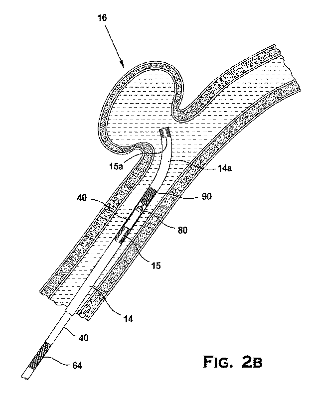
F1/F2=eμθ 式(3)
ここで、
F1は、曲がりくねった経路の長さにわたって、内部チューブと外側チューブとの間のインターフェイスの近位末端において内部部材に印加される力であり、
F2は、曲がりくねった経路の長さにわたって、内部チューブと外側チューブとの間のインターフェイスの遠位末端において外側部材によって及ぼされる抵抗力であり、
eは、対数の底であり、
μは、曲がりくねった経路の長さにわたる内部チューブと外側チューブとの間のインターフェイスの長さに沿った平均摩擦係数であり、そして
θは、曲がりくねった経路の長さに対する総くねり、すなわち、内部部材と外側部材との間の接触の角度の和(sum of angular contact)である(ラジアン)。
F 1 / F 2 = e μθ formula (3)
here,
F 1 is the force applied to the inner member at the proximal end of the interface between the inner tube and outer tube over the length of the tortuous path;
F 2 is the resistance exerted by the outer member at the distal end of the interface between the inner tube and the outer tube over the length of the tortuous path;
e is the base of the logarithm,
μ is the mean coefficient of friction along the length of the interface between the inner and outer tubes over the length of the tortuous path, and θ is the total bend over the length of the tortuous path, i.e. the inner member Is the sum of the contact angles between the outer member and the outer member (radians).
可能である最小の力伝達比(F1/F2)が、内部チューブと外側チューブとの間の移動に対して小さい摩擦損失のみが存在するように所望される。e0=1であることが周知のように、力伝達比ができるだけ小さいものであるために、μとθの積は同様に、小さい値であることが認識され得る。 The minimum force transmission ratio (F 1 / F 2 ) that is possible is desired so that there is only a small friction loss for movement between the inner and outer tubes. As is well known that e 0 = 1, it can be recognized that the product of μ and θ is similarly small because the force transmission ratio is as small as possible.
式(3)の原理および血管系解剖学的構造の知識が種々の実施形態に適用される場合、有利な力伝達比は、最大のくねりを受ける位置決めシステム10の部分における平均摩擦係数を低減することによって達成される。このことは、最大のくねりを受ける位置決めシステム10の部分(例えば、ポジショナー40の最遠位3分の1)において、特定の材料および嵌合表面の表面特性を選択することによって達成され得る。位置決めシステム10は、4000度曲がりくねった経路の長さにわたって、900度〜4000度のくねりの範囲内で、16以下の力伝達比および0.045以下の平均摩擦係数を有して作動し得る。位置決めシステム10は、4000度曲がりくねった経路の長さにわたって、2000度〜4000度のくねりの範囲内で、16以下の力伝達比および0.045以下の平均摩擦係数を有して作動し得る。
When the principle of equation (3) and knowledge of the vasculature anatomy are applied to various embodiments, an advantageous force transfer ratio reduces the average coefficient of friction in the portion of the
0.045以下の摩擦係数を提供することが可能な材料は、限定される。コード52は、50マイクロインチ未満の粗度を有するステンレス鋼コードであり得、コードライナー68は、200マイクロインチ未満の粗度を有するポリマーであり、コードライナー68およびコード52は、親水性のコーティングを有するか、またはコードライナー68とコード52との間の間隔が、2%〜10%の範囲にある濃度のステアリン酸を含む液体ポリシロキサンで充填される。コード52は、50マイクロインチ未満の粗度を有する304ステンレス鋼コードであり得、およびコードライナー68は200マイクロインチ未満の粗度を有するPTFEである。
Materials that can provide a coefficient of friction of 0.045 or less are limited. The
コード52およびコードライナー68のための材料は、コードおよびコードライナーの長さ全体に使用され得る。しかし、好ましい材料は、4000度のくねりを受けるポジショナー40の部分において提供され得、その部分は、大部分がポジショナー40の遠位3分の1である。多様な選択肢の材料がポジショナー40の近位3分の2のために利用可能であり、それはポジショナー40のこの部分が、ポジショナー40の遠位3分の1よりも小さいくねり(2000度未満)を受けるからである。ポジショナー40の近位3分の2に関して、ポジショナー40は、ポジショナー40の近位3分の2における2000度以下の曲がりくねった経路の長さにわたって、15以下の力伝達比および0.11以下の平均摩擦係数を有して作動し得る。0.11以下の摩擦係数を提供することが可能である材料は、ポジショナー40の遠位3分の1の場合ほど限定されない。ポジショナー40の近位3分の2における使用に適した好ましい材料としては、コードライナー68のためのポリエチレン、アセタール、またはフルオロポリマー、およびコード52のための50マイクロインチ未満の表面粗度を有する鋼またはポリマー材料が挙げられる。材料は、コードライナー68のためのポリエチレン、およびコード52のための50マイクロインチ未満の表面粗度を有する鋼であり得る。
The material for
有利な力伝達比はまた、位置決めシステム10の別の嵌合表面、すなわち、ポジショナーチューブスリーブ66がマイクロカテーテル14内を摺動可能に移動する場所において達成される。コード52およびコードライナー68に関して上に記載されるのと同じ式(3)の原理を適用する場合、ポジショナーチューブスリーブ66のための好ましい材料は、PTFE熱収縮材料であり、マイクロカテーテル14のための好ましい材料は、比較的より滑らかな表面を有するポリマーである。
An advantageous force transmission ratio is also achieved at another mating surface of the
可撓性
システムの長さに沿った位置決めシステムの可撓性は、システムの可撓性が、ポジショナーを制御するための操作者の能力および操作者によって操作される近位末端からのシステムの「感覚(feel)」に関係するので、システムの設計および性能に影響し得る。また、ポジショナーの遠位先端の柔軟性は、ポジショナーを所望される位置に導くための操作者の能力に関係する。システムの所望される可撓性を機械的移植物係合および係合解除システムに保持することは、特に難しい。なぜなら、システムの長さが、両方ともサイズは小さいが、システムからの移植物の係合および係合解除を引き起こすために十分に強いものであるシステムの近位末端と遠位末端との間の機械的接続を規定するからである。
Flexibility of the positioning system along the length of the system means that the flexibility of the system is the operator's ability to control the positioner and the system's “from the proximal end where it is manipulated by the operator. As it relates to “feel”, it can affect the design and performance of the system. Also, the flexibility of the distal tip of the positioner is related to the operator's ability to guide the positioner to the desired position. It is particularly difficult to maintain the desired flexibility of the system in the mechanical implant engagement and disengagement system. Because the length of the system is both small in size but strong enough to cause the engagement and disengagement of the implant from the system, between the proximal and distal ends of the system This is because the mechanical connection is defined.
位置決めシステムは、ポジショナーの近位部分における比較的剛体である構造、ポジショナーの遠位部分における比較的柔軟な構造、および近位部分と遠位部分との間の可撓性における変化を提供するポジショナーの中間における移行領域を提供することによって、適切なレベルの可撓性を達成し得る。 The positioning system provides a relatively rigid structure at the proximal portion of the positioner, a relatively flexible structure at the distal portion of the positioner, and a change in flexibility between the proximal and distal portions. By providing a transition region in the middle, an appropriate level of flexibility may be achieved.
ポジショナーの近位部分は、ポジショナーのこのセクションの長さに沿ってほとんど一定のままである可撓性(または剛性)を備え得る。近位部分の一定に近い可撓性は、チューブ構造の使用によって達成される。遠位部分および移行領域は、可撓性を増加させるチューブ構造に対する構造上の改変と、遠位方向におけるチューブ構造の長さに沿ったそれらの構造上の改変の程度の増加と、構造を強化することによってポジショナーに提供される構造上の支持との組み合わせを用いて、ある程度の柔軟性を達成する。遠位部分の可撓性は、このセクションの長さに沿って増加し、最大の柔軟性は、ポジショナーの最遠位末端の近くにおいて、またはポジショナーの最遠位末端において達成される。近位部分の一定に近い可撓性は、スカイビング加工を使用することなく、ポジショナーの完全に囲まれたチューブ構造によって達成され得る。遠位部分および移行領域の変動する可撓性特性は、スカイビング加工を有するチューブと、遠位方向におけるチューブの長さに沿ったスカイビング加工の程度の増加と、ポジショナーチューブスリーブによってポジショナーに提供される構造上の支持との組み合わせによって達成される。 The proximal portion of the positioner may be provided with flexibility (or stiffness) that remains almost constant along the length of this section of the positioner. Near-constant flexibility of the proximal portion is achieved through the use of a tube structure. The distal portion and transition region strengthen the structure with structural modifications to the tube structure that increase flexibility, increasing the degree of those structural modifications along the length of the tube structure in the distal direction By using a combination with the structural support provided to the positioner, a degree of flexibility is achieved. The flexibility of the distal portion increases along the length of this section, and maximum flexibility is achieved near the distal end of the positioner or at the distal end of the positioner. Near-constant flexibility of the proximal portion can be achieved by the fully enclosed tube structure of the positioner without using skiving. The variable flexibility characteristics of the distal part and the transition region are provided to the positioner by a tube with skiving, an increased degree of skiving along the length of the tube in the distal direction, and a positioner tube sleeve Achieved in combination with structural support.
図23Aは、図3および4に例示される実施形態のポジショナー40の可撓性を例示する(図23Aおよび23Cにおいて「3G/FX−0.012’’Prox Pusher」として識別される)。図23Aにおける水平軸(「標的部位からの距離」とラベルされる)は、ポジショナー40の長さに対応し、末端キャップ82(図2Cに例示されるように、標的部位の領域に近いか、または標的部位の領域内)は水平軸上の0点を画定し、水平軸上の各印は、末端キャップ82からの近位方向の距離を識別する。水平軸はまた、末端キャップ82が標的部位16の近くに配置される場合の、図2Aに例示されるヒトの身体における解剖学的構造上の領域に対応しており、末端キャップ82および標的部位16からの近位方向の距離を有し、その距離は、図2Aに例示されるように、ポジショナー40の近位末端が最終的にそけい部においてヒトの身体を出るまでの、図23Aにおいて識別される種々の解剖学的構造の特徴に対応する。図23Aにおける垂直軸(「モーメント」とラベルされる)は、20°のたわみを受けた場合に、その長さに沿ってポジショナー40によって提供される抵抗の量に対応する。
FIG. 23A illustrates the flexibility of the
ポジショナー40は、20°のたわみを受ける場合に、ポジショナー40は、モーメントを生じることによって、可撓性に対応するたわみに抵抗する。図23Aに例示されるように、ポジショナー40の近位部分において観測されるモーメントは、大動脈の近くに配置されるポジショナー40の部分に対して近位でほぼ一定であり、ポジショナー40のこの部分における一定に近い可撓性を示している。ポジショナー40の遠位部分において観測されるモーメントは、頸動脈に配置されるポジショナー40の部分に対して遠位方向に減少し、ポジショナー40のこの部分における遠位方向に増加する変動する可撓性を示している。また、図23Aに例示されるように、モーメントは、(ほぼ)大動脈と(ほぼ)頸動脈との間に配置されるポジショナー40の長さに対応するポジショナー40の移行領域において、ほぼ線形率(linear rate)で変化し、遠位方向におけるより少ない可撓性からより大きな可撓性へのポジショナー40のこの部分における可撓性のおおよその線形変化を示している。ポジショナー40の近位部分における一定に近い可撓性、および移行領域におけるポジショナーの可撓性のおおよその線形変化は、外側チューブ48を操作している操作者に良好な「感覚」として解釈される複合の可撓性を提供する。図23Aに例示される可撓性プロフィールはまた、脳内および頸動脈に対して遠位の曲がりくねった解剖学的構造において比較的柔軟な遠位末端を有利に提供する。比較的剛である近位末端は、操作者にポジショナー40を制御する能力を提供する。また、剛体から柔軟への最大の移行が行われる(移行領域において)ポジショナー40の部分は、ポジショナー40においてできるだけ遠位だが、解剖学的構造が脳に向かってより曲がりくねり始め、増加した柔軟性が所望される頸動脈のちょうど近位に配置される。
When the
また、図23Aに例示されるように、ポジショナー40は、ポジショナー40の長さにわたって、変動する可撓性プロフィールを提供する。ポジショナー40の近位部分において、測定されるモーメントは、ポジショナー40の近位末端と大動脈の近くに配置されるポジショナー40の部分との間(標的部位16から近位に55cmと80cmとの間)の20°のたわみにおいて0.01in−lb〜0.50in−lbであり得る。ポジショナー40の遠位部分において、測定されるモーメントは、頸動脈に配置されるポジショナー40の部分と末端キャップ82との間(標的部位16から近位に0cmと35cmとの間)の20°のたわみにおいて0.0001in−lb〜0.0100in−lbであり得る。近位部分と遠位部分との間のポジショナー40の移行領域において、測定されるモーメントは、標的部位16から35cmと50cmとの間で、20°のたわみにおいて0.001in−lbから0.100in−lbまで変化し得る。近位部分の可撓性は、20°のたわみにおいて約0.045in−lbであり得、移行領域の可撓性は、20°のたわみにおいて0.0005in−lbから0.045in−lbまで変化し、遠位部分の可撓性は、20°のたわみにおいて約0.0005in−lbである。
Also, as illustrated in FIG. 23A, the
図23Aにさらに例示されるように、ポジショナー40の可撓性は、ポジショナー40におけるモーメントの測定から決定されるように、ポジショナー40の長さにわたって特定の率で変化する。ポジショナー40の近位部分において、可撓性は、ポジショナー40の近位末端と大動脈の近くに配置されるポジショナー40の部分との間(標的部位16から近位に55cmと80cmとの間)で一定のままであり得る。ポジショナー40の遠位部分において、可撓性は、頸動脈中に配置されるポジショナー40の部分と末端キャップ82との間(標的部位16から近位に0cmと35cmとの間)で100%〜800%の率で変化し得る。近位部分と遠位部分との間のポジショナー40の移行領域において、可撓性は、標的部位16から35cmと55cmとの間で、100%〜1000%の率で変化し得る。近位部分の可撓性は、一定であり得、移行領域の可撓性は、約800%の率で変化し、遠位部分の可撓性は、約700%の率で変化する。
As further illustrated in FIG. 23A, the flexibility of the
図23Bに例示されるように、既存の熱システム、電解システム、および水圧システムの可撓性プロフィールは、図3および4に例示される実施形態の可撓性プロフィールと同等である(図23Bおよび23Cにおいて、「Cordis」は、Miami Lakes,Florida USAのCordis Corporationを指し、「MTI」は、Irvine,California USAのMicro Therapeutics,Inc.を指し、「GDC」は、Boston Scientific Corporation of Natick,Massachusetts,USAから市販されるGuglielmi Detachable CoilまたはGDCID(登録商標)Detachable Coilを指し、「Micrus」は、San Jose,California USAのMicrus Endovascular Corporationを指す)。また、図23Aと23Bとの比較から認識され得るように、例示される実施形態は、ポジショナー40近位末端と大動脈の近くに配置されるポジショナーの部分との間に、既存の熱システム、電解システム、および水圧システムよりも可撓でない近位部分を有する。
As illustrated in FIG. 23B, the flexibility profile of the existing thermal, electrolysis, and hydraulic systems is equivalent to the flexibility profile of the embodiment illustrated in FIGS. 3 and 4 (FIGS. 23B and 23C). In 23C, “Cordis” refers to the Cordis Corporation of Miami Lakes, Florida USA, “MTI” refers to Micro Therapeutics, Inc. of Irvine, California USA, and “Gt” refers to Bot. Guglielmi Detachable Coil or GDCID (registered trademark) Coil available from USA And, "Micrus" refers to San Jose, the Micrus Endovascular Corporation of California USA). Also, as can be appreciated from a comparison of FIGS. 23A and 23B, the illustrated embodiment includes an existing thermal system, electrolysis between the proximal end of the
図23Cは、0cmと40cmとの間の距離(x軸における)および0.000in−lbと0.005in−lbとの間のモーメント(y軸における)の、図23Aおよび23Bに表される情報のより接近したより詳細な図である。図23Cにおいて分かり得るように、ポジショナー40の遠位部分において、末端キャップ82から(またはそれぞれの既存のシステムの遠位末端から)0cmと35cmとの間で、観測されるモーメントは、測定がより確実ではなくなる最後の4cmに到達するまで連続的に減少する(そしてポジショナー40の可撓性は増加する)。また、図23Cにおいて分かり得るように、図23Bの既存の非機械的システムは、10cmと35cmとの間で変化せず、0cmと10cmとの間ですばやく最小のモーメントまで低減するモーメントを生み出す。既存のデバイスの最遠位10cmにおけるこの比較的急なモーメントの変化は、既存のデバイスが、それらのそれぞれの遠位部分において、連続的に変動する可撓性を有さないことを実証することが考えられる。しかし、例示される実施形態のポジショナー40は、遠位部分の長さに沿って、特に、末端キャップ82に対して近位の5cm〜35cmに沿って連続的に変化する可撓性を有する。図23Cから分かり得るように、ポジショナー40の遠位末端は、末端キャップ82から35cmと0cmとの間で100%〜800%分、例えば、約700%分、遠位方向に変化する可撓性を提供する。図23Cから分かり得るように、ポジショナー40の遠位末端は、末端キャップ82から35cmと10cmとの間で100%〜900%分、例えば、500%分減少して、遠位方向に変化するある程度の可撓性を提供する。図23Cを参照すると、既存の非機械的システムが、ポジショナー40の場合に見られるのと同じくらい有意に変化する可撓性を有する遠位部分を提供しないことが考えられ、また、既存の非機械的システムがこれらのシステムの最遠位末端から10cmと35cmとの間で変化する可撓性を有する遠位部分を提供しないことが考えられる。
FIG. 23C shows the information represented in FIGS. 23A and 23B of the distance between 0 cm and 40 cm (in the x-axis) and the moment between 0.000 in-lb and 0.005 in-lb (in the y-axis). FIG. As can be seen in FIG. 23C, at the distal portion of the
ポジショナー40の先端の可撓性は、標的部位16における移植物90の適切な位置決めに重要であり得る。図3および4に例示される実施形態の遠位先端の可撓性は、表2に示されるように、長手方向に圧縮力を受ける場合に、他のシステムと比較して、より可撓な先端を提供することが実証されている。
The flexibility of the tip of the
機械的に操作される位置決めシステムは、標的部位に到達するために十分に可撓性で小さいものだが、操作者が移植物インターフェイスの位置決めおよび機械的操作を制御することを可能にするために十分に強いままであり得る。位置決めシステムは、曲がりくねった経路にさらされるポジショナーに適した変動する摩擦係数、強度、および可撓性を有する材料および表面を利用することによって、適切なプロフィールまたはサイズを有する機械的に操作される移植物係合および係合解除システムを達成する。プッシャーチューブ42の遠位末端におけるポジショナー40の遠位末端の外径は、移植物インターフェイス80を位置決めシステム10の近位末端に接続する機械的システムからの移植物インターフェイス80の適切な操作を可能にしながら、標的部位16に到達するために十分に小さいものであり得る。プッシャーチューブ42の遠位末端におけるポジショナー40の遠位末端の外径は、304ステンレス鋼ハイポチューブまたは鋼合金に対して0.008インチ〜0.018インチの外径を有し得る。プッシャーチューブ42の遠位末端におけるポジショナー40の遠位末端の外径は、304ステンレス鋼ハイポチューブに対して0.012インチの外径を有し得る。
疲労抵抗
動脈瘤に複数の神経学的コイルを移植する場合、一般的な実践は、動脈瘤内に、動脈瘤によって作り出される空隙を占有するために十分な、および血栓の形成を促進するために十分な複数のコイルを配置することであることが考えられる。操作者の裁量内で、動脈瘤ができるだけ多くのコイルを収容する場合に、満足のいく結果が達成され得ることがまた考えられる。しかし、このような手順において、最初に移植されたコイル(複数可)が、その後のコイルの配置を干渉し得るか、または妨げることが可能である。また、すでに移植されたコイルからのこの干渉は、操作者が、動脈瘤がさらなるコイルを収容し得るかどうかを決定することをおそらく難しくし得る。少な過ぎるコイルの配置は、おそらく性能に影響し得、多過ぎるコイルの配置は、おそらく、動脈瘤の破裂または標的部位における所望される位置からコイルを押しのけることをもたらし得る。
Fatigue resistance When implanting multiple neurological coils in an aneurysm, general practice is sufficient to occupy the void created by the aneurysm within the aneurysm, and to promote thrombus formation It is conceivable to arrange a sufficient number of coils. It is also conceivable that satisfactory results can be achieved if the aneurysm accommodates as many coils as possible within the operator's discretion. However, in such a procedure, the initially implanted coil (s) can interfere with or prevent subsequent coil placement. Also, this interference from the already implanted coil may make it difficult for the operator to determine whether the aneurysm can accommodate additional coils. Too little coil placement can probably affect performance, and too much coil placement can probably result in an aneurysm rupture or pushing the coil away from the desired location at the target site.
さらなるコイルを標的部位に位置決めする場合に、動脈瘤内のすでに移植されたコイルの間にコイルを収めるために、および動脈瘤がより多くのコイルの移植を収容し得るかどうかを評価するために、操作者がさらなるコイルを行ったり来たり繰り返し移動させる(送達システムを移動させることによって)ことが、さらに考えられる。送達システムおよびさらなるコイルの繰り返される移動は、システムおよびコイルが送達カテーテル内を摺動可能に移動する場所、ならびにさらなるコイルがすでに移植されたコイルに接触する場所で、システムおよびコイルに摩擦を経験させることがまた考えられる。システムおよびコイルの繰り返される移動からの摩擦は、システムとコイルとの間の接続点に著しい応力を経験させ得、繰り返される行ったり来たりの移動と組み合わされる場合、おそらく材料疲労および接続点の断裂を引き起こし、システムからのコイルの時期尚早な係合解除をもたらすことが考えられる。さらなるコイルを固定して、もしくはしっかりと係合する既存の送達システム、またはシステムに対してコイルの自由な移動もしくは回転を妨げる既存の送達システムは、システムおよびコイルの繰り返される行ったり来たりの移動に対する応力の発達を可能にすることがさらに考えられる。 To position the coil between the already implanted coils in the aneurysm and to assess whether the aneurysm can accommodate more coiled implants when positioning additional coils at the target site It is further envisaged that the operator repeatedly moves the coil back and forth (by moving the delivery system). Repeated movement of the delivery system and further coil causes the system and coil to experience friction where the system and coil move slidably within the delivery catheter, and where the further coil contacts the already implanted coil. It is also possible. Friction from repeated movements of the system and coil can cause significant stress at the connection point between the system and the coil, and when combined with repeated back and forth movements, possibly material fatigue and connection point rupture And premature disengagement of the coil from the system. Existing delivery systems that secure or securely engage additional coils, or existing delivery systems that prevent free movement or rotation of the coil with respect to the system, are repeated reciprocating movements of the system and coil. It is further conceivable to allow the development of stress on the.
種々の実施形態のポジショナーは、移植物インターフェイスによって画定される制限内で、ポジショナーに対する移植物の拘束のない移動を可能にすることによって、ポジショナーと移植物との間のインターフェイスにおける応力の発達を避けるか、または最小化する。移植物インターフェイスの応力の発達は、ボール、棒、および移植物が、位置決めシステムの軸に対して軸方向および半径方向に移動でき、棒または移植物の軸のまわりを回転することができ、および移植物が位置決めシステムの軸に対してある角度であるように角度をなして移動することができるので、最小化されるか、または避けられる。 The positioners of various embodiments avoid stress development at the interface between the positioner and the implant by allowing unconstrained movement of the implant relative to the positioner within the limits defined by the implant interface. Or minimize. The stress development of the implant interface is such that the ball, rod, and implant can move axially and radially relative to the axis of the positioning system, can rotate about the axis of the rod or implant, and Since the implant can be moved at an angle such that it is at an angle with respect to the axis of the positioning system, it is minimized or avoided.
図13を参照すると、移植手順中に行ったり来たり(または押す−引っ張る)の移動を受ける場合に、ポジショナー40の近位移動(または引っ張り)は、移植物インターフェイス80がボール96を係合し、近位方向にボール96を引っ張り、移植物90を引っ張ることを引き起こし、ポジショナー40の近位移動は、移植物90が近位に向けられた移動に抵抗する場合に、マイクロカテーテル14の内側との接触またはすでに移植された移植物との接触からの摩擦に起因して、ボール96および棒94における応力を引き起こし得る。しかし、ボール96および棒94は、末端キャップ82内を移動することができるので、移植物90は、ポジショナー40に対する移植物90の曲がりもしくは方向変化からの応力の発達を防ぐ配向、角度、または回転位置をとるか、またはそれを最小化する配向、角度、または回転位置をとることができる。
Referring to FIG. 13, the proximal movement (or pull) of the
図12を参照すると、ポジショナー40の遠位移動(または押し)は、軸方向に向けられた力をボール96にも棒94にも印加することなく、移植物インターフェイス80の遠位表面(末端キャップ82)が移植物90の近位表面を係合し、遠位方向に移植物90の近位表面を押し、移植物90自体を押すことを引き起こす。ポジショナー40から移植物90に与えられる力の全てまたは大部分が、ボール96も棒94も巻き込むことなく移植物90に直接与えられるので、ボール96および棒94は従って、移植物90が遠位方向に移動する場合に、有意な応力にさらされないが、末端キャップ82との接触またはポジショナー40との接触によってボール96または棒94に印加されるいくらかの半径方向に向けられた力が存在し得る。ポジショナー40および移植物90の遠位移動において、移植物90は、末端キャップ82、マイクロカテーテル14の内側、またはすでに移植された移植物との、移植物90の接触からもたらされる力に応答して、配向または回転位置をとることが可能であるままである。また、移植物90が末端キャップ82に接触するので、操作者は、動脈瘤内もしくはすでに移植された移植物の中に、移植物90を挿入するための試み、またはそれを収めるための試みからもたらされる抵抗の程度に対する触感を提供される。
Referring to FIG. 12, distal movement (or pushing) of the
表3に示されるように、測定される場合に、棒94とポジショナー40との間の係合は、既存のシステムに接続される移植物間のインターフェイスよりも大きな引張力に耐え得ることが観測されている(「ポジショナー/移植物インターフェイス」は、記載される実施形態を指し、「Sapphire/NXT/Nexus」は、Plymouth,Minnesota USAのEV3,Inc.から市販されるSapphireTM、NXTTM、およびNexusTM製品を指し、「GDC」は、Natick,Massachusetts,USAのBoston Scientific Corporationから市販されるGuglielmi Detachable CoilまたはGDC(登録商標)Detachable Coilを指す)。
As shown in Table 3, it has been observed that when measured, the engagement between the
少なくとも図3および4に例示される実施形態は、包装から取り去られる場合に、および患者への挿入前に、例えば、図8Aに例示されるように、すでに係合された配向にあり得るコイル位置決めシステム10を提供する。例示されるポジショナー40および移植物90は従って、包装から出してすぐに使用できるシステムを提供し、コイルを配備する前に行われるような医学手順に共通する必要なステップ(例えば、患者へのマイクロカテーテルの挿入およびマイクロカテーテルの中への送達システムの挿入)を受ける。
少なくとも図3および4に例示される実施形態はまた、コイルの取り外しを開始し完了するための中間プロセスなく、取り外しメカニズムの始動と送達システムからの移植物の取り外しとを直接接続するコイル位置決めシステムを提供する。図3〜4および8A〜8Cに例示されるように、スライド50とコード52との間の直接接続は、スライダー50の移動がコード52をポート84から離して移動させることを引き起こし、取り外された状態を達成する。なぜなら、それにより、ボール96がポート84を自由に通過するので、移植物90は、もはやポジショナー40によってしっかりと保持されていないからである。また、例示される移植物90のコイル構造は、コイル構造が標的部位16の解剖学的構造に対して伸びるか、または順応するので、ポート84を通るボール96の移動をさらに容易にし、そのことは、移植物90が末端キャップ82から離れて遠位に移動することを引き起こし、それにより、ポート84を通るボール96の移動を容易にする。例示される実施形態は、約15秒の包装から出す調製時間および1秒未満の取り外し時間を達成し得る。
The embodiment illustrated at least in FIGS. 3 and 4 also provides a coil positioning system that directly connects the initiation of the removal mechanism and removal of the implant from the delivery system without an intermediate process to initiate and complete coil removal. provide. As illustrated in FIGS. 3-4 and 8A-8C, the direct connection between the
例示される実施形態の調製時間および取り外し時間は、標的部位において、移植物の迅速で効率的な配備を可能にするシステムを提供することが考えられる。有利な調製時間および取り外し時間は、位置決めシステムを調製するため、および手順の効率を有利に増加させるために必要とされる時間の長さを低減し、それにより、従事者が侵襲的な医学手順中に他の職務に専心することを可能にする。 The preparation and removal times of the illustrated embodiments are believed to provide a system that allows for rapid and efficient deployment of the implant at the target site. Advantageous preparation and removal times reduce the length of time required to prepare the positioning system and advantageously increase the efficiency of the procedure, thereby enabling the practitioner to perform an invasive medical procedure Allows you to devote yourself to other duties.
側壁の孔
参照は、2010年7月8日に公開された米国特許公開第2010/0174269号、および対応する2009年7月7日に出願された米国出願第12/498,752号に対してなされ、その全体は、本明細書中であたかも完全に明記されるように、参考として援用される。
Sidewall Holes Reference is made to US Patent Publication No. 2010/0174269, published July 8, 2010, and corresponding US Application No. 12 / 498,752, filed July 7, 2009. The entirety of which is hereby incorporated by reference as if fully set forth herein.
図29〜33は、取り外しシステムの実施形態を例示する。図29、32、および33は、本明細書中で移植物90とも称される塞栓コイル206を挿入ツール214から取り外すための連続するステップ後の取り外しシステム200を例示する。図29から始めると、挿入ツール214の遠位末端の側面立面断面図が示される。挿入ツール214は、本明細書中でチューブ42とも称される細長いプッシャーチューブ216、遠位開口部219を有する管状遠位先端218、および側壁204であって、そこを通る、本明細書中で腔86とも称される管腔208を画定する、側壁204を含む。遠位開口部219は、チューブ216の断面寸法に実質的に類似する断面寸法、またはポート84に関して開示されるような、チューブ216の断面寸法よりも小さい断面寸法を有し得る。プッシャーチューブ216は、同じ材料から構成され、ポジショナーチューブ42について以前に記載されたものと同じプロセスを用いて作られ得る。管状遠位先端218は、金属、セラミック、ポリマー、または当該分野において公知である他の材料から構成され得る。プッシャーチューブ216は、溶接加工、接着剤、クリンピング加工、または他の手段によって管状遠位先端218に永久的に付着され(affixed)得る。1つ以上の実施形態において、プッシャーチューブ216の遠位末端は、管状遠位先端の近位末端内のソケットの中に挿入され、エポキシ接着剤によって付着される。側壁204は、パドル240、パドル240の一部分を取り囲んでいる部分的な孔244、および肩246を画定するために切断されるか、成形されるか、または他の方法で構成される。パドル240および部分的な孔244は、種々の大きさおよび/または形のものであり得る。パドル240に適した形の例は、図30における上面図において見られ得、その図はまた、システム200の配備前の、本明細書中でボール96とも称されるボール232の可能な位置を明らかにする。ボール232の他の形、位置、および配向が企図され、卵の形および多面体が挙げられるが、これらに限定されない。下でより詳細に説明されるように、コイル206を放出するためのシステム200の配備前に、ボール232は、管腔208内で、軸方向の、回転の、および旋回(傾斜(tilting))による移動の自由度を有する。例えば、ボール232は、コイル移植物206が、(i)細長いプッシャーチューブ216に対して軸方向に移動すること、(ii)細長いプッシャーチューブ216の長手方向の軸に対してある角度の範囲内で、ボール232のまわりに傾くこと、および(iii)プルワイヤー226がボール232に接触している間に、その自らの長手方向の軸のまわりを回転することのうちの少なくとも1つを行うように構成されているように、管腔208内に配置され得る。ボール232の正確な位置は、結果的に、図30において例示されるものから変化し得る。
Figures 29-33 illustrate embodiments of removal systems. 29, 32, and 33 illustrate the
また、整列部材228が、側壁204において、切断されるか、他の方法で構成されるか、または配置され、パドル240と対向して図29の例に示される。図31におけるデバイスの底面図から見られるように、整列部材は、側壁204からの輪状の切断として例示される。代替的にまたは組み合わせて、整列部材は、バンドを画定するために側壁の中に1つ以上の円周方向の切断および/または長手方向の切断を配置し、管腔の中へ内方にバンドを曲げることによって形成され得る。整列部材228は、例えば、フック、タブ、または本明細書中でコード52とも称されるプルワイヤー226の位置決めをガイドするための任意の他の適切な構造であり得ることが認識される。プルワイヤー226は、同じ材料から構成され、コード52について以前に記載されたものと同じプロセスを用いて作られ得る。いくつかの実施形態において、プルワイヤーは、挿入ツール214の遠位領域または他の領域における増加した可撓性および他の利点を提供するために、1つ以上の先細セグメント226Aおよび226Bから構成され得、先細セグメント226Aおよび226Bは、プルワイヤーと壁204の内部表面における粗度またはレッジとの間の滑らかな摺動に対する干渉を排除する。先細セグメント226Aまたは226Bは、第一の断面寸法を有するプルワイヤー226の第一のセグメントから第二の断面寸法を有するプルワイヤー226の第二のセグメントまでの1つ以上の滑らかな移行または中断された移行を提供し得る。例えば、セグメントは、第一の断面寸法から第二のより小さな断面寸法まで先細になり得る。先細は、近位方向または遠位方向に起こり得る。プルワイヤー226は、整列部材228内で軸方向に移動可能であるが、整列部材228は、意図されない円周方向の、プルワイヤー226の移動を防ぐことを助ける。
Also, the
システム200を配備するための調製において、プルワイヤー226は、整列部材228を通って、管腔208を通って、ボール232またはコイル206と同じくらい遠くに到達するまで装填される。コイル206を装填する前に、先細にされ得るプルワイヤー226は、ボール232の装填を可能にするために挿入ツール214の遠位末端を通って通され、次にコイル206を放出可能に保持するために後退させられるか、前進させられ得る。プルワイヤー226は、整列部材228を介して、遠位先端218内に位置決めされ、管腔208を占有する場合、パドル240に対してボール232を促し、ボール232は、孔244内で移動の自由度を有する。部分的な孔244は、パドル240が側壁204の面からわずかに外れるように促されることを可能にし、パドル240は次いで、ボール232にいくらかの圧力をかける。遠位方向におけるボール232の軸方向運動は、肩246によって防止され、それにより、ボール232が遠位先端218を出ることを防ぐ。ボール232は、システム200の配備前に挿入ツール214の遠位先端内に保持されるが、ボール232は、操作者によるプルワイヤー226の後退前に、挿入ツール214の遠位先端218内での軸、回転、および旋回の移動の自由度を有利に有する。
In preparation for deploying
図32に示されるように、取り外しシステム200の配備中、プルワイヤー226は、ボール232の近位に後退させられる。代替的にまたは組み合わせて、挿入ツール214は、プルワイヤー226に対して遠位に移動させられる。一旦プルワイヤー226が、ボール232の近位にあると、ボール232は、パドル240によって挿入ツール214の管腔208の中に促される。ボール232の軸方向移動は、もはや、肩246によって遠位方向に制限されず、ボール232(およびいくつかの実施形態において、コイル206)は、遠位先端218を自由に出る。図33は、遠位先端218から出た後のコイル206を例示する。
As shown in FIG. 32, during deployment of the
図34は、上の図29〜33に対して記載される実施形態の同じ原理に概ね従って動作する同様の取り外しメカニズムを例示する。実施形態に従って、取り外しシステム300は、挿入ツールからの塞栓コイル306の取り外しのためのメカニズムを提供する。挿入ツールは、細長いプッシャーチューブを含み、側壁の孔の少なくとも一部分を覆うパドル340を有する。図34に例示される実施形態において、パドル340は、挿入ツールの長手方向の軸に対して平行または横(例えば、垂直)に配向され得る。あるいは、孔はパドル340を一切取り囲まず、パドル340は、半径方向に外へ向かって突き出るチューブの一部分であり得、プルワイヤー326と接触する場合に、その中に取り付け部材332が存在し得る凹を提供する。パドル340の他の構成も、本開示に従って可能である。塞栓コイル306は、初めはチューブ内に、例えば、パドル340において、またはパドル340の近くに存在する取り付け部材332に取り付けられる。取り付け部材332は、多様な形(球形、卵形、多面体、円柱形、等が挙げられる)のうちのいずれかであり得る。また、整列部材328が、側壁において切断されるか、他の方法で構成されるか、または配置され、パドル340と対向して図34の例に示される。
FIG. 34 illustrates a similar removal mechanism that operates generally in accordance with the same principles of the embodiments described for FIGS. 29-33 above. According to embodiments, the
実施形態に従って、システム300を配備するための調製において、プルワイヤー326は、整列部材328を通って、取り付け部材332に到達するまでか、コイル306と同じくらい遠くに到達するまでか、またはコイル306を超えたところに到達するまで装填される。プルワイヤー326は、パドル340に対して、または凹の中に取り付け部材332を促す(示されていない)。遠位方向における取り付け部材332の軸方向運動は、パドル340または凹に対して遠位であるチューブの一部分によって防止され、それにより、取り付け部材332がチューブの遠位末端から出ることを防ぐ。取り外しシステム300の配備中、プルワイヤー326が、取り付け部材332の近位に後退させられ、次に、取り付け部材332の軸方向移動は、もはや、遠位方向において制限されず、取り付け部材332(およびいくつかの実施形態において、コイル306)は、チューブを自由に出る。
According to embodiments, in preparation for deploying the
管腔断面プロフィール
いくつかの実施形態に従って、図35A、35B、36Aおよび36Bに示されるように、細長いプッシャーチューブ216、またはその一部分(例えば、管状遠位先端218)は、その内壁が、チューブ216の長手方向の軸に対するプルワイヤー226の側方運動を防ぐか、制限するか、または低減するために、非円形プロフィールを有する管腔を画定するように予形成され得る。例えば、図35Aに示されるように、管腔を画定している内壁のある領域は、遠位先端218の長手方向の軸に対して垂直である面において非円形の断面形状を有し、その面は、プルワイヤー226とボール232との間の接触の点を横切っている。内壁は、例えば、押出し、ヒートセット、スエージ加工、ダイフォーミング、または他の技術を用いて形成され得る。
Lumen Cross-sectional Profile According to some embodiments, as shown in FIGS. In order to prevent, limit or reduce the lateral movement of the
いくつかの実施形態に従って、遠位先端218の壁の厚さは変動し得る。例えば、図35Aに示されるように、非円形の断面寸法を有する管腔は、プルワイヤー226、管腔内のボール232の部分、または他の構造のいずれによっても占有されない空隙Vを画定し得る。ボール232が、孔244または凹を通って少なくとも部分的に延在する場合に、空隙が、管腔内に残っているボールおよびプルワイヤー226の部分と管腔の壁の表面との間の開いた空間によって画定される。
According to some embodiments, the wall thickness of the
いくつかの実施形態に従って、図35Bに示されるように、細長いプッシャーチューブ216、またはその一部分(例えば、管状遠位先端218)は、空隙のサイズを低減するか、または空隙を排除するために、そうでなければ空隙であるところをくぼませられ得る。遠位先端218は、所望される管腔の形を保つチューブの内側で形成マンドレルと協力して製造され得る。この場合、遠位先端218の外部表面は、プルワイヤー226の側方運動を制限するために、遠位先端の遠位領域を少なくとも覆う凹形領域217Aと遠位先端の内部表面上に対応する凸形領域217Bとを有する。くぼませられたチューブは、例えば、上に列挙された技術、クリンピング加工、または他の技術を用いて形成され得る。
According to some embodiments, as shown in FIG. 35B, an
いくつかの実施形態に従って、図36Aに示されるように、プルワイヤー226の近くの空隙はまた、チューブ216の長手方向の軸に対するプルワイヤー226の側方運動を防ぐか、制限するか、または低減するために、空間占有材料227を用いて充填され得る。
In accordance with some embodiments, as shown in FIG. 36A, the air gap near the
あるいは、図36Bに示されるように、変動する壁の厚さを有する遠位先端218は、上に列挙される技術によって形成され得る。変動する壁の厚さを有する遠位先端218は、実質的に円形または非円形の断面寸法の外側プロフィール、および円形または非円形の断面寸法の内部プロフィールを提供し得る。内部プロフィールは、外側プロフィールよりも小さいものであり得、2つのプロフィールは、共通の中心または中心軸を共有しているか、または共有していない。例えば、図36Bに示されるように、内部プロフィールは、プルワイヤー226近くの遠位先端218の領域の厚さが、プルワイヤー226に対向する遠位先端218の領域よりも大きいものであるように、外側プロフィールの中心点から離れて中心点を有するように構成され得る。内部プロフィールおよび外側プロフィールの各々は、チューブ216の長さの一部分の長さに沿って変動しても、一定であってもよい。例えば、内部プロフィールは、チューブ216の遠位セグメントに沿った第一の構成と、チューブ216の近位セグメントに沿った第二の構成とを有し得る。同様に、外側プロフィールは、チューブ216の遠位セグメントに沿った第一の構成と、チューブ216の近位セグメントに沿った第二の構成を有し得る。上記構成のうちの任意のものは、本明細書中に記載され得る。
Alternatively, as shown in FIG. 36B, a
いくつかの実施形態に従って、チューブ216の管腔を画定する内壁は、ボール232、および半月形または他の非円形の断面形状の領域を有するプルワイヤー226を受け取るために形作られ得る。例えば、チューブ216の管腔は、管腔内に一緒に配置される場合に、ボール232およびプルワイヤー226が順応する管腔サイズおよび形を提供し得る。
In accordance with some embodiments, the inner wall defining the lumen of
いくつかの実施形態に従って、非円形の断面の幾何学的形状を有するチューブ216の管腔を画定する内壁は、プルワイヤー226およびボール232の周り、ならびにプルワイヤー226とボール232との間のチューブ216の管腔における空隙を低減するか、または排除し得る。この構成は、プルワイヤー226の側方運動、特に、製造の許容差の制限に起因する側方運動を低減し、それにより、ボール232の意図されない時期尚早な放出を低減する。
In accordance with some embodiments, the inner wall that defines the lumen of a
プルワイヤーの幾何学的形状
いくつかの実施形態に従って、図37に示されるように、プルワイヤー226、またはその一部分は、非円形の断面形状を有し得る。例えば、プルワイヤー226の領域は、細長いプッシャーチューブ216の長手方向の軸に対して垂直である面において非円形の断面形状を有し得、その面は、プルワイヤー226とボール232との間の接触の点を横切っている。領域の断面形状は、他の方法でボール232によって占有されない管腔の実質的な部分を、少なくとも充填し得る。例えば、図37に示されるように、プルワイヤー226の領域は、実質的に半月形の形をした断面の幾何学的形状を有し得る。プルワイヤー226の領域は、ボール232に対して向いている凹の第一の側面を有し得る。第一の側面は、ボール232と接触し得る。プルワイヤー226の領域は、ボール232から離れる方に向いている凸の第二の側面を有し得る。第二の側面は、チューブ216の壁と接触し得る。
Pull Wire Geometries According to some embodiments, as shown in FIG. 37, the
半月形の断面形状をしたワイヤーは、例えば、スエージ加工、クリンピング加工、スタンピング、鍛造、めっき、EDM、溶接加工、グラインディング、または他の技術によって形成され得る。いくつかの実施形態に従って、プルワイヤー226の遠位部分は、非円形の断面を有し、プルワイヤー226の近位部分は、実質的に円形の断面を有する。いくつかの実施形態に従って、プルワイヤー226の長さ全体は、非円形の断面を有する。いくつかの実施形態において、凹側面の曲率半径は、ボール232の湾曲の半径に対応し得る。いくつかの実施形態において、ボール232に対するプルワイヤー226の摩擦を低減するために、凹側面の湾曲の半径は、2つの間の接触が、プルワイヤー226の凹表面全体を覆う接触を有するのではなく、2つの線または点に限定されるように、ボール232の湾曲の半径よりも小さいものであり得る。いくつかの実施形態において、ボール232に対するプルワイヤー226の摩擦を低減するために、凹側面の湾曲の半径は、2つの間の接触が、プルワイヤー226の凹表面全体を覆う接触を有するのではなく、点に限定されるように、ボール232の湾曲の半径よりも大きいものであり得る。
A wire with a half-moon shaped cross-section can be formed, for example, by swaging, crimping, stamping, forging, plating, EDM, welding, grinding, or other techniques. According to some embodiments, the distal portion of the
いくつかの実施形態に従って、非円形の断面の幾何学的形状を有するプルワイヤー226は、プルワイヤー226およびボール232の周り、ならびにプルワイヤー226とボール232との間のチューブ216の管腔において、空隙を低減または排除し得る。この構成は、プルワイヤー226の側方運動、特に、製造の許容誤差の制限に起因する側方運動を低減し、それにより、ボール232の意図されない時期尚早な放出を低減する。
In accordance with some embodiments, the
無外傷パドル
いくつかの実施形態に従って、パドル240は、パドル240が作製される材料の弾性限界を超えてパドル240を過剰に曲げることによって、チューブ216の中心軸に向かって内方に湾曲され得、その結果、パドル240は湾曲された内方位置における永久的な配置を獲得する。図38Aおよび38Bに示されるように、パドル240は、孔244の縁においてチューブ216(例えば、管状遠位先端218)から延びることによって、孔244の少なくとも一部分を覆う。いくつかの実施形態に従って、パドル240のどの部分も、チューブ216の外径よりも大きいチューブ216の軸からの半径方向の範囲に延在しない。いくつかの実施形態に従って、パドル240の一部分(例えば、近位部分)は、チューブ216の外径よりも大きいチューブ216の軸からの半径方向の範囲に延在する。いくつかの実施形態に従って、パドル240の一部分(例えば、遠位部分)は、チューブ216の外側表面の下で半径方向の距離であるチューブ216の長手方向の軸に向かって内方に延在する。この内方への方向変化または湾曲は、曲げること、ヒートセット、または他の手段によって提供され得る。適用される曲がりの量は、必要に応じて、製造中の内部マンドレルの使用と協力して、ダイ、クリンピング加工、または他の技術によって制御され得る。
Atraumatic Paddle According to some embodiments, the
いくつかの実施形態に従って、パドル240は、パドル部分240が所望される湾曲された内方位置にあるか、または所望される湾曲された内方位置近くにある間に、チューブ216の少なくともパドル部分240に熱を印加することによって、湾曲された内方位置にヒートセットされ得る。熱の局所的な印加は、例えば、レーザーエネルギー、CO2レーザーエネルギー、加熱されたダイ、RF加熱、または他の技術を用いて適用され得る。印加される曲がりの量は、必要に応じて、製造中の内部マンドレルの使用と協力して、加熱されたダイ、熱伝導成形、または他の技術によって制御され得る。形状記憶特性を有する材料(ニチノール等)は、ヒートセット技術に特に適している。
In accordance with some embodiments, the
回転可能なストッパー
いくつかの実施形態に従って、図39、40A、および40Bに示されるように、プルワイヤー226は、ストッパー226Aを含み得、その長さに沿って拡大された領域を形成する。ストッパー226Aは、プルワイヤー226の他の部分の断面形状およびサイズと異なる断面形状およびサイズを有し得る。例えば、プルワイヤー226は、ストッパー226Aに対して近位または遠位である部分において、実質的に円形の断面形状を有し得る。ストッパー226Aは、非円形の断面形状(正方形、長方形、三角形、楕円形、または他の形等)を有し得る。
Rotatable Stopper According to some embodiments, as shown in FIGS. 39, 40A, and 40B, the
いくつかの実施形態に従って、プルワイヤー226は、管腔の縮小された部分229を通って管腔内で延び得る。プルワイヤー226は、プルワイヤー226の部分が、チューブ216の側壁に対して、またはチューブ216の側壁から離れて配置されることを可能にするために、縮小された部分229内に整列され得る。プルワイヤー226は、チューブ216内で任意の長さを延び、孔内もしくは孔の近くにあり得るボール232、またはチューブ216の管腔内に他の方法で配置され得るボール232に接触し得る。縮小された部分229は、チューブ216(例えば、管状遠位先端218)の壁から延びる整列部材228によって形成され得る。代替的にまたは組み合わせて、縮小された部分229は、管腔の他の部分に対して先細の断面寸法または縮小された断面寸法を有するチューブ216の管腔の一部分であり得る。いくつかの実施形態に従って、ストッパー226Aは、縮小された部分229に対して遠位であるプルワイヤー226上に配置され得る。プルワイヤー226は、ストッパー226Aに対して近位または遠位の部分に沿って断面プロフィールを有し得、ストッパー226Aは、異なる断面プロフィールを有する。例えば、プルワイヤー226は、ストッパー226Aに対して近位または遠位の部分に沿って実質的に円形の断面プロフィールを有し得、ストッパー226Aは、その長さに沿って非円形の断面プロフィールを有し得る。縮小された部分229は、ストッパー226Aの断面プロフィールに対応する断面プロフィールを有し得る。例えば、縮小された部分229の断面プロフィールは、ストッパー226Aの断面プロフィールに幾何学的形状的に類似し得る。さらなる例として、縮小された部分229の断面プロフィールは、ストッパー226Aの断面プロフィールと実質的に同じ形を有し得る。
According to some embodiments, the
ストッパー226Aの第二の断面プロフィールは、プルワイヤー226の近位部分の少なくとも1つの断面寸法を超える少なくとも1つの断面寸法を有し得る。ストッパー226Aの第二の断面プロフィールは、それを通ってプルワイヤー226が延在する縮小された部分229の少なくとも1つの断面寸法を超える少なくとも1つの断面寸法を有し得る。
The second cross-sectional profile of the
いくつかの実施形態に従って、図40Aに示されるように、ストッパー226Aが縮小された部分229に対して第一の回転状態にある間、縮小された部分229を通るストッパー226Aの移動は制限される。いくつかの実施形態に従って、ストッパー226Aが縮小された部分229に対して第二の回転状態の間、縮小された部分229を通るストッパー226Aの移動は許される(図40B)。ストッパー226Aの回転状態が、使用者によって制御される場合、縮小された部分229を通るストッパー226Aの移動、およびプルワイヤー226の近位移動は、ストッパー226Aの所与の回転状態が使用者によって制御可能に選択されるまで、低減されるか、防止され得る。従って、プルワイヤー226の時期尚早の近位移動は、低減されるか、排除され得、それにより、プルワイヤー226の意図されない長手方向の後退、およびボール232の時期尚早な放出を低減する。
According to some embodiments, as shown in FIG. 40A, movement of the
ストッパー226Aは、溶接加工、電着、管状構成要素を取り付けること(例えば、溶接加工、ろう付け、はんだ付け、もしくは接着による)、または他の手段等によって、材料をプルワイヤー226に加えることによって形成され得る。代替的にまたは組み合わせて、ストッパー226Aは、グラインディング、スエージ加工、クリンピング加工、EDM、または他の手段等によって、材料をプルワイヤー226から除去することによって形成され得る。ストッパー226Aは、2つの間の摩擦接続(例えば、締りばめ)を形成するために、補足の構成要素をスエージ加工またはクリンピング加工した後、プルワイヤー226を覆う補足の構成要素を摺動させることによって形成され得る。ストッパー226Aは、ストッパー226Aがワイヤーの軸に対して垂直である方向においてワイヤーの直径よりも広く、またワイヤーの軸に対して垂直である異なる方向においてワイヤーの直径よりも狭いものであるようにプルワイヤー226を平らにするために、プルワイヤー226の領域を圧印加工することによって形成され得る。
いくつかの実施形態に従って、図39に示されるように、ストッパー226Aは、整列部材228の遠位表面231に対して平行である近位表面230を有し得、その結果、遠位表面231がプルワイヤー226の軸に対して垂直でない場合に、プルワイヤー226は、整列部材228に対して好ましい回転状態で整列する傾向にある。上記回転状態は、ストッパーが整列部材228における穴を通過できない配向であり得る。整列部材228は、プルワイヤー226の軸に対して多くの角度をなして配向され得る。いくつかの実施形態において、45度〜135度の角度が企図される。
According to some embodiments, as shown in FIG. 39, the
孔のインターフェイス
いくつかの実施形態に従って、図41〜42に示されるように、ボール232は、少なくとも部分的にチューブ216(例えば、管状遠位先端218)の孔244の中に延在するように構成されている突起部232Aを有し得る。ボール232上の突起部232Aは、正方形、長方形、三角形、楕円形、または他の形のような断面形状を有し得る。突起の高さは、変動し得るが、突起部232Aが、位置決めされた送達中に、ステント、カルシウム沈着、他の管腔粗度に対して望ましくなくひっかかり得るチューブの外側表面を超えて延在しないように、望ましくはチューブ216の壁厚さと等しい。
Hole Interface According to some embodiments, as shown in FIGS. 41-42, the
突起部232Aは、溶接加工、電着、管状構成要素を取り付けること(例えば、溶接加工、ろう付け、はんだ付け、もしくは接着による)、または他の手段等によって、材料をボール232に加えることによって形成され得る。代替的にまたは組み合わせて、突起部232Aは、グラインディング、スエージ加工、クリンピング加工、EDM、または他の手段等によって、ボール232から材料を除去することによって形成され得る。突起部232Aは、ボールの表面から突起部を生じさせるために、ボール232のある領域を圧印加工することによって形成され得る。いくつかの実施形態において、突起部232Aの製作により、ボール232は変形され、その結果、突起部232Aを考慮しないボール232は、もはや球形ではなく、むしろ平らにされた形、卵の形、または他の形を有する。
いくつかの実施形態に従って、図41に示されるように、突起部232Aの1つ以上の突起233は、カテーテルの軸に対して実質的に垂直であることが企図される。いくつかの実施形態に従って、図42に示されるように、1つ以上の突起233は、カテーテルの軸と非直交の角度を形成し得る。このような角度は、約60度と約120度との間であり得る。いくつかの実施形態において、図42に示されるように、ボール232から最も遠い表面における突起部232Aの幅は、ボール232との接触の領域における突起部232Aの幅よりも広く、その結果、チューブ216の肩246は、突起部232Aに対して押しつけられる場合に、孔244内でのより大きな係合の位置までボール232を変位させる傾向があり、それによりボール232の確保を高める。肩246の表面は、ボール232の確保を高めるために、突起233の表面に対して平行であり得る。
In accordance with some embodiments, as shown in FIG. 41, it is contemplated that one or
「含む(comprise)」が、特許請求の範囲において、推移用語として用いられる場合に解釈されるように、用語「含む(include)」、「有する」、または同様のものが本記載または特許請求の範囲において使用される程度まで、そのような用語は、用語「含む(comprise)」と同様の様式で包括的であることが意図される。 The terms “include”, “having”, or the like are intended to be interpreted in this description or in the claims, as “comprise” is construed when used as a transition term in the claims. To the extent used in the scope, such terms are intended to be inclusive in a manner similar to the term “comprise”.
語句「例示的な」は、「例、実例、または例示として役立つこと」を意味するために本明細書中で使用される。「例示的な」として本明細書中に記載される任意の実施形態は、必ずしも他の実施形態よりも好ましいまたは有利であるものとして解釈されない。 The phrase “exemplary” is used herein to mean “serving as an example, instance, or illustration”. Any embodiment described herein as "exemplary" is not necessarily to be construed as preferred or advantageous over other embodiments.
単数形における要素に対する参照は、具体的に言及されない限り、「1つおよび1つのみ」を意味することを意図せず、むしろ「1つ以上」を意味する。男性代名詞(例えば、彼の)は、女性および中性(例えば、彼女のおよびその)を含み、逆もまた同様である。用語「いくつか」は、1つ以上を指す。下線を引かれたおよび/またはイタリック体で印刷された見出しおよび小見出しは、便宜のためにのみ使用され、本技術を限定せず、本技術の記載の解釈に関して参照されない。当業者に公知であるか、または後に公知となる本開示を通して記載される種々の構成の要素に対する、全ての構造上および機能上の等価物は、本明細書中で参考として明白に援用され、本技術によって包含されることが意図される。さらに、本明細書中に開示されるものはどれも、そのような開示が上の記載においてはっきりと記載されるかどうかに関わらず、公開の目的であることは意図されない。 References to elements in the singular are not intended to mean “one and only one”, but rather mean “one or more”, unless specifically stated otherwise. Male pronouns (eg, his) include female and neutral (eg, her and its), and vice versa. The term “some” refers to one or more. Headings and subheadings that are underlined and / or printed in italics are used for convenience only, do not limit the present technology, and are not referenced for interpretation of the description of the present technology. All structural and functional equivalents to the elements of the various configurations described throughout this disclosure that are known to those skilled in the art or later become known are expressly incorporated herein by reference, It is intended to be encompassed by the present technology. Moreover, nothing disclosed herein is intended to be a public purpose, regardless of whether such disclosure is expressly recited in the above description.
本発明の特定の局面および実施形態が記載されているが、これらは、例としてのみ表され、本発明の範囲を限定することは意図されない。実際に、本明細書中に記載される新規の方法およびシステムは、その趣旨から外れることなく、多様な他の形態で具体化され得る。添付の特許請求の範囲およびそれらの等価物は、本発明の範囲および趣旨内に入るような形態または改変を含むことが意図される。 While specific aspects and embodiments of the invention have been described, they are presented by way of example only and are not intended to limit the scope of the invention. Indeed, the novel methods and systems described herein may be embodied in a variety of other forms without departing from the spirit thereof. It is intended that the appended claims and their equivalents include forms or modifications that fall within the scope and spirit of the present invention.
Claims (15)
長手方向の軸と、該軸に沿って管腔を画定する壁と、内部断面寸法および遠位末端を有する遠位部分とを有する管状部材と、
拡大された近位末端を有するコイル移植物と、
該管腔内に延在するコアワイヤーであって、該コアワイヤーは、該拡大された末端に点で接触し、該コアワイヤーは、該長手方向の軸に対して横断する面内にある断面を有する領域を含み、該領域は、該点を横切り、実質的に半月形状である、コアワイヤーと
を備え、
該拡大された末端の外側表面から該点を通って該コアワイヤーの外側表面まで延びる線分の長さは、該断面寸法よりも大きく、その結果、該コアワイヤーおよび拡大された末端が該管腔内で互いに半径方向に隣接して位置決めされている場合に、該拡大された末端は、該管腔内を遠位に移動して該遠位末端を完全に通過することを遮断される、
アセンブリ。 An assembly for deploying an implant into a vascular aneurysm, the assembly comprising:
A tubular member having a longitudinal axis, a wall defining a lumen along the axis, and a distal portion having an internal cross-sectional dimension and a distal end;
A coil implant having an enlarged proximal end;
A core wire extending into the lumen, wherein the core wire is in point contact with the enlarged end, the core wire being in a plane transverse to the longitudinal axis A core wire that crosses the point and is substantially meniscus shaped; and
The length of the line extending from the outer surface of the enlarged end through the point to the outer surface of the core wire is greater than the cross-sectional dimension so that the core wire and the enlarged end are in the tube The enlarged ends are blocked from moving distally through the lumen and completely passing through the distal ends when positioned radially adjacent to each other within the lumen;
assembly.
Applications Claiming Priority (2)
| Application Number | Priority Date | Filing Date | Title |
|---|---|---|---|
| US13/251,021 US8777979B2 (en) | 2006-04-17 | 2011-09-30 | System and method for mechanically positioning intravascular implants |
| US13/251,021 | 2011-09-30 |
Publications (1)
| Publication Number | Publication Date |
|---|---|
| JP2013078584A true JP2013078584A (en) | 2013-05-02 |
Family
ID=47044845
Family Applications (1)
| Application Number | Title | Priority Date | Filing Date |
|---|---|---|---|
| JP2012217795A Pending JP2013078584A (en) | 2011-09-30 | 2012-09-28 | System and method for mechanically positioning intravascular implants |
Country Status (5)
| Country | Link |
|---|---|
| US (1) | US8777979B2 (en) |
| EP (1) | EP2574289B1 (en) |
| JP (1) | JP2013078584A (en) |
| CN (1) | CN103251436B (en) |
| BR (1) | BR102012024803A2 (en) |
Cited By (27)
| Publication number | Priority date | Publication date | Assignee | Title |
|---|---|---|---|---|
| JP2016036738A (en) * | 2014-08-08 | 2016-03-22 | デピュイ・シンセス・プロダクツ・インコーポレイテッド | Embolic coil delivery system with retractable mechanical release mechanism |
| JP2020203090A (en) * | 2019-06-18 | 2020-12-24 | デピュイ・シンセス・プロダクツ・インコーポレイテッド | Pull wire detachment for intravascular devices |
| JP2021502177A (en) * | 2017-11-09 | 2021-01-28 | インセプタス メディカル, エルエルシー | Interlocking loop coupling / separation system for deploying vascular implant devices |
| US11147562B2 (en) | 2018-12-12 | 2021-10-19 | DePuy Synthes Products, Inc. | Systems and methods for embolic implant detachment |
| US11207494B2 (en) | 2019-07-03 | 2021-12-28 | DePuy Synthes Products, Inc. | Medical device delivery member with flexible stretch resistant distal portion |
| US11376013B2 (en) | 2019-11-18 | 2022-07-05 | DePuy Synthes Products, Inc. | Implant delivery system with braid cup formation |
| US11426174B2 (en) | 2019-10-03 | 2022-08-30 | DePuy Synthes Products, Inc. | Medical device delivery member with flexible stretch resistant mechanical release |
| US11432822B2 (en) | 2020-02-14 | 2022-09-06 | DePuy Synthes Products, Inc. | Intravascular implant deployment system |
| US11439403B2 (en) | 2019-09-17 | 2022-09-13 | DePuy Synthes Products, Inc. | Embolic coil proximal connecting element and stretch resistant fiber |
| US11457922B2 (en) | 2020-01-22 | 2022-10-04 | DePuy Synthes Products, Inc. | Medical device delivery member with flexible stretch resistant distal portion |
| JP2022146135A (en) * | 2021-03-22 | 2022-10-05 | 朝日インテック株式会社 | delivery system |
| US11826051B2 (en) | 2017-12-21 | 2023-11-28 | DePuy Synthes Products, Inc. | Implantable medical device detachment system with split tube and cylindrical coupling |
| JP2023171830A (en) * | 2015-10-30 | 2023-12-05 | アリッサ メディカル, インコーポレイテッド | Devices and methods for delivering implants for vascular disorders |
| US11844490B2 (en) | 2021-12-30 | 2023-12-19 | DePuy Synthes Products, Inc. | Suture linkage for inhibiting premature embolic implant deployment |
| US11937825B2 (en) | 2022-03-02 | 2024-03-26 | DePuy Synthes Products, Inc. | Hook wire for preventing premature embolic implant detachment |
| US11937826B2 (en) | 2022-03-14 | 2024-03-26 | DePuy Synthes Products, Inc. | Proximal link wire for preventing premature implant detachment |
| US11937824B2 (en) | 2021-12-30 | 2024-03-26 | DePuy Synthes Products, Inc. | Implant detachment systems with a modified pull wire |
| US11951026B2 (en) | 2020-06-30 | 2024-04-09 | DePuy Synthes Products, Inc. | Implantable medical device detachment system with flexible braid section |
| US11998213B2 (en) | 2021-07-14 | 2024-06-04 | DePuy Synthes Products, Inc. | Implant delivery with modified detachment feature and pull wire engagement |
| US12011171B2 (en) | 2022-01-06 | 2024-06-18 | DePuy Synthes Products, Inc. | Systems and methods for inhibiting premature embolic implant deployment |
| US12137915B2 (en) | 2022-03-03 | 2024-11-12 | DePuy Synthes Products, Inc. | Elongating wires for inhibiting premature implant detachment |
| US12376859B2 (en) | 2019-09-17 | 2025-08-05 | DePuy Synthes Products, Inc. | Embolic coil proximal connecting element and stretch resistant fiber |
| US12396730B2 (en) | 2022-09-28 | 2025-08-26 | DePuy Synthes Products, Inc. | Braided implant with detachment mechanism |
| US12402886B2 (en) | 2022-06-23 | 2025-09-02 | DePuy Synthes Products, Inc. | Detachment indicator for implant deployment |
| US12446888B2 (en) | 2022-08-26 | 2025-10-21 | Depuy Synthes Products, Inc | Twister implant detachment mechanism |
| US12471924B2 (en) | 2022-03-02 | 2025-11-18 | DePuy Synthes Products, Inc. | Flexible feature for embolic implant deployment |
| US12508032B2 (en) | 2021-12-31 | 2025-12-30 | DePuy Synthes Products, Inc. | Medical device delivery systems with twisting loop wires |
Families Citing this family (115)
| Publication number | Priority date | Publication date | Assignee | Title |
|---|---|---|---|---|
| CA2472374C (en) | 2001-12-05 | 2012-02-14 | Sagax, Inc. | Endovascular device for entrapment of particulate matter and method for use |
| US8267985B2 (en) | 2005-05-25 | 2012-09-18 | Tyco Healthcare Group Lp | System and method for delivering and deploying an occluding device within a vessel |
| US8845676B2 (en) | 2004-09-22 | 2014-09-30 | Micro Therapeutics | Micro-spiral implantation device |
| WO2006127005A1 (en) | 2005-05-25 | 2006-11-30 | Chestnut Medical Technologies, Inc. | System and method for delivering and deploying and occluding device within a vessel |
| US8273101B2 (en) | 2005-05-25 | 2012-09-25 | Tyco Healthcare Group Lp | System and method for delivering and deploying an occluding device within a vessel |
| CN102178553B (en) | 2006-04-17 | 2014-08-13 | 泰科保健集团有限合伙公司 | System and method for mechanically positioning intravascular implants |
| WO2008112435A2 (en) | 2007-03-13 | 2008-09-18 | Micro Therapeutics, Inc. | An implant including a coil and a stretch-resistant member |
| JP5227344B2 (en) * | 2007-03-13 | 2013-07-03 | タイコ ヘルスケア グループ リミテッド パートナーシップ | Implant, mandrel, and implant formation method |
| CA2722037C (en) * | 2008-04-21 | 2016-03-22 | Nfocus Neuromedical, Inc. | Braid-ball embolic devices and delivery systems |
| US9675482B2 (en) * | 2008-05-13 | 2017-06-13 | Covidien Lp | Braid implant delivery systems |
| US9179918B2 (en) * | 2008-07-22 | 2015-11-10 | Covidien Lp | Vascular remodeling device |
| US9402707B2 (en) | 2008-07-22 | 2016-08-02 | Neuravi Limited | Clot capture systems and associated methods |
| ES2534192T3 (en) | 2009-11-09 | 2015-04-20 | Covidien Lp | Features of mesh ball embolic device |
| US9814562B2 (en) | 2009-11-09 | 2017-11-14 | Covidien Lp | Interference-relief type delivery detachment systems |
| CN102740799A (en) * | 2010-01-28 | 2012-10-17 | 泰科保健集团有限合伙公司 | Vascular remodeling device |
| CN102770091B (en) * | 2010-01-28 | 2015-07-08 | 泰科保健集团有限合伙公司 | Vascular remodeling device |
| ES2683943T3 (en) | 2010-10-22 | 2018-09-28 | Neuravi Limited | Clot capture and removal system |
| JP5868432B2 (en) | 2011-02-11 | 2016-02-24 | コヴィディエン リミテッド パートナーシップ | Two-stage deployed aneurysm embolization device |
| ES3029850T3 (en) | 2011-03-09 | 2025-06-25 | Neuravi Ltd | A clot retrieval device for removing occlusive clot from a blood vessel |
| US12076037B2 (en) | 2011-03-09 | 2024-09-03 | Neuravi Limited | Systems and methods to restore perfusion to a vessel |
| US11259824B2 (en) | 2011-03-09 | 2022-03-01 | Neuravi Limited | Clot retrieval device for removing occlusive clot from a blood vessel |
| US20120245674A1 (en) | 2011-03-25 | 2012-09-27 | Tyco Healthcare Group Lp | Vascular remodeling device |
| US8795313B2 (en) | 2011-09-29 | 2014-08-05 | Covidien Lp | Device detachment systems with indicators |
| US8945171B2 (en) | 2011-09-29 | 2015-02-03 | Covidien Lp | Delivery system for implantable devices |
| US9060886B2 (en) | 2011-09-29 | 2015-06-23 | Covidien Lp | Vascular remodeling device |
| US9579104B2 (en) | 2011-11-30 | 2017-02-28 | Covidien Lp | Positioning and detaching implants |
| US9155647B2 (en) | 2012-07-18 | 2015-10-13 | Covidien Lp | Methods and apparatus for luminal stenting |
| US9326774B2 (en) | 2012-08-03 | 2016-05-03 | Covidien Lp | Device for implantation of medical devices |
| US20140058435A1 (en) * | 2012-08-21 | 2014-02-27 | Donald K. Jones | Implant delivery and release system |
| US20140058434A1 (en) * | 2012-08-21 | 2014-02-27 | Donald K. Jones | Releasable device system |
| US9314248B2 (en) | 2012-11-06 | 2016-04-19 | Covidien Lp | Multi-pivot thrombectomy device |
| JP6211626B2 (en) | 2012-12-18 | 2017-10-11 | ボルケーノ コーポレイション | Transition region with cuts and skives for imaging catheters |
| US9295571B2 (en) | 2013-01-17 | 2016-03-29 | Covidien Lp | Methods and apparatus for luminal stenting |
| US9974673B2 (en) | 2013-01-18 | 2018-05-22 | Memory Effect Medical, LLC | System for deploying an inductive shape memory catheterization device and methods for use therewith |
| US9700244B2 (en) | 2013-01-18 | 2017-07-11 | Memory Effect Medical, LLC | Wireless degradation data generator for use with a therapeutic scaffold and methods for use therewith |
| EP2967545A2 (en) * | 2013-03-14 | 2016-01-20 | Incumedx Inc. | Implants, methods of manufacturing the same, and devices and methods for delivering the implants to a vascular disorder of a patient |
| US9463105B2 (en) | 2013-03-14 | 2016-10-11 | Covidien Lp | Methods and apparatus for luminal stenting |
| TR201901830T4 (en) | 2013-03-14 | 2019-03-21 | Neuravi Ltd | Devices and methods for the removal of acute blockages from blood vessels. |
| SI2967610T1 (en) | 2013-03-14 | 2019-07-31 | Neuravi Limited | A clot retrieval device for removing occlusive clot from a blood vessel |
| US9433429B2 (en) | 2013-03-14 | 2016-09-06 | Neuravi Limited | Clot retrieval devices |
| CN110169802B (en) | 2013-03-15 | 2022-07-08 | 柯惠有限合伙公司 | Delivery and detachment mechanism for vascular implants |
| CN108433769B (en) | 2013-03-15 | 2021-06-08 | 柯惠有限合伙公司 | Occlusion device |
| AU2014269909A1 (en) * | 2013-05-21 | 2015-12-10 | Keystone Heart Ltd. | Intravascular devices |
| US9848880B2 (en) * | 2013-11-20 | 2017-12-26 | James E. Coleman | Adjustable heart valve implant |
| JP6661539B2 (en) * | 2013-12-20 | 2020-03-11 | テルモ株式会社 | Vessel closure |
| US9289280B2 (en) * | 2014-06-19 | 2016-03-22 | The Regents Of The University Of California | Bidirectional vascular filter and method of use |
| US9808256B2 (en) | 2014-08-08 | 2017-11-07 | Covidien Lp | Electrolytic detachment elements for implant delivery systems |
| US9814466B2 (en) | 2014-08-08 | 2017-11-14 | Covidien Lp | Electrolytic and mechanical detachment for implant delivery systems |
| US10617435B2 (en) | 2014-11-26 | 2020-04-14 | Neuravi Limited | Clot retrieval device for removing clot from a blood vessel |
| US11253278B2 (en) | 2014-11-26 | 2022-02-22 | Neuravi Limited | Clot retrieval system for removing occlusive clot from a blood vessel |
| EP3223723B1 (en) | 2014-11-26 | 2020-01-08 | Neuravi Limited | A clot retrieval device for removing occlusive clot from a blood vessel |
| US10857012B2 (en) | 2015-01-20 | 2020-12-08 | Neurogami Medical, Inc. | Vascular implant |
| US10925611B2 (en) | 2015-01-20 | 2021-02-23 | Neurogami Medical, Inc. | Packaging for surgical implant |
| US10736730B2 (en) | 2015-01-20 | 2020-08-11 | Neurogami Medical, Inc. | Vascular implant |
| US11484319B2 (en) | 2015-01-20 | 2022-11-01 | Neurogami Medical, Inc. | Delivery system for micrograft for treating intracranial aneurysms |
| US9962146B2 (en) | 2015-01-20 | 2018-05-08 | Neurogami Medical, Inc. | Micrograft for the treatment of intracranial aneurysms and method for use |
| US9717503B2 (en) | 2015-05-11 | 2017-08-01 | Covidien Lp | Electrolytic detachment for implant delivery systems |
| US10478194B2 (en) | 2015-09-23 | 2019-11-19 | Covidien Lp | Occlusive devices |
| CN108024815B (en) * | 2015-10-06 | 2020-11-27 | 波士顿科学国际有限公司 | Pusher Arm and Ball Release Mechanism for Embolization Coils |
| US10828037B2 (en) | 2016-06-27 | 2020-11-10 | Covidien Lp | Electrolytic detachment with fluid electrical connection |
| US10828039B2 (en) | 2016-06-27 | 2020-11-10 | Covidien Lp | Electrolytic detachment for implantable devices |
| US11051822B2 (en) | 2016-06-28 | 2021-07-06 | Covidien Lp | Implant detachment with thermal activation |
| US10420563B2 (en) * | 2016-07-08 | 2019-09-24 | Neurogami Medical, Inc. | Delivery system insertable through body lumen |
| CN110859692B (en) * | 2016-07-29 | 2021-11-23 | 上海沃比医疗科技有限公司 | Implant delivery system |
| CA3035706A1 (en) | 2016-09-06 | 2018-03-15 | Neuravi Limited | A clot retrieval device for removing occlusive clot from a blood vessel |
| JP7091335B2 (en) * | 2016-12-09 | 2022-06-27 | ゼンフロー, インコーポレイテッド | Systems, devices, and methods for the accurate deployment of implants within the urethral prostate |
| US10881497B2 (en) * | 2017-01-26 | 2021-01-05 | DePuy Synthes Products, Inc. | Composite vascular flow diverter |
| US11376039B2 (en) * | 2017-03-30 | 2022-07-05 | Medtronic, Inc. | Interventional medical systems and associated assemblies |
| CN118141450A (en) | 2017-05-25 | 2024-06-07 | 泰尔茂株式会社 | Adhesive sealing system |
| US11000287B2 (en) * | 2017-08-15 | 2021-05-11 | Boston Scientific Scimed, Inc. | Occlusive medical device system |
| EP3461529A1 (en) * | 2017-09-27 | 2019-04-03 | Pixium Vision SA | Tip, inserter attachment and delivery device |
| US10874402B2 (en) * | 2017-10-10 | 2020-12-29 | Boston Scientific Scimed, Inc. | Detachable RF energized occlusive device |
| CN111670021B (en) | 2018-02-01 | 2023-08-04 | 波士顿科学国际有限公司 | Medical device release system |
| CN111741720B (en) * | 2018-02-20 | 2023-10-10 | 波士顿科学国际有限公司 | Medical device release system |
| CN109770985B (en) * | 2018-07-12 | 2024-07-26 | 上海沃比医疗科技有限公司 | Implant, implant delivery system and medical assembly thereof |
| US10842498B2 (en) | 2018-09-13 | 2020-11-24 | Neuravi Limited | Systems and methods of restoring perfusion to a vessel |
| US11406416B2 (en) | 2018-10-02 | 2022-08-09 | Neuravi Limited | Joint assembly for vasculature obstruction capture device |
| WO2020093012A1 (en) | 2018-11-01 | 2020-05-07 | Terumo Corporation | Occlusion systems |
| US12114863B2 (en) * | 2018-12-05 | 2024-10-15 | Microvention, Inc. | Implant delivery system |
| US20200188639A1 (en) * | 2018-12-16 | 2020-06-18 | Koninklijke Philips N.V. | Variable stiffness intraluminal device |
| US12102327B2 (en) | 2019-05-25 | 2024-10-01 | Galaxy Therapeutics, Inc. | Systems and methods for treating aneurysms |
| US10856880B1 (en) | 2019-05-25 | 2020-12-08 | Galaxy Therapeutics, Inc. | Systems and methods for treating aneurysms |
| US11672946B2 (en) | 2019-09-24 | 2023-06-13 | Boston Scientific Scimed, Inc. | Protection and actuation mechanism for controlled release of implantable embolic devices |
| US11712231B2 (en) | 2019-10-29 | 2023-08-01 | Neuravi Limited | Proximal locking assembly design for dual stent mechanical thrombectomy device |
| US11517340B2 (en) | 2019-12-03 | 2022-12-06 | Neuravi Limited | Stentriever devices for removing an occlusive clot from a vessel and methods thereof |
| US11717308B2 (en) | 2020-04-17 | 2023-08-08 | Neuravi Limited | Clot retrieval device for removing heterogeneous clots from a blood vessel |
| US11871946B2 (en) | 2020-04-17 | 2024-01-16 | Neuravi Limited | Clot retrieval device for removing clot from a blood vessel |
| US11730501B2 (en) | 2020-04-17 | 2023-08-22 | Neuravi Limited | Floating clot retrieval device for removing clots from a blood vessel |
| CA3175525A1 (en) | 2020-04-28 | 2021-11-04 | Terumo Corporation | Occlusion systems |
| US11737771B2 (en) | 2020-06-18 | 2023-08-29 | Neuravi Limited | Dual channel thrombectomy device |
| US11937836B2 (en) | 2020-06-22 | 2024-03-26 | Neuravi Limited | Clot retrieval system with expandable clot engaging framework |
| US11439418B2 (en) | 2020-06-23 | 2022-09-13 | Neuravi Limited | Clot retrieval device for removing clot from a blood vessel |
| US11395669B2 (en) | 2020-06-23 | 2022-07-26 | Neuravi Limited | Clot retrieval device with flexible collapsible frame |
| JP7714638B2 (en) | 2020-08-21 | 2025-07-29 | シェイプ メモリー メディカル,インコーポレイテッド | Mechanical Detachment System for Transcatheter Devices - Patent application |
| US11864781B2 (en) | 2020-09-23 | 2024-01-09 | Neuravi Limited | Rotating frame thrombectomy device |
| US20240000459A1 (en) * | 2020-12-04 | 2024-01-04 | Clearstream Technologies Limited | Embolisation system for promoting clot formation |
| US11937837B2 (en) | 2020-12-29 | 2024-03-26 | Neuravi Limited | Fibrin rich / soft clot mechanical thrombectomy device |
| US12029442B2 (en) | 2021-01-14 | 2024-07-09 | Neuravi Limited | Systems and methods for a dual elongated member clot retrieval apparatus |
| WO2022164957A1 (en) | 2021-01-27 | 2022-08-04 | Galaxy Therapeutics, Inc. | Systems and methods for treating aneurysms |
| US12064130B2 (en) | 2021-03-18 | 2024-08-20 | Neuravi Limited | Vascular obstruction retrieval device having sliding cages pinch mechanism |
| CN117412720A (en) * | 2021-05-18 | 2024-01-16 | 丹尼尔·以斯拉·沃尔兹曼 | Targetable intravascular devices and methods |
| US11974764B2 (en) | 2021-06-04 | 2024-05-07 | Neuravi Limited | Self-orienting rotating stentriever pinching cells |
| CN114504357B (en) * | 2021-12-28 | 2024-02-27 | 珠海通桥医疗科技有限公司 | Implant release mechanism for intracranial aneurysm embolism |
| US20230233211A1 (en) * | 2022-01-24 | 2023-07-27 | DePuy Synthes Products, Inc. | Delivery and Detachment System for an Implantable Intravascular Treatment Device |
| US20230293184A1 (en) * | 2022-03-15 | 2023-09-21 | DePuy Synthes Products, Inc. | Interference feature for inhibiting premature embolic implant detachment |
| CN116211381B (en) * | 2022-07-29 | 2023-07-11 | 杭州亿科医疗科技有限公司 | Spring ring releasing device |
| US12213676B2 (en) | 2023-02-22 | 2025-02-04 | eLum Technologies, Inc. | Systems and methods for customizable flow diverter implants |
| US12471926B2 (en) | 2023-02-22 | 2025-11-18 | eLum Technologies, Inc. | Systems and methods for customizable flow diverter implants |
| CN119384260A (en) * | 2023-02-22 | 2025-01-28 | 艾露姆技术股份有限公司 | Systems and methods for customizable shunt implants |
| US12502177B2 (en) | 2023-02-22 | 2025-12-23 | eLum Technologies, Inc. | Systems and methods for customizable flow diverter implants |
| CN119894467A (en) * | 2023-08-22 | 2025-04-25 | 艾露姆技术股份有限公司 | Systems and methods for customizable shunt implants |
| WO2025224721A1 (en) * | 2024-04-25 | 2025-10-30 | Endostream Medical Ltd. | Vascular-malformation implant systems |
| CN118236113B (en) * | 2024-05-30 | 2024-07-30 | 杭州亿科医疗科技有限公司 | Spring coil system |
| CN118236111B (en) * | 2024-05-30 | 2024-07-30 | 杭州亿科医疗科技有限公司 | Spring coil pushing device and spring coil system |
| US20260026820A1 (en) * | 2024-07-29 | 2026-01-29 | Piezolabs Medical Inc. | Embolic Coil Implant System |
Citations (4)
| Publication number | Priority date | Publication date | Assignee | Title |
|---|---|---|---|---|
| JPH09149904A (en) * | 1995-07-07 | 1997-06-10 | Target Therapeutics Inc | Intraluminal electrical occlusion detection device and method |
| JP2004073874A (en) * | 1991-06-07 | 2004-03-11 | Michael P Marks | Vascular occlusion catheter device |
| JP2009533202A (en) * | 2006-04-17 | 2009-09-17 | マイクロ セラピューティクス, インコーポレイテッド | System and method for mechanically positioning an endovascular implant |
| WO2010009019A1 (en) * | 2008-07-15 | 2010-01-21 | Penumbra, Inc. | Embolic coil implant system |
Family Cites Families (416)
| Publication number | Priority date | Publication date | Assignee | Title |
|---|---|---|---|---|
| US3334629A (en) | 1964-11-09 | 1967-08-08 | Bertram D Cohn | Occlusive device for inferior vena cava |
| US3834394A (en) | 1969-11-21 | 1974-09-10 | R Sessions | Occlusion device and method and apparatus for inserting the same |
| US4085757A (en) | 1976-04-29 | 1978-04-25 | P Pevsner | Miniature balloon catheter method and apparatus |
| US4341218A (en) | 1978-05-30 | 1982-07-27 | University Of California | Detachable balloon catheter |
| US4327734A (en) | 1979-01-24 | 1982-05-04 | White Jr Robert I | Therapeutic method of use for miniature detachable balloon catheter |
| US4282875A (en) | 1979-01-24 | 1981-08-11 | Serbinenko Fedor A | Occlusive device |
| US4346712A (en) | 1979-04-06 | 1982-08-31 | Kuraray Company, Ltd. | Releasable balloon catheter |
| US4311146A (en) | 1980-05-08 | 1982-01-19 | Sorenson Research Co., Inc. | Detachable balloon catheter apparatus and method |
| US4364392A (en) | 1980-12-04 | 1982-12-21 | Wisconsin Alumni Research Foundation | Detachable balloon catheter |
| US4545367A (en) | 1982-07-16 | 1985-10-08 | Cordis Corporation | Detachable balloon catheter and method of use |
| US4441495A (en) | 1982-08-16 | 1984-04-10 | Becton, Dickinson And Company | Detachable balloon catheter device and method of use |
| US4638803A (en) | 1982-09-30 | 1987-01-27 | Rand Robert W | Medical apparatus for inducing scar tissue formation in a body |
| US4494531A (en) | 1982-12-06 | 1985-01-22 | Cook, Incorporated | Expandable blood clot filter |
| US4517979A (en) | 1983-07-14 | 1985-05-21 | Cordis Corporation | Detachable balloon catheter |
| US7166125B1 (en) | 1988-03-09 | 2007-01-23 | Endovascular Technologies, Inc. | Intraluminal grafting system |
| US5104399A (en) | 1986-12-10 | 1992-04-14 | Endovascular Technologies, Inc. | Artificial graft and implantation method |
| US4787899A (en) | 1983-12-09 | 1988-11-29 | Lazarus Harrison M | Intraluminal graft device, system and method |
| US4735201A (en) | 1986-01-30 | 1988-04-05 | The Beth Israel Hospital Association | Optical fiber with detachable metallic tip for intravascular laser coagulation of arteries, veins, aneurysms, vascular malformations and arteriovenous fistulas |
| FR2606641B1 (en) | 1986-11-17 | 1991-07-12 | Promed | FILTERING DEVICE FOR BLOOD CLOTS |
| WO1988003817A1 (en) | 1986-11-29 | 1988-06-02 | Terumo Kabushiki Kaisha | Catheter equipped with balloon |
| JPS63238872A (en) | 1987-03-25 | 1988-10-04 | テルモ株式会社 | Instrument for securing inner diameter of cavity of tubular organ and catheter equipped therewith |
| US4819637A (en) | 1987-09-01 | 1989-04-11 | Interventional Therapeutics Corporation | System for artificial vessel embolization and devices for use therewith |
| US5133732A (en) | 1987-10-19 | 1992-07-28 | Medtronic, Inc. | Intravascular stent |
| FR2632864B2 (en) | 1987-12-31 | 1990-10-19 | Biomat Sarl | ANTI-EMBOLIC ELASTIC FILTERING SYSTEM FOR CELLAR VEIN AND ASSEMBLY OF MEANS FOR ITS PLACEMENT |
| JPH0284964A (en) | 1988-03-18 | 1990-03-26 | Tokai Rika Co Ltd | High frequency power source device for balloon catheter |
| US4832055A (en) | 1988-07-08 | 1989-05-23 | Palestrant Aubrey M | Mechanically locking blood clot filter |
| US4994069A (en) | 1988-11-02 | 1991-02-19 | Target Therapeutics | Vaso-occlusion coil and method |
| US5480382A (en) | 1989-01-09 | 1996-01-02 | Pilot Cardiovascular Systems, Inc. | Steerable medical device |
| FR2641692A1 (en) | 1989-01-17 | 1990-07-20 | Nippon Zeon Co | Plug for closing an opening for a medical application, and device for the closure plug making use thereof |
| US5728129A (en) | 1989-02-17 | 1998-03-17 | American Biomed, Inc. | Distal atherectomy catheter |
| NZ228382A (en) | 1989-03-17 | 1992-08-26 | Carter Holt Harvey Plastic Pro | Drug administering coil-like device for insertion in body cavity of animal |
| US4990155A (en) | 1989-05-19 | 1991-02-05 | Wilkoff Howard M | Surgical stent method and apparatus |
| DE9010130U1 (en) | 1989-07-13 | 1990-09-13 | American Medical Systems, Inc., Minnetonka, Minn. | Instrument for attaching an expansion implant |
| US5035706A (en) | 1989-10-17 | 1991-07-30 | Cook Incorporated | Percutaneous stent and method for retrieval thereof |
| US5354295A (en) | 1990-03-13 | 1994-10-11 | Target Therapeutics, Inc. | In an endovascular electrolytically detachable wire and tip for the formation of thrombus in arteries, veins, aneurysms, vascular malformations and arteriovenous fistulas |
| US5569245A (en) | 1990-03-13 | 1996-10-29 | The Regents Of The University Of California | Detachable endovascular occlusion device activated by alternating electric current |
| US5976131A (en) | 1990-03-13 | 1999-11-02 | The Regents Of The University At California | Detachable endovascular occlusion device activated by alternating electric current |
| US5851206A (en) | 1990-03-13 | 1998-12-22 | The Regents Of The University Of California | Method and apparatus for endovascular thermal thrombosis and thermal cancer treatment |
| USRE42756E1 (en) | 1990-03-13 | 2011-09-27 | The Regents Of The University Of California | Endovascular electrolytically detachable wire and tip for the formation of thrombus in arteries, veins, aneurysms, vascular malformations and arteriovenous fistulas |
| US5122136A (en) | 1990-03-13 | 1992-06-16 | The Regents Of The University Of California | Endovascular electrolytically detachable guidewire tip for the electroformation of thrombus in arteries, veins, aneurysms, vascular malformations and arteriovenous fistulas |
| US6083220A (en) | 1990-03-13 | 2000-07-04 | The Regents Of The University Of California | Endovascular electrolytically detachable wire and tip for the formation of thrombus in arteries, veins, aneurysms, vascular malformations and arteriovenous fistulas |
| US6425893B1 (en) | 1990-03-13 | 2002-07-30 | The Regents Of The University Of California | Method and apparatus for fast electrolytic detachment of an implant |
| JP2514087Y2 (en) | 1990-05-25 | 1996-10-16 | 幸三 牧田 | Balloon with detachable double-sided check valve |
| US5108407A (en) | 1990-06-08 | 1992-04-28 | Rush-Presbyterian St. Luke's Medical Center | Method and apparatus for placement of an embolic coil |
| US5133731A (en) | 1990-11-09 | 1992-07-28 | Catheter Research, Inc. | Embolus supply system and method |
| US5167624A (en) | 1990-11-09 | 1992-12-01 | Catheter Research, Inc. | Embolus delivery system and method |
| DE4104702C2 (en) | 1991-02-15 | 1996-01-18 | Malte Neuss | Implants for organ pathways in spiral form |
| US5109867A (en) | 1991-04-19 | 1992-05-05 | Target Therapeutics | Extendable guidewire assembly |
| US5147370A (en) | 1991-06-12 | 1992-09-15 | Mcnamara Thomas O | Nitinol stent for hollow body conduits |
| US5314472A (en) | 1991-10-01 | 1994-05-24 | Cook Incorporated | Vascular stent |
| CA2117088A1 (en) | 1991-09-05 | 1993-03-18 | David R. Holmes | Flexible tubular device for use in medical applications |
| US5222970A (en) | 1991-09-06 | 1993-06-29 | William A. Cook Australia Pty. Ltd. | Method of and system for mounting a vascular occlusion balloon on a delivery catheter |
| US5226911A (en) | 1991-10-02 | 1993-07-13 | Target Therapeutics | Vasoocclusion coil with attached fibrous element(s) |
| US5304194A (en) | 1991-10-02 | 1994-04-19 | Target Therapeutics | Vasoocclusion coil with attached fibrous element(s) |
| US5256146A (en) | 1991-10-11 | 1993-10-26 | W. D. Ensminger | Vascular catheterization system with catheter anchoring feature |
| US5211658A (en) | 1991-11-05 | 1993-05-18 | New England Deaconess Hospital Corporation | Method and device for performing endovascular repair of aneurysms |
| AU659221B2 (en) * | 1991-12-12 | 1995-05-11 | Target Therapeutics, Inc. | Detachable pusher-vasoocclusive coil assembly with interlocking coupling |
| US5261916A (en) | 1991-12-12 | 1993-11-16 | Target Therapeutics | Detachable pusher-vasoocclusive coil assembly with interlocking ball and keyway coupling |
| US5234437A (en) | 1991-12-12 | 1993-08-10 | Target Therapeutics, Inc. | Detachable pusher-vasoocclusion coil assembly with threaded coupling |
| US5486193A (en) | 1992-01-22 | 1996-01-23 | C. R. Bard, Inc. | System for the percutaneous transluminal front-end loading delivery of a prosthetic occluder |
| US5282806A (en) * | 1992-08-21 | 1994-02-01 | Habley Medical Technology Corporation | Endoscopic surgical instrument having a removable, rotatable, end effector assembly |
| WO1993020886A1 (en) | 1992-04-13 | 1993-10-28 | Ep Technologies, Inc. | Articulated systems for cardiac ablation |
| US5224953A (en) | 1992-05-01 | 1993-07-06 | The Beth Israel Hospital Association | Method for treatment of obstructive portions of urinary passageways |
| US5263964A (en) | 1992-05-06 | 1993-11-23 | Coil Partners Ltd. | Coaxial traction detachment apparatus and method |
| US5382261A (en) | 1992-09-01 | 1995-01-17 | Expandable Grafts Partnership | Method and apparatus for occluding vessels |
| US5443478A (en) | 1992-09-02 | 1995-08-22 | Board Of Regents, The University Of Texas System | Multi-element intravascular occlusion device |
| US5527338A (en) | 1992-09-02 | 1996-06-18 | Board Of Regents, The University Of Texas System | Intravascular device |
| AU4926193A (en) | 1992-09-21 | 1994-04-12 | Vitaphore Corporation | Embolization plugs for blood vessels |
| US5312415A (en) | 1992-09-22 | 1994-05-17 | Target Therapeutics, Inc. | Assembly for placement of embolic coils using frictional placement |
| US5350397A (en) | 1992-11-13 | 1994-09-27 | Target Therapeutics, Inc. | Axially detachable embolic coil assembly |
| USRE37117E1 (en) | 1992-09-22 | 2001-03-27 | Target Therapeutics, Inc. | Detachable embolic coil assembly using interlocking clasps and method of use |
| US5250071A (en) * | 1992-09-22 | 1993-10-05 | Target Therapeutics, Inc. | Detachable embolic coil assembly using interlocking clasps and method of use |
| US5382259A (en) | 1992-10-26 | 1995-01-17 | Target Therapeutics, Inc. | Vasoocclusion coil with attached tubular woven or braided fibrous covering |
| US5382260A (en) | 1992-10-30 | 1995-01-17 | Interventional Therapeutics Corp. | Embolization device and apparatus including an introducer cartridge and method for delivering the same |
| US5490859A (en) | 1992-11-13 | 1996-02-13 | Scimed Life Systems, Inc. | Expandable intravascular occlusion material removal devices and methods of use |
| US5690666A (en) | 1992-11-18 | 1997-11-25 | Target Therapeutics, Inc. | Ultrasoft embolism coils and process for using them |
| US5443454A (en) | 1992-12-09 | 1995-08-22 | Terumo Kabushiki Kaisha | Catheter for embolectomy |
| US5423849A (en) | 1993-01-15 | 1995-06-13 | Target Therapeutics, Inc. | Vasoocclusion device containing radiopaque fibers |
| US5334210A (en) | 1993-04-09 | 1994-08-02 | Cook Incorporated | Vascular occlusion assembly |
| US5800453A (en) | 1993-04-19 | 1998-09-01 | Target Therapeutics, Inc. | Detachable embolic coil assembly using interlocking hooks and slots |
| US5925059A (en) | 1993-04-19 | 1999-07-20 | Target Therapeutics, Inc. | Detachable embolic coil assembly |
| US5498227A (en) | 1993-09-15 | 1996-03-12 | Mawad; Michel E. | Retrievable, shielded radiotherapy implant |
| US5624449A (en) | 1993-11-03 | 1997-04-29 | Target Therapeutics | Electrolytically severable joint for endovascular embolic devices |
| US5423829A (en) | 1993-11-03 | 1995-06-13 | Target Therapeutics, Inc. | Electrolytically severable joint for endovascular embolic devices |
| US5499985A (en) * | 1993-11-24 | 1996-03-19 | Orthopaedic Innovations, Inc. | Detachable coupling system for surgical instruments |
| US5507769A (en) | 1994-10-18 | 1996-04-16 | Stentco, Inc. | Method and apparatus for forming an endoluminal bifurcated graft |
| US6039749A (en) | 1994-02-10 | 2000-03-21 | Endovascular Systems, Inc. | Method and apparatus for deploying non-circular stents and graftstent complexes |
| ATE295127T1 (en) | 1994-03-03 | 2005-05-15 | Boston Scient Ltd | DEVICE FOR DETECTING THE DIVISION OF A VASS OCCLUSION DEVICE |
| US5417708A (en) | 1994-03-09 | 1995-05-23 | Cook Incorporated | Intravascular treatment system and percutaneous release mechanism therefor |
| CA2185781C (en) | 1994-03-18 | 2006-07-11 | Kurt J. Tekulve | Helical embolization coil |
| JP2880070B2 (en) | 1994-03-31 | 1999-04-05 | 株式会社カネカメディックス | Medical wire having an indwelling member |
| US6001092A (en) | 1994-06-24 | 1999-12-14 | Target Therapeutics, Inc. | Complex coils having fibered centers |
| US5725546A (en) | 1994-06-24 | 1998-03-10 | Target Therapeutics, Inc. | Detachable microcoil delivery catheter |
| US5549624A (en) | 1994-06-24 | 1996-08-27 | Target Therapeutics, Inc. | Fibered vasooclusion coils |
| US5522836A (en) | 1994-06-27 | 1996-06-04 | Target Therapeutics, Inc. | Electrolytically severable coil assembly with movable detachment point |
| ES2185707T5 (en) | 1994-07-08 | 2007-05-01 | Ev3 Inc. | INTRAVASCULAR FILTRATION DEVICE. |
| US5725552A (en) | 1994-07-08 | 1998-03-10 | Aga Medical Corporation | Percutaneous catheter directed intravascular occlusion devices |
| CA2163708C (en) | 1994-12-07 | 2007-08-07 | Robert E. Fischell | Integrated dual-function catheter system for balloon angioplasty and stent delivery |
| US5690671A (en) | 1994-12-13 | 1997-11-25 | Micro Interventional Systems, Inc. | Embolic elements and methods and apparatus for their delivery |
| US5814062A (en) | 1994-12-22 | 1998-09-29 | Target Therapeutics, Inc. | Implant delivery assembly with expandable coupling/decoupling mechanism |
| DE4445715C2 (en) | 1994-12-22 | 1998-04-09 | Hans Dr Med Henkes | Arrangement for inserting an implant into a blood vessel or into a body cavity |
| US5578074A (en) | 1994-12-22 | 1996-11-26 | Target Therapeutics, Inc. | Implant delivery method and assembly |
| IL116561A0 (en) | 1994-12-30 | 1996-03-31 | Target Therapeutics Inc | Severable joint for detachable devices placed within the body |
| DK175166B1 (en) | 1995-01-03 | 2004-06-21 | Cook William Europ | Method of manufacturing an assembly for placing an embolization coil in the vascular system and such assembly as well as an apparatus for advancing the assembly |
| EP0805656B1 (en) | 1995-01-27 | 2004-05-06 | SciMed Life Systems, Inc. | Embolizing system |
| ATE226804T1 (en) | 1995-03-30 | 2002-11-15 | Boston Scient Ltd | SYSTEM FOR IMPLANTING LIQUID SPIRALS WITH SECONDARY STRUCTURE |
| US5911731A (en) | 1995-04-20 | 1999-06-15 | Target Therapeutics, Inc. | Anatomically shaped vasoocclusive devices |
| US5645558A (en) | 1995-04-20 | 1997-07-08 | Medical University Of South Carolina | Anatomically shaped vasoocclusive device and method of making the same |
| US6638291B1 (en) | 1995-04-20 | 2003-10-28 | Micrus Corporation | Three dimensional, low friction vasoocclusive coil, and method of manufacture |
| US6171326B1 (en) | 1998-08-27 | 2001-01-09 | Micrus Corporation | Three dimensional, low friction vasoocclusive coil, and method of manufacture |
| US5639277A (en) | 1995-04-28 | 1997-06-17 | Target Therapeutics, Inc. | Embolic coils with offset helical and twisted helical shapes |
| US6059779A (en) | 1995-04-28 | 2000-05-09 | Target Therapeutics, Inc. | Delivery catheter for electrolytically detachable implant |
| US6143007A (en) | 1995-04-28 | 2000-11-07 | Target Therapeutics, Inc. | Method for making an occlusive device |
| JP3007022B2 (en) | 1995-05-19 | 2000-02-07 | 株式会社カネカメディックス | High frequency power supply for heating |
| US5645564A (en) | 1995-05-22 | 1997-07-08 | Regents Of The University Of California | Microfabricated therapeutic actuator mechanisms |
| US6994689B1 (en) | 1995-06-05 | 2006-02-07 | Medtronic Vascular, Inc. | Occlusion of a vessel |
| US5766160A (en) | 1995-06-06 | 1998-06-16 | Target Therapeutics, Inc. | Variable stiffness coils |
| US5624461A (en) | 1995-06-06 | 1997-04-29 | Target Therapeutics, Inc. | Three dimensional in-filling vaso-occlusive coils |
| NO962336L (en) | 1995-06-06 | 1996-12-09 | Target Therapeutics Inc | Vaso-occlusive spiral |
| US6814748B1 (en) | 1995-06-07 | 2004-11-09 | Endovascular Technologies, Inc. | Intraluminal grafting system |
| WO1997001368A1 (en) | 1995-06-26 | 1997-01-16 | Trimedyne, Inc. | Therapeutic appliance releasing device |
| EP0754435B1 (en) | 1995-06-30 | 2000-11-08 | Target Therapeutics, Inc. | Stretch-resistant vaso-occlusive coils |
| US5853418A (en) | 1995-06-30 | 1998-12-29 | Target Therapeutics, Inc. | Stretch resistant vaso-occlusive coils (II) |
| US6013084A (en) | 1995-06-30 | 2000-01-11 | Target Therapeutics, Inc. | Stretch resistant vaso-occlusive coils (II) |
| US5582619A (en) | 1995-06-30 | 1996-12-10 | Target Therapeutics, Inc. | Stretch resistant vaso-occlusive coils |
| US5743905A (en) | 1995-07-07 | 1998-04-28 | Target Therapeutics, Inc. | Partially insulated occlusion device |
| US5749918A (en) | 1995-07-20 | 1998-05-12 | Endotex Interventional Systems, Inc. | Intraluminal graft and method for inserting the same |
| US5601600A (en) | 1995-09-08 | 1997-02-11 | Conceptus, Inc. | Endoluminal coil delivery system having a mechanical release mechanism |
| US6287315B1 (en) | 1995-10-30 | 2001-09-11 | World Medical Manufacturing Corporation | Apparatus for delivering an endoluminal prosthesis |
| DE29518932U1 (en) | 1995-11-29 | 1996-06-20 | Reul, Jürgen, Dr.med., 52146 Würselen | Controlled detachable embolization ball spiral |
| US5658308A (en) | 1995-12-04 | 1997-08-19 | Target Therapeutics, Inc. | Bioactive occlusion coil |
| AU690862B2 (en) | 1995-12-04 | 1998-04-30 | Target Therapeutics, Inc. | Fibered micro vaso-occlusive devices |
| DE19547617C1 (en) | 1995-12-20 | 1997-09-18 | Malte Neus | Appliance for inserting and replacing surgical implant |
| US5749894A (en) | 1996-01-18 | 1998-05-12 | Target Therapeutics, Inc. | Aneurysm closure method |
| US6168622B1 (en) | 1996-01-24 | 2001-01-02 | Microvena Corporation | Method and apparatus for occluding aneurysms |
| US5702361A (en) | 1996-01-31 | 1997-12-30 | Micro Therapeutics, Inc. | Method for embolizing blood vessels |
| JP2000504594A (en) | 1996-02-02 | 2000-04-18 | トランスバスキュラー インコーポレイテッド | Method and apparatus for blocking flow in a blood vessel |
| US6270495B1 (en) | 1996-02-22 | 2001-08-07 | Radiotherapeutics Corporation | Method and device for enhancing vessel occlusion |
| DE19607451B4 (en) | 1996-02-28 | 2009-08-13 | Gerd Prof. Dr.med. Hausdorf | Occlusion implant for occluding arteriovenous shorting connections |
| US5649949A (en) | 1996-03-14 | 1997-07-22 | Target Therapeutics, Inc. | Variable cross-section conical vasoocclusive coils |
| DE19610333A1 (en) | 1996-03-17 | 1997-09-18 | M Dr Mausbach | Apparatus and process for introduction and release of implant in vivo |
| US5792154A (en) | 1996-04-10 | 1998-08-11 | Target Therapeutics, Inc. | Soft-ended fibered micro vaso-occlusive devices |
| US6068623A (en) | 1997-03-06 | 2000-05-30 | Percusurge, Inc. | Hollow medical wires and methods of constructing same |
| US5972019A (en) | 1996-07-25 | 1999-10-26 | Target Therapeutics, Inc. | Mechanical clot treatment device |
| US6096034A (en) | 1996-07-26 | 2000-08-01 | Target Therapeutics, Inc. | Aneurysm closure device assembly |
| US5980514A (en) | 1996-07-26 | 1999-11-09 | Target Therapeutics, Inc. | Aneurysm closure device assembly |
| JP3784112B2 (en) | 1996-08-15 | 2006-06-07 | 株式会社カネカメディックス | Coiled embolic material |
| US5964797A (en) | 1996-08-30 | 1999-10-12 | Target Therapeutics, Inc. | Electrolytically deployable braided vaso-occlusion device |
| US5941249A (en) | 1996-09-05 | 1999-08-24 | Maynard; Ronald S. | Distributed activator for a two-dimensional shape memory alloy |
| JP3754145B2 (en) | 1996-09-20 | 2006-03-08 | 株式会社カネカメディックス | Medical wire having in-vivo indwelling member |
| EP1011524A4 (en) | 1996-09-20 | 2001-04-25 | Medical Inc Converge | Radially expanding prostheses and systems for their deployment |
| US5690667A (en) | 1996-09-26 | 1997-11-25 | Target Therapeutics | Vasoocclusion coil having a polymer tip |
| US5895391A (en) * | 1996-09-27 | 1999-04-20 | Target Therapeutics, Inc. | Ball lock joint and introducer for vaso-occlusive member |
| US5733329A (en) | 1996-12-30 | 1998-03-31 | Target Therapeutics, Inc. | Vaso-occlusive coil with conical end |
| US5976152A (en) | 1997-01-28 | 1999-11-02 | Regan Stent, Inc. | Method and system for deploying shape memory prostheses with heated fluid |
| DE19703482A1 (en) | 1997-01-31 | 1998-08-06 | Ernst Peter Prof Dr M Strecker | Stent |
| US6056770A (en) | 1997-02-11 | 2000-05-02 | Biointerventional Corporation | Expansile device for use in blood vessels and tracts in the body and method |
| US5911737A (en) | 1997-02-28 | 1999-06-15 | The Regents Of The University Of California | Microfabricated therapeutic actuators |
| US5830230A (en) | 1997-03-07 | 1998-11-03 | Micro Therapeutics, Inc. | Method of intracranial vascular embolotherapy using self anchoring coils |
| US5980554A (en) | 1997-05-05 | 1999-11-09 | Micro Therapeutics, Inc. | Wire frame partial flow obstruction for aneurysm treatment |
| US5891192A (en) | 1997-05-22 | 1999-04-06 | The Regents Of The University Of California | Ion-implanted protein-coated intralumenal implants |
| US5928260A (en) | 1997-07-10 | 1999-07-27 | Scimed Life Systems, Inc. | Removable occlusion system for aneurysm neck |
| US7569066B2 (en) | 1997-07-10 | 2009-08-04 | Boston Scientific Scimed, Inc. | Methods and devices for the treatment of aneurysms |
| US5944733A (en) | 1997-07-14 | 1999-08-31 | Target Therapeutics, Inc. | Controlled detachable vasoocclusive member using mechanical junction and friction-enhancing member |
| GB9715241D0 (en) | 1997-07-18 | 1997-09-24 | Jeffree Martin A | Device for treating aneurysms |
| WO1999008607A1 (en) | 1997-08-05 | 1999-02-25 | Boston Scientific Limited | Detachable aneurysm neck bridge |
| US6063070A (en) | 1997-08-05 | 2000-05-16 | Target Therapeutics, Inc. | Detachable aneurysm neck bridge (II) |
| US6086577A (en) | 1997-08-13 | 2000-07-11 | Scimed Life Systems, Inc. | Detachable aneurysm neck bridge (III) |
| US5916235A (en) | 1997-08-13 | 1999-06-29 | The Regents Of The University Of California | Apparatus and method for the use of detachable coils in vascular aneurysms and body cavities |
| US6156061A (en) | 1997-08-29 | 2000-12-05 | Target Therapeutics, Inc. | Fast-detaching electrically insulated implant |
| US5984929A (en) | 1997-08-29 | 1999-11-16 | Target Therapeutics, Inc. | Fast detaching electronically isolated implant |
| US6322576B1 (en) | 1997-08-29 | 2001-11-27 | Target Therapeutics, Inc. | Stable coil designs |
| US6860893B2 (en) | 1997-08-29 | 2005-03-01 | Boston Scientific Scimed, Inc. | Stable coil designs |
| US5895410A (en) | 1997-09-12 | 1999-04-20 | B. Braun Medical, Inc. | Introducer for an expandable vascular occlusion device |
| US5984944A (en) | 1997-09-12 | 1999-11-16 | B. Braun Medical, Inc. | Introducer for an expandable vascular occlusion device |
| US6066149A (en) | 1997-09-30 | 2000-05-23 | Target Therapeutics, Inc. | Mechanical clot treatment device with distal filter |
| US6464699B1 (en) | 1997-10-10 | 2002-10-15 | Scimed Life Systems, Inc. | Method and apparatus for positioning a diagnostic or therapeutic element on body tissue and mask element for use with same |
| US6074407A (en) | 1997-10-14 | 2000-06-13 | Target Therapeutics, Inc. | Delivery catheter for occlusive implants |
| US6511468B1 (en) | 1997-10-17 | 2003-01-28 | Micro Therapeutics, Inc. | Device and method for controlling injection of liquid embolic composition |
| US6146373A (en) | 1997-10-17 | 2000-11-14 | Micro Therapeutics, Inc. | Catheter system and method for injection of a liquid embolic composition and a solidification agent |
| EP0948935B1 (en) | 1997-10-30 | 2007-09-05 | Kaneka Medix Corporation | Medical implement for depositing implantable device |
| JP4131508B2 (en) | 1997-11-14 | 2008-08-13 | ボストン サイエンティフィック リミテッド | Multi-sheath delivery catheter |
| US6159165A (en) | 1997-12-05 | 2000-12-12 | Micrus Corporation | Three dimensional spherical micro-coils manufactured from radiopaque nickel-titanium microstrand |
| US6168570B1 (en) | 1997-12-05 | 2001-01-02 | Micrus Corporation | Micro-strand cable with enhanced radiopacity |
| US6241691B1 (en) | 1997-12-05 | 2001-06-05 | Micrus Corporation | Coated superelastic stent |
| US6136015A (en) | 1998-08-25 | 2000-10-24 | Micrus Corporation | Vasoocclusive coil |
| US6203547B1 (en) | 1997-12-19 | 2001-03-20 | Target Therapeutics, Inc. | Vaso-occlusion apparatus having a manipulable mechanical detachment joint and a method for using the apparatus |
| FR2772592B1 (en) | 1997-12-19 | 2000-04-07 | Braun Celsa Sa | ASSEMBLY FOR THE PLACEMENT OF AN IMPLANT IN AN INTERNAL CONDUIT OF A BODY |
| US6475227B2 (en) | 1997-12-24 | 2002-11-05 | Scimed Life Systems, Inc. | Vaso-occlusion apparatus having a mechanically expandable detachment joint and a method for using the apparatus |
| AU2565099A (en) | 1998-01-27 | 1999-09-20 | Regents Of The University Of California, The | Biodegradable polymer/protein based coils for intralumenal implants |
| US7070607B2 (en) | 1998-01-27 | 2006-07-04 | The Regents Of The University Of California | Bioabsorbable polymeric implants and a method of using the same to create occlusions |
| US6096546A (en) | 1998-01-30 | 2000-08-01 | Board Of Trustees, Rutgers, The State University Of New Jersey | Methods for recovering polypeptides from plants and portions thereof |
| ATE454098T1 (en) | 1998-02-10 | 2010-01-15 | Artemis Medical Inc | OCCLUSION, ANCHORING, CHIPING OR POWER CONTROL DEVICE |
| US6022369A (en) | 1998-02-13 | 2000-02-08 | Precision Vascular Systems, Inc. | Wire device with detachable end |
| US6346091B1 (en) | 1998-02-13 | 2002-02-12 | Stephen C. Jacobsen | Detachable coil for aneurysm therapy |
| US5935145A (en) | 1998-02-13 | 1999-08-10 | Target Therapeutics, Inc. | Vaso-occlusive device with attached polymeric materials |
| US6149644A (en) | 1998-02-17 | 2000-11-21 | Altralight, Inc. | Method and apparatus for epidermal treatment with computer controlled moving focused infrared light |
| US5941888A (en) | 1998-02-18 | 1999-08-24 | Target Therapeutics, Inc. | Vaso-occlusive member assembly with multiple detaching points |
| US6077260A (en) | 1998-02-19 | 2000-06-20 | Target Therapeutics, Inc. | Assembly containing an electrolytically severable joint for endovascular embolic devices |
| US6113622A (en) | 1998-03-10 | 2000-09-05 | Cordis Corporation | Embolic coil hydraulic deployment system |
| US6183491B1 (en) | 1998-03-10 | 2001-02-06 | Cordis Corporation | Embolic coil deployment system with improved embolic coil |
| US6379374B1 (en) | 1998-10-22 | 2002-04-30 | Cordis Neurovascular, Inc. | Small diameter embolic coil hydraulic deployment system |
| US6117142A (en) | 1998-03-10 | 2000-09-12 | Cordis Corporation | Embolic coil hydraulic deployment system with improved syringe injector |
| US6063100A (en) | 1998-03-10 | 2000-05-16 | Cordis Corporation | Embolic coil deployment system with improved embolic coil |
| US6068644A (en) | 1998-03-10 | 2000-05-30 | Cordis Corporation | Embolic coil hydraulic deployment system having improved catheter |
| US5925060A (en) | 1998-03-13 | 1999-07-20 | B. Braun Celsa | Covered self-expanding vascular occlusion device |
| EP0951870A1 (en) | 1998-04-21 | 1999-10-27 | Medicorp S.A. | Device for aneurysma treatment |
| US6015424A (en) | 1998-04-28 | 2000-01-18 | Microvention, Inc. | Apparatus and method for vascular embolization |
| US6007557A (en) | 1998-04-29 | 1999-12-28 | Embol-X, Inc. | Adjustable blood filtration system |
| US6168615B1 (en) | 1998-05-04 | 2001-01-02 | Micrus Corporation | Method and apparatus for occlusion and reinforcement of aneurysms |
| US6293960B1 (en) | 1998-05-22 | 2001-09-25 | Micrus Corporation | Catheter with shape memory polymer distal tip for deployment of therapeutic devices |
| US20020087184A1 (en) | 1998-06-18 | 2002-07-04 | Eder Joseph C. | Water-soluble coating for bioactive devices |
| US5980550A (en) | 1998-06-18 | 1999-11-09 | Target Therapeutics, Inc. | Water-soluble coating for bioactive vasoocclusive devices |
| US5935148A (en) | 1998-06-24 | 1999-08-10 | Target Therapeutics, Inc. | Detachable, varying flexibility, aneurysm neck bridge |
| US6165193A (en) | 1998-07-06 | 2000-12-26 | Microvention, Inc. | Vascular embolization with an expansible implant |
| US6102917A (en) | 1998-07-15 | 2000-08-15 | The Regents Of The University Of California | Shape memory polymer (SMP) gripper with a release sensing system |
| US6656218B1 (en) | 1998-07-24 | 2003-12-02 | Micrus Corporation | Intravascular flow modifier and reinforcement device |
| US6165194A (en) | 1998-07-24 | 2000-12-26 | Micrus Corporation | Intravascular flow modifier and reinforcement device |
| US6093199A (en) | 1998-08-05 | 2000-07-25 | Endovascular Technologies, Inc. | Intra-luminal device for treatment of body cavities and lumens and method of use |
| US6315709B1 (en) | 1998-08-07 | 2001-11-13 | Stereotaxis, Inc. | Magnetic vascular defect treatment system |
| US6500149B2 (en) | 1998-08-31 | 2002-12-31 | Deepak Gandhi | Apparatus for deployment of micro-coil using a catheter |
| US6478773B1 (en) | 1998-12-21 | 2002-11-12 | Micrus Corporation | Apparatus for deployment of micro-coil using a catheter |
| US6224610B1 (en) | 1998-08-31 | 2001-05-01 | Micrus Corporation | Shape memory polymer intravascular delivery system with heat transfer medium |
| US6296622B1 (en) | 1998-12-21 | 2001-10-02 | Micrus Corporation | Endoluminal device delivery system using axially recovering shape memory material |
| US7410482B2 (en) | 1998-09-04 | 2008-08-12 | Boston Scientific-Scimed, Inc. | Detachable aneurysm neck bridge |
| US6277126B1 (en) | 1998-10-05 | 2001-08-21 | Cordis Neurovascular Inc. | Heated vascular occlusion coil development system |
| US6277125B1 (en) | 1998-10-05 | 2001-08-21 | Cordis Neurovascular, Inc. | Embolic coil deployment system with retaining jaws |
| AU6288799A (en) | 1998-10-09 | 2000-05-01 | Cook Incorporated | Vasoocclusion coil device having a core therein |
| US6270508B1 (en) | 1998-10-26 | 2001-08-07 | Charles H. Klieman | End effector and instrument for endoscopic and general surgery needle control |
| FR2785172B1 (en) | 1998-11-02 | 2000-12-29 | Assist Publ Hopitaux De Paris | BIOCOMPATIBLE METAL SPIRE AND DEVICES FOR LAYING ADJUSTABLE LENGTH ELECTROSECABLE VASCULAR OCCLUSION |
| US8016852B2 (en) | 1998-11-10 | 2011-09-13 | Stryker Corporation | Bioactive components for incorporation with vaso-occlusive members |
| US6187024B1 (en) | 1998-11-10 | 2001-02-13 | Target Therapeutics, Inc. | Bioactive coating for vaso-occlusive devices |
| US6569179B2 (en) | 1998-11-10 | 2003-05-27 | Scimed Life Systems, Inc. | Bioactive three loop coil |
| US6723112B2 (en) | 1998-11-10 | 2004-04-20 | Scimed Life Systems, Inc. | Bioactive three loop coil |
| US6383204B1 (en) | 1998-12-15 | 2002-05-07 | Micrus Corporation | Variable stiffness coil for vasoocclusive devices |
| US6102932A (en) | 1998-12-15 | 2000-08-15 | Micrus Corporation | Intravascular device push wire delivery system |
| ATE239424T1 (en) | 1998-12-16 | 2003-05-15 | Arthesys | CATHETER SYSTEM FOR HYDRAULIC RELEASE OF EMBOLIZATION CIRCUITS |
| US6835185B2 (en) | 1998-12-21 | 2004-12-28 | Micrus Corporation | Intravascular device deployment mechanism incorporating mechanical detachment |
| US6312405B1 (en) | 1999-02-02 | 2001-11-06 | American Medical Systems, Inc. | Self-sealing detachable balloon |
| EP1148895B1 (en) | 1999-02-05 | 2004-11-17 | The Regents of the University of California | Thermo-reversible polymer for intralumenal implant |
| US6231597B1 (en) | 1999-02-16 | 2001-05-15 | Mark E. Deem | Apparatus and methods for selectively stenting a portion of a vessel wall |
| US6368338B1 (en) | 1999-03-05 | 2002-04-09 | Board Of Regents, The University Of Texas | Occlusion method and apparatus |
| US6221066B1 (en) | 1999-03-09 | 2001-04-24 | Micrus Corporation | Shape memory segmented detachable coil |
| US6613074B1 (en) | 1999-03-10 | 2003-09-02 | Cordis Corporation | Endovascular aneurysm embolization device |
| US6428558B1 (en) | 1999-03-10 | 2002-08-06 | Cordis Corporation | Aneurysm embolization device |
| US6296604B1 (en) | 1999-03-17 | 2001-10-02 | Stereotaxis, Inc. | Methods of and compositions for treating vascular defects |
| US6375606B1 (en) | 1999-03-17 | 2002-04-23 | Stereotaxis, Inc. | Methods of and apparatus for treating vascular defects |
| DK1040843T3 (en) | 1999-03-29 | 2006-01-30 | William Cook Europe As | A guidewire |
| ES2220026T3 (en) | 1999-03-29 | 2004-12-01 | William Cook Europe Aps | GUIDE-THREADS. |
| US6458137B1 (en) | 1999-05-26 | 2002-10-01 | Cook Incorporated | Assembly for positioning an embolization coil in the vascular system and a method of introducing a detachable embolization coil |
| US20020169473A1 (en) | 1999-06-02 | 2002-11-14 | Concentric Medical, Inc. | Devices and methods for treating vascular malformations |
| US6379329B1 (en) | 1999-06-02 | 2002-04-30 | Cordis Neurovascular, Inc. | Detachable balloon embolization device and method |
| US6375668B1 (en) | 1999-06-02 | 2002-04-23 | Hanson S. Gifford | Devices and methods for treating vascular malformations |
| US6280457B1 (en) | 1999-06-04 | 2001-08-28 | Scimed Life Systems, Inc. | Polymer covered vaso-occlusive devices and methods of producing such devices |
| US6202261B1 (en) | 1999-06-14 | 2001-03-20 | Polytech Netting, L.P. | Swivelling anchor for storage net and method of installing same |
| US6663607B2 (en) | 1999-07-12 | 2003-12-16 | Scimed Life Systems, Inc. | Bioactive aneurysm closure device assembly and kit |
| US6312421B1 (en) | 1999-07-23 | 2001-11-06 | Neurovasx, Inc. | Aneurysm embolization material and device |
| USD427680S (en) | 1999-08-18 | 2000-07-04 | Target Therapeutics, Inc. | Spiral vaso-occlusion coil |
| US6602261B2 (en) | 1999-10-04 | 2003-08-05 | Microvention, Inc. | Filamentous embolic device with expansile elements |
| US6238403B1 (en) | 1999-10-04 | 2001-05-29 | Microvention, Inc. | Filamentous embolic device with expansible elements |
| DE19952387A1 (en) | 1999-10-30 | 2001-05-03 | Dendron Gmbh | Device to implant occlusion coil in body cavity or blood vessel; has occlusion coil that is electrolytically corrodible at several points to separate variable length of coil on contact with body fluid |
| DE10010840A1 (en) | 1999-10-30 | 2001-09-20 | Dendron Gmbh | Device for implanting occlusion coils uses coils electrolytically corrodable at several points at intervals so variable sized lengths can be separated by electrolysis |
| US8048104B2 (en) | 2000-10-30 | 2011-11-01 | Dendron Gmbh | Device for the implantation of occlusion spirals |
| US6458127B1 (en) | 1999-11-22 | 2002-10-01 | Csaba Truckai | Polymer embolic elements with metallic coatings for occlusion of vascular malformations |
| US6331184B1 (en) | 1999-12-10 | 2001-12-18 | Scimed Life Systems, Inc. | Detachable covering for an implantable medical device |
| US6790218B2 (en) | 1999-12-23 | 2004-09-14 | Swaminathan Jayaraman | Occlusive coil manufacture and delivery |
| EP1120088B1 (en) | 2000-01-28 | 2009-04-29 | William Cook Europe ApS | An embolization device introducer |
| US6589227B2 (en) | 2000-01-28 | 2003-07-08 | William Cook Europe Aps | Endovascular medical device with plurality of wires |
| US6397850B1 (en) | 2000-02-09 | 2002-06-04 | Scimed Life Systems Inc | Dual-mode apparatus and method for detection of embolic device detachment |
| US6544225B1 (en) | 2000-02-29 | 2003-04-08 | Cordis Neurovascular, Inc. | Embolic coil hydraulic deployment system with purge mechanism |
| US6632241B1 (en) | 2000-03-22 | 2003-10-14 | Endovascular Technologies, Inc. | Self-expanding, pseudo-braided intravascular device |
| ES2391763T3 (en) | 2000-04-07 | 2012-11-29 | Collagen Matrix, Inc. | Embolization device |
| US6514264B1 (en) | 2000-06-01 | 2003-02-04 | Cordis Neurovascular, Inc. | Embolic coil hydraulic deployment system with purge mechanism |
| US6530934B1 (en) | 2000-06-06 | 2003-03-11 | Sarcos Lc | Embolic device composed of a linear sequence of miniature beads |
| EP1169969A1 (en) | 2000-07-05 | 2002-01-09 | Medtronic Ave, Inc. | Pedicle occlusion device |
| US20030176857A1 (en) | 2000-07-26 | 2003-09-18 | Lee Kyu Ho | Assembly for embolic treatments |
| US6544275B1 (en) | 2000-08-11 | 2003-04-08 | Scimed Life Systems, Inc. | Vaso-occlusive coils with selectively flattened areas |
| US6554849B1 (en) | 2000-09-11 | 2003-04-29 | Cordis Corporation | Intravascular embolization device |
| US6723108B1 (en) | 2000-09-18 | 2004-04-20 | Cordis Neurovascular, Inc | Foam matrix embolization device |
| US7029486B2 (en) | 2000-09-26 | 2006-04-18 | Microvention, Inc. | Microcoil vaso-occlusive device with multi-axis secondary configuration |
| US7033374B2 (en) | 2000-09-26 | 2006-04-25 | Microvention, Inc. | Microcoil vaso-occlusive device with multi-axis secondary configuration |
| US6605101B1 (en) | 2000-09-26 | 2003-08-12 | Microvention, Inc. | Microcoil vaso-occlusive device with multi-axis secondary configuration |
| US20020072712A1 (en) | 2000-10-12 | 2002-06-13 | Nool Jeffrey A. | Medical wire introducer and protective sheath |
| US6635069B1 (en) | 2000-10-18 | 2003-10-21 | Scimed Life Systems, Inc. | Non-overlapping spherical three-dimensional coil |
| US6607538B1 (en) | 2000-10-18 | 2003-08-19 | Microvention, Inc. | Mechanism for the deployment of endovascular implants |
| US6689141B2 (en) | 2000-10-18 | 2004-02-10 | Microvention, Inc. | Mechanism for the deployment of endovascular implants |
| US6589265B1 (en) | 2000-10-31 | 2003-07-08 | Endovascular Technologies, Inc. | Intrasaccular embolic device |
| US6743251B1 (en) | 2000-11-15 | 2004-06-01 | Scimed Life Systems, Inc. | Implantable devices with polymeric detachment junction |
| US6958061B2 (en) | 2000-11-24 | 2005-10-25 | Csaba Truckai | Microspheres with sacrificial coatings for vaso-occlusive systems |
| US20020072791A1 (en) | 2000-12-07 | 2002-06-13 | Eder Joseph C. | Light-activated multi-point detachment mechanism |
| US20020082620A1 (en) | 2000-12-27 | 2002-06-27 | Elaine Lee | Bioactive materials for aneurysm repair |
| US6547804B2 (en) | 2000-12-27 | 2003-04-15 | Scimed Life Systems, Inc. | Selectively permeable highly distensible occlusion balloon |
| US6540657B2 (en) | 2000-12-28 | 2003-04-01 | Scimed Life Systems, Inc. | Apparatus and method for internally inducing a magnetic field in an aneurysm to embolize aneurysm with magnetically-controllable substance |
| US6544163B2 (en) | 2000-12-28 | 2003-04-08 | Scimed Life Systems, Inc. | Apparatus and method for controlling a magnetically controllable embolic in the embolization of an aneurysm |
| US6603994B2 (en) | 2000-12-28 | 2003-08-05 | Scimed Life Systems, Inc. | Apparatus and method for internally inducing a magnetic field in an aneurysm to embolize aneurysm with magnetically-controllable substance |
| US6494884B2 (en) | 2001-02-09 | 2002-12-17 | Concentric Medical, Inc. | Methods and devices for delivering occlusion elements |
| US6506205B2 (en) | 2001-02-20 | 2003-01-14 | Mark Goldberg | Blood clot filtering system |
| US20020120297A1 (en) | 2001-02-26 | 2002-08-29 | Shadduck John H. | Vaso-occlusive implants for interventional neuroradiology |
| US6602269B2 (en) | 2001-03-30 | 2003-08-05 | Scimed Life Systems | Embolic devices capable of in-situ reinforcement |
| DE10118017B4 (en) | 2001-04-10 | 2017-04-13 | Dendron Gmbh | Occlusion coil and device for implantation of occlusion coils |
| US6855153B2 (en) | 2001-05-01 | 2005-02-15 | Vahid Saadat | Embolic balloon |
| US6716238B2 (en) | 2001-05-10 | 2004-04-06 | Scimed Life Systems, Inc. | Stent with detachable tethers and method of using same |
| JP2002342877A (en) | 2001-05-14 | 2002-11-29 | Matsushita Electric Ind Co Ltd | Double reflection radio marker, marker detector, marker system, and traffic system |
| US6607539B1 (en) | 2001-05-18 | 2003-08-19 | Endovascular Technologies, Inc. | Electric endovascular implant depolyment system |
| EP2319430B1 (en) | 2001-05-29 | 2013-11-13 | Microvention, Inc. | Vascular embolization device and method of manufacture |
| US6585754B2 (en) | 2001-05-29 | 2003-07-01 | Scimed Life Systems, Inc. | Absorbable implantable vaso-occlusive member |
| CA2449137A1 (en) | 2001-06-01 | 2002-12-05 | Jean Raymond | Detachable tip microcatheter for use of liquid embolic agents |
| US6692510B2 (en) | 2001-06-14 | 2004-02-17 | Cordis Neurovascular, Inc. | Aneurysm embolization device and deployment system |
| US6454780B1 (en) | 2001-06-21 | 2002-09-24 | Scimed Life Systems, Inc. | Aneurysm neck obstruction device |
| US20030181927A1 (en) | 2001-06-21 | 2003-09-25 | Wallace Michael P. | Aneurysm neck obstruction device |
| US6572628B2 (en) | 2001-06-28 | 2003-06-03 | Cordis Neurovascular, Inc. | Method and apparatus for placing a medical agent into a vessel of the body |
| EP1420701B1 (en) | 2001-08-27 | 2015-01-14 | Dendron GmbH | Device for the implantation of occlusion means |
| US6656351B2 (en) | 2001-08-31 | 2003-12-02 | Advanced Cardiovascular Systems, Inc. | Embolic protection devices one way porous membrane |
| US7464847B2 (en) | 2005-06-03 | 2008-12-16 | Tyco Healthcare Group Lp | Surgical stapler with timer and feedback display |
| US7169161B2 (en) | 2001-11-06 | 2007-01-30 | Possis Medical, Inc. | Guidewire having occlusive device and repeatably crimpable proximal end |
| DE10155191A1 (en) | 2001-11-12 | 2003-05-22 | Dendron Gmbh | Medical implant |
| JP4429589B2 (en) | 2001-11-15 | 2010-03-10 | コーディス・ニューロバスキュラー・インコーポレイテッド | Aneurysm embolization device using an occluding member |
| US6811561B2 (en) | 2001-11-15 | 2004-11-02 | Cordis Neurovascular, Inc. | Small diameter deployment system with improved headpiece |
| JP2003190175A (en) | 2001-11-15 | 2003-07-08 | Cordis Neurovascular Inc | Aneurysm neck cover for sealing aneurysm |
| US7294146B2 (en) | 2001-12-03 | 2007-11-13 | Xtent, Inc. | Apparatus and methods for delivery of variable length stents |
| US7270668B2 (en) | 2001-12-03 | 2007-09-18 | Xtent, Inc. | Apparatus and methods for delivering coiled prostheses |
| US6793673B2 (en) | 2002-12-26 | 2004-09-21 | Cardiac Dimensions, Inc. | System and method to effect mitral valve annulus of a heart |
| US6685653B2 (en) | 2001-12-19 | 2004-02-03 | Scimed Life Systems, Inc. | Extension system for pressure-sensing guidewires |
| EP1331745A1 (en) | 2002-01-26 | 2003-07-30 | Corning Incorporated | Apparatus and method for 3R regeneration of optical signals |
| US7118539B2 (en) | 2002-02-26 | 2006-10-10 | Scimed Life Systems, Inc. | Articulating guide wire for embolic protection and methods of use |
| JP2003255338A (en) | 2002-02-28 | 2003-09-10 | Mitsubishi Electric Corp | Liquid crystal display |
| US6773448B2 (en) * | 2002-03-08 | 2004-08-10 | Ev3 Inc. | Distal protection devices having controllable wire motion |
| US7105016B2 (en) | 2002-04-23 | 2006-09-12 | Medtronic Vascular, Inc. | Integrated mechanical handle with quick slide mechanism |
| US6911039B2 (en) | 2002-04-23 | 2005-06-28 | Medtronic Vascular, Inc. | Integrated mechanical handle with quick slide mechanism |
| US7060083B2 (en) | 2002-05-20 | 2006-06-13 | Boston Scientific Scimed, Inc. | Foldable vaso-occlusive member |
| US6887258B2 (en) | 2002-06-26 | 2005-05-03 | Advanced Cardiovascular Systems, Inc. | Embolic filtering devices for bifurcated vessels |
| US7485122B2 (en) | 2002-06-27 | 2009-02-03 | Boston Scientific Scimed, Inc. | Integrated anchor coil in stretch-resistant vaso-occlusive coils |
| DE10233085B4 (en) | 2002-07-19 | 2014-02-20 | Dendron Gmbh | Stent with guide wire |
| US7608058B2 (en) | 2002-07-23 | 2009-10-27 | Micrus Corporation | Stretch resistant therapeutic device |
| US7058456B2 (en) | 2002-08-09 | 2006-06-06 | Concentric Medical, Inc. | Methods and devices for changing the shape of a medical device |
| US7208003B2 (en) | 2002-09-20 | 2007-04-24 | Cordis Neurovascular, Inc. | Reattachable introducer for a medical device deployment system |
| US7331973B2 (en) | 2002-09-30 | 2008-02-19 | Avdanced Cardiovascular Systems, Inc. | Guide wire with embolic filtering attachment |
| US6945956B2 (en) | 2002-12-23 | 2005-09-20 | Medtronic, Inc. | Steerable catheter |
| US7473266B2 (en) | 2003-03-14 | 2009-01-06 | Nmt Medical, Inc. | Collet-based delivery system |
| US8016869B2 (en) | 2003-03-26 | 2011-09-13 | Biosensors International Group, Ltd. | Guidewire-less stent delivery methods |
| US20050021023A1 (en) | 2003-07-23 | 2005-01-27 | Scimed Life Systems, Inc. | System and method for electrically determining position and detachment of an implantable device |
| US8414524B2 (en) | 2003-10-01 | 2013-04-09 | Micrus Endovascular Corporation | Long nose manipulatable catheter |
| DE102004003265A1 (en) | 2004-01-21 | 2005-08-11 | Dendron Gmbh | Device for the implantation of electrically isolated occlusion coils |
| ATE490736T1 (en) | 2004-05-21 | 2010-12-15 | Micro Therapeutics Inc | METAL COILS COVERED WITH BIOLOGICAL OR BIODEGRADABLE OR SYNTHETIC POLYMERS OR FIBERS FOR EMBOLIZING A BODY CAVITY |
| US7918872B2 (en) | 2004-07-30 | 2011-04-05 | Codman & Shurtleff, Inc. | Embolic device delivery system with retractable partially coiled-fiber release |
| US20060025802A1 (en) | 2004-07-30 | 2006-02-02 | Sowers William W | Embolic coil delivery system with U-shaped fiber release mechanism |
| US20060025801A1 (en) | 2004-07-30 | 2006-02-02 | Robert Lulo | Embolic device deployment system with filament release |
| US7226460B2 (en) | 2004-08-02 | 2007-06-05 | Karl Storz Endovision, Inc. | Surgical instrument attachment system |
| US7931659B2 (en) | 2004-09-10 | 2011-04-26 | Penumbra, Inc. | System and method for treating ischemic stroke |
| US8845676B2 (en) | 2004-09-22 | 2014-09-30 | Micro Therapeutics | Micro-spiral implantation device |
| US7879064B2 (en) | 2004-09-22 | 2011-02-01 | Micro Therapeutics, Inc. | Medical implant |
| US8535345B2 (en) | 2004-10-07 | 2013-09-17 | DePuy Synthes Products, LLC | Vasoocclusive coil with biplex windings to improve mechanical properties |
| US7794473B2 (en) * | 2004-11-12 | 2010-09-14 | C.R. Bard, Inc. | Filter delivery system |
| US20060116714A1 (en) | 2004-11-26 | 2006-06-01 | Ivan Sepetka | Coupling and release devices and methods for their assembly and use |
| US7608089B2 (en) | 2004-12-22 | 2009-10-27 | Boston Scientific Scimed, Inc. | Vaso-occlusive device having pivotable coupling |
| DE102005019782A1 (en) | 2005-04-28 | 2006-11-09 | Dendron Gmbh | Device for implantation of occlusion coils with internal securing means |
| US20060271097A1 (en) | 2005-05-31 | 2006-11-30 | Kamal Ramzipoor | Electrolytically detachable implantable devices |
| US7811305B2 (en) | 2005-06-02 | 2010-10-12 | Codman & Shurtleff, Inc. | Stretch resistant embolic coil delivery system with spring release mechanism |
| US7371251B2 (en) | 2005-06-02 | 2008-05-13 | Cordis Neurovascular, Inc. | Stretch resistant embolic coil delivery system with mechanical release mechanism |
| US7708755B2 (en) | 2005-06-02 | 2010-05-04 | Codman & Shurtleff Inc. | Stretch resistant embolic coil delivery system with combined mechanical and pressure release mechanism |
| US7708754B2 (en) * | 2005-06-02 | 2010-05-04 | Codman & Shurtleff, Pc | Stretch resistant embolic coil delivery system with mechanical release mechanism |
| US7377932B2 (en) | 2005-06-02 | 2008-05-27 | Cordis Neurovascular, Inc. | Embolic coil delivery system with mechanical release mechanism |
| US9636115B2 (en) | 2005-06-14 | 2017-05-02 | Stryker Corporation | Vaso-occlusive delivery device with kink resistant, flexible distal end |
| EP1738698A2 (en) | 2005-06-30 | 2007-01-03 | Cordis Neurovascular, Inc. | Embolic coil delivery system |
| US7479608B2 (en) | 2006-05-19 | 2009-01-20 | Ethicon Endo-Surgery, Inc. | Force switch |
| US8007509B2 (en) | 2005-10-12 | 2011-08-30 | Boston Scientific Scimed, Inc. | Coil assemblies, components and methods |
| US7722636B2 (en) | 2005-11-30 | 2010-05-25 | Codman & Shurtleff, Inc. | Embolic device delivery system with torque fracture characteristic |
| EP1959873B1 (en) | 2005-12-13 | 2015-05-20 | Codman & Shurtleff, Inc. | Detachment actuator for use with medical device deployment systems |
| US7691124B2 (en) | 2006-01-31 | 2010-04-06 | Codman & Shurtleff, Inc. | Delivery of therapeutic devices |
| US7942894B2 (en) | 2006-01-31 | 2011-05-17 | Codman & Shurtleff, Inc. | Embolic device delivery system |
| US20070185524A1 (en) | 2006-02-03 | 2007-08-09 | Pedro Diaz | Rapid exchange emboli capture guidewire system and methods of use |
| US7344558B2 (en) | 2006-02-28 | 2008-03-18 | Cordis Development Corporation | Embolic device delivery system |
| US20070239193A1 (en) | 2006-04-05 | 2007-10-11 | Boston Scientific Scimed, Inc. | Stretch-resistant vaso-occlusive devices with distal anchor link |
| US8062325B2 (en) | 2006-07-31 | 2011-11-22 | Codman & Shurtleff, Inc. | Implantable medical device detachment system and methods of using the same |
| US8034073B2 (en) | 2006-08-18 | 2011-10-11 | Codman & Shurtleff, Inc. | Stretch resistant embolic coil |
| US7901444B2 (en) | 2006-09-29 | 2011-03-08 | Codman & Shurtleff, Inc. | Embolic coil delivery system with mechanical release mechanism |
| US8834515B2 (en) | 2006-11-20 | 2014-09-16 | Boston Scientific Scimed, Inc. | Mechanically detachable vaso-occlusive device |
| WO2008085606A1 (en) | 2006-11-20 | 2008-07-17 | Boston Scientific Scimed, Inc. | Mechanically detachable vaso-occlusive device |
| EP2066272A2 (en) | 2006-12-28 | 2009-06-10 | Vibrynt, Inc. | Devices and methods for treatment of obesity |
| WO2008112435A2 (en) * | 2007-03-13 | 2008-09-18 | Micro Therapeutics, Inc. | An implant including a coil and a stretch-resistant member |
| JP5227344B2 (en) | 2007-03-13 | 2013-07-03 | タイコ ヘルスケア グループ リミテッド パートナーシップ | Implant, mandrel, and implant formation method |
| US8377044B2 (en) * | 2007-03-30 | 2013-02-19 | Ethicon Endo-Surgery, Inc. | Detachable end effectors |
| US8603071B2 (en) | 2007-04-11 | 2013-12-10 | Cook Medical Technologies Llc | Locking device for sheath or catheter |
| EP2170176A2 (en) | 2007-07-13 | 2010-04-07 | Boston Scientific Scimed, Inc. | Hybrid and portable power supplies for electrolytically detaching implantable medical devices |
| US20090024154A1 (en) | 2007-07-20 | 2009-01-22 | Michael Williams | Power supply using time varying signal for electrolytically detaching implantable device |
| EP2175782B1 (en) | 2007-07-27 | 2016-09-07 | MicroVention, Inc. | Detachable coil incorporating stretch resistance |
| US20090138036A1 (en) | 2007-10-22 | 2009-05-28 | Boston Scientific Scimed, Inc. | Bioabsorbable detachable coil and methods of use and manufacture |
| US8192480B2 (en) | 2007-12-21 | 2012-06-05 | Microvention, Inc. | System and method of detecting implant detachment |
| AU2008340276B2 (en) | 2007-12-21 | 2014-08-07 | Microvention, Inc. | System and method for locating detachment zone of a detachable implant |
| US20090177261A1 (en) | 2008-01-04 | 2009-07-09 | Boston Scientific Scimed, Inc. | Detachment mechanisms for implantable devices |
| US8029461B2 (en) | 2008-01-11 | 2011-10-04 | Joseph Michael Thielen | Closable loop access guide catheter |
| US8545544B2 (en) | 2008-04-03 | 2013-10-01 | Gardia Medical Ltd. | Delivery catheter with constraining sheath and methods of deploying medical devices into a body lumen |
| CA2722037C (en) | 2008-04-21 | 2016-03-22 | Nfocus Neuromedical, Inc. | Braid-ball embolic devices and delivery systems |
| US20090312748A1 (en) | 2008-06-11 | 2009-12-17 | Johnson Kirk L | Rotational detachment mechanism |
| US9179918B2 (en) | 2008-07-22 | 2015-11-10 | Covidien Lp | Vascular remodeling device |
| KR101643371B1 (en) | 2008-08-19 | 2016-07-27 | 마이크로 테라퓨틱스 인코포레이티드 | Detachable tip microcatheter |
| WO2010045079A1 (en) | 2008-10-13 | 2010-04-22 | Boston Scientific Scimed, Inc. | Vaso-occlusive coil delivery system |
| EP2405830A2 (en) | 2009-03-13 | 2012-01-18 | Boston Scientific Scimed, Inc. | Electrical contact for occlusive device delivery system |
| WO2010115076A2 (en) | 2009-04-02 | 2010-10-07 | Endoshape, Inc. | Vascular occlusion devices |
| US20100256666A1 (en) | 2009-04-06 | 2010-10-07 | Boston Scientific Scimed, Inc. | Delivery wire for occlusive device delivery system |
| EP2419166B1 (en) | 2009-04-15 | 2017-11-22 | MicroVention, Inc. | Implant delivery system |
| US8398671B2 (en) | 2009-04-16 | 2013-03-19 | Stryker Corporation | Electrical contact for occlusive device delivery system |
| US20100268251A1 (en) | 2009-04-16 | 2010-10-21 | Boston Scientific Scimed, Inc. | Delivery wire for occlusive device delivery system and method of manufacture |
| JP2012523943A (en) | 2009-04-20 | 2012-10-11 | アチーバ メディカル リミテッド | Occlusion device delivery assembly using a mechanically interlocking coupling mechanism |
| US8118817B2 (en) | 2009-07-21 | 2012-02-21 | Cook Medical Technologies Llc | Detachable embolization coil |
| WO2011053620A1 (en) | 2009-11-02 | 2011-05-05 | Boston Scientific Scimed, Inc. | Occlusive device delivery system |
| US8992563B2 (en) | 2009-11-02 | 2015-03-31 | Boston Scientific Scimed, Inc. | Delivery wire assembly for occlusive device delivery system |
| US9814562B2 (en) | 2009-11-09 | 2017-11-14 | Covidien Lp | Interference-relief type delivery detachment systems |
| ES2534192T3 (en) | 2009-11-09 | 2015-04-20 | Covidien Lp | Features of mesh ball embolic device |
| WO2011060128A2 (en) | 2009-11-13 | 2011-05-19 | Boston Scientific Scimed, Inc. | Delivery wire assembly for occlusive device delivery system |
| US20110118776A1 (en) | 2009-11-18 | 2011-05-19 | Boston Scientific Scimed, Inc. | Delivery wire assembly for occlusive device delivery system |
| BR112012025969B1 (en) | 2010-04-14 | 2021-01-05 | Microvention, Inc. | implant delivery device |
| KR20120135885A (en) | 2011-06-07 | 2012-12-17 | 삼성전자주식회사 | Wireless power transmitting/receiving system comprising transmitter and receiver, two-way communication method between the transmitter and the receiver, and the apparatuses |
| US8795313B2 (en) | 2011-09-29 | 2014-08-05 | Covidien Lp | Device detachment systems with indicators |
| US8945171B2 (en) | 2011-09-29 | 2015-02-03 | Covidien Lp | Delivery system for implantable devices |
| US9579104B2 (en) | 2011-11-30 | 2017-02-28 | Covidien Lp | Positioning and detaching implants |
-
2011
- 2011-09-30 US US13/251,021 patent/US8777979B2/en active Active
-
2012
- 2012-09-28 BR BR102012024803-4A patent/BR102012024803A2/en not_active Application Discontinuation
- 2012-09-28 JP JP2012217795A patent/JP2013078584A/en active Pending
- 2012-09-28 EP EP12186526.5A patent/EP2574289B1/en active Active
- 2012-10-08 CN CN201210553003.9A patent/CN103251436B/en active Active
Patent Citations (4)
| Publication number | Priority date | Publication date | Assignee | Title |
|---|---|---|---|---|
| JP2004073874A (en) * | 1991-06-07 | 2004-03-11 | Michael P Marks | Vascular occlusion catheter device |
| JPH09149904A (en) * | 1995-07-07 | 1997-06-10 | Target Therapeutics Inc | Intraluminal electrical occlusion detection device and method |
| JP2009533202A (en) * | 2006-04-17 | 2009-09-17 | マイクロ セラピューティクス, インコーポレイテッド | System and method for mechanically positioning an endovascular implant |
| WO2010009019A1 (en) * | 2008-07-15 | 2010-01-21 | Penumbra, Inc. | Embolic coil implant system |
Cited By (43)
| Publication number | Priority date | Publication date | Assignee | Title |
|---|---|---|---|---|
| JP2016036738A (en) * | 2014-08-08 | 2016-03-22 | デピュイ・シンセス・プロダクツ・インコーポレイテッド | Embolic coil delivery system with retractable mechanical release mechanism |
| US10799243B2 (en) | 2014-08-08 | 2020-10-13 | DePuy Synthes Products, Inc. | Embolic coil delivery system with retractable mechanical release mechanism |
| US11871931B2 (en) | 2014-08-08 | 2024-01-16 | DePuy Synthes Products, Inc. | Embolic coil delivery system with retractable mechanical release mechanism |
| JP2023171830A (en) * | 2015-10-30 | 2023-12-05 | アリッサ メディカル, インコーポレイテッド | Devices and methods for delivering implants for vascular disorders |
| JP2021502177A (en) * | 2017-11-09 | 2021-01-28 | インセプタス メディカル, エルエルシー | Interlocking loop coupling / separation system for deploying vascular implant devices |
| JP2023060321A (en) * | 2017-11-09 | 2023-04-27 | インセプタス メディカル, エルエルシー | Interlocking loop coupling/separation system for deploying vascular implant devices |
| JP7244512B2 (en) | 2017-11-09 | 2023-03-22 | インセプタス メディカル, エルエルシー | Interlocking loop coupling/separation system for deploying vascular implant devices |
| JP7629043B2 (en) | 2017-11-09 | 2025-02-12 | インセプタス メディカル, エルエルシー | Interlocking loop connection/detachment system for deploying vascular implant devices - Patents.com |
| US11826051B2 (en) | 2017-12-21 | 2023-11-28 | DePuy Synthes Products, Inc. | Implantable medical device detachment system with split tube and cylindrical coupling |
| US11147562B2 (en) | 2018-12-12 | 2021-10-19 | DePuy Synthes Products, Inc. | Systems and methods for embolic implant detachment |
| JP7508283B2 (en) | 2019-06-18 | 2024-07-01 | デピュイ・シンセス・プロダクツ・インコーポレイテッド | Removal of pull wires for intravascular devices |
| US12419645B2 (en) | 2019-06-18 | 2025-09-23 | DePuy Synthes Products, Inc. | Pull wire detachment for intravascular devices |
| US11253265B2 (en) | 2019-06-18 | 2022-02-22 | DePuy Synthes Products, Inc. | Pull wire detachment for intravascular devices |
| JP2020203090A (en) * | 2019-06-18 | 2020-12-24 | デピュイ・シンセス・プロダクツ・インコーポレイテッド | Pull wire detachment for intravascular devices |
| US12453836B2 (en) | 2019-07-03 | 2025-10-28 | DePuy Synthes Products, Inc. | Medical device delivery member with flexible stretch resistant distal portion |
| US12496431B2 (en) | 2019-07-03 | 2025-12-16 | DePuy Synthes Products, Inc. | Medical device delivery member with flexible stretch resistant distal portion |
| US11207494B2 (en) | 2019-07-03 | 2021-12-28 | DePuy Synthes Products, Inc. | Medical device delivery member with flexible stretch resistant distal portion |
| US12376859B2 (en) | 2019-09-17 | 2025-08-05 | DePuy Synthes Products, Inc. | Embolic coil proximal connecting element and stretch resistant fiber |
| US12127744B2 (en) | 2019-09-17 | 2024-10-29 | DePuy Synthes Products, Inc. | Embolic coil proximal connecting element and stretch resistant fiber |
| US11439403B2 (en) | 2019-09-17 | 2022-09-13 | DePuy Synthes Products, Inc. | Embolic coil proximal connecting element and stretch resistant fiber |
| US11426174B2 (en) | 2019-10-03 | 2022-08-30 | DePuy Synthes Products, Inc. | Medical device delivery member with flexible stretch resistant mechanical release |
| US12419646B2 (en) | 2019-10-03 | 2025-09-23 | DePuy Synthes Products, Inc. | Medical device delivery member with flexible stretch resistant mechanical release |
| US11376013B2 (en) | 2019-11-18 | 2022-07-05 | DePuy Synthes Products, Inc. | Implant delivery system with braid cup formation |
| US11457922B2 (en) | 2020-01-22 | 2022-10-04 | DePuy Synthes Products, Inc. | Medical device delivery member with flexible stretch resistant distal portion |
| US11432822B2 (en) | 2020-02-14 | 2022-09-06 | DePuy Synthes Products, Inc. | Intravascular implant deployment system |
| US11951026B2 (en) | 2020-06-30 | 2024-04-09 | DePuy Synthes Products, Inc. | Implantable medical device detachment system with flexible braid section |
| JP2022146135A (en) * | 2021-03-22 | 2022-10-05 | 朝日インテック株式会社 | delivery system |
| JP7548851B2 (en) | 2021-03-22 | 2024-09-10 | 朝日インテック株式会社 | Delivery System |
| US11998213B2 (en) | 2021-07-14 | 2024-06-04 | DePuy Synthes Products, Inc. | Implant delivery with modified detachment feature and pull wire engagement |
| US11844490B2 (en) | 2021-12-30 | 2023-12-19 | DePuy Synthes Products, Inc. | Suture linkage for inhibiting premature embolic implant deployment |
| US11937824B2 (en) | 2021-12-30 | 2024-03-26 | DePuy Synthes Products, Inc. | Implant detachment systems with a modified pull wire |
| US12508032B2 (en) | 2021-12-31 | 2025-12-30 | DePuy Synthes Products, Inc. | Medical device delivery systems with twisting loop wires |
| US12011171B2 (en) | 2022-01-06 | 2024-06-18 | DePuy Synthes Products, Inc. | Systems and methods for inhibiting premature embolic implant deployment |
| US12453559B2 (en) | 2022-01-06 | 2025-10-28 | DePuy Synthes Products, Inc. | Systems and methods for inhibiting premature embolic implant deployment |
| US12471924B2 (en) | 2022-03-02 | 2025-11-18 | DePuy Synthes Products, Inc. | Flexible feature for embolic implant deployment |
| US12484906B2 (en) | 2022-03-02 | 2025-12-02 | DePuy Synthes Products, Inc. | Hook wire for preventing premature embolic implant detachment |
| US11937825B2 (en) | 2022-03-02 | 2024-03-26 | DePuy Synthes Products, Inc. | Hook wire for preventing premature embolic implant detachment |
| US12137915B2 (en) | 2022-03-03 | 2024-11-12 | DePuy Synthes Products, Inc. | Elongating wires for inhibiting premature implant detachment |
| US12484907B2 (en) | 2022-03-14 | 2025-12-02 | DePuy Synthes Products, Inc. | Proximal link wire for preventing premature implant detachment |
| US11937826B2 (en) | 2022-03-14 | 2024-03-26 | DePuy Synthes Products, Inc. | Proximal link wire for preventing premature implant detachment |
| US12402886B2 (en) | 2022-06-23 | 2025-09-02 | DePuy Synthes Products, Inc. | Detachment indicator for implant deployment |
| US12446888B2 (en) | 2022-08-26 | 2025-10-21 | Depuy Synthes Products, Inc | Twister implant detachment mechanism |
| US12396730B2 (en) | 2022-09-28 | 2025-08-26 | DePuy Synthes Products, Inc. | Braided implant with detachment mechanism |
Also Published As
| Publication number | Publication date |
|---|---|
| BR102012024803A2 (en) | 2018-02-27 |
| US20120041470A1 (en) | 2012-02-16 |
| US8777979B2 (en) | 2014-07-15 |
| EP2574289A2 (en) | 2013-04-03 |
| CN103251436B (en) | 2016-01-20 |
| CN103251436A (en) | 2013-08-21 |
| EP2574289B1 (en) | 2016-09-14 |
| EP2574289A3 (en) | 2013-06-05 |
Similar Documents
| Publication | Publication Date | Title |
|---|---|---|
| JP2013078584A (en) | System and method for mechanically positioning intravascular implants | |
| US8777978B2 (en) | System and method for mechanically positioning intravascular implants | |
| US10335155B2 (en) | Positioning and detaching implants | |
| TWI516244B (en) | Delivery assembly for occlusion device using mechanical interlocking coupling mechanism | |
| US8926650B2 (en) | Mechanically detachable vaso-occlusive device | |
| US8398663B2 (en) | Valvulotome device and method | |
| EP2124762A2 (en) | An implant including a coil and a stretch-resistant member | |
| EP3081173A2 (en) | Detachment mechanism for vascular devices | |
| JP2025157383A (en) | Mechanical Detachment System for Transcatheter Devices - Patent application | |
| EP4003190B1 (en) | Embolic device delivery system |
Legal Events
| Date | Code | Title | Description |
|---|---|---|---|
| A977 | Report on retrieval |
Free format text: JAPANESE INTERMEDIATE CODE: A971007 Effective date: 20130830 |
|
| A131 | Notification of reasons for refusal |
Free format text: JAPANESE INTERMEDIATE CODE: A131 Effective date: 20130911 |
|
| A601 | Written request for extension of time |
Free format text: JAPANESE INTERMEDIATE CODE: A601 Effective date: 20131210 |
|
| A602 | Written permission of extension of time |
Free format text: JAPANESE INTERMEDIATE CODE: A602 Effective date: 20131213 |
|
| A02 | Decision of refusal |
Free format text: JAPANESE INTERMEDIATE CODE: A02 Effective date: 20140313 |