EP2419166B1 - Implant delivery system - Google Patents
Implant delivery system Download PDFInfo
- Publication number
- EP2419166B1 EP2419166B1 EP10765189.5A EP10765189A EP2419166B1 EP 2419166 B1 EP2419166 B1 EP 2419166B1 EP 10765189 A EP10765189 A EP 10765189A EP 2419166 B1 EP2419166 B1 EP 2419166B1
- Authority
- EP
- European Patent Office
- Prior art keywords
- tether
- implant
- heater
- detachment
- delivery system
- Prior art date
- Legal status (The legal status is an assumption and is not a legal conclusion. Google has not performed a legal analysis and makes no representation as to the accuracy of the status listed.)
- Active
Links
Images


Classifications
-
- A—HUMAN NECESSITIES
- A61—MEDICAL OR VETERINARY SCIENCE; HYGIENE
- A61B—DIAGNOSIS; SURGERY; IDENTIFICATION
- A61B17/00—Surgical instruments, devices or methods
- A61B17/12—Surgical instruments, devices or methods for ligaturing or otherwise compressing tubular parts of the body, e.g. blood vessels or umbilical cord
- A61B17/12022—Occluding by internal devices, e.g. balloons or releasable wires
- A61B17/12099—Occluding by internal devices, e.g. balloons or releasable wires characterised by the location of the occluder
- A61B17/12109—Occluding by internal devices, e.g. balloons or releasable wires characterised by the location of the occluder in a blood vessel
- A61B17/12113—Occluding by internal devices, e.g. balloons or releasable wires characterised by the location of the occluder in a blood vessel within an aneurysm
-
- A—HUMAN NECESSITIES
- A61—MEDICAL OR VETERINARY SCIENCE; HYGIENE
- A61B—DIAGNOSIS; SURGERY; IDENTIFICATION
- A61B17/00—Surgical instruments, devices or methods
- A61B17/12—Surgical instruments, devices or methods for ligaturing or otherwise compressing tubular parts of the body, e.g. blood vessels or umbilical cord
- A61B17/12022—Occluding by internal devices, e.g. balloons or releasable wires
- A61B17/12131—Occluding by internal devices, e.g. balloons or releasable wires characterised by the type of occluding device
- A61B17/1214—Coils or wires
- A61B17/12154—Coils or wires having stretch limiting means
-
- A—HUMAN NECESSITIES
- A61—MEDICAL OR VETERINARY SCIENCE; HYGIENE
- A61B—DIAGNOSIS; SURGERY; IDENTIFICATION
- A61B90/00—Instruments, implements or accessories specially adapted for surgery or diagnosis and not covered by any of the groups A61B1/00 - A61B50/00, e.g. for luxation treatment or for protecting wound edges
- A61B90/39—Markers, e.g. radio-opaque or breast lesions markers
-
- A—HUMAN NECESSITIES
- A61—MEDICAL OR VETERINARY SCIENCE; HYGIENE
- A61F—FILTERS IMPLANTABLE INTO BLOOD VESSELS; PROSTHESES; DEVICES PROVIDING PATENCY TO, OR PREVENTING COLLAPSING OF, TUBULAR STRUCTURES OF THE BODY, e.g. STENTS; ORTHOPAEDIC, NURSING OR CONTRACEPTIVE DEVICES; FOMENTATION; TREATMENT OR PROTECTION OF EYES OR EARS; BANDAGES, DRESSINGS OR ABSORBENT PADS; FIRST-AID KITS
- A61F2/00—Filters implantable into blood vessels; Prostheses, i.e. artificial substitutes or replacements for parts of the body; Appliances for connecting them with the body; Devices providing patency to, or preventing collapsing of, tubular structures of the body, e.g. stents
- A61F2/95—Instruments specially adapted for placement or removal of stents or stent-grafts
-
- A—HUMAN NECESSITIES
- A61—MEDICAL OR VETERINARY SCIENCE; HYGIENE
- A61B—DIAGNOSIS; SURGERY; IDENTIFICATION
- A61B17/00—Surgical instruments, devices or methods
- A61B17/12—Surgical instruments, devices or methods for ligaturing or otherwise compressing tubular parts of the body, e.g. blood vessels or umbilical cord
- A61B17/12022—Occluding by internal devices, e.g. balloons or releasable wires
- A61B2017/1205—Introduction devices
- A61B2017/12054—Details concerning the detachment of the occluding device from the introduction device
- A61B2017/12068—Details concerning the detachment of the occluding device from the introduction device detachable by heat
-
- A—HUMAN NECESSITIES
- A61—MEDICAL OR VETERINARY SCIENCE; HYGIENE
- A61F—FILTERS IMPLANTABLE INTO BLOOD VESSELS; PROSTHESES; DEVICES PROVIDING PATENCY TO, OR PREVENTING COLLAPSING OF, TUBULAR STRUCTURES OF THE BODY, e.g. STENTS; ORTHOPAEDIC, NURSING OR CONTRACEPTIVE DEVICES; FOMENTATION; TREATMENT OR PROTECTION OF EYES OR EARS; BANDAGES, DRESSINGS OR ABSORBENT PADS; FIRST-AID KITS
- A61F2/00—Filters implantable into blood vessels; Prostheses, i.e. artificial substitutes or replacements for parts of the body; Appliances for connecting them with the body; Devices providing patency to, or preventing collapsing of, tubular structures of the body, e.g. stents
- A61F2/01—Filters implantable into blood vessels
- A61F2/011—Instruments for their placement or removal
-
- A—HUMAN NECESSITIES
- A61—MEDICAL OR VETERINARY SCIENCE; HYGIENE
- A61F—FILTERS IMPLANTABLE INTO BLOOD VESSELS; PROSTHESES; DEVICES PROVIDING PATENCY TO, OR PREVENTING COLLAPSING OF, TUBULAR STRUCTURES OF THE BODY, e.g. STENTS; ORTHOPAEDIC, NURSING OR CONTRACEPTIVE DEVICES; FOMENTATION; TREATMENT OR PROTECTION OF EYES OR EARS; BANDAGES, DRESSINGS OR ABSORBENT PADS; FIRST-AID KITS
- A61F2/00—Filters implantable into blood vessels; Prostheses, i.e. artificial substitutes or replacements for parts of the body; Appliances for connecting them with the body; Devices providing patency to, or preventing collapsing of, tubular structures of the body, e.g. stents
- A61F2/95—Instruments specially adapted for placement or removal of stents or stent-grafts
- A61F2002/9505—Instruments specially adapted for placement or removal of stents or stent-grafts having retaining means other than an outer sleeve, e.g. male-female connector between stent and instrument
- A61F2002/9511—Instruments specially adapted for placement or removal of stents or stent-grafts having retaining means other than an outer sleeve, e.g. male-female connector between stent and instrument the retaining means being filaments or wires
-
- A—HUMAN NECESSITIES
- A61—MEDICAL OR VETERINARY SCIENCE; HYGIENE
- A61F—FILTERS IMPLANTABLE INTO BLOOD VESSELS; PROSTHESES; DEVICES PROVIDING PATENCY TO, OR PREVENTING COLLAPSING OF, TUBULAR STRUCTURES OF THE BODY, e.g. STENTS; ORTHOPAEDIC, NURSING OR CONTRACEPTIVE DEVICES; FOMENTATION; TREATMENT OR PROTECTION OF EYES OR EARS; BANDAGES, DRESSINGS OR ABSORBENT PADS; FIRST-AID KITS
- A61F2250/00—Special features of prostheses classified in groups A61F2/00 - A61F2/26 or A61F2/82 or A61F9/00 or A61F11/00 or subgroups thereof
- A61F2250/0058—Additional features; Implant or prostheses properties not otherwise provided for
- A61F2250/0071—Additional features; Implant or prostheses properties not otherwise provided for breakable or frangible
Definitions
- the present invention relates to systems for delivering implant devices to a target site or location within the body of a patient.
- vascular embolization has been used to control vascular bleeding, to occlude the blood supply to tumors, to occlude fallopian tubes, and to occlude vascular aneurysms, particularly intracranial aneurysms.
- vascular embolization for the treatment of aneurysms has received much attention.
- Microcoils work by filling an aneurysm causing the blood flow through the aneurysm to slow or stop, thereby inducing thrombosis within the aneurysm.
- Microcoils are extremely flexible and have very little structural integrity. In order to make them easier to retrieve and reposition, recent efforts have been directed to making them stretch-resistant.
- a stretch-resistant embolic coil having a stretch-resistant member passing through the interior lumen of the coil is described in U.S. Patent No. 5,582,619 to Ken .
- US Patent Publication No. 2004/0034363 to Wilson also discloses an embolic coil with a stretch resistant member having a distal end attached near the distal end of the coil and a proximal end of the member attached to a delivery catheter.
- EP1806105 discloses a medical wire with an intracorporeally indwelling member connected to the leading end part of a conductive wire through a thermally-fusible connecting member, wherein the contact of the leading end part of the conductive wire with the intracorporeally indwelling member can be surely prevented even when the connecting member is deformed.
- US2008109057 discloses a method for treating an aneurysm, comprising: providing a biocompatible polymeric sleeve, string or coil or combination of sleeve, string or coil.
- EP1884208 discloses a medical wire having a forward end member with a proximal end and a distal end that are electrically conductive wire material in a coil shape.
- US2009/0062812 discloses a delivery system according to the preamble of claim 1.
- Examples disclose an implant delivery and detachment system used to position and deploy implantable devices such as coils, stents, filters, and the like within a body cavity including, but not limited to, blood vessels, fallopian tubes, malformations such as fistula and aneurysms, heart defects (e.g. left atrial appendages and sepal openings), and other luminal organs.
- implantable devices such as coils, stents, filters, and the like within a body cavity including, but not limited to, blood vessels, fallopian tubes, malformations such as fistula and aneurysms, heart defects (e.g. left atrial appendages and sepal openings), and other luminal organs.
- the system comprises an implant, a delivery catheter (generically referred to as the pusher or delivery pusher), a detachable joint for coupling the implant to the pusher, a heat generating apparatus (generically referred to as the heater), and a power source to apply energy to the heater.
- a delivery catheter generically referred to as the pusher or delivery pusher
- a detachable joint for coupling the implant to the pusher
- a heat generating apparatus generatorically referred to as the heater
- a power source to apply energy to the heater.
- Examples also includes a method for detecting detachment of an implant.
- detachment of an implant is detected by measuring the change in the electrical resistance of the delivery system.
- the present invention may also be used in conjunction with the delivery mechanism disclosed in U.S. Patent Application No. 11/212,830 filed August 25, 2005 entitled "Thermal detachment system for implanting devices”.
- the implant is coupled to the pusher using a tether, string, thread, wire, filament, fiber, or the like. Generically this is referred to as the tether.
- the tether may be in the form of a monofilament, rod, ribbon, hollow tube, or the like. Many materials can be used to detachably join the implant to the pusher.
- polystyrene resin such as polyethylene, polyester (PET), polyamide (Nylon), polyurethane, polypropylene, block copolymer such as PEBAX or Hytrel, and ethylene vinyl alcohol (EVA); or rubbery materials such as silicone, latex, and Kraton.
- the polymer may also be cross-linked with radiation to manipulate its tensile strength and melt temperature.
- metals such as nickel titanium alloy (Nitinol), gold, and steel.
- the selection of the material depends on the capacity of the material to store potential energy, the melting or softening temperature, the power used for detachment, and the body treatment site.
- the tether may be joined to the implant and/or the pusher by welding, knot tying, soldering, adhesive bonding, or other means known in the art.
- the tether may run through the inside lumen of the coil and be attached to the distal end of the coil. This design not only joins the implant to the pusher, but also imparts stretch resistance to the coil without the use of a secondary stretch resistant member.
- the implant is a coil, stent, or filter; the tether is attached to the proximal end of the implant.
- the tether detachably coupling the implant to the pusher acts as a reservoir of stored (i.e. potential) energy that is released during detachment.
- stored energy also may exert a force on the implant that pushes it away from the delivery catheter. This separation tends to make the system more reliable because it may prevent the tether from re-solidifying and holding the implant after detachment.
- Stored energy may be imparted in several ways.
- a spring is disposed between the implant and pusher.
- the spring is compressed when the implant is attached to the pusher by joining one end of the tether to one of either the pusher or implant, pulling the free end of the tether until the spring is at least partially compressed, then affixing the free end of the tether to the other of the implant or the pusher. Since both ends of the tether are restrained, potential energy in the form of tension on the tether (or compression in the spring) is stored within the system. In another embodiment, one end of the tether is fixed as in the previous embodiment, and then the tether is placed in tension by pulling on the free end of the tether with a pre-determined force or displacement. When the free end of the tether is then affixed, the elongation (i.e. elastic deformation) of the tether material itself stores energy.
- a heater is disposed on or within the pusher, typically, but not necessarily, near the distal end of the pusher.
- the heater may be attached to the pusher by, for example, soldering, welding, adhesive bonding, mechanical boding, or other techniques known in the art.
- the heater may be in the form of a wound coil, heat pipe, hollow tube, band, hypotube, solid bar, toroid, or similar shape.
- the heater may be made from a variety of materials such as steel, chromium cobalt alloy, platinum, silver, gold, tantalum, tungsten, mangalin, chromium nickel alloy available from California Fine Wire Company under the trade name Stable Ohm, conductive polymer, or the like.
- the tether is disposed in proximity to the heater.
- the tether may pass through the lumen of a hollow or coil-type heater or may be wrapped around the heater. Although the tether may be disposed in direct contact with the heater, this is not necessary. For ease of assembly, the tether may be disposed be in proximity to, but not actually touching, the heater.
- the delivery catheter or pusher is an elongate member with distal and proximal ends adapted to allow the implant to be maneuvered to the treatment site.
- the pusher comprises a core mandrel and one or more electrical leads to supply power to the heater.
- the pusher may taper in dimension and/or stiffness along the length, with the distal end usually being more flexible than the proximal end.
- the pusher is adapted to be telescopically disposed within a delivery conduit such as a guide catheter or microcatheter.
- the pusher contains an inner lumen allowing it to be maneuvered over a guide wire.
- the pusher can be maneuvered directly to the treatment site without a secondary device.
- the pusher may have a radiopaque marking system visible with fluoroscopy that allows it to be used in conjunction with radiopaque markings on the microcatheter or other adjunctive devices.
- the core mandrel is in the form of a solid or hollow shaft, wire, tube, hypotube, coil, ribbon, or combination thereof.
- the core mandrel may be made from plastic materials such as PEEK, acrylic, polyamide, polyimide, Teflon, acrylic, polyester, block copolymer such as PEBAX, or the like.
- the plastic member(s) may be selectively stiffened along the length with reinforcing fibers or wires made from metal, glass, carbon fiber, braid, coils, or the like.
- metallic materials such as stainless steel, tungsten, chromium cobalt alloy, silver, copper, gold, platinum, titanium, nickel titanium alloy (Nitinol), and the like may be used to form the core mandrel.
- ceramic components such as glass, optical fiber, zirconium, or the like may be used to form the core mandrel.
- the core mandrel may also be a composite of materials.
- the core mandrel comprises an inner core of radiopaque material such as platinum or tantalum and an outer covering of kink-resistant material such as steel or chromium cobalt.
- radiopaque identifiers can be provided on the pusher without using secondary markers.
- a core material for example stainless steel, with desirable material properties such as kink resistance and/or compressive strength is selectively covered (by, for example, plating, drawing, or similar methods known in the art) with a low electrical resistance material such as copper, aluminum, gold, or silver to enhance its electrical conductivity, thus allowing the core mandrel to be used as an electrical conductor.
- a core material for example, glass or optical fiber, with desirable properties such as compatibility with Magnetic Resonance Imaging (MRI), is covered with a plastic material such as PEBAX or polyimide to prevent the glass from fracturing or kinking.
- the heater is attached to the pusher, and then one or more electrical conductors are attached to the heater.
- a pair of conductive wires run substantially the length of the pusher and are coupled to the heater near the distal end of the pusher and to electrical connectors near the proximal end of the pusher.
- one conductive wire runs the substantially the length of the pusher and the core mandrel itself is made from a conductive material or coated with a conductive material to act as a second electrical lead. The wire and the mandrel are coupled to the heater near the distal end and to one or more connectors near the proximal end of the pusher.
- a bipolar conductor is coupled to the heater and is used in conjunction with radiofrequency (RF) energy to power the heater.
- the conductor(s) may run in parallel to the core mandrel or may pass through the inner lumen of a substantially hollow core mandrel (for example, a hypotube).
- an electrical and/or thermally insulating cover or sleeve may be placed over the heater.
- the sleeve may be made from insulating materials such as polyester (PET), Teflon, block copolymer, silicone, polyimide, polyamide, and the like.
- electrical connector(s) are disposed near the proximal end of the pusher so that the heater can be electrically connected to a power source through the conductors.
- the connectors are in the form of a plug with one or more male or female pins.
- the connector(s) are tubes, pins, or foil that can be connected with clip-type connectors.
- the connector(s) are tubes, pins, or foil that are adapted to mate with an external power supply.
- the pusher connects to an external power source so that the heater is electrically coupled to the power source.
- the power source may be from battery(s) or connected to the electrical grid by a wall outlet.
- the power source supplies current in the form of direct current (DC), alternating current
- the power source may be a control box that operates outside of the sterile field or may be a hand-held device adapted to operate within a sterile field.
- the power source may be disposable, rechargeable, or may be reusable with disposable or rechargeable battery(s).
- the power source may comprise an electronic circuit that assists the user with detachment.
- the circuit detects detachment of the implant and provides a signal to the user when detachment has occurred.
- the circuit comprises a timer that provides a signal to the user when a pre-set length of time has elapsed.
- the circuit monitors the number of detachments and provides a signal or performs an operation such as locking the system off when a pre-set number of detachments have been performed.
- the circuit comprises a feedback loop that monitors the number of attachment attempts and increases the current, voltage, and/or detachment time in order to increase the likelihood of a successful detachment.
- the construction of the system allows for extremely short detachment time.
- the detachment time is less than 1 second.
- the construction of the system minimizes the surface temperature of the device during detachment.
- the surface temperature at the heater during detachment is under 50°C. In another embodiment, the surface temperature at the heater during detachment is under 42°C.
- detachment of the implant is detected by measuring a change in the electrical resistance of the delivery system, specifically the heater zone, to detect implant detachment.
- the detachment system 100 includes a pusher 102 that is preferably flexible.
- the pusher 102 is configured for use in advancing an implant device 112 into and within the body of a patient and, specifically, into a target cavity site for implantation and delivery of the implant device 112.
- Potential target cavity sites include but are not limited to blood vessels and vascular sites (e.g., aneurysms and fistula), heart openings and defects (e.g., the left atrial appendage), and other luminal organs (e.g., fallopian tubes).
- a stretch-resistant tether 104 detachably couples the implant 112 to the pusher 102.
- the tether 104 is a plastic tube that is bonded to the pusher 102.
- a substantially solid cylinder could also be a design choice for the tether 104.
- the stretch resistant tether 104 extends at least partially through the interior lumen of an implant device 112.
- a heater 106 is disposed in proximity to the stretch resistant tether 104.
- the heater 106 may be wrapped around the stretch resistant tether 104 such that the heater 106 is exposed to or otherwise in direct contact with the blood or the environment, or alternatively may be insulated by a sleeve, jacket, epoxy, adhesive, or the like.
- the pusher 102 comprises a pair of electrical wires, positive electrical wire 108 and negative electrical wire 110.
- the wires 108 and 110 are coupled to the heater 106 by any suitable means, such as, e.g., by welding or soldering.
- the electrical wires 108, 110 are capable of being coupled to a source of electrical power (not shown). As illustrated the negative electrical wire 110 is coupled to the distal end of the heater 106 and the positive electrical wire 108 is coupled to the proximal end of the heater 106. In another embodiment, this configuration may be reversed, i.e., the negative electrical wire 110 is coupled to the proximal end of the heater 106 while the positive electrical wire 108 is coupled to the distal end of the heater 106.
- Energy is applied to the heater 106 from the electrical wires 108, 110 in order to sever the portion of the tether 104 in the proximity of the heater 106. It is not necessary for the heater 106 to be in direct contact with the tether 104. The heater 106 merely should be in sufficient proximity to the tether 104 so that heat generated by the heater 106 causes the tether 104 to sever. As a result of activating the heater 106, the section of the stretch resistant tether 104 that is approximately distal from the heater 106 and within the lumen of an implant device 112 is released from the pusher 102 along with the implant device 112.
- the implant device 112 is an embolic coil.
- An embolic coil suitable for use as the implant device 112 may comprise a suitable length of wire formed into a helical microcoil.
- the coil may be formed from a biocompatible material including platinum, rhodium, palladium, rhenium, tungsten, gold, silver, tantalum, and various alloys of these metals, as well as various surgical grade stainless steels. Specific materials include the platinum/tungsten alloy known as Platinum 479 (92% Pt, 8% W, available from Sigmund Cohn, of Mount Vernon, N.Y.) and nickel/titanium alloys (such as the nickel/titanium alloy known as Nitinol).
- bimetallic wire comprising a highly elastic metal with a highly radiopaque metal.
- a bimetallic wire would also be resistant to permanent deformation.
- An example of such a bimetallic wire is a product comprising a Nitinol outer layer and an inner core of pure reference grade platinum, available from Sigmund Cohn, of Mount Vernon, N.Y., and Anomet Products, of Shrewsbury, Mass.
- the coil-type implant device 112 resists unwinding because the stretch resistant tether 104 that extends through the lumen of the implant device 112 requires substantially more force to plastically deform than the implant device 112 itself.
- the stretch resistant tether 104 therefore assists in preventing the implant device 112 from unwinding in situations in which the implant device 112 would otherwise unwind.
- an optional spring 116 is placed between the heater 106 and the implant device 112. The spring is compressed during assembly and the distal end of the tether 104 may be tied or coupled to the distal end of the implant device 112, or may be melted or otherwise formed into an atraumatic distal end 114.
- the stretch resistant tether 104 is made from a material such as a polyolefin elastomer, polyethylene, or polypropylene.
- One end of the tether 104 is attached to the pusher 102 and the free end of the tether 104 is pulled through the implant 112 with the proximal end of the implant 112 flush to either the heater 106 (if no spring 116 is present) or to the compressed spring 116.
- a pre-set force or displacement is used to pre-tension the tether 104, thus storing energy in an axial orientation (i.e. co-linear or parallel to the long axis of the pusher 102) within the tether 104.
- the force or displacement depends on the tether material properties, the length of the tether 104 (which itself depends on the tether's attachment point on the pusher and the length of the implant). Generally, the force is below the elastic limit of the tether material, but sufficient to cause the tether to sever quickly when heat is applied.
- the tether has a diameter within the range of approximately 0.0254 mm (0.001 inches) to 0.1778 mm (0.007 inches). Of course the size of the tether can be changed to accommodate different types and sizes of other implants as necessary.
- Detachment system 200 shares several common elements with detachment system 100.
- the same devices usable as the implant device 112 with detachment system 100 are also usable as the implant device 112 with detachment system 200. These include, e.g., various embolic microcoils and coils.
- the implant device 112 has been previously described with respect to detachment system 100.
- the same identification numbers are used to identify other elements/components of detachment system 100 that may correspond to elements/components of detachment system 200. Reference is made to the description of these elements in the description of detachment system 100 as that description also applies to these common elements in detachment system 200.
- an interior heating element 206 is used to separate a section of a stretch resistant tube 104 and an associated implant device 112 from the detachment system 200.
- Detachment system 200 includes a delivery pusher 202 that incorporates a core mandrel 218.
- the detachment system 200 further includes a positive electrical wire 208 and a negative electrical wire 210 that extend through the lumen of the delivery pusher 202.
- the positive electrical wire 208 and the negative electrical wire 210 may be coupled to the core mandrel 218 of the delivery pusher 202.
- the electrical wires 208, 210 are coupled to a distal portion of the core mandrel 218.
- the positive electrical wire 208 is coupled to a first distal location on the core wire 218, and the negative electrical wire 210 is coupled to a second distal location on the core wire 218, with the second distal location being proximal to the first distal location.
- the configuration is reversed, i.e., the positive electrical wire 208 is coupled to the second distal location and the negative electrical wire 210 is coupled to the first distal location on the core wire 218.
- the heater 206 increases in temperature when a current is applied from a power source (not shown) that is coupled to the positive electrical wire 208 and the negative electrical wire 210. If a greater increase in temperature/higher degree of heat is required or desired, a relatively high resistance material such as platinum or tungsten may be coupled to the distal end of the core mandrel 218 to increase the resistance of the core mandrel 218. As a result, higher temperature increases are produced when a current is applied to the heater 206 than would be produced with a lower resistance material.
- the additional relatively high resistance material coupled to the distal end of the core mandrel 218 may take any suitable form, such as, e.g., a solid wire, a coil, or any other shape or material as described above.
- the heater 206 is located within the lumen of the tube-shaped tether 104, the heater 206 is insulated from the body of the patient. As a result, the possibility of inadvertent damage to the surrounding body tissue due to the heating of the heater 206 may be reduced.
- the heater 206 When a current is applied to the heater 206 formed by the core mandrel 218, the positive electrical wire 208, and the negative electrical wire 210, the heater 206 increases in temperature. As a result, the portion of the stretch resistant tether 104 in proximity to the heater 206 severs and is detached, along with the implant device 112 that is coupled to the tether 104, from the detachment system 200.
- the proximal end of the stretch resistant tether 104 (or the distal end of a larger tube (not shown) coupled to the proximal end of the stretch resistant tether 104) may be flared in order to address size constraints and facilitate the assembly of the detachment system 200.
- energy may be stored within the system with, for example, an optional compressive spring 116 or by pretensioning the tether 104 during assembly as previously described.
- the release of potential energy stored in the system operates to apply additional pressure to separate the implant device 112, and the portion of the stretch resistant tether 104 to which the implant device 112 is coupled, away from the heater 206 when the implant device 112 is deployed. This advantageously lowers the required detachment time and temperature by causing the tether 104 to sever and break.
- the distal end of the stretch resistant tether 104 of detachment system 200 may be tied or coupled to the distal end of the implant device 112, or may be melted or otherwise formed into an atraumatic distal end 114.
- FIG 4 illustrates another preferred embodiment of a detachment system 300.
- the detachment system 300 is similar to the detachment system 200 shown in Figure 2 and detachment system 100 shown in Figure 1 .
- the detachment system 300 includes a delivery pusher 301 containing a heater 306 that detaches an implant device 302.
- Detachment system 300 also utilizes a tether 310 to couple the implant device 302 to the delivery pusher 301.
- a distal end of the delivery pusher 301 is seen to have a coil-shaped heater 306 that is electrically coupled to electrical wires 308 and 309. These wires 308, 309 are disposed within the delivery pusher 301, exiting at a proximal end of the delivery pusher 301 and coupling to a power supply (not shown).
- the tether 310 is disposed in proximity to the heater 306, having a proximal end fixed within the delivery pusher 301 and a distal end coupled to the implant device 302. As current is applied through wires 308 and 309, the heater 306 increases in temperature until the tether 310 breaks, releasing the implant device 302.
- an insulating cover 304 is included around at least the distal end of the outer surface of the delivery pusher 301. As the thickness of the cover 304 increases, the thermal insulating properties also increase. However, increased thickness also brings increased stiffness and a greater diameter to the delivery pusher 301 that could increase the difficulty of performing a delivery procedure. Thus, the cover 304 is designed with a thickness that provides sufficient thermal insulating properties without overly increasing its stiffness.
- the implant device 302 may include a collar member 322 welded to the implant device 302 at weld 318 and sized to fit within the outer reinforced circumference 312 of the delivery pusher 301.
- the tether 310 ties around the proximal end of the implant device 302 to form knot 316. Further reinforcement is provided by an adhesive 314 that is disposed around the knot 316 to prevent untying or otherwise unwanted decoupling.
- energy may be stored within the system with, for example, an optional compressive spring (similar to compressive spring 116 in Figure 1 but not shown in Figure 4 ) or by axially pretensioning the tether 104 during assembly.
- an optional compressive spring similar to compressive spring 116 in Figure 1 but not shown in Figure 4
- one end of the tether 310 is attached near the proximal end of the implant device 302 as previously described.
- the free end of the tether 310 is threaded through a distal portion of the delivery pusher 301 until it reaches an exit point (not shown) of the delivery pusher 301.
- Tension is applied to the tether 310 in order to store energy in the form of elastic deformation within the tether material by, for example, placing a pre-determined force on the free end of the tether 310 or moving the taut tether 310 a pre-determined displacement.
- the free end of the tether 310 is then joined to the delivery pusher 301 by, for example, tying a knot, applying adhesive, or similar methods known in the art.
- the release of potential energy stored in the system operates to apply additional pressure to separate the implant device 302, and the portion of the tether 310 to which the implant device 302 is coupled, away from the heater 306 when the implant device 302 is deployed. This advantageously lowers the required detachment time and temperature by causing the tether 310 to sever and break.
- Examples also provide for methods of using detachment systems such as detachment systems 100, 200, or 300.
- the following example relates to the use of detachment system 100, 200, or 300 for occluding cerebral aneurysms. It will, however, be appreciated that modifying the dimensions of the detachment system 100, 200, or 300 and the component parts thereof and/or modifying the implant device 112, 302 configuration will allow the detachment system 100, 200, or 300 to be used to treat a variety of other malformations within a body.
- the delivery pusher 102, 202, or 301 of the detachment system 100, 200, or 300 may be approximately 0.254 mm (0.010 inches) to 0.762 mm (0.030 inches) in diameter.
- the tether 104, 310 that is coupled near the distal end of the delivery pusher 102, 202, or 301 and is coupled to the implant device 112, 302 may be 0.00508 mm (0.0002 inches) to 0.0508 mm (0.020 inches) in diameter.
- the implant device 112, 302 which may be a coil, may be approximately 0.127 mm (0.005 inches) to 0.0508 mm (0.020 inches) in diameter and may be wound from 0.0127 mm (0.0005 inch) to 0.127 mm (0.0005 inch) wire.
- the force used to separate the implant device 112, 302 typically ranges up to 250 grams.
- the delivery pusher 102, 202, or 301 may comprise a core mandrel 218 and at least one electrically conductive wire 108, 110, 208, 210, 308, or 309.
- the core mandrel 218 may be used as an electrical conductor, or a pair of conductive wires may be used, or a bipolar wire may be used as previously described.
- FIG. 8 illustrates the detachment system 300 as previously described in Figure 4 having an implant that is a stent 390.
- This stent 390 could similarly be detached by a similar method as previously described in regards to the detachment systems 100, 200, and 300.
- the detachment systems 100, 200, or 300 may be used to deliver a filter, mesh, scaffolding or other medical implant suitable for delivery within a patient.
- Figure 7 presents an embodiment of a delivery pusher 350, which could be used in any of the embodiments as delivery pusher 102, 202, or 301, which includes radiopaque materials to communicate the position of the delivery pusher 350 to the user.
- the radiopaque marker material is integrated into the delivery pusher 350 and varied in thickness at a desired location, facilitating easier and more precise manufacturing of the final delivery pusher 350.
- Prior delivery pusher designs such as those seen in U.S. Patent 5,895,385 to Guglielmi , rely on high-density material such as gold, tantalum, tungsten, or platinum in the form of an annular band or coil.
- the radiopaque marker is then bonded to other, less dense materials, such as stainless steel, to differentiate the radiopaque section. Since the radiopaque marker is a separate element placed at a specified distance (often about 3 cm) from the tip of the delivery pusher, the placement must be exact or the distal tip of the delivery pusher 350 can result in damage to the aneurysm or other complications. For example, the delivery pusher 350 may be overextended from the microcatheter to puncture an aneurysm. Additionally, the manufacturing process to make a prior delivery pusher can be difficult and expensive, especially when bonding dissimilar materials.
- the delivery pusher 350 comprises a core mandrel 354 (i.e. the first radiopaque material), preferably made from radiopaque material such as tungsten, tantalum, platinum, or gold (as opposed to the mostly radiolucent materials of the prior art designs such as steel, Nitinol, and Elgiloy).
- the delivery pusher 350 also includes a second, outer layer 352, having a different radiopaque level.
- outer layer 352 is composed of a material having a lower radiopaque value than the core mandrel 354, such as Elgiloy, Nitinol, or stainless steel (commercially available from Fort Wayne Metals under the trade name DFT).
- both the core mandrel 354 and the outer layer 352 are visible and distinguishable from each other under fluoroscopy.
- the outer layer 352 varies in thickness along the length of the delivery pusher 350 to provide increased flexibility and differentiation in radio-density. Thus the thicker regions of the outer layer 352 are more apparent to the user than the thinner regions under fluoroscopy.
- the transitions in thickness of the outer layer 352 can be precisely created at desired locations with automated processes such as grinding, drawing, or forging. Such automated processes eliminate the need for hand measuring and placement of markers and further eliminates the need to bond a separate marker element to other radiolucent sections, thus reducing the manufacturing cost and complexity of the system.
- the delivery pusher 350 includes three main indicator regions of the outer layer 352.
- a proximal region 356 is the longest of the three at 137 cm, while a middle region 358 is 10 cm and a distal region 360 is 3 cm.
- the length of each region can be determined based on the use of the delivery pusher 350.
- the 3 cm distal region 360 may be used during a coil implant procedure, as known in the art, allowing the user to align the proximal edge of the distal region 360 with a radiopaque marker on the microcatheter within which the delivery pusher 350 is positioned.
- the diameter of each of the regions depends on the application and size of the implant.
- the proximal region 356 may typically measure 0.127 - 0.381 mm (0.005 - 0.015 inches), the middle region 358 may typically measure 0.0254 - 0.2032 mm (0.001 - 0.008 inches), while the distal region 360 may typically measure 0.0127 - 0.254 mm (0.0005 - 0.010 inches).
- the core mandrel 354 will typically comprise between about 10-80% of the total diameter of the delivery pusher 350 at any point.
- the delivery pusher 350 may include any number of different regions greater than or less than the three shown in Figure 7 .
- the radiopaque material of the core mandrel 354 may only extend partially through the delivery pusher 350.
- the radiopaque material could extend from the proximal end of the core mandrel 354 to three centimeters from the distal end of the delivery pusher 350, providing yet another predetermined position marker visible under fluoroscopy.
- the regions 356, 358, and 360 of delivery pusher 350 provide a more precise radiopaque marking system that is easily manufactured, yet is readily apparent under fluoroscopy. Further, the increased precision of the markers may decrease complications relating to improper positioning of the delivery pusher during a procedure.
- the microcatheter is positioned within a patient so that a distal end of the microcatheter is near a target area or lumen.
- the delivery pusher 350 is inserted into the proximal end of the microcatheter and the core mandrel 354 and outer layer 352 are viewed under fluoroscopy.
- the user aligns a radiopaque marker on the microcatheter with the beginning of the distal region 360, which communicates the location of the implant 112, 302 relative to the tip of the microcatheter.
- the user may position the proximal end of the implant slightly within the distal end of the microcatheter during detachment. The user then may push the proximal end of the implant 112, 302 out of the microcatheter with the next coil, an adjunctive device such as guidewire, or the delivery pusher 102, 202, 301, or 350. In another embodiment, the user may use the radiopaque marking system to locate the distal end of the delivery pusher outside the distal end of the microcatheter.
- the operator may repeatedly reposition the implant device 112, 302 as necessary or desired.
- the electrical power source for the energy may be any suitable source, such as, e.g., a wall outlet, a capacitor, a battery, and the like.
- electricity with a potential of approximately 1 volt to 100 volts is used to generate a current of 1 milliamp to 5000 milliamps, depending on the resistance of the detachment system 100, 200, or 300.
- the connector system 400 includes an electrically conductive core mandrel 412 having a proximal end surrounded by an insulating layer 404.
- the insulating layer 404 is an insulating sleeve such as a plastic shrink tube of polyolefin, PET, Nylon, PEEK, Teflon, or polyimide.
- the insulating layer 404 may also be a coating such as polyurethane, silicone, Teflon, paralyene.
- An electrically conductive band 406 is disposed on top of the insulating layer 404 and secured in place by molding bands 414, adhesive, or epoxy.
- the conductive band 406 is preferably composed of any electrically conductive material, such as silver, gold, platinum, steel, copper, conductive polymer, conductive adhesive, or similar materials, and can be a band, coil, or foil.
- Gold is especially preferred as the conductive material of the conductive band 406 because of the ability of gold to be drawn into a thin wall and its ready availability.
- the core mandrel 412 has been previously described and may be plated with, for example, gold, silver, copper, or aluminum to enhance its electrical conductivity.
- the connector system 400 also includes two electrical wires 408 and 410 which connect to the conductive band 406 and core member 412, respectively, and to a heating element at the distal end of a delivery system such as those described in Figures 1, 2 , and 4 (not shown in Figure 6 ). These wires 408 and 410 are preferably connected by soldering, brazing, welding, laser bonding, or conductive adhesive, or similar techniques.
- a first electrical clip or connector from a power source is connected to a non-insulated section 402 of the core mandrel 412 and a second electrical clip or connector from the power source is connected to the conductive band 406. Electrical power is applied to the first and second electrical clips, forming an electrical circuit within the detachment system 100, 200, or 300, causing the heater 106, 206, or 306 to increase in temperature and sever the tether 104, 310.
- the user may apply a voltage or current as previously described. This causes the heater 106, 206, or 306 to increase in temperature. When heated, the pre-tensioned tether 104, 310 will tend to recover to its unstressed (shorter) length due to heat-induced creep. In this respect, when the tether 104, 310 is heated by the heater 106, 206, or 306; its overall size shrinks. However, since each end of the tether 104, 310 is fixed in place as previously described, the tether 104, 310 is unable to shorten in length, ultimately breaking to release the implant device 112, 302.
- the amount of shrinkage required to break the tether 104, 310 is less than that of a system without a pre-tensioned tether. Thus, the temperature and time required to free the implant device 112, 302 is lower.
- Figure 5 is a graph showing the temperatures at the surface of the PET cover 304 of the detachment system 300.
- the surface temperature of the detachment system 300 during detachment does not vary linearly with time. Specifically, it only takes just under 1 second for the heat generated by the heating coil 306 to penetrate the insulating cover 304. After 1 second, the surface temperature of the insulating cover 304 dramatically increases. Although different outer insulating material may slightly increase or decrease this 1-second surface temperature window, the necessarily small diameter of the detachment system 100, 200, or 300 prevents providing a thick insulating layer that may more significantly delay a surface temperature increase.
- the embodiments of the detachment system 100, 200, or 300 include a variety of possible constructions.
- the insulating cover 304 may be composed of Teflon, PET, polyamide, polyimide, silicone, polyurethane, PEEK, or materials with similar characteristics.
- the typical thickness of the insulating cover is 0.00254-1.016 mm (0.0001-0.040 inches). This thickness will tend to increase when the device is adapted for use in, for example, proximal malformations, and decrease when the device is adapted for use in more distal, tortuous locations such as, for example, cerebral aneurysms.
- embodiments detache the implant device 112, 302 before the surface temperature begins to significantly increase.
- the implant device 112, 302 is detached in less than a second, and more preferably, in less than 0.75 seconds. This prevents the surface temperature from exceeding 50°C (122° F), and more preferably, from exceeding 42°C (107°F).
- the circuitry integrated into the power source may be used to determine whether or not the detachment has been successful.
- an initial signaling current is provided prior to applying a detachment current (i.e. current to activate the heater 106, 206, or 306 to detach an implant 112, 302).
- the signaling current is used to determine the inductance in the system before the user attempts to detach the implant and therefore has a lower value than the detachment current, so as not to cause premature detachment.
- a similar signaling current is used to determine a second inductance value that is compared to the initial inductance value.
- a substantial difference between the initial inductance and the second inductance value indicates that the implant 112, 302 has successfully been detached, while the absence of such a difference indicates unsuccessful detachment.
- the user can easily determine if the implant 112, 302 has been detached, even for delivery systems that utilize nonconductive temperature sensitive polymers to attach an implant, such as those seen in Figures 1, 2 , and 4 .
- current and “electrical current” are used in the most general sense and are understood to encompass alternating current (AC), direct current (DC), and radiofrequency current (RF) unless otherwise noted.
- changing is defined as any change in current with a frequency above zero, including both high frequency and low frequency.
- wire windings and toroid shapes carry a broad meaning and include a variety of geometries such as circular, elliptical, spherical, quadrilateral, triangular, and trapezoidal shapes.
- the heater 106 or 306 is formed from a wound coil with proximal and distal electrically conductive wires 108, 110, 308, or 309 attached to a power source.
- the tether 104, 310 has a magnetic permeability ⁇ 1 and is positioned through the center of the resistive heater, having a length I, cross sectional area A, and N winds, forming a core as described in the previous equation.
- a changing signaling current i1 such as the waveforms shown in Figures 3A and 3B , with frequency f1
- This signaling current is generally insufficient to detach the implant.
- the inductive resistance XL i.e. the electrical resistance due to the inductance within the system
- This initial value of the inductance L1 depends on the magnetic permeability ⁇ 1 of the core of the tether 104, 310 according to Equation 1, and is saved for reference.
- a higher current and/or a current with a different frequency than the signaling current is applied through the resistive heater coil, causing the tether 104, 310 to release the implant 112, 302 as previously described.
- the tether 104, 310 will no longer be present within the heater 106, 306 and the inside of the heater 106, 306 will fill with another material such as the patient's blood, contrast media, saline solution, or air.
- This material now within the heater core will have a magnetic permeability ⁇ 2 that is different than the tether core magnetic permeability ⁇ 1.
- a second signaling current and frequency f2 is sent through the heater 106, 306 and is preferably the same as the first signaling current and frequency, although one or both may be different without affecting the operation of the system.
- a second inductance L2 is calculated. If the detachment was successful, the second inductance L2 will be different (higher or lower) than the first inductance L1 due to the difference in the core magnetic permeabilities ⁇ 1 and ⁇ 2. If the detachment was unsuccessful, the inductance values should remain relatively similar (with some tolerance for measurement error).
- an alarm or signal can be activated to communicate successful detachment to the user.
- the alarm might include a beep or an indicator light.
- the delivery system 100, 300 used according to this example connects to a device that automatically measures inductance at desired times, performs required calculations, and signals to the user when the implant device has detached from the delivery catheter.
- a device that automatically measures inductance at desired times, performs required calculations, and signals to the user when the implant device has detached from the delivery catheter.
- part or all of these steps can be manually performed to achieve the same result.
- the inductance between the attached and detached states can also preferably be determined without directly calculating the inductance.
- the inductive resistance XL can be measured and compared before and after detachment.
- the detachment can be determined by measuring and comparing the time constant of the system, which is the time required for the current to reach a predetermined percentage of its nominal value. Since the time constant depends on the inductance, a change in the time constant would similarly indicate a change in inductance.
- Embodiments may also include a feedback algorithm that is used in conjunction with the detachment detection described above.
- the algorithm automatically increases the detachment voltage or current automatically after the prior attempt fails to detach the implant device. This cycle of measurement, attempted detachment, measurement, and increased detachment voltage/current continues until detachment is detected or a predetermined current or voltage limit is attained.
- a low power detachment could be first attempted, followed automatically by increased power or time until detachment has occurred.
- battery life for a mechanism providing the detachment power is increased while the average coil detachment time is greatly reduced.
- FIG. 9 there is shown an embodiment of a delivery system 500 for use with embodiments herein that includes a detachment detection capability.
- the delivery system 500 operates under the principle that electrical current passing through a coil held in an expanded, open gap configuration will encounter more resistance than electrical current passing through a coil in a contracted, closed gap configuration. In the expanded configuration, the electrical current must follow the entire length of the coiled wire. In the contracted configuration, the electrical current can bridge the coils and travel in a longitudinal direction.
- the delivery system 500 is generally similar to the previously described detachment system 300 seen in Figure 4 , including a delivery pusher 301, containing a heater coil 306 that detaches an implant device 302.
- the detachment system 500 similarly utilizes a tether 310 to coupled the implant device 302 to the delivery pusher 301.
- the heater coil 306 is preferably a resistance-type heater having a plurality of loops 306A as seen in Figure 10 , that connects to a voltage source through a connector system at the proximal end of the delivery pusher 301, such as the connector system 400 described in Figure 6 .
- the delivery system 500 also includes a heater coil expander 502 that serves two functions. First, it expands the heater coil 306 such that the heater coil 306 maintains a friction-fit attachment to the inside of the insulating cover 309, thereby connecting the two. Second, the heater coil expander 502 expands the heater coil 306 in such a manner that electricity is forced to flow around each individual loop 306A of the coil 306 in order to maximize the resistance of the coil 306.
- the heater coil expander 502 must also be capable of undergoing change when subjected to heat.
- the heater coil expander 502 may be made of any suitable sturdy material capable of holding the heater coil 306 in an expanded, biased state while also being capable of melting or being otherwise reduced by the heat of the heater coil 306 in order to yield to the bias of the heater coil 306 to return to an unbiased state. Examples of acceptable materials include, but are not limited to, polymers and monofilament.
- the heater coil expander 502 shown in Figures 9 and 10 operates by longitudinally, or radially and longitudinally, expanding a heater coil 306 which is normally a closed gap coil in a relaxed state.
- the individual loops 306A contact each other when the heater coil 306 is not stretched or radially expanded.
- the heater coil expander 502 may have a coiled shape, similar to the heater coil 306 and as seen in Figure 10 .
- the heater coil expander may have a continuous, tubular shape with helical ridges similar to the individual coil shapes of the expander 502 in Figure 10 . It should be understood that a variety of different expander shapes that expand the loops or coils 306A of the heater coil 306 from each other.
- the power source (previously described in this embodiment and connected to the connector system 400) also includes a measuring instrument for measuring the resistance of the heater coil 306.
- the power source (preferably located in a hand-sized unit) includes an indicator that communicates when a change in resistance has occurred and therefore when detachment of the implant has occurred.
- FIG. 10 An alternative embodiment of the heater coil expander 512 is shown in Figures 10 and 11 .
- the heater coil expander 512 operates in conjunction with the heater coil 306 so that the heater loops are in an open gap state ( Figure 10 ), and a pusher 350, as previously described in Figure 7 , that conducts electricity.
- the heater coil 306 is sized to snugly fit around the pusher 350 in a contracted state.
- the heater coil expander 512 operates to separate the heater coil 306 from the pusher 350, electrically isolating the heater coil 306 therefrom.
- the heater coil 306 As the heat from the heater coil 306 melts or otherwise reduces or degrades the heater coil expander 512, the heater coil 306 resumes a contracted state (i.e., reduced diameter configuration), making electrical, if not physical, contact with the pusher 350 ( Figure 11 ). In this respect the individual loops are shortened, significantly reducing the resistance of the circuit and thereby indicating detachment has occurred.
- the heater coil expander 502 may be sized to expand the heater coil 306 against the conductive reinforcement circumference 312 (shown in Figure 9 ). Hence, when the coil 306 is in its initial expanded position, the electrically conductive reinforcement circumference 312 maintains a low initial resistance that is registered by the controller for the circuit (i.e., the measurement device of the power source).
- the heater coil 306 When the heater coil 306 is energized, the initial resistance is noted and the heater coil expander 306 melts, degrades or otherwise reduces. The heater coil 306 then contracts, releasing the attachment tube 512 (and the rest of the implant 510) and the heater coil 522a is no longer shorted out by the reinforcement circumference 312. Thus, the circuit experiences a change in resistance as the electrical current must travel through each of the individual loops 524a. This increase in resistance signifies the implant 302 is detached.
- FIGS 13-16 illustrate another preferred embodiment of a delivery system 600.
- the delivery system 600 is generally similar to some of the previously described embodiments, in that it includes a tether 606 that secures an implantable device 612 to the delivery system 600 and a heater coil 604 that causes the tether 606 to break, thereby releasing the implantable device 612.
- the heater coil 604 is sized with a diameter that is much smaller than previous embodiments. More specifically, the heater coil 604 preferably has an internal passage that is only slightly larger in diameter than the outer diameter of the tether 606. In other words, the internal diameter of the heater coil 604 is substantially the same as the outer diameter of the tether 604.
- the internal passage of the heating coil 604 solely contains the tether 606.
- the diameter of the internal passage may be large enough for only the tether 606 to pass through. In another embodiment, the diameter may be large enough for only the tether and other components, such as support mandrel 611 or electrical wires 608 and 610. In either case, at least a portion of the internal diameter of the heater coil 604 maintains a close proximity to the tether 606, allowing the tether 606 to pass through once.
- the heater coil 604 preferably includes a smaller diameter region 604A which is positioned closer to the tether 606 than the remaining portions of the coil 604.
- the region 604A can more efficiently transfer heat to the tether 606 and therefore break the tether with an otherwise lower temperature than without the region 604A. Providing a lower temperature reduces the risk of damaging the patient's tissue surrounding the system 600.
- the heater coil 604 has an internal diameter of about 0.1778 mm (.007 inch) and an internal diameter of about 0.127 mm (.005 inch) at region 604A while the tether 606 has an external diameter of about 0.1016 mm (0.004 inch).
- the heater coil 604 may be composed of a coiled heating element wire.
- a coiled heating element wire such as a solid, conducting tube or a wire arranged in a non-coiled shape, such as a wave or undulating pattern that forms an overall tubular shape (that may not completely surround the tether 606).
- Both ends of the tether 606 are preferably secured to an outer structural coil 602 of the delivery device 600.
- the ends of the tether 606 can be tied, glued (e.g., with U.V. cured adhesive), welded or clamped.
- the ends of the tether 606 can be secured at almost any location along the length of the structural coil 602, as long as those locations allow at least a portion of the tether 606 to pass through the heater coil 604.
- both ends of the tether 606 can be secured proximal to the heater coil 604.
- one end of the tether can be secured proximal to heater coil 604 and another end can be secured distal to the heater coil 604.
- the tether 606 preferably passes through openings, cells, loops or other structures of the implantable device 612.
- the tether 606 may pass through cells of a stent.
- the tether 606 can pass through multiple cells of the device 612 and is maintained under tension as seen in Figures 13 and 17 .
- the tension of the tether 606 keeps the device 612 in a compressed state (i.e., compressed in diameter) and abutted to the distal end of the system 600 (e.g., the distal end of the outer body member 609).
- the tether 606 when the tether 606 is broken by the heater coil 604, the tether 606 unwraps from the device 612 and stays with the delivery system 600, not the device 612. Hence, the tether 606 does not remain in the patient to potentially cause unwanted complications.
- the delivery system 600 is connectable to a selectively actuated power supply (e.g., via a button on a handle of the delivery device 600).
- Wires 608 and 610 deliver electric current to the heater coil 604 at a desired time, causing the coil 604 to heat and thereby break the tether 606.
- the heater coil 604 is supported within the delivery system 600 by a support mandrel 611 (best seen in Figure 15 ) that extends along a length of the system 600.
- the support mandrel 611 is secured to the heater coil 604 by welding, adhesive or a mechanical interlocking arrangement (not shown).
- the proximal end of the support mandrel 611 is preferably attached to a core wire or delivery pusher (e.g., pusher 350 described in other embodiments in this specification).
- the outer coil 602 provides support to the delivery system and can be positioned on the inside of a lumen of the delivery system body 609 (see Figure 17 ). Alternately, this coil 602 can be positioned between material layers of the delivery system body 609 (not shown) or otherwise embedded in the material of the delivery system body 609.
- a distal end of the delivery system 600 is positioned at a target location within a patient.
- the implantable device 612 e.g., catheter, valve or microcoil
- the user provides electric current to the heater coil 604 (e.g., via a button on the delivery device 600).
- the heater coil 604, including section 604A increases in temperature, causing the tether 606 to break.
- the tether 606, previously under tension passes through the cells or attachment points of the implantable device 612 releasing the device 612 from the delivery system 600.
- the delivery system 600 can then be removed from the patient, along with the attached tether 606.
- FIG. 18 illustrates the use of three tethers 614A, 614B and 614C which attach to different locations on the device 612.
- these tethers 614A, 614B and 614C have a smaller diameter than the previously described tether 606.
- the tethers 614A, 614B and 614C are tied to the device 612 at knots 616.
- adhesives, clamps and other attachment arrangements are also possible.
- each tether 614A, 614B and 614C can be looped through a portion of the device 612, similar to the single tether of previously described embodiments and attached to a location in the delivery system 600.
- the heater coil or heater coil expander could be constructed to activate a switch that provides a user indication of detachment in some manner.
- a visual indicator may be associated with the change in resistance to provide easy indication of detachment.
Landscapes
- Health & Medical Sciences (AREA)
- Life Sciences & Earth Sciences (AREA)
- Surgery (AREA)
- Biomedical Technology (AREA)
- Engineering & Computer Science (AREA)
- Veterinary Medicine (AREA)
- Animal Behavior & Ethology (AREA)
- Public Health (AREA)
- Heart & Thoracic Surgery (AREA)
- General Health & Medical Sciences (AREA)
- Vascular Medicine (AREA)
- Medical Informatics (AREA)
- Molecular Biology (AREA)
- Nuclear Medicine, Radiotherapy & Molecular Imaging (AREA)
- Reproductive Health (AREA)
- Oral & Maxillofacial Surgery (AREA)
- Cardiology (AREA)
- Transplantation (AREA)
- Neurosurgery (AREA)
- Pathology (AREA)
- Surgical Instruments (AREA)
- Media Introduction/Drainage Providing Device (AREA)
Description
- The present invention relates to systems for delivering implant devices to a target site or location within the body of a patient.
- Delivery of implantable therapeutic devices by less invasive means has been demonstrated to be desirable in numerous clinical situations. For example, vascular embolization has been used to control vascular bleeding, to occlude the blood supply to tumors, to occlude fallopian tubes, and to occlude vascular aneurysms, particularly intracranial aneurysms. In recent years, vascular embolization for the treatment of aneurysms has received much attention. Implants used to treat aneurysms are often convoluted or coiled lengths of wound wire and are referred to as "microcoils." Microcoils work by filling an aneurysm causing the blood flow through the aneurysm to slow or stop, thereby inducing thrombosis within the aneurysm.
- Microcoils are extremely flexible and have very little structural integrity. In order to make them easier to retrieve and reposition, recent efforts have been directed to making them stretch-resistant. For example, a stretch-resistant embolic coil having a stretch-resistant member passing through the interior lumen of the coil is described in
U.S. Patent No. 5,582,619 to Ken .US Patent Publication No. 2004/0034363 to Wilson also discloses an embolic coil with a stretch resistant member having a distal end attached near the distal end of the coil and a proximal end of the member attached to a delivery catheter. - Several different treatment modalities have been employed in the prior art for deploying implant devices. For example, numerous repositionable detachment systems for implant devices have been described in the prior art including
U.S. Patent No. 5,895,385 to Guglielmi et al. and5,108,407 to Geremia et al. Several systems, such as those disclosed inU.S. Patent No. 6,500,149 to Gandhi et al. andU.S. Patent No. 4,346,712 to Handa et al. , describe the use of a heater to detach and deploy the implant device. - While implant delivery and detachment systems are known in the art, they do not provide the user feedback that the implant has indeed detached from the delivery device. This is especially important in cases where the detachment relies on the application of heat or an electrolytic process where an element of time is involved. These delivery devices leave the user in the position of wondering whether heat etc., has been applied long enough to cause detachment. Hence, there exists a need for a method of detecting whether an implant has properly and effectively detached within the body of a patient.
-
EP1806105 discloses a medical wire with an intracorporeally indwelling member connected to the leading end part of a conductive wire through a thermally-fusible connecting member, wherein the contact of the leading end part of the conductive wire with the intracorporeally indwelling member can be surely prevented even when the connecting member is deformed.US2008109057 discloses a method for treating an aneurysm, comprising: providing a biocompatible polymeric sleeve, string or coil or combination of sleeve, string or coil.EP1884208 discloses a medical wire having a forward end member with a proximal end and a distal end that are electrically conductive wire material in a coil shape. -
US2009/0062812 discloses a delivery system according to the preamble ofclaim 1. - The invention is defined by the claims. Examples disclose an implant delivery and detachment system used to position and deploy implantable devices such as coils, stents, filters, and the like within a body cavity including, but not limited to, blood vessels, fallopian tubes, malformations such as fistula and aneurysms, heart defects (e.g. left atrial appendages and sepal openings), and other luminal organs.
- The system comprises an implant, a delivery catheter (generically referred to as the pusher or delivery pusher), a detachable joint for coupling the implant to the pusher, a heat generating apparatus (generically referred to as the heater), and a power source to apply energy to the heater.
- Examples also includes a method for detecting detachment of an implant. In particular, detachment of an implant is detected by measuring the change in the electrical resistance of the delivery system.
- The present invention may also be used in conjunction with the delivery mechanism disclosed in
U.S. Patent Application No. 11/212,830 filed August 25, 2005 - In one aspect, the implant is coupled to the pusher using a tether, string, thread, wire, filament, fiber, or the like. Generically this is referred to as the tether. The tether may be in the form of a monofilament, rod, ribbon, hollow tube, or the like. Many materials can be used to detachably join the implant to the pusher. One class of materials is polymers such as polyolefin, polyolefin elastomer such as those made by Dow marketed under the trade name Engage or Exxon marketed under the trade name Affinity, polyethylene, polyester (PET), polyamide (Nylon), polyurethane, polypropylene, block copolymer such as PEBAX or Hytrel, and ethylene vinyl alcohol (EVA); or rubbery materials such as silicone, latex, and Kraton. In some cases, the polymer may also be cross-linked with radiation to manipulate its tensile strength and melt temperature. Another class of materials is metals such as nickel titanium alloy (Nitinol), gold, and steel. The selection of the material depends on the capacity of the material to store potential energy, the melting or softening temperature, the power used for detachment, and the body treatment site. The tether may be joined to the implant and/or the pusher by welding, knot tying, soldering, adhesive bonding, or other means known in the art. In one embodiment where the implant is a coil, the tether may run through the inside lumen of the coil and be attached to the distal end of the coil. This design not only joins the implant to the pusher, but also imparts stretch resistance to the coil without the use of a secondary stretch resistant member. In other embodiments where the implant is a coil, stent, or filter; the tether is attached to the proximal end of the implant.
- In another aspect, the tether detachably coupling the implant to the pusher acts as a reservoir of stored (i.e. potential) energy that is released during detachment. This advantageously lowers the time and energy required to detach the implant because it allows the tether to be severed by application of heat without necessarily fully melting the material. The stored energy also may exert a force on the implant that pushes it away from the delivery catheter. This separation tends to make the system more reliable because it may prevent the tether from re-solidifying and holding the implant after detachment. Stored energy may be imparted in several ways. In one embodiment, a spring is disposed between the implant and pusher. The spring is compressed when the implant is attached to the pusher by joining one end of the tether to one of either the pusher or implant, pulling the free end of the tether until the spring is at least partially compressed, then affixing the free end of the tether to the other of the implant or the pusher. Since both ends of the tether are restrained, potential energy in the form of tension on the tether (or compression in the spring) is stored within the system. In another embodiment, one end of the tether is fixed as in the previous embodiment, and then the tether is placed in tension by pulling on the free end of the tether with a pre-determined force or displacement. When the free end of the tether is then affixed, the elongation (i.e. elastic deformation) of the tether material itself stores energy.
- In another aspect, a heater is disposed on or within the pusher, typically, but not necessarily, near the distal end of the pusher. The heater may be attached to the pusher by, for example, soldering, welding, adhesive bonding, mechanical boding, or other techniques known in the art. The heater may be in the form of a wound coil, heat pipe, hollow tube, band, hypotube, solid bar, toroid, or similar shape. The heater may be made from a variety of materials such as steel, chromium cobalt alloy, platinum, silver, gold, tantalum, tungsten, mangalin, chromium nickel alloy available from California Fine Wire Company under the trade name Stable Ohm, conductive polymer, or the like. The tether is disposed in proximity to the heater. The tether may pass through the lumen of a hollow or coil-type heater or may be wrapped around the heater. Although the tether may be disposed in direct contact with the heater, this is not necessary. For ease of assembly, the tether may be disposed be in proximity to, but not actually touching, the heater.
- The delivery catheter or pusher is an elongate member with distal and proximal ends adapted to allow the implant to be maneuvered to the treatment site. The pusher comprises a core mandrel and one or more electrical leads to supply power to the heater. The pusher may taper in dimension and/or stiffness along the length, with the distal end usually being more flexible than the proximal end. In one embodiment, the pusher is adapted to be telescopically disposed within a delivery conduit such as a guide catheter or microcatheter. In another embodiment, the pusher contains an inner lumen allowing it to be maneuvered over a guide wire. In still another embodiment, the pusher can be maneuvered directly to the treatment site without a secondary device. The pusher may have a radiopaque marking system visible with fluoroscopy that allows it to be used in conjunction with radiopaque markings on the microcatheter or other adjunctive devices.
- In another aspect, the core mandrel is in the form of a solid or hollow shaft, wire, tube, hypotube, coil, ribbon, or combination thereof. The core mandrel may be made from plastic materials such as PEEK, acrylic, polyamide, polyimide, Teflon, acrylic, polyester, block copolymer such as PEBAX, or the like. The plastic member(s) may be selectively stiffened along the length with reinforcing fibers or wires made from metal, glass, carbon fiber, braid, coils, or the like. Alternatively, or in combination with plastic components, metallic materials such as stainless steel, tungsten, chromium cobalt alloy, silver, copper, gold, platinum, titanium, nickel titanium alloy (Nitinol), and the like may be used to form the core mandrel. Alternatively, or in combination with plastic and/or metallic components, ceramic components such as glass, optical fiber, zirconium, or the like may be used to form the core mandrel. The core mandrel may also be a composite of materials. In one embodiment, the core mandrel comprises an inner core of radiopaque material such as platinum or tantalum and an outer covering of kink-resistant material such as steel or chromium cobalt. By selectively varying the thickness of the inner core, radiopaque identifiers can be provided on the pusher without using secondary markers. In another embodiment, a core material, for example stainless steel, with desirable material properties such as kink resistance and/or compressive strength is selectively covered (by, for example, plating, drawing, or similar methods known in the art) with a low electrical resistance material such as copper, aluminum, gold, or silver to enhance its electrical conductivity, thus allowing the core mandrel to be used as an electrical conductor. In another embodiment, a core material, for example, glass or optical fiber, with desirable properties such as compatibility with Magnetic Resonance Imaging (MRI), is covered with a plastic material such as PEBAX or polyimide to prevent the glass from fracturing or kinking.
- In another aspect, the heater is attached to the pusher, and then one or more electrical conductors are attached to the heater. In one embodiment a pair of conductive wires run substantially the length of the pusher and are coupled to the heater near the distal end of the pusher and to electrical connectors near the proximal end of the pusher. In another embodiment, one conductive wire runs the substantially the length of the pusher and the core mandrel itself is made from a conductive material or coated with a conductive material to act as a second electrical lead. The wire and the mandrel are coupled to the heater near the distal end and to one or more connectors near the proximal end of the pusher. In another embodiment, a bipolar conductor is coupled to the heater and is used in conjunction with radiofrequency (RF) energy to power the heater. In any of the embodiments, the conductor(s) may run in parallel to the core mandrel or may pass through the inner lumen of a substantially hollow core mandrel (for example, a hypotube).
- In another aspect, an electrical and/or thermally insulating cover or sleeve may be placed over the heater. The sleeve may be made from insulating materials such as polyester (PET), Teflon, block copolymer, silicone, polyimide, polyamide, and the like.
- In another aspect, electrical connector(s) are disposed near the proximal end of the pusher so that the heater can be electrically connected to a power source through the conductors. In one embodiment, the connectors are in the form of a plug with one or more male or female pins. In another embodiment, the connector(s) are tubes, pins, or foil that can be connected with clip-type connectors. In another embodiment, the connector(s) are tubes, pins, or foil that are adapted to mate with an external power supply.
- In another aspect, the pusher connects to an external power source so that the heater is electrically coupled to the power source. The power source may be from battery(s) or connected to the electrical grid by a wall outlet. The power source supplies current in the form of direct current (DC), alternating current
- (AC), modulated direct current, or radiofrequency (RF) at either high or low frequency. The power source may be a control box that operates outside of the sterile field or may be a hand-held device adapted to operate within a sterile field. The power source may be disposable, rechargeable, or may be reusable with disposable or rechargeable battery(s).
- In another aspect, the power source may comprise an electronic circuit that assists the user with detachment. In one embodiment, the circuit detects detachment of the implant and provides a signal to the user when detachment has occurred. In another embodiment, the circuit comprises a timer that provides a signal to the user when a pre-set length of time has elapsed. In another embodiment, the circuit monitors the number of detachments and provides a signal or performs an operation such as locking the system off when a pre-set number of detachments have been performed. In another embodiment, the circuit comprises a feedback loop that monitors the number of attachment attempts and increases the current, voltage, and/or detachment time in order to increase the likelihood of a successful detachment.
- In another aspect, the construction of the system allows for extremely short detachment time. In one embodiment the detachment time is less than 1 second.
- In another aspect, the construction of the system minimizes the surface temperature of the device during detachment. In one embodiment, the surface temperature at the heater during detachment is under 50°C. In another embodiment, the surface temperature at the heater during detachment is under 42°C.
- In another aspect, detachment of the implant is detected by measuring a change in the electrical resistance of the delivery system, specifically the heater zone, to detect implant detachment.
- These and other aspects and features will be appreciated upon consideration of the following drawings and detailed descriptions.
-
-
Figure 1 illustrates a cross-sectional side view of a first embodiment of a detachment system; -
Figure 2 illustrates a cross-sectional side view of a second embodiment of a detachment system; -
Figure 3A illustrates example direct signaling current; -
Figure 3B illustrates example alternating signaling current; -
Figure 4 illustrates a cross-sectional side view of a third embodiment of a detachment system; -
Figure 5 illustrates example temperature data of the surface of a detachment system; -
Figure 6 illustrates a cross-sectional side view of an electrical connector of a detachment system; -
Figure 7 illustrates a cross-sectional side view of radiopaque layers of a detachment system; and -
Figure 8 illustrates a cross-sectional side view of a detachment system including a stent; -
Figure 9 illustrates a side view of a implant device; -
Figure 10 illustrates a perspective view of a coil and spacer of the delivery system ofFigure 9 ; -
Figure 11 illustrates a side view of a pusher of the delivery system of; -
Figure 12 illustrates a side view of the pusher of the delivery system ofFigure 11 ; -
Figure 13 illustrates a perspective view of a delivery system; -
Figure 14 illustrates a side view of the delivery system ofFigure 13 ; -
Figure 15 illustrates a perspective view of the delivery system ofFigure 13 ; -
Figure 16 illustrates a side view of the tether and implant device ofFigure 13 ; -
Figure 17 illustrates a side view of the delivery system ofFigure 13 ; and -
Figure 18 illustrates a side view of an alternate tether arrangement for the delivery system ofFigure 13 . - Turning to
Figure 1 , adetachment system 100, and specifically the distal portion of thedetachment system 100, is illustrated. Thedetachment system 100 includes apusher 102 that is preferably flexible. Thepusher 102 is configured for use in advancing animplant device 112 into and within the body of a patient and, specifically, into a target cavity site for implantation and delivery of theimplant device 112. Potential target cavity sites include but are not limited to blood vessels and vascular sites (e.g., aneurysms and fistula), heart openings and defects (e.g., the left atrial appendage), and other luminal organs (e.g., fallopian tubes). - A stretch-
resistant tether 104 detachably couples theimplant 112 to thepusher 102. In this example, thetether 104 is a plastic tube that is bonded to thepusher 102. A substantially solid cylinder could also be a design choice for thetether 104. The stretchresistant tether 104 extends at least partially through the interior lumen of animplant device 112. - Near the distal end of the
pusher 102, aheater 106 is disposed in proximity to the stretchresistant tether 104. Theheater 106 may be wrapped around the stretchresistant tether 104 such that theheater 106 is exposed to or otherwise in direct contact with the blood or the environment, or alternatively may be insulated by a sleeve, jacket, epoxy, adhesive, or the like. Thepusher 102 comprises a pair of electrical wires, positiveelectrical wire 108 and negativeelectrical wire 110. Thewires heater 106 by any suitable means, such as, e.g., by welding or soldering. - The
electrical wires electrical wire 110 is coupled to the distal end of theheater 106 and the positiveelectrical wire 108 is coupled to the proximal end of theheater 106. In another embodiment, this configuration may be reversed, i.e., the negativeelectrical wire 110 is coupled to the proximal end of theheater 106 while the positiveelectrical wire 108 is coupled to the distal end of theheater 106. - Energy is applied to the
heater 106 from theelectrical wires tether 104 in the proximity of theheater 106. It is not necessary for theheater 106 to be in direct contact with thetether 104. Theheater 106 merely should be in sufficient proximity to thetether 104 so that heat generated by theheater 106 causes thetether 104 to sever. As a result of activating theheater 106, the section of the stretchresistant tether 104 that is approximately distal from theheater 106 and within the lumen of animplant device 112 is released from thepusher 102 along with theimplant device 112. - As illustrated, the
implant device 112 is an embolic coil. An embolic coil suitable for use as theimplant device 112 may comprise a suitable length of wire formed into a helical microcoil. The coil may be formed from a biocompatible material including platinum, rhodium, palladium, rhenium, tungsten, gold, silver, tantalum, and various alloys of these metals, as well as various surgical grade stainless steels. Specific materials include the platinum/tungsten alloy known as Platinum 479 (92% Pt, 8% W, available from Sigmund Cohn, of Mount Vernon, N.Y.) and nickel/titanium alloys (such as the nickel/titanium alloy known as Nitinol). - Another material that may be advantageous for forming the coil is a bimetallic wire comprising a highly elastic metal with a highly radiopaque metal. Such a bimetallic wire would also be resistant to permanent deformation. An example of such a bimetallic wire is a product comprising a Nitinol outer layer and an inner core of pure reference grade platinum, available from Sigmund Cohn, of Mount Vernon, N.Y., and Anomet Products, of Shrewsbury, Mass.
- Commonly-assigned
U.S. Patent No. 6,605,101 provides a further description of embolic coils suitable for use as theimplant device 112, including coils with primary and secondary configurations wherein the secondary configuration minimizes the degree of undesired compaction of the coil after deployment. Furthermore, theimplant device 112 may optionally be coated or covered with a hydrogel or a bioactive coating known in the art. - The coil-
type implant device 112 resists unwinding because the stretchresistant tether 104 that extends through the lumen of theimplant device 112 requires substantially more force to plastically deform than theimplant device 112 itself. The stretchresistant tether 104 therefore assists in preventing theimplant device 112 from unwinding in situations in which theimplant device 112 would otherwise unwind. - During assembly, potential energy may be stored within the device to facilitate detachment. In one embodiment, an
optional spring 116 is placed between theheater 106 and theimplant device 112. The spring is compressed during assembly and the distal end of thetether 104 may be tied or coupled to the distal end of theimplant device 112, or may be melted or otherwise formed into an atraumaticdistal end 114. - In one embodiment, the stretch
resistant tether 104 is made from a material such as a polyolefin elastomer, polyethylene, or polypropylene. One end of thetether 104 is attached to thepusher 102 and the free end of thetether 104 is pulled through theimplant 112 with the proximal end of theimplant 112 flush to either the heater 106 (if nospring 116 is present) or to thecompressed spring 116. A pre-set force or displacement is used to pre-tension thetether 104, thus storing energy in an axial orientation (i.e. co-linear or parallel to the long axis of the pusher 102) within thetether 104. The force or displacement depends on the tether material properties, the length of the tether 104 (which itself depends on the tether's attachment point on the pusher and the length of the implant). Generally, the force is below the elastic limit of the tether material, but sufficient to cause the tether to sever quickly when heat is applied. In one preferred embodiment wherein the implant to be deployed is a cerebral coil, the tether has a diameter within the range of approximately 0.0254 mm (0.001 inches) to 0.1778 mm (0.007 inches). Of course the size of the tether can be changed to accommodate different types and sizes of other implants as necessary. - Turning to
Figure 2 , another embodiment of adetachment system 200 is illustrated.Detachment system 200 shares several common elements withdetachment system 100. For example, the same devices usable as theimplant device 112 withdetachment system 100 are also usable as theimplant device 112 withdetachment system 200. These include, e.g., various embolic microcoils and coils. Theimplant device 112 has been previously described with respect todetachment system 100. As with theimplant device 112, the same identification numbers are used to identify other elements/components ofdetachment system 100 that may correspond to elements/components ofdetachment system 200. Reference is made to the description of these elements in the description ofdetachment system 100 as that description also applies to these common elements indetachment system 200. - With
detachment system 200, aninterior heating element 206 is used to separate a section of a stretchresistant tube 104 and an associatedimplant device 112 from thedetachment system 200.Detachment system 200 includes adelivery pusher 202 that incorporates acore mandrel 218. Thedetachment system 200 further includes a positiveelectrical wire 208 and a negativeelectrical wire 210 that extend through the lumen of thedelivery pusher 202. - To form the
internal heating element 206, the positiveelectrical wire 208 and the negativeelectrical wire 210 may be coupled to thecore mandrel 218 of thedelivery pusher 202. Preferably, theelectrical wires core mandrel 218. - In one embodiment, the positive
electrical wire 208 is coupled to a first distal location on thecore wire 218, and the negativeelectrical wire 210 is coupled to a second distal location on thecore wire 218, with the second distal location being proximal to the first distal location. In another embodiment, the configuration is reversed, i.e., the positiveelectrical wire 208 is coupled to the second distal location and the negativeelectrical wire 210 is coupled to the first distal location on thecore wire 218. When the positiveelectrical wire 208 and the negativeelectrical wire 210 are coupled to the distal portion of thecore mandrel 218, the distal portion of thecore mandrel 218 along with theelectrical wires interior heating element 206. - The
heater 206 increases in temperature when a current is applied from a power source (not shown) that is coupled to the positiveelectrical wire 208 and the negativeelectrical wire 210. If a greater increase in temperature/higher degree of heat is required or desired, a relatively high resistance material such as platinum or tungsten may be coupled to the distal end of thecore mandrel 218 to increase the resistance of thecore mandrel 218. As a result, higher temperature increases are produced when a current is applied to theheater 206 than would be produced with a lower resistance material. The additional relatively high resistance material coupled to the distal end of thecore mandrel 218 may take any suitable form, such as, e.g., a solid wire, a coil, or any other shape or material as described above. - Because the
heater 206 is located within the lumen of the tube-shapedtether 104, theheater 206 is insulated from the body of the patient. As a result, the possibility of inadvertent damage to the surrounding body tissue due to the heating of theheater 206 may be reduced. - When a current is applied to the
heater 206 formed by thecore mandrel 218, the positiveelectrical wire 208, and the negativeelectrical wire 210, theheater 206 increases in temperature. As a result, the portion of the stretchresistant tether 104 in proximity to theheater 206 severs and is detached, along with theimplant device 112 that is coupled to thetether 104, from thedetachment system 200. - In one embodiment of the
detachment system 200, the proximal end of the stretch resistant tether 104 (or the distal end of a larger tube (not shown) coupled to the proximal end of the stretch resistant tether 104) may be flared in order to address size constraints and facilitate the assembly of thedetachment system 200. - In a similar manner as with
detachment system 100, energy may be stored within the system with, for example, an optionalcompressive spring 116 or by pretensioning thetether 104 during assembly as previously described. When present, the release of potential energy stored in the system operates to apply additional pressure to separate theimplant device 112, and the portion of the stretchresistant tether 104 to which theimplant device 112 is coupled, away from theheater 206 when theimplant device 112 is deployed. This advantageously lowers the required detachment time and temperature by causing thetether 104 to sever and break. - As with
detachment system 100, the distal end of the stretchresistant tether 104 ofdetachment system 200 may be tied or coupled to the distal end of theimplant device 112, or may be melted or otherwise formed into an atraumaticdistal end 114. -
Figure 4 illustrates another preferred embodiment of a detachment system 300. In many respects, the detachment system 300 is similar to thedetachment system 200 shown inFigure 2 anddetachment system 100 shown inFigure 1 . For example, the detachment system 300 includes adelivery pusher 301 containing aheater 306 that detaches animplant device 302. Detachment system 300 also utilizes atether 310 to couple theimplant device 302 to thedelivery pusher 301. - In the cross-sectional view of
Figure 4 , a distal end of thedelivery pusher 301 is seen to have a coil-shapedheater 306 that is electrically coupled toelectrical wires wires delivery pusher 301, exiting at a proximal end of thedelivery pusher 301 and coupling to a power supply (not shown). Thetether 310 is disposed in proximity to theheater 306, having a proximal end fixed within thedelivery pusher 301 and a distal end coupled to theimplant device 302. As current is applied throughwires heater 306 increases in temperature until thetether 310 breaks, releasing theimplant device 302. - To reduce the transfer of heat from the
heater 306 to the surrounding tissue of the patient and to provide electrical insulation, an insulatingcover 304 is included around at least the distal end of the outer surface of thedelivery pusher 301. As the thickness of thecover 304 increases, the thermal insulating properties also increase. However, increased thickness also brings increased stiffness and a greater diameter to thedelivery pusher 301 that could increase the difficulty of performing a delivery procedure. Thus, thecover 304 is designed with a thickness that provides sufficient thermal insulating properties without overly increasing its stiffness. - To enhance attachment of the
tether 310 to theimplant device 302, theimplant device 302 may include acollar member 322 welded to theimplant device 302 atweld 318 and sized to fit within the outer reinforcedcircumference 312 of thedelivery pusher 301. Thetether 310 ties around the proximal end of theimplant device 302 to formknot 316. Further reinforcement is provided by an adhesive 314 that is disposed around theknot 316 to prevent untying or otherwise unwanted decoupling. - In a similar manner as with
detachment systems compressive spring 116 inFigure 1 but not shown inFigure 4 ) or by axially pretensioning thetether 104 during assembly. In this embodiment, one end of thetether 310 is attached near the proximal end of theimplant device 302 as previously described. The free end of thetether 310 is threaded through a distal portion of thedelivery pusher 301 until it reaches an exit point (not shown) of thedelivery pusher 301. Tension is applied to thetether 310 in order to store energy in the form of elastic deformation within the tether material by, for example, placing a pre-determined force on the free end of thetether 310 or moving the taut tether 310 a pre-determined displacement. The free end of thetether 310 is then joined to thedelivery pusher 301 by, for example, tying a knot, applying adhesive, or similar methods known in the art. - When present, the release of potential energy stored in the system operates to apply additional pressure to separate the
implant device 302, and the portion of thetether 310 to which theimplant device 302 is coupled, away from theheater 306 when theimplant device 302 is deployed. This advantageously lowers the required detachment time and temperature by causing thetether 310 to sever and break. - Examples also provide for methods of using detachment systems such as
detachment systems detachment system detachment system implant device detachment system - With this particular example, the
delivery pusher detachment system tether delivery pusher implant device implant device - If potential energy is stored within the
detachment system implant device - The
delivery pusher core mandrel 218 and at least one electricallyconductive wire core mandrel 218 may be used as an electrical conductor, or a pair of conductive wires may be used, or a bipolar wire may be used as previously described. - Although the
detachment systems Figure 8 illustrates the detachment system 300 as previously described inFigure 4 having an implant that is astent 390. Thisstent 390 could similarly be detached by a similar method as previously described in regards to thedetachment systems detachment systems -
Figure 7 presents an embodiment of adelivery pusher 350, which could be used in any of the embodiments asdelivery pusher delivery pusher 350 to the user. Specifically, the radiopaque marker material is integrated into thedelivery pusher 350 and varied in thickness at a desired location, facilitating easier and more precise manufacturing of thefinal delivery pusher 350. - Prior delivery pusher designs, such as those seen in
U.S. Patent 5,895,385 to Guglielmi , rely on high-density material such as gold, tantalum, tungsten, or platinum in the form of an annular band or coil. The radiopaque marker is then bonded to other, less dense materials, such as stainless steel, to differentiate the radiopaque section. Since the radiopaque marker is a separate element placed at a specified distance (often about 3 cm) from the tip of the delivery pusher, the placement must be exact or the distal tip of thedelivery pusher 350 can result in damage to the aneurysm or other complications. For example, thedelivery pusher 350 may be overextended from the microcatheter to puncture an aneurysm. Additionally, the manufacturing process to make a prior delivery pusher can be difficult and expensive, especially when bonding dissimilar materials. - The radiopaque system overcomes these disadvantages by integrating a first radiopaque material into most of the
delivery pusher 350 while varying the thickness of a second radiopaque material, thus eliminating the need to bond multiple sections together. As seen inFigure 7 , thedelivery pusher 350 comprises a core mandrel 354 (i.e. the first radiopaque material), preferably made from radiopaque material such as tungsten, tantalum, platinum, or gold (as opposed to the mostly radiolucent materials of the prior art designs such as steel, Nitinol, and Elgiloy). - The
delivery pusher 350 also includes a second,outer layer 352, having a different radiopaque level. Preferably,outer layer 352 is composed of a material having a lower radiopaque value than thecore mandrel 354, such as Elgiloy, Nitinol, or stainless steel (commercially available from Fort Wayne Metals under the trade name DFT). In this respect, both thecore mandrel 354 and theouter layer 352 are visible and distinguishable from each other under fluoroscopy. Theouter layer 352 varies in thickness along the length of thedelivery pusher 350 to provide increased flexibility and differentiation in radio-density. Thus the thicker regions of theouter layer 352 are more apparent to the user than the thinner regions under fluoroscopy. - The transitions in thickness of the
outer layer 352 can be precisely created at desired locations with automated processes such as grinding, drawing, or forging. Such automated processes eliminate the need for hand measuring and placement of markers and further eliminates the need to bond a separate marker element to other radiolucent sections, thus reducing the manufacturing cost and complexity of the system. - In the present embodiment, the
delivery pusher 350 includes three main indicator regions of theouter layer 352. Aproximal region 356 is the longest of the three at 137 cm, while amiddle region 358 is 10 cm and adistal region 360 is 3 cm. The length of each region can be determined based on the use of thedelivery pusher 350. For example, the 3 cmdistal region 360 may be used during a coil implant procedure, as known in the art, allowing the user to align the proximal edge of thedistal region 360 with a radiopaque marker on the microcatheter within which thedelivery pusher 350 is positioned. The diameter of each of the regions depends on the application and size of the implant. For a typical cerebral aneurysm application for example, theproximal region 356 may typically measure 0.127 - 0.381 mm (0.005 - 0.015 inches), themiddle region 358 may typically measure 0.0254 - 0.2032 mm (0.001 - 0.008 inches), while thedistal region 360 may typically measure 0.0127 - 0.254 mm (0.0005 - 0.010 inches). Thecore mandrel 354 will typically comprise between about 10-80% of the total diameter of thedelivery pusher 350 at any point. - Alternately, the
delivery pusher 350 may include any number of different regions greater than or less than the three shown inFigure 7 . Additionally, the radiopaque material of thecore mandrel 354 may only extend partially through thedelivery pusher 350. For example, the radiopaque material could extend from the proximal end of thecore mandrel 354 to three centimeters from the distal end of thedelivery pusher 350, providing yet another predetermined position marker visible under fluoroscopy. - In this respect, the
regions delivery pusher 350 provide a more precise radiopaque marking system that is easily manufactured, yet is readily apparent under fluoroscopy. Further, the increased precision of the markers may decrease complications relating to improper positioning of the delivery pusher during a procedure. - In operation, the microcatheter is positioned within a patient so that a distal end of the microcatheter is near a target area or lumen. The
delivery pusher 350 is inserted into the proximal end of the microcatheter and thecore mandrel 354 andouter layer 352 are viewed under fluoroscopy. The user aligns a radiopaque marker on the microcatheter with the beginning of thedistal region 360, which communicates the location of theimplant - In some situations, for example, small aneurysms where there may be an elevated risk of vessel damage from the stiffness of the
delivery pusher 350, the user may position the proximal end of the implant slightly within the distal end of the microcatheter during detachment. The user then may push the proximal end of theimplant delivery pusher - Once the
implant device detachment system implant device - When detachment of the
implant device heater electrical wires detachment system - One embodiment of a
connector system 400 that can be used to electrically couple thedetachment system Figure 6 . Theconnector system 400 includes an electricallyconductive core mandrel 412 having a proximal end surrounded by an insulatinglayer 404. Preferably the insulatinglayer 404 is an insulating sleeve such as a plastic shrink tube of polyolefin, PET, Nylon, PEEK, Teflon, or polyimide. The insulatinglayer 404 may also be a coating such as polyurethane, silicone, Teflon, paralyene. An electricallyconductive band 406 is disposed on top of the insulatinglayer 404 and secured in place by moldingbands 414, adhesive, or epoxy. Thus, thecore mandrel 412 and theconductive band 406 are electrically insulated from each other. Theconductive band 406 is preferably composed of any electrically conductive material, such as silver, gold, platinum, steel, copper, conductive polymer, conductive adhesive, or similar materials, and can be a band, coil, or foil. Gold is especially preferred as the conductive material of theconductive band 406 because of the ability of gold to be drawn into a thin wall and its ready availability. Thecore mandrel 412 has been previously described and may be plated with, for example, gold, silver, copper, or aluminum to enhance its electrical conductivity. - The
connector system 400 also includes twoelectrical wires conductive band 406 andcore member 412, respectively, and to a heating element at the distal end of a delivery system such as those described inFigures 1, 2 , and4 (not shown inFigure 6 ). Thesewires - Once the user is ready to release the
implant non-insulated section 402 of thecore mandrel 412 and a second electrical clip or connector from the power source is connected to theconductive band 406. Electrical power is applied to the first and second electrical clips, forming an electrical circuit within thedetachment system heater tether - Once the
detachment system heater pre-tensioned tether tether heater tether tether implant device - Because there is tension already within the system in the form of a
spring 116 or deformation of thetether material tether implant device -
Figure 5 is a graph showing the temperatures at the surface of thePET cover 304 of the detachment system 300. As can be seen, the surface temperature of the detachment system 300 during detachment does not vary linearly with time. Specifically, it only takes just under 1 second for the heat generated by theheating coil 306 to penetrate the insulatingcover 304. After 1 second, the surface temperature of the insulatingcover 304 dramatically increases. Although different outer insulating material may slightly increase or decrease this 1-second surface temperature window, the necessarily small diameter of thedetachment system - It should be understood that the embodiments of the
detachment system cover 304 may be composed of Teflon, PET, polyamide, polyimide, silicone, polyurethane, PEEK, or materials with similar characteristics. In theembodiments - In order to minimize the damage and possible complications caused by such a surface temperature increase, embodiments detache the
implant device implant device - Once the user attempts to detach the
implant device heater implant 112, 302). The signaling current is used to determine the inductance in the system before the user attempts to detach the implant and therefore has a lower value than the detachment current, so as not to cause premature detachment. After an attempted detachment, a similar signaling current is used to determine a second inductance value that is compared to the initial inductance value. A substantial difference between the initial inductance and the second inductance value indicates that theimplant implant Figures 1, 2 , and4 . - In the following description and examples, the terms "current" and "electrical current" are used in the most general sense and are understood to encompass alternating current (AC), direct current (DC), and radiofrequency current (RF) unless otherwise noted. The term "changing" is defined as any change in current with a frequency above zero, including both high frequency and low frequency. When a value is measured, calculated and/or saved, it is understood that this may be done either manually or by any known electronic method including, but not limited to, an electronic circuit, semiconductor, EPROM, computer chip, computer memory such as RAM, ROM, or flash; and the like. Finally, wire windings and toroid shapes carry a broad meaning and include a variety of geometries such as circular, elliptical, spherical, quadrilateral, triangular, and trapezoidal shapes.
- When a changing current passes through such objects as wire windings or a toroid, it sets up a magnetic field. As the current increases or decreases, the magnetic field strength increase or decreases in the same way. This fluctuation of the magnetic field causes an effect known as inductance, which tends to oppose any further change in current. Inductance (L) in a coil wound around a core is dependant on the number of turns (N), the cross-sectional area of the core (A), the magnetic permeability of the core (µ), and length of the coil (I) according to
equation 1 below: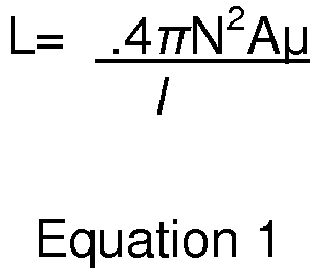
- The
heater conductive wires tether Figures 3A and 3B , with frequency f1, is sent through the coil windings. This signaling current is generally insufficient to detach the implant. Based on the signaling current, the inductive resistance XL (i.e. the electrical resistance due to the inductance within the system) is measured by an electronic circuit such as an ohmmeter. The initial inductance of the system L1 is then calculated according to the formula: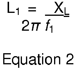
- This initial value of the inductance L1 depends on the magnetic permeability µ1 of the core of the
tether Equation 1, and is saved for reference. When detachment is desired, a higher current and/or a current with a different frequency than the signaling current is applied through the resistive heater coil, causing thetether implant tether heater heater - A second signaling current and frequency f2 is sent through the
heater - Preferably, the
delivery system 100, 300 used according to this example connects to a device that automatically measures inductance at desired times, performs required calculations, and signals to the user when the implant device has detached from the delivery catheter. However, it should be understood that part or all of these steps can be manually performed to achieve the same result. - The inductance between the attached and detached states can also preferably be determined without directly calculating the inductance. For example, the inductive resistance XL can be measured and compared before and after detachment. In another example, the detachment can be determined by measuring and comparing the time constant of the system, which is the time required for the current to reach a predetermined percentage of its nominal value. Since the time constant depends on the inductance, a change in the time constant would similarly indicate a change in inductance.
- Embodiments may also include a feedback algorithm that is used in conjunction with the detachment detection described above. For example, the algorithm automatically increases the detachment voltage or current automatically after the prior attempt fails to detach the implant device. This cycle of measurement, attempted detachment, measurement, and increased detachment voltage/current continues until detachment is detected or a predetermined current or voltage limit is attained. In this respect, a low power detachment could be first attempted, followed automatically by increased power or time until detachment has occurred. Thus, battery life for a mechanism providing the detachment power is increased while the average coil detachment time is greatly reduced.
- Referring now to
Figures 9 and10 , there is shown an embodiment of adelivery system 500 for use with embodiments herein that includes a detachment detection capability. Thedelivery system 500 operates under the principle that electrical current passing through a coil held in an expanded, open gap configuration will encounter more resistance than electrical current passing through a coil in a contracted, closed gap configuration. In the expanded configuration, the electrical current must follow the entire length of the coiled wire. In the contracted configuration, the electrical current can bridge the coils and travel in a longitudinal direction. - The
delivery system 500 is generally similar to the previously described detachment system 300 seen inFigure 4 , including adelivery pusher 301, containing aheater coil 306 that detaches animplant device 302. Thedetachment system 500 similarly utilizes atether 310 to coupled theimplant device 302 to thedelivery pusher 301. - The
heater coil 306 is preferably a resistance-type heater having a plurality ofloops 306A as seen inFigure 10 , that connects to a voltage source through a connector system at the proximal end of thedelivery pusher 301, such as theconnector system 400 described inFigure 6 . - The
delivery system 500 also includes aheater coil expander 502 that serves two functions. First, it expands theheater coil 306 such that theheater coil 306 maintains a friction-fit attachment to the inside of the insulatingcover 309, thereby connecting the two. Second, theheater coil expander 502 expands theheater coil 306 in such a manner that electricity is forced to flow around eachindividual loop 306A of thecoil 306 in order to maximize the resistance of thecoil 306. - Maximizing the coil resistance not only serves to heat the
coil 306 when voltage is passed through, it also sets an initial value (or "normal" value) for the resistance provided by thecoil 306, which can be used to compare a changed resistance state, indicating detachment of theimplant 302. Hence, theheater coil expander 502 must also be capable of undergoing change when subjected to heat. In this regard, theheater coil expander 502 may be made of any suitable sturdy material capable of holding theheater coil 306 in an expanded, biased state while also being capable of melting or being otherwise reduced by the heat of theheater coil 306 in order to yield to the bias of theheater coil 306 to return to an unbiased state. Examples of acceptable materials include, but are not limited to, polymers and monofilament. - The
heater coil expander 502 shown inFigures 9 and10 operates by longitudinally, or radially and longitudinally, expanding aheater coil 306 which is normally a closed gap coil in a relaxed state. In other words, theindividual loops 306A contact each other when theheater coil 306 is not stretched or radially expanded. Preferably, theheater coil expander 502 may have a coiled shape, similar to theheater coil 306 and as seen inFigure 10 . Alternately, the heater coil expander may have a continuous, tubular shape with helical ridges similar to the individual coil shapes of theexpander 502 inFigure 10 . It should be understood that a variety of different expander shapes that expand the loops orcoils 306A of theheater coil 306 from each other. - Preferably the power source (previously described in this embodiment and connected to the connector system 400) also includes a measuring instrument for measuring the resistance of the
heater coil 306. In this respect, the power source (preferably located in a hand-sized unit) includes an indicator that communicates when a change in resistance has occurred and therefore when detachment of the implant has occurred. - An alternative embodiment of the
heater coil expander 512 is shown inFigures 10 and11 . Theheater coil expander 512 operates in conjunction with theheater coil 306 so that the heater loops are in an open gap state (Figure 10 ), and apusher 350, as previously described inFigure 7 , that conducts electricity. Theheater coil 306 is sized to snugly fit around thepusher 350 in a contracted state. Theheater coil expander 512 operates to separate theheater coil 306 from thepusher 350, electrically isolating theheater coil 306 therefrom. As the heat from theheater coil 306 melts or otherwise reduces or degrades theheater coil expander 512, theheater coil 306 resumes a contracted state (i.e., reduced diameter configuration), making electrical, if not physical, contact with the pusher 350 (Figure 11 ). In this respect the individual loops are shortened, significantly reducing the resistance of the circuit and thereby indicating detachment has occurred. - Another alternative embodiment, the
heater coil expander 502 may be sized to expand theheater coil 306 against the conductive reinforcement circumference 312 (shown inFigure 9 ). Hence, when thecoil 306 is in its initial expanded position, the electricallyconductive reinforcement circumference 312 maintains a low initial resistance that is registered by the controller for the circuit (i.e., the measurement device of the power source). - When the
heater coil 306 is energized, the initial resistance is noted and theheater coil expander 306 melts, degrades or otherwise reduces. Theheater coil 306 then contracts, releasing the attachment tube 512 (and the rest of the implant 510) and the heater coil 522a is no longer shorted out by thereinforcement circumference 312. Thus, the circuit experiences a change in resistance as the electrical current must travel through each of the individual loops 524a. This increase in resistance signifies theimplant 302 is detached. -
Figures 13-16 illustrate another preferred embodiment of adelivery system 600. For illustrative purposes, it should be noted that the outer body of thesystem 600 is not shown. Thedelivery system 600 is generally similar to some of the previously described embodiments, in that it includes atether 606 that secures animplantable device 612 to thedelivery system 600 and aheater coil 604 that causes thetether 606 to break, thereby releasing theimplantable device 612. - However, as seen in these Figures, the
heater coil 604 is sized with a diameter that is much smaller than previous embodiments. More specifically, theheater coil 604 preferably has an internal passage that is only slightly larger in diameter than the outer diameter of thetether 606. In other words, the internal diameter of theheater coil 604 is substantially the same as the outer diameter of thetether 604. - According to one embodiment, the internal passage of the
heating coil 604 solely contains thetether 606. According to another embodiment, the diameter of the internal passage may be large enough for only thetether 606 to pass through. In another embodiment, the diameter may be large enough for only the tether and other components, such assupport mandrel 611 orelectrical wires heater coil 604 maintains a close proximity to thetether 606, allowing thetether 606 to pass through once. - Additionally, the
heater coil 604 preferably includes asmaller diameter region 604A which is positioned closer to thetether 606 than the remaining portions of thecoil 604. In this respect, theregion 604A can more efficiently transfer heat to thetether 606 and therefore break the tether with an otherwise lower temperature than without theregion 604A. Providing a lower temperature reduces the risk of damaging the patient's tissue surrounding thesystem 600. In a specific example, theheater coil 604 has an internal diameter of about 0.1778 mm (.007 inch) and an internal diameter of about 0.127 mm (.005 inch) atregion 604A while thetether 606 has an external diameter of about 0.1016 mm (0.004 inch). - As in previously described embodiments, the
heater coil 604 may be composed of a coiled heating element wire. However, it should be understood that other heater configurations are possible, such as a solid, conducting tube or a wire arranged in a non-coiled shape, such as a wave or undulating pattern that forms an overall tubular shape (that may not completely surround the tether 606). - Both ends of the
tether 606 are preferably secured to an outerstructural coil 602 of thedelivery device 600. For example, the ends of thetether 606 can be tied, glued (e.g., with U.V. cured adhesive), welded or clamped. It should be understood that the ends of thetether 606 can be secured at almost any location along the length of thestructural coil 602, as long as those locations allow at least a portion of thetether 606 to pass through theheater coil 604. For example, both ends of thetether 606 can be secured proximal to theheater coil 604. In another example, one end of the tether can be secured proximal toheater coil 604 and another end can be secured distal to theheater coil 604. - As seen in
Figures 13 ,16, and 17 , thetether 606 preferably passes through openings, cells, loops or other structures of theimplantable device 612. For example, thetether 606 may pass through cells of a stent. As seen inFigure 16 , thetether 606 can pass through multiple cells of thedevice 612 and is maintained under tension as seen inFigures 13 and17 . The tension of thetether 606 keeps thedevice 612 in a compressed state (i.e., compressed in diameter) and abutted to the distal end of the system 600 (e.g., the distal end of the outer body member 609). In this respect, when thetether 606 is broken by theheater coil 604, thetether 606 unwraps from thedevice 612 and stays with thedelivery system 600, not thedevice 612. Hence, thetether 606 does not remain in the patient to potentially cause unwanted complications. - As with previously described embodiments, the
delivery system 600 is connectable to a selectively actuated power supply (e.g., via a button on a handle of the delivery device 600).Wires heater coil 604 at a desired time, causing thecoil 604 to heat and thereby break thetether 606. - Preferably, the
heater coil 604 is supported within thedelivery system 600 by a support mandrel 611 (best seen inFigure 15 ) that extends along a length of thesystem 600. Preferably, thesupport mandrel 611 is secured to theheater coil 604 by welding, adhesive or a mechanical interlocking arrangement (not shown). The proximal end of thesupport mandrel 611 is preferably attached to a core wire or delivery pusher (e.g.,pusher 350 described in other embodiments in this specification). - The
outer coil 602 provides support to the delivery system and can be positioned on the inside of a lumen of the delivery system body 609 (seeFigure 17 ). Alternately, thiscoil 602 can be positioned between material layers of the delivery system body 609 (not shown) or otherwise embedded in the material of thedelivery system body 609. - In operation, a distal end of the
delivery system 600 is positioned at a target location within a patient. When the implantable device 612 (e.g., catheter, valve or microcoil) has achieved a desired position, the user provides electric current to the heater coil 604 (e.g., via a button on the delivery device 600). Theheater coil 604, includingsection 604A, increases in temperature, causing thetether 606 to break. Thetether 606, previously under tension, passes through the cells or attachment points of theimplantable device 612 releasing thedevice 612 from thedelivery system 600. Thedelivery system 600 can then be removed from the patient, along with the attachedtether 606. - It should be understood that other tether arrangements are possible. For example,
Figure 18 illustrates the use of threetethers device 612. Preferably, thesetethers tether 606. In the present preferred embodiment, thetethers device 612 atknots 616. However, adhesives, clamps and other attachment arrangements are also possible. While not shown in the Figures, eachtether device 612, similar to the single tether of previously described embodiments and attached to a location in thedelivery system 600. - Although the invention has been described in terms of particular embodiments and applications, one of ordinary skill in the art, in light of this teaching, can generate additional embodiments and modifications without departing from or exceeding the scope of the claimed invention. For example, the heater coil or heater coil expander could be constructed to activate a switch that provides a user indication of detachment in some manner. Additionally, a visual indicator may be associated with the change in resistance to provide easy indication of detachment. Accordingly, it is to be understood that the drawings and descriptions herein are proffered by way of example to facilitate comprehension of the invention and should not be construed to limit the scope thereof.
Claims (12)
- A delivery system for an implant comprising:an implant (612);an elongated member (602) having a distal end and a proximal end;said distal end of said elongated member operable to hold said implant (612);a tether member (606) connectable to said elongated member and to said implant (612);a heating member comprising a resistance-type heater coil (604) that is disposed on said elongated member; said heating member having a hollow passage in which at least a portion of said tether member (606) resides; anda first electrical wire (608) connected at a distal end of said heater coil (604) and a second electrical wire (610) connected at a proximal end of said heater coil (604), wherein said first electrical wire (608) and said second electrical wire (610) supply direct current between said distal end of said heater coil (604) and said proximal end of said heater coil (604);wherein said hollow passage comprises a first region having a first plurality of loops with a first internal diameter and a second region (604A) having a second plurality of loops with a second internal diameter; said tether member (606) being located within said first plurality of loops and said second plurality of loops, and being the only item residing in said hollow passage of said heating member; and wherein said second region is positioned closer to said tether member (606) than said first region, characterised in that said second internal diameter is smaller than said first internal diameter.
- The delivery system of claim 1, wherein said tether (606) has an external diameter of about 0.1016 mm (0.004 inch), said first diameter is about 0.1778 mm (0.007 inch) and said second diameter is about 0.127 mm (0.005 inch).
- The delivery system of claim 1, wherein said heating member is an electrically actuated heater coil (604) that is fixed along a side of said elongated member.
- The delivery system of claim 1, wherein said implant (612) is a stent having a plurality of cells and wherein said tether member (606) is positioned through at least one of said plurality of cells.
- The delivery system of claim 4, wherein said tether member (606) passes through multiple cells of said plurality of cells.
- The delivery system of claim 5, wherein said tether member (606) maintains said stent in a compressed configuration.
- The delivery system of claim 1, wherein
said heating member has an internal diameter that is substantially the same as an outer diameter of said tether member (606); and
wherein said heating member is controllable to generate a temperature increase that causes breakage of said tether member (606). - The delivery system of claim 1, wherein said heating member has a tubular shape.
- The delivery system of claim 1, wherein said tether member (606) comprises at least three tether strands and wherein each of said at least three tether strands are fixed to said implant (612).
- The implant delivery system according to claim 1, wherein
said tether member (606) is being connectable to said implant (612) so as to hold said implant (612) to said elongated member. - The implant delivery system of claim 1, wherein said hollow passage of said heating member is sized to enclose only said tether member (606).
- The implant delivery system of claim 1, wherein an outer surface of said heating member is fixed to said elongated member.
Applications Claiming Priority (2)
| Application Number | Priority Date | Filing Date | Title |
|---|---|---|---|
| US16962909P | 2009-04-15 | 2009-04-15 | |
| PCT/US2010/031256 WO2010121037A1 (en) | 2009-04-15 | 2010-04-15 | Implant delivery system |
Publications (3)
| Publication Number | Publication Date |
|---|---|
| EP2419166A1 EP2419166A1 (en) | 2012-02-22 |
| EP2419166A4 EP2419166A4 (en) | 2015-10-28 |
| EP2419166B1 true EP2419166B1 (en) | 2017-11-22 |
Family
ID=42981558
Family Applications (1)
| Application Number | Title | Priority Date | Filing Date |
|---|---|---|---|
| EP10765189.5A Active EP2419166B1 (en) | 2009-04-15 | 2010-04-15 | Implant delivery system |
Country Status (9)
| Country | Link |
|---|---|
| US (5) | US9717500B2 (en) |
| EP (1) | EP2419166B1 (en) |
| JP (2) | JP5608731B2 (en) |
| KR (1) | KR101719831B1 (en) |
| CN (1) | CN102481436B (en) |
| AU (1) | AU2010236337B2 (en) |
| BR (1) | BRPI1014975A2 (en) |
| CA (1) | CA2758509C (en) |
| WO (1) | WO2010121037A1 (en) |
Families Citing this family (276)
| Publication number | Priority date | Publication date | Assignee | Title |
|---|---|---|---|---|
| US8425549B2 (en) | 2002-07-23 | 2013-04-23 | Reverse Medical Corporation | Systems and methods for removing obstructive matter from body lumens and treating vascular defects |
| US8267985B2 (en) | 2005-05-25 | 2012-09-18 | Tyco Healthcare Group Lp | System and method for delivering and deploying an occluding device within a vessel |
| WO2006127005A1 (en) | 2005-05-25 | 2006-11-30 | Chestnut Medical Technologies, Inc. | System and method for delivering and deploying and occluding device within a vessel |
| AU2006304660B2 (en) | 2005-10-19 | 2013-10-24 | Pulsar Vascular, Inc. | Methods and systems for endovascularly clipping and repairing lumen and tissue defects |
| US8777979B2 (en) | 2006-04-17 | 2014-07-15 | Covidien Lp | System and method for mechanically positioning intravascular implants |
| CN102178553B (en) | 2006-04-17 | 2014-08-13 | 泰科保健集团有限合伙公司 | System and method for mechanically positioning intravascular implants |
| US8585713B2 (en) | 2007-10-17 | 2013-11-19 | Covidien Lp | Expandable tip assembly for thrombus management |
| US11337714B2 (en) | 2007-10-17 | 2022-05-24 | Covidien Lp | Restoring blood flow and clot removal during acute ischemic stroke |
| US10123803B2 (en) | 2007-10-17 | 2018-11-13 | Covidien Lp | Methods of managing neurovascular obstructions |
| US9198687B2 (en) | 2007-10-17 | 2015-12-01 | Covidien Lp | Acute stroke revascularization/recanalization systems processes and products thereby |
| US9220522B2 (en) | 2007-10-17 | 2015-12-29 | Covidien Lp | Embolus removal systems with baskets |
| US8066757B2 (en) | 2007-10-17 | 2011-11-29 | Mindframe, Inc. | Blood flow restoration and thrombus management methods |
| US8926680B2 (en) | 2007-11-12 | 2015-01-06 | Covidien Lp | Aneurysm neck bridging processes with revascularization systems methods and products thereby |
| US8088140B2 (en) | 2008-05-19 | 2012-01-03 | Mindframe, Inc. | Blood flow restorative and embolus removal methods |
| AU2008340276B2 (en) | 2007-12-21 | 2014-08-07 | Microvention, Inc. | System and method for locating detachment zone of a detachable implant |
| US8192480B2 (en) | 2007-12-21 | 2012-06-05 | Microvention, Inc. | System and method of detecting implant detachment |
| RU2506912C2 (en) | 2008-02-22 | 2014-02-20 | Микро Терапьютикс, Инк. | Methods and device for restoring flow |
| EP2271390A4 (en) | 2008-04-11 | 2016-07-20 | Covidien Lp | Monorail neuro-microcatheter for delivery of medical devices to treat stroke, processes and products thereby |
| US9675482B2 (en) | 2008-05-13 | 2017-06-13 | Covidien Lp | Braid implant delivery systems |
| US9402707B2 (en) | 2008-07-22 | 2016-08-02 | Neuravi Limited | Clot capture systems and associated methods |
| ES2879278T3 (en) | 2008-09-05 | 2021-11-22 | Pulsar Vascular Inc | Systems to support or occlude a physiological opening or cavity |
| US9814562B2 (en) | 2009-11-09 | 2017-11-14 | Covidien Lp | Interference-relief type delivery detachment systems |
| US9307980B2 (en) | 2010-01-22 | 2016-04-12 | 4Tech Inc. | Tricuspid valve repair using tension |
| US10058323B2 (en) | 2010-01-22 | 2018-08-28 | 4 Tech Inc. | Tricuspid valve repair using tension |
| US8475525B2 (en) | 2010-01-22 | 2013-07-02 | 4Tech Inc. | Tricuspid valve repair using tension |
| BR112012025969B1 (en) | 2010-04-14 | 2021-01-05 | Microvention, Inc. | implant delivery device |
| ES2683943T3 (en) | 2010-10-22 | 2018-09-28 | Neuravi Limited | Clot capture and removal system |
| US20120203322A1 (en) * | 2011-02-07 | 2012-08-09 | Eells Robert M | Quick release mechanism for medical device deployment |
| US11259824B2 (en) | 2011-03-09 | 2022-03-01 | Neuravi Limited | Clot retrieval device for removing occlusive clot from a blood vessel |
| US12076037B2 (en) | 2011-03-09 | 2024-09-03 | Neuravi Limited | Systems and methods to restore perfusion to a vessel |
| ES3029850T3 (en) | 2011-03-09 | 2025-06-25 | Neuravi Ltd | A clot retrieval device for removing occlusive clot from a blood vessel |
| WO2012127309A1 (en) | 2011-03-21 | 2012-09-27 | Ontorfano Matteo | Disk-based valve apparatus and method for the treatment of valve dysfunction |
| US9005267B2 (en) | 2011-04-29 | 2015-04-14 | Cleveland Clinic Foundation | Rotational alignment wire system for an endovascular delivery system |
| US9381078B2 (en) | 2011-04-29 | 2016-07-05 | The Cleveland Clinic Foundation | Power and/or signal trigger wire for an endovascular delivery system |
| WO2012167156A1 (en) | 2011-06-03 | 2012-12-06 | Pulsar Vascular, Inc. | Aneurysm devices with additional anchoring mechanisms and associated systems and methods |
| US10779855B2 (en) | 2011-08-05 | 2020-09-22 | Route 92 Medical, Inc. | Methods and systems for treatment of acute ischemic stroke |
| EP4529864A3 (en) | 2011-08-05 | 2025-06-04 | Route 92 Medical, Inc. | System for treatment of acute ischemic stroke |
| US8945171B2 (en) | 2011-09-29 | 2015-02-03 | Covidien Lp | Delivery system for implantable devices |
| US8795313B2 (en) | 2011-09-29 | 2014-08-05 | Covidien Lp | Device detachment systems with indicators |
| WO2013049837A1 (en) | 2011-09-30 | 2013-04-04 | Medicalcue, Inc. | Umbilical probe measurement systems |
| ES2809210T3 (en) | 2011-10-05 | 2021-03-03 | Pulsar Vascular Inc | Systems and devices for wrapping an anatomical opening |
| US9579104B2 (en) | 2011-11-30 | 2017-02-28 | Covidien Lp | Positioning and detaching implants |
| US9155540B2 (en) * | 2012-03-30 | 2015-10-13 | DePuy Synthes Products, Inc. | Embolic coil detachment mechanism with heating element and kicker |
| EP2846707A4 (en) | 2012-05-04 | 2016-11-30 | Interventco Llc | Device and method for filling of aneurysm or body cavity |
| WO2013179137A2 (en) | 2012-05-31 | 2013-12-05 | Javelin Medical Ltd. | Systems, methods and devices for embolic protection |
| US8961594B2 (en) | 2012-05-31 | 2015-02-24 | 4Tech Inc. | Heart valve repair system |
| US9155647B2 (en) | 2012-07-18 | 2015-10-13 | Covidien Lp | Methods and apparatus for luminal stenting |
| US8597323B1 (en) * | 2012-11-16 | 2013-12-03 | Sequent Medical, Inc. | Delivery and detachment systems and methods for vascular implants |
| CN105007832B (en) | 2013-01-09 | 2018-01-23 | 4科技有限公司 | Organize ancora equipment |
| US10342546B2 (en) | 2013-01-14 | 2019-07-09 | Microvention, Inc. | Occlusive device |
| EP3991692A3 (en) * | 2013-01-18 | 2022-07-06 | Javelin Medical Ltd. | Monofilament implants and systems for delivery thereof |
| US11399842B2 (en) | 2013-03-13 | 2022-08-02 | Conformal Medical, Inc. | Devices and methods for excluding the left atrial appendage |
| US10603157B2 (en) | 2013-03-13 | 2020-03-31 | DePuy Synthes Products, Inc. | Braid implant delivery and retraction device with distal engagement |
| US10561509B2 (en) | 2013-03-13 | 2020-02-18 | DePuy Synthes Products, Inc. | Braided stent with expansion ring and method of delivery |
| EP2968878B1 (en) | 2013-03-13 | 2020-08-12 | Conformal Medical, Inc. | Devices for excluding the left atrial appendage |
| US9433429B2 (en) | 2013-03-14 | 2016-09-06 | Neuravi Limited | Clot retrieval devices |
| SI2967610T1 (en) | 2013-03-14 | 2019-07-31 | Neuravi Limited | A clot retrieval device for removing occlusive clot from a blood vessel |
| WO2014160055A1 (en) * | 2013-03-14 | 2014-10-02 | R. J. Reynolds Tobacco Company | Atomizer for an aerosol delivery device and related input, aerosol production assembly, cartridge, and method |
| CN105208978B (en) * | 2013-03-14 | 2016-12-07 | 4科技有限公司 | Stand with tether interface |
| TR201901830T4 (en) | 2013-03-14 | 2019-03-21 | Neuravi Ltd | Devices and methods for the removal of acute blockages from blood vessels. |
| WO2014159116A1 (en) | 2013-03-14 | 2014-10-02 | Spiration, Inc. | Valve loader method, system, and apparatus |
| CN110169802B (en) | 2013-03-15 | 2022-07-08 | 柯惠有限合伙公司 | Delivery and detachment mechanism for vascular implants |
| US9561103B2 (en) | 2013-07-17 | 2017-02-07 | Cephea Valve Technologies, Inc. | System and method for cardiac valve repair and replacement |
| US10039643B2 (en) | 2013-10-30 | 2018-08-07 | 4Tech Inc. | Multiple anchoring-point tension system |
| US10052095B2 (en) | 2013-10-30 | 2018-08-21 | 4Tech Inc. | Multiple anchoring-point tension system |
| US9592110B1 (en) | 2013-12-06 | 2017-03-14 | Javelin Medical, Ltd. | Systems and methods for implant delivery |
| US9265512B2 (en) | 2013-12-23 | 2016-02-23 | Silk Road Medical, Inc. | Transcarotid neurovascular catheter |
| US11224437B2 (en) * | 2014-01-14 | 2022-01-18 | Penumbra, Inc. | Soft embolic implant |
| US10285720B2 (en) | 2014-03-11 | 2019-05-14 | Neuravi Limited | Clot retrieval system for removing occlusive clot from a blood vessel |
| US10390943B2 (en) | 2014-03-17 | 2019-08-27 | Evalve, Inc. | Double orifice device for transcatheter mitral valve replacement |
| US11076860B2 (en) | 2014-03-31 | 2021-08-03 | DePuy Synthes Products, Inc. | Aneurysm occlusion device |
| US11154302B2 (en) | 2014-03-31 | 2021-10-26 | DePuy Synthes Products, Inc. | Aneurysm occlusion device |
| US9867622B2 (en) | 2014-04-11 | 2018-01-16 | Microvention, Inc. | Implant delivery system |
| EP3134010B1 (en) | 2014-04-25 | 2020-04-22 | Flow Medtech, LLC | Left atrial appendage occlusion device |
| EP3136986B1 (en) | 2014-04-30 | 2019-04-17 | Cerus Endovascular Limited | Occlusion device |
| WO2015189354A1 (en) | 2014-06-13 | 2015-12-17 | Neuravi Limited | Devices for removal of acute blockages from blood vessels |
| EP3157607B1 (en) | 2014-06-19 | 2019-08-07 | 4Tech Inc. | Cardiac tissue cinching |
| US10265086B2 (en) | 2014-06-30 | 2019-04-23 | Neuravi Limited | System for removing a clot from a blood vessel |
| US9987015B2 (en) | 2014-07-25 | 2018-06-05 | Incumedx, Inc. | Covered embolic coils |
| US9918718B2 (en) | 2014-08-08 | 2018-03-20 | DePuy Synthes Products, Inc. | Embolic coil delivery system with retractable mechanical release mechanism |
| US10206796B2 (en) | 2014-08-27 | 2019-02-19 | DePuy Synthes Products, Inc. | Multi-strand implant with enhanced radiopacity |
| CN104398282B (en) * | 2014-09-15 | 2016-08-24 | 北京泰杰伟业科技有限公司 | Can be used for the coil delivery system that electric heating is freed |
| WO2016044740A1 (en) | 2014-09-19 | 2016-03-24 | Flow Medtech, Inc. | Left atrial appendage occlusion device delivery system |
| US9782178B2 (en) | 2014-09-19 | 2017-10-10 | DePuy Synthes Products, Inc. | Vasculature occlusion device detachment system with tapered corewire and heater activated fiber detachment |
| US11253278B2 (en) | 2014-11-26 | 2022-02-22 | Neuravi Limited | Clot retrieval system for removing occlusive clot from a blood vessel |
| US10617435B2 (en) | 2014-11-26 | 2020-04-14 | Neuravi Limited | Clot retrieval device for removing clot from a blood vessel |
| EP3223723B1 (en) | 2014-11-26 | 2020-01-08 | Neuravi Limited | A clot retrieval device for removing occlusive clot from a blood vessel |
| CN106999178B (en) | 2014-12-02 | 2019-12-24 | 4科技有限公司 | Eccentric Tissue Anchors |
| US9492273B2 (en) | 2014-12-09 | 2016-11-15 | Cephea Valve Technologies, Inc. | Replacement cardiac valves and methods of use and manufacture |
| US11484319B2 (en) | 2015-01-20 | 2022-11-01 | Neurogami Medical, Inc. | Delivery system for micrograft for treating intracranial aneurysms |
| US9962146B2 (en) | 2015-01-20 | 2018-05-08 | Neurogami Medical, Inc. | Micrograft for the treatment of intracranial aneurysms and method for use |
| US10925611B2 (en) | 2015-01-20 | 2021-02-23 | Neurogami Medical, Inc. | Packaging for surgical implant |
| US10857012B2 (en) | 2015-01-20 | 2020-12-08 | Neurogami Medical, Inc. | Vascular implant |
| US10736730B2 (en) | 2015-01-20 | 2020-08-11 | Neurogami Medical, Inc. | Vascular implant |
| US11065019B1 (en) | 2015-02-04 | 2021-07-20 | Route 92 Medical, Inc. | Aspiration catheter systems and methods of use |
| WO2016126974A1 (en) | 2015-02-04 | 2016-08-11 | Route 92 Medical, Inc. | Rapid aspiration thrombectomy system and method |
| US9724507B2 (en) * | 2015-03-13 | 2017-08-08 | Medtronic, Inc. | Interventional medical systems and associated tethering assemblies and methods |
| US9717503B2 (en) * | 2015-05-11 | 2017-08-01 | Covidien Lp | Electrolytic detachment for implant delivery systems |
| WO2016183523A1 (en) | 2015-05-14 | 2016-11-17 | Cephea Valve Technologies, Inc. | Cardiac valve delivery devices and systems |
| WO2016183526A1 (en) | 2015-05-14 | 2016-11-17 | Cephea Valve Technologies, Inc. | Replacement mitral valves |
| WO2017019563A1 (en) | 2015-07-24 | 2017-02-02 | Route 92 Medical, Inc. | Anchoring delivery system and methods |
| CN108348323B (en) | 2015-09-18 | 2021-11-16 | 微仙美国有限公司 | Implant retention, detachment and delivery system |
| US10639456B2 (en) | 2015-09-28 | 2020-05-05 | Microvention, Inc. | Guidewire with torque transmission element |
| US10052108B2 (en) * | 2015-10-30 | 2018-08-21 | Incumedx, Inc. | Devices and methods for delivering an implant to a vascular disorder |
| US11090055B2 (en) | 2015-10-30 | 2021-08-17 | Incumedx Inc. | Devices and methods for delivering an implant to a vascular disorder |
| US10716915B2 (en) | 2015-11-23 | 2020-07-21 | Mivi Neuroscience, Inc. | Catheter systems for applying effective suction in remote vessels and thrombectomy procedures facilitated by catheter systems |
| EP3386402B1 (en) | 2015-12-07 | 2022-02-23 | Cerus Endovascular Limited | Occlusion device |
| US10729447B2 (en) * | 2016-02-10 | 2020-08-04 | Microvention, Inc. | Devices for vascular occlusion |
| CN113350655B (en) | 2016-02-24 | 2024-03-19 | 禾木(中国)生物工程有限公司 | Nerve vascular catheter with enhanced flexibility |
| CN107411859B (en) * | 2016-03-08 | 2019-01-18 | 青岛亿嘉诺日化有限公司 | Tool for implantable intravascular expander |
| EP3426181B1 (en) | 2016-03-11 | 2020-10-21 | Cerus Endovascular Limited | Occlusion device |
| WO2017201316A1 (en) | 2016-05-18 | 2017-11-23 | Microvention, Inc. | Embolic containment |
| US10285710B2 (en) | 2016-06-01 | 2019-05-14 | DePuy Synthes Products, Inc. | Endovascular detachment system with flexible distal end and heater activated detachment |
| US10470773B2 (en) | 2016-06-10 | 2019-11-12 | Terumo Corporation | Vessel occluder |
| WO2017218877A1 (en) * | 2016-06-17 | 2017-12-21 | Cephea Valve Technologies, Inc. | Cardiac valve delivery devices and systems |
| US10828037B2 (en) | 2016-06-27 | 2020-11-10 | Covidien Lp | Electrolytic detachment with fluid electrical connection |
| US10828039B2 (en) | 2016-06-27 | 2020-11-10 | Covidien Lp | Electrolytic detachment for implantable devices |
| US11051822B2 (en) | 2016-06-28 | 2021-07-06 | Covidien Lp | Implant detachment with thermal activation |
| US10420563B2 (en) * | 2016-07-08 | 2019-09-24 | Neurogami Medical, Inc. | Delivery system insertable through body lumen |
| AU2017312421A1 (en) | 2016-08-17 | 2019-03-07 | Neuravi Limited | A clot retrieval system for removing occlusive clot from a blood vessel |
| US10076428B2 (en) | 2016-08-25 | 2018-09-18 | DePuy Synthes Products, Inc. | Expansion ring for a braided stent |
| CA3035706A1 (en) | 2016-09-06 | 2018-03-15 | Neuravi Limited | A clot retrieval device for removing occlusive clot from a blood vessel |
| US10292851B2 (en) | 2016-09-30 | 2019-05-21 | DePuy Synthes Products, Inc. | Self-expanding device delivery apparatus with dual function bump |
| ES2967415T3 (en) | 2016-10-21 | 2024-04-30 | Javelin Medical Ltd | Embolic protection devices |
| US10517708B2 (en) | 2016-10-26 | 2019-12-31 | DePuy Synthes Products, Inc. | Multi-basket clot capturing device |
| WO2018081466A2 (en) | 2016-10-27 | 2018-05-03 | Conformal Medical, Inc. | Devices and methods for excluding the left atrial appendage |
| US11426172B2 (en) | 2016-10-27 | 2022-08-30 | Conformal Medical, Inc. | Devices and methods for excluding the left atrial appendage |
| US10363138B2 (en) | 2016-11-09 | 2019-07-30 | Evalve, Inc. | Devices for adjusting the curvature of cardiac valve structures |
| US10426616B2 (en) | 2016-11-17 | 2019-10-01 | Evalve, Inc. | Cardiac implant delivery system |
| EP3565511B1 (en) | 2017-01-06 | 2023-10-18 | Incept, LLC | Thromboresistant coatings for aneurysm treatment devices |
| EP3568186B1 (en) | 2017-01-10 | 2022-09-14 | Route 92 Medical, Inc. | Aspiration catheter systems |
| US10905853B2 (en) | 2017-01-17 | 2021-02-02 | DePuy Synthes Products, Inc. | System and method for delivering a catheter |
| WO2018136745A1 (en) | 2017-01-20 | 2018-07-26 | Route 92 Medical, Inc. | Single operator intracranial medical device delivery systems and methods of use |
| CN110621260B (en) | 2017-01-23 | 2022-11-25 | 科菲瓣膜技术有限公司 | Replacement mitral valve |
| AU2018203053B2 (en) | 2017-01-23 | 2020-03-05 | Cephea Valve Technologies, Inc. | Replacement mitral valves |
| US10881497B2 (en) | 2017-01-26 | 2021-01-05 | DePuy Synthes Products, Inc. | Composite vascular flow diverter |
| EP3585275A1 (en) | 2017-02-23 | 2020-01-01 | DePuy Synthes Products, Inc. | Aneurysm device and delivery system |
| ES2971315T3 (en) | 2017-08-21 | 2024-06-04 | Cerus Endovascular Ltd | Occlusion device |
| US10806462B2 (en) | 2017-12-21 | 2020-10-20 | DePuy Synthes Products, Inc. | Implantable medical device detachment system with split tube and cylindrical coupling |
| US10751065B2 (en) | 2017-12-22 | 2020-08-25 | DePuy Synthes Products, Inc. | Aneurysm device and delivery system |
| US10905430B2 (en) | 2018-01-24 | 2021-02-02 | DePuy Synthes Products, Inc. | Aneurysm device and delivery system |
| US10786259B2 (en) | 2018-03-30 | 2020-09-29 | DePuy Synthes Products, Inc. | Split balloon assist device and method for using the same |
| US10918390B2 (en) | 2018-03-30 | 2021-02-16 | DePuy Synthes Products, Inc. | Helical balloon assist device and method for using the same |
| DE102018109580A1 (en) * | 2018-04-20 | 2019-10-24 | Phenox Gmbh | Device for introducing implants |
| US10806461B2 (en) | 2018-04-27 | 2020-10-20 | DePuy Synthes Products, Inc. | Implantable medical device detachment system with split tube |
| US11395665B2 (en) | 2018-05-01 | 2022-07-26 | Incept, Llc | Devices and methods for removing obstructive material, from an intravascular site |
| AU2019262972B2 (en) | 2018-05-01 | 2025-02-27 | Incept, Llc | Devices and methods for removing obstructive material from an intravascular site |
| EP3793660B1 (en) | 2018-05-17 | 2024-11-13 | Route 92 Medical, Inc. | Aspiration catheter systems |
| US11596412B2 (en) | 2018-05-25 | 2023-03-07 | DePuy Synthes Products, Inc. | Aneurysm device and delivery system |
| US11058430B2 (en) | 2018-05-25 | 2021-07-13 | DePuy Synthes Products, Inc. | Aneurysm device and delivery system |
| US10939915B2 (en) | 2018-05-31 | 2021-03-09 | DePuy Synthes Products, Inc. | Aneurysm device and delivery system |
| US10667833B2 (en) | 2018-06-08 | 2020-06-02 | Neuravi Limited | Guidewire with an atraumatic clot-circumventing configured distal end for use in an endovascular medical system |
| US10898216B2 (en) | 2018-06-13 | 2021-01-26 | DePuy Synthes Products, Inc. | Vasculature obstruction capture device |
| US11471582B2 (en) | 2018-07-06 | 2022-10-18 | Incept, Llc | Vacuum transfer tool for extendable catheter |
| US11517335B2 (en) | 2018-07-06 | 2022-12-06 | Incept, Llc | Sealed neurovascular extendable catheter |
| AU2019204522A1 (en) | 2018-07-30 | 2020-02-13 | DePuy Synthes Products, Inc. | Systems and methods of manufacturing and using an expansion ring |
| US10905431B2 (en) | 2018-08-03 | 2021-02-02 | DePuy Synthes Products, Inc. | Spiral delivery system for embolic braid |
| US10456280B1 (en) | 2018-08-06 | 2019-10-29 | DePuy Synthes Products, Inc. | Systems and methods of using a braided implant |
| US10278848B1 (en) | 2018-08-06 | 2019-05-07 | DePuy Synthes Products, Inc. | Stent delivery with expansion assisting delivery wire |
| US10813780B2 (en) | 2018-08-08 | 2020-10-27 | DePuy Synthes Products, Inc. | Intraluminal implant delivery system and method |
| US11051825B2 (en) | 2018-08-08 | 2021-07-06 | DePuy Synthes Products, Inc. | Delivery system for embolic braid |
| US10842498B2 (en) | 2018-09-13 | 2020-11-24 | Neuravi Limited | Systems and methods of restoring perfusion to a vessel |
| BR102019019522A2 (en) | 2018-09-20 | 2020-04-07 | Depuy Synthes Products Inc | stent with conformed wires |
| US11123077B2 (en) | 2018-09-25 | 2021-09-21 | DePuy Synthes Products, Inc. | Intrasaccular device positioning and deployment system |
| US11406416B2 (en) | 2018-10-02 | 2022-08-09 | Neuravi Limited | Joint assembly for vasculature obstruction capture device |
| US11253287B2 (en) | 2018-10-04 | 2022-02-22 | Neuravi Limited | Retrograde blood flow occlusion flushing device |
| US11076861B2 (en) | 2018-10-12 | 2021-08-03 | DePuy Synthes Products, Inc. | Folded aneurysm treatment device and delivery method |
| US12114863B2 (en) | 2018-12-05 | 2024-10-15 | Microvention, Inc. | Implant delivery system |
| US11406392B2 (en) | 2018-12-12 | 2022-08-09 | DePuy Synthes Products, Inc. | Aneurysm occluding device for use with coagulating agents |
| US11147562B2 (en) | 2018-12-12 | 2021-10-19 | DePuy Synthes Products, Inc. | Systems and methods for embolic implant detachment |
| US11272939B2 (en) | 2018-12-18 | 2022-03-15 | DePuy Synthes Products, Inc. | Intrasaccular flow diverter for treating cerebral aneurysms |
| US11039944B2 (en) | 2018-12-27 | 2021-06-22 | DePuy Synthes Products, Inc. | Braided stent system with one or more expansion rings |
| US11134953B2 (en) | 2019-02-06 | 2021-10-05 | DePuy Synthes Products, Inc. | Adhesive cover occluding device for aneurysm treatment |
| US11273285B2 (en) | 2019-02-07 | 2022-03-15 | DePuy Synthes Products, Inc. | Ancillary device for detaching implants |
| US12268394B2 (en) | 2019-02-08 | 2025-04-08 | Conformal Medical, Inc. | Devices and methods for excluding the left atrial appendage |
| US12144508B2 (en) | 2019-02-08 | 2024-11-19 | Conformal Medical, Inc. | Devices and methods for excluding the left atrial appendage |
| EP4000540B1 (en) | 2019-03-04 | 2024-02-14 | Neuravi Limited | Actuated clot retrieval catheter |
| US11382633B2 (en) | 2019-03-06 | 2022-07-12 | DePuy Synthes Products, Inc. | Strut flow diverter for cerebral aneurysms and methods for preventing strut entanglement |
| US11337706B2 (en) | 2019-03-27 | 2022-05-24 | DePuy Synthes Products, Inc. | Aneurysm treatment device |
| US11185334B2 (en) | 2019-03-28 | 2021-11-30 | DePuy Synthes Products, Inc. | Single lumen reduced profile occlusion balloon catheter |
| US11766539B2 (en) | 2019-03-29 | 2023-09-26 | Incept, Llc | Enhanced flexibility neurovascular catheter |
| US11051928B2 (en) | 2019-04-11 | 2021-07-06 | Neuravi Limited | Floating carotid filter |
| US11571553B2 (en) | 2019-05-09 | 2023-02-07 | Neuravi Limited | Balloon guide catheter with thermally expandable material |
| US11957855B2 (en) | 2019-05-09 | 2024-04-16 | Neuravi Limited | Balloon guide catheter with positive venting of residual air |
| US11607531B2 (en) | 2019-05-09 | 2023-03-21 | Neuravi Limited | Balloon catheter with venting of residual air in a proximal direction |
| US11931522B2 (en) | 2019-05-09 | 2024-03-19 | Neuravi Limited | Inflation lumen kink protection and balloon profile |
| USD959659S1 (en) | 2019-05-10 | 2022-08-02 | DePuy Synthes Products, Inc. | Implant release handle |
| US11497504B2 (en) | 2019-05-21 | 2022-11-15 | DePuy Synthes Products, Inc. | Aneurysm treatment with pushable implanted braid |
| US10653425B1 (en) | 2019-05-21 | 2020-05-19 | DePuy Synthes Products, Inc. | Layered braided aneurysm treatment device |
| US11413046B2 (en) | 2019-05-21 | 2022-08-16 | DePuy Synthes Products, Inc. | Layered braided aneurysm treatment device |
| US11607226B2 (en) | 2019-05-21 | 2023-03-21 | DePuy Synthes Products, Inc. | Layered braided aneurysm treatment device with corrugations |
| US12446886B2 (en) | 2019-05-21 | 2025-10-21 | DePuy Synthes Products, Inc. | Semispherical braided aneurysm treatment system and method |
| US11602350B2 (en) | 2019-12-05 | 2023-03-14 | DePuy Synthes Products, Inc. | Intrasaccular inverting braid with highly flexible fill material |
| US11672542B2 (en) | 2019-05-21 | 2023-06-13 | DePuy Synthes Products, Inc. | Aneurysm treatment with pushable ball segment |
| US11278292B2 (en) | 2019-05-21 | 2022-03-22 | DePuy Synthes Products, Inc. | Inverting braided aneurysm treatment system and method |
| US11109939B2 (en) | 2019-06-14 | 2021-09-07 | DePuy Synthes Products, Inc. | Intravascular devices with radiopaque body markers |
| US11406403B2 (en) | 2019-06-14 | 2022-08-09 | Neuravi Limited | Visibility of mechanical thrombectomy device during diagnostic imaging |
| US11253265B2 (en) | 2019-06-18 | 2022-02-22 | DePuy Synthes Products, Inc. | Pull wire detachment for intravascular devices |
| US11207494B2 (en) | 2019-07-03 | 2021-12-28 | DePuy Synthes Products, Inc. | Medical device delivery member with flexible stretch resistant distal portion |
| US11426174B2 (en) | 2019-10-03 | 2022-08-30 | DePuy Synthes Products, Inc. | Medical device delivery member with flexible stretch resistant mechanical release |
| US11266427B2 (en) | 2019-07-10 | 2022-03-08 | Neuravi Limited | Self-expanding intravascular medical device |
| US11266426B2 (en) | 2019-07-10 | 2022-03-08 | DePuy Synthes Products, Inc. | Streamlined treatment of clot removal, angioplasty and prevention of restenosis using a single integrated intravascular device |
| US11395675B2 (en) | 2019-07-11 | 2022-07-26 | DePuy Synthes Products, Inc. | Clot retriever cleaning for reinsertion |
| CN114401700B (en) * | 2019-07-16 | 2025-12-12 | 微仙美国有限公司 | Medical devices with enhanced shape features |
| EP3788958A1 (en) | 2019-09-09 | 2021-03-10 | Heraeus Deutschland GmbH & Co KG | Electrical contact between electrically conducting polymer coated wires and electrically conducting substrates using wire bonding |
| ES2987037T3 (en) | 2019-09-11 | 2024-11-13 | Neuravi Ltd | Expandable buccal catheter |
| US11439403B2 (en) | 2019-09-17 | 2022-09-13 | DePuy Synthes Products, Inc. | Embolic coil proximal connecting element and stretch resistant fiber |
| US12376859B2 (en) | 2019-09-17 | 2025-08-05 | DePuy Synthes Products, Inc. | Embolic coil proximal connecting element and stretch resistant fiber |
| CN113347916B (en) | 2019-10-15 | 2025-04-25 | 因普瑞缇夫护理公司 | Systems and methods for multivariate stroke detection |
| US11712231B2 (en) | 2019-10-29 | 2023-08-01 | Neuravi Limited | Proximal locking assembly design for dual stent mechanical thrombectomy device |
| US20210128183A1 (en) | 2019-10-31 | 2021-05-06 | Neuravi Limited | Thrombectomy and stenting system |
| US11376013B2 (en) | 2019-11-18 | 2022-07-05 | DePuy Synthes Products, Inc. | Implant delivery system with braid cup formation |
| US11628282B2 (en) | 2019-11-25 | 2023-04-18 | Neuravi Limited | No preparation balloon guide catheter |
| US11779364B2 (en) | 2019-11-27 | 2023-10-10 | Neuravi Limited | Actuated expandable mouth thrombectomy catheter |
| US11839725B2 (en) | 2019-11-27 | 2023-12-12 | Neuravi Limited | Clot retrieval device with outer sheath and inner catheter |
| US12539130B2 (en) | 2019-11-27 | 2026-02-03 | Neuravi Limited | Aspiration catheter, systems, and methods thereof |
| US11517340B2 (en) | 2019-12-03 | 2022-12-06 | Neuravi Limited | Stentriever devices for removing an occlusive clot from a vessel and methods thereof |
| WO2021127004A1 (en) | 2019-12-18 | 2021-06-24 | Imperative Care, Inc. | Methods and systems for treating venous thromboembolic disease |
| US20210315598A1 (en) | 2019-12-18 | 2021-10-14 | Imperative Care, Inc. | Methods of placing large bore aspiration catheters |
| US11633272B2 (en) | 2019-12-18 | 2023-04-25 | Imperative Care, Inc. | Manually rotatable thrombus engagement tool |
| US11457926B2 (en) | 2019-12-18 | 2022-10-04 | DePuy Synthes Products, Inc. | Implant having an intrasaccular section and intravascular section |
| US11457922B2 (en) | 2020-01-22 | 2022-10-04 | DePuy Synthes Products, Inc. | Medical device delivery member with flexible stretch resistant distal portion |
| US11992241B2 (en) | 2020-01-31 | 2024-05-28 | DePuy Synthes Products, Inc. | System to assist delivery of a mechanical intravascular treatment device |
| US11957354B2 (en) | 2020-02-10 | 2024-04-16 | DePuy Synthes Products, Inc. | Aneurysm implant support device |
| US11432822B2 (en) | 2020-02-14 | 2022-09-06 | DePuy Synthes Products, Inc. | Intravascular implant deployment system |
| US11406404B2 (en) | 2020-02-20 | 2022-08-09 | Cerus Endovascular Limited | Clot removal distal protection methods |
| US11944327B2 (en) | 2020-03-05 | 2024-04-02 | Neuravi Limited | Expandable mouth aspirating clot retrieval catheter |
| US11633198B2 (en) | 2020-03-05 | 2023-04-25 | Neuravi Limited | Catheter proximal joint |
| CA3171899A1 (en) | 2020-03-10 | 2021-09-16 | Imperative Care, Inc. | Enhanced flexibility neurovascular catheter |
| US11883043B2 (en) | 2020-03-31 | 2024-01-30 | DePuy Synthes Products, Inc. | Catheter funnel extension |
| US11759217B2 (en) | 2020-04-07 | 2023-09-19 | Neuravi Limited | Catheter tubular support |
| US11717308B2 (en) | 2020-04-17 | 2023-08-08 | Neuravi Limited | Clot retrieval device for removing heterogeneous clots from a blood vessel |
| US11871946B2 (en) | 2020-04-17 | 2024-01-16 | Neuravi Limited | Clot retrieval device for removing clot from a blood vessel |
| US11730501B2 (en) | 2020-04-17 | 2023-08-22 | Neuravi Limited | Floating clot retrieval device for removing clots from a blood vessel |
| US11523831B2 (en) | 2020-04-30 | 2022-12-13 | DePuy Synthes Products, Inc. | Intrasaccular flow diverter |
| US11737771B2 (en) | 2020-06-18 | 2023-08-29 | Neuravi Limited | Dual channel thrombectomy device |
| US11937836B2 (en) | 2020-06-22 | 2024-03-26 | Neuravi Limited | Clot retrieval system with expandable clot engaging framework |
| US11395669B2 (en) | 2020-06-23 | 2022-07-26 | Neuravi Limited | Clot retrieval device with flexible collapsible frame |
| US11439418B2 (en) | 2020-06-23 | 2022-09-13 | Neuravi Limited | Clot retrieval device for removing clot from a blood vessel |
| US11951026B2 (en) | 2020-06-30 | 2024-04-09 | DePuy Synthes Products, Inc. | Implantable medical device detachment system with flexible braid section |
| US20220031341A1 (en) | 2020-07-29 | 2022-02-03 | Neuravi Limited | Adhesive-Free Bonded Balloon for a Balloon Guide Catheter With Minimal Outer Profile |
| US12447319B2 (en) | 2020-07-29 | 2025-10-21 | Neuravi Limited | Enhanced balloon bonding for balloon guide catheters while minimizing outer profiles |
| US11207497B1 (en) | 2020-08-11 | 2021-12-28 | Imperative Care, Inc. | Catheter with enhanced tensile strength |
| US11864781B2 (en) | 2020-09-23 | 2024-01-09 | Neuravi Limited | Rotating frame thrombectomy device |
| EP4225167A4 (en) | 2020-10-09 | 2024-10-09 | Route 92 Medical, Inc. | Aspiration catheter systems and methods of use |
| US12440646B2 (en) | 2020-11-06 | 2025-10-14 | DePuy Synthes Products, Inc. | Catheter braid wire with variable cross-section shape |
| US11786698B2 (en) | 2020-12-08 | 2023-10-17 | DePuy Synthes Products, Inc. | Catheter with textured surface |
| US11826520B2 (en) | 2020-12-08 | 2023-11-28 | DePuy Synthes Products, Inc. | Catheter designs for enhanced column strength |
| US11937837B2 (en) | 2020-12-29 | 2024-03-26 | Neuravi Limited | Fibrin rich / soft clot mechanical thrombectomy device |
| US12029442B2 (en) | 2021-01-14 | 2024-07-09 | Neuravi Limited | Systems and methods for a dual elongated member clot retrieval apparatus |
| US11872354B2 (en) | 2021-02-24 | 2024-01-16 | Neuravi Limited | Flexible catheter shaft frame with seam |
| US12064130B2 (en) | 2021-03-18 | 2024-08-20 | Neuravi Limited | Vascular obstruction retrieval device having sliding cages pinch mechanism |
| EP4308216A4 (en) * | 2021-03-19 | 2025-01-01 | Microvention, Inc. | Recoverable electro thermal detachment systems |
| US11974764B2 (en) | 2021-06-04 | 2024-05-07 | Neuravi Limited | Self-orienting rotating stentriever pinching cells |
| US20240293127A1 (en) | 2021-07-07 | 2024-09-05 | Microvention, Inc. | Stretch resistant embolic coil |
| US11998213B2 (en) | 2021-07-14 | 2024-06-04 | DePuy Synthes Products, Inc. | Implant delivery with modified detachment feature and pull wire engagement |
| US20230052862A1 (en) | 2021-08-12 | 2023-02-16 | Imperative Care, Inc. | Sterile packaging assembly for robotic interventional device |
| US12369920B2 (en) | 2021-09-22 | 2025-07-29 | DePuy Synthes Products, Inc. | Introducer sheath having an intentional friction zone to hold in position a delivery system suitable for implantable intravascular devices |
| US11937839B2 (en) | 2021-09-28 | 2024-03-26 | Neuravi Limited | Catheter with electrically actuated expandable mouth |
| USD1077996S1 (en) | 2021-10-18 | 2025-06-03 | Imperative Care, Inc. | Inline fluid filter |
| US12011186B2 (en) | 2021-10-28 | 2024-06-18 | Neuravi Limited | Bevel tip expandable mouth catheter with reinforcing ring |
| US11751881B2 (en) | 2021-11-26 | 2023-09-12 | DePuy Synthes Products, Inc. | Securement wire withstanding forces during deployment of implantable intravascular treatment device using a delivery and detachment system |
| US11937824B2 (en) | 2021-12-30 | 2024-03-26 | DePuy Synthes Products, Inc. | Implant detachment systems with a modified pull wire |
| US11844490B2 (en) | 2021-12-30 | 2023-12-19 | DePuy Synthes Products, Inc. | Suture linkage for inhibiting premature embolic implant deployment |
| US12508032B2 (en) * | 2021-12-31 | 2025-12-30 | DePuy Synthes Products, Inc. | Medical device delivery systems with twisting loop wires |
| US12220131B2 (en) | 2022-01-06 | 2025-02-11 | DePuy Synthes Products, Inc. | Delivery and detachment system imposing a friction force on a securement wire to minimize movement of an implantable intravascular device |
| US12011171B2 (en) | 2022-01-06 | 2024-06-18 | DePuy Synthes Products, Inc. | Systems and methods for inhibiting premature embolic implant deployment |
| US11937825B2 (en) | 2022-03-02 | 2024-03-26 | DePuy Synthes Products, Inc. | Hook wire for preventing premature embolic implant detachment |
| US12471924B2 (en) | 2022-03-02 | 2025-11-18 | DePuy Synthes Products, Inc. | Flexible feature for embolic implant deployment |
| US12137915B2 (en) | 2022-03-03 | 2024-11-12 | DePuy Synthes Products, Inc. | Elongating wires for inhibiting premature implant detachment |
| US11937826B2 (en) | 2022-03-14 | 2024-03-26 | DePuy Synthes Products, Inc. | Proximal link wire for preventing premature implant detachment |
| US12402886B2 (en) | 2022-06-23 | 2025-09-02 | DePuy Synthes Products, Inc. | Detachment indicator for implant deployment |
| US12458380B2 (en) | 2022-07-29 | 2025-11-04 | Neuravi Limited | Mechanical thrombectomy device for capture and removal of occlusions |
| US12446888B2 (en) | 2022-08-26 | 2025-10-21 | Depuy Synthes Products, Inc | Twister implant detachment mechanism |
| US12396730B2 (en) | 2022-09-28 | 2025-08-26 | DePuy Synthes Products, Inc. | Braided implant with detachment mechanism |
| WO2025260076A1 (en) * | 2024-06-14 | 2025-12-18 | Cobra Neurovascular LLC | Vascular stent with adjustable radial strength |
Family Cites Families (44)
| Publication number | Priority date | Publication date | Assignee | Title |
|---|---|---|---|---|
| US4346712A (en) | 1979-04-06 | 1982-08-31 | Kuraray Company, Ltd. | Releasable balloon catheter |
| US5122136A (en) * | 1990-03-13 | 1992-06-16 | The Regents Of The University Of California | Endovascular electrolytically detachable guidewire tip for the electroformation of thrombus in arteries, veins, aneurysms, vascular malformations and arteriovenous fistulas |
| US5108407A (en) * | 1990-06-08 | 1992-04-28 | Rush-Presbyterian St. Luke's Medical Center | Method and apparatus for placement of an embolic coil |
| WO1992020290A1 (en) * | 1991-05-17 | 1992-11-26 | Innerdyne Medical, Inc. | Method and device for thermal ablation |
| FR2699809B1 (en) * | 1992-12-28 | 1995-02-17 | Celsa Lg | Device which can selectively constitute a temporary blood filter. |
| CA2159734A1 (en) * | 1993-03-30 | 1994-10-13 | Rafael Beyar | Temporary stent system |
| US5578074A (en) * | 1994-12-22 | 1996-11-26 | Target Therapeutics, Inc. | Implant delivery method and assembly |
| US5582619A (en) * | 1995-06-30 | 1996-12-10 | Target Therapeutics, Inc. | Stretch resistant vaso-occlusive coils |
| US6013084A (en) * | 1995-06-30 | 2000-01-11 | Target Therapeutics, Inc. | Stretch resistant vaso-occlusive coils (II) |
| US5749921A (en) | 1996-02-20 | 1998-05-12 | Medtronic, Inc. | Apparatus and methods for compression of endoluminal prostheses |
| US5925061A (en) * | 1997-01-13 | 1999-07-20 | Gore Enterprise Holdings, Inc. | Low profile vascular stent |
| US5984929A (en) * | 1997-08-29 | 1999-11-16 | Target Therapeutics, Inc. | Fast detaching electronically isolated implant |
| US6478773B1 (en) * | 1998-12-21 | 2002-11-12 | Micrus Corporation | Apparatus for deployment of micro-coil using a catheter |
| US6500149B2 (en) * | 1998-08-31 | 2002-12-31 | Deepak Gandhi | Apparatus for deployment of micro-coil using a catheter |
| US6277126B1 (en) * | 1998-10-05 | 2001-08-21 | Cordis Neurovascular Inc. | Heated vascular occlusion coil development system |
| ATE239424T1 (en) * | 1998-12-16 | 2003-05-15 | Arthesys | CATHETER SYSTEM FOR HYDRAULIC RELEASE OF EMBOLIZATION CIRCUITS |
| US6830581B2 (en) * | 1999-02-09 | 2004-12-14 | Innercool Therspies, Inc. | Method and device for patient temperature control employing optimized rewarming |
| US6602261B2 (en) * | 1999-10-04 | 2003-08-05 | Microvention, Inc. | Filamentous embolic device with expansile elements |
| US7740637B2 (en) * | 2000-02-09 | 2010-06-22 | Micrus Endovascular Corporation | Apparatus and method for deployment of a therapeutic device using a catheter |
| US6632241B1 (en) * | 2000-03-22 | 2003-10-14 | Endovascular Technologies, Inc. | Self-expanding, pseudo-braided intravascular device |
| US6494884B2 (en) * | 2001-02-09 | 2002-12-17 | Concentric Medical, Inc. | Methods and devices for delivering occlusion elements |
| US6716238B2 (en) * | 2001-05-10 | 2004-04-06 | Scimed Life Systems, Inc. | Stent with detachable tethers and method of using same |
| EP2319430B1 (en) * | 2001-05-29 | 2013-11-13 | Microvention, Inc. | Vascular embolization device and method of manufacture |
| US7485122B2 (en) * | 2002-06-27 | 2009-02-03 | Boston Scientific Scimed, Inc. | Integrated anchor coil in stretch-resistant vaso-occlusive coils |
| US7608058B2 (en) * | 2002-07-23 | 2009-10-27 | Micrus Corporation | Stretch resistant therapeutic device |
| US20050171572A1 (en) * | 2002-07-31 | 2005-08-04 | Microvention, Inc. | Multi-layer coaxial vaso-occlusive device |
| JP4566988B2 (en) * | 2003-04-02 | 2010-10-20 | ボストン サイエンティフィック リミテッド | Separable and recoverable stent assembly |
| US20080109057A1 (en) * | 2003-12-10 | 2008-05-08 | Calabria Marie F | Multiple point detacher system |
| CN104523313B (en) * | 2004-08-25 | 2018-05-18 | 微仙美国有限公司 | implant device delivery system |
| CN101048107A (en) * | 2004-10-29 | 2007-10-03 | 株式会社钟化 | Medical wire |
| US20060116714A1 (en) | 2004-11-26 | 2006-06-01 | Ivan Sepetka | Coupling and release devices and methods for their assembly and use |
| US7608089B2 (en) * | 2004-12-22 | 2009-10-27 | Boston Scientific Scimed, Inc. | Vaso-occlusive device having pivotable coupling |
| EP1884208B1 (en) * | 2005-05-24 | 2015-02-25 | Kaneka Corporation | Medical wire |
| US7708754B2 (en) | 2005-06-02 | 2010-05-04 | Codman & Shurtleff, Pc | Stretch resistant embolic coil delivery system with mechanical release mechanism |
| JP4627687B2 (en) * | 2005-06-20 | 2011-02-09 | Junken Medical株式会社 | Stent insertion device |
| US7591833B2 (en) * | 2005-06-30 | 2009-09-22 | Codman & Shurtleff, Inc. | Laser-based vascular occlusion device detachment system |
| US20070100414A1 (en) * | 2005-11-02 | 2007-05-03 | Cardiomind, Inc. | Indirect-release electrolytic implant delivery systems |
| US8414632B2 (en) * | 2006-03-06 | 2013-04-09 | Boston Scientific Scimed, Inc. | Adjustable catheter tip |
| US7771451B2 (en) * | 2006-04-05 | 2010-08-10 | Boston Scientific Scimed, Inc. | Method and apparatus for the deployment of vaso-occlusive coils |
| EP2705874B1 (en) * | 2007-03-19 | 2016-09-28 | Boston Scientific Neuromodulation Corporation | MRI and RF compatible leads |
| JP5389788B2 (en) * | 2007-05-18 | 2014-01-15 | ストライカー コーポレイション | Medical implant separation system |
| EP2175782B1 (en) * | 2007-07-27 | 2016-09-07 | MicroVention, Inc. | Detachable coil incorporating stretch resistance |
| US8192480B2 (en) * | 2007-12-21 | 2012-06-05 | Microvention, Inc. | System and method of detecting implant detachment |
| US20090177261A1 (en) * | 2008-01-04 | 2009-07-09 | Boston Scientific Scimed, Inc. | Detachment mechanisms for implantable devices |
-
2010
- 2010-04-15 EP EP10765189.5A patent/EP2419166B1/en active Active
- 2010-04-15 AU AU2010236337A patent/AU2010236337B2/en not_active Ceased
- 2010-04-15 CN CN201080026639.7A patent/CN102481436B/en active Active
- 2010-04-15 JP JP2012506228A patent/JP5608731B2/en active Active
- 2010-04-15 KR KR1020117026573A patent/KR101719831B1/en active Active
- 2010-04-15 CA CA2758509A patent/CA2758509C/en active Active
- 2010-04-15 US US12/761,113 patent/US9717500B2/en active Active
- 2010-04-15 BR BRPI1014975A patent/BRPI1014975A2/en not_active Application Discontinuation
- 2010-04-15 WO PCT/US2010/031256 patent/WO2010121037A1/en not_active Ceased
-
2014
- 2014-09-01 JP JP2014176764A patent/JP2015027475A/en active Pending
-
2017
- 2017-06-23 US US15/631,833 patent/US20170281192A1/en not_active Abandoned
-
2018
- 2018-10-05 US US16/153,267 patent/US20190038294A1/en not_active Abandoned
-
2021
- 2021-02-16 US US17/177,020 patent/US11857196B2/en active Active
-
2023
- 2023-12-13 US US18/539,170 patent/US12295583B2/en active Active
Non-Patent Citations (1)
| Title |
|---|
| None * |
Also Published As
| Publication number | Publication date |
|---|---|
| JP2012523931A (en) | 2012-10-11 |
| CA2758509C (en) | 2018-02-20 |
| KR101719831B1 (en) | 2017-03-24 |
| US12295583B2 (en) | 2025-05-13 |
| WO2010121037A1 (en) | 2010-10-21 |
| US20190038294A1 (en) | 2019-02-07 |
| BRPI1014975A2 (en) | 2016-04-26 |
| US20170281192A1 (en) | 2017-10-05 |
| EP2419166A4 (en) | 2015-10-28 |
| CA2758509A1 (en) | 2010-10-21 |
| US20240108352A1 (en) | 2024-04-04 |
| JP5608731B2 (en) | 2014-10-15 |
| CN102481436A (en) | 2012-05-30 |
| US20210161539A1 (en) | 2021-06-03 |
| US20100268204A1 (en) | 2010-10-21 |
| US11857196B2 (en) | 2024-01-02 |
| AU2010236337B2 (en) | 2015-01-29 |
| EP2419166A1 (en) | 2012-02-22 |
| US9717500B2 (en) | 2017-08-01 |
| JP2015027475A (en) | 2015-02-12 |
| CN102481436B (en) | 2016-06-01 |
| AU2010236337A1 (en) | 2011-11-17 |
| KR20120027224A (en) | 2012-03-21 |
Similar Documents
| Publication | Publication Date | Title |
|---|---|---|
| US12295583B2 (en) | Implant delivery system | |
| US12114864B2 (en) | Implant delivery device | |
| US11918230B2 (en) | Detachable coil incorporating stretch resistance | |
| EP2234562B1 (en) | A system and method of detecting implant detachment | |
| CA2578076C (en) | Thermal detachment system for implantable devices | |
| EP4151164A1 (en) | Implant delivery system |
Legal Events
| Date | Code | Title | Description |
|---|---|---|---|
| PUAI | Public reference made under article 153(3) epc to a published international application that has entered the european phase |
Free format text: ORIGINAL CODE: 0009012 |
|
| 17P | Request for examination filed |
Effective date: 20111107 |
|
| AK | Designated contracting states |
Kind code of ref document: A1 Designated state(s): AT BE BG CH CY CZ DE DK EE ES FI FR GB GR HR HU IE IS IT LI LT LU LV MC MK MT NL NO PL PT RO SE SI SK SM TR |
|
| DAX | Request for extension of the european patent (deleted) | ||
| RA4 | Supplementary search report drawn up and despatched (corrected) |
Effective date: 20150925 |
|
| RIC1 | Information provided on ipc code assigned before grant |
Ipc: A61B 19/00 20060101ALN20150921BHEP Ipc: A61F 2/01 20060101ALN20150921BHEP Ipc: A61B 17/12 20060101AFI20150921BHEP Ipc: A61F 2/95 20130101ALI20150921BHEP |
|
| 17Q | First examination report despatched |
Effective date: 20160715 |
|
| REG | Reference to a national code |
Ref country code: DE Ref legal event code: R079 Ref document number: 602010046908 Country of ref document: DE Free format text: PREVIOUS MAIN CLASS: A61M0029000000 Ipc: A61B0017120000 |
|
| RIC1 | Information provided on ipc code assigned before grant |
Ipc: A61B 17/12 20060101AFI20170510BHEP Ipc: A61F 2/01 20060101ALN20170510BHEP Ipc: A61F 2/95 20130101ALI20170510BHEP |
|
| GRAP | Despatch of communication of intention to grant a patent |
Free format text: ORIGINAL CODE: EPIDOSNIGR1 |
|
| RIC1 | Information provided on ipc code assigned before grant |
Ipc: A61F 2/01 20060101ALN20170516BHEP Ipc: A61F 2/95 20130101ALI20170516BHEP Ipc: A61B 17/12 20060101AFI20170516BHEP |
|
| INTG | Intention to grant announced |
Effective date: 20170619 |
|
| RAP1 | Party data changed (applicant data changed or rights of an application transferred) |
Owner name: MICROVENTION, INC. |
|
| GRAS | Grant fee paid |
Free format text: ORIGINAL CODE: EPIDOSNIGR3 |
|
| GRAA | (expected) grant |
Free format text: ORIGINAL CODE: 0009210 |
|
| AK | Designated contracting states |
Kind code of ref document: B1 Designated state(s): AT BE BG CH CY CZ DE DK EE ES FI FR GB GR HR HU IE IS IT LI LT LU LV MC MK MT NL NO PL PT RO SE SI SK SM TR |
|
| REG | Reference to a national code |
Ref country code: GB Ref legal event code: FG4D |
|
| REG | Reference to a national code |
Ref country code: CH Ref legal event code: EP |
|
| REG | Reference to a national code |
Ref country code: IE Ref legal event code: FG4D |
|
| REG | Reference to a national code |
Ref country code: AT Ref legal event code: REF Ref document number: 947642 Country of ref document: AT Kind code of ref document: T Effective date: 20171215 |
|
| REG | Reference to a national code |
Ref country code: DE Ref legal event code: R096 Ref document number: 602010046908 Country of ref document: DE |
|
| REG | Reference to a national code |
Ref country code: NL Ref legal event code: MP Effective date: 20171122 |
|
| REG | Reference to a national code |
Ref country code: LT Ref legal event code: MG4D |
|
| REG | Reference to a national code |
Ref country code: AT Ref legal event code: MK05 Ref document number: 947642 Country of ref document: AT Kind code of ref document: T Effective date: 20171122 |
|
| PG25 | Lapsed in a contracting state [announced via postgrant information from national office to epo] |
Ref country code: LT Free format text: LAPSE BECAUSE OF FAILURE TO SUBMIT A TRANSLATION OF THE DESCRIPTION OR TO PAY THE FEE WITHIN THE PRESCRIBED TIME-LIMIT Effective date: 20171122 Ref country code: ES Free format text: LAPSE BECAUSE OF FAILURE TO SUBMIT A TRANSLATION OF THE DESCRIPTION OR TO PAY THE FEE WITHIN THE PRESCRIBED TIME-LIMIT Effective date: 20171122 Ref country code: SE Free format text: LAPSE BECAUSE OF FAILURE TO SUBMIT A TRANSLATION OF THE DESCRIPTION OR TO PAY THE FEE WITHIN THE PRESCRIBED TIME-LIMIT Effective date: 20171122 Ref country code: NO Free format text: LAPSE BECAUSE OF FAILURE TO SUBMIT A TRANSLATION OF THE DESCRIPTION OR TO PAY THE FEE WITHIN THE PRESCRIBED TIME-LIMIT Effective date: 20180222 Ref country code: NL Free format text: LAPSE BECAUSE OF FAILURE TO SUBMIT A TRANSLATION OF THE DESCRIPTION OR TO PAY THE FEE WITHIN THE PRESCRIBED TIME-LIMIT Effective date: 20171122 Ref country code: FI Free format text: LAPSE BECAUSE OF FAILURE TO SUBMIT A TRANSLATION OF THE DESCRIPTION OR TO PAY THE FEE WITHIN THE PRESCRIBED TIME-LIMIT Effective date: 20171122 |
|
| REG | Reference to a national code |
Ref country code: FR Ref legal event code: PLFP Year of fee payment: 9 |
|
| PG25 | Lapsed in a contracting state [announced via postgrant information from national office to epo] |
Ref country code: AT Free format text: LAPSE BECAUSE OF FAILURE TO SUBMIT A TRANSLATION OF THE DESCRIPTION OR TO PAY THE FEE WITHIN THE PRESCRIBED TIME-LIMIT Effective date: 20171122 Ref country code: GR Free format text: LAPSE BECAUSE OF FAILURE TO SUBMIT A TRANSLATION OF THE DESCRIPTION OR TO PAY THE FEE WITHIN THE PRESCRIBED TIME-LIMIT Effective date: 20180223 Ref country code: BG Free format text: LAPSE BECAUSE OF FAILURE TO SUBMIT A TRANSLATION OF THE DESCRIPTION OR TO PAY THE FEE WITHIN THE PRESCRIBED TIME-LIMIT Effective date: 20180222 Ref country code: HR Free format text: LAPSE BECAUSE OF FAILURE TO SUBMIT A TRANSLATION OF THE DESCRIPTION OR TO PAY THE FEE WITHIN THE PRESCRIBED TIME-LIMIT Effective date: 20171122 Ref country code: LV Free format text: LAPSE BECAUSE OF FAILURE TO SUBMIT A TRANSLATION OF THE DESCRIPTION OR TO PAY THE FEE WITHIN THE PRESCRIBED TIME-LIMIT Effective date: 20171122 |
|
| PG25 | Lapsed in a contracting state [announced via postgrant information from national office to epo] |
Ref country code: CZ Free format text: LAPSE BECAUSE OF FAILURE TO SUBMIT A TRANSLATION OF THE DESCRIPTION OR TO PAY THE FEE WITHIN THE PRESCRIBED TIME-LIMIT Effective date: 20171122 Ref country code: SK Free format text: LAPSE BECAUSE OF FAILURE TO SUBMIT A TRANSLATION OF THE DESCRIPTION OR TO PAY THE FEE WITHIN THE PRESCRIBED TIME-LIMIT Effective date: 20171122 Ref country code: EE Free format text: LAPSE BECAUSE OF FAILURE TO SUBMIT A TRANSLATION OF THE DESCRIPTION OR TO PAY THE FEE WITHIN THE PRESCRIBED TIME-LIMIT Effective date: 20171122 Ref country code: DK Free format text: LAPSE BECAUSE OF FAILURE TO SUBMIT A TRANSLATION OF THE DESCRIPTION OR TO PAY THE FEE WITHIN THE PRESCRIBED TIME-LIMIT Effective date: 20171122 Ref country code: CY Free format text: LAPSE BECAUSE OF FAILURE TO SUBMIT A TRANSLATION OF THE DESCRIPTION OR TO PAY THE FEE WITHIN THE PRESCRIBED TIME-LIMIT Effective date: 20171122 |
|
| REG | Reference to a national code |
Ref country code: DE Ref legal event code: R097 Ref document number: 602010046908 Country of ref document: DE |
|
| PG25 | Lapsed in a contracting state [announced via postgrant information from national office to epo] |
Ref country code: RO Free format text: LAPSE BECAUSE OF FAILURE TO SUBMIT A TRANSLATION OF THE DESCRIPTION OR TO PAY THE FEE WITHIN THE PRESCRIBED TIME-LIMIT Effective date: 20171122 Ref country code: IT Free format text: LAPSE BECAUSE OF FAILURE TO SUBMIT A TRANSLATION OF THE DESCRIPTION OR TO PAY THE FEE WITHIN THE PRESCRIBED TIME-LIMIT Effective date: 20171122 Ref country code: SM Free format text: LAPSE BECAUSE OF FAILURE TO SUBMIT A TRANSLATION OF THE DESCRIPTION OR TO PAY THE FEE WITHIN THE PRESCRIBED TIME-LIMIT Effective date: 20171122 Ref country code: PL Free format text: LAPSE BECAUSE OF FAILURE TO SUBMIT A TRANSLATION OF THE DESCRIPTION OR TO PAY THE FEE WITHIN THE PRESCRIBED TIME-LIMIT Effective date: 20171122 |
|
| PLBE | No opposition filed within time limit |
Free format text: ORIGINAL CODE: 0009261 |
|
| STAA | Information on the status of an ep patent application or granted ep patent |
Free format text: STATUS: NO OPPOSITION FILED WITHIN TIME LIMIT |
|
| 26N | No opposition filed |
Effective date: 20180823 |
|
| PG25 | Lapsed in a contracting state [announced via postgrant information from national office to epo] |
Ref country code: SI Free format text: LAPSE BECAUSE OF FAILURE TO SUBMIT A TRANSLATION OF THE DESCRIPTION OR TO PAY THE FEE WITHIN THE PRESCRIBED TIME-LIMIT Effective date: 20171122 Ref country code: MC Free format text: LAPSE BECAUSE OF FAILURE TO SUBMIT A TRANSLATION OF THE DESCRIPTION OR TO PAY THE FEE WITHIN THE PRESCRIBED TIME-LIMIT Effective date: 20171122 |
|
| REG | Reference to a national code |
Ref country code: CH Ref legal event code: PL |
|
| REG | Reference to a national code |
Ref country code: BE Ref legal event code: MM Effective date: 20180430 |
|
| REG | Reference to a national code |
Ref country code: IE Ref legal event code: MM4A |
|
| PG25 | Lapsed in a contracting state [announced via postgrant information from national office to epo] |
Ref country code: LU Free format text: LAPSE BECAUSE OF NON-PAYMENT OF DUE FEES Effective date: 20180415 |
|
| PG25 | Lapsed in a contracting state [announced via postgrant information from national office to epo] |
Ref country code: LI Free format text: LAPSE BECAUSE OF NON-PAYMENT OF DUE FEES Effective date: 20180430 Ref country code: BE Free format text: LAPSE BECAUSE OF NON-PAYMENT OF DUE FEES Effective date: 20180430 Ref country code: CH Free format text: LAPSE BECAUSE OF NON-PAYMENT OF DUE FEES Effective date: 20180430 |
|
| PG25 | Lapsed in a contracting state [announced via postgrant information from national office to epo] |
Ref country code: IE Free format text: LAPSE BECAUSE OF NON-PAYMENT OF DUE FEES Effective date: 20180415 |
|
| PG25 | Lapsed in a contracting state [announced via postgrant information from national office to epo] |
Ref country code: MT Free format text: LAPSE BECAUSE OF NON-PAYMENT OF DUE FEES Effective date: 20180415 |
|
| PG25 | Lapsed in a contracting state [announced via postgrant information from national office to epo] |
Ref country code: TR Free format text: LAPSE BECAUSE OF FAILURE TO SUBMIT A TRANSLATION OF THE DESCRIPTION OR TO PAY THE FEE WITHIN THE PRESCRIBED TIME-LIMIT Effective date: 20171122 |
|
| PG25 | Lapsed in a contracting state [announced via postgrant information from national office to epo] |
Ref country code: HU Free format text: LAPSE BECAUSE OF FAILURE TO SUBMIT A TRANSLATION OF THE DESCRIPTION OR TO PAY THE FEE WITHIN THE PRESCRIBED TIME-LIMIT; INVALID AB INITIO Effective date: 20100415 Ref country code: PT Free format text: LAPSE BECAUSE OF FAILURE TO SUBMIT A TRANSLATION OF THE DESCRIPTION OR TO PAY THE FEE WITHIN THE PRESCRIBED TIME-LIMIT Effective date: 20171122 |
|
| PG25 | Lapsed in a contracting state [announced via postgrant information from national office to epo] |
Ref country code: MK Free format text: LAPSE BECAUSE OF NON-PAYMENT OF DUE FEES Effective date: 20171122 |
|
| PG25 | Lapsed in a contracting state [announced via postgrant information from national office to epo] |
Ref country code: IS Free format text: LAPSE BECAUSE OF FAILURE TO SUBMIT A TRANSLATION OF THE DESCRIPTION OR TO PAY THE FEE WITHIN THE PRESCRIBED TIME-LIMIT Effective date: 20180322 |
|
| REG | Reference to a national code |
Ref country code: FR Ref legal event code: PLFP Year of fee payment: 14 |
|
| P01 | Opt-out of the competence of the unified patent court (upc) registered |
Effective date: 20230526 |
|
| PGFP | Annual fee paid to national office [announced via postgrant information from national office to epo] |
Ref country code: DE Payment date: 20250416 Year of fee payment: 16 |
|
| PGFP | Annual fee paid to national office [announced via postgrant information from national office to epo] |
Ref country code: GB Payment date: 20250410 Year of fee payment: 16 |
|
| PGFP | Annual fee paid to national office [announced via postgrant information from national office to epo] |
Ref country code: FR Payment date: 20250422 Year of fee payment: 16 |