JP2010286568A - Image processing apparatus and image processing method - Google Patents
Image processing apparatus and image processing method Download PDFInfo
- Publication number
- JP2010286568A JP2010286568A JP2009138647A JP2009138647A JP2010286568A JP 2010286568 A JP2010286568 A JP 2010286568A JP 2009138647 A JP2009138647 A JP 2009138647A JP 2009138647 A JP2009138647 A JP 2009138647A JP 2010286568 A JP2010286568 A JP 2010286568A
- Authority
- JP
- Japan
- Prior art keywords
- image
- frequency component
- low
- frame
- interest
- Prior art date
- Legal status (The legal status is an assumption and is not a legal conclusion. Google has not performed a legal analysis and makes no representation as to the accuracy of the status listed.)
- Granted
Links
Images


Classifications
-
- H—ELECTRICITY
- H04—ELECTRIC COMMUNICATION TECHNIQUE
- H04N—PICTORIAL COMMUNICATION, e.g. TELEVISION
- H04N7/00—Television systems
- H04N7/01—Conversion of standards, e.g. involving analogue television standards or digital television standards processed at pixel level
- H04N7/0127—Conversion of standards, e.g. involving analogue television standards or digital television standards processed at pixel level by changing the field or frame frequency of the incoming video signal, e.g. frame rate converter
- H04N7/0132—Conversion of standards, e.g. involving analogue television standards or digital television standards processed at pixel level by changing the field or frame frequency of the incoming video signal, e.g. frame rate converter the field or frame frequency of the incoming video signal being multiplied by a positive integer, e.g. for flicker reduction
-
- G—PHYSICS
- G09—EDUCATION; CRYPTOGRAPHY; DISPLAY; ADVERTISING; SEALS
- G09G—ARRANGEMENTS OR CIRCUITS FOR CONTROL OF INDICATING DEVICES USING STATIC MEANS TO PRESENT VARIABLE INFORMATION
- G09G2340/00—Aspects of display data processing
- G09G2340/04—Changes in size, position or resolution of an image
- G09G2340/0407—Resolution change, inclusive of the use of different resolutions for different screen areas
- G09G2340/0435—Change or adaptation of the frame rate of the video stream
-
- G—PHYSICS
- G09—EDUCATION; CRYPTOGRAPHY; DISPLAY; ADVERTISING; SEALS
- G09G—ARRANGEMENTS OR CIRCUITS FOR CONTROL OF INDICATING DEVICES USING STATIC MEANS TO PRESENT VARIABLE INFORMATION
- G09G2340/00—Aspects of display data processing
- G09G2340/16—Determination of a pixel data signal depending on the signal applied in the previous frame
-
- G—PHYSICS
- G09—EDUCATION; CRYPTOGRAPHY; DISPLAY; ADVERTISING; SEALS
- G09G—ARRANGEMENTS OR CIRCUITS FOR CONTROL OF INDICATING DEVICES USING STATIC MEANS TO PRESENT VARIABLE INFORMATION
- G09G3/00—Control arrangements or circuits, of interest only in connection with visual indicators other than cathode-ray tubes
- G09G3/20—Control arrangements or circuits, of interest only in connection with visual indicators other than cathode-ray tubes for presentation of an assembly of a number of characters, e.g. a page, by composing the assembly by combination of individual elements arranged in a matrix no fixed position being assigned to or needed to be assigned to the individual characters or partial characters
- G09G3/2007—Display of intermediate tones
- G09G3/2018—Display of intermediate tones by time modulation using two or more time intervals
- G09G3/2022—Display of intermediate tones by time modulation using two or more time intervals using sub-frames
Landscapes
- Engineering & Computer Science (AREA)
- Multimedia (AREA)
- Signal Processing (AREA)
- Image Processing (AREA)
- Picture Signal Circuits (AREA)
- Liquid Crystal Display Device Control (AREA)
- Television Systems (AREA)
- Control Of Indicators Other Than Cathode Ray Tubes (AREA)
- Controls And Circuits For Display Device (AREA)
Abstract
【課題】 1フレームの画像を最小値フィルタを用いてサブフレーム画像に分割する場合にゴーストを最小化し、画質劣化を低減させる為の技術を提供すること。
【解決手段】 合成部103は、着目フレーム画像と、着目フレーム画像に最小値フィルタ処理を施した処理済み画像と、を合成して合成画像を生成する。LPF処理部104は、合成画像にローパスフィルタ処理を施して低周波数成分画像を生成する。差分検出部105は、着目フレーム画像と低周波数成分画像との差分画像を生成し、加算器199は、差分画像を着目フレーム画像に加算して高周波数成分画像を生成する。合成部103は、合成画像における急峻エッジ領域に対応する、高周波数成分画像内の領域を構成する全ての画素値が0以上となるような最小の合成比率aを用いて合成処理を行う。
【選択図】 図1PROBLEM TO BE SOLVED: To provide a technique for minimizing ghost and reducing image quality degradation when dividing an image of one frame into sub-frame images using a minimum value filter.
A synthesizing unit 103 generates a synthesized image by synthesizing a target frame image and a processed image obtained by performing minimum value filtering on the target frame image. The LPF processing unit 104 performs low-pass filter processing on the synthesized image to generate a low frequency component image. The difference detection unit 105 generates a difference image between the target frame image and the low-frequency component image, and the adder 199 adds the difference image to the target frame image to generate a high-frequency component image. The synthesizing unit 103 performs the synthesizing process using the minimum synthesizing ratio “a” corresponding to the steep edge area in the synthesized image so that all the pixel values constituting the area in the high frequency component image are 0 or more.
[Selection] Figure 1
Description
本発明は、より高いフレームレートに変換するための技術に関するものである。 The present invention relates to a technique for converting to a higher frame rate.
テレビジョン受像機に代表される動画像の表示装置として、液晶デバイスを用いた表示装置(ホールド型)やフィールドエミッションタイプの表示装置(インパルス型)が知られている。 As a moving image display device typified by a television receiver, a display device using a liquid crystal device (hold type) and a field emission type display device (impulse type) are known.
また、それらの表示装置の駆動方法として、ホールド型の表示装置においては動きボケ対策として、もしくはインパルス型の表示装置においてはフリッカ対策として、周波数成分によりフレーム画像を2つのサブフレームに分配する方法が知られている。 Further, as a driving method of these display devices, there is a method of distributing a frame image to two subframes by frequency components as a measure against motion blur in a hold type display device or as a measure against flicker in an impulse type display device. Are known.
ホールド型の倍速駆動を実現する方法の一例として、特許文献1に開示されている技術がある。特許文献1に開示されている回路構成の一部を図10に示す。入力フレーム画像に対し、LPF(ローパスフィルタ)処理部104は、低域成分のみを含むサブフレーム画像を生成する。
As an example of a method for realizing the hold-type double speed drive, there is a technique disclosed in
差分検出部105は、入力フレーム画像と、LPF処理部104が生成した低域成分のみを含むサブフレーム画像との差分を、高域成分として抽出する。そして後段の加算器199によって、差分検出部105が求めた高域成分の画像と、入力フレーム画像とを加算することで、高域成分を強調したサブフレーム画像を得ることができる。
The
切替回路107は、低域成分のみを含むサブフレーム画像と、高域成分を強調したサブフレーム画像とを、120Hzの周期で切り替えて後段に出力する。高域成分を除いたサブフレーム画像と高域成分を強調したサブフレーム画像とを交互に表示することで、60Hzの時間周期で見た場合は、元のフレーム画像が再現されていることになる。
The
しかしながら、2つのサブフレーム画像を交互に表示することであたかもこれら2つの画像が合成されているかのように見えるフレーム画像が、元のフレーム画像と同じにならない場合がある。係る点について図11を用いて説明する。 However, when two subframe images are displayed alternately, a frame image that looks as if these two images are combined may not be the same as the original frame image. This will be described with reference to FIG.
図11(a)は、入力フレーム画像の波形例を示している。図11(b)は、この入力フレーム画像を、LPF処理部104によって処理した結果の波形を示している。図11(c)は、図11(a)に示した波形の入力フレーム画像と、図11(b)に示した波形のフレーム画像とを差分検出部105に入力した場合に、この差分検出部105から出力されるフレーム画像の波形を示している。このフレーム画像は高域成分の画像であるため、その波形は正負の値を取る。図11(d)は、図11(c)に示した波形のフレーム画像と、図11(a)に示した波形のフレーム画像とを加算器199に入力した場合に、この加算器199から出力されるフレーム画像の波形を示している。
FIG. 11A shows a waveform example of the input frame image. FIG. 11B shows a waveform obtained as a result of processing the input frame image by the
ここで理論上では、120Hzの周期で図11(b)に示した波形と図11(c)に示した波形とを交互に表示することで、見かけ上の波形は、図11(a)に示した波形と同じになる。しかしながら、図11(a)に示した波形における低輝度レベル部分がゼロ、もしくはそれに近い値である場合、図11(d)に示した波形は、負の値を持つことになる。負の値の画像を表示することはできないので、実際には、図11(e)に示すように、負の値はゼロとして表示されることになる。すると、見かけの合成波形は、図11(b)に示した波形のフレーム画像と図11(e)に示した波形のフレーム画像とを交互に表示することになるので、図11(f)に示す波形となる。このような波形のフレーム画像が、例えば、黒の背景に白の文字が配置されているような画像である場合、この文字の輪郭がにじんだ画像として知覚される。このように、入力フレーム画像の波形によっては、分配処理後の画像が元の画像と同じに見えず、それが劣化として知覚される、という問題がある。 Theoretically, the waveform shown in FIG. 11B and the waveform shown in FIG. 11C are alternately displayed at a period of 120 Hz, so that the apparent waveform is shown in FIG. It becomes the same as the waveform shown. However, when the low luminance level portion in the waveform shown in FIG. 11A is zero or a value close thereto, the waveform shown in FIG. 11D has a negative value. Since an image having a negative value cannot be displayed, the negative value is actually displayed as zero as shown in FIG. Then, since the apparent composite waveform is displayed alternately with the frame image of the waveform shown in FIG. 11B and the frame image of the waveform shown in FIG. 11E, FIG. The waveform is as shown. For example, when the waveform frame image is an image in which white characters are arranged on a black background, it is perceived as an image in which the outline of the characters is blurred. As described above, depending on the waveform of the input frame image, there is a problem that the image after the distribution process does not look the same as the original image and is perceived as degradation.
このサブフレーム画像の分割時に負値が発生する問題を解決するため、特許文献2では、図12に示すように、LPF処理部104の前に最小値フィルタ部101を設け、LPF処理部104による処理対象領域内に対して最小値フィルタ処理を施していた。図12に示す構成を有する装置によって各段階で得られるフレーム画像の波形を図13に示す。
In order to solve the problem that a negative value is generated when subframe images are divided, in Patent Document 2, a minimum
図13(a)は入力フレーム画像の波形を示している。最小値フィルタ部101がこの入力フレーム画像に対して最小値フィルタ処理を施すことで、図13(b)に示す波形のフレーム画像が生成される。LPF処理部104が図13(b)に示した波形のフレーム画像に対してローパスフィルタ処理を施すことで、図13(c)に示した波形のフレーム画像を生成する。この波形のフレーム画像は、最小値フィルタによりエッジによる勾配領域が高信号値領域側に半区間長分シフトされるため、勾配の開始点が図13(a)に示した波形のフレーム画像のエッジと一致するという特徴を持つ。
FIG. 13A shows the waveform of the input frame image. The minimum
差分検出部105は、図13(a)に示した波形のフレーム画像から図13(c)に示した波形のフレーム画像を減じることで、図13(d)に示した波形のフレーム画像を生成する。最小値フィルタにより、どの信号領域においても、図13(c)に示した波形のフレーム画像は図13(a)に示した波形のフレーム画像よりも低い値を取るため、図13(d)に示した波形のフレーム画像は常に正値をとる。
The
加算器199は、図13(a)に示した波形のフレーム画像に図13(d)に示した波形のフレーム画像を加えることで、図13(e)に示した波形のフレーム画像を生成する。
The
そして、表示においては、図13(e)に示した波形のフレーム画像と図13(c)に示した波形のフレーム画像とをサブフレーム画像として時間的に交互に表示させる。これにより、図13(f)に示した波形のフレーム画像(見かけのフレーム画像)を、図13(a)に示した波形のフレーム画像(入力フレーム画像)と一致させることができる。このように、最小値フィルタには、サブフレーム分割時における負値発生抑止機能があり、これにより画質を向上させることができる。 In the display, the waveform frame image shown in FIG. 13 (e) and the waveform frame image shown in FIG. 13 (c) are alternately displayed temporally as sub-frame images. Thereby, the waveform frame image (apparent frame image) shown in FIG. 13 (f) can be matched with the waveform frame image (input frame image) shown in FIG. 13 (a). As described above, the minimum value filter has a negative value generation suppression function at the time of subframe division, thereby improving the image quality.
しかし、この最小値フィルタの負値発生抑止機能は性能面に課題がある。それは画像の絵柄に依り、最小値フィルタが選択する画素値が低すぎるため、ローパスフィルタによるエッジ領域における画素値の勾配領域が不必要に拡大してしまうことである。 However, the negative value generation suppression function of this minimum value filter has a problem in performance. That is, because the pixel value selected by the minimum value filter is too low depending on the image pattern, the gradient region of the pixel value in the edge region by the low-pass filter is unnecessarily enlarged.
図6を用いてこの課題を説明する。図6(a)、(b)は共に、1次元の信号波形で画像情報を示す図で、横軸が画像座標、縦軸が画素値を示しており、図6(a)は、最小値フィルタを用いる場合における画像情報、図6(b)は、最小値フィルタを用いない場合における画像情報を示している。また、図6(a)、(b)の何れの画像情報にも、画像座標=10付近に急峻なエッジがある。 This problem will be described with reference to FIG. 6 (a) and 6 (b) are diagrams showing image information with a one-dimensional signal waveform, in which the horizontal axis shows image coordinates, the vertical axis shows pixel values, and FIG. 6 (a) shows the minimum value. FIG. 6B shows image information when the filter is used, and FIG. 6B shows image information when the minimum value filter is not used. 6A and 6B has a steep edge in the vicinity of image coordinates = 10.
図6(a)、(b)に示す如く、低域成分のみを含む信号(SL)については、最小値フィルタを用いない場合よりも、最小値フィルタを用いた方が、画素値の勾配領域が広がっている。この現象は、絵柄が時間的に変化しない場合は、2つのサブフレーム画像を合成した見かけのフレーム画像が、元のフレーム画像と同じになるため、画質上の問題とならない。しかし、絵柄が時間的に変化する場合には、画質上の副作用となり、SLの画素値の勾配領域がエッジ領域の動きの反対方向にゴーストとして視聴者に知覚される。しかしながら、この副作用はサブフレーム画像分割時における負値発生問題とのトレードオフであるので、負値発生抑止のために許容される。 As shown in FIGS. 6A and 6B, for a signal (SL) including only a low-frequency component, the gradient region of the pixel value is obtained by using the minimum value filter rather than using the minimum value filter. Is spreading. This phenomenon does not cause a problem in image quality because the apparent frame image obtained by combining the two sub-frame images becomes the same as the original frame image when the pattern does not change with time. However, when the pattern changes with time, it causes a side effect on image quality, and the gradient area of the SL pixel value is perceived by the viewer as a ghost in the direction opposite to the movement of the edge area. However, since this side effect is a trade-off with the negative value generation problem at the time of subframe image division, it is allowed to suppress the generation of negative values.
問題とする点は、最小値フィルタを用いてサブフレーム画像分割を行った場合に、高域成分を含む信号(SH)の最小値が0よりも大きい値を取っていることである。SLの画素値の勾配領域が大きくなることは、負値発生問題とのトレードオフである以上、SHの最小値を0より大きくする必要はなく、可能であれば0にしてSLの画素値の勾配領域を最小化することが最も望ましい。しかしながら、特許文献2が開示する方法および構成では、区間内の画素の最小値を選択する機能しか開示されていないため、それを実現するのは困難である。 The problem is that the minimum value of the signal (SH) including the high frequency component is larger than 0 when the sub-frame image is divided using the minimum value filter. Since the increase in the gradient area of the SL pixel value is a trade-off with the negative value generation problem, it is not necessary to make the minimum value of SH larger than 0, and if possible, set the SL pixel value to 0. It is most desirable to minimize the gradient area. However, the method and configuration disclosed in Patent Document 2 disclose only the function of selecting the minimum value of the pixels in the section, and thus it is difficult to realize it.
本発明は、以上の問題に鑑みてなされたものであり、1フレームの画像を最小値フィルタを用いてサブフレーム画像に分割する場合にゴーストを最小化し、画質劣化を低減させる為の技術を提供することを目的とする。 The present invention has been made in view of the above problems, and provides a technique for minimizing ghosts and reducing image quality degradation when an image of one frame is divided into sub-frame images using a minimum value filter. The purpose is to do.
本発明の目的を達成するために、例えば、本発明の画像処理装置は以下の構成を備える。即ち、動画像を構成する各フレームの画像を処理する画像処理装置であって、着目フレーム画像と、当該着目フレーム画像に対して最小値フィルタ処理を施すことで得られる処理済み画像と、を合成することで合成画像を生成する合成手段と、前記合成画像に対してローパスフィルタ処理を施すことで、低周波数成分で構成されている低周波数成分画像を生成する手段と、前記着目フレーム画像と前記低周波数成分画像との差分画像を生成し、生成した差分画像を前記着目フレーム画像に加算することで、高周波数成分で構成されている高周波数成分画像を生成する手段と、前記高周波数成分画像と前記低周波数成分画像とを、前記着目フレーム画像の代わりに出力する出力手段とを備え、前記合成手段は、前記着目フレーム画像内で、コントラストの変化率が閾値以上のエッジ領域を1つ特定する手段と、前記特定したエッジ領域内の画像を第1の画像、前記エッジ領域に対応する前記処理済み画像内の領域内の画像を第2の画像とし、前記第1の画像と前記第2の画像とを、合成比率aで合成することで部分合成画像を生成する第1手段と、前記部分合成画像に対してローパスフィルタ処理を施すことで、低周波数成分で構成されている低周波数成分部分画像を生成する第2手段と、前記第1の画像と前記低周波数成分部分画像との差分画像を生成し、生成した差分画像を前記第1の画像に加算することで、高周波数成分で構成されている高周波数成分部分画像を生成する第3手段と、前記高周波数成分部分画像を構成する全ての画素値が0以上となるような最小の前記合成比率aを求める計算手段とを備え、前記合成手段は、前記計算手段が求めた合成比率aで、前記処理済み画像と前記着目フレーム画像とを合成することで前記合成画像を生成することを特徴とする。 In order to achieve the object of the present invention, for example, an image processing apparatus of the present invention comprises the following arrangement. That is, an image processing apparatus that processes an image of each frame constituting a moving image, and synthesizes a frame image of interest and a processed image obtained by performing minimum value filter processing on the frame of interest image A synthesis unit for generating a synthesized image, a unit for generating a low-frequency component image composed of low-frequency components by performing low-pass filter processing on the synthesized image, the frame image of interest, and the Means for generating a high-frequency component image composed of high-frequency components by generating a differential image with a low-frequency component image and adding the generated differential image to the frame image of interest; and the high-frequency component image And an output means for outputting the low frequency component image instead of the frame image of interest, and the synthesizing means A means for identifying one edge region having a rate of change of the last or greater than a threshold; an image in the identified edge region as a first image; and an image in an area in the processed image corresponding to the edge region as a first image. A first means for generating a partial composite image by combining the first image and the second image at a composite ratio a, and applying a low-pass filter process to the partial composite image Thus, a second means for generating a low frequency component partial image composed of low frequency components, a difference image between the first image and the low frequency component partial image is generated, and the generated difference image is By adding to the first image, a third means for generating a high-frequency component partial image composed of high-frequency components and all pixel values constituting the high-frequency component partial image are 0 or more. Minimum said synthesis ratio a calculating means for obtaining a, wherein the synthesizing means generates the synthesized image by synthesizing the processed image and the frame image of interest at a synthesis ratio a obtained by the calculating means. To do.
本発明の構成により、1フレームの画像を最小値フィルタを用いてサブフレーム画像に分割する場合にゴーストを最小化し、画質劣化を低減させることができる。 According to the configuration of the present invention, it is possible to minimize ghosts and reduce image quality degradation when an image of one frame is divided into sub-frame images using a minimum value filter.
以下、添付図面を参照し、本発明の好適な実施形態について説明する。なお、以下説明する実施形態は、本発明を具体的に実施した場合の一例を示すもので、特許請求の範囲に記載の構成の具体的な実施例の1つである。 Preferred embodiments of the present invention will be described below with reference to the accompanying drawings. The embodiment described below shows an example when the present invention is specifically implemented, and is one of the specific examples of the configurations described in the claims.
[第1の実施形態]
本実施形態では、ホールド型の表示装置としての画像処理装置について説明する。図1は、本実施形態に係る画像処理装置の機能構成例を示すブロック図である。図1に示す如く、本実施形態に係る画像処理装置は、入力端子150、最小値フィルタ部101、最小値強度制御部102、合成部103、LPF処理部104、フレームメモリ106、差分検出部105、加算器199、切替回路107、を有する。
[First Embodiment]
In the present embodiment, an image processing apparatus as a hold-type display device will be described. FIG. 1 is a block diagram illustrating a functional configuration example of the image processing apparatus according to the present embodiment. As shown in FIG. 1, the image processing apparatus according to the present embodiment includes an
入力端子150には、動画像を構成する各フレームの画像(フレーム画像)が順次入力される。以下では、入力端子150に着目フレーム画像が入力された場合における、各部の動作について説明する。即ち、以下に説明する各部の動作は、各フレーム画像について行われることになる。
To the
入力端子150を介して入力された着目フレーム画像は、差分検出部105、加算器199、最小値強度制御部102、最小値フィルタ部101、合成部103、に入力される。
The frame image of interest input via the
最小値フィルタ部101は、着目フレーム画像に対して最小値フィルタ処理を施すことで、処理済み画像を生成し、生成した処理済み画像を最小値強度制御部102、合成部103に送出する。
The minimum
ここで最小値フィルタ処理とは周知の通り、画像を構成する各画素について次のような処理を行うことである。即ち、画素Pを処理する場合、この画素Pを囲む8画素とこの画素Pの合計9画素についてそれぞれの画素値を参照し、最小の画素値を特定する。そして画素Pの画素値を、この特定した最小の画素値に更新する。従って、このような処理を画像を構成する各画素について行うことで、この画像に対して最小値フィルタ処理を施し、処理済み画像を生成することができる。 Here, as is well known, the minimum value filter processing is to perform the following processing for each pixel constituting the image. That is, when the pixel P is processed, the minimum pixel value is specified by referring to the pixel values of a total of nine pixels including the eight pixels surrounding the pixel P and the pixel P. Then, the pixel value of the pixel P is updated to the specified minimum pixel value. Therefore, by performing such processing on each pixel constituting the image, it is possible to perform minimum value filtering processing on the image and generate a processed image.
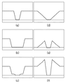
ここで、図2は、本実施形態に係る画像処理において各段階で得られるフレーム画像の波形を示す図で、横軸は画像座標、縦軸は画素値を示す。図2(a)は、着目フレーム画像の波形を示し、図2(b)は、図2(a)に示す波形を有する着目フレーム画像を最小値フィルタ部101に与えた場合の、最小値フィルタ部101による処理結果としての処理済み画像の波形を示している。最小値フィルタ処理では、高輝度の画素値と低輝度の画素値とが隣接しているエッジ領域では低輝度の画素値に更新されるので、エッジは高輝度領域にブロックの半分の長さだけシフトする。
Here, FIG. 2 is a diagram illustrating the waveform of the frame image obtained at each stage in the image processing according to the present embodiment, in which the horizontal axis represents image coordinates, and the vertical axis represents pixel values. 2A shows the waveform of the target frame image, and FIG. 2B shows the minimum value filter when the target frame image having the waveform shown in FIG. The waveform of the processed image as a processing result by the
合成部103は、入力端子150から受けた着目フレーム画像と、最小値フィルタ部101から受けた処理済み画像とを、合成比率aに従って合成することで、合成画像を生成する。即ち、処理済み画像をM、着目フレーム画像をA、合成画像をC、とすると、合成部103は、下記の式に従って合成画像Cを生成する。
The synthesizing
C=a×M+(1−a)×A
係る式は、処理済み画像Mを構成する各画素の画素値をa倍したものと、着目フレーム画像Aを構成する各画素の画素値を(1−a)倍したものとを加算した値を画素値とする画像を、合成画像Cとして生成することを意味している。図2(c)は、合成画像Cの波形を示している。
C = a * M + (1-a) * A
Such an expression is obtained by adding a value obtained by multiplying the pixel value of each pixel constituting the processed image M by a and a value obtained by multiplying the pixel value of each pixel constituting the target frame image A by (1−a). This means that an image having pixel values is generated as a composite image C. FIG. 2C shows the waveform of the composite image C.
最小値強度制御部102は、入力端子150から受けた着目フレーム画像Aと、最小値フィルタ部101から受けた処理済み画像Mとを取得すると、これらを用いて、上記合成比率aを求める処理を行う。即ち、最小値強度制御部102は、合成部103において上記合成処理を行う前に合成比率aを決定し、この決定した合成比率aを合成部103に送出することになる。これにより、合成部103は、最小値強度制御部102から入力した合成比率aを用いて上記合成処理を行う。最小値強度制御部102の詳細については後述する。
When the minimum value
次に、LPF処理部104は、合成部103が生成した合成画像Cに対して2次元のローパスフィルタ処理を施し、低周波数成分で構成されている(低周波数成分のみを含む)画像(低周波数成分画像)を生成する。ここで、ローパスフィルタは、特に関数を規定するものではなく、例えばガウス関数でもよいし、移動平均あるいは重み付け移動平均フィルタのようなものでもよい。
Next, the
図2(d)は、低周波数成分画像の波形を示している。LPF処理部104から出力された低周波数成分画像は、フレームメモリ106に格納されると共に、差分検出部105にも出力される。
FIG. 2D shows the waveform of the low frequency component image. The low frequency component image output from the
差分検出部105は、入力端子150から入力された着目フレーム画像Aから、LPF処理部104から入力された低周波数成分画像を差し引くことで、差分画像を生成する。図2の例では、図2(a)に示した波形を有する着目フレーム画像から、図2(d)に示した波形を有する低周波数成分画像を差し引いた結果が、図2(e)に示した波形を有する差分画像となる。差分検出部105はこの求めた差分画像を、後段の加算器199に送出する。
The
加算器199は、差分検出部105から受けた差分画像と、入力端子150から受けた着目フレーム画像Aと、を合成することで、高周波数成分で構成されている(高周波数成分を強調した)高周波数成分画像を生成する。図2の例では、図2(a)に示した波形を有する着目フレーム画像と、図2(e)に示した波形を有する差分画像と、を合成した結果が、図2(f)に示した波形を有する高周波数成分画像となる。そして加算器199は、この高周波数成分画像を、後段の切替回路107に送出する。
The
切替回路107は、加算器199から送出される高周波数成分画像と、フレームメモリ106に格納されている低周波数成分画像とを交互に読み出し、読み出した方の画像を表示する。これにより、例えば、60Hzで各フレームの画像が入力端子150に入力される場合、切替回路107は120Hzで画像(高周波数成分画像と低周波数成分画像とが交互)を表示することになる。なお、切替回路107で読み出した画像は表示以外に用いても良く、例えばメモリなどに出力しても良い。
The
これにより、切替回路107によって表示された画像をユーザが見ると、視覚的には、60Hz表示におけるフレーム画像の波形(図2(a)に示した波形)と同一の波形として知覚することができる。
Thereby, when the user views the image displayed by the switching
なお、画像がR、G、Bのように1画素が複数の色要素で構成されている場合には、それぞれの色要素について上記処理を行えばよいのであるが、色要素はR、G、Bに限定するものではなく、Y,Cb,Crであっても良い。また、上記処理は、Yのみについて行っても良い。また、R、G、BからYを算出し、算出したYに対して上記処理を行い、その処理結果をR、G、Bに当てはめるようにしても良い。 When an image is composed of a plurality of color elements such as R, G, and B, the above processing may be performed for each color element, but the color elements are R, G, It is not limited to B, and may be Y, Cb, or Cr. The above process may be performed only for Y. Alternatively, Y may be calculated from R, G, and B, the above processing may be performed on the calculated Y, and the processing result may be applied to R, G, and B.
図5は、本実施形態に係る画像処理装置が行う処理のフローチャートである。先ず、ステップS501では、画像処理装置の不図示の制御部は、後述する各処理で用いる変数やパラメータなどを初期化する。例えば最小値フィルタ部101で用いる最小値フィルタのサイズや、LPF処理部104で用いるローパスフィルタの静的特性などを初期化する。
FIG. 5 is a flowchart of processing performed by the image processing apparatus according to the present embodiment. First, in step S501, a control unit (not shown) of the image processing apparatus initializes variables, parameters, and the like used in each process described later. For example, the minimum value filter size used in the minimum
次に、ステップS502では、上記制御部は、本処理を終了するか否かを判断する。本処理を終了する為の条件には様々なものがあり、本実施形態では係る点については主要ではないので、これについての言及は省略する。係る判断の結果、終了する場合には、上記制御部は本処理を終了させるための処理を行うし、終了しない場合には処理をステップS503に勧める。 Next, in step S502, the control unit determines whether or not to end the process. There are various conditions for ending this processing, and since this point is not the main point in this embodiment, reference to this is omitted. As a result of the determination, if the process is to be ended, the control unit performs a process for ending this process, and if not, the process is recommended to step S503.
次に、ステップS503では、入力端子150は、着目フレーム画像Aを取得し、これを、差分検出部105、加算器199、最小値強度制御部102、最小値フィルタ部101、合成部103、に出力する。
Next, in step S503, the
次に、ステップS504では、最小値フィルタ部101は、入力端子150から入力した着目フレーム画像Aに対して最小値フィルタ処理を施すことで、処理済み画像Mを生成し、生成した処理済み画像Mを最小値強度制御部102、合成部103に送出する。
Next, in step S <b> 504, the minimum
次に、ステップS505では、最小値強度制御部102は、入力端子150から受けた着目フレーム画像Aと、最小値フィルタ部101から受けた処理済み画像Mとを取得すると、これらを用いて、上記合成比率aを求める処理を行う。
Next, in step S505, the minimum value
ここで、ステップS505における処理の詳細について、図3に示したフローチャートを用いて説明する。図3は、ステップS505における処理の詳細を示すフローチャートである。なお、図3のフローチャートに従った処理の主体はもちろん最小値強度制御部102である。
Details of the processing in step S505 will be described with reference to the flowchart shown in FIG. FIG. 3 is a flowchart showing details of the process in step S505. 3 is of course the minimum value
先ず、ステップS301では、以下の処理で用いるパラメータなどの初期化処理を行う。例えば、閾値th01、閾値th02にそれぞれ予め定められた値を設定したり、合成比率aを「1.0」に初期化したりする。 First, in step S301, initialization processing such as parameters used in the following processing is performed. For example, a predetermined value is set for each of the threshold th01 and the threshold th02, or the composition ratio a is initialized to “1.0”.
次に、ステップS302では、入力端子150から着目フレーム画像Aを取得する。次にステップS303では、処理済み画像Mと着目フレーム画像Aとを合成部103において合成した場合に、その合成画像Cにおいて最も負の画素値を取りやすいエッジ領域(急峻エッジ領域)を、着目フレーム画像Aから検出する。
Next, in step S302, the frame image A of interest is acquired from the
急峻エッジ領域は、着目フレーム画像A内のコンテンツに応じて、唯一に特定できる、複数特定される、特定できない、の何れかのケースが生じる。急峻エッジ領域が唯一に特定できる場合とは、以下の2つの処理工程によって、着目フレーム画像内で、コントラストの変化率が閾値以上のエッジ領域が1つ特定される場合である。 The steep edge region may occur in any case that can be specified uniquely, specified in plural, or not specified, depending on the content in the frame image A of interest. The case where the steep edge region can be uniquely identified is the case where one edge region whose contrast change rate is equal to or greater than the threshold is identified in the frame image of interest by the following two processing steps.
(処理工程1) 着目フレーム画像Aから検出した1以上のエッジ領域のうち、エッジ領域内のコントラスト変化率が閾値以上(閾値th01以上)を取るエッジ領域を特定する。 (Processing Step 1) Among the one or more edge regions detected from the target frame image A, an edge region in which the contrast change rate in the edge region takes a threshold value or more (threshold value th01 or more) is specified.
(処理工程2) (処理工程1)で特定されたエッジ領域群のうち、エッジ領域内の最低コントラスト値が閾値以上(閾値th02以上)であるエッジ領域群を特定する。そして、特定したエッジ領域群のうち、最も小さい最低コントラスト値を求めたエッジ領域を急峻エッジ領域として特定する。 (Processing Step 2) Among the edge region group specified in (Processing Step 1), an edge region group in which the minimum contrast value in the edge region is not less than a threshold value (threshold value th02 or more) is specified. Then, among the specified edge region group, the edge region for which the smallest minimum contrast value is obtained is specified as the steep edge region.
なお、エッジ領域の検出技術には、様々な技術を適用することができる。例えば、図4に例示したラプラシアンフィルタを用いてエッジの検出を行っても良い。また、コントラスト変化率を求めるためには、様々な方法を適用することができるが、その一例として、ラプラシアンフィルタを用いた出力結果の総和を用いても良い。 Various techniques can be applied to the edge region detection technique. For example, the edge may be detected using a Laplacian filter exemplified in FIG. In addition, various methods can be applied to obtain the contrast change rate. As an example, the sum of output results using a Laplacian filter may be used.
また、急峻エッジ領域が複数特定される場合とは、上記(処理工程1)、(処理工程2)による処理結果として、複数のエッジ領域が特定された場合である。しかし、複数のエッジ領域の何れを用いても後段の処理は同じとなるので、この場合はこの複数のエッジ領域のうち何れか1つを急峻エッジ領域として適当に選択すればよい。 The case where a plurality of steep edge regions are specified is a case where a plurality of edge regions are specified as the processing results of (Processing Step 1) and (Processing Step 2). However, the processing in the subsequent stage is the same regardless of which of the plurality of edge regions is used. In this case, any one of the plurality of edge regions may be appropriately selected as the steep edge region.
また、急峻エッジ領域が特定できない場合とは、上記(処理工程1)、(処理工程2)による処理結果として、1つもエッジ領域が特定されなかった場合である。この場合、合成比率aとしてどのような値を設定しても、結果としての画像の画質の差異は微弱であり、その効果は薄い。 The case where the steep edge region cannot be specified is a case where no edge region is specified as a result of the processing in the above (processing step 1) and (processing step 2). In this case, no matter what value is set as the composition ratio a, the difference in image quality of the resulting image is very weak, and its effect is weak.
次に、ステップS304では、上記ステップS303で急峻エッジが特定できなかったか、合成比率aが決定したか、合成比率aが0.0(±ε≪0)となったか、を判断する。係る判断の結果、何れか1つの条件が満たされている場合には処理をステップS390に進める。一方、何れの条件も満たされていない場合には、処理をステップS306に進める。 Next, in step S304, it is determined whether a steep edge could not be specified in step S303, whether the composition ratio a was determined, or whether the composition ratio a was 0.0 (± ε << 0). As a result of the determination, if any one of the conditions is satisfied, the process proceeds to step S390. On the other hand, if neither condition is satisfied, the process proceeds to step S306.
ステップS390では、この時点での合成比率aを合成部103に送出する。ステップS306では、入力端子150からの着目フレーム画像Aにおける急峻エッジ領域内の画像(第1の画像)と、最小値フィルタ部101からの処理済み画像Mにおいて急峻エッジ領域に対応する領域内の画像(第2の画像)とを合成比率aで合成する。この合成処理(第1手段)は、合成部103が行うものとして上述した合成処理と同じであるが、画像全体同士の合成処理ではなく、急峻エッジ領域同士の合成処理である点のみが異なる。係る処理によれば、画像全体で合成する処理に比べてより高速に合成処理を行うことができる。
In step S390, the composition ratio a at this time is sent to the
次にステップS307では、ステップS306における合成処理で生成された部分合成画像に2次元のローパスフィルタ処理を施し、低周波数成分で構成されている(低周波数成分のみを含む)画像(低周波数成分部分画像)を生成する(第2手段)。 Next, in step S307, a two-dimensional low-pass filter process is performed on the partially combined image generated by the combining process in step S306, and the image (including only the low frequency component) composed of low frequency components (low frequency component portion) Image) is generated (second means).
次に、ステップS309では、入力端子150から入力された着目フレーム画像Aにおける急峻エッジ領域内の画像(第1の画像)から、ステップS307で生成した低周波数成分部分画像を差し引くことで、差分画像を生成する。そして、この差分画像と、入力端子150から受けた着目フレーム画像Aにおける急峻エッジ領域内の画像(第1の画像)と、を合成することで、高周波数成分で構成されている(高周波数成分を強調した)高周波数成分部分画像を生成する(第3手段)。
Next, in step S309, the difference image is obtained by subtracting the low-frequency component partial image generated in step S307 from the image (first image) in the steep edge region in the target frame image A input from the
次に、ステップS310では、ステップS309で生成した高周波数成分部分画像を構成する各画素値を参照し、高周波数成分部分画像を構成する全ての画素値が0以上であるか否かを判断する。即ち、アンダーフローが生じているか否かを判断する。係る判断の結果、高周波数成分部分画像を構成する画素のうち画素値が0より小さい画素が存在する場合には、処理をステップS350に進める。一方、高周波数成分部分画像を構成する全ての画素の画素値が0以上である場合には、処理をステップS311に進める。 Next, in step S310, each pixel value constituting the high-frequency component partial image generated in step S309 is referred to, and it is determined whether or not all pixel values constituting the high-frequency component partial image are 0 or more. . That is, it is determined whether underflow has occurred. If it is determined that there is a pixel having a pixel value smaller than 0 among the pixels constituting the high-frequency component partial image, the process proceeds to step S350. On the other hand, if the pixel values of all the pixels constituting the high frequency component partial image are 0 or more, the process proceeds to step S311.
ステップS350では、合成比率aの値に予め定められた値b(0<b≦1)を加算して合成比率aを更新する。そしてこの更新した合成比率aを最終結果として確定させる。一方、ステップS311では、合成比率aの値から予め定められた値bを減じることで合成比率aを更新する。そしてステップS311,S350の何れの処理の後も、処理をステップS304に戻す。 In step S350, a predetermined value b (0 <b ≦ 1) is added to the value of the composition ratio a to update the composition ratio a. The updated composition ratio a is finalized as a final result. On the other hand, in step S311, the composition ratio a is updated by subtracting a predetermined value b from the value of the composition ratio a. And after any process of step S311 and S350, a process is returned to step S304.
なお、合成比率aを計算する(求める)ための上記処理は一例であり、同様の目的を達成することができるのであれば、他の方法でもって合成比率aを求めても良い。即ち、合成画像における急峻エッジ領域に対応する、高周波数成分画像内の領域を構成する全ての画素値が0以上となるような最小の合成比率aを求めることができるのであれば、他の方法を用いて合成比率aを求めても良い。 Note that the above processing for calculating (determining) the composition ratio a is an example, and the composition ratio a may be obtained by other methods as long as the same object can be achieved. That is, other methods can be used as long as the minimum composition ratio a corresponding to the steep edge region in the composite image can be obtained so that all pixel values constituting the region in the high-frequency component image are 0 or more. May be used to determine the composition ratio a.
図5に戻って次にステップS506では、合成部103は、入力端子150から受けた着目フレーム画像Aと、最小値フィルタ部101から受けた処理済み画像Mとを、上記ステップS505で求めた合成比率aに従って合成することで、合成画像Cを生成する。
Returning to FIG. 5, in step S <b> 506, the
次に、ステップS507では、LPF処理部104は、合成部103が生成した合成画像Cに対して2次元のローパスフィルタ処理を施し、低周波数成分で構成されている(低周波数成分のみを含む)画像(低周波数成分画像)を生成する。この生成された低周波数成分画像は、フレームメモリ106に格納されると共に、差分検出部105にも出力される。
Next, in step S507, the
次に、ステップS508では、差分検出部105は、入力端子150から入力された着目フレーム画像Aから、LPF処理部104から入力された低周波数成分画像を差し引くことで、差分画像を生成する。差分検出部105は、この求めた差分画像を、後段の加算器199に送出する。加算器199は、差分検出部105から受けた差分画像と、入力端子150から受けた着目フレーム画像Aと、を合成することで、高周波数成分で構成されている(高周波数成分を強調した)高周波数成分画像を生成する。そして加算器199は、この高周波数成分画像を、後段の切替回路107に送出する。
Next, in step S508, the
次に、ステップS510では、切替回路107は、高周波数成分画像(第2のサブフレーム画像)、低周波数成分画像(第1のサブフレーム画像)の何れを表示するタイミングであるのかを判断する。上述の取り、切替回路107は、例えば120Hzで第1のサブフレーム画像、第2のサブフレーム画像を交互に表示するので、現タイミングで何れのサブフレーム画像を表示するのかを判断する。そして第1のサブフレーム画像を表示する場合には処理をステップS511に進めるし、第2のサブフレーム画像を表示する場合には処理をステップS512に進める。
Next, in step S510, the
ステップS511では切替回路107は、第1のサブフレーム画像として低周波数成分画像を表示するし、ステップS512では切替回路107は、第2のサブフレーム画像として高周波数成分画像を表示する。
In step S511, the
即ち、切替回路107は、着目フレーム画像Aの代わりに高周波数成分画像と低周波数成分画像とを順次出力することで、倍速表示を可能にしている。ホールド型の表示装置の場合、最初の1/120秒の間に第1のサブフレーム画像を表示し、次の1/120秒の間に第2のサブフレーム画像を表示することになる。
That is, the
なお、液晶の応答特性の改善や、バックライトを制御するなどの方法により、1/120秒よりも短い時間でサブフレーム画像を表示させることも可能である。しかし、1/60秒の時間周期で入力と見かけ上同じ波形を生成する、という本実施形態の特徴は何ら変わるものではない。 Note that a subframe image can be displayed in a time shorter than 1/120 seconds by improving the response characteristics of the liquid crystal or controlling the backlight. However, the feature of the present embodiment that the waveform that is apparently the same as the input is generated in a time period of 1/60 seconds does not change at all.
以上の説明により、本実施形態によれば、最小値フィルタを用いて駆動分配処理(倍速表示)した場合でも、絵柄が動いているときにゴーストを最小化することにより画質劣化を低減することができる。 As described above, according to the present embodiment, even when drive distribution processing (double speed display) is performed using a minimum value filter, it is possible to reduce image quality degradation by minimizing a ghost when a pattern is moving. it can.
[第2の実施形態]
本実施形態では、インパルス型の表示装置としての画像処理装置について説明する。図7は、本実施形態に係る画像処理装置の機能構成例を示すブロック図である。なお、図7と図1とで同じ構成要素については同じ参照番号を付している。また、本実施形態において、特に説明しない点については、第1の実施形態と同じ若しくは同様であるとする。入力端子150を介して入力された着目フレーム画像は、差分検出部105、最小値強度制御部102、最小値フィルタ部101、合成部103、に入力される。
[Second Embodiment]
In the present embodiment, an image processing apparatus as an impulse type display apparatus will be described. FIG. 7 is a block diagram illustrating a functional configuration example of the image processing apparatus according to the present embodiment. 7 and 1 are denoted by the same reference numerals. In the present embodiment, points that are not particularly described are the same as or similar to those in the first embodiment. The frame image of interest input via the
最小値フィルタ部101は、着目フレーム画像に対して第1の実施形態と同様の最小値フィルタ処理を施すことで、処理済み画像を生成し、生成した処理済み画像を最小値強度制御部102、合成部103に送出する。
The minimum
ここで、図8は、本実施形態に係る画像処理において各段階で得られるフレーム画像の波形を示す図で、横軸は画像座標、縦軸は画素値を示す。図8(a)は、着目フレーム画像の波形を示し、図8(b)は、図8(a)に示す波形を有する着目フレーム画像を最小値フィルタ部101に与えた場合の、最小値フィルタ部101による処理結果としての処理済み画像の波形を示している。最小値フィルタ処理では、高輝度の画素値と低輝度の画素値とが隣接しているエッジ領域では低輝度の画素値に更新されるので、エッジは高輝度領域にブロックの半分の長さだけシフトする。
Here, FIG. 8 is a diagram showing the waveform of the frame image obtained at each stage in the image processing according to the present embodiment, in which the horizontal axis indicates image coordinates and the vertical axis indicates pixel values. 8A shows the waveform of the target frame image, and FIG. 8B shows the minimum value filter when the target frame image having the waveform shown in FIG. The waveform of the processed image as a processing result by the
合成部103は、入力端子150から受けた着目フレーム画像と、最小値フィルタ部101から受けた処理済み画像とを、合成比率aに従って合成することで、合成画像を生成する。係る合成処理については第1の実施形態で説明したとおりである。図8(c)は、合成画像の波形を示している。
The synthesizing
最小値強度制御部102は、入力端子150から受けた着目フレーム画像と、最小値フィルタ部101から受けた処理済み画像とを取得すると、これらを用いて、上記合成比率aを求める処理を行う。本実施形態では、最小値強度制御部102の動作が第1の実施形態とは若干異なる。
When the minimum value
先ず最小値強度制御部102は、以下の処理で用いるパラメータなどの初期化処理を行う。例えば、閾値th01、閾値th02にそれぞれ予め定められた値を設定したり、合成比率aを「1.0」に初期化したりする。
First, the minimum value
次に、最小値強度制御部102は、入力端子150から着目フレーム画像を取得し、この着目フレーム画像から上記急峻エッジ領域を、第1の実施形態と同様にして取得する。
Next, the minimum value
次に、最小値強度制御部102は、急峻エッジが特定できなかったか、合成比率aが決定したか、合成比率aが0.0(±ε≪0)となったか、を判断し、何れか1つの条件が満たされている場合には、この時点での合成比率aを合成部103に送出する。一方、何れの条件も満たされていない場合には、入力端子150からの着目フレーム画像における急峻エッジ領域内の画像と、最小値フィルタ部101からの処理済み画像において急峻エッジ領域に対応する領域内の画像とを合成比率aで合成する。
Next, the minimum value
次に、最小値強度制御部102は、この合成処理で生成された部分合成画像に2次元のローパスフィルタ処理を施し、低周波数成分で構成されている(低周波数成分のみを含む)画像(低周波数成分部分画像)を生成する。
Next, the minimum value
次に、最小値強度制御部102は、この低周波数成分部分画像を構成する各画素の輝度値を下げる(例えば50%下げる)ことで、この低周波数成分部分画像を更新する。次に、最小値強度制御部102は、入力端子150から入力された着目フレーム画像における急峻エッジ領域内の画像から、上記更新した低周波数成分部分画像を差し引くことで、差分画像を生成する。
Next, the minimum value
次に、最小値強度制御部102は、この差分画像を構成する各画素値を参照し、差分画像を構成する全ての画素値が0以上であるか否かを判断する。即ち、アンダーフローが生じているか否かを判断する。係る判断の結果、差分画像を構成する画素のうち画素値が0より小さい画素が存在する場合には、合成比率aの値に予め定められた値b(0<b≦1)を加算して合成比率aを更新する。そしてこの更新した合成比率aを最終結果として確定させる。一方、差分画像を構成する全ての画素の画素値が0以上である場合には、合成比率aの値から予め定められた値bを減じることで合成比率aを更新する。そして合成比率aが確定していない限りは、この更新した合成比率aを用いて、上記部分合成画像を作成する以降の処理を繰り返す。これにより、合成比率aを確定させる。
Next, the minimum value
もちろん、本実施形態においても、合成比率aを求めるための上記処理は一例であり、同様の目的を達成することができるのであれば、他の方法でもって合成比率aを求めても良い。 Of course, also in the present embodiment, the above-described processing for obtaining the composition ratio a is an example, and the composition ratio a may be obtained by other methods as long as the same object can be achieved.
そして最小値強度制御部102は、このようにして確定させた合成比率aを、第1の実施形態と同様に、合成部103に設定する。次に、LPF処理部104は、合成部103が生成した合成画像に対して2次元のローパスフィルタ処理を施し、低周波数成分で構成されている(低周波数成分のみを含む)画像(低周波数成分画像)を生成する。ここで、ローパスフィルタは、特に関数を規定するものではなく、例えばガウス関数でもよいし、移動平均あるいは重み付け移動平均フィルタのようなものでもよい。
Then, the minimum value
図8(d)は、低周波数成分画像の波形を示している。LPF処理部104から出力された低周波数成分画像は、ゲイン補正部706に出力される。ゲイン補正部706は、LPF処理部104から送出された低周波数成分画像を構成する各画素の輝度値を下げる(例えば50%下げる)ことで、この低周波数成分画像に対してゲイン補正処理を施し、この低周波数成分画像を更新する。図8(e)は、図8(d)に示した波形を有する低周波数成分画像を構成する各画素の画素値に0.5を乗じて得た画像の波形を示している。なお、ゲイン補正部706により得られる更新済みの低周波数成分画像を第1のサブフレーム画像と呼称する場合がある。そしてゲイン補正部706は、この求めた第1のサブフレーム画像を後段の切替回路107に送出する。
FIG. 8D shows the waveform of the low frequency component image. The low frequency component image output from the
一方、差分検出部105は、入力端子150から入力された着目フレーム画像から、ゲイン補正部706によって得られた第1のサブフレーム画像を差し引くことで、この差分画像を第2のサブフレーム画像として求める。図8(f)は、図8(a)に示した波形を有する着目フレーム画像Aから、図8(e)に示した波形を有する更新済みの低周波数成分画像を差し引くことで得られる第2のサブフレーム画像の波形を示している。そして差分検出部105は、この求めた第2のサブフレーム画像を後段の切替回路107に送出する。
On the other hand, the
切替回路107では、所望のタイミング、例えば入力60Hzの場合、120Hzの周期で、2つのサブフレーム(第1のサブフレーム画像、第2のサブフレーム画像)を交互に表示する。図8(f)に示した波形を有するサブフレーム画像と、図8(e)に示した波形を有するサブフレーム画像とを高速に交互表示すると、視覚的には60Hz表示における入力フレーム画像(図8(a))と同一の波形として知覚することができる。
The
このように、ホールド型とインパルス型とでは、サブフレーム画像の生成形態が異なるが、入力フレーム画像から低域成分のみを含むサブフレーム画像を減じた場合に、負値を取らないという点が、共通する処理である。 In this way, the generation type of the subframe image is different between the hold type and the impulse type, but when the subframe image including only the low frequency component is subtracted from the input frame image, it does not take a negative value. This is a common process.
図9は、本実施形態に係る画像処理装置が行う処理のフローチャートである。先ず、ステップS901では、画像処理装置の不図示の制御部は、後述する各処理で用いる変数やパラメータなどを初期化する。例えば最小値フィルタ部101で用いる最小値フィルタのサイズや、LPF処理部104で用いるローパスフィルタの静的特性や、ゲイン補正部706で用いるゲイン補正量、などを初期化する。
FIG. 9 is a flowchart of processing performed by the image processing apparatus according to the present embodiment. First, in step S901, a control unit (not shown) of the image processing apparatus initializes variables, parameters, and the like used in each process described later. For example, the minimum value filter size used in the minimum
次に、ステップS902では、上記制御部は、本処理を終了するか否かを判断する。本処理を終了する為の条件には様々なものがあり、本実施形態では係る点については主要ではないので、これについての言及は省略する。係る判断の結果、終了する場合には、上記制御部は本処理を終了させるための処理を行うし、終了しない場合には処理をステップS903に勧める。 In step S902, the control unit determines whether to end the process. There are various conditions for ending this processing, and since this point is not the main point in this embodiment, reference to this is omitted. As a result of the determination, if the process is to be ended, the control unit performs a process for ending this process, and if not, the process is recommended to step S903.
次に、ステップS903では、入力端子150は、着目フレーム画像を取得し、取得した着目フレーム画像を、差分検出部105、最小値強度制御部102、最小値フィルタ部101、合成部103、に出力する。
Next, in step S903, the
次に、ステップS904では、最小値フィルタ部101は、入力端子150から入力した着目フレーム画像に対して最小値フィルタ処理を施すことで、処理済み画像を生成し、生成した処理済み画像を最小値強度制御部102、合成部103に送出する。
Next, in step S <b> 904, the minimum
次に、ステップS905では、最小値強度制御部102は、入力端子150から受けた着目フレーム画像と、最小値フィルタ部101から受けた処理済み画像とを取得すると、これらを用いて、上記合成比率aを求める処理を行う。
Next, in step S905, when the minimum value
次に、ステップS906では、合成部103は、入力端子150から受けた着目フレーム画像と、最小値フィルタ部101から受けた処理済み画像とを、上記ステップS905で求めた合成比率aに従って合成することで、合成画像を生成する。
Next, in step S906, the
次に、ステップS907では、LPF処理部104は、合成部103が生成した合成画像に対して2次元のローパスフィルタ処理を施し、低周波数成分で構成されている(低周波数成分のみを含む)画像(低周波数成分画像)を生成する。この生成された低周波数成分画像は、ゲイン補正部706に出力される。
Next, in step S907, the
次に、ステップS908では、ゲイン補正部706は、LPF処理部104から送出された低周波数成分画像を構成する各画素の輝度値を下げる(例えば50%下げる)ことで、この低周波数成分画像に対してゲイン補正処理を施す。これにより、この低周波数成分画像を第1のサブフレーム画像として更新する。
Next, in step S908, the
次に、ステップS909では、差分検出部105は、入力端子150から入力された着目フレーム画像から、ゲイン補正部706によって得られた第1のサブフレーム画像を差し引くことで、この差分画像を第2のサブフレーム画像として求める。
Next, in step S909, the
次に、ステップS910では、切替回路107は、高周波数成分画像(第2のサブフレーム画像)、低周波数成分画像(第1のサブフレーム画像)の何れを表示するタイミングであるのかを判断する。上述の取り、切替回路107は、例えば120Hzで第1のサブフレーム画像、第2のサブフレーム画像を交互に表示するので、現タイミングで何れのサブフレーム画像を表示するのかを判断する。そして第1のサブフレーム画像を表示する場合には処理をステップS911に進めるし、第2のサブフレーム画像を表示する場合には処理をステップS912に進める。
Next, in step S910, the
ステップS911では切替回路107は、第1のサブフレーム画像として低周波数成分画像を表示するし、ステップS912では切替回路107は、第2のサブフレーム画像として高周波数成分画像を表示する。
In step S911, the
第1のサブフレーム画像のエッジ勾配領域とエッジにおけるゲイン差が最小化されている点が、本実施形態の特徴部分である。インパルス型の表示装置の場合、最初の1/120秒の瞬間に第1のサブフレーム画像を表示し、次の1/120秒の瞬間に第2のサブフレーム画像を表示することになる。1/60秒の時間平均での見かけの波形は、入力フレーム画像と同じ波形となる。 The feature of this embodiment is that the gain difference between the edge gradient region and the edge of the first sub-frame image is minimized. In the case of the impulse-type display device, the first subframe image is displayed at the first 1/120 second, and the second subframe image is displayed at the next 1/120 second. The apparent waveform with a time average of 1/60 seconds is the same as that of the input frame image.
[第3の実施形態]
本実施形態では、ホールド型の表示装置としての画像処理装置について説明する。なお、本実施形態は第1の実施形態と類似しているため、本実施形態において第1の実施形態と同じ部分についてはその説明を省略する。
[Third Embodiment]
In the present embodiment, an image processing apparatus as a hold-type display device will be described. In addition, since this embodiment is similar to 1st Embodiment, the description about the part same as 1st Embodiment in this embodiment is abbreviate | omitted.
図14は、本実施形態に係る画像処理装置の機能構成例を示すブロック図である。なお、図14と図1とで同じ構成要素については同じ参照番号を付けており、その説明は省略する。 FIG. 14 is a block diagram illustrating a functional configuration example of the image processing apparatus according to the present embodiment. 14 and 1 are denoted by the same reference numerals, and the description thereof is omitted.
合成部103では第1の実施形態と同様、最小値フィルタ部101が生成した処理済み画像と、着目フレーム画像とを、合成比率aに基づいて合成するが、この合成比率aが0.0に初期化されているものとする。また、この合成比率aは、この後、最小値強度制御部2202によって更新されうるのであるが、最小値強度制御部2202で用いる合成比率aは0.0に初期化されているものとする。
As in the first embodiment, the synthesizing
合成比率aを0.0に初期化して最小値フィルタ部101、合成部103、LPF処理部104、差分検出部105、加算器199を動作させると、フレームメモリ106には低周波数成分画像が格納されることになる。更に、最小値強度制御部2202には加算器199から高周波数成分画像が入力されることになる。
When the synthesis ratio a is initialized to 0.0 and the minimum
最小値強度制御部2202は、加算器199から高周波数成分画像を受けると、この高周波数成分画像を構成する各画素値を参照し、0より小さい画素値を有する画素が存在するか否かを判断する。存在しない場合には、加算器199から受けた高周波数成分画像をそのまま後段の切替回路107に送出する。一方、存在する場合には、最小値強度制御部2202に設定されている合成比率aの値に予め定められた値b(0<b≦1)を加算して合成比率aを更新する。そしてこの更新した合成比率aを最終結果として確定させ、この確定させた合成比率aを合成部103に設定する。そして最小値強度制御部2202は、この新たに設定した合成比率aを用いて再度、合成処理を合成部103に実行させる。
When the minimum value
もちろん、LPF処理部104は、この合成部103が再度実行した合成処理(最小値強度制御部2202によって更新された合成比率aを用いた合成処理)によって生成された合成画像を用いて低周波数成分画像を新たに生成する。また、差分検出部105は、加算器199は、この新たに生成された低周波数成分画像と着目フレーム画像とを用いて新たに高周波数成分画像を生成する。そして最小値強度制御部2202は、この新たに生成された高周波数成分画像を後段の切替回路107に送出する。
Of course, the
係る構成により、切替回路107から出力され、表示される画像をユーザが見た場合、視覚的には、60Hz表示における入力フレーム画像の波形(図3(a))と同一の波形として知覚させることができる。
With such a configuration, when the user views the image that is output from the switching
本実施形態が第1の実施形態と大きく異なるのは、第1の実施形態では、着目フレーム画像を解析して合成比率aを算出するのに対し、本実施形態では、高周波数成分画像を解析して合成比率aを算出する点にある。換言すると、第1の実施形態に係る画像処理装置は、フィードフォワード制御を行っているのに対し、本実施形態に係る画像処理装置は、フィードバック制御を行っている。また、本実施形態では、最小値強度制御部2202で行う処理は第1の実施形態に比べて簡素であるため、画像処理装置全体の構成をより簡素に構成することができる。
The present embodiment is significantly different from the first embodiment. In the first embodiment, the target frame image is analyzed to calculate the synthesis ratio a, whereas in the present embodiment, the high frequency component image is analyzed. Thus, the composite ratio a is calculated. In other words, the image processing apparatus according to the first embodiment performs feedforward control, whereas the image processing apparatus according to the present embodiment performs feedback control. In the present embodiment, the processing performed by the minimum value
[第4の実施形態]
本実施形態では、インパルス型の表示装置としての画像処理装置について説明する。なお、本実施形態は第2の実施形態と類似しているため、本実施形態において第2の実施形態と同じ部分についてはその説明を省略する。
[Fourth Embodiment]
In the present embodiment, an image processing apparatus as an impulse type display apparatus will be described. In addition, since this embodiment is similar to 2nd Embodiment, the description about the part same as 2nd Embodiment in this embodiment is abbreviate | omitted.
図15は、本実施形態に係る画像処理装置の機能構成例を示すブロック図である。なお、図15と図1、7とで同じ構成要素については同じ参照番号を付けており、その説明は省略する。 FIG. 15 is a block diagram illustrating a functional configuration example of the image processing apparatus according to the present embodiment. Note that the same reference numerals are given to the same components in FIG. 15 and FIGS.
合成部103では第1の実施形態と同様、最小値フィルタ部101が生成した処理済み画像と、着目フレーム画像とを、合成比率aに基づいて合成するのが、この合成比率aが0.0に初期化されているものとする。また、この合成比率aは、この後、最小値強度制御部2302によって更新されうるのであるが、最小値強度制御部2302で用いる合成比率aは0.0に初期化されているものとする。
As in the first embodiment, the
合成比率aを0.0に初期化して最小値フィルタ部101、合成部103、LPF処理部104、ゲイン補正部706、差分検出部105、を動作させると、ゲイン補正部706からは低周波数成分画像が出力されることになる。更に、差分検出部105からは最小値強度制御部2302に対して差分画像が入力されることになる。
When the synthesis ratio a is initialized to 0.0 and the minimum
最小値強度制御部2302は、差分検出部105から差分画像を受けると、この差分画像を構成する各画素値を参照し、0より小さい画素値を有する画素が存在するか否かを判断する。存在しない場合には、差分検出部105から受けた差分画像をそのまま後段の切替回路107に送出する。一方、存在する場合には、最小値強度制御部2302に設定されている合成比率aの値に予め定められた値b(0<b≦1)を加算して合成比率aを更新する。そしてこの更新した合成比率aを最終結果として確定させ、この確定させた合成比率aを合成部103に設定する。そして最小値強度制御部2302は、この新たに設定した合成比率aを用いて再度、合成処理を合成部103に実行させる。
When the minimum value
もちろん、LPF処理部104は、この合成部103が再度実行した合成処理(最小値強度制御部2302によって更新された合成比率aを用いた合成処理)によって生成された合成画像を用いて低周波数成分画像を新たに生成する。また、差分検出部105は、この新たに生成された低周波数成分画像と着目フレーム画像とを用いて新たに差分画像を生成する。そして最小値強度制御部2302は、この新たに生成された差分画像を後段の切替回路107に送出する。
Of course, the
係る構成により、切替回路107から出力され、表示される画像をユーザが見た場合、視覚的には、60Hz表示における入力フレーム画像の波形(図3(a))と同一の波形として知覚させることができる。
With such a configuration, when the user views the image that is output from the switching
本実施形態が第2の実施形態と大きく異なるのは、第2の実施形態では、着目フレーム画像を解析して合成比率aを算出するのに対し、本実施形態では、差分画像を解析して合成比率aを算出する点にある。換言すると、第2の実施形態に係る画像処理装置は、フィードフォワード制御を行っているのに対し、本実施形態に係る画像処理装置は、フィードバック制御を行っている。また、本実施形態では、最小値強度制御部2302で行う処理は第2の実施形態に比べて簡素であるため、画像処理装置全体の構成をより簡素に構成することができる。
The present embodiment is significantly different from the second embodiment. In the second embodiment, the frame image of interest is analyzed to calculate the composition ratio a, whereas in the present embodiment, the difference image is analyzed. The point is to calculate the composition ratio a. In other words, the image processing apparatus according to the second embodiment performs feedforward control, whereas the image processing apparatus according to the present embodiment performs feedback control. Further, in the present embodiment, the processing performed by the minimum value
Claims (14)
着目フレーム画像と、当該着目フレーム画像に対して最小値フィルタ処理を施すことで得られる処理済み画像と、を合成することで合成画像を生成する合成手段と、
前記合成画像に対してローパスフィルタ処理を施すことで、低周波数成分で構成されている低周波数成分画像を生成する手段と、
前記着目フレーム画像と前記低周波数成分画像との差分画像を生成し、生成した差分画像を前記着目フレーム画像に加算することで、高周波数成分で構成されている高周波数成分画像を生成する手段と、
前記高周波数成分画像と前記低周波数成分画像とを、前記着目フレーム画像の代わりに出力する出力手段とを備え、
前記合成手段は、
前記着目フレーム画像内で、コントラストの変化率が閾値以上のエッジ領域を1つ特定する手段と、
前記特定したエッジ領域内の画像を第1の画像、前記エッジ領域に対応する前記処理済み画像内の領域内の画像を第2の画像とし、前記第1の画像と前記第2の画像とを、合成比率aで合成することで部分合成画像を生成する第1手段と、
前記部分合成画像に対してローパスフィルタ処理を施すことで、低周波数成分で構成されている低周波数成分部分画像を生成する第2手段と、
前記第1の画像と前記低周波数成分部分画像との差分画像を生成し、生成した差分画像を前記第1の画像に加算することで、高周波数成分で構成されている高周波数成分部分画像を生成する第3手段と、
前記高周波数成分部分画像を構成する全ての画素値が0以上となるような最小の前記合成比率aを求める計算手段とを備え、
前記合成手段は、前記計算手段が求めた合成比率aで、前記処理済み画像と前記着目フレーム画像とを合成することで前記合成画像を生成する
ことを特徴とする画像処理装置。 An image processing apparatus that processes an image of each frame constituting a moving image,
A synthesizing unit that generates a synthesized image by synthesizing the target frame image and a processed image obtained by performing a minimum value filtering process on the target frame image;
Means for generating a low-frequency component image composed of low-frequency components by performing low-pass filter processing on the synthesized image;
Means for generating a high-frequency component image composed of high-frequency components by generating a differential image between the frame-of-interest image and the low-frequency component image, and adding the generated differential image to the frame-of-interest image; ,
Output means for outputting the high frequency component image and the low frequency component image instead of the frame image of interest;
The synthesis means includes
Means for identifying one edge region having a contrast change rate equal to or greater than a threshold in the frame image of interest;
The image in the specified edge region is a first image, the image in the region in the processed image corresponding to the edge region is a second image, and the first image and the second image are First means for generating a partial composite image by combining at a composite ratio a;
A second means for generating a low-frequency component partial image composed of low-frequency components by performing low-pass filter processing on the partial composite image;
By generating a difference image between the first image and the low frequency component partial image, and adding the generated difference image to the first image, a high frequency component partial image composed of high frequency components is obtained. A third means for generating;
Calculating means for obtaining the minimum composition ratio a such that all pixel values constituting the high-frequency component partial image are 0 or more;
The image processing apparatus, wherein the combining unit generates the combined image by combining the processed image and the frame image of interest with the combining ratio a obtained by the calculating unit.
前記第1手段、前記第2手段、前記第3手段によって求めた前記高周波数成分部分画像を構成する全ての画素の画素値が0以上である場合には、合成比率aの値から予め定められた値を減じることで合成比率aを更新し、更新した合成比率aを用いて再度、前記第1手段、前記第2手段、前記第3手段、を実行させ、
前記第1手段、前記第2手段、前記第3手段によって求めた前記高周波数成分部分画像を構成する画素のうち画素値が0より小さい画素が存在する場合には、合成比率aの値に予め定められた値を加算して合成比率aを更新し、更新した合成比率aを前記最小の合成比率aとする
ことを特徴とする請求項1又は2に記載の画像処理装置。 The calculating means includes
When the pixel values of all the pixels constituting the high-frequency component partial image obtained by the first means, the second means, and the third means are 0 or more, they are determined in advance from the value of the composition ratio a. The composite ratio a is updated by subtracting the updated value, and the first means, the second means, and the third means are executed again using the updated composite ratio a.
If there is a pixel having a pixel value smaller than 0 among the pixels constituting the high-frequency component partial image obtained by the first means, the second means, and the third means, the value of the composition ratio a is set in advance. The image processing apparatus according to claim 1, wherein the composition ratio a is updated by adding a predetermined value, and the updated composition ratio a is set as the minimum composition ratio a.
着目フレーム画像と、当該着目フレーム画像に対して最小値フィルタ処理を施すことで得られる処理済み画像と、を合成することで合成画像を生成する合成手段と、
前記合成画像に対してローパスフィルタ処理を施すことで、低周波数成分で構成されている低周波数成分画像を生成する第1手段と、
前記着目フレーム画像と前記低周波数成分画像との差分画像を生成し、生成した差分画像を前記着目フレーム画像に加算することで、高周波数成分で構成されている高周波数成分画像を生成する第2手段と、
前記高周波数成分画像を構成する全ての画素値が0以上となるような最小の合成比率aを求める手段と、
前記合成手段に前記合成比率aを用いて再度、合成処理を実行させる制御手段と、
前記制御手段により制御された前記合成手段が生成した合成画像を用いて前記第1手段が生成した低周波数成分画像と、当該低周波数成分画像と前記着目フレーム画像とを用いて前記第2手段が生成した高周波数成分画像と、を前記着目フレーム画像の代わりに出力する出力手段と
を備えることを特徴とする画像処理装置。 An image processing apparatus that processes an image of each frame constituting a moving image,
A synthesizing unit that generates a synthesized image by synthesizing the target frame image and a processed image obtained by performing a minimum value filtering process on the target frame image;
First means for generating a low-frequency component image composed of low-frequency components by performing low-pass filter processing on the synthesized image;
Generating a difference image between the frame image of interest and the low frequency component image, and adding the generated difference image to the frame of interest image to generate a high frequency component image composed of high frequency components; Means,
Means for obtaining a minimum composition ratio a such that all pixel values constituting the high-frequency component image are 0 or more;
Control means for causing the synthesis means to execute the synthesis process again using the synthesis ratio a;
The second means uses the low-frequency component image generated by the first means using the synthesized image generated by the synthesizing means controlled by the control means, and the low-frequency component image and the frame image of interest. An image processing apparatus comprising: output means for outputting the generated high-frequency component image instead of the frame image of interest.
前記制御手段は前記合成手段に合成処理を実行させず、
前記出力手段は、前記第1手段が生成した低周波数成分画像と、前記第2手段が生成した高周波数成分画像とを、前記着目フレーム画像の代わりに出力する
ことを特徴とする請求項4に記載の画像処理装置。 When pixel values of all pixels constituting the high-frequency component image generated by the second means are 0 or more,
The control means does not cause the synthesizing means to execute a synthesizing process,
The output means outputs the low frequency component image generated by the first means and the high frequency component image generated by the second means instead of the frame image of interest. The image processing apparatus described.
着目フレーム画像と、当該着目フレーム画像に対して最小値フィルタ処理を施すことで得られる処理済み画像と、を合成することで合成画像を生成する合成手段と、
前記合成画像に対してローパスフィルタ処理を施すことで、低周波数成分で構成されている低周波数成分画像を生成する手段と、
前記低周波数成分画像に対してゲイン補正処理を施すことで、前記低周波数成分画像を更新する更新手段と、
前記更新手段によって更新された前記低周波数成分画像と前記着目フレーム画像との差分画像を生成する手段と、
前記差分画像と前記低周波数成分画像とを、前記着目フレーム画像の代わりに出力する出力手段とを備え、
前記合成手段は、
前記着目フレーム画像内で、コントラストの変化率が閾値以上のエッジ領域を1つ特定する手段と、
前記特定したエッジ領域内の画像を第1の画像、前記エッジ領域に対応する前記処理済み画像内の領域内の画像を第2の画像とし、前記第1の画像と前記第2の画像とを、合成比率aで合成することで部分合成画像を生成する第1手段と、
前記部分合成画像に対してローパスフィルタ処理を施すことで、低周波数成分で構成されている低周波数成分部分画像を生成する第2手段と、
前記低周波数成分部分画像に対してゲイン補正処理を施すことで前記低周波数成分部分画像を更新し、更新した低周波数成分部分画像と、前記第1の画像と、の差分画像を生成する第3手段と、
前記第3手段が生成した差分画像を構成する全ての画素値が0以上となるような最小の前記合成比率aを求める計算手段とを備え、
前記合成手段は、前記計算手段が求めた合成比率aで、前記処理済み画像と前記着目フレーム画像とを合成することで前記合成画像を生成する
ことを特徴とする画像処理装置。 An image processing apparatus that processes an image of each frame constituting a moving image,
A synthesizing unit that generates a synthesized image by synthesizing the target frame image and a processed image obtained by performing a minimum value filtering process on the target frame image;
Means for generating a low-frequency component image composed of low-frequency components by performing low-pass filter processing on the synthesized image;
Update means for updating the low frequency component image by performing gain correction processing on the low frequency component image;
Means for generating a difference image between the low-frequency component image updated by the update means and the frame image of interest;
Output means for outputting the difference image and the low-frequency component image instead of the frame image of interest;
The synthesis means includes
Means for identifying one edge region having a contrast change rate equal to or greater than a threshold in the frame image of interest;
The image in the specified edge region is a first image, the image in the region in the processed image corresponding to the edge region is a second image, and the first image and the second image are First means for generating a partial composite image by combining at a composite ratio a;
A second means for generating a low-frequency component partial image composed of low-frequency components by performing low-pass filter processing on the partial composite image;
The low frequency component partial image is updated by applying a gain correction process to the low frequency component partial image, and a difference image between the updated low frequency component partial image and the first image is generated. Means,
Calculating means for obtaining the minimum composition ratio a such that all pixel values constituting the difference image generated by the third means are 0 or more;
The image processing apparatus, wherein the combining unit generates the combined image by combining the processed image and the frame image of interest with the combining ratio a obtained by the calculating unit.
前記第1手段、前記第2手段、前記第3手段によって求めた差分画像を構成する全ての画素の画素値が0以上である場合には、合成比率aの値から予め定められた値を減じることで合成比率aを更新し、更新した合成比率aを用いて再度、前記第1手段、前記第2手段、前記第3手段、を実行させ、
前記第1手段、前記第2手段、前記第3手段によって求めた差分画像を構成する画素のうち画素値が0より小さい画素が存在する場合には、合成比率aの値に予め定められた値を加算して合成比率aを更新し、更新した合成比率aを前記最小の合成比率aとする
ことを特徴とする請求項7に記載の画像処理装置。 The calculating means includes
When the pixel values of all the pixels constituting the difference image obtained by the first means, the second means, and the third means are 0 or more, a predetermined value is subtracted from the value of the composition ratio a. Then, the composite ratio a is updated, and the first means, the second means, and the third means are executed again using the updated composite ratio a.
When there is a pixel having a pixel value smaller than 0 among the pixels constituting the difference image obtained by the first means, the second means, and the third means, a value predetermined as the value of the composition ratio a The image processing apparatus according to claim 7, wherein the composition ratio a is updated by adding and the updated composition ratio a is set to the minimum composition ratio a.
着目フレーム画像と、当該着目フレーム画像に対して最小値フィルタ処理を施すことで得られる処理済み画像と、を合成することで合成画像を生成する合成手段と、
前記合成画像に対してローパスフィルタ処理を施すことで、低周波数成分で構成されている低周波数成分画像を生成する第1手段と、
前記低周波数成分画像に対してゲイン補正処理を施すことで、前記低周波数成分画像を更新する更新手段と、
前記更新手段によって更新された前記低周波数成分画像と前記着目フレーム画像との差分画像を生成する第2手段と、
前記差分画像を構成する全ての画素値が0以上となるような最小の合成比率aを求める計算手段と、
前記合成手段に前記合成比率aを用いて再度、合成処理を実行させる制御手段と、
前記制御手段により制御された前記合成手段が生成した合成画像を用いて前記第1手段、前記更新手段が生成した低周波数成分画像と、当該低周波数成分画像と前記着目フレーム画像とを用いて前記第2手段が生成した差分画像を、前記着目フレーム画像の代わりに出力する出力手段と
を備えることを特徴とする画像処理装置。 An image processing apparatus that processes an image of each frame constituting a moving image,
A synthesizing unit that generates a synthesized image by synthesizing the target frame image and a processed image obtained by performing a minimum value filtering process on the target frame image;
First means for generating a low-frequency component image composed of low-frequency components by performing low-pass filter processing on the synthesized image;
Update means for updating the low frequency component image by performing gain correction processing on the low frequency component image;
Second means for generating a difference image between the low frequency component image updated by the updating means and the frame image of interest;
Calculation means for obtaining a minimum composition ratio a such that all pixel values constituting the difference image are 0 or more;
Control means for causing the synthesis means to execute the synthesis process again using the synthesis ratio a;
The first means using the synthesized image generated by the synthesizing means controlled by the control means, the low frequency component image generated by the updating means, the low frequency component image and the frame image of interest using the low frequency component image An image processing apparatus comprising: output means for outputting the difference image generated by the second means instead of the frame image of interest.
着目フレーム画像と、当該着目フレーム画像に対して最小値フィルタ処理を施すことで得られる処理済み画像と、を合成することで合成画像を生成する合成工程と、
前記合成画像に対してローパスフィルタ処理を施すことで、低周波数成分で構成されている低周波数成分画像を生成する工程と、
前記着目フレーム画像と前記低周波数成分画像との差分画像を生成し、生成した差分画像を前記着目フレーム画像に加算することで、高周波数成分で構成されている高周波数成分画像を生成する工程と、
前記高周波数成分画像と前記低周波数成分画像とを、前記着目フレーム画像の代わりに出力する出力工程とを備え、
前記合成工程は、
前記着目フレーム画像内で、コントラストの変化率が閾値以上のエッジ領域を1つ特定する工程と、
前記特定したエッジ領域内の画像を第1の画像、前記エッジ領域に対応する前記処理済み画像内の領域内の画像を第2の画像とし、前記第1の画像と前記第2の画像とを、合成比率aで合成することで部分合成画像を生成する第1工程と、
前記部分合成画像に対してローパスフィルタ処理を施すことで、低周波数成分で構成されている低周波数成分部分画像を生成する第2工程と、
前記第1の画像と前記低周波数成分部分画像との差分画像を生成し、生成した差分画像を前記第1の画像に加算することで、高周波数成分で構成されている高周波数成分部分画像を生成する第3工程と、
前記高周波数成分部分画像を構成する全ての画素値が0以上となるような最小の前記合成比率aを求める計算工程とを備え、
前記合成工程では、前記計算工程で求めた合成比率aで、前記処理済み画像と前記着目フレーム画像とを合成することで前記合成画像を生成する
ことを特徴とする画像処理方法。 An image processing method performed by an image processing apparatus that processes an image of each frame constituting a moving image,
A synthesizing step of generating a synthesized image by synthesizing the target frame image and a processed image obtained by performing minimum value filter processing on the target frame image;
A step of generating a low-frequency component image composed of low-frequency components by performing low-pass filter processing on the synthesized image;
Generating a difference image between the frame-of-interest image and the low-frequency component image, and adding the generated difference image to the frame-of-interest image to generate a high-frequency component image composed of high-frequency components; ,
An output step of outputting the high-frequency component image and the low-frequency component image instead of the frame image of interest;
The synthesis step includes
Identifying one edge region having a contrast change rate equal to or higher than a threshold in the frame image of interest;
The image in the specified edge region is a first image, the image in the region in the processed image corresponding to the edge region is a second image, and the first image and the second image are A first step of generating a partially combined image by combining at a combining ratio a;
A second step of generating a low-frequency component partial image composed of low-frequency components by performing low-pass filter processing on the partial composite image;
By generating a difference image between the first image and the low frequency component partial image, and adding the generated difference image to the first image, a high frequency component partial image composed of high frequency components is obtained. A third step to generate;
A calculation step for obtaining a minimum composition ratio a such that all pixel values constituting the high-frequency component partial image are 0 or more,
In the synthesis step, the synthesized image is generated by synthesizing the processed image and the frame image of interest with the synthesis ratio a obtained in the calculation step.
着目フレーム画像と、当該着目フレーム画像に対して最小値フィルタ処理を施すことで得られる処理済み画像と、を合成することで合成画像を生成する合成工程と、
前記合成画像に対してローパスフィルタ処理を施すことで、低周波数成分で構成されている低周波数成分画像を生成する第1工程と、
前記着目フレーム画像と前記低周波数成分画像との差分画像を生成し、生成した差分画像を前記着目フレーム画像に加算することで、高周波数成分で構成されている高周波数成分画像を生成する第2工程と、
前記高周波数成分画像を構成する全ての画素値が0以上となるような最小の合成比率aを求める工程と、
前記合成比率aを用いて再度、前記合成工程を実行する制御工程と、
前記制御工程で制御された前記合成工程で生成した合成画像を用いて前記第1工程で生成した低周波数成分画像と、当該低周波数成分画像と前記着目フレーム画像とを用いて前記第2工程で生成した高周波数成分画像と、を前記着目フレーム画像の代わりに出力する出力工程と
を備えることを特徴とする画像処理方法。 An image processing method performed by an image processing apparatus that processes an image of each frame constituting a moving image,
A synthesis step of generating a synthesized image by synthesizing the frame of interest image and a processed image obtained by performing minimum value filter processing on the frame of interest image;
A first step of generating a low-frequency component image composed of low-frequency components by performing low-pass filter processing on the synthesized image;
Generating a difference image between the frame image of interest and the low frequency component image, and adding the generated difference image to the frame of interest image to generate a high frequency component image composed of high frequency components; Process,
Obtaining a minimum composition ratio a such that all pixel values constituting the high frequency component image are 0 or more;
A control step of executing the synthesis step again using the synthesis ratio a;
In the second step using the low frequency component image generated in the first step using the composite image generated in the combining step controlled in the control step, the low frequency component image and the frame image of interest. An image processing method comprising: an output step of outputting the generated high frequency component image instead of the frame image of interest.
着目フレーム画像と、当該着目フレーム画像に対して最小値フィルタ処理を施すことで得られる処理済み画像と、を合成することで合成画像を生成する合成工程と、
前記合成画像に対してローパスフィルタ処理を施すことで、低周波数成分で構成されている低周波数成分画像を生成する工程と、
前記低周波数成分画像に対してゲイン補正処理を施すことで、前記低周波数成分画像を更新する更新工程と、
前記更新工程で更新された前記低周波数成分画像と前記着目フレーム画像との差分画像を生成する工程と、
前記差分画像と前記低周波数成分画像とを、前記着目フレーム画像の代わりに出力する出力工程とを備え、
前記合成工程は、
前記着目フレーム画像内で、コントラストの変化率が閾値以上のエッジ領域を1つ特定する工程と、
前記特定したエッジ領域内の画像を第1の画像、前記エッジ領域に対応する前記処理済み画像内の領域内の画像を第2の画像とし、前記第1の画像と前記第2の画像とを、合成比率aで合成することで部分合成画像を生成する第1工程と、
前記部分合成画像に対してローパスフィルタ処理を施すことで、低周波数成分で構成されている低周波数成分部分画像を生成する第2工程と、
前記低周波数成分部分画像に対してゲイン補正処理を施すことで前記低周波数成分部分画像を更新し、更新した低周波数成分部分画像と、前記第1の画像と、の差分画像を生成する第3工程と、
前記第3工程で生成した差分画像を構成する全ての画素値が0以上となるような最小の前記合成比率aを求める計算工程とを備え、
前記合成工程では、前記計算工程で求めた合成比率aで、前記処理済み画像と前記着目フレーム画像とを合成することで前記合成画像を生成する
ことを特徴とする画像処理方法。 An image processing method performed by an image processing apparatus that processes an image of each frame constituting a moving image,
A synthesis step of generating a synthesized image by synthesizing the frame of interest image and a processed image obtained by performing minimum value filter processing on the frame of interest image;
A step of generating a low-frequency component image composed of low-frequency components by performing low-pass filter processing on the synthesized image;
An update step of updating the low frequency component image by performing gain correction processing on the low frequency component image;
Generating a difference image between the low-frequency component image updated in the updating step and the frame image of interest;
An output step of outputting the difference image and the low frequency component image instead of the frame image of interest;
The synthesis step includes
Identifying one edge region having a contrast change rate equal to or higher than a threshold in the frame image of interest;
The image in the specified edge region is a first image, the image in the region in the processed image corresponding to the edge region is a second image, and the first image and the second image are A first step of generating a partially combined image by combining at a combining ratio a;
A second step of generating a low-frequency component partial image composed of low-frequency components by performing low-pass filter processing on the partial composite image;
The low frequency component partial image is updated by applying a gain correction process to the low frequency component partial image, and a difference image between the updated low frequency component partial image and the first image is generated. Process,
A calculation step for obtaining the minimum composition ratio a such that all pixel values constituting the difference image generated in the third step are 0 or more,
In the synthesis step, the synthesized image is generated by synthesizing the processed image and the frame image of interest with the synthesis ratio a obtained in the calculation step.
着目フレーム画像と、当該着目フレーム画像に対して最小値フィルタ処理を施すことで得られる処理済み画像と、を合成することで合成画像を生成する合成工程と、
前記合成画像に対してローパスフィルタ処理を施すことで、低周波数成分で構成されている低周波数成分画像を生成する第1工程と、
前記低周波数成分画像に対してゲイン補正処理を施すことで、前記低周波数成分画像を更新する更新工程と、
前記更新工程で更新された前記低周波数成分画像と前記着目フレーム画像との差分画像を生成する第2工程と、
前記差分画像を構成する全ての画素値が0以上となるような最小の合成比率aを求める計算工程と、
前記合成比率aを用いて再度、前記合成工程を実行する制御工程と、
前記制御工程で制御された前記合成工程で生成した合成画像を用いて前記第1工程、前記更新工程で生成した低周波数成分画像と、当該低周波数成分画像と前記着目フレーム画像とを用いて前記第2工程で生成した差分画像を、前記着目フレーム画像の代わりに出力する出力工程と
を備えることを特徴とする画像処理方法。 An image processing method performed by an image processing apparatus that processes an image of each frame constituting a moving image,
A synthesis step of generating a synthesized image by synthesizing the frame of interest image and a processed image obtained by performing minimum value filter processing on the frame of interest image;
A first step of generating a low-frequency component image composed of low-frequency components by performing low-pass filter processing on the synthesized image;
An update step of updating the low frequency component image by performing gain correction processing on the low frequency component image;
A second step of generating a difference image between the low-frequency component image updated in the update step and the frame image of interest;
A calculation step for obtaining a minimum composition ratio a such that all pixel values constituting the difference image are 0 or more;
A control step of executing the synthesis step again using the synthesis ratio a;
The first step using the composite image generated in the synthesis step controlled in the control step, the low frequency component image generated in the update step, the low frequency component image and the frame image of interest using the low frequency component image And an output step of outputting the difference image generated in the second step instead of the frame image of interest.
Priority Applications (4)
| Application Number | Priority Date | Filing Date | Title |
|---|---|---|---|
| JP2009138647A JP5398365B2 (en) | 2009-06-09 | 2009-06-09 | Image processing apparatus and image processing method |
| US12/792,986 US8363971B2 (en) | 2009-06-09 | 2010-06-03 | Image processing apparatus and image processing method |
| EP10165300.4A EP2262255B1 (en) | 2009-06-09 | 2010-06-08 | Image processing apparatus and image processing method |
| CN2010101992699A CN101924899B (en) | 2009-06-09 | 2010-06-09 | Image processing apparatus and image processing method |
Applications Claiming Priority (1)
| Application Number | Priority Date | Filing Date | Title |
|---|---|---|---|
| JP2009138647A JP5398365B2 (en) | 2009-06-09 | 2009-06-09 | Image processing apparatus and image processing method |
Publications (3)
| Publication Number | Publication Date |
|---|---|
| JP2010286568A true JP2010286568A (en) | 2010-12-24 |
| JP2010286568A5 JP2010286568A5 (en) | 2012-07-19 |
| JP5398365B2 JP5398365B2 (en) | 2014-01-29 |
Family
ID=42635536
Family Applications (1)
| Application Number | Title | Priority Date | Filing Date |
|---|---|---|---|
| JP2009138647A Expired - Fee Related JP5398365B2 (en) | 2009-06-09 | 2009-06-09 | Image processing apparatus and image processing method |
Country Status (4)
| Country | Link |
|---|---|
| US (1) | US8363971B2 (en) |
| EP (1) | EP2262255B1 (en) |
| JP (1) | JP5398365B2 (en) |
| CN (1) | CN101924899B (en) |
Cited By (2)
| Publication number | Priority date | Publication date | Assignee | Title |
|---|---|---|---|---|
| JP2015011130A (en) * | 2013-06-27 | 2015-01-19 | 株式会社横須賀テレコムリサーチパーク | Image processing apparatus, electrophoretic display device, image processing method, and program |
| JP2019121053A (en) * | 2017-12-28 | 2019-07-22 | 三星電子株式会社Samsung Electronics Co.,Ltd. | Image processing device and image processing method |
Families Citing this family (10)
| Publication number | Priority date | Publication date | Assignee | Title |
|---|---|---|---|---|
| JP5473373B2 (en) * | 2009-04-01 | 2014-04-16 | キヤノン株式会社 | Image processing apparatus and image processing method |
| JP5324391B2 (en) * | 2009-10-22 | 2013-10-23 | キヤノン株式会社 | Image processing apparatus and control method thereof |
| EP3001669B1 (en) * | 2013-05-22 | 2018-03-14 | Sony Semiconductor Solutions Corporation | Image processing apparatus, image processing method and program |
| KR102139698B1 (en) * | 2013-11-14 | 2020-07-31 | 삼성디스플레이 주식회사 | Method of compensating image on display panel |
| CN105993032A (en) * | 2014-03-27 | 2016-10-05 | 诺日士精密株式会社 | Image processing device |
| JP6333145B2 (en) | 2014-09-30 | 2018-05-30 | 株式会社Screenホールディングス | Image processing method and image processing apparatus |
| CN107492110A (en) * | 2017-07-31 | 2017-12-19 | 腾讯科技(深圳)有限公司 | A kind of method for detecting image edge, device and storage medium |
| JP6904842B2 (en) * | 2017-08-03 | 2021-07-21 | キヤノン株式会社 | Image processing device, image processing method |
| WO2019132548A1 (en) * | 2017-12-28 | 2019-07-04 | Samsung Electronics Co., Ltd. | Method and apparatus for processing image and computer program product thereof |
| JP7262940B2 (en) | 2018-07-30 | 2023-04-24 | キヤノン株式会社 | IMAGE PROCESSING DEVICE, IMAGING DEVICE, CONTROL METHOD AND PROGRAM FOR IMAGE PROCESSING DEVICE |
Citations (11)
| Publication number | Priority date | Publication date | Assignee | Title |
|---|---|---|---|---|
| JP2000030052A (en) * | 1998-07-13 | 2000-01-28 | Oki Electric Ind Co Ltd | Picture processor |
| JP2000069275A (en) * | 1998-08-24 | 2000-03-03 | Canon Inc | Image processing apparatus and image processing method |
| JP2006050348A (en) * | 2004-08-05 | 2006-02-16 | Mitsubishi Electric Corp | Imaging device |
| JP2006180470A (en) * | 2004-11-26 | 2006-07-06 | Canon Inc | Image processing apparatus and image processing method |
| JP2006184896A (en) * | 2004-12-02 | 2006-07-13 | Seiko Epson Corp | Image display method and apparatus, and projector |
| JP2007036799A (en) * | 2005-07-28 | 2007-02-08 | Kyocera Corp | Image processing device |
| JP2007304205A (en) * | 2006-05-09 | 2007-11-22 | Sony Corp | Image display device, signal processing device, image processing method, and computer program |
| JP2008301483A (en) * | 2007-05-29 | 2008-12-11 | Samsung Techwin Co Ltd | Image signal processing apparatus for generating luminance signal with high reproducibility |
| JP2009042481A (en) * | 2007-08-08 | 2009-02-26 | Canon Inc | Image processing apparatus and image processing method |
| JP2009044460A (en) * | 2007-08-08 | 2009-02-26 | Canon Inc | Video processing apparatus and control method thereof |
| JP2009055214A (en) * | 2007-08-24 | 2009-03-12 | Fujifilm Corp | Image processing apparatus and image processing program |
Family Cites Families (21)
| Publication number | Priority date | Publication date | Assignee | Title |
|---|---|---|---|---|
| US6390980B1 (en) * | 1998-12-07 | 2002-05-21 | Atl Ultrasound, Inc. | Spatial compounding with ultrasonic doppler signal information |
| US6304684B1 (en) * | 2000-02-15 | 2001-10-16 | Cyberecord, Inc. | Information processing system and method of using same |
| JP2002351382A (en) | 2001-03-22 | 2002-12-06 | Victor Co Of Japan Ltd | Display device |
| JP2004112422A (en) | 2002-09-19 | 2004-04-08 | Canon Inc | Imaging device |
| JP4532819B2 (en) | 2002-11-20 | 2010-08-25 | キヤノン株式会社 | Imaging device |
| US7349026B2 (en) * | 2004-01-30 | 2008-03-25 | Broadcom Corporation | Method and system for pixel constellations in motion adaptive deinterlacer |
| JP4250543B2 (en) | 2004-02-06 | 2009-04-08 | キヤノン株式会社 | Imaging apparatus, information processing apparatus, and control method thereof |
| JP4794911B2 (en) | 2005-05-31 | 2011-10-19 | キヤノン株式会社 | Image processing device |
| JP2008119059A (en) | 2006-11-08 | 2008-05-29 | Aruze Corp | Game machine and game system |
| US8508672B2 (en) * | 2006-12-28 | 2013-08-13 | Texas Instruments Incorporated | System and method for improving video image sharpness |
| JP5049703B2 (en) * | 2007-08-28 | 2012-10-17 | 株式会社日立製作所 | Image display device, image processing circuit and method thereof |
| JP2009081617A (en) * | 2007-09-26 | 2009-04-16 | Mitsubishi Electric Corp | Image data processing apparatus and image data processing method |
| TWI384454B (en) * | 2008-03-06 | 2013-02-01 | Sunplus Technology Co Ltd | Applicable to the liquid crystal display of the image processing system and methods |
| JP5464819B2 (en) | 2008-04-30 | 2014-04-09 | キヤノン株式会社 | Moving image processing apparatus and method, and program |
| JP5249166B2 (en) * | 2009-10-06 | 2013-07-31 | キヤノン株式会社 | Image processing apparatus and image processing method |
| JP5324391B2 (en) * | 2009-10-22 | 2013-10-23 | キヤノン株式会社 | Image processing apparatus and control method thereof |
| JP5451319B2 (en) * | 2009-10-29 | 2014-03-26 | キヤノン株式会社 | Image processing apparatus, image processing method, program, and storage medium |
| JP5676874B2 (en) * | 2009-10-30 | 2015-02-25 | キヤノン株式会社 | Image processing apparatus, control method therefor, and program |
| JP5537121B2 (en) * | 2009-10-30 | 2014-07-02 | キヤノン株式会社 | Image processing apparatus and control method thereof |
| JP5479064B2 (en) * | 2009-12-11 | 2014-04-23 | キヤノン株式会社 | Image processing apparatus, control method therefor, and program |
| JP5606054B2 (en) * | 2009-12-16 | 2014-10-15 | キヤノン株式会社 | Image processing apparatus, control method therefor, and program |
-
2009
- 2009-06-09 JP JP2009138647A patent/JP5398365B2/en not_active Expired - Fee Related
-
2010
- 2010-06-03 US US12/792,986 patent/US8363971B2/en not_active Expired - Fee Related
- 2010-06-08 EP EP10165300.4A patent/EP2262255B1/en not_active Not-in-force
- 2010-06-09 CN CN2010101992699A patent/CN101924899B/en not_active Expired - Fee Related
Patent Citations (12)
| Publication number | Priority date | Publication date | Assignee | Title |
|---|---|---|---|---|
| JP2000030052A (en) * | 1998-07-13 | 2000-01-28 | Oki Electric Ind Co Ltd | Picture processor |
| JP2000069275A (en) * | 1998-08-24 | 2000-03-03 | Canon Inc | Image processing apparatus and image processing method |
| JP2006050348A (en) * | 2004-08-05 | 2006-02-16 | Mitsubishi Electric Corp | Imaging device |
| JP2006180470A (en) * | 2004-11-26 | 2006-07-06 | Canon Inc | Image processing apparatus and image processing method |
| JP2006184896A (en) * | 2004-12-02 | 2006-07-13 | Seiko Epson Corp | Image display method and apparatus, and projector |
| JP2006259689A (en) * | 2004-12-02 | 2006-09-28 | Seiko Epson Corp | Image display method, image display apparatus, and projector |
| JP2007036799A (en) * | 2005-07-28 | 2007-02-08 | Kyocera Corp | Image processing device |
| JP2007304205A (en) * | 2006-05-09 | 2007-11-22 | Sony Corp | Image display device, signal processing device, image processing method, and computer program |
| JP2008301483A (en) * | 2007-05-29 | 2008-12-11 | Samsung Techwin Co Ltd | Image signal processing apparatus for generating luminance signal with high reproducibility |
| JP2009042481A (en) * | 2007-08-08 | 2009-02-26 | Canon Inc | Image processing apparatus and image processing method |
| JP2009044460A (en) * | 2007-08-08 | 2009-02-26 | Canon Inc | Video processing apparatus and control method thereof |
| JP2009055214A (en) * | 2007-08-24 | 2009-03-12 | Fujifilm Corp | Image processing apparatus and image processing program |
Cited By (3)
| Publication number | Priority date | Publication date | Assignee | Title |
|---|---|---|---|---|
| JP2015011130A (en) * | 2013-06-27 | 2015-01-19 | 株式会社横須賀テレコムリサーチパーク | Image processing apparatus, electrophoretic display device, image processing method, and program |
| JP2019121053A (en) * | 2017-12-28 | 2019-07-22 | 三星電子株式会社Samsung Electronics Co.,Ltd. | Image processing device and image processing method |
| JP7265316B2 (en) | 2017-12-28 | 2023-04-26 | 三星電子株式会社 | Image processing device and image processing method |
Also Published As
| Publication number | Publication date |
|---|---|
| US20100310191A1 (en) | 2010-12-09 |
| EP2262255A3 (en) | 2011-10-26 |
| EP2262255B1 (en) | 2013-06-05 |
| US8363971B2 (en) | 2013-01-29 |
| JP5398365B2 (en) | 2014-01-29 |
| EP2262255A2 (en) | 2010-12-15 |
| CN101924899A (en) | 2010-12-22 |
| CN101924899B (en) | 2013-02-20 |
Similar Documents
| Publication | Publication Date | Title |
|---|---|---|
| JP5398365B2 (en) | Image processing apparatus and image processing method | |
| JP4586052B2 (en) | Image processing apparatus and control method thereof | |
| JP5464819B2 (en) | Moving image processing apparatus and method, and program | |
| US8077258B2 (en) | Image display apparatus, signal processing apparatus, image processing method, and computer program product | |
| JP5451319B2 (en) | Image processing apparatus, image processing method, program, and storage medium | |
| CN101071549A (en) | Image display apparatus, signal processing apparatus, image processing method, and computer program product | |
| JP4231071B2 (en) | Image display device, image display method, and image display program | |
| WO2008062578A1 (en) | Image display apparatus | |
| JP5479064B2 (en) | Image processing apparatus, control method therefor, and program | |
| CN102124511A (en) | Image signal processing device, image signal processing method, image display device, television receiver, electronic equipment | |
| JP5149725B2 (en) | Image processing apparatus and control method thereof | |
| JP5202347B2 (en) | Moving image processing apparatus and moving image processing method | |
| CN101496088B (en) | Image processing device and image processing method | |
| JP5676874B2 (en) | Image processing apparatus, control method therefor, and program | |
| JP6541326B2 (en) | Image processing apparatus and control method therefor, image display apparatus, computer program | |
| JP5537121B2 (en) | Image processing apparatus and control method thereof | |
| JP5340104B2 (en) | Image processing apparatus and image processing method | |
| JP2010028576A (en) | Image processor and its control method | |
| JP2010283695A (en) | Image processing apparatus and image processing method | |
| JP2010154300A (en) | Image processing device |
Legal Events
| Date | Code | Title | Description |
|---|---|---|---|
| A521 | Request for written amendment filed |
Free format text: JAPANESE INTERMEDIATE CODE: A523 Effective date: 20120604 |
|
| A621 | Written request for application examination |
Free format text: JAPANESE INTERMEDIATE CODE: A621 Effective date: 20120604 |
|
| A977 | Report on retrieval |
Free format text: JAPANESE INTERMEDIATE CODE: A971007 Effective date: 20121010 |
|
| A131 | Notification of reasons for refusal |
Free format text: JAPANESE INTERMEDIATE CODE: A131 Effective date: 20121019 |
|
| A521 | Request for written amendment filed |
Free format text: JAPANESE INTERMEDIATE CODE: A523 Effective date: 20121214 |
|
| A131 | Notification of reasons for refusal |
Free format text: JAPANESE INTERMEDIATE CODE: A131 Effective date: 20130719 |
|
| A521 | Request for written amendment filed |
Free format text: JAPANESE INTERMEDIATE CODE: A523 Effective date: 20130725 |
|
| TRDD | Decision of grant or rejection written | ||
| A01 | Written decision to grant a patent or to grant a registration (utility model) |
Free format text: JAPANESE INTERMEDIATE CODE: A01 Effective date: 20130924 |
|
| A61 | First payment of annual fees (during grant procedure) |
Free format text: JAPANESE INTERMEDIATE CODE: A61 Effective date: 20131022 |
|
| R151 | Written notification of patent or utility model registration |
Ref document number: 5398365 Country of ref document: JP Free format text: JAPANESE INTERMEDIATE CODE: R151 |
|
| LAPS | Cancellation because of no payment of annual fees |