JP2010198019A - Surrounding label and container with the label - Google Patents
Surrounding label and container with the label Download PDFInfo
- Publication number
- JP2010198019A JP2010198019A JP2010040244A JP2010040244A JP2010198019A JP 2010198019 A JP2010198019 A JP 2010198019A JP 2010040244 A JP2010040244 A JP 2010040244A JP 2010040244 A JP2010040244 A JP 2010040244A JP 2010198019 A JP2010198019 A JP 2010198019A
- Authority
- JP
- Japan
- Prior art keywords
- label
- container
- material layer
- wrap
- flake
- Prior art date
- Legal status (The legal status is an assumption and is not a legal conclusion. Google has not performed a legal analysis and makes no representation as to the accuracy of the status listed.)
- Pending
Links
Images


Classifications
-
- G—PHYSICS
- G09—EDUCATION; CRYPTOGRAPHY; DISPLAY; ADVERTISING; SEALS
- G09F—DISPLAYING; ADVERTISING; SIGNS; LABELS OR NAME-PLATES; SEALS
- G09F3/00—Labels, tag tickets, or similar identification or indication means; Seals; Postage or like stamps
- G09F3/02—Forms or constructions
- G09F3/0288—Labels or tickets consisting of more than one part, e.g. with address of sender or other reference on separate section to main label; Multi-copy labels
- G09F3/0289—Pull- or fold-out labels
-
- Y—GENERAL TAGGING OF NEW TECHNOLOGICAL DEVELOPMENTS; GENERAL TAGGING OF CROSS-SECTIONAL TECHNOLOGIES SPANNING OVER SEVERAL SECTIONS OF THE IPC; TECHNICAL SUBJECTS COVERED BY FORMER USPC CROSS-REFERENCE ART COLLECTIONS [XRACs] AND DIGESTS
- Y10—TECHNICAL SUBJECTS COVERED BY FORMER USPC
- Y10T—TECHNICAL SUBJECTS COVERED BY FORMER US CLASSIFICATION
- Y10T428/00—Stock material or miscellaneous articles
- Y10T428/13—Hollow or container type article [e.g., tube, vase, etc.]
-
- Y—GENERAL TAGGING OF NEW TECHNOLOGICAL DEVELOPMENTS; GENERAL TAGGING OF CROSS-SECTIONAL TECHNOLOGIES SPANNING OVER SEVERAL SECTIONS OF THE IPC; TECHNICAL SUBJECTS COVERED BY FORMER USPC CROSS-REFERENCE ART COLLECTIONS [XRACs] AND DIGESTS
- Y10—TECHNICAL SUBJECTS COVERED BY FORMER USPC
- Y10T—TECHNICAL SUBJECTS COVERED BY FORMER US CLASSIFICATION
- Y10T428/00—Stock material or miscellaneous articles
- Y10T428/15—Sheet, web, or layer weakened to permit separation through thickness
-
- Y—GENERAL TAGGING OF NEW TECHNOLOGICAL DEVELOPMENTS; GENERAL TAGGING OF CROSS-SECTIONAL TECHNOLOGIES SPANNING OVER SEVERAL SECTIONS OF THE IPC; TECHNICAL SUBJECTS COVERED BY FORMER USPC CROSS-REFERENCE ART COLLECTIONS [XRACs] AND DIGESTS
- Y10—TECHNICAL SUBJECTS COVERED BY FORMER USPC
- Y10T—TECHNICAL SUBJECTS COVERED BY FORMER US CLASSIFICATION
- Y10T428/00—Stock material or miscellaneous articles
- Y10T428/24—Structurally defined web or sheet [e.g., overall dimension, etc.]
- Y10T428/24273—Structurally defined web or sheet [e.g., overall dimension, etc.] including aperture
- Y10T428/24322—Composite web or sheet
Landscapes
- Physics & Mathematics (AREA)
- General Physics & Mathematics (AREA)
- Engineering & Computer Science (AREA)
- Theoretical Computer Science (AREA)
- Details Of Rigid Or Semi-Rigid Containers (AREA)
Abstract
Description
本発明は、容器をラベリングするための、少なくとも1つの材料層を有する重ね巻き付けラベルに関しており、この材料層は、少なくとも所々で接着性の裏面および情報が表記される表面を有している。本発明は、そのようなラベルと結合した容器にも関する。 The present invention relates to an overwrap label having at least one material layer for labeling containers, which material layer has an adhesive back surface and a surface on which information is marked at least in some places. The present invention also relates to a container associated with such a label.
前述の種類のラベルは、特許文献1から知られている。この文献は、複数の切り離し可能な証明区域を備えたラベルを記載している。その際このラベルは、ラベルを被覆させるべき容器の周長より長い。したがってこのラベルは、貼付した後、少なくとも一部がそれ自体の上に置かれている。取り外し可能な証明部分を用意するため、この文献に基づくラベルは特殊な下地を備えなければならず、この下地がラベルに必要な安定性を付与し、かつ証明部分の取り外しを可能にする。 A label of the aforementioned kind is known from US Pat. This document describes a label with a plurality of detachable certification areas. The label is then longer than the circumference of the container on which the label is to be coated. The label is therefore at least partially placed on itself after being applied. In order to provide a removable proof part, the label according to this document must be provided with a special substrate, which provides the necessary stability to the label and allows the proof part to be removed.
特に医療分野では、広範囲の情報を小さな容器のラベル上で提供する必要性がますます高まっている。切り離し可能で、一般的には少なくとも2つ企図される証明区域には、たいていは1つの保存期限および1つのチャージ番号だけが表記される。その際、単独の証明区域は、表記する情報量が比較的少なくても、証明区域の楽な取扱い(自着性の証明区域を切り離し、かつ記録書類内に貼り付けること)を可能にする最小サイズを有する必要がある。この証明区域は、一般的には医薬品メーカーによって、容器上にラベルを施す直前に機械で印刷されるので、この証明区域は、印刷の配置の際にある程度の誤差範囲を許容するサイズを有する必要もある。最近では医薬品メーカーによって、2つだけでなく3つ以上の証明区域を有するラベルへの要望も一段と高まっている。これら全てのことにより、小さな容器の場合はすぐに、容器の外被面の大部分が証明区域のためにいわばなくなってしまい、別の医療的観点において特に重要な情報のためにはもうほとんど使える場所がないということになる。 Especially in the medical field, there is an increasing need to provide a wide range of information on small container labels. Detachable and generally at least two contemplated certification areas usually have only one shelf life and one charge number. At that time, the single certification area is the minimum that allows easy handling of the certification area (separate the self-adhesion certification area and paste it in the record document) even if the amount of information to be written is relatively small. Need to have a size. This certification area is typically printed by a pharmaceutical manufacturer just before labeling on a container, so this certification area should be sized to allow some margin of error when placing the print. There is also. Recently, the demand for labels with more than two certification areas as well as two is increasing by pharmaceutical manufacturers. All of this, in the case of a small container, quickly, most of the outer surface of the container disappears due to the certification area and is almost usable for information that is particularly important from another medical point of view. That means there is no place.
記録義務のある医薬品は一般的に、いわゆる単数回投与容器において提供される。この容器には、後から記入可能で取り外し可能な部分を設けることができる。ただし非常に大きな範囲で、いわゆる複数回投与容器も、ワクチンおよびその他の製品、例えば麻酔薬のために存在しており、この容器からは最大10人分が取り出される。この場合にも、1つまたは2つの取り外し可能な部分による記録が望まれる。全てのこれまでに知られている形式は、十分に、もっと多くの数の取り外し可能な部分のための面を提供するという課題に関してはうまくいっておらず、この取り外し可能な部分には、ディスペンサ内でロット番号および保存期限が後から記入され得る。一般的にこの数は容器の周長によって制限されている。 Medications with record obligations are generally provided in so-called single dose containers. The container can be provided with a removable part that can be filled in later. However, to a very large extent so-called multi-dose containers also exist for vaccines and other products, such as anesthetics, from which up to 10 people are taken. Again, recording with one or two removable parts is desired. All previously known formats have not been successful enough with respect to the problem of providing a surface for a larger number of removable parts, which include a dispenser The lot number and storage period can be entered later. In general, this number is limited by the circumference of the container.
本発明の課題は、理論的には無限の数の、後から記入可能で簡単に剥離可能な記録部分を備えたラベルを提供することである。一般的には容器の外被面が、取り外し可能な部分の数を制限している。しかし複数回投与容器における製品の場合、多数の後から記入可能で取り外し可能な部分が必要である。ここでは、最大20またはそれどころかもっと多くの取り外し可能な部分への要望が存在し得る。ラベルは使用中、つまり比較的長期間にわたって、標記に関する法規を満たしていなければならず、詳しく言えば全ての本質的な構成要素を維持し続けなければならず、仮に構成部分をラベルから使用中に何度も取り去らなければならないとしてもである。製品およびラベルの取扱い方は、訓練されていない人にも、使用に関する特殊な知識なしで簡単に伝達可能でなければならない。ラベルは全般的に全自動で、既存のディスペンサ装置で加工できなければならない。全ての取り外し可能な部分の表面は、および情報部分の表面も、後から記入可能でなければならず、例えば熱転写印刷で、またはレーザプリンタによって記入可能でなければならい。 The object of the present invention is to provide a theoretically infinite number of labels with recording parts which can be filled in later and easily peeled off. In general, the envelope surface of the container limits the number of removable parts. However, in the case of products in multi-dose containers, a number of later fillable and removable parts are required. Here there may be a desire for up to 20 or even more removable parts. The label must be in use, that is, for a relatively long period of time, comply with the laws and regulations relating to the markings, and in particular, all essential components must be maintained and the components are in use from the label. Even if you have to remove it many times. Product and label handling should be easily communicated to untrained persons without special knowledge of use. Labels must be fully automatic and can be processed with existing dispenser equipment. The surface of all removable parts and the surface of the information part must also be writable later, for example by thermal transfer printing or by laser printer.
この課題は、材料層が少なくとも1つの型抜きされた薄片を有することによって解決され、この薄片は、材料層からめくり上げることができる。 This problem is solved by the fact that the material layer has at least one stamped flake, which can be rolled up from the material layer.
全てのデータ(例えば保存期限およびチャージ番号)の印刷を伴ってディスペンサを通過する際にラベルは複数回、容器の周りに巻かれる。ラベリング後にラベルを開くことができ、かつ1つの薄片または全ての薄片を立ち上げて、全ての部分を自由に見ることができる。相応の型抜きによって弱化線を作り出すことができ、この弱化線により、その都度必要な量の取り外し可能な部分が作り出される。ラベルは、それぞれの取り出し過程の後に再び閉じられる。さらなる有利な実施形態は従属請求項から読み取ることができる。 The label is wrapped around the container multiple times as it passes through the dispenser with the printing of all data (eg shelf life and charge number). The label can be opened after labeling, and one slice or all slices can be raised and all parts can be seen freely. A weakened line can be created by corresponding die cutting, and this weakened line creates the required amount of removable part each time. The label is closed again after each removal process. Further advantageous embodiments can be taken from the dependent claims.
本発明を、以下に概略的な図面に基づき説明する。 The invention is described below with reference to the schematic drawings.
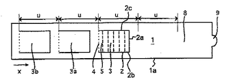
図1に示した重ね巻き付けラベルは材料層1を有しており、この材料層はその裏面で、少なくとも所々で感圧接着剤によってコーティングされている。材料層1の縁まで延びるL字形の型抜き部2によって長方形の薄片3が作り出されており、この薄片は折り目線4を介して残りの材料層1と繋がっている。薄片3は、材料層1からめくり上げることができ、または立たせることができ、その際に薄片は、材料層1との繋がりを維持している折り目線4の周りを回転する。薄片3は、複数の弱化線5によって細長片に区分されており、この細長片は単独でまたは複数一緒に切り離すことができ、これにより細長片を記録のために使用することができる。弱化線5は、この例ではミシン目型抜き部によって実現されている。弱化線の別の種類、例えばフィルム層の少なくとも部分的な裂け目またはその類似物も同様に可能である。
The overwrap label shown in FIG. 1 has a
L字形の型抜き部2は、第1の区間2aを有しており、この第1の区間はラベルの主延長方向xに対して横に、例えば垂直に走っている。図1に示した実施例では、L字形の型抜き部の第1の区間2aは、材料層1のうち一番下に示された左から右に延びるエッジ1aに対して横または垂直に走っている。L字形の型抜き部の第2の区間2bは、第1の区間2aに対して横に、例えば垂直に、およびこの実施例では材料層1の前述のエッジ1aに平行に走っている。折り目線4のほうは材料層1の前述のエッジ1aに対して横に、例えば垂直に走っており、したがってこの実施例ではL字形の型抜き部の第1の区間2aに平行に走っている。
The L-shaped die-
この例でミシン目型抜き部として形成された弱化線5の場合、それぞれの弱化線に沿って、型抜きされた区間と型抜きされない区間とが交互に入れ替わっている。L字形の型抜き部2は、この実施例ではL字形全体に沿って連続して型抜きされており、この型抜き部の場合、材料層1はL字形の全部の線2a、2bに沿って、折り目線4から始まり材料シート1のうち上に示した末端エッジ1bまで連続的かつ完全に切断されている。したがって長方形の薄片3は、L字形2の線に沿って材料層から外側に曲げることができ、その際、薄片は折り目線4の周りを旋回する。
In the case of the weakened
第2の薄片3aは、薄片3と類似したやり方で型抜きされている。ただし、長方形の薄片3aの縁であるL字形の型抜き部は、連続した型抜き部(薄片3の場合のような)の形ではなく、ミシン目型抜き部によって実施されている。薄片3aも、複数の弱化線5aによって細長片に区分されており、この細長片は単独でまたは複数一緒に切り離すことができ、これにより細長片を記録のために使用することができる。弱化線5は、同様にミシン目型抜き部またはその類似物によって実現されている。
The
材料層1の裏面では、薄片3aの領域内の感圧接着剤コーティングが、図示されていないフィルム片またはその他のカバー手段、例えば適切な紙によってカバーされており、これにより、弱化線5aによって定義された切り離し可能な細長片が永続的に、重ね巻き付けラベルが接着される容器と結合することを回避できる。
On the back side of the
重ね巻き付けラベルの第3の領域は封止部分8として用いられ、かつ末端側に把持フラップ9を備えている。
The third region of the overwrapping label is used as a sealing
重ね巻き付けラベルは、この例ではラベリングすべき容器の周長の3倍を少し超える長さを有している。領域3aと薄片3は、おおよそ容器周長uだけ変位されており、または間隔uだけ変位されている。その際uは容器6(図2)の断面の周長である。
The overwrap label has a length in this example that is slightly more than three times the circumference of the container to be labeled. The
材料層1はその片方の長手辺で、この材料層が薄片3および3aの領域内にそれぞれ拡張部10、10aを有し、両方の前述の薄片3および3aがいわばそれ以外の縁線からはみ出るように型抜きされている。
容器上に重ね巻き付けラベルを適用する際、両方の薄片3および3aが永続的に貼り合わさること、ならびに薄片3が封止部分8と貼り合わさることを防ぐため、裏面の接着剤コーティングを、領域3内および封止部分8の中心領域内ではブランクにする、またはカバーもしくは重ね刷りによって無効化する。ただし封止部分8のうち把持フラップ9がある縁領域は、裏面に有効な感圧接着剤を備えており、これにより重ね巻き付けラベルを、さらに下で説明するように封止することができる。
When applying the overwrap label on the container, the adhesive coating on the back side is applied to the
裏面の感圧接着剤をブランクにするかまたはカバーする代わりに、薄片3および3aの表面が、接着剤をはじくコーティングを備えることができ、これにより容器上に重ね巻き付けラベルを適用する際、両方の薄片3および3aが永続的に貼り合わさること、ならびに薄片3が封止部分8と貼り合わさることを防ぐことができる。
Instead of blanking or covering the pressure sensitive adhesive on the back side, the surface of the
図2は、斜視図において円筒形の容器6を示しており、この容器は、図1に示した重ね巻き付けラベルによってラベリングされており、その際、重ね巻き付けラベルは部分的に剥離している。容器6のラベリングは、材料層1のうち図1で左にある縁を容器6上に、材料層1の左縁が容器6の軸方向に平行に延びるように接着するやり方で行われる。ラベルを3回容器6の周りに巻き付け、その際、感圧接着剤でコーティングされた部分は固定的に容器6と結合する。薄片3aは、容器6のすぐ上に置かれている。薄片3は、薄片3aに対してほぼ周長距離uだけ、または周長距離uよりわずかに大きく変位されているので、薄片3は薄片3aの真上に置かれている。ただし上述の措置の故に、両方の薄片3および3aは相互に貼り付いていない。薄片3のすぐ上に封止部分8が置かれている。封止部分8と薄片3との間にも結合は存在せず、いずれにしても永続的な結合は存在しない。薄片3はL字形の型抜き線2によって切り離されており、かつ折り目線4を介してのみ材料層1の残りの部分と繋がっているので、この薄片は、材料層1からめくり上げることができる。L字形に型抜きすることで、長方形の薄片3が生じる。
FIG. 2 shows a cylindrical container 6 in a perspective view, which is labeled with the overwrap label shown in FIG. 1, with the overwrap label partially peeled off. The labeling of the container 6 is performed in such a manner that the left edge of the
長方形の薄片3またはL字形の型抜き部の代わりに、型抜き線が別の形を有することも可能であり、ただし型抜き線は少なくとも、折り目線4から材料シート1の縁1bまで走っていなければならない。円区間を、または別の丸みおよび/または角を有する軌跡を、上に提示した縁条件のもとで含む型抜き線も考えられるであろう。
Instead of
図2で認識できるように、重ね巻き付けラベルの一部分、つまり封止部分8は巻きを解かれている(開かれている)。上述の措置の故に、永続的な付着結合は、封止部分8と薄片3との間には存在しない。容器6に接している薄片3aと薄片3との間にも同様に接着結合は存在せず、したがって結果的に薄片3は固定されておらず、かつ細長片ごとに破り取ることができる。薄片3の1つまたは複数の細長片を破り取った後は、重ね巻き付けラベルを封止部分8で封止する。
As can be seen in FIG. 2, a portion of the overwrapping label, i.e. the sealing
図2で認識できるように、薄片3は材料層1の拡張部10の故にはみ出しており、したがって巻き付けられた(封止された)重ね巻き付けラベルの場合も、薄片3が完全にまたは部分的にまだ存在しているかどうかを認識することができる。薄片3aも拡張部10aの故に封止部分8の縁からはみ出ている。ただし拡張部10aは図面では見えておらず、なぜなら拡張部10aが、薄片3の拡張部10によって覆い隠されているからであり、これは薄片3がまだ完全に存在している間に限られる。
As can be seen in FIG. 2, the
図3は、本発明に基づく重ね巻き付けラベルの第2の実施例の平面図において示している。図1に示した実施形態とは違い図3に示した実施例は、全部で5つの薄片を有しており、この薄片のうちの1つ(薄片3d)は、ミシン目型抜き部によって型抜きされており、一方でそれ以外の薄片3、3a、3b、3cは、L字形の連続した型抜き部2によって材料層から切り離されている。図3の実施例に基づき明らかにされるべきことは、薄片の数が2つに制限されないということである。この重ね巻き付けラベルは6回の巻き付けによって容器に適用される。実際にはその際、容器の周長が材料層により、それぞれの巻き付けの際に材料層の厚さに応じて増加することに留意すべきである。その際、薄片の変位が容認され得るか、または重ね巻き付けラベルを、薄片の間隔が漸進的に実際の周長の増大に対応して増加するように形成することができる。したがって図面で示したサイズuは、定数として理解すべきではなく、実際の周長であり、この実際の周長は、実際の周長または容器の半径を基に、既に巻かれた層の厚さを加算して算出することができる。つまり複数の示したサイズuは、左から右へとわずかに増加しており、その際にこの増加は、その下で容器上に巻き付けられているラベルの層の数によって増えていく厚さから生じている。
FIG. 3 shows in plan view a second embodiment of a wrap-around label according to the invention. Unlike the embodiment shown in FIG. 1, the example shown in FIG. 3 has a total of five slices, and one of these slices (
図4は、本発明に基づく重ね巻き付けラベルの第3の実施例を示している。平面図において示したラベルは材料層1から成り、この材料層はその裏面で、感圧接着剤によってコーティングされている。大まかな輪郭がほぼU字形の型抜き部2により、長方形の薄片3が作り出されており、この薄片は、折り目線4を介して残りの材料シート1と繋がっている。薄片3は、材料層1の両方の長手縁にそれぞれ縁帯部が残るように材料層1で位置決めされている。薄片3は、複数の弱化線5によって細長片状の領域に区分されており、この領域は単独でまたは複数一緒に切り離すことができる。弱化線5は、この例ではミシン目型抜き部によって実現されている。弱化線の別の種類も同様に、図1に関連して述べたように可能である。
FIG. 4 shows a third embodiment of a wrap-around label according to the present invention. The label shown in the plan view consists of a
U字形は、2つの互いに平行またはほぼ平行に走る2つの区間2b、2cを有しており、これらの区間は末端で、この区間に対して横または垂直に走っている第1の区間2aを介して相互に繋がっている。U字形の全部の線2b、2a、2cに沿って、材料層1は完全に切断されている。U字形の第1の区間2aは、折り目線4に平行またはほぼ平行に延びている。区間2b、2cは、材料層1のうち長手延長方向xに走っている側縁に平行またはほぼ平行に延びている。
The U-shape has two
図4から明らかなように、2つのさらなる薄片3aおよび3bが企図されており、これらの薄片は、薄片3と同じ輪郭を有しているが、ただし薄片3とは違い弱化線によって区分されていない。薄片3aおよび3bは、全体的に、かつ永続的に、重ね巻き付けラベル内にあり続け、かつ一般的には使用説明書またはその類似物が印刷されている。これらの薄片は、裏面および表面に接着剤が着いておらず、表面にも裏面にも情報を印刷することができる。
As can be seen from FIG. 4, two
最後にこの重ね巻き付けラベルは封止部分8を有しており、この封止部分は、末端側に把持フラップ9を備えている。容器上に重ね巻き付けラベルを適用する際、封止部分8が薄片3と永続的に貼り合わさることを防ぐため、裏面の接着剤コーティングを、封止部分8の中心領域内ではブランクにする、またはカバーもしくは重ね刷りによって無効化する。ただし封止部分8のうち把持フラップ9がある縁領域は、裏面に有効な感圧接着剤を備えており、これにより重ね巻き付けラベルを、さらに下で説明するように封止することができる。
Finally, the wrap-around label has a sealing
封止部分8の裏面で接着剤をカバーする代わりに、薄片3の表面が、接着剤をはじくコーティング、例えばシリコーン被覆を備えることができる。
Instead of covering the adhesive with the back side of the sealing
重ね巻き付けラベルは、この例ではラベリングすべき容器の周長の4倍を少し超える長さを有している。薄片3、3a、および3bは、それぞれおおよそ容器周長だけ相対的に変位されている。
The overwrap label has a length in this example that is slightly more than four times the circumference of the container to be labeled. The
図5は、平面図において円筒形の容器6を示しており、この容器は、図4に示した重ね巻き付けラベルによってラベリングされている。容器6のラベリングは、材料層1のうち図4で左にある縁を容器6上に、材料層1の左縁が容器の軸方向に延びるように接着するやり方で行われる。ラベルを4回容器6の周りに巻き付け、その際、感圧接着剤でコーティングされた部分は固定的に容器6と結合する。薄片3bは、容器6のすぐ上に置かれている。薄片3aは、薄片3bに対して周長距離uだけ変位されているので、薄片3aは薄片3bの真上に置かれている。同じように薄片3が薄片3aの上に置かれている。薄片3aおよび3bは、上で説明したようにその裏面にも表面にも接着剤が着いていないので、これらの薄片は相互に貼り付いていない。薄片3のすぐ上に封止部分8が置かれている。封止部分8と薄片3との間にも接着結合は存在せず、いずれにしても永続的な接着結合は存在しない。これらの薄片は大まかな輪郭がU字形の型抜き部2によって材料層1から分離されており、かつ折り目線4に沿ってのみ材料層1との繋がりを維持しているので、薄片3、3a、3bは、材料層1からめくり上げることができる。
FIG. 5 shows a cylindrical container 6 in plan view, which is labeled with the overwrap label shown in FIG. The labeling of the container 6 is performed in such a manner that the edge of the
図5は、重ね巻き付けラベルを開いた状態で示しており、つまり封止部分8が、把持フラップ9を把持して剥離することによって持ち上げられており、かつ薄片3、3a、3bがこれによって広がっている。認識できるように小冊子またはブックレットができており、この小冊子またはブックレットの場合、2つの薄片3aおよび3bで前面にも後面にも、つまり全部で4面に情報を表示することができる。第3の薄片3は、記録のために破り取る細長片を用意するために用いられる。情報を読んだ後および/または細長片を取った後は、この「小冊子」を再び封止することができ、なぜなら既に言及したように把持フラップ9の付近の封止部分の縁領域が、裏面に感圧接着剤を備えているからである。
FIG. 5 shows the wrap-wrap label open, i.e. the sealing
上記の図4の実施例の変形形態では、より多くの薄片または全ての薄片が、薄片3のように弱化線を備えてもよいであろうし、または全ての薄片を、薄片3aおよび3bのような純粋な情報薄片として実施してもよいであろう。全部で3枚より多いまたは少ない薄片を企図してもよいであろう。
In the variant of the embodiment of FIG. 4 above, more or all slices may be provided with weakening lines as in
図6は、本発明に基づく重ね巻き付けラベルの第4の実施例の平面図において示している。平面図において示したラベルは材料層1から成り、この材料層はその裏面で、感圧接着剤によってコーティングされている。4つの、大まかな輪郭がほぼU字形の型抜き部2により、4つの長方形の薄片3、3a、3b、および3cが作り出されており、これらの薄片は、それぞれ折り目線4を介して残りの材料シート1と繋がっている。薄片3、3a、3b、および3cは、材料層1の両方の長手縁にそれぞれ縁帯部が残るように材料層1で位置決めされている。
FIG. 6 shows a plan view of a fourth embodiment of a wrap-around label according to the invention. The label shown in the plan view consists of a
薄片3、3a、3b、および3cは、全体的に、かつ永続的に、重ね巻き付けラベル内にあり続け、かつ一般的には使用説明書またはその類似物が印刷されている。これらの薄片は、裏面および表面に接着剤が着いておらず、表面にも裏面にも情報を印刷することができる。
The
最後にこの重ね巻き付けラベルは封止部分8を有しており、この封止部分は、末端側に把持フラップ9を備えている。容器上に重ね巻き付けラベルを適用する際、封止部分8が薄片3および3aと永続的に貼り合わさることを防ぐため、裏面の接着剤コーティングを、封止部分8の中心領域内ではブランクにする、またはカバーもしくは重ね刷りによって無効化する。ただし封止部分8のうち把持フラップ9がある縁領域は、裏面に有効な感圧接着剤を備えており、これにより重ね巻き付けラベルを封止することができる。
Finally, the wrap-around label has a sealing
封止部分8の裏面で接着剤をカバーする代わりに、薄片3および3aの表面が、接着剤をはじくコーティングを備えることができる。
Instead of covering the adhesive with the back side of the sealing
重ね巻き付けラベルは、この例ではラベリングすべき容器の周長の3倍を少し超える長さを有している。上述の実施例とは違い薄片3、3a、3b、および3cは、それぞれおおよそ半分の容器周長u/2だけ相対的に変位されている。
The overwrap label has a length in this example that is slightly more than three times the circumference of the container to be labeled. Unlike the embodiment described above, the
図7は、平面図において円筒形の容器6を示しており、この容器は、図6に示した重ね巻き付けラベルによってラベリングされている。容器6のラベリングは、材料層1のうち図6で左にある縁を容器6上に、材料層1の左縁が容器の軸方向に延びるように接着するやり方で行われる。ラベルを3回容器6の周りに巻き付け、その際、感圧接着剤でコーティングされた部分は固定的に容器6と結合する。薄片3cは、容器6のすぐ上に置かれている。薄片3bは、薄片3cに対して半分の周長距離u/2だけ変位されているので、薄片3bは薄片3cの対極に置かれている。薄片3aは薄片3cの上に置かれており、なぜなら薄片3aが薄片3cに対して完全な周長(u/2+u/2)だけ変位されているからである。薄片3は薄片3bの上に置かれており、なぜなら薄片3が薄片3bに対して完全な周長だけ変位されているからである。最後に封止部分が薄片3および3aの上に置かれている。封止部分は完全な周長の長さを有しているので、この封止部分は、閉じた状態では全ての薄片3、3a、3b、3cを覆い隠している。
FIG. 7 shows a cylindrical container 6 in plan view, which is labeled with the lap wrap label shown in FIG. The labeling of the container 6 is performed in such a manner that the edge of the
薄片3、3a、3b、3cは、上で説明したようにその裏面でも表面でも接着剤が着いていないので、これらの薄片は相互に貼り付いていない。薄片3および薄片3aのすぐ上に封止部分8が置かれている。封止部分8と薄片3、3aとの間にも接着結合は存在せず、いずれにしても永続的な接着結合は存在しない。これらの薄片は大まかな輪郭がU字形の型抜き部2によって材料層1から分離されており、かつ折り目線4に沿ってのみ材料層1との繋がりを維持しているので、薄片3、3a、3b、3cは、材料層1からめくり上げることができる。
As described above, the
図7は、重ね巻き付けラベルを開いた状態で示しており、つまり封止部分8が、把持フラップ9をつかんで引っ張ることによって持ち上げられており、かつ薄片3、3a、3b、3cがこれによって広がっている。認識できるように、u/2での薄片の特殊な変位により、2つの小冊子ができている。情報を読んだ後および/または細長片を取った後は、この「小冊子」を再び封止することができ、なぜなら既に言及したように把持フラップ9の付近の封止部分の縁領域が、裏面に感圧接着剤を塗付しているからである。
FIG. 7 shows the wrap-wrap label open, i.e. the sealing
図8は、本発明に基づく重ね巻き付けラベルの第5の実施例の平面図において示している。平面図において示したラベルは材料層1から成り、この材料層はその裏面で、感圧接着剤によってコーティングされている。4つの、大まかな輪郭がほぼU字形の型抜き部2により、4つの長方形の薄片3、3a、3b、および3cが作り出されており、これらの薄片は、それぞれ折り目線4を介して残りの材料シート1と繋がっている。薄片3、3a、3b、および3cは、材料層1の両方の長手縁にそれぞれ縁帯部が残るように材料層1で位置決めされている。
FIG. 8 shows a plan view of a fifth embodiment of a wrap-around label according to the invention. The label shown in the plan view consists of a
薄片3、3a、3b、および3cは、全体的に、かつ永続的に、重ね巻き付けラベル内にあり続け、かつ一般的には使用説明書またはその類似物が印刷されている。これらの薄片は、裏面および表面に接着剤が着いておらず、表面にも裏面にも情報を印刷することができる。
The
最後にこの重ね巻き付けラベルは封止部分8を有しており、この封止部分は、末端側に把持フラップ9を備えている。容器上に重ね巻き付けラベルを適用する際、封止部分8が薄片3および3aと永続的に貼り合わさることを防ぐため、裏面の接着剤コーティングを、封止部分8の中心領域内ではブランクにする、またはカバーもしくは重ね刷りによって無効化する。ただし封止部分8のうち把持フラップ9がある縁領域は、裏面に有効な感圧接着剤を塗付しており、これにより重ね巻き付けラベルを封止することができる。
Finally, the wrap-around label has a sealing
封止部分8の裏面で接着剤をカバーする代わりに、薄片3および3aの表面が、接着剤をはじくコーティングを備えることができる。
Instead of covering the adhesive with the back side of the sealing
重ね巻き付けラベルは、この例ではラベリングすべき容器の周長の3倍を少し超える長さを有している。薄片3、3a、3b、および3cは、それぞれおおよそ半分の容器周長u/2だけ相対的に変位されている。薄片3、3a、3b、および3cは、折り目線4から測って、重ね巻き付けラベルの長手方向において容器の周長の4分の1弱の長さを有している。
The overwrap label has a length in this example that is slightly more than three times the circumference of the container to be labeled. The
図9は、平面図において容器6を示しており、この容器は、図8に示した重ね巻き付けラベルによってラベリングされている。容器6の断面は、基本形においては正方形で、それぞれ丸みのある角を備えている。代替案として断面は長方形で、丸みのある角を備えてもよいであろうし、または基本的に丸みのある角でなくてもよいであろう。容器6のラベリングは、材料層1のうち図8で下にある縁を容器6上に、材料層1の下縁が容器の軸方向に延びるように接着するやり方で行われる。ラベルを容器6の周りに3回巻き付け、その際、感圧接着剤でコーティングされた部分は固定的に容器6と結合する。薄片3cは、容器6のすぐ上に置かれている。薄片3bは、薄片3cに対して半分の周長距離u/2だけ変位されているので、薄片3bは薄片3cの対極に置かれている。薄片3aは薄片3cの上に置かれており、なぜなら薄片3aが薄片3cに対して完全な周長(u/2+u/2)だけ変位されているからである。薄片3は薄片3bの上に置かれており、なぜなら薄片3が薄片3bに対して完全な周長だけ変位されているからである。最後に封止部分が薄片3および3aの上に置かれている。封止部分は完全な周長の長さを有しているので、この封止部分は、閉じた状態では全ての薄片3、3a、3b、3cを覆い隠している。
FIG. 9 shows the container 6 in plan view, which is labeled with the wrap-around label shown in FIG. The cross section of the container 6 is square in the basic shape, and each has a rounded corner. As an alternative, the cross-section may be rectangular and may have rounded corners, or essentially no rounded corners. The labeling of the container 6 is performed in such a way that the lower edge of the
薄片3、3a、3b、3cは、上で説明したようにその裏面でも表面でも接着剤が着いていないので、これらの薄片は相互に貼り付いていない。薄片3および薄片3aのすぐ上に封止部分8が置かれている。封止部分8と薄片3、3aとの間にも接着結合は存在せず、いずれにしても永続的な接着結合は存在しない。これらの薄片は大まかな輪郭がU字形の型抜き部2によって材料層1から分離されており、かつ折り目線4に沿ってのみ材料層1との繋がりを維持しているので、薄片3、3a、3b、3cは、材料層1からめくり上げることができる。図9は、平面図において、断面が正方形の、図8からの重ね巻き付けラベルによってラベリングされた容器を示しており、その際、重ね巻き付けラベルは部分的に剥離している。
As described above, the
図9は、重ね巻き付けラベルを開いた状態で示しており、つまり封止部分8が、把持フラップ9をつかんで引っ張ることによって持ち上げられており、かつ薄片3、3a、3b、3cがこれによって広がっている。認識できるように、u/2での薄片の特殊な変位により、2つの小冊子ができている。薄片3、3a、3b、3cは、周長方向において全周長の4分の1弱にわたって延びているので、個々の薄片は正方形の容器の平らな側壁上に置かれている。情報を読んだ後は、この「小冊子」を再び封止することができ、なぜなら既に言及したように把持フラップ9の付近の封止部分の縁領域が、裏面に感圧接着剤を備えているからである。
FIG. 9 shows the wrap-wrap label open, i.e. the sealing
要約すると、本発明は重ね巻き付けラベルを記載しており、この重ね巻き付けラベルは、多数の翼状部分および/または証明部分を用意することができる。翼状部分は、片面または両面に情報を備えることができる。証明部分も同様に情報を備えており、かつ取り外し可能に実施されている。入れ物を提案したラベルで何層にも巻き付けることにより、多数の翼状部分および/または証明部分を小さな入れ物の表に収め得る構造が生じる。さらに、提案したラベルを備えた容器を記載する。このようにラベリングされた容器は大量の情報を備えることができる。 In summary, the present invention describes a wrap-around label, which can provide multiple wings and / or proof portions. The winged portion can comprise information on one or both sides. The certification part is likewise equipped with information and is detachable. By wrapping the container in layers with the proposed label, a structure is created that allows a large number of wings and / or proof parts to fit in a small container table. In addition, a container with the proposed label is described. Containers labeled in this way can have a large amount of information.
1 材料層
2 型抜き部
3、3a、3b、3c、3d 薄片
4 折り目線
5 弱化線
6、7 容器
8 封止部分
9 把持フラップ
10、10a 拡張部
1 Material layer
2 Die-cut part
3, 3a, 3b, 3c, 3d flakes
4 Crease line
5 Weak line
6, 7 containers
8 Sealing part
9 Grip flap
10, 10a extension
Claims (17)
前記材料層(1)が、少なくとも1つの型抜きされた薄片(3、3a、3b、3c、3d)を有しており、前記薄片が、前記材料層(1)からめくり上げられることを可能にしていることを特徴とする重ね巻き付けラベル。 A wrap-wrap label for labeling containers (6, 7), having at least one material layer (1), said material layer being at least partly an adhesive back surface and a surface on which information is marked In a wrap-around label having
The material layer (1) has at least one stamped flake (3, 3a, 3b, 3c, 3d), allowing the flake to be rolled up from the material layer (1) A wrap-around label characterized by
前記材料層(1)が、少なくとも1つの型抜きされた薄片(3、3a、3b、3c、3d)を有しており、前記薄片が、前記材料層(1)からめくり上げられることを可能にしていることを特徴とする容器。 A cylindrical or prismatic container (6, 7) labeled with an overwrapping label, wherein the overwrapping label has at least one material layer (1), the material layer at least in some places. In a container having a wearable back surface and a surface on which information is written,
The material layer (1) has at least one stamped flake (3, 3a, 3b, 3c, 3d), allowing the flake to be rolled up from the material layer (1) A container characterized by being made.
Applications Claiming Priority (1)
| Application Number | Priority Date | Filing Date | Title |
|---|---|---|---|
| DE102009001206.0A DE102009001206B4 (en) | 2009-02-26 | 2009-02-26 | Oval label and container with such label |
Publications (1)
| Publication Number | Publication Date |
|---|---|
| JP2010198019A true JP2010198019A (en) | 2010-09-09 |
Family
ID=42197703
Family Applications (1)
| Application Number | Title | Priority Date | Filing Date |
|---|---|---|---|
| JP2010040244A Pending JP2010198019A (en) | 2009-02-26 | 2010-02-25 | Surrounding label and container with the label |
Country Status (4)
| Country | Link |
|---|---|
| US (1) | US20100215876A1 (en) |
| EP (1) | EP2224417A1 (en) |
| JP (1) | JP2010198019A (en) |
| DE (1) | DE102009001206B4 (en) |
Cited By (1)
| Publication number | Priority date | Publication date | Assignee | Title |
|---|---|---|---|---|
| JP2011164313A (en) * | 2010-02-09 | 2011-08-25 | Kondo Insatsu Seihansho:Kk | Multiple label |
Families Citing this family (4)
| Publication number | Priority date | Publication date | Assignee | Title |
|---|---|---|---|---|
| DE102009030841A1 (en) * | 2009-06-26 | 2010-12-30 | Schreiner Group Gmbh & Co. Kg | Multi-layer label for adhering to a curved, in particular cylindrical surface of an article |
| DE202009011815U1 (en) * | 2009-09-01 | 2009-12-31 | Schreiner Group Gmbh & Co. Kg | Multi-layer label |
| DE102010013040B4 (en) | 2010-03-26 | 2014-08-21 | Schreiner Group Gmbh & Co. Kg | Label for adhering to a container for a medicament fluid and container |
| US11738901B1 (en) | 2021-07-09 | 2023-08-29 | Mehdi Pishahang | Retractable scrollable labels for applying to an object |
Family Cites Families (10)
| Publication number | Priority date | Publication date | Assignee | Title |
|---|---|---|---|---|
| US4312523A (en) | 1979-10-29 | 1982-01-26 | Paco Packaging Incorporated | Label for container having pharmaceutical product therein |
| IE893824A1 (en) * | 1989-11-30 | 1991-06-05 | Creative Europ Ltd | A Label |
| ATE106154T1 (en) * | 1990-06-23 | 1994-06-15 | Schreiner Etiketten | SELF-ADHESIVE LABEL FOR LABELING CYLINDRICAL OR PRISMATIC CONTAINERS. |
| US5881597A (en) | 1996-08-22 | 1999-03-16 | Brooks; Ruth | Consumption indicator label apparatus, and methods of using same |
| DE19650720C2 (en) * | 1996-12-06 | 1999-04-29 | Tovenca Ag | Self-adhesive label |
| US6193279B1 (en) | 1997-10-17 | 2001-02-27 | Schreiner Etiketten Und Selbstiebetechnik Gmbh & Co. | Label for labelling of preferably cylindrical containers |
| JP2004184552A (en) | 2002-11-29 | 2004-07-02 | Koopakku International Kk | Printed labels |
| US7601410B2 (en) | 2004-08-09 | 2009-10-13 | Wisconsin Label Corporation | Multi-ply wrap label |
| AU2004324158A1 (en) * | 2004-10-13 | 2006-04-27 | Donald S. Farnsworth | Re-attachable container identifiers |
| DE202007007184U1 (en) * | 2007-05-19 | 2007-09-27 | Faubel & Co. Nachfolger Gmbh | Wrap label for attachment to a container |
-
2009
- 2009-02-26 DE DE102009001206.0A patent/DE102009001206B4/en not_active Expired - Fee Related
-
2010
- 2010-02-22 EP EP10154269A patent/EP2224417A1/en not_active Withdrawn
- 2010-02-25 JP JP2010040244A patent/JP2010198019A/en active Pending
- 2010-02-25 US US12/660,359 patent/US20100215876A1/en not_active Abandoned
Cited By (1)
| Publication number | Priority date | Publication date | Assignee | Title |
|---|---|---|---|---|
| JP2011164313A (en) * | 2010-02-09 | 2011-08-25 | Kondo Insatsu Seihansho:Kk | Multiple label |
Also Published As
| Publication number | Publication date |
|---|---|
| DE102009001206A1 (en) | 2010-09-02 |
| EP2224417A1 (en) | 2010-09-01 |
| DE102009001206B4 (en) | 2019-01-10 |
| US20100215876A1 (en) | 2010-08-26 |
Similar Documents
| Publication | Publication Date | Title |
|---|---|---|
| US6613410B1 (en) | Extended wrap label | |
| US8042293B1 (en) | Article encircling band with removable coupon or ticket | |
| US20020086127A1 (en) | Label sheet construction and method | |
| EP2380158B1 (en) | Sticker sheets and wrapping material | |
| US20090249751A1 (en) | Wrapping paper | |
| JP2010198019A (en) | Surrounding label and container with the label | |
| US20120000970A1 (en) | Gift wrap with tape | |
| US6451397B1 (en) | Pouch label | |
| JP4436636B2 (en) | Multilayer label, receptacle provided with multilayer label, and method of manufacturing multilayer label | |
| EP4030410A1 (en) | Multilayer label | |
| JP4606241B2 (en) | Storage label and storage label continuum | |
| JP7298990B2 (en) | packaging sheet | |
| WO2008142434A2 (en) | Folded leaflet and label for packaging | |
| JP2007112475A (en) | Wrap film storage carton | |
| JP6629655B2 (en) | Campaign label and label continuum | |
| US20120211550A1 (en) | Wrapper | |
| JP6819137B2 (en) | Delivery slip | |
| US10294002B2 (en) | Easy open package | |
| CN210142465U (en) | Instruction book label sticker with anti-counterfeiting function | |
| JP2005008778A (en) | Easy-release adhesive tape | |
| JP4319876B2 (en) | Containers with adhesive bags with adhesive tape attached | |
| CA1304937C (en) | Multiple wrap label | |
| JP2006241178A (en) | Adhesive tape | |
| JP6853108B2 (en) | Invoice | |
| JP2006103732A (en) | Label feeding strip and method for manufacturing the same |