JP2010147249A - Optical characteristic measuring method, exposure condition determining method, exposure method, and device manufacturing method - Google Patents
Optical characteristic measuring method, exposure condition determining method, exposure method, and device manufacturing method Download PDFInfo
- Publication number
- JP2010147249A JP2010147249A JP2008322889A JP2008322889A JP2010147249A JP 2010147249 A JP2010147249 A JP 2010147249A JP 2008322889 A JP2008322889 A JP 2008322889A JP 2008322889 A JP2008322889 A JP 2008322889A JP 2010147249 A JP2010147249 A JP 2010147249A
- Authority
- JP
- Japan
- Prior art keywords
- pattern
- optical system
- projection optical
- exposure
- image
- Prior art date
- Legal status (The legal status is an assumption and is not a legal conclusion. Google has not performed a legal analysis and makes no representation as to the accuracy of the status listed.)
- Pending
Links
Images


Landscapes
- Testing Of Optical Devices Or Fibers (AREA)
- Exposure And Positioning Against Photoresist Photosensitive Materials (AREA)
- Exposure Of Semiconductors, Excluding Electron Or Ion Beam Exposure (AREA)
Abstract
【課題】投影光学系の光学特性を精度良く計測する。
【解決手段】ステップ417において、ステップ406の露光処理によってウエハ上の複数の領域に形成された計測用パターンの像の形成状態の検出結果に基づいて、投影光学系の光学特性計測のための前記パターンの露光の最適ドーズ量が仮に決定される。そして、ステップ424で、目標ドーズ量を、上記最適ドーズ量を中心としてより細かいステップピッチで複数段階で変化させて、ステップ406と同様の露光処理により前記パターンが投影光学系を介してウエハ上の複数の領域に転写される。従って、投影光学系の光学特性計測のための露光条件の一部が微調整される。そして、その微調整された露光条件の下での露光によってウエハ上の各領域に形成された前記パターンの像の形成状態の検出結果に基づいて、投影光学系の光学特性が求められる(ステップ436、438)。
【選択図】 図4
An optical characteristic of a projection optical system is accurately measured.
In step 417, based on the detection result of the formation state of the image of the measurement pattern formed in a plurality of regions on the wafer by the exposure processing in step 406, the optical property measurement for measuring the optical characteristics of the projection optical system is performed. An optimal dose amount for pattern exposure is temporarily determined. In step 424, the target dose amount is changed in a plurality of stages at a finer step pitch with the optimum dose amount as the center, and the pattern is exposed on the wafer via the projection optical system by the exposure process similar to step 406. Transferred to multiple areas. Accordingly, a part of the exposure condition for measuring the optical characteristics of the projection optical system is finely adjusted. Then, the optical characteristics of the projection optical system are obtained based on the detection result of the image formation state of the pattern formed in each region on the wafer by the exposure under the finely adjusted exposure condition (step 436). 438).
[Selection] Figure 4
Description
本発明は、光学特性計測方法、露光条件決定方法、露光方法、及びデバイス製造方法に係り、更に詳しくは、投影光学系の光学特性を計測する光学特性計測方法、投影光学系の光学特性を計測するための試料を作成する際の露光条件を決定する露光条件決定方法、前記光学特性計測方法を利用する露光方法、及び該露光方法を用いるデバイス製造方法に関する。 The present invention relates to an optical property measurement method, an exposure condition determination method, an exposure method, and a device manufacturing method. More specifically, the present invention relates to an optical property measurement method for measuring optical properties of a projection optical system, and measures the optical properties of a projection optical system. The present invention relates to an exposure condition determination method for determining an exposure condition for preparing a sample to be performed, an exposure method using the optical characteristic measurement method, and a device manufacturing method using the exposure method.
半導体素子(集積回路)等は年々高集積化しており、これに伴い半導体素子等の製造装置であるステッパなどの投影露光装置には、一層の高解像力が要求されるようになってきた。また、被露光物体上に既に形成されているパターンに対する次層以後のパターンの重ね合わせ精度を向上させることも重要である。このためには、投影光学系の光学特性を向上させることが必要であり、その前提として投影光学系の光学特性(結像特性を含む)を正確に計測し、評価することが重要となっている。 Semiconductor elements (integrated circuits) and the like have been highly integrated year by year, and accordingly, a projection apparatus such as a stepper, which is a manufacturing apparatus for semiconductor elements, has been required to have higher resolution. It is also important to improve the overlay accuracy of the pattern after the next layer with respect to the pattern already formed on the object to be exposed. For this purpose, it is necessary to improve the optical characteristics of the projection optical system, and as a premise, it is important to accurately measure and evaluate the optical characteristics (including imaging characteristics) of the projection optical system. Yes.
投影光学系の光学特性、例えばパターンの像面の正確な計測は、投影光学系の視野内の各評価点(計測点)における最良フォーカス位置を正確に計測できることが前提となる。 Accurate measurement of the optical characteristics of the projection optical system, for example, the image plane of the pattern, is based on the premise that the best focus position at each evaluation point (measurement point) within the field of view of the projection optical system can be accurately measured.
従来の投影光学系の最良フォーカス位置の計測方法としては、いわゆるCD/フォーカス法が代表的に知られている。この方法では、所定のレチクルパターン(例えば、ラインアンドスペースパターン等)をテストパターンとして、このテストパターンを、投影光学系の光軸方向に関する複数の位置でテスト用ウエハに転写する。そして、そのテスト用ウエハを現像して得られるレジスト像(転写されたパターンの像)の線幅値を、走査型電子顕微鏡(SEM)等を用いて計測し、その線幅値と投影光学系の光軸方向に関するウエハ位置(以下、適宜「フォーカス位置」ともいう)との関係に基づいて、最良フォーカス位置を算出する。 A so-called CD / focus method is typically known as a method for measuring the best focus position of a conventional projection optical system. In this method, a predetermined reticle pattern (for example, a line and space pattern) is used as a test pattern, and the test pattern is transferred to a test wafer at a plurality of positions in the optical axis direction of the projection optical system. Then, the line width value of the resist image (transferred pattern image) obtained by developing the test wafer is measured using a scanning electron microscope (SEM) or the like, and the line width value and the projection optical system The best focus position is calculated based on the relationship with the wafer position in the optical axis direction (hereinafter also referred to as “focus position” where appropriate).
しかし、上述したCD/フォーカス法では、例えばレジスト像の線幅値をSEMで計測するために、SEMのフォーカス合わせを厳密に行う必要があり、1点当たりの計測時間が非常に長く、多数点での計測をするためには数時間から数十時間が必要とされていた。このため、計測結果が得られるまでのスループットが大幅に低下してしまう。これに加え、測定誤差や測定結果の再現性についても、より高いレベルが要求されるようになり、従来の計測方法ではその対応が困難となってきた。 However, in the above-mentioned CD / focus method, for example, in order to measure the line width value of a resist image with an SEM, it is necessary to strictly focus the SEM, and the measurement time per point is very long. It took several hours to several tens of hours to make measurements at the time. For this reason, the throughput until the measurement result is obtained is greatly reduced. In addition to this, higher levels of measurement error and reproducibility of measurement results are required, and it has become difficult to cope with the conventional measurement methods.
この他、特許文献1などに開示される、複数のフォーカス位置で、くさび形マークのレジスト像をウエハ上に形成し、アライメント系などのマーク検出系を用いてレジスト像の長手方向の長さ(フォーカス位置の違いによるレジスト像の線幅値の変化を増幅させたもの)を計測し、この計測結果を用いる、いわゆるSMPフォーカス計測法も知られている。しかし、このSMPフォーカス計測法では、通常、計測を単色光で行うために、レジスト像の形状の違いにより干渉の影響が異なり、それが計測誤差(寸法オフセット)につながるとともに、現状の画像取り込み機器(CCDカメラ等)の分解能では未だ十分ではない。また、テストパターンが大きいために、評価点の数を増加させることが困難であった。
In addition, a resist image of a wedge-shaped mark is formed on a wafer at a plurality of focus positions as disclosed in
上述した従来の各計測法の不都合を改善する方法として、発明者は、分解能の低い計測系、例えば露光装置の結像式アライメントセンサ等の計測装置を用いて、光学系の光学特性を高スループットで計測することが可能な計測方法を提案した(例えば、特許文献2参照)。 As a method for improving the disadvantages of the conventional measurement methods described above, the inventor has used a measurement system with a low resolution, for example, a measurement apparatus such as an imaging alignment sensor of an exposure apparatus, to improve the optical characteristics of the optical system with a high throughput. Has proposed a measurement method that can be measured by (see, for example, Patent Document 2).
特許文献2に記載の計測方法によると、客観的かつ定量的な像のコントラスト、回折光などの反射光の光量などを用いた検出結果に基づいて光学特性が求められるために、従来の方法と比較して光学特性を精度及び再現性良く計測することができる。また、評価点の数を増加させることができるとともに、各評価点間の間隔を狭くすることができ、結果的に光学特性計測の測定精度を向上させることが可能となる。
According to the measurement method described in
しかるに、最近では、トータルオーバレイ誤差の許容値が数nm程度であり、これを実現するためには、投影光学系の光学特性を計測するための計測方法として、上記のCD/フォーカス法、SMPフォーカス計測法、及び特許文献2に記載の計測方法のいずれを採用する場合でも、計測パターンの露光条件、例えばウエハ上に与えられる単位面積当たりのエネルギ線量(ドーズ量)などをより一層精度良く設定する必要が生じている。例えばドーズ量は、ウエハ上に転写、形成される計測パターンの像の形成状態に大きく影響を与えるからである。
本発明は、上述の事情の下でなされたものであり、第1の観点からすると、第1面上のパターンの像を第2面上に投影する投影光学系の光学特性を計測する光学特性計測方法であって、前記投影光学系の光軸方向に関する前記物体の位置、及び前記物体上に照射されるエネルギビームのエネルギ量の設定値を含む複数の露光条件の一部を所定の第1範囲内で段階的に変えつつ、前記第1面上に配置された計測用パターンを前記投影光学系を介して該投影光学系の第2面側に配置された前記物体上の複数の領域に順次転写する第1工程と;前記物体上の複数の領域における前記計測用パターンの像の形成状態を検出し、その検出結果に基づいて、前記投影光学系の光学特性計測のための前記一部の露光条件の少なくとも一部を仮に決定する第2工程と;前記少なくとも一部の露光条件を、前記仮に決定された露光条件を中心として前記第1範囲より狭い第2範囲内で複数段階で変化させ、複数段階の異なる露光条件のそれぞれの下で、前記第1面上に配置された前記計測用パターンを前記投影光学系を介して該投影光学系の第2面側に配置された前記物体上の複数の領域に順次転写する第3工程と;前記物体上の複数の領域における前記計測用パターンの像の形成状態を検出し、その検出結果に基づいて、前記投影光学系の光学特性を求める第4工程と;を含む第1の光学特性計測方法である。 The present invention has been made under the circumstances described above. From the first viewpoint, the optical characteristic for measuring the optical characteristic of the projection optical system that projects the image of the pattern on the first surface onto the second surface. In the measurement method, a part of a plurality of exposure conditions including a position of the object with respect to an optical axis direction of the projection optical system and a setting value of an energy amount of an energy beam irradiated on the object are set to a predetermined first. The measurement pattern arranged on the first surface is changed to a plurality of regions on the object arranged on the second surface side of the projection optical system via the projection optical system while changing stepwise within the range. A first step of sequentially transferring; and detecting the formation state of the image of the measurement pattern in a plurality of regions on the object, and based on the detection result, the part for measuring optical characteristics of the projection optical system A second that temporarily determines at least a part of the exposure condition And changing the at least some of the exposure conditions in a plurality of stages within a second range narrower than the first range centered on the provisionally determined exposure conditions, and under each of a plurality of different exposure conditions. A third step of sequentially transferring the measurement pattern arranged on the first surface to a plurality of regions on the object arranged on the second surface side of the projection optical system via the projection optical system; A fourth step of detecting a formation state of the image of the measurement pattern in a plurality of regions on the object and obtaining an optical characteristic of the projection optical system based on the detection result; This is a measurement method.
これによれば、第1工程の露光によって物体上の複数の領域に形成された計測用パターンの像の形成状態の検出結果に基づいて、投影光学系の光学特性計測のための前記一部の露光条件の少なくとも一部が仮に決定され(第2工程)、前記少なくとも一部の露光条件を、仮に決定された露光条件を中心として第1範囲より狭い第2範囲内で複数段階で変化させて、第1工程と同様の露光により計測用パターンを投影光学系を介して物体上の複数の領域に順次転写される(第3工程)。従って、投影光学系の光学特性計測のための露光条件の一部が微調整され、その微調整された露光条件の下で行われた露光によって物体上の複数の領域に形成された計測用パターンの像の形成状態の検出結果に基づいて、投影光学系の光学特性が求められる(第4工程)。従って、投影光学系の光学特性を精度良く求めることが可能になる。 According to this, based on the detection result of the formation state of the image of the measurement pattern formed in the plurality of regions on the object by the exposure in the first step, the part for measuring the optical characteristics of the projection optical system At least a part of the exposure condition is provisionally determined (second step), and the at least part of the exposure condition is changed in a plurality of steps within a second range narrower than the first range centering on the provisionally determined exposure condition. The measurement pattern is sequentially transferred to a plurality of regions on the object via the projection optical system by exposure similar to the first step (third step). Accordingly, a part of the exposure conditions for measuring the optical characteristics of the projection optical system is finely adjusted, and the measurement pattern formed in a plurality of areas on the object by the exposure performed under the finely adjusted exposure conditions Based on the detection result of the image formation state, the optical characteristics of the projection optical system are obtained (fourth step). Accordingly, the optical characteristics of the projection optical system can be obtained with high accuracy.
本発明は、第2の観点からすると、第1面上のパターンの像を第2面上に投影する投影光学系の光学特性を計測するための露光条件を決定する露光条件決定方法であって、前記投影光学系の光軸方向に関する前記物体の位置、及び前記物体上に照射されるエネルギビームのエネルギ量の設定値を含む複数の露光条件の一部を段階的に変更しつつ、前記第1面上に配置された第1パターンを前記投影光学系を介して該投影光学系の第2面側に配置された物体上の異なる複数の領域に順次転写する第1工程と;同一の露光条件を維持して、前記第1パターンの像に重ね合わせて第2パターンを前記投影光学系を介して転写することで、前記第1パターンの像が形成された前記物体上の複数の領域それぞれの一部を前記投影光学系を介して露光する第2工程と;前記第2工程の処理の後に前記物体上の複数の領域に形成されたパターンの像の形成状態を検出し、その検出結果に基づいて、前記第1パターンの露光条件を決定する第3工程と;前記決定された露光条件に従って、前記第1パターンを前記投影光学系を介して前記物体上の異なる複数の領域にそれぞれ転写する第4工程と;露光条件を変更しつつ、前記第1パターン像に重ね合わせて第2パターンを前記投影光学系を介して転写することで、前記第1パターンの像が形成された前記物体上の複数の領域それぞれの一部を前記投影光学系を介して露光する第5工程と;前記第5工程の処理の後に前記物体上の複数の領域に形成されたパターンの像の形成状態を検出し、その検出結果に基づいて、前記第2パターンの露光条件を決定する第6工程と;を含む露光条件決定方法である。
According to a second aspect of the present invention, there is provided an exposure condition determination method for determining an exposure condition for measuring an optical characteristic of a projection optical system that projects a pattern image on a first surface onto a second surface. , While gradually changing a part of a plurality of exposure conditions including the position of the object with respect to the optical axis direction of the projection optical system and the setting value of the energy amount of the energy beam irradiated on the object, A first step of sequentially transferring a first pattern arranged on one surface to a plurality of different areas on an object arranged on the second surface side of the projection optical system via the projection optical system; A plurality of regions on the object on which the image of the first pattern is formed by maintaining the condition and transferring the second pattern through the projection optical system so as to be superimposed on the image of the first pattern A part of the light is exposed through the projection
これによれば、第1〜第3工程の処理より、第1パターンを用いて物体上の複数の領域を露光する際の露光条件が決定され、第4〜第6工程の処理により、物体上の複数の領域に異なる露光条件の下で形成された第1パターン像(潜像)に重ね合わせて第2パターンを投影光学系を介して転写する際の露光条件が決定される。従って、第1パターンと第2パターンとを用いて二重露光により物体上に計測用パターンを形成する際の第1及び第2パターンのそれぞれに対する最適な露光条件を決定することが可能となる。 According to this, the exposure conditions for exposing a plurality of regions on the object using the first pattern are determined from the processing in the first to third steps, and the processing on the object is performed by the processing in the fourth to sixth steps. The exposure condition for transferring the second pattern via the projection optical system is determined by superimposing the first pattern image (latent image) formed on the plurality of regions under different exposure conditions. Accordingly, it is possible to determine the optimum exposure conditions for each of the first and second patterns when the measurement pattern is formed on the object by double exposure using the first pattern and the second pattern.
本発明は、第3の観点からすると、第1面上のパターンの像を第2面上に投影する投影光学系の光学特性を計測する光学特性計測方法であって、本発明の露光条件決定方法により、第1パターンの露光条件と、第2パターンの露光条件とを決定する決定工程と;決定された第1パターンの露光条件に従って、前記第1面上に配置された前記第1パターンを前記投影光学系を介して該投影光学系の第2面側に配置された物体上の異なる複数の領域に順次転写する第1転写工程と;決定された第2パターンの露光条件に従って、前記第1パターンの像に重ね合わせて第2パターンを前記投影光学系を介して転写することで、前記第1パターンの像が形成された前記物体上の複数の領域それぞれの一部を前記投影光学系を介して露光する第2転写工程と;前記第2転写工程の処理の後に前記物体上の複数の領域に形成されたパターンの像の形成状態を検出し、その検出結果に基づいて、前記投影光学系の光学特性を算出する算出工程と;を含む第2の光学特性計測方法である。 According to a third aspect of the present invention, there is provided an optical property measurement method for measuring an optical property of a projection optical system that projects an image of a pattern on a first surface onto a second surface. Determining a first pattern exposure condition and a second pattern exposure condition by the method; and determining the first pattern arranged on the first surface according to the determined first pattern exposure condition. A first transfer step of sequentially transferring to a plurality of different areas on the object disposed on the second surface side of the projection optical system via the projection optical system; and the first transfer step according to the determined exposure condition of the second pattern A part of each of the plurality of regions on the object on which the first pattern image is formed is transferred to the projection optical system by transferring the second pattern through the projection optical system so as to overlap the image of one pattern. Second transfer worker exposing via And calculating the optical characteristics of the projection optical system based on the detection result of detecting the formation state of the pattern image formed in the plurality of regions on the object after the processing of the second transfer step. And a second optical property measuring method including:
これによれば、本発明の露光条件決定方法により決定された第1及び第2パターンのそれぞれに対する露光条件に従って、第1パターンの像に重ね合わせて第2パターンが投影光学系を介して転写され、第1パターンの像が形成された物体上の複数の領域それぞれの一部が投影光学系を介して露光される。これにより、例えば第1パターンの一部が除去されたパターンの像が物体上の複数の領域それぞれに形成される。そして、第2パターンの転写後に物体上の複数の領域それぞれに形成されたパターンの像の形成状態の検出結果に基づいて、投影光学系の光学特性が算出される。従って、第1パターンの像の形成状態の検出結果に基づいて投影光学系の光学特性を精度良く算出することが困難な場合であっても、投影光学系の光学特性を精度良く求めることが可能となる。 According to this, according to the exposure condition for each of the first and second patterns determined by the exposure condition determination method of the present invention, the second pattern is transferred via the projection optical system so as to be superimposed on the image of the first pattern. A part of each of the plurality of regions on the object on which the first pattern image is formed is exposed via the projection optical system. Thereby, for example, a pattern image from which a part of the first pattern is removed is formed in each of a plurality of regions on the object. Then, the optical characteristic of the projection optical system is calculated based on the detection result of the pattern image formation state formed in each of the plurality of regions on the object after the transfer of the second pattern. Therefore, even when it is difficult to accurately calculate the optical characteristics of the projection optical system based on the detection result of the image formation state of the first pattern, the optical characteristics of the projection optical system can be obtained with high precision. It becomes.
本発明は、第4の観点からすると、第1面上のパターンの像を第2面上に投影する投影光学系の光学特性を本発明の第1又は第2の光学特性計測方法により計測する工程と;光学特性の計測結果を考慮して、前記投影光学系の光学特性、及び前記投影光学系の光軸方向に関する物体の位置の少なくとも一方を調整するとともに、前記パターンの像を前記投影光学系を介して前記第2面側に配置された前記物体に投影して該物体を露光する工程と;を含む露光方法である。 From the fourth aspect, the present invention measures the optical characteristics of the projection optical system that projects the pattern image on the first surface onto the second surface by the first or second optical characteristic measurement method of the present invention. And adjusting at least one of the optical characteristics of the projection optical system and the position of the object with respect to the optical axis direction of the projection optical system in consideration of the measurement result of the optical characteristics; Projecting onto the object disposed on the second surface side through a system to expose the object.
これによれば、物体上に精度良くパターンの像を形成すること、すなわち物体の高精度な露光が可能となる。 This makes it possible to form a pattern image on the object with high accuracy, that is, to expose the object with high accuracy.
本発明は、第5の観点からすると、本発明の露光方法を用いて物体上にパターンを形成する工程と;前記パターンが形成された前記物体を処理する工程と;を含むデバイス製造方法である。 From a fifth aspect, the present invention is a device manufacturing method including a step of forming a pattern on an object using the exposure method of the present invention; and a step of processing the object on which the pattern is formed. .
《第1の実施形態》
本発明の第1の実施形態を、図1〜図8に基づいて説明する。
<< First Embodiment >>
A first embodiment of the present invention will be described with reference to FIGS.
図1には、本発明の光学特性計測方法を実施するのに好適な第1の本実施形態に係る露光装置100の概略的な構成が示されている。露光装置100は、ステップ・アンド・スキャン方式の縮小投影露光装置(いわゆるスキャニング・ステッパ(スキャナとも呼ばれる))である。
FIG. 1 shows a schematic configuration of an
露光装置100は、照明系IOP、レチクルRを保持するレチクルステージRST、レチクルRに形成されたパターンの像を、感応剤(ここでは、ポジレジストとする)が塗布されたウエハW上に投影する投影ユニットPU、ウエハWを保持してXY平面内を移動するウエハステージWST、ウエハステージWSTを駆動する駆動系22、及びこれらの制御系等を備えている。制御系は装置全体を統括制御するマイクロコンピュータ(あるいはワークステーション)などを含む主制御装置28を中心として構成されている。
The
照明系IOPは、例えば、ArFエキシマレーザ(出力波長193nm)(又はKrFエキシマレーザ(出力波長248nm)など)から成る光源、及び該光源に送光光学系を介して接続された照明光学系を含む。照明光学系としては、例えば米国特許出願公開第2003/0025890号明細書などに開示されるように、オプティカルインテグレータ等を含む照度均一化光学系、ビームスプリッタ、レチクルブラインド等(いずれも不図示)を含む。この照明光学系は、光源から射出されたレーザビームを整形し、この整形されたレーザビーム(以下、照明光ともいう)ILにより、レチクルR上でX軸方向(図1における紙面直交方向)に細長く伸びるスリット状の照明領域をほぼ均一な照度で照明する。 The illumination system IOP includes, for example, a light source composed of an ArF excimer laser (output wavelength 193 nm) (or KrF excimer laser (output wavelength 248 nm)), and an illumination optical system connected to the light source via a light transmission optical system. . As an illumination optical system, as disclosed in, for example, US Patent Application Publication No. 2003/0025890, an illuminance uniformizing optical system including an optical integrator, a beam splitter, a reticle blind, and the like (all not shown) are used. Including. This illumination optical system shapes the laser beam emitted from the light source, and the shaped laser beam (hereinafter also referred to as illumination light) IL causes the X axis direction (the direction perpendicular to the paper surface in FIG. 1) on the reticle R. A slit-like illumination area that is elongated is illuminated with substantially uniform illuminance.
レチクルステージRSTは、照明系IOPの図1における下方に配置されている。レチクルステージRST上にレチクルRが載置されている。レチクルRは、不図示のバキュームチャック等を介してレチクルステージRSTに吸着保持されている。レチクルステージRSTは、不図示のレチクルステージ駆動系によって、水平面(XY平面)内で微小駆動可能であるとともに、走査方向(ここでは図1における紙面左右方向であるY軸方向とする)に所定ストローク範囲で走査される。レチクルステージRSTの位置情報は、その端部に固定された移動鏡12を介してレーザ干渉計14によって計測され、このレーザ干渉計14の計測値が主制御装置28に供給されている。なお、移動鏡12に代えて、レチクルステージRSTの端面を鏡面加工して反射面(移動鏡12の反射面に相当)を形成しても良い。
Reticle stage RST is arranged below illumination system IOP in FIG. Reticle R is placed on reticle stage RST. The reticle R is sucked and held on the reticle stage RST via a vacuum chuck or the like (not shown). Reticle stage RST can be finely driven in a horizontal plane (XY plane) by a reticle stage drive system (not shown), and has a predetermined stroke in the scanning direction (here, the Y axis direction which is the horizontal direction in FIG. 1). Scanned in range. Position information of the reticle stage RST is measured by the
投影ユニットPUは、レチクルステージRSTの図1における下方に配置されている。投影ユニットPUは、鏡筒40と、該鏡筒40内に所定の位置関係で保持された複数の光学素子を含み、第1面(物体面)のパターンを第2面(結像面)上に投影する投影光学系PLとを含む。投影光学系PLとしては、ここでは両側テレセントリックな縮小系であって、光軸AXpと平行な方向(Z軸方向)に配列された複数枚のレンズエレメント(図示省略)を含む屈折光学系が用いられている。レンズエレメントのうちの特定の複数枚は、それぞれ可動で、主制御装置28からの指令に基づいて、不図示の結像特性補正コントローラによって制御され、これによって投影光学系PLの光学特性(結像特性を含む)、例えば倍率、ディストーション、コマ収差、及び像面湾曲などが調整される。
Projection unit PU is arranged below reticle stage RST in FIG. The projection unit PU includes a
投影光学系PLの投影倍率は、一例として1/4とされている。このため、前述の如く照明光ILによりレチクルRが均一な照度で照明されると、その照明領域内のレチクルRのパターンが投影光学系PLにより縮小されてウエハW上に投影され、ウエハW上の被露光領域(ショット領域)の一部にパターンの縮小像が形成される。このとき、投影光学系PLはその視野内の一部(すなわち、露光エリアであって、投影光学系PLに関して照明領域と共役なスリット状の領域)にその縮小像を形成する。なお、前述の結像特性補正コントローラは、投影光学系PLの光学特性、すなわちウエハW上でのパターンの像の結像状態を調整するために、投影光学系PLの少なくとも1つの光学素子(レンズエレメントなど)を移動するものとしたが、その代わりに、あるいはそれと組み合わせて、例えば光源の制御による照明光ILの特性(例えば中心波長、スペクトル幅など)の変更と、投影光学系PLの光軸AXpに平行なZ軸方向に関するウエハWの移動(及びXY平面に対する傾斜)との少なくとも一方を行うものとしても良い。 The projection magnification of the projection optical system PL is ¼ as an example. For this reason, when the reticle R is illuminated with uniform illumination by the illumination light IL as described above, the pattern of the reticle R in the illumination area is reduced by the projection optical system PL and projected onto the wafer W. A reduced image of the pattern is formed in a part of the exposed region (shot region). At this time, the projection optical system PL forms a reduced image in a part of its field of view (that is, an exposure area that is a slit-shaped area conjugate with the illumination area with respect to the projection optical system PL). Note that the imaging characteristic correction controller described above adjusts at least one optical element (lens) of the projection optical system PL in order to adjust the optical characteristics of the projection optical system PL, that is, the imaging state of the pattern image on the wafer W. However, instead of or in combination with it, the characteristics of the illumination light IL (for example, the center wavelength, spectrum width, etc.) can be changed by controlling the light source, and the optical axis of the projection optical system PL. At least one of movement of the wafer W in the Z-axis direction parallel to AXp (and inclination with respect to the XY plane) may be performed.
ウエハステージWSTは、投影光学系PLの下方(−Z側)に配置されている。ウエハステージWSTは、不図示のベースプレート上をXY二次元平面に沿って移動するXYステージ20と、XYステージ20上に搭載され、ウエハWを不図示のウエハホルダを介して真空吸着等によって保持するウエハテーブル18とを含む。
Wafer stage WST is arranged below projection optical system PL (on the −Z side). Wafer stage WST is mounted on
ウエハテーブル18は、ウエハWを保持するウエハホルダをZ軸方向及びXY平面に対する傾斜方向(X軸回りの回転方向(θx方向)及びY軸回りの回転方向(θy方向))に微小駆動するもので、Z・チルトステージとも称される。ウエハテーブル18の移動鏡24にレーザ干渉計26からのレーザビーム(測定ビーム)が照射され、移動鏡24からの反射光に基づいてウエハテーブル18の5自由度方向の位置情報、すなわちX軸、Y軸、方向の位置情報と、回転情報(ヨーイング(Z軸回りの回転であるθz回転)、ピッチング(X軸回りの回転であるθx回転)、ローリング(Y軸回りの回転であるθy回転)を含む)が計測される。なお、ウエハテーブル18の端面(側面)を鏡面加工して反射面(移動鏡24の反射面に相当)を形成しても良い。
The wafer table 18 finely drives the wafer holder holding the wafer W in the Z-axis direction and the tilt directions with respect to the XY plane (the rotation direction about the X axis (θx direction) and the rotation direction about the Y axis (θy direction)). , Also called Z-tilt stage. The moving
また、ウエハW表面のZ軸方向の位置及びXY平面に対する傾斜量は、例えば米国特許第5,448,332号明細書等に開示される送光系50a及び受光系50bを有する斜入射方式の多点焦点位置検出系から成るフォーカスセンサAFSによって計測される。このフォーカスセンサAFSの計測値も主制御装置28に供給されている。
Further, the position of the surface of the wafer W in the Z-axis direction and the amount of inclination with respect to the XY plane are, for example, an oblique incidence method having a light transmission system 50a and a
レーザ干渉計26の計測値は主制御装置28に供給され、主制御装置28はレーザ干渉計26の計測値に基づいて駆動系22を介してXYステージ20を制御することで、ウエハWのXY平面内の位置(θz方向の回転)を制御する。また、主制御装置28は、フォーカスセンサAFSの計測値に基づいて、駆動系22を介してウエハテーブル18を制御することで、ウエハWのZ軸方向の位置及びXY平面に対する傾斜を制御する。
The measurement value of the
また、ウエハテーブル18上には、その表面がウエハWの表面と同じ高さになるように基準板FPが固定されている。この基準板FPの表面には、次に述べるアライメント系ASのベースライン計測等に用いられる基準マークなどが形成されている。 Further, a reference plate FP is fixed on the wafer table 18 so that the surface thereof is the same height as the surface of the wafer W. On the surface of the reference plate FP, a reference mark used for baseline measurement of the alignment system AS described below is formed.
本実施形態では、投影光学系PLの側面に、オフ・アクシス方式のアライメント系ASが設けられている。アライメント系ASは、LSA(Laser Step Alignment)系、FIA(Field Image Alignment)系と呼ばれる2種類のセンサを含む少なくとも2種類アライメントセンサを有しており、基準板FPに形成された基準マーク及びウエハWに形成されたアライメントマークを検出対象とし、検出対象のマークの2次元方向(X軸方向及びY軸方向)の位置情報を計測する。 In the present embodiment, an off-axis alignment system AS is provided on the side surface of the projection optical system PL. The alignment system AS has at least two types of alignment sensors including two types of sensors called LSA (Laser Step Alignment) system and FIA (Field Image Alignment) system, and a reference mark and a wafer formed on the reference plate FP. Using the alignment mark formed on W as a detection target, position information in the two-dimensional direction (X-axis direction and Y-axis direction) of the detection target mark is measured.
ここで、LSA系は、レーザ光をマークに照射して、回折・散乱された光を利用してマーク位置を計測するセンサであり、FIA系は、ハロゲンランプ等のブロードバンド(広帯域)光でマークを照明し、このマーク画像を画像処理することによってマーク位置を計測するセンサである。アライメント系ASは、例えば、コヒーレントな検出光を対象マークに照射し、その対象マークから発生する回折光を干渉させて検出するアライメントセンサを、LSA系、FIA系とともに(、あるいはこれらに代えて)有していても良い。 Here, the LSA system is a sensor that irradiates a mark with laser light and measures the mark position using the diffracted / scattered light, and the FIA system is marked with broadband light such as a halogen lamp. Is a sensor that measures the mark position by performing image processing on the mark image. For example, the alignment system AS irradiates a target mark with coherent detection light, and detects an alignment sensor that interferes with diffracted light generated from the target mark together with (or instead of) the LSA system and the FIA system. You may have.
本実施形態では、上述の複数種類のアライメントセンサを適宜目的に応じて使い分け、ウエハ上のショット領域の位置を正確に計測するファインアライメント計測等を行なう。 In the present embodiment, the above-described plural types of alignment sensors are properly used according to the purpose, and fine alignment measurement or the like for accurately measuring the position of the shot area on the wafer is performed.
アライメント制御装置16は、アライメント系ASを構成する各アライメントセンサからの出力信号DSをA/D変換し、変換された信号を演算処理して、マーク位置を検出する。その検出結果は、アライメント制御装置16から主制御装置28に供給される。
The
さらに、本実施形態の露光装置100では、図示は省略されているが、レチクルRの上方に、例えば米国特許第5,646,413号明細書等に開示される、露光波長の光を用いたTTR(Through The Reticle)方式の一対のレチクルアライメント検出系が設けられ、該レチクルアライメント検出系の検出信号は、アライメント制御装置16を介して主制御装置28に供給される。
Further, in the
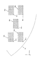
本実施形態では、投影光学系PLの光学特性を計測するために、2枚のレチクルRTH、RTVが用いられる。図2には、そのうちの1枚のレチクルRTHが示されている。図2は、レチクルRTHをパターン面側(図1における下面側)から見た平面図である。図2に示されるように、レチクルRTHは、矩形(正確には正方形)のガラス基板42から成り、そのパターン面には不図示の遮光帯によって規定されるほぼ長方形のパターン領域PAが形成され、本例(図2の例)ではクロム等の遮光部材によってそのパターン領域PAのほぼ全面が遮光部となっている。パターン領域PAの中心(ここではレチクルRTHの中心(レチクルセンタ)に一致)、及びレチクルセンタを中心とし、かつX軸方向を長手方向とする仮想の矩形領域IAR’内部の4隅の部分の合計5箇所に、所定幅、例えば一辺が27μmの正方形の開口パターン(透過領域)AP1〜AP5が形成され、開口パターンAP1〜AP5内に計測用パターン(以下、適宜、パターンと略述する)MPH1〜MPH5がそれぞれ形成されている。上記矩形領域IAR’は、前述の照明領域にほぼ一致する大きさ及び形状となっている。なお、本例ではパターン領域PAのほぼ全面を遮光部としたが、パターン領域PAを光透過部としても良い。この場合、上記矩形領域IAR’はX軸方向の両端が前述の遮光帯で規定されるので、Y軸方向の両端にそれぞれ所定幅(例えば遮光帯と同じ幅)の遮光部を設けても良い。
In the present embodiment, two reticles R TH and R TV are used to measure the optical characteristics of the projection optical system PL. FIG. 2 shows one of the reticles R TH . FIG. 2 is a plan view of reticle RTH viewed from the pattern surface side (lower surface side in FIG. 1). As shown in FIG. 2, the reticle R TH is composed of a rectangular (exactly square)
パターンMPHn(n=1〜5)のそれぞれは、例えば所定の線幅、例えば0.6μmで、所定の長さ、例えば9μm程度の3本(又は5本)のラインパターンが所定のピッチ、例えば2.0μmでX軸方向に配列されたマルチバーパターンによって構成されている。以下では、パターンMPHnを便宜上H線パターンとも呼ぶ。 Each of the patterns MP Hn (n = 1 to 5) has, for example, a predetermined line width, for example, 0.6 μm, and a predetermined length, for example, three (or five) line patterns of about 9 μm have a predetermined pitch, For example, it is constituted by a multi-bar pattern arranged in the X-axis direction at 2.0 μm. Hereinafter, the pattern MP Hn is also referred to as an H line pattern for convenience.
また、前述のレチクルセンタを通るパターン領域PAのX軸方向の両側には、一対のレチクルアライメントマークRM1,RM2が形成されている(図2参照)。 A pair of reticle alignment marks RM1 and RM2 are formed on both sides in the X-axis direction of the pattern area PA passing through the reticle center (see FIG. 2).
図3には、もう1枚のレチクルRTVが示されている。図3は、レチクルRTVをパターン面側(図1における下面側)から見た平面図である。図3に示されるように、レチクルRTVは、前述のレチクルRTHと同様に、ガラス基板42を有し、そのパターン面に不図示の遮光帯によって規定される前述のパターン領域PAと同一の形状かつ大きさのパターン領域PA’が形成され、そのパターン領域PA’のほぼ全面が遮光部となっている。ただし、本例では、開口パターンAP1〜AP5の内部に計測用パターン(以下、適宜、パターンと略述する)MPV1〜MPV5がそれぞれ形成されている。パターンMPV1〜MPV5のそれぞれは、配列方向(周期方向)がY軸方向である点を除き、パターンMPHnと同様のマルチバーパターンによって構成されている。以下では、パターンMPVnを、便宜上V線パターンとも呼ぶ。なお、パターン領域PA’はその全面が光透過部でも良い。
FIG. 3 shows another reticle R TV . FIG. 3 is a plan view of reticle R TV viewed from the pattern surface side (lower surface side in FIG. 1). As shown in FIG. 3, the reticle R TV has a
次に、本実施形態の露光装置100における投影光学系PLの光学特性の計測方法について、主制御装置28内のCPUの処理アルゴリズムを簡略化して示す図4のフローチャートに沿って、かつ適宜他の図面を用いて説明する。以下では、説明の便宜上から計測用パターン(又はパターン)MPnという用語を用いるが、これは、特に明示がない場合、レチクルRTHを使用中のときは、パターンMPHnを意味し、レチクルRTVを使用中のときは、パターンMPVnを意味する。また、初期設定として、後述するフラグFは降ろされている(F=0である)ものとする。
Next, with respect to the method for measuring the optical characteristics of the projection optical system PL in the
まず、図4のステップ402において、ウエハ交換を行う。具体的には、不図示のウエハアンローダを介してウエハテーブル18上からウエハをアンロードした後、不図示のウエハローダを介してウエハWT(図5参照)をウエハテーブル18上にロードする。なお、ウエハテーブル18上にウエハがない場合には、ウエハWTのロードのみを行う。
First, in
次に、ステップ404において、レチクル交換、レチクルの投影光学系PLに対する位置合わせ等の所定の準備作業を行う。
Next, in
具体的には、不図示のレチクル交換機構を介してレチクルステージRST上のレチクルと第1番目のレチクルRTHとを交換する。なお、レチクルステージRST上にレチクルがない場合には、単にレチクルRTHをロードする。 Specifically, replacing the reticle and the 1st reticle R TH on the reticle stage RST via a reticle exchange mechanism (not shown). When there is no reticle on the reticle stage RST, simply loads the reticle R TH.
次いで、前述のレチクルアライメント検出系(不図示)によって、ウエハテーブル18に設けられた基準板FP上の一対の基準マーク(不図示)と、レチクルステージRST上のレチクル(この場合、レチクルRTH)の一対のレチクルアライメントマークRM1、RM2とが検出されるように、それぞれレーザ干渉計14、26の計測値に基づいてレチクルステージRSTとウエハステージWSTとを移動させる。そして、前述のレチクルアライメント検出系の検出結果に基づいてレチクルステージRSTのXY平面内の位置(回転を含む)を調整する。これにより、前述の照明領域内に使用中のレチクル(この場合、レチクルRTH)の矩形領域IAR’が設定され、その全面が照明光ILで照射されることとなる。また、本実施形態では投影光学系PLを介してその視野(特に露光エリア)内で計測用パターンMPnの投影像(パターン像)が生成される位置が、投影光学系PLの露光エリア内でその光学特性(例えばフォーカス)を計測すべき評価点となる。なお、その評価点の数は、実際には5つより多いが、本実施形態では、説明の便宜上から、前述した露光エリアの中心及び4隅の計5つの評価点が設定されているものとしている。ただし、評価点(計測用パターンMPn)の数は、少なくとも1つあれば良い。
Next, a pair of reference marks (not shown) on the reference plate FP provided on the wafer table 18 and a reticle on the reticle stage RST (in this case, reticle R TH ) by the above-described reticle alignment detection system (not shown). The reticle stage RST and wafer stage WST are moved based on the measurement values of the
このようにして、所定の準備作業が終了すると、次のステップ406(露光処理のサブルーチン)に移行する。 When the predetermined preparation work is completed in this way, the process proceeds to the next step 406 (exposure processing subroutine).
このサブルーチンでは、まず、図7に示されるように、ステップ502において、ウエハWT上に照射される照明光ILの単位面積当たりの量(露光量)、すなわちドーズ量の目標値(目標ドーズ量と呼ぶ)Pjを初期化する。すなわち、カウンタjに初期値「1」を設定して目標ドーズ量PjをP1に設定する(j←1)。本実施形態では、カウンタjは、目標ドーズ量の設定とともに、露光の際のウエハWTの行方向の移動目標位置の設定にも用いられる。なお、本実施形態では、例えばウエハWT上に塗布された感応剤(レジスト)の感度特性から予想される最適ドーズ量を中心として、目標ドーズ量を、P1からPN(一例として、N=23とする)まで、ΔP刻みで変化させる(Pj=P1〜P23)。
In this subroutine, first, as shown in FIG. 7, in
次のステップ504では、ウエハWTのフォーカス位置(Z軸方向の位置)の目標値(以下、目標フォーカス位置と呼ぶ)Ziを初期化する。すなわち、カウンタiに初期値「1」を設定してウエハWTの目標フォーカス位置ZiをZ1に設定する(i←1)。本実施形態では、カウンタiは、ウエハWTの目標フォーカス位置の設定とともに、露光の際のウエハWTの列方向の移動目標位置の設定にも用いられる。なお、本実施形態では、例えば投影光学系PLに関する既知の最良フォーカス位置(設計値など)を中心として、ウエハWTの目標フォーカス位置をZ1からΔZ刻みでZM(一例としてM=13とする)まで変化させる(Zi=Z1〜Z13)。
In the
従って、本実施形態では、投影光学系PLの光軸方向に関するウエハWTの位置とウエハWT上に照射される照明光ILのドーズ量とをそれぞれ変更しながら、パターンMPn(n=1〜5)をウエハWT上に順次転写するための、M×N(一例として13×23=299)回の露光が行われることになる。投影光学系PLの視野内の各評価点に対応するウエハWT上の領域(以下「評価点対応領域」という)DB1〜DB5(図5及び図6参照)には、M×N個のパターンMPnが転写されることとなる。 Accordingly, in the present embodiment, while changing the position and the dose of illumination light IL irradiated on wafer W T of the wafer W T to an optical axis of the projection optical system PL respectively, patterns MP n (n = 1 for sequentially transferring 5) on the wafer W T, so that the exposure of the 13 × 23 = 299) times as M × N (an example is performed. The projection optical system PL wafer W T on a region (hereinafter referred to as "evaluation point corresponding region") DB 1 to DB 5 corresponding to each evaluation point in the visual field (see FIG. 5 and FIG. 6) is, M × N number The pattern MP n is transferred.
なお、この評価点対応領域DBnは、投影光学系PLの視野内でその光学特性を検出すべき複数の評価点に対応している。 The evaluation point corresponding area DB n corresponds to a plurality of evaluation points whose optical characteristics are to be detected within the field of view of the projection optical system PL.
ここで、説明は前後するが、便宜上、後述する露光によって、パターンMPnが転写されるウエハWT上の各評価点対応領域DBnについて、図6を用いて説明する。この図6に示されるように、本実施形態では、M行N列(13行23列)のマトリックス状に配置されたM×N(=13×23=299)個の仮想の区画領域DAi,j(i=1〜M、j=1〜N)にパターンMPnがそれぞれ転写され、これらパターンMPnがそれぞれ転写されたM×N個の区画領域DAi,jから成る評価点対応領域DBnがウエハWT上に形成される。なお、仮想の区画領域DAi,jは、図6に示されるように、+X方向が行方向(jの増加方向)となり、+Y方向が列方向(iの増加方向)となるように配列されている。また、以下の説明において用いられる添え字i,j、及びM,Nは、上述と同じ意味を有するものとする。 Here, description will be back and forth, for convenience, the exposure that will be described later, for each evaluation point corresponding area DB n on wafer W T that pattern MP n is transferred will be described with reference to FIG. As shown in FIG. 6, in this embodiment, M × N (= 13 × 23 = 299) virtual partition areas DA i arranged in a matrix of M rows and N columns (13 rows and 23 columns). , J (i = 1 to M, j = 1 to N), the pattern MP n is transferred respectively , and the evaluation point corresponding area composed of M × N partition areas DA i, j to which these patterns MP n are transferred respectively. DB n are formed on the wafer W T. The virtual partition areas DA i, j are arranged so that the + X direction is the row direction (increase direction of j) and the + Y direction is the column direction (increase direction of i), as shown in FIG. ing. Further, the subscripts i and j and M and N used in the following description have the same meaning as described above.
図4に戻り、次のステップ506では、レーザ干渉計26の計測値をモニタしつつ駆動系22を介してXYステージ20を移動させて、ウエハWT上の各評価点対応領域DBnの仮想の区画領域DAi,j(ここではDA1,1(図5参照))に計測用パターンMPnの像がそれぞれ転写される位置に、ウエハWTを位置決めする。
Returning to FIG. 4, in the
次のステップ508では、フォーカスセンサAFSからの計測値をモニタしながらウエハテーブル18をZ軸方向及び傾斜方向に微少駆動して、ウエハWTのZ軸方向の位置を設定された目標フォーカス位置Zi(この場合Z1)に設定する。
In the
次のステップ510では、露光を実行する。このとき、ウエハWT上のドーズ量が設定された目標ドーズ量(この場合P1)となるように、露光量制御を行う。ドーズ量は、照明光ILのパルスエネルギ量と、露光時にウエハ上に照射される照明光ILのパルス数との少なくとも一方を変更することで調整できる。これにより、図5に示されるように、ウエハWT上の各評価点対応領域DBnの区画領域DA1,1にそれぞれ計測用パターンMPn(この場合パターンMPHn)の像が転写される。
In the
次のステップ512では、ウエハWTの目標フォーカス位置(カウンタiのカウント値)を確認し、所定の範囲(すなわち目標フォーカス位置Z1からZMについて)の露光が終了したか否かを判断する。ここでは、最初の目標フォーカス位置Z1での露光が終了しただけなので、ステップ514に移行し、カウンタiを1インクリメントする(i←i+1)とともに、ウエハWTのフォーカス位置の目標値にΔZを加算する(Zi←Zi+1=Zi+ΔZ)。ここでは、フォーカス位置の目標値をZ2(=Z1+ΔZ)に変更した後、ステップ506に戻る。そして、ステップ512での判断が肯定されるまで、ステップ506、508、510、512、514の処理(判断を含む)を繰り返す。ここで、ステップ506では、繰り返す毎に、XYステージ20を所定のステップピッチだけXY平面内で所定方向(この場合−Y方向)に移動させて、逐次、ウエハWT上の各評価点対応領域DBnの区画領域DAi,1に計測用パターンMPnの像がそれぞれ転写される位置にウエハWTを位置決めする。そして、ステップ508において、ウエハWTを目標フォーカス位置Ziに位置決めし、ステップ510において、先と同様に、ウエハWT上の各評価点対応領域DBnの区画領域DAi,1に計測用パターンMPnの像をそれぞれ転写する。これにより、ウエハWT上の各評価点対応領域DBnの区画領域DAi,1(i=1〜M)に計測用パターンMPn(この場合パターンMPHn)がそれぞれ転写される。
In the
一方、区画領域DAM,1への露光が終了し、ステップ512における判断が肯定されると、ステップ516に移行し、目標ドーズ量(カウンタjのカウント値)を確認し、所定の範囲(すなわち目標ドーズ量P1からPNについて)の露光が終了したか否かを判断する。ここでは、そのとき設定されている目標ドーズ量はP1であるため、このステップ516における判断は、否定され、ステップ518に移行する。
On the other hand, when the exposure to the partition area DAM , 1 is completed and the determination in
ステップ518では、カウンタjを1インクリメントする(j←j+1)とともに、目標ドーズ量PjにΔPを加算する(Pj←Pj+1=Pj+ΔP)。ここでは、目標ドーズ量をP2(=P1+ΔP)に変更した後、ステップ504に戻る。そして、ステップ516での判断が肯定されるまで、ステップ504、(506、508、510、512、514)、516、518の処理(判断を含む)を繰り返す。これにより、ウエハWT上の各評価点対応領域DBnの全ての区画領域DAi,j(i=1〜M,j=1〜N)に計測用パターンMPn(この場合、パターンMPHn)の像が転写される。
In
このようにして、所定の範囲の目標ドーズ量(P1〜PN)についての露光が終了すると、ステップ516における判断が肯定され、本サブルーチンの処理を終了して、図4(メインルーチン)のステップ408に移行(リターン)する。ステップ406の処理により、図5に示されるように、ウエハWT上の各評価点対応領域DBnには、露光条件が異なるN×M(一例として23×13=299)個の計測用パターンMPn(この場合、パターンMPHn)の転写像(潜像)が形成される。なお、実際には、上述のようにして、ウエハWT上に計測用パターンMPnの転写像(潜像)が形成されたM×N(一例として13×23=299)個の区画領域が形成された段階で、各評価点対応領域DBnが形成されるのであるが、上記の説明では、説明を分かり易くするために、評価点対応領域DBnが予めウエハWT上にあるかのような説明方法を採用したものである。
In this way, when the exposure for the target dose amount (P 1 to P N ) within a predetermined range is completed, the determination in
ステップ408では、ウエハWTを、ウエハアンローダ(不図示)を介してウエハテーブル18上からアンロードした後、ウエハ搬送系(不図示)を介してコータ・デベロッパ(不図示)に搬送する。ここで、コータ・デベロッパ(不図示)は、インラインにて露光装置100に接続されている。
In
上記のコータ・デベロッパに対するウエハWTの搬送後に、ステップ410に進んでウエハWTの現像が終了するのを待つ。このステップ410における待ち時間の間に、コータ・デベロッパによってウエハWTの現像が行われる。この現像の終了により、ウエハWT上には、図5に示されるような矩形の評価点対応領域DBn(n=1〜5)のレジスト像が形成され、このレジスト像が形成されたウエハWTが後述するステップ417で最適ドーズ量等を仮決定するための試料となる。
After transfer of the wafer W T to the above coater developer, development of wafer W T waits for the end proceeds to step 410. During the waiting time in
上記ステップ410の待ち状態で、不図示のコータ・デベロッパの制御系からの通知によりウエハWTの現像が終了したことを確認すると、ステップ412に移行する。
In the wait state of
ステップ412では、不図示のウエハローダに指示を出して、前述のステップ402と同様にして現像済みのウエハWTをウエハテーブル18上にロードする。
In
次のステップ414では、現像済みのウエハWTを用いて、最適ドーズ量を求めるのに用いることができる基礎データを取得するため、所定の画像処理を行う。
In the
具体的には、主制御装置20は、ウエハWT上の評価点対応領域DB1〜DB5のそれぞれについて、以下のa.〜d.の処理を行う。
a. まず、主制御装置28は、ウエハWT上の評価点対応領域DBnのレジスト像を、アライメント系AS(のFIA系のセンサ)を用いて撮像し、その撮像データを取り込む。アライメント系ASは、レジスト像を撮像素子(CCD等)のピクセル単位に分割し、ピクセル毎に対応するレジスト像の濃淡を例えば8ビットのデジタルデータ(ピクセルデータ)として主制御装置28に供給する。すなわち、前記撮像データは、複数のピクセルデータで構成されている。この場合、レジスト像の濃度が高くなる(黒に近くなる)につれてピクセルデータの値は大きくなるものとする。この場合、アライメント系AS(のFIA系センサ)により、評価点対応領域DBnのN×M個の区画領域DAi,jを含む領域を同時に(一括して)撮像可能となっているものとする。
b. 次いで、主制御装置28は、例えば特開平2004−146702号公報、米国特許出願公開第2004/0179190号明細書などに開示される方法により、その撮像データを画像処理して評価点対応領域DBnの外縁を検出する。
Specifically, the
a. First, the
b. Then, the
c. 次いで、主制御装置28は、上で検出した評価点対応領域DBnの外縁、すなわち長方形の枠線の内部を、既知の区画領域の縦方向の数M及び横方向の数Nを用いて、等分割することで、区画領域DA1,1〜DAM,Nを求める。すなわち、外縁を基準として、各区画領域DAi,j(の位置情報)を求める。
c. Next, the
d. 次いで、主制御装置28は、各区画領域DAi,j(i=1〜M、j=1〜N)に形成されたレジスト像毎の明暗情報、例えばコントラスト値Ei,jを算出し、その算出結果をメモリに記憶する。ここで、コントラスト値Ei,jは、例えば、ピクセルデータの分散(又は標準偏差)により与えられる。あるいは、コントラスト値Ei,jは、ピクセルデータの値の最大LMAXと最小LMINとからEi,j=(LMAX−LMIN)/(LMAX+LMIN)と与えられても良い。
d. Next, the
上述の画像処理が終了すると、次のステップ416に進み、レチクルRTVを用いた処理は終了したか否かを判断する。この場合、未だレチクルRTVを用いた処理は行われていないので、このステップ416における判断は否定され、ステップ402に戻る。
When the above-described image processing is completed, the process proceeds to the
ステップ402では、前述と同様にしてウエハ交換を行った後、ステップ404で、レチクル交換を行うが、この際、レチクルRTHに代えてレチクルRTVがレチクルステージRST上にロードされる。また、この交換後のレチクルRTVの投影光学系PLに対する位置合わせ等の準備作業が行われる。
In
その後、レチクルRTVを用いた処理(ステップ406〜414の処理)が、前述と同様にして行われる。
Thereafter, the processing using the reticle R TV (the processing in
そして、ステップ416において、再び、主制御装置28により、レチクルRTVを用いた処理は終了したか否かが判断される。この場合、レチクルRTVを用いた処理は終了しているので、ここでの判断は肯定されて、ステップ417に移行する。
In
ステップ417では、次のe.〜g.の手順に従って、最適ドーズ量及び最良フォーカス位置を仮決定する。
e. まず、主制御装置28は、各評価点対応領域DBnについて、ドーズ量Pj及び計測パターンの種類(H線、V線)毎に、算出された各区画領域DAi,jのコントラスト値Ei,jを、図8に示されるように、フォーカス位置Ziに対してプロットする。
In
e. First, for each evaluation point corresponding area DB n , the
図8からわかるように、コントラスト値Ei,jは、ドーズ量Pjが高い(低い)ほど、低い(高い)。ここで、最適範囲(Opt. Dose)内のドーズ量Pjに対し、プロット点を結ぶコントラストカーブは、理想的なプロファイル、すなわち山の形状(凸状)のプロファイルを示す。また、最適範囲(Opt. Dose)より高いドーズ量Pj(領域Over Dose内のドーズ量Pj)では、コントラストカーブは山の形状のプロファイルを示すが、有効データが少なくなる。さらに、最適範囲(Opt. Dose)より低いドーズ量Pj(領域Under Dose内のドーズ量Pj)では、ドーズ量Pjが低いほど、コントラストカーブのピークプロファイルが崩れ、ドーズ量Pjがある値より低くなると、谷の形状(凹状)のプロファイルを示すようになる。
f. 次に、主制御装置28は、各評価点対応領域DBnについて、ドーズ量Pj及び計測パターンの種類(H線、V線)毎に、コントラストカーブ及び/又は各区画領域DAi,j(i=1〜M、j=j)に形成されたレジスト像のコントラスト値Ei,jのデータを用いて、最適ドーズ量Poptnを求める。ここで、最適ドーズ量は、コントラストカーブが理想的なプロファイルを示すドーズ量である。そこで、主制御装置28は、例えば、理想的なプロファイルを記述する近似関数を与え、各コントラスト値Ei,jのデータを最小自乗フィッティングし、フィッティング後の曲線(近似関数)からの各コントラスト値Ei,jのずれが最小となるドーズ量を最適ドーズ量Poptnとする。また、主制御装置28は、必要に応じ、例えば複数のドーズ量についてのコントラストカーブ間でのずれが同程度であるような場合には、非点収差(V線パターン及びH線パターンそれぞれに対するコントラストカーブから求められる最良フォーカス位置同士の差)が最小となるドーズ量Pjを、最適ドーズ量Poptnとする。
As can be seen from FIG. 8, the contrast value E i, j is lower (higher) as the dose Pj is higher (lower). Here, the contrast curve connecting the plot points with respect to the dose amount P j within the optimum range (Opt. Dose) shows an ideal profile, that is, a mountain-shaped (convex) profile. Further, the optimum range (Opt. Dose) higher dose P j (a dose P j in the region Over Dose), the contrast curve indicates the profile of the mountain shape, the effective data is less. Further, the optimum range (dose P j in the region Under Dose) low dose P j from (Opt. Dose), the lower the dose P j, collapsed peak profile of the contrast curve, there is a dose P j When the value is lower than the value, a valley-shaped (concave) profile is shown.
f. Next, for each evaluation point corresponding area DB n , the
g. 次に、主制御装置28は、評価点対応領域DB1〜DB5に対して求められた最適ドーズ量Popt1〜Popt5のうち、例えば中央の大きさを有する仮の最適ドーズ量Poptを求め(最適ドーズ量Poptを仮決定し)、メモリに記憶する。また、主制御装置28は、仮の最適ドーズ量Poptに対応するコントラストデータから仮の最良フォーカス位置を求め(最良フォーカス位置を仮決定し)、メモリに記憶する。
g. Next, the
このようにして最適ドーズ量Popt及び最良フォーカス位置の仮決定を行った後、ステップ418に移行する。 After the optimum dose amount P opt and the best focus position are tentatively determined in this way, the process proceeds to step 418.
ステップ418では、前述のステップ402と同様にしてウエハ交換を行った後、次のステップ420に進み、前述のフラグFが降ろされた状態(F=0)であるか否かを判断する。この場合、フラグFは初期設定で0とされているので、ここでの判断は肯定され、ステップ424に移行する。
In
ステップ424では、前述したステップ406と同様の手順で露光処理を行う。これにより、レチクルRTVのパターンPMVnが、ウエハWT上に転写され、評価点対応領域DB1〜DB5がそのウエハWT上に形成される。重複説明を避ける観点からステップ424の詳細説明は省略する。ただし、主制御装置28は、このステップ424では、先に求めた仮の最適ドーズ量Poptを中心とする所定の範囲(先のP1〜PNの範囲より狭い範囲)内で、ドーズピッチΔPを先より狭く設定して、目標ドーズ量を、N段階で変化させる。この場合、図8に示される最適範囲(Opt. Dose)内で目標ドーズ量を、変化させるのが望ましい。また、主制御装置28は、このステップ424では、先に求めた仮の最良フォーカス位置を中心とする所定の範囲(先のZ1〜ZNの範囲より狭い範囲)内で、フォーカスピッチΔZを先より狭く設定して、目標フォーカス位置を、M段階で変化させる。
In
次に、ステップ426〜ステップ432において、前述のステップ408〜414と同様の処理(判断を含む)を行った後、ステップ434に移行する。
Next, in
ステップ434では、レチクルRTHを用いた処理は終了したか否かを判断する。この場合、未だレチクルRTHを用いた処理は行われていないので、このステップ434における判断は否定され、ステップ435に移行してフラグFを立て(F←1)、ステップ418に戻る。
In
ステップ418では、前述と同様にしてウエハ交換を行う。
In
次のステップ420で、フラグFが降ろされているか否かを再度判断する。この場合、フラグFは立てられている(F=1)であるので、ステップ422に移行する。
In the
ステップ422で、ステップ404と同様に、レチクル交換を行う。ここでは、レチクルRTVに代えてレチクルRTHがレチクルステージRST上にロードされる。また、交換後のレチクルRTHの投影光学系PLに対する位置合わせ等の準備作業を行う。
In
そして、ステップ424で、前述の手順で露光処理を行う。これにより、レチクルRTHのパターンPMHnが、ウエハWT上に転写され、評価点対応領域DB1〜DB5がそのウエハWT上に形成される。
In
次に、ステップ426〜ステップ432において、前述のステップ408〜414と同様の処理(判断を含む)を行った後、ステップ434に移行する。
Next, in
ステップ434では、レチクルRTHを用いた処理は終了したか否かを判断する。この場合、レチクルRTHを用いた処理は行われているので、このステップ434における判断は肯定され、ステップ436に移行する。
In
この時点で、図8に示される最適範囲(Opt. Dose)内において、より多くのドーズ量毎のコントラストデータ(コントラストカーブ)が得られている。そこで、ステップ436では、ステップ417と同様の手順で、それらのコントラストデータ(コントラストカーブ)を用いて最適ドーズ量Poptを決定する。
At this point, more contrast data (contrast curve) for each dose amount is obtained within the optimum range (Opt. Dose) shown in FIG. Therefore, in
次のステップ438では、投影光学系PLの光学特性、例えば最良フォーカス位置を算出する。具体的には、主制御装置28は、ステップ436において決定された最適ドーズ量Poptに対応する、各評価点対応領域DBnのコントラストデータ(コントラストカーブ)に基づいて、例えばコントラストカーブのピーク中心より、最良フォーカス位置を、Hパターン、Vパターンのそれぞれについて、評価点対応領域DBn毎に、最良フォーカス位置を求める。次いで、主制御装置28は、評価点対応領域DBn毎に、Hパターン、Vパターンのそれぞれについて求めた最良フォーカス位置の平均値を、投影光学系PLの視野内の各評価点における最良フォーカス位置として算出する。さらに、主制御装置28は、評価点対応領域DB1〜DB5に対応する評価点における最良フォーカス位置の平均値(又は重み付け平均値)を、投影光学系PLの最良フォーカス位置Zbestとして算出する。
In the
また、主制御装置28は、投影光学系PLの視野内の各評価点における最良フォーカス位置に基づいて、像面形状を算出する。また、主制御装置28は、評価点対応領域DBn毎に、Hパターン、Vパターンのそれぞれについて求めた最良フォーカス位置の差に基づいて、評価点対応領域DB1〜DB5に対応する評価点における非点収差を算出しても良い。
Further,
なお、ステップ438に代えて、前述のステップ402〜416、又はステップ418〜434の処理を、目標ドーズ量をステップ436で決定した最適ドーズ量に固定した状態で、再度行って、コントラストデータ(コントラストカーブ)を求め、その求めたコントラストデータに基づいて、上記と同様の手順で投影光学系PLの光学特性を求めるステップを設けても良い。
In place of
主制御装置28は、上述のようにして求めた投影光学系PLの光学特性を補正すべく、不図示の結像特性補正コントローラを介して投影光学系PLの光学特性(結像特性を含む)を調整する。そして、主制御装置28は、光学特性が調整された投影光学系PLを介して、レチクルRに形成されたパターンをウエハW上に転写する。さらに、主制御装置28は、露光の際に、フォーカスセンサAFSを用いて、最良フォーカス位置を基準として、ウエハWのフォーカス制御を行うことにより、デフォーカスによる色むらの発生を効果的に抑制することができる。これにより、ウエハ上に微細パターンを高精度に転写することが可能となる。なお、主制御装置28は、露光に先立って、フォーカスセンサを最良フォーカス位置を基準として較正しても良い。
The
以上説明したように、本実施形態によると、ステップ417において、ステップ406の露光処理(ステップ502〜518)によってウエハWT上の評価点対応領域DBnのM×N個の区画領域DAi,jに形成された計測用パターンMPnの像の形成状態の検出結果に基づいて、投影光学系PLの光学特性計測のための計測用パターンMPnを用いる露光の最適ドーズ量(及び最良フォーカス位置)が仮に決定される。
As described above, according to this embodiment, in
そして、ステップ424の露光処理により、目標ドーズ量(及び目標フォーカス位置)を、仮に決定された最適ドーズ量(及び最良フォーカス位置)を中心としてより細かいステップピッチで複数段階で変化させて、ステップ406の露光処理と同様の露光処理により計測用パターンMPnが投影光学系PLを介してウエハWT上の評価点対応領域DBnのM×N個の領域に順次転写される。従って、投影光学系PLの光学特性計測のための露光条件の一部が微調整される。
Then, by the exposure processing in
そして、その微調整された露光条件の下で行われた露光によってウエハWT上の各区画領域に形成された計測用パターンMPnの像の形成状態の検出結果に基づいて、投影光学系PLの光学特性が求められる(ステップ436、438)。従って、投影光学系の光学特性を精度良く求めることが可能になる。
Then, based on the detection result of the formation state of the fine-tuned image of the wafer W T measurement pattern MP n formed in each divided area on the exposure performed under the exposure condition, the projection optical system PL Are obtained (
また、本実施形態の露光装置100によると、投影光学系PLの光学特性を前述した光学特性計測方法により精度良く計測し、その光学特性の計測結果を考慮して、投影光学系PLの光学特性を調整し、その光学特性が調整された投影光学系PLを介して、レチクルRに形成されたパターンをウエハW上に転写する。露光の際、最良フォーカス位置を基準としてフォーカスセンサAFSを用いてウエハWのフォーカス制御を行う。これにより、
ウエハ上に微細パターンを高精度に転写することが可能となる。
Further, according to the
It becomes possible to transfer the fine pattern onto the wafer with high accuracy.
なお、上記実施形態では、H線パターンとV線パターンとのそれぞれについて、コントラストデータ(コントラストカーブ)を得、これらのコントラストデータ(コントラストカーブ)に基づいて、最適ドーズ、又は投影光学系の光学特性を算出する場合について説明したが、これに限らず、H線パターンとV線パターンとの一方についてコントラストデータ(コントラストカーブ)を得、このコントラストデータ(コントラストカーブ)に基づいて、最適ドーズ、又は投影光学系の光学特性を算出することとしても良い。 In the above embodiment, contrast data (contrast curve) is obtained for each of the H-line pattern and the V-line pattern, and the optimal dose or the optical characteristics of the projection optical system is obtained based on the contrast data (contrast curve). However, the present invention is not limited to this, and contrast data (contrast curve) is obtained for one of the H-line pattern and V-line pattern, and an optimal dose or projection is performed based on the contrast data (contrast curve). The optical characteristics of the optical system may be calculated.
また、上記実施形態では、H線パターンとV線パターンとがそれぞれ設けられた2つのレチクルを用いて、H線パターンとV線パターンとを、別々のウエハ上に転写する場合について説明したが、これに限らず、H線パターンとV線パターンとが設けられた単一のレチクルを用いて、H線パターンとV線パターンとを、同一又は別のウエハ上に転写することとしても良い。 In the above embodiment, the case where the H line pattern and the V line pattern are transferred onto separate wafers using two reticles each provided with the H line pattern and the V line pattern has been described. The present invention is not limited to this, and the H line pattern and the V line pattern may be transferred onto the same or different wafers using a single reticle provided with the H line pattern and the V line pattern.
また、上記実施形態において、理想的なプロファイルを得るため、前述の最小自乗フィッティングによっては、フィッティング度の十分な近似曲線が得られなかったとき、より低次の近似関数を用いて前述の最小自乗フィッティングを行って理想的なプロファイルを表す近似曲線を得ることとしても良い。同様に観点から、ステップ417とステップ436とで、コントラスト値Ei,jのデータを最小自乗フィッティングするための近似関数(理想的なプロファイルを記述する関数)の次数を、異ならせても良い。この場合、ステップ436において、より低次の近似関数を用いてコントラスト値Ei,jのデータを最小自乗フィッティングすることが望ましい。また、最小自乗フィッティングによって台形状のプロファイルが得られるような場合には、最小自乗フィッティングの有効データと無効データとの切り分けを行うパラメータを調整して、より多くのデータが有効となるようにしても良い。
Further, in the above embodiment, in order to obtain an ideal profile, when the above-mentioned least square fitting does not provide a sufficient approximate curve of the fitting degree, a lower-order approximation function is used to obtain the aforementioned least square. An approximate curve representing an ideal profile may be obtained by fitting. Similarly, from the viewpoint, the order of the approximation function (function for describing an ideal profile) for performing least square fitting of the data of the contrast value E i, j may be different between
また、上記実施形態では投影光学系の光学特性として最良フォーカス位置、像面湾曲、あるいは非点収差を求めるものとしたが、その光学特性はこれらに限られるものでなく他の収差などでも良い。また、上記実施形態では、ウエハWTの表面にポジ型のレジストにより感応層が形成されるものとしたが、これに限らず、ネガ型のレジストにより感応層を形成しても良い。 In the above embodiment, the best focus position, field curvature, or astigmatism is obtained as the optical characteristics of the projection optical system. However, the optical characteristics are not limited to these, and other aberrations may be used. In the above embodiment, the surface of the wafer W T by a positive resist was assumed that sensitive layer is formed, this is not limited, it may be formed sensitive layer by a negative resist.
ところで、計測用パターンとして、例えばライン部とスペース部との幅の比(デューティ比)が1のラインアンドスペースパターン(L/Sパターン)を採用した場合には、ウエハ上に投影光学系を介して投影された像の線幅(正確には、ライン部の幅及びスペース部の幅のうち大きい方)が、アライメント系ASのFIA系のセンサの解像限界と同程度以下になると、実際には存在しない枠線がパターンの周囲に出現し、計測誤差の要因になることが知られている。かかる不都合を改善するため、1回目の露光でL/Sパターンを投影光学系を介してポジ型レジストが塗布されたウエハ上に投影して、L/Sパターンの像(潜像)を形成した後、2回目の露光(トリム露光)を行って、その潜像の一部を除去することで、結果的に、デューティ比が1/3以下である孤立線パターンと同様のパターンの潜像をウエハ上に形成し、該ウエハを現像して、計測用パターン像(レジスト像)(ただし、この計測用パターン像は、L/Sパターンの像と同じ特性(線幅など)を有している)を形成し、該計測用パターン像を用いて投影光学系の光学特性を計測する方法を、発明者は先に提案した(国際公開第2008/132799号パンフレット及びこれに対応する米国特許出願公開第2008/0259353号明細書参照)。トリム露光を採用することで、ウエハの現像後には、図14(A)の像と図14(B)の像とを重ね合わせた像、別の表現をすれば、図14(A)の像と図14(B)の像との共通部分である、図14(C)に示される断面形状を有するレジスト像が得られる。 By the way, for example, when a line and space pattern (L / S pattern) having a width ratio (duty ratio) between the line portion and the space portion of 1 is adopted as the measurement pattern, the projection optical system is provided on the wafer. When the line width of the projected image (more precisely, the larger of the width of the line portion and the width of the space portion) is less than or equal to the resolution limit of the FIA sensor of the alignment system AS, It is known that a non-existent frame line appears around the pattern and causes measurement errors. In order to improve such inconvenience, an L / S pattern image (latent image) is formed by projecting an L / S pattern onto a wafer coated with a positive resist via a projection optical system in the first exposure. Thereafter, a second exposure (trim exposure) is performed to remove a part of the latent image, and as a result, a latent image having a pattern similar to an isolated line pattern having a duty ratio of 1/3 or less is obtained. A pattern image for measurement (resist image) formed on a wafer and developed to develop the wafer (however, this pattern image for measurement has the same characteristics (line width, etc.) as the image of the L / S pattern) The inventors previously proposed a method for measuring the optical characteristics of the projection optical system using the measurement pattern image (International Publication No. 2008/132799 and published US patent application corresponding thereto) 2008/0259353 Reference herein). By adopting trim exposure, after the development of the wafer, an image obtained by superimposing the image of FIG. 14A and the image of FIG. 14B, in other words, the image of FIG. 14A. And a resist image having a cross-sectional shape shown in FIG. 14C, which is a common part of the image of FIG. 14B.
しかるに、最近では、上述したトリム露光の際の露光条件、例えばドーズ量も、一層精度良く設定する必要が生じている。次に説明する第2の実施形態は、かかる点に鑑みて成されたものである。 However, recently, it is necessary to set the exposure conditions for the above-described trim exposure, for example, the dose amount with higher accuracy. The second embodiment to be described next has been made in view of this point.
《第2の実施形態》
次に、本発明の第2実施形態について、図9(A)〜図14(C)に基づいて説明する。本第2の実施形態に係る露光装置は、投影光学系の光学特性の計測に際しての、主制御装置28の処理アルゴリズムが、前述の第1の実施形態と相違する点を除けば、前述の第1の実施形態と同様に構成され、同様に機能する。従って、以下では、重複説明を避ける観点から、相違点を中心として説明する。また、同様の趣旨から、同一若しくは同等の構成部分については、同一の符号を用いるものとする。
<< Second Embodiment >>
Next, 2nd Embodiment of this invention is described based on FIG. 9 (A)-FIG. 14 (C). The exposure apparatus according to the second embodiment is the same as that described above except that the processing algorithm of the
本第2の実施形態では、投影光学系PLの光学特性を計測するために、2枚のレチクルR1、R2が用いられる。レチクルR1、R2は、基本的には、先のレチクルRTH、RTVと同様に構成されているが、各開口パターン(透過領域)AP1〜AP5内部に配置された計測用パターンが異なる。具体的には、レチクルR1の各開口パターンAPn(n=1〜5)の内部には、図9(A)に示されるようなL/Sパターンから成る計測用パターン(以下、適宜、パターンと略述する)MP1nが配置され、レチクルR2の各開口パターンAPnの内部には、図9(B)に示されるような2本のラインパターンから成る計測用パターン(以下、適宜、パターンと略述する)MP2nが配置されている。 In the second embodiment, two reticles R1 and R2 are used to measure the optical characteristics of the projection optical system PL. Reticles R1, R2 are, basically, the preceding reticle R TH, are configured similarly to the R TV, each opening pattern (transparent regions) measurement pattern disposed inside AP 1 ~AP 5 different . Specifically, a measurement pattern (hereinafter referred to as a pattern as appropriate) having an L / S pattern as shown in FIG. 9A is provided in each opening pattern AP n (n = 1 to 5) of the reticle R1. MP1 n is arranged, and a measurement pattern (hereinafter referred to as a pattern as appropriate) having two line patterns as shown in FIG. 9B is provided inside each opening pattern AP n of the reticle R2. MP2 n is arranged.
計測用パターンMP1nは、所定の線幅、例えば0.6μmで、所定の長さ、例えば9μm程度の8本のラインパターンが所定のピッチ、例えば1.2μmでX軸方向に配列されたマルチバーパターンによって構成されている。また、計測用パターンMP2nは、所定の線幅、例えば1.2μmで、所定の長さ、例えば9μm程度の2本のラインパターンが所定の間隔、例えば4.8μmを空けて平行に配置されたパターンである。計測用パターンMP1n、MP2nは、その中心が開口パターンAPnの中心と一致している。 The measurement pattern MP1 n has a predetermined line width, for example, 0.6 μm, and a multi-line pattern in which eight line patterns having a predetermined length, for example, about 9 μm are arranged in the X-axis direction at a predetermined pitch, for example, 1.2 μm. It is composed of a bar pattern. The measurement pattern MP2 n has a predetermined line width, for example, 1.2 μm, and two line patterns having a predetermined length, for example, about 9 μm, are arranged in parallel with a predetermined interval, for example, 4.8 μm. Pattern. The centers of the measurement patterns MP1 n and MP2 n coincide with the center of the opening pattern AP n .
次に、本第2の実施形態における光学特性計測方法について、主制御装置28内のCPUの処理アルゴリズムを簡略化して示す図10のフローチャートに沿って、かつ適宜他の図面を用いて説明する。本第2の実施形態では、後述する第1の露光処理と第2の露光処理との切り換え、及び第3の露光処理と第4の露光処理との切り換えのため、フラグF1が用いられるが、初期設定ではフラグF1は、降ろされている(F1=0)。
Next, the optical characteristic measuring method according to the second embodiment will be described along the flowchart of FIG. 10 showing a simplified processing algorithm of the CPU in the
まず、図10のステップ602において、前述のステップ402と同様にウエハ交換を行う。このとき、ポジ型のフォトレジストにより表面に感応層が形成されたウエハWTがウエハテーブル18上にロードされる。
First, in
次に、ステップ604において、レチクル交換、レチクルの投影光学系PLに対する位置合わせ等の所定の準備作業を行う。このとき、レチクルR1が、レチクルステージRST上にロードされる。また、準備作業としては、前述のステップ404と同様の作業が行われる。
Next, in
次のステップ606では、フラグF1が降ろされている(F1=0)か否かを判断する。この場合、初期設定でF1=0であるから、ここでの判断は肯定され、ステップ608(第1の露光処理のサブルーチン)に移行する。このサブルーチンでは、主制御装置28は、前述のステップ406(図7のステップ502〜518)と同様の処理を行う。これにより、ウエハWT上には、露光条件が異なる計測用パターンMP1nの転写像(潜像)が形成されたM×N(一例として13×23=299)個の区画領域から成る、5つの評価点対応領域DB1〜DB5が形成される(図5参照)。
In the
次のステップ612では、フラグF1が立っているか(F1=1)か否かを判断する。この場合、初期設定でF1=0であるから、ここでの判断は否定され、ステップ614でフラグF1を立て(F1←1)、ステップ604に戻る。
In the
ステップ604では、レチクル交換を行う。このとき、レチクルR2が、レチクルR1に代えて、レチクルステージRST上にロードされる。また、レチクルの投影光学系PLに対する位置合わせ等の所定の準備作業を行う。
In
次のステップ606では、F1=0か否かを判断するが、この場合、F1=1であるから、ここでの判断は否定され、ステップ610(第2の露光処理のサブルーチン)に移行する。
In the
このサブルーチンでは、主制御装置28は、図11のフローチャートに示される処理アルゴリズムに従って処理を行う。すなわち、このサブルーチンでは、ステップ702〜718の手順に従って処理が行われ、前述の第1の露光処理のサブルーチンと同様の順番でウエハWT上の各評価点対応領域DBnの各区画領域DAi,jがレチクルR2の開口パターンAPn(パターンM2nを含む)を介して露光される。これにより、各区画領域DAi,jに対して多重露光、すなわち前述したレチクルR1の開口パターンAPnによる露光を第1露光とし、レチクルR2の開口パターンAPnによる露光を第2露光(トリム露光)とする2重露光が行われる。ただし、この第2の露光処理では、主制御装置28は、ドーズ量とウエハのフォーカス位置は、ステップ702で設定された目標ドーズ量及び目標フォーカス位置を維持したまま、各区画領域に対する露光が行われる。すなわち、カウンタi,jは、それぞれ、露光の際のウエハWTの行方向の移動目標位置の設定、列方向の移動目標位置の設定にのみ用いられる(ステップ702、714、718参照)。
In this subroutine, the
ここで、目標ドーズ量として、例えば予めシミュレーションなどにより求められているドーズ量の最適値が設定される。また、目標フォーカス位置は、例えば第1の露光処理の際のフォーカスステップの中央の値、Z7に設定される。 Here, as the target dose amount, for example, an optimum value of the dose amount obtained in advance by simulation or the like is set. The target focus position, for example, a central value of the focus step in the first exposure process, is set to Z 7.
このステップ610(第2の露光処理のサブルーチン)の処理により、既にパターンMP1nの潜像が形成されているその各区画領域DAi,jにパターンMP2nの像が重ね合わせて転写され、現像後にパターンMP1nの像の一部が除去されるようになる。本第2の実施形態では、計測用パターンMP1n、MP2n同士のサイズ及び各ラインパターンの間隔の関係から、計測用パターンMP1nの両端から2番目のラインパターン以外のラインパターンが除去された、図14(C)に示されるような断面形状を有するパターン像(レジスト像)が、現像後に得られるようになる。 By the processing of this step 610 (second exposure processing subroutine), the image of the pattern MP2 n is superimposed and transferred to each partitioned area DA i, j where the latent image of the pattern MP1 n has already been formed, and developed. Later, a part of the image of the pattern MP1 n is removed. In the second embodiment, the line patterns other than the second line pattern from both ends of the measurement pattern MP1 n are removed from the relationship between the sizes of the measurement patterns MP1 n and MP2 n and the intervals between the line patterns. A pattern image (resist image) having a cross-sectional shape as shown in FIG. 14C is obtained after development.
第2の露光処理の終了後、ステップ612の判断が否定され、ステップ616に移行する。そして、主制御装置28は、ステップ616〜622において、前述のステップ408〜414と同様の処理を行った後、ステップ624において、前述のステップ417と同様の手順で、最適ドーズ量Popt1及び最良フォーカス位置Zbest1を決定する。ここで、最適ドーズ量Popt1は、レチクルR1のパターン(計測用パターンMP1n)を転写する際の最適ドーズ量である。上述の第2露光は、ドーズ量一定の状態で行われているからである。
After the end of the second exposure process, the determination at
次に、ステップ626において、ウエハ交換を行い、ステップ628において、レチクル交換、レチクルの投影光学系PLに対する位置合わせ等の所定の準備作業を行う。このとき、レチクルR2が、レチクルR1に代えてレチクルステージRST上にロードされる。また、準備作業としては、前述のステップ404と同様の作業が行われる。
Next, in
次のステップ630では、フラグF1が立っているか(F1=1)か否かを判断する。この場合、ステップ614でフラグF1が立てられているので、ここでの判断は肯定され、ステップ632(第3の露光処理のサブルーチン)に移行する。このサブルーチンでは、主制御装置28は、図12のフローチャートに示される処理アルゴリズムに従って処理を行う。すなわち、このサブルーチンでは、ステップ802〜818の手順に従って、前述のステップ406(図7のステップ502〜518)と同様の処理が行われる。ただし、この第3の露光処理では、主制御装置28は、ステップ802において、目標ドーズ量を先に決定した最適ドーズ量Popt1に設定し、この最適ドーズ量Popt1を維持したまま、各区画領域に対する露光を行う。すなわち、カウンタjは、列方向の移動目標位置の設定にのみ用いられる(ステップ802、818参照)。また、目標フォーカス位置は、先に決定した最良フォーカス位置Zbest1を中心とする所定幅の範囲内で、M段階、例えば13段階で変化させられる(ステップ814参照)。
In the
ステップ632(第3の露光処理のサブルーチン)により、ウエハWT上には、ドーズ量一定(Popt1)の条件下で転写された計測用パターンMP1nの転写像(潜像)が形成されたM行N列(一例として13行23列)のマトリクス状に配列されたM×N(一例として13×23=299)個の区画領域から成る、5つの評価点対応領域DB1〜DB5が形成される(図5参照)。
In step 632 (subroutine third exposure process), on the wafer W T, the dose constant (P opt 1) under transferred image transferred measurement patterns MP1 n in the (latent image) is formed M row consisting number of divided areas (13 × 23 = 299 as an example) M × N arrayed in a matrix of N rows (13
次のステップ636では、フラグF1が降ろされているか(F1=0)か否かを判断する。この場合、F1=1であるから、ここでの判断は否定され、ステップ638でフラグF1を下ろし(F1←0)、ステップ628に戻る。
In the
ステップ628では、レチクル交換を行う。このとき、レチクルR2が、レチクルR1に代えて、レチクルステージRST上にロードされる。また、レチクルの投影光学系PLに対する位置合わせ等の所定の準備作業を行う。
In
次のステップ630では、F1=1か否かを判断するが、この場合、F1=0であるから、ここでの判断は否定され、ステップ634(第4の露光処理のサブルーチン)に移行する。
In the
このサブルーチンでは、主制御装置28は、図13のフローチャートに示される処理アルゴリズムに従って処理を行う。すなわち、このサブルーチンでは、ステップ902〜918の手順に従って処理が行われ、前述の第1の露光処理のサブルーチンと同様の順番でウエハWT上の各評価点対応領域DBnの各区画領域DAi,jがレチクルR2の開口パターンAPn(パターンM2nを含む)を介して露光される。これにより、各区画領域DAi,jに対して多重露光、すなわち第3の露光処理による露光を第1露光とし、第4の露光処理による露光を第2露光(トリム露光)とする2重露光が行われる。ただし、第4の露光処理では、主制御装置28は、ステップ904で目標フォーカス位置を例えば先に決定した最良フォーカス位置Zbest1に設定し、このフォーカス位置Zbest1を維持したまま、各区画領域に対する露光が行われる。すなわち、カウンタiは、露光の際のウエハWTの行方向の移動目標位置の設定にのみ用いられる(ステップ904、914参照)。また、ドーズ量の目標値は、前述の第2の露光処理での目標ドーズ量を中心とする所定幅の範囲内で、N段階、例えば23段階で変化させられる(ステップ918参照)。
In this subroutine, the
第4の露光処理の終了後、ステップ636の判断が肯定され、ステップ640に移行する。そして、主制御装置28は、ステップ640〜646において、前述のステップ408〜414と同様の処理を行った後、ステップ648において、前述のステップ417と同様の手順で、最適ドーズ量Popt2を決定する。ここで、最適ドーズ量Popt2は、レチクルR2のパターン(計測用パターンMP2n)をトリム露光により転写する際の最適ドーズ量である。上述の第3の露光処理は、ドーズ量一定の状態で行われているからである。
After completion of the fourth exposure process, the determination at
そして、ステップ650で、前述のステップ438と同様にして、投影光学系PLの光学特性、例えば最良フォーカス位置を算出する。具体的には、主制御装置28は、ステップ648において決定された最適ドーズ量Popt2に対応する、各評価点対応領域DBnのコントラストデータ(コントラストカーブ)に基づいて、例えばコントラストカーブのピーク中心より、最良フォーカス位置を、評価点対応領域DBn毎に、最良フォーカス位置を求める。次いで、主制御装置28は、評価点対応領域DBn毎に求めた最良フォーカス位置の平均値を、投影光学系PLの視野内の各評価点における最良フォーカス位置として算出する。さらに、主制御装置28は、評価点対応領域DB1〜DB5に対応する評価点における最良フォーカス位置の平均値(又は重み付け平均値)を、投影光学系PLの最良フォーカス位置Zbestとして算出する。
In
また、主制御装置28は、投影光学系PLの視野内の各評価点における最良フォーカス位置に基づいて、像面形状を算出する。
Further,
なお、上記ステップ624でレチクルR1のパターン(計測用パターンMP1n)を転写する第1露光における最適ドーズ量が決定され、ステップ648でレチクルR2のパターン(計測用パターンMP2n)をトリム露光により転写する第2露光の最適ドーズ量Popt2が決定されている。従って、以後、主制御装置28は、ステップ626〜ステップ646と同様の処理を行う。ただし、主制御装置28は、ステップ632の第3の露光処理に代えて、目標ドーズ量を最適ドーズ量Popt1に維持して、異なる目標フォーカス位置でパターンMP1nの像(潜像)が形成されたM個の区画領域DAi(i=1〜M)から成る評価点対応領域DBnをウエハWT上に形成するための露光を行う。また、主制御装置28は、ステップ634の第4の露光処理に代えて、目標フォーカス位置のみならず、目標ドーズ量をも一定(最適ドーズ量Popt2)に維持して、各区画領域DAiに形成されたパターンMP1nの像(潜像)に重ね合わせてパターンMP2nを転写する露光を行う。しかる後、ステップ650において、ステップ646の画像処理によって得られるコントラストデータ(コントラストカーブ)に基づいて投影光学系PLの光学特性(最良フォーカス位置等)を算出することができる。
In
本第2の実施形態においても、主制御装置28は、上述のようにして求めた投影光学系PLの光学特性を補正すべく、不図示の結像特性補正コントローラを介して投影光学系PLの光学特性(結像特性を含む)を調整する。そして、主制御装置28は、光学特性が調整された投影光学系PLを介して、レチクルRに形成されたパターンをウエハW上に転写する。さらに、主制御装置28は、露光の際、フォーカスセンサAFSを用いて、最良フォーカス位置を基準としてウエハWのフォーカス制御を行うことにより、デフォーカスによる色むらの発生を効果的に抑制することができる。これにより、ウエハ上に微細パターンを高精度に転写することが可能となる。
Also in the second embodiment, the
以上説明したように、本第2の実施形態によると、ステップ602〜ステップ624、特にステップ608、610、622、624の処理より、レチクルR1(計測用パターンMP1n)を用いてウエハWT上の評価点対応領域DBn(n=1〜5)のM×N個の区画領域DAi,jを露光する際の最適ドーズ量(及び最良フォーカス位置)が決定され、また、ステップ626〜648、特にステップ632,634、646,648の処理により、ウエハWT上の評価点対応領域DBnのM×N個の区画領域DAi,jに異なる露光条件の下で形成された計測用パターンMP1nの像(潜像)に重ね合わせてレチクルR2の計測用パターンMP2nを投影光学系PLを介して転写する際の最適ドーズ量が決定される。従って、パターンMP1nとパターンMP2nとを用いて二重露光によりウエハWT上に計測用パターンを形成する際のパターンMP1n及びMP2nのそれぞれに対する最適ドーズ量(露光条件の一部)を決定することが可能となる。 As described above, according to the second embodiment, step 602 to step 624, from the particular process steps 608,610,622,624, using the reticle R1 (measurement patterns MP1 n) on the wafer W T The optimum dose amount (and the best focus position) for exposing the M × N partition areas DA i, j in the evaluation point corresponding area DB n (n = 1 to 5) is determined, and steps 626 to 648 are also performed. , in particular by the process of step 632,634,646,648, the wafer W M × n number of divided areas of the evaluation point corresponding area DB n on T DA i, patterns for measurement are formed under different exposure conditions to j The optimum dose amount when transferring the measurement pattern MP2 n of the reticle R2 through the projection optical system PL while being superimposed on the image (latent image) of MP1 n is determined. Therefore, the optimal dose for each pattern MP1 n and MP2 n when forming the measurement pattern onto the wafer W T by a double exposure by using a pattern MP1 n and pattern MP2 n (a part of the exposure conditions) It becomes possible to decide.
また、本第2の実施形態によると、上述のようにして決定されたパターンMP1n及びMP2nのそれぞれに対する最適ドーズ量に従って、パターンMP1nの像に重ね合わせてパターンMP2nが投影光学系PLを介して転写され、パターンMP1nの像が形成されたウエハWT上の複数の区画領域DAiそれぞれの一部が投影光学系PLを介して露光される。これにより、例えばパターンMP1nの一部が除去されたパターンの像がウエハWT上の複数の区画領域DAiそれぞれに形成される。そして、パターンMP2nの転写後にウエハWT上の複数の区画領域DAiそれぞれに形成されたパターンの像の形成状態の検出結果に基づいて、投影光学系PLの光学特性が算出される。従って、パターンMP1nの像の形成状態の検出結果に基づいて投影光学系の光学特性を精度良く算出することが困難な場合であっても、投影光学系の光学特性を精度良く求めることが可能となる。 According to the second embodiment, the pattern MP2 n is superimposed on the image of the pattern MP1 n according to the optimum dose amount for each of the patterns MP1 n and MP2 n determined as described above, and the projection optical system PL is transferred via the respective portion a plurality of divided areas DA i on wafer W T on which the image is formed in the pattern MP1 n is exposed via the projection optical system PL. Thus, for example, an image of the pattern portion of the pattern MP1 n is removed is formed into a plurality of divided areas DA i respectively on wafer W T. Then, based on the detection result of the state of formation of the plurality of divided areas DA i image of a pattern formed on each of the wafer W T after the transfer of the pattern MP2 n, the optical characteristics of the projection optical system PL is calculated. Therefore, even if it is difficult to accurately calculate the optical characteristics of the projection optical system based on the detection result of the formation state of the image of the pattern MP1 n, it can be accurately obtained the optical characteristics of the projection optical system It becomes.
また、本第2の実施形態においても、主制御装置28により、その光学特性の計測結果を考慮して、投影光学系PLの光学特性を調整して露光が行われるとともに、露光の際、計測された最良フォーカス位置を基準としてフォーカスセンサAFSを用いてウエハWのフォーカス制御が行われる。これにより、ウエハ上に微細パターンを高精度に転写することが可能となる。
Also in the second embodiment, exposure is performed by adjusting the optical characteristics of the projection optical system PL in consideration of the measurement result of the optical characteristics by the
なお、上記第2の実施形態では、レチクルR1と、レチクルR2とを用いて、前述の光学特性計測に用いられる試料を作製するための二重露光を行うものとしたが、本発明がこれに限定されるものではない。例えば、パターンMP1nを含む開口パターンAPnが配置されたパターン領域と、パターンMP2nを含む開口パターンAPnが配置されたパターン領域とを、同一のレチクルの異なる部分に形成し、このレチクルを用いて、前述の二重露光を行うこととしても良い。また、レチクルR2を用いて上記第2の実施形態と同様にウエハのフォーカス位置を一定に維持した状態で、各区画領域にパターンMP2nの像をそれぞれ形成した後に、レチクルR1を用いてフォーカス位置を変更しつつ、各区画領域に重ね合わせ露光を行うこととしても良い。 In the second embodiment, the reticle R1 and the reticle R2 are used to perform double exposure for producing the sample used for the above-described optical property measurement. It is not limited. For example, a pattern region where the opening pattern AP n is arranged, including a pattern MP1 n, and a pattern region where the opening pattern AP n is arranged, including a pattern MP2 n, formed in different portions of the same reticle, the reticle It is good also as performing the above-mentioned double exposure. Further, in the same manner as in the second embodiment, the reticle R2 is used to form a pattern MP2 n image in each partition region while maintaining the wafer focus position constant, and then the reticle R1 is used to focus the position. It is also possible to perform overlay exposure on each partition area while changing the above.
また、上記第2の実施形態においても、第1の実施形態と同様に、H線パターンのみでなく、V線パターンの像を含む前述の光学特性計測に用いられる試料を作製するための二重露光を行うこととしても良い。この場合、例えば図9(C)及び図9(D)示される2種類の計測用パターンMP3n又はMP4nが各開口パターンAPn内にそれぞれ配置された2つ又は1つのレチクルを用いることができる。 Also in the second embodiment, as in the first embodiment, not only the H-line pattern but also the double sample for producing the sample used for the above-described optical characteristic measurement including the image of the V-line pattern is used. It is good also as performing exposure. In this case, for example, two or one reticle in which two types of measurement patterns MP3 n or MP4 n shown in FIGS. 9C and 9D are arranged in each opening pattern AP n is used. it can.
なお、上記第1及び第2の実施形態のそれぞれ(以下、各実施形態と記述する)では、評価点対応領域毎にその全体を同時に撮像するものとしたが、例えば1つの評価点対応領域を複数に分けてそれぞれ撮像するようにしても良い。このとき、例えば評価点対応領域の全体をアライメント系ASの検出領域内に設定し、評価点対応領域の複数の部分を異なるタイミングで撮像しても良いし、あるいは評価点対応領域の複数の部分を順次アライメント系ASの検出領域内に設定してその撮像を行うようにしても良い。さらに、1つの評価点対応領域DBnを構成する複数の区画領域は互いに隣接して形成するものとしたが、例えばその一部(少なくとも1つの区画領域)を、前述したアライメント系ASの検出領域の大きさに対応する距離以上離して形成しても良い。すなわち、評価点対応領域毎にその全体を同時に撮像可能とするように、アライメント系ASの検出領域の大きさに応じて複数の区画領域の配置(レイアウト)を決定しても良い。 In each of the first and second embodiments (hereinafter referred to as each embodiment), the entire evaluation point corresponding region is imaged simultaneously. For example, one evaluation point corresponding region is It is also possible to divide the images into a plurality of images. At this time, for example, the entire evaluation point corresponding region may be set in the detection region of the alignment system AS, and a plurality of portions of the evaluation point corresponding region may be imaged at different timings, or a plurality of portions of the evaluation point corresponding region May be sequentially set in the detection region of the alignment system AS and imaged. Furthermore, although the plurality of partition regions constituting one evaluation point corresponding region DB n are formed adjacent to each other, for example, a part (at least one partition region) is formed as a detection region of the alignment system AS described above. You may form apart more than the distance corresponding to the magnitude | size. That is, the arrangement (layout) of a plurality of partition regions may be determined according to the size of the detection region of the alignment system AS so that the entire evaluation point corresponding region can be imaged simultaneously.
なお、上記各実施形態では静止露光によって計測用パターンをウエハ上に転写するものとしたが、静止露光の代わりに走査露光を用いても良く、この場合にはダイナミックな光学特性を求めることができる。 In each of the above embodiments, the measurement pattern is transferred onto the wafer by still exposure. However, scanning exposure may be used instead of still exposure, and in this case, dynamic optical characteristics can be obtained. .
また、上記各実施形態の露光装置を、例えば国際公開第99/49504号パンフレット、米国特許出願公開第2005/0259234号明細書などに開示される液浸型としても良く、投影光学系及び液体を介して計測用パターンの像をウエハ上に転写することで、その液体も含めた投影光学系の光学特性を計測することができる。 In addition, the exposure apparatus of each of the above embodiments may be an immersion type disclosed in, for example, International Publication No. 99/49504 pamphlet, US Patent Application Publication No. 2005/0259234, and the like. By transferring the image of the measurement pattern onto the wafer through the optical characteristics of the projection optical system including the liquid can be measured.
なお、上記実施形態において、例えば、撮像の対象は、露光の際にレジストに形成された潜像であっても良く、上記像が形成されたウエハを現像し、さらにそのウエハをエッチング処理して得られる像(エッチング像)などであっても良い。また、ウエハなどの物体上における像が形成される感光層は、フォトレジストに限らず、光(エネルギ)の照射によって像(潜像及び顕像)が形成されるものであれば良く、例えば、光記録層、光磁気記録層などであっても良い。 In the above embodiment, for example, the object to be imaged may be a latent image formed on a resist at the time of exposure. The wafer on which the image is formed is developed, and the wafer is further etched. An obtained image (etched image) or the like may be used. In addition, the photosensitive layer on which an image on an object such as a wafer is formed is not limited to a photoresist, and may be any layer that can form an image (a latent image and a visible image) by irradiation with light (energy). It may be an optical recording layer, a magneto-optical recording layer, or the like.
なお、上記各実施形態では、国際公開第02/091440号パンフレットなどに開示されるコントラスト計測により投影光学系PLの光学特性(最良フォーカス位置など)を求める方法に本発明が適用された場合を例示した。しかし、これに限らず、前述したCD/フォーカス法、SMPフォーカス計測法などの像の線幅等を計測する方法などにも本発明は適用が可能である。これらの場合にも、本発明を適用することにより、計測パターンの露光条件、例えばウエハ上に与えられる単位面積当たりのエネルギ線量(ドーズ量)などをより一層精度良く設定することができる。また、CD/フォーカス法、SMPフォーカス計測法などでは、アライメント系ASのLSAのセンサなどを用いることができる。 Each of the above embodiments exemplifies a case where the present invention is applied to a method for obtaining the optical characteristics (such as the best focus position) of the projection optical system PL by contrast measurement disclosed in WO 02/091440. did. However, the present invention is not limited to this, and the present invention can also be applied to a method of measuring the line width of an image such as the CD / focus method and the SMP focus measurement method described above. Also in these cases, by applying the present invention, the exposure condition of the measurement pattern, for example, the energy dose (dose amount) per unit area given on the wafer can be set with higher accuracy. In the CD / focus method, the SMP focus measurement method, and the like, an LSA sensor of the alignment system AS can be used.
また、上記各実施形態では、露光装置が備えるアライメント系のFIA系のセンサによりレジスト像を撮像する場合について例示したが、これに限らず、露光装置外に設けられた専用の撮像装置(例えば光学顕微鏡等)によりレジスト像を撮像することとしても良い。また、上記実施形態では、撮像方式のFIA系を用いてウエハ上のパターン像を検出するものとしたが、この計測装置は受光素子(センサ)がCCDなどの撮像素子に限られるものではない。従って、前述のコントラスト情報の算出で使用するデータ(計測装置によるパターン像の計測結果)は撮像データに限られるものではない。 In each of the above embodiments, the case where the resist image is picked up by the alignment type FIA sensor provided in the exposure apparatus is illustrated, but the present invention is not limited to this, and a dedicated image pickup apparatus (for example, an optical device) provided outside the exposure apparatus. A resist image may be taken with a microscope or the like. In the above-described embodiment, the pattern image on the wafer is detected using the imaging type FIA system. However, in this measurement apparatus, the light receiving element (sensor) is not limited to the imaging element such as a CCD. Therefore, the data (pattern image measurement result by the measurement device) used in the above-described contrast information calculation is not limited to the imaging data.
計測用パターンとしてL/Sパターンを用いる場合には、デューティ比及び周期方向は、任意で良い。また、計測用パターンMPnとして周期パターンを用いる場合、その周期パターンは、L/Sパターンだけではなく、例えばドットマークを周期的に配列したパターンでも良い。 When the L / S pattern is used as the measurement pattern, the duty ratio and the period direction may be arbitrary. When a periodic pattern is used as the measurement pattern MP n , the periodic pattern is not limited to the L / S pattern, but may be a pattern in which dot marks are periodically arranged, for example.
また、上記各実施形態では干渉計システム26を用いてウエハステージWSTの位置情報を計測するものとしたが、これに限らず、例えばウエハステージWSTの上面に設けられるスケール(回折格子)を検出するエンコーダシステムを用いても良い。この場合、干渉計システムとエンコーダシステムの両方を備えるハイブリッドシステムとし、干渉計システムの計測結果を用いてエンコーダシステムの計測結果の較正(キャリブレーション)を行うことが好ましい。また、干渉計システムとエンコーダシステムとを切り替えて用いる、あるいはその両方を用いて、ウエハステージの位置制御を行うようにしても良い。
In each of the above embodiments, the position information of wafer stage WST is measured using
さらに、上記各実施形態では、スキャナに本発明が適用された場合について説明したが、ステッパ等の静止露光型の投影露光装置は勿論、ステップ・アンド・スティッチ方式の露光装置、及びフォトリピータ等にも好適に適用することができる。 Further, in each of the above embodiments, the case where the present invention is applied to the scanner has been described. However, the exposure apparatus of the step and stitch system, the photo repeater, and the like as well as the stationary exposure type projection exposure apparatus such as a stepper. Can also be suitably applied.
さらに、本発明が適用される露光装置の光源は、KrFエキシマレーザやArFエキシマレーザに限らず、F2レーザ(波長157nm)、あるいは他の真空紫外域のパルスレーザ光源であっても良い。この他、露光用照明光として、例えば、DFB半導体レーザ又はファイバーレーザから発振される赤外域、又は可視域の単一波長レーザ光を、例えばエルビウム(又はエルビウムとイッテルビウムの両方)がドープされたファイバーアンプで増幅し、非線形光学結晶を用いて紫外光に波長変換した高調波を用いても良い。また、紫外域の輝線(g線、i線等)を出力する超高圧水銀ランプ等を用いても良い。 Furthermore, the light source of the exposure apparatus to which the present invention is applied is not limited to a KrF excimer laser or an ArF excimer laser, but may be an F 2 laser (wavelength 157 nm) or another pulsed laser light source in the vacuum ultraviolet region. In addition, as the illumination light for exposure, for example, a fiber doped with erbium (or both erbium and ytterbium), for example, an infrared or visible single wavelength laser beam oscillated from a DFB semiconductor laser or fiber laser. Harmonics that are amplified by an amplifier and wavelength-converted to ultraviolet light using a nonlinear optical crystal may be used. Further, an ultra-high pressure mercury lamp that outputs a bright line (g-line, i-line, etc.) in the ultraviolet region may be used.
さらに、投影光学系PLは、屈折系、反射屈折系、及び反射系のいずれでも良いし、縮小系、等倍系、及び拡大系のいずれでも良い。 Further, the projection optical system PL may be any of a refraction system, a catadioptric system, and a reflection system, and may be any of a reduction system, a unit magnification system, and an enlargement system.
さらに、本発明は、半導体素子の製造に用いられる露光装置だけでなく、液晶表示素子、プラズマディスプレイなどを含むディスプレイの製造に用いられる、デバイスパターンをガラスプレート上に転写する露光装置、薄膜磁気ヘッドの製造に用いられる、デバイスパターンをセラミックウエハ上に転写する露光装置、撮像素子(CCDなど)、マイクロマシン、及びDNAチップなどの製造、さらにはマスク又はレチクルの製造に用いられる露光装置などにも適用することができる。 Furthermore, the present invention relates to an exposure apparatus for transferring a device pattern onto a glass plate, a thin film magnetic head, which is used for manufacturing not only an exposure apparatus used for manufacturing a semiconductor element but also a display including a liquid crystal display element and a plasma display. It is also applied to exposure equipment used to manufacture device patterns, exposure equipment used to transfer device patterns onto ceramic wafers, imaging devices (CCD, etc.), micromachines, DNA chips, and masks or reticles. can do.
半導体デバイスは、デバイスの機能・性能設計を行うステップ、この設計ステップに基づいたレチクルを製作するステップ、シリコン材料からウエハを製作するステップ、前述した実施形態の露光装置によりレチクルのパターンの像をウエハに生成するステップ、そのウエハを現像するステップ、現像後のウエハにエッチングを施すステップ、デバイス組み立てステップ(ダイシング工程、ボンディング工程、パッケージ工程を含む)、検査ステップ等を経て製造される。この場合、リソグラフィステップで、上記各実施形態の露光装置を用いて前述の露光方法が実行され、ウエハ上にデバイスパターンが形成されるので、高集積度のデバイスを生産性良く製造することができる。 A semiconductor device includes a step of designing a function / performance of a device, a step of manufacturing a reticle based on the design step, a step of manufacturing a wafer from a silicon material, and an image of a reticle pattern by the exposure apparatus of the above-described embodiment. The wafer is manufactured through a step of generating the wafer, a step of developing the wafer, a step of etching the developed wafer, a device assembly step (including a dicing process, a bonding process, and a package process), an inspection step, and the like. In this case, in the lithography step, the exposure method described above is executed using the exposure apparatus of each of the above embodiments, and a device pattern is formed on the wafer. Therefore, a highly integrated device can be manufactured with high productivity. .
本発明の光学特性計測方法は、投影光学系の光学特性を計測するのに適している。また、本発明の露光条件決定方法は、投影光学系の光学特性を計測するための試料を作成する際の露光条件を決定するのに適している。また、本発明の露光方法は、マスクに形成されたパターンを投影光学系を介して物体上に転写するのに適している。また、本発明のデバイス製造方法は、半導体素子又は液晶表示素子などの電子デバイスを製造するのに適している。 The optical property measurement method of the present invention is suitable for measuring the optical property of a projection optical system. The exposure condition determination method of the present invention is suitable for determining the exposure condition for preparing a sample for measuring the optical characteristics of the projection optical system. The exposure method of the present invention is suitable for transferring a pattern formed on a mask onto an object via a projection optical system. The device manufacturing method of the present invention is suitable for manufacturing an electronic device such as a semiconductor element or a liquid crystal display element.
28…主制御装置、100…露光装置、AS…アライメント系、MPn,MP1n,MP2n…計測用パターン、DBn…評価点対応領域、DAi,j…区画領域、PL…投影光学系、WT…ウエハ。 28 ... main control unit, 100 ... exposure apparatus, AS ... alignment system, MP n, MP1 n, MP2 n ... measurement patterns, DB n ... evaluation point corresponding area, DA i, j ... divided region, PL ... projection optical system , W T ... wafer.
Claims (9)
前記投影光学系の光軸方向に関する前記物体の位置、及び前記物体上に照射されるエネルギビームのエネルギ量の設定値を含む複数の露光条件の一部を所定の第1範囲内で段階的に変えつつ、前記第1面上に配置された計測用パターンを前記投影光学系を介して該投影光学系の第2面側に配置された前記物体上の複数の領域に順次転写する第1工程と;
前記物体上の複数の領域における前記計測用パターンの像の形成状態を検出し、その検出結果に基づいて、前記投影光学系の光学特性計測のための前記一部の露光条件の少なくとも一部を仮に決定する第2工程と;
前記少なくとも一部の露光条件を、前記仮に決定された露光条件を中心として前記第1範囲より狭い第2範囲内で複数段階で変化させ、複数段階の異なる露光条件のそれぞれの下で、前記第1面上に配置された前記計測用パターンを前記投影光学系を介して該投影光学系の第2面側に配置された前記物体上の複数の領域に順次転写する第3工程と;
前記物体上の複数の領域における前記計測用パターンの像の形成状態を検出し、その検出結果に基づいて、前記投影光学系の光学特性を求める第4工程と;を含む光学特性計測方法。 An optical property measurement method for measuring optical properties of a projection optical system that projects an image of a pattern on a first surface onto a second surface,
A part of a plurality of exposure conditions including a setting value of the position of the object with respect to the optical axis direction of the projection optical system and the energy amount of the energy beam irradiated on the object are stepwise within a predetermined first range. A first step of sequentially transferring the measurement pattern arranged on the first surface to the plurality of regions on the object arranged on the second surface side of the projection optical system via the projection optical system while changing When;
An image forming state of the measurement pattern in a plurality of areas on the object is detected, and at least a part of the partial exposure conditions for measuring the optical characteristics of the projection optical system is detected based on the detection result. A second step to be temporarily determined;
The at least a part of the exposure conditions is changed in a plurality of steps within a second range narrower than the first range with the provisionally determined exposure conditions as a center, and each of the plurality of different exposure conditions has the first A third step of sequentially transferring the measurement pattern arranged on one surface to a plurality of regions on the object arranged on the second surface side of the projection optical system via the projection optical system;
A fourth step of detecting a formation state of the image of the measurement pattern in a plurality of regions on the object, and determining an optical characteristic of the projection optical system based on the detection result.
前記第2工程では、前記投影光学系の光軸方向に関する前記物体の位置と前記第1パターンの像の形成状態との関係を示す第1近似曲線と、前記前記投影光学系の光軸方向に関する前記物体の位置と前記第2パターンの像の形成状態との関係を示す第2近似曲線とを得、前記第1、第2の近似曲線に基づいて、前記一部の露光条件の少なくとも一部を仮に決定する請求項2に記載の光学特性計測方法。 The measurement pattern includes a first pattern and a second pattern in which the first axis and the second axis that are orthogonal to each other in the first surface are arranged in the respective directions,
In the second step, a first approximate curve indicating a relationship between the position of the object with respect to the optical axis direction of the projection optical system and the image formation state of the first pattern, and the optical axis direction of the projection optical system. A second approximate curve indicating a relationship between the position of the object and the image formation state of the second pattern is obtained, and at least a part of the partial exposure conditions is based on the first and second approximate curves. The optical property measuring method according to claim 2, in which
前記投影光学系の光軸方向に関する前記物体の位置、及び前記物体上に照射されるエネルギビームのエネルギ量の設定値を含む複数の露光条件の一部を段階的に変更しつつ、前記第1面上に配置された第1パターンを前記投影光学系を介して該投影光学系の第2面側に配置された物体上の異なる複数の領域に順次転写する第1工程と;
同一の露光条件を維持して、前記第1パターンの像に重ね合わせて第2パターンを前記投影光学系を介して転写することで、前記第1パターンの像が形成された前記物体上の複数の領域それぞれの一部を前記投影光学系を介して露光する第2工程と;
前記第2工程の処理の後に前記物体上の複数の領域に形成されたパターンの像の形成状態を検出し、その検出結果に基づいて、前記第1パターンの露光条件を決定する第3工程と;
前記決定された露光条件に従って、前記第1パターンを前記投影光学系を介して前記物体上の異なる複数の領域にそれぞれ転写する第4工程と;
露光条件を変更しつつ、前記第1パターン像に重ね合わせて第2パターンを前記投影光学系を介して転写することで、前記第1パターンの像が形成された前記物体上の複数の領域それぞれの一部を前記投影光学系を介して露光する第5工程と;
前記第5工程の処理の後に前記物体上の複数の領域に形成されたパターンの像の形成状態を検出し、その検出結果に基づいて、前記第2パターンの露光条件を決定する第6工程と;を含む露光条件決定方法。 An exposure condition determining method for determining an exposure condition for measuring an optical characteristic of a projection optical system that projects an image of a pattern on a first surface onto a second surface,
While changing a part of a plurality of exposure conditions including the set value of the position of the object with respect to the optical axis direction of the projection optical system and the energy amount of the energy beam irradiated on the object, the first A first step of sequentially transferring a first pattern arranged on a surface to a plurality of different regions on an object arranged on the second surface side of the projection optical system via the projection optical system;
A plurality of images on the object on which the first pattern image is formed by maintaining the same exposure condition and superimposing the second pattern on the first pattern image via the projection optical system. A second step of exposing a part of each of the regions through the projection optical system;
A third step of detecting an image formation state of a pattern formed in a plurality of regions on the object after the processing of the second step, and determining an exposure condition of the first pattern based on the detection result; ;
A fourth step of transferring the first pattern to a plurality of different areas on the object via the projection optical system according to the determined exposure condition;
A plurality of regions on the object on which the image of the first pattern is formed by changing the exposure condition and transferring the second pattern through the projection optical system so as to overlap the first pattern image A fifth step of exposing a part of the light through the projection optical system;
A sixth step of detecting an image formation state of a pattern formed in a plurality of regions on the object after the processing of the fifth step, and determining an exposure condition of the second pattern based on the detection result; A method for determining exposure conditions including;
請求項6に記載の露光条件決定方法により、第1パターンの露光条件と、第2パターンの露光条件とを決定する決定工程と;
決定された第1パターンの露光条件に従って、前記第1面上に配置された前記第1パターンを前記投影光学系を介して該投影光学系の第2面側に配置された物体上の異なる複数の領域に順次転写する第1転写工程と;
決定された第2パターンの露光条件に従って、前記第1パターンの像に重ね合わせて第2パターンを前記投影光学系を介して転写することで、前記第1パターンの像が形成された前記物体上の複数の領域それぞれの一部を前記投影光学系を介して露光する第2転写工程と;
前記第2転写工程の処理の後に前記物体上の複数の領域に形成されたパターンの像の形成状態を検出し、その検出結果に基づいて、前記投影光学系の光学特性を算出する算出工程と;を含む光学特性計測方法。 An optical property measurement method for measuring optical properties of a projection optical system that projects an image of a pattern on a first surface onto a second surface,
A determining step of determining an exposure condition for the first pattern and an exposure condition for the second pattern by the exposure condition determining method according to claim 6;
According to the determined exposure condition of the first pattern, the plurality of different first patterns arranged on the first surface on the object arranged on the second surface side of the projection optical system via the projection optical system. A first transfer step of sequentially transferring to the region of;
According to the determined exposure condition of the second pattern, the second pattern is transferred through the projection optical system so as to be superimposed on the image of the first pattern. A second transfer step of exposing a part of each of the plurality of regions through the projection optical system;
A calculation step of detecting a formation state of an image of a pattern formed in a plurality of regions on the object after the processing of the second transfer step, and calculating an optical characteristic of the projection optical system based on the detection result; An optical property measuring method including:
光学特性の計測結果を考慮して、前記投影光学系の光学特性、及び前記投影光学系の光軸方向に関する物体の位置の少なくとも一方を調整するとともに、前記パターンの像を前記投影光学系を介して前記第2面側に配置された前記物体に投影して該物体を露光する工程と;を含む露光方法。 Measuring optical characteristics of a projection optical system for projecting an image of a pattern on the first surface onto the second surface by the optical property measuring method according to any one of claims 1 to 5 and 7;
In consideration of the measurement result of the optical characteristic, at least one of the optical characteristic of the projection optical system and the position of the object with respect to the optical axis direction of the projection optical system is adjusted, and the image of the pattern is passed through the projection optical system. And exposing the object by projecting onto the object disposed on the second surface side.
前記パターンが形成された前記物体を処理する工程と;を含むデバイス製造方法。 Forming a pattern on the object using the exposure method according to claim 8;
Treating the object on which the pattern has been formed.
Priority Applications (1)
| Application Number | Priority Date | Filing Date | Title |
|---|---|---|---|
| JP2008322889A JP2010147249A (en) | 2008-12-18 | 2008-12-18 | Optical characteristic measuring method, exposure condition determining method, exposure method, and device manufacturing method |
Applications Claiming Priority (1)
| Application Number | Priority Date | Filing Date | Title |
|---|---|---|---|
| JP2008322889A JP2010147249A (en) | 2008-12-18 | 2008-12-18 | Optical characteristic measuring method, exposure condition determining method, exposure method, and device manufacturing method |
Publications (1)
| Publication Number | Publication Date |
|---|---|
| JP2010147249A true JP2010147249A (en) | 2010-07-01 |
Family
ID=42567353
Family Applications (1)
| Application Number | Title | Priority Date | Filing Date |
|---|---|---|---|
| JP2008322889A Pending JP2010147249A (en) | 2008-12-18 | 2008-12-18 | Optical characteristic measuring method, exposure condition determining method, exposure method, and device manufacturing method |
Country Status (1)
| Country | Link |
|---|---|
| JP (1) | JP2010147249A (en) |
-
2008
- 2008-12-18 JP JP2008322889A patent/JP2010147249A/en active Pending
Similar Documents
| Publication | Publication Date | Title |
|---|---|---|
| US7948616B2 (en) | Measurement method, exposure method and device manufacturing method | |
| US20080208499A1 (en) | Optical characteristics measurement method, exposure method and device manufacturing method, and inspection apparatus and measurement method | |
| JP4881808B2 (en) | Lithographic method | |
| US20110242520A1 (en) | Optical properties measurement method, exposure method and device manufacturing method | |
| US6509956B2 (en) | Projection exposure method, manufacturing method for device using same, and projection exposure apparatus | |
| JP5219534B2 (en) | Exposure apparatus and device manufacturing method | |
| JPWO2008038751A1 (en) | Line width measurement method, image formation state detection method, adjustment method, exposure method, and device manufacturing method | |
| JPWO2002091440A1 (en) | Optical property measuring method, exposure method and device manufacturing method | |
| US20100296074A1 (en) | Exposure method, and device manufacturing method | |
| KR101320240B1 (en) | Wavefront aberration measurement apparatus, exposure apparatus, and method of manufacturing device | |
| JP2004146702A (en) | Optical property measuring method, exposure method and device manufacturing method | |
| JP2011009411A (en) | Optical characteristic measuring method, exposure method, and device manufacturing method | |
| JP2006279029A (en) | Exposure method and apparatus | |
| JP5630627B2 (en) | Detection method, optical property measurement method, exposure method and exposure apparatus, and device manufacturing method | |
| JP2004207521A (en) | Optical property measuring method, exposure method and device manufacturing method | |
| JP2010147109A (en) | Evaluation method, exposure device and device manufacturing method | |
| JP2010147249A (en) | Optical characteristic measuring method, exposure condition determining method, exposure method, and device manufacturing method | |
| JP2004146703A (en) | Optical property measuring method, exposure method and device manufacturing method | |
| JP2004165307A (en) | Image detection method, optical characteristic measurement method, exposure method, and device manufacturing method | |
| US10222293B2 (en) | Optical characteristic measuring method, optical characteristic adjusting method, exposure apparatus, exposing method, and exposure apparatus manufacturing method by detecting a light amount of measuring light | |
| JP2002260986A (en) | Optical characteristic measuring method, exposure method and device manufacturing method | |
| JP2006120660A (en) | Position correction method, position correction apparatus, exposure apparatus, and device manufacturing method | |
| JP2004079585A (en) | Imaging characteristic measurement method and exposure method | |
| JP2009206274A (en) | Optical characteristics adjusting method, exposure method, and manufacturing method of device | |
| JP2010199452A (en) | Method of measuring optical characteristic, exposure method, and method of manufacturing device |