JP2009206274A - Optical characteristics adjusting method, exposure method, and manufacturing method of device - Google Patents
Optical characteristics adjusting method, exposure method, and manufacturing method of device Download PDFInfo
- Publication number
- JP2009206274A JP2009206274A JP2008046453A JP2008046453A JP2009206274A JP 2009206274 A JP2009206274 A JP 2009206274A JP 2008046453 A JP2008046453 A JP 2008046453A JP 2008046453 A JP2008046453 A JP 2008046453A JP 2009206274 A JP2009206274 A JP 2009206274A
- Authority
- JP
- Japan
- Prior art keywords
- optical
- optical system
- optical characteristics
- exposure
- exposure light
- Prior art date
- Legal status (The legal status is an assumption and is not a legal conclusion. Google has not performed a legal analysis and makes no representation as to the accuracy of the status listed.)
- Withdrawn
Links
Images


Landscapes
- Exposure Of Semiconductors, Excluding Electron Or Ion Beam Exposure (AREA)
- Testing Of Optical Devices Or Fibers (AREA)
- Exposure And Positioning Against Photoresist Photosensitive Materials (AREA)
Abstract
【課題】予め正確な予測モデルを求めて記憶しておくことなく、実際に使用される条件のもとで光学特性の変動量を正確に予測する。
【解決手段】露光光を用いて所定のパターンの像を投影光学系を介してウエハ上に形成する際の結像特性の調整方法であって、投影光学系の波面収差を計測するステップ101と、その波面収差を調整するステップ102と、投影光学系を用いてウエハ上に露光を行った後、波面収差のうちの所定の結像特性を計測するステップ104と、その投影光学系における露光光の照射量に対するその所定の結像特性の変動量を予測するためのパラメータ情報を求めるステップ105と、を有する。
【選択図】図7An optical characteristic variation amount is accurately predicted under conditions actually used without obtaining and storing an accurate prediction model in advance.
A method for adjusting imaging characteristics when an image of a predetermined pattern is formed on a wafer using a projection optical system by using exposure light, and measuring a wavefront aberration of the projection optical system; Step 102 for adjusting the wavefront aberration, Step 104 for measuring predetermined imaging characteristics of the wavefront aberration after exposure on the wafer using the projection optical system, and exposure light in the projection optical system And step 105 for obtaining parameter information for predicting the fluctuation amount of the predetermined imaging characteristic with respect to the irradiation amount.
[Selection] Figure 7
Description
本発明は、光学系の結像特性等の光学特性を調整するための光学特性調整技術、並びにこの光学特性調整技術を用いる露光技術及びデバイス製造技術に関する。 The present invention relates to an optical characteristic adjustment technique for adjusting optical characteristics such as an imaging characteristic of an optical system, and an exposure technique and a device manufacturing technique using the optical characteristic adjustment technique.
例えば半導体デバイス又は液晶表示素子等のデバイス(電子デバイス、マイクロデバイス)を製造するためのリソグラフィ工程中で、レチクル(又はフォトマスク等)のパターンを投影光学系を介してレジストが塗布されたウエハ(又はガラスプレート等)上に転写するために、ステッパ等の一括露光型の投影露光装置又はスキャニングステッパ等の走査露光型の投影露光装置等の露光装置が使用されている。これらの露光装置においては、露光光の照射エネルギー及び大気圧の変動等によって投影光学系の結像特性(収差特性)が次第に変動する。 For example, in a lithography process for manufacturing a device (electronic device, microdevice) such as a semiconductor device or a liquid crystal display element, a wafer (with a resist applied to a pattern of a reticle (or photomask, etc.) via a projection optical system ( In addition, an exposure apparatus such as a batch exposure type projection exposure apparatus such as a stepper or a scanning exposure type projection exposure apparatus such as a scanning stepper is used for transfer onto a glass plate or the like. In these exposure apparatuses, the imaging characteristics (aberration characteristics) of the projection optical system gradually vary due to fluctuations in exposure light irradiation energy and atmospheric pressure.
そこで、例えば投影光学系を構成する光学部材の位置及び傾斜角を調整することによって結像特性を調整する結像特性制御機構を備えた露光装置が開発されている(例えば、特許文献1参照)。この露光装置においては、予め例えば露光光の照射量及び大気圧の変動に伴う結像特性の変動量を予測するための予測モデルを記憶しておき、露光工程中では、露光光の照射量及び大気圧の変動量に応じて結像特性の変動量を予測していた。そして、この予測された結像特性の変動量を補正するように結像特性制御機構を駆動して、常に所定の結像特性で高精度にレチクルのパターンを投影光学系を介してウエハ上に転写できるようにしていた。
従来の露光装置においては、予め種々の露光条件(照明条件等)のもとでテストプリント等によって、露光光の照射量及び大気圧の変動に伴う結像特性の変動量を予測するための予測モデルを求めていた。しかしながら、最近は照明条件だけでも、2極照明、4極照明、輪帯照明、小さいコヒーレンスファクタの小σ照明など、露光装置のユーザによって多様な条件が設定されるようになっている。そのため、予め考え得るほぼ全部の露光条件について予測モデルを正確に求めておくのは困難である。 In the conventional exposure apparatus, prediction for predicting the amount of exposure light irradiation and the variation in imaging characteristics due to changes in atmospheric pressure using test prints under various exposure conditions (such as illumination conditions) in advance. I was looking for a model. However, recently, various conditions such as dipole illumination, quadrupole illumination, annular illumination, and small σ illumination with a small coherence factor have been set by various users of the exposure apparatus even with illumination conditions alone. Therefore, it is difficult to accurately obtain a prediction model for almost all exposure conditions that can be considered in advance.
本発明はこのような事情に鑑み、予め様々な条件のもとで被検光学系の結像特性等の光学特性の変動量の正確な予測モデルを求めて記憶しておくことなく、実際に使用される条件のもとで光学特性の変動量を正確に予測できる光学特性調整技術を提供することを目的とする。
また、本発明は、その光学特性調整技術を用いて光学特性の変動量を高精度に調整できる露光技術及びデバイス製造技術を提供することをも目的とする。
In view of such circumstances, the present invention actually calculates and predicts an accurate prediction model of the variation amount of optical characteristics such as imaging characteristics of the optical system under test under various conditions in advance. An object of the present invention is to provide an optical characteristic adjustment technique capable of accurately predicting the fluctuation amount of the optical characteristic under the conditions used.
Another object of the present invention is to provide an exposure technique and a device manufacturing technique that can adjust the fluctuation amount of the optical characteristic with high accuracy using the optical characteristic adjustment technique.
本発明による光学特性調整方法は、露光光を用いて所定のパターンの像を物体上に形成する光学系(PL)の光学特性の調整方法であって、その光学系の複数の光学特性を計測する第1計測工程(ステップ101)と、その第1計測工程の計測結果に基づいて、その複数の光学特性を調整する第1調整工程(ステップ102)と、その複数の光学特性が調整されたその光学系を介して、その所定のパターンの像をその物体上に形成した後、その複数の光学特性のうち、第1組の光学特性を計測する第2計測工程(ステップ104)と、その光学系におけるその露光光の照射量に関する情報に基づいて、その第1組の光学特性の変動量を予測するための第1のパラメータ情報を求める算出工程(ステップ105)と、を有するものである。 An optical property adjustment method according to the present invention is a method for adjusting an optical property of an optical system (PL) that forms an image of a predetermined pattern on an object using exposure light, and measures a plurality of optical properties of the optical system. The first measurement process (step 101), the first adjustment process (step 102) for adjusting the plurality of optical characteristics based on the measurement result of the first measurement process, and the plurality of optical characteristics are adjusted A second measurement step (step 104) for measuring a first set of optical characteristics among the plurality of optical characteristics after forming an image of the predetermined pattern on the object via the optical system; And a calculation step (step 105) for obtaining first parameter information for predicting the fluctuation amount of the first set of optical characteristics based on the information on the exposure light irradiation amount in the optical system. .
本発明によれば、第1調整工程において、複数の光学特性を所定状態に調整した後、第2計測工程において、例えば光学特性に大きい影響を与える第1組の光学特性を計測し、算出工程において、その第1組の光学特性の変動量を予測するための第1のパラメータ情報(予測モデル)を求めている。
従って、予め様々な条件のもとで光学系の光学特性の変動量の正確な予測モデルを求めて記憶しておくことなく、実際に使用される様々な条件のもとで光学特性の変動量を正確に予測できる。
According to the present invention, in the first adjustment step, after adjusting a plurality of optical characteristics to a predetermined state, in the second measurement step, for example, a first set of optical characteristics having a large influence on the optical characteristics is measured, and a calculation step The first parameter information (prediction model) for predicting the fluctuation amount of the first set of optical characteristics is obtained.
Therefore, the amount of variation in optical characteristics under various conditions that are actually used can be obtained without obtaining and storing an accurate prediction model of the amount of variation in optical characteristics of the optical system in advance under various conditions. Can be accurately predicted.
以下、本発明の好ましい実施形態の一例につき図1〜図7を参照して説明する。
図1は、本実施形態に係る露光装置100の概略構成を示す。この露光装置100は、ステップ・アンド・スキャン方式の投影露光装置(走査型露光装置)としてのいわゆるスキャニングステッパである。図1において、露光装置100は、照明系10、該照明系10からの露光光(露光用の照明光)ILにより照明されるレチクルR(マスク)を保持するレチクルステージRST、レチクルRから射出された露光光ILをウエハW(物体)上に投射する投影光学系PL、ウエハステージWST及び計測ステージMSTを有するステージ装置、並びに装置全体の動作を統括制御するコンピュータよりなる主制御装置20(図4参照)等を備えている。ウエハステージWST上には、ウエハWが載置されている。以下においては、投影光学系PLの光軸AXと平行にZ軸を取り、これに垂直な面内でレチクルとウエハとが相対走査される方向(図1の紙面に平行な方向)にY軸を、Z軸及びY軸に直交する方向(図1の紙面に垂直な方向)にX軸を取り、X軸、Y軸、及びZ軸の周りの回転(傾斜)方向をそれぞれθx、θy、及びθz方向として説明を行う。
Hereinafter, an example of a preferred embodiment of the present invention will be described with reference to FIGS.
FIG. 1 shows a schematic configuration of an
図1において、照明系10は、例えば特開2001−313250号公報(対応する米国特許出願公開第2003/0025890号明細書)などに開示されるように、光源と、照明光学系とを含む。照明光学系は、オプティカルインテグレータ(フライアイレンズ、ロッドインテグレータ(内面反射型インテグレータ)、又は回折光学素子など)等を含む照度均一化光学系、及びレチクルブラインド等(いずれも不図示)を有する。照明系10は、レチクルブラインドで規定されたレチクルR上のスリット状の照明領域IARを露光光ILによりほぼ均一な照度で照明する。
In FIG. 1, the
露光光ILとしては、一例としてパルス光であるArFエキシマレーザ光(波長193nm)が用いられている。なお、露光光としては、KrFエキシマレーザ光(波長248nm)、F2 レーザ光(波長157nm)、YAGレーザの高調波、固体レーザ(半導体レーザなど)の高調波、又は水銀ランプの輝線(i線等)なども使用できる。
また、図1の照明系10の照明光学系内には、露光光ILの光路から一部の照明光を分岐するビームスプリッタ3と、分岐した照明光を受光する光電検出器よりなるインテグレータセンサ4とが設置され、インテグレータセンサ4の検出信号が図4の露光量制御系36に供給されている。露光量制御系36には、計測ステージMST上で露光光ILの照度(パルスエネルギーと周波数との積)を計測する光電検出器よりなる照射量モニタ35(図2参照)の検出信号も供給されている。露光量制御系36は、予め露光前にインテグレータセンサ4の検出信号と照射量モニタ35の検出信号との比の値を記憶しており、露光中には、その比の値とインテグレータセンサ4の検出信号とを用いて間接的にウエハW上での露光光ILの照度を計測する。そして、この計測値及び主制御装置20からの制御情報(露光光ILのパルスエネルギー及び発振周波数)に基づいて、露光光ILの光源の発光動作を制御する。
As the exposure light IL, for example, ArF excimer laser light (wavelength 193 nm), which is pulse light, is used. As exposure light, KrF excimer laser light (wavelength 248 nm), F 2 laser light (wavelength 157 nm), harmonic of YAG laser, harmonic of solid-state laser (semiconductor laser, etc.), or emission line of mercury lamp (i-line) Etc.) can also be used.
Further, in the illumination optical system of the
図1において、レチクルステージRST上には、回路パターンなどがそのパターン面(下面)に形成されたレチクルRが、例えば真空吸着により保持され、レチクルRに対してY方向にずれた位置に、複数の評価用マークPM(図3(B)参照)が形成された計測用基準板RFMが固定されている。レチクルステージRSTには、レチクルステージRSTのレチクルR及び計測用基準板RFMを通過した露光光ILをそれぞれ通すための開口が形成されている。レチクルステージRSTは、図2のレチクルベースRBS上で例えばリニアモータ等を含む図4のレチクルステージ駆動系11によって、XY平面内で微少駆動可能であると共に、走査方向(Y方向)に指定された走査速度で駆動可能である。 In FIG. 1, on a reticle stage RST, a reticle R on which a circuit pattern or the like is formed on its pattern surface (lower surface) is held by, for example, vacuum suction, and a plurality of reticles R are positioned at positions shifted in the Y direction with respect to the reticle R. The measurement reference plate RFM on which the evaluation mark PM (see FIG. 3B) is formed is fixed. The reticle stage RST is formed with an opening through which the exposure light IL that has passed through the reticle R of the reticle stage RST and the measurement reference plate RFM is passed. The reticle stage RST can be finely driven in the XY plane by the reticle stage driving system 11 in FIG. 4 including, for example, a linear motor on the reticle base RBS in FIG. 2 and designated in the scanning direction (Y direction). It can be driven at the scanning speed.
レチクルステージRSTの移動面内の位置情報(X方向、Y方向の位置情報、及びθz方向の回転情報を含む)は、レーザ干渉計よりなるレチクル干渉計16Rによって、移動鏡15(ステージの端面を鏡面加工した反射面でもよい)を介して例えば0.5〜0.1nm程度の分解能で常時検出される。レチクル干渉計16Rの計測値は、図4の主制御装置20に送られる。主制御装置20は、レチクル干渉計16Rの計測値に基づいてレチクルステージRSTの少なくともX方向、Y方向、及びθz方向の位置を算出するとともに、この算出結果に基づいてレチクルステージ駆動系11を制御することで、レチクルステージRSTの位置及び速度を制御する。
Position information (including position information in the X and Y directions and rotation information in the θz direction) within the moving surface of the reticle stage RST is transferred to the moving mirror 15 (the end surface of the stage) by a
図1において、レチクルステージRSTの下方に配置された投影光学系PLとしては、例えば光軸AXに沿って配列される複数のレンズエレメントを含む屈折光学系が用いられている。投影光学系PLは、例えば両側テレセントリックで所定の投影倍率β(例えば1/4倍、1/5倍などの縮小倍率)を有する。投影光学系PLの瞳面PP(図3(A)参照)には、可変開口絞りASが配置されている。照明系10からの露光光ILによってレチクルR上の照明領域IARが照明されると、レチクルRを通過した露光光ILにより、投影光学系PLを介して照明領域IAR内のレチクルRの回路パターンの像が、ウエハWの一つのショット領域上の露光領域IA(照明領域IARに共役な領域)に形成される。本例のウエハWは、例えば直径が200mmから300mm程度の円板状の半導体ウエハの表面に感光剤(感光層)であるレジスト(フォトレジスト)を所定の厚さ(例えば200nm程度)で塗布したものを含む。
In FIG. 1, as the projection optical system PL disposed below the reticle stage RST, for example, a refractive optical system including a plurality of lens elements arranged along the optical axis AX is used. The projection optical system PL is, for example, telecentric on both sides and has a predetermined projection magnification β (for example, a reduction magnification of 1/4 times, 1/5 times, etc.). A variable aperture stop AS is disposed on the pupil plane PP (see FIG. 3A) of the projection optical system PL. When the illumination area IAR on the reticle R is illuminated by the exposure light IL from the
なお、露光装置100では、液浸法を適用した露光が行われる。この場合に、投影光学系の大型化を避けるために、投影光学系PLとしてミラーとレンズとを含む反射屈折系を用いても良い。露光装置100は、液浸法を適用した露光を行うため、投影光学系PLを構成する最も像面側(ウエハW側)の光学素子である先端レンズ191を保持する鏡筒(不図示)の下端部周囲を取り囲むように、液浸装置8の一部を構成するノズルユニット32が設けられている。
The
図1において、ノズルユニット32は、露光用の液体Lq(例えば純水(水)又はデカリン等)を供給可能な供給口と、液体Lqを回収可能な回収口とを有する。その供給口は、ノズルユニット32内の供給流路及び供給管31Aを介して液体供給装置5(図4参照)に接続されている。その回収口は、ノズルユニット32内の回収流路及び回収管31Bを介して液体回収装置6(図4参照)に接続されている。
In FIG. 1, the
図4の液体供給装置5及び液体回収装置6の動作は主制御装置20によって制御される。図4の液体供給装置5から送出された露光用の液体Lqは、図1の供給管31A及びノズルユニット32の供給流路を流れた後、その供給口より露光光ILの光路空間に供給される。また、図4の液体回収装置6を駆動することにより図1のノズルユニット32の回収口から回収された液体Lqは、回収管31Bを介して液体回収装置6に回収される。これによって、図1の先端レンズ191とウエハWとの間のうち、露光光ILの光路空間を含む液浸領域(液浸空間)が局所的に液体Lqで満たされる。
The operations of the liquid supply device 5 and the liquid recovery device 6 in FIG. 4 are controlled by the main controller 20. The exposure liquid Lq delivered from the liquid supply device 5 of FIG. 4 flows through the supply flow path of the
露光用の液体Lqが純水(水)であるとすると、ArFエキシマレーザ光に対する水の屈折率nはほぼ1.44である。従って、液体Lq中での露光光ILの波長は、193nm×1/n=約134nmに短波長化されるため、解像度が向上する。なお、液浸装置8の一部、例えば少なくともノズルユニット32は、投影光学系PLを保持する不図示のメインフレームに吊り下げ支持されても良いし、メインフレームとは別のフレーム部材に設けても良い。
Assuming that the exposure liquid Lq is pure water (water), the refractive index n of water with respect to ArF excimer laser light is approximately 1.44. Therefore, the wavelength of the exposure light IL in the liquid Lq is shortened to 193 nm × 1 / n = about 134 nm, so that the resolution is improved. A part of the liquid immersion device 8, for example, at least the
なお、図1の投影光学系PL下方に計測ステージMSTが位置する場合にも、上記と同様に計測ステージMST上の計測テーブルMTBと先端レンズ191との間に水を満たすことが可能である。なお、液浸装置8としては、国際公開第2004/053955号パンフレットに開示されている液浸機構、あるいは欧州特許出願公開第1420298号明細書に開示されている液浸機構なども適用することができる。また、以下の図2及び図3(A)等では、説明の便宜上、液浸装置8の図示を省略している。
Even when the measurement stage MST is positioned below the projection optical system PL in FIG. 1, it is possible to fill water between the measurement table MTB on the measurement stage MST and the
図1に戻り、ステージ装置は、ベース盤12の上方に配置されたウエハステージWST及び計測ステージMST、ウエハステージWSTの位置を計測するウエハ干渉計16W、計測ステージMSTの位置を計測する計測ステージ干渉計18、並びにウエハステージWST及び計測ステージMSTを駆動するリニアモータ等を含むステージ駆動系43(図4参照)などを備えている。ステージWST及びMSTそれぞれの底面は、ベース盤12上に不図示の空気軸受のエアパッドによって、数μm程度のクリアランスを介して非接触で支持されている。
Returning to FIG. 1, the stage apparatus includes wafer stage WST and measurement stage MST arranged above
また、ウエハステージWSTは、ベース盤12上でX方向、Y方向に移動するXYステージ及びZレベリングステージを含む本体部91と、本体部91上に固定されてウエハWを真空吸着等で保持するウエハテーブルWTBとを備えている。ウエハテーブルWTB上にはウエハWを囲むように、撥液加工が施されたプレート部28が固定されている。計測ステージMSTは、ベース盤12上でX方向、Y方向に移動するXYステージ及びZレベリングステージを含む本体部92と、本体部92上に固定されてスリット及び開口等が形成された計測テーブルMTBとを備えている。
Wafer stage WST also has a
レーザ干渉計よりなるウエハ干渉計16W及び計測ステージ干渉計18は、それぞれウエハステージWSTのウエハテーブルWTB及び計測ステージMSTの計測テーブルMTBの側面の直交するミラー面(移動鏡でもよい)にレーザビームを照射することによって、それらのミラー面の位置を例えば0.5〜0.1nm程度の分解能で常時検出する。この検出結果は図4の主制御装置20に供給され、主制御装置20は、その検出結果よりウエハテーブルWTB(ウエハW)及び計測テーブルMTBの少なくともX方向、Y方向、θz方向の位置を計測する。この計測値及び主制御装置20の制御情報に基づいて、図4のステージ駆動系43がウエハステージWST及び計測ステージMSTのX方向、Y方向、θz方向の位置及び速度を互いに独立に制御する。
図2は、図1の投影光学系PL及び計測ステージMSTの一部の構成を示す。図2において、照射系19a及び受光系19bから成る、例えば特開平6−283403号公報(対応する米国特許第5,448,332号明細書)等に開示されるものと同様の構成の斜入射方式の多点の焦点位置検出系(以下、AF系と略述する)19が設けられている。受光系19bの検出信号を図4のAF信号処理部19cで処理することによって、投影光学系PLの露光領域を含む被検面内の複数の計測点におけるフォーカス位置(Z方向の位置)のベストフォーカス位置からのずれ量(デフォーカス量)が求められ、これらのデフォーカス量が主制御装置20に供給される。
FIG. 2 shows a partial configuration of the projection optical system PL and the measurement stage MST of FIG. In FIG. 2, the oblique incidence of the same structure as that disclosed in, for example, Japanese Patent Laid-Open No. 6-283403 (corresponding US Pat. No. 5,448,332), which includes an
図1のウエハステージWSTが投影光学系PLの下面に位置している場合には、AF系19の計測結果に基づいてウエハWの表面を投影光学系PLの像面に合焦させるように、図4のステージ駆動系43がウエハステージWSTの本体部91のZレベリングステージを駆動して、ウエハテーブルWTBのZ方向、θx方向、θy方向の位置を制御する。一方、図2に示すように、投影光学系PLの下方に計測ステージMSTが位置している場合には、AF系19の計測結果に基づいて、例えば計測ステージMSTの上面を投影光学系PLの像面(それまでの計測結果に基づいて定められている像面)に対する位置関係が所定の関係(例えば合焦状態、又は次第にデフォーカス量が所定の値だけ変化する状態等)に設定されるように、図4のステージ駆動系43が計測ステージMSTの本体部92(図1参照)のZレベリングステージを駆動する。
When wafer stage WST in FIG. 1 is located on the lower surface of projection optical system PL, the surface of wafer W is focused on the image plane of projection optical system PL based on the measurement result of
また、図2に示すように、投影光学系PLの側面に例えば非露光光を被検マークに照射して、その被検マークの像を撮像するアライメント系ALGが設置されている。アライメント系ALGの検出信号を図4の第1信号処理部51で画像処理することによって被検マークの位置が求められ、この位置の情報が主制御装置20に供給される。さらに、図1のウエハステージWSTのウエハテーブルWTB上には、アライメント系ALG用の基準マーク及び指標マークが形成された基準部材(不図示)が固定されている。その基準部材の底面の本体部91内に、レチクルRのレチクルマークの位置を検出して、レチクルRのアライメントを行うために、そのレチクルマークの投影光学系PLを介した像をその指標マークとともに撮像する空間像計測系が設置され、この空間像計測系の検出信号が図4の第1信号処理部51に供給されている。なお、例えばウエハステージWSTWSTと計測ステージMSTとに連結及び分離が可能な送光系を設け、計測ステージMST内にその送光系に連結される空間像計測系を設けてもよい。この構成では、レチクルRのアライメントを行う場合には、ウエハステージWSTと計測ステージMSTとをその送光系が連結されるように連結すればよい。
Further, as shown in FIG. 2, an alignment system ALG for irradiating the test mark with, for example, non-exposure light on the side surface of the projection optical system PL and capturing an image of the test mark is installed. The detection signal of the alignment system ALG is image-processed by the first signal processing unit 51 of FIG. 4 to determine the position of the test mark, and information on this position is supplied to the main controller 20. Further, a reference member (not shown) on which a reference mark and an index mark for alignment system ALG are formed is fixed on wafer table WTB of wafer stage WST in FIG. In order to detect the position of the reticle mark of the reticle R in the
また、本実施形態の投影光学系PLには結像特性制御機構が組み込まれている。即ち、図2において、投影光学系PLの鏡筒(不図示)内の多数のレンズエレメントのうちのレンズエレメント131〜138が代表的に示されている。なお、図1の局所液浸装置8は図示省略されている。そして、一例として、レチクルR側の複数のレンズエレメント131,132等が例えばそれぞれ3個のZ方向に伸縮可能なピエゾ素子等からなる駆動素子14A,14B等を介して、Z方向、θx方向、θy方向に変位可能に鏡筒に支持されている。同様に、例えば投影光学系PLの瞳面の近傍の複数のレンズエレメント134,136等も駆動素子(不図示)を介してZ方向、θx方向、θy方向に変位可能に鏡筒に支持されている。
In addition, an imaging characteristic control mechanism is incorporated in the projection optical system PL of the present embodiment. That is, FIG. 2 representatively shows lens elements 13 1 to 13 8 among a large number of lens elements in a lens barrel (not shown) of projection optical system PL. Note that the local liquid immersion device 8 of FIG. 1 is not shown. As an example, a plurality of lens elements 13 1 , 13 2, etc. on the reticle R side are respectively connected to the Z direction, θx via
さらに、例えば投影光学系PLの瞳面の近傍のレンズエレメント135 に対して、ウエハWのレジストを感光させない非露光光LBを照射するための光ガイド42A,42Bと、光ガイド42A,42Bに非露光光LBを供給する光源部41とが備えられている。実際には、光ガイド42A,42Bは、レンズエレメント135 の光軸をX方向及びY方向に挟むように4箇所等に設置されている。非露光光LBとしては、例えば炭酸ガス(CO2)レーザから発生する波長10.6μmの赤外光、又は発光ダイオードから発生する赤外光等を使用できる。光ガイド42A,42Bから非露光光LBを照射することによって、投影光学系PLの回転非対称な収差(例えば2極照明時に発生する非点収差等)を補正することができる。なお、投影光学系PLのレンズエレメントに非露光光を照射する結像特性制御機構のより詳細な構成は、例えば国際公開第2005/022614号パンフレットに開示されている。さらに、投影光学系PLが例えば反射屈折系である場合には、瞳面付近のレンズエレメントに非露光光を照射する機構の代わりに、又はその機構とともに、瞳面付近の反射鏡を回転非対称に僅かに変形させる機構を使用することも可能である。
Furthermore, for example, the lens elements 13 5 in the vicinity of the pupil plane of the projection optical system PL, the
本実施形態では、図4の主制御装置20に接続された結像特性予測部56が予測する結像特性の変動量(収差)を抑制するように、結像特性制御系78を介して図2のレンズエレメント131,132,134,136等の駆動、及び非露光光LBの照射が行われる。また、結像特性制御系78の動作によってデフォーカスが残存する場合には、そのデフォーカスを補正するように、図1のウエハステージWST又は計測ステージMST側のZレベリングステージによって、ウエハテーブルWTB又は計測テーブルMTBのZ方向、θx方向、θy方向の位置が補正される。なお、そのデフォーカスを補正するために、レチクルステージRST側でレチクルRのZ位置等を補正するようにしてもよい。
In the present embodiment, the image forming characteristic predicting unit 56 connected to the main controller 20 in FIG. 4 is controlled via the image forming
一例として、投影光学系PLによってウエハW上に投影される像の補正対象の結像特性をp個(pは3以上の整数)の収差B1〜Bpで表す。本実施形態の収差Bj(j=1〜p)は、一例として、球面収差、コマ収差、ディストーション(倍率を含む)、フォーカス(ベストフォーカス位置のずれ量)、及び非点収差を含んでいる。また、図2の結像特性制御系78の制御による結像特性制御機構の駆動量、即ちレンズエレメント131〜136等の駆動量、及び光ガイド42A,42B等からの非露光光LBの照射エネルギーの量をm個(一例としてpと同じ整数とする)の駆動量D1〜Dmで表す。このとき、収差B1〜Bpを補正するための駆動量D1〜Dmは次のようになる。
As an example, imaging characteristics to be corrected of an image projected onto the wafer W by the projection optical system PL are represented by p (p is an integer of 3 or more) aberrations B1 to Bp. As an example, the aberration Bj (j = 1 to p) of this embodiment includes spherical aberration, coma aberration, distortion (including magnification), focus (shift amount of best focus position), and astigmatism. Further, the driving amount of the imaging characteristic control mechanism controlled by the imaging
B=K・D …(2)
従って、行列Kの逆行列をK-1とすると、駆動量のベクトルDは次のように求めることができる。なお、駆動量Diの個数mを収差Bjの個数pよりも多くすることも可能であり、この場合には、逆行列K-1は例えば最小自乗法によって求めることができる。
B = K · D (2)
Therefore, if the inverse matrix of the matrix K is K −1 , the driving amount vector D can be obtained as follows. Note that the number m of the drive amounts Di can be made larger than the number p of the aberrations Bj. In this case, the inverse matrix K −1 can be obtained by, for example, the least square method.
D=K-1・B …(3)
結像特性制御系78内には、予め逆行列K-1の情報が記憶されており、これに結像特性予測部56から供給される収差のベクトルBを乗ずることによって、結像特性制御機構の各駆動量Di(ベクトルD)を求めることができる。このようにして結像特性制御機構を駆動することによって、露光光ILの照射量及び大気圧の変動によって投影光学系PLの結像特性(収差B1〜Bp)が変動しても、その変動量が相殺されて、レチクルRのパターンの像を高精度にウエハW上に露光できる。
D = K −1 · B (3)
In the imaging
このように結像特性制御系78を駆動するためには、例えば定期的に投影光学系PLの補正対象の収差B1〜Bpを含む結像特性を高精度に計測するとともに、それらの結像特性の露光光ILの照射量(照度と時間との積)及び大気圧の変動に伴う変動量を予測するためのパラメータである照射パラメータを求めておく必要がある。なお、大気圧の変動に伴う結像特性の変動については、露光光ILの照射量に伴う変動と同様に扱うことが可能であるため、以下の実施形態ではその説明を省略する。その結像特性の計測装置として、本実施形態の計測ステージMSTに図2の波面収差計測装置21及び空間像計測系45が備えられている。
In order to drive the imaging
先ず、上記の球面収差及びディストーション等の収差Bjは、波面収差によって統一的に表すことができるため、本実施形態では、例えば新たな露光条件で複数ロットのウエハに露光を行う場合、又は例えば定期的なメンテナンス時等に、図2の波面収差計測装置21を用いて投影光学系PLの像の波面収差を計測する。
図2は、投影光学系PLの波面収差を計測するために、レチクルステージRST上に収差計測用のレチクル27をロードした状態を示す。図2において、計測ステージMSTの波面収差計測装置21の入射面が投影光学系PLの露光領域に移動している。レチクル27には、遮光膜中に収差計測用の円形状の開口部(ピンホール)27aがX方向及びY方向に沿って複数個(図2ではそのうちの中央の1個のみを示す)マトリックス状に形成されている。その中央の開口部27aは、ほぼ投影光学系PLの光軸AX上に位置決めされている。レチクル27には、開口部27aに対して所定の関係で位置決め用のアライメントマークも形成されている。なお、レチクル27の開口部27aを計測用基準板RFMに形成しておくことも可能である。
First, since the aberration Bj such as the spherical aberration and distortion can be uniformly expressed by wavefront aberration, in this embodiment, for example, when a plurality of lots of wafers are exposed under new exposure conditions, or for example, periodically During typical maintenance, the wavefront
FIG. 2 shows a state in which a
また、波面収差計測装置21は、計測ステージMST上に設けられたガラス基板からなる標示板22を備えている。波面収差計測時において、この標示板22は、投影光学系PLの像面(それまでに計測されている像面)とほぼ同じ高さ位置(Z位置)に位置決めされる。標示板22は、後述の空間像計測系45と共通に使用されている。標示板22の表面の反射膜26には、キャリブレーション用の開口部(光透過部)26aが形成されている。また、開口部26aに対して所定の位置関係でアライメントマーク(不図示)も形成されている。開口部26aは、投影光学系PLを介して形成されるレチクル27の開口部27aの像よりも大きく設定されている。
Further, the wavefront
更に、波面収差計測装置21において、投影光学系PLを介してその像面に形成されたレチクル27の開口部27aの像(一次像)からの光が、開口部26a及びコリメートレンズ23を介して、マイクロフライアイ24に入射する。マイクロフライアイ24は、X方向及びY方向にそれぞれ稠密に配列された正方形状の正屈折力を有する多数の微小レンズからなる光学素子である。
Further, in the wavefront
従って、マイクロフライアイ24(波面分割素子)に入射した光束は多数の微小レンズにより2次元的に分割され、各微小レンズの後側焦点面の近傍にはそれぞれ1つの開口部27aの像(二次像)が形成される。こうして形成された多数の二次像は、CCD型又はCMOS型の2次元の撮像素子25によって検出される。撮像素子25の多数の画素から読み出される検出信号が図4の第2信号処理部52に供給される。第2信号処理部52では、その検出信号をデジタルデータに変換して、所定の演算処理によってその多数の二次像の位置ずれ量を求めることによって投影光学系PLの波面収差を求める。求められた波面収差は、主制御装置20に供給される。このような波面収差の検出原理は、例えば特開2002−71514号公報に詳細に開示されている。
Therefore, the light beam incident on the micro fly's eye 24 (wavefront dividing element) is two-dimensionally divided by a large number of microlenses, and an image (two images) of one
この際に、レチクル27には複数個の開口部27aが設けられているため、計測ステージMSTをX方向、Y方向に駆動して波面収差計測装置21の開口部26aを順次、その複数個の開口部27aの像の位置に移動してそれぞれ波面収差を計測することもできる。
本実施形態では、標示板22、コリメートレンズ23、マイクロフライアイ24及び撮像素子25を含んで波面収差計測装置21が構成され、波面収差計測装置21は筐体21aに配置されて計測ステージMSTの本体92(図1参照)内に設置されている。なお、波面収差計測装置21は着脱方式としてもよい。なお、特開2002−71514号公報に開示されているように、図2のコリメートレンズ23とマイクロフライアイ24との間にリレー光学系を配置して、計測光の光路の途中に光路折り曲げ用の複数のミラーを配置してもよい。
At this time, since the
In the present embodiment, the wavefront
また、図2に示すように投影光学系PLの物体側開口数NAp以上の開口数で開口部27aを照明(インコヒーレント照明)するために、図1の照明系10とレチクル27との間の光路中に挿脱自在に配置されて光束を拡散するための擦りガラス等の拡散板38を備えている。なお、拡散板38の代わりに、入射光を種々の方向に回折する回折光学素子、又はレモンスキン板を用いてもよい。
Further, as shown in FIG. 2, in order to illuminate the
また、本実施形態では、例えば特開2006−279028号公報に開示されているように、波面収差を示す収差関数を、1次から37次までのツェルニケ多項式(Zernike's Polynomial)で級数展開し、k次(k=1〜37)のツェルニケ多項式の係数Zkで収差を表すものとする。係数Zkで表される収差をZkとすると、波面収差計測装置21で計測される37個の収差Zkは、上記の結像特性制御機構によって補正される全部の結像特性であるp個(p<37)の収差Bjを含んでいる。
In this embodiment, as disclosed in, for example, Japanese Patent Application Laid-Open No. 2006-279028, an aberration function indicating wavefront aberration is series-expanded by a Zernike's polynomial from the first order to the 37th order, and k The aberration is represented by a coefficient Zk of the next Zernike polynomial (k = 1 to 37). Assuming that the aberration represented by the coefficient Zk is Zk, the 37 aberrations Zk measured by the wavefront
具体的に、フォーカス(デフォーカス量)は収差Z4、低次及び中次の球面収差はZ9,Z16、低次及び中次のコマ収差は収差Z7,Z8,Z14,Z15、ディストーション(ここでは倍率を含む)は収差Z2,Z3、並びに低次の非点収差は収差Z5,Z6で表される。このように低次及び中次の収差のみを問題にする場合には、波面収差を1次から16次までの係数Zkで表してもよい。 Specifically, focus (defocus amount) is aberration Z4, low-order and middle-order spherical aberration is Z9, Z16, low-order and middle-order coma aberration is aberrations Z7, Z8, Z14, Z15, distortion (here magnification) Are represented by aberrations Z2 and Z3, and low-order astigmatism is represented by aberrations Z5 and Z6. In this way, when only the low-order and middle-order aberrations are a problem, the wavefront aberration may be expressed by a coefficient Zk from the first order to the 16th order.
次に、上記の波面収差計測装置21で波面収差を高精度に計測するには、図2に示すようにレチクルステージRST上に拡散板38を設置するなどの工程が必要になり、計測に時間を要する。そこで、例えば1ロットのウエハの露光中のウエハ交換中等に短時間に上記のp個の収差Bj中の特定の結像特性を計測するために、図3(A)に示すように、計測ステージMST内に空間像計測系45が収納されている。
Next, in order to measure the wavefront aberration with high accuracy using the wavefront
図3(A)において、空間像計測系45は、標示板22上の反射膜26中に形成されたX方向に細長いスリット26b及びY方向に細長いスリット(不図示)を透過した露光光ILを集光する集光レンズ46と、集光された露光光ILを受光するフォトダイオード又は光電子増倍管等の光電検出器47とを含んで構成されている。空間像計測系45の筐体45aは計測ステージMSTの本体92内に収納されている。光電検出器47(空間像計測系45)の検出信号は図4の第3信号処理部53に供給され、第3信号処理部53は、例えば計測用基準板RFMに形成された評価用マークPMの投影光学系PLによる像をスリット26bによってY方向に走査したとき(又はY方向に細長いスリットによってX方向に走査したとき)に得られる検出信号を処理して、評価用マークPMの像の位置及びコントラスト等を求める。
In FIG. 3A, the aerial
計測用基準板RFM上には、図3(B)に示すように露光光ILの照明領域IARと同じ大きさの領域内において、X方向、Y方向に所定間隔の位置P(i,j)(i=−I〜+I,j=−J〜+J:図3(B)ではI,Jは2以上の整数)にそれぞれ評価用マークPMが形成されている。評価用マークPMは、例えば図3(C)に示すように、X方向に所定ピッチのライン・アンド・スペースパターン(以下、L&Sパターンという)33X及びY方向に所定ピッチのL&Sパターン33Yを含んでいる。L&Sパターン33X及び33Yの像のベストフォーカス位置の平均値が投影光学系PLのベストフォーカス位置となり、それらのベストフォーカス位置の差が非点収差となる。なお、実際には、評価用マークPMは、L&Sパターン33X,33Yとは線幅及び/又はピッチが異なる複数のX方向及びY方向のL&Sパターンを含んでいる。
On the measurement reference plate RFM, as shown in FIG. 3B, positions P (i, j) at predetermined intervals in the X and Y directions within an area having the same size as the illumination area IAR of the exposure light IL. (I = −I to + I, j = −J to + J: In FIG. 3B, I and J are integers of 2 or more), respectively, and evaluation marks PM are formed. For example, as shown in FIG. 3C, the evaluation mark PM includes a line and space pattern (hereinafter referred to as an L & S pattern) 33X having a predetermined pitch in the X direction and an L &
この場合、計測用基準板RFMの中心の位置P(0,0)を投影光学系PLの光軸に合わせた状態で、計測ステージMSTの上面のZ方向の位置を変えながら、位置P(i,j)の評価用マークPMの像を空間像計測系45のスリット26b等で走査したときに得られる検出信号のコントラストから、その位置での投影光学系PLのベストフォーカス位置(像面)、非点収差、及び球面収差を計測できる。また、空間像計測系45によって計測される複数の位置P(i,j)の評価用マークPMの像のX方向、Y方向の位置から、コマ収差、ディストーション(倍率を含む)等を計測できる。
In this case, the position P (i) is changed while changing the position of the upper surface of the measurement stage MST in the Z direction in a state where the center position P (0, 0) of the measurement reference plate RFM is aligned with the optical axis of the projection optical system PL. , J), from the contrast of the detection signal obtained when the image of the evaluation mark PM is scanned by the
次に、露光光ILの照射量から上記の補正対象の結像特性(収差B1〜Bp)の変動量を予測するための照射パラメータにつき、結像特性としてディストーションDi(収差Z2,Z3)を例に取って説明する。
図1のレチクルRを介して投影光学系PLに入射する露光光ILの照射量をEとした場合、一般に露光中の露光光ILのウエハWの上面(ウエハ面)での照度は一定であるため、その照射量Eを露光開始からの時間tにほぼ比例するものとして扱うことが可能である。この場合、投影光学系PLに入射する露光光ILの単位照度当たりの飽和ディストーションをSdiuni 、照度をP、ディストーションの変動の時定数をTdiとすると、図5(A)の点線の曲線60に示すように、時間tにおけるディストーションDiは以下のように変化する。なお、Sdiuni×P=Sdiとしている。
Next, distortion Di (aberration Z 2 , Z 3 ) is used as an imaging characteristic for the irradiation parameters for predicting the amount of fluctuation of the imaging characteristics (aberrations B1 to Bp) to be corrected from the irradiation amount of the exposure light IL. Is described as an example.
When the irradiation amount of the exposure light IL incident on the projection optical system PL via the reticle R in FIG. 1 is E, the illuminance on the upper surface (wafer surface) of the exposure light IL during exposure is generally constant. Therefore, it is possible to treat the irradiation amount E as being substantially proportional to the time t from the start of exposure. In this case, assuming that the saturation distortion per unit illuminance of the exposure light IL incident on the projection optical system PL is Sdiuni, the illuminance is P, and the distortion time constant is Tdi, a dotted
Di=Sdiuni×P×[1−exp(-t/Tdi)] …(4)
この場合、照射量E(照度P及び経過時間t)からディストーションDiの変動量を予測するための照射パラメータ(初期値)が、飽和ディストーションSdiuni 及び時定数Tdiである。ただし、これらの照射パラメータの初期値(Sdiuni,Tdi)は、例えばレチクルRとして所定の標準的なパターンが形成されている所定の透過率のレチクルを使用して、所定の照明条件を用いた場合について理論的に計算される値である。
Di = Sdiuni × P × [1-exp (−t / Tdi)] (4)
In this case, the irradiation parameters (initial values) for predicting the fluctuation amount of the distortion Di from the irradiation amount E (illuminance P and elapsed time t) are the saturation distortion Sdiuni and the time constant Tdi. However, the initial values (Sdiuni, Tdi) of these irradiation parameters are obtained when, for example, a reticle having a predetermined transmittance on which a predetermined standard pattern is formed is used as the reticle R and a predetermined illumination condition is used. Is a value calculated theoretically.
しかしながら、実際には、レチクルRのパターンによって透過率及び光量分布は変化し、照明条件を含む露光条件もユーザによって様々に設定される。そのために、実際にはディストーションDiは、図5(A)の実線の曲線60Rのように変化して、照射パラメータである飽和ディストーションSdmuni(=Sdm/P)及び時定数Tdmは初期値とは異なっている。
However, in practice, the transmittance and the light amount distribution vary depending on the pattern of the reticle R, and the exposure conditions including the illumination conditions are set variously by the user. Therefore, the distortion Di actually changes as shown by a
さらに、実際には、ウエハの交換中(時間ΔT)には露光光ILは照射されないため、ディストーションDiは緩和効果によって、図5(B)の曲線60Fで示すように、増減を繰り返しながら変化する。図5(B)の横軸(時間t)において、1枚のウエハの露光が終了する時点をそれぞれt1,t2,t3,…で表している。このような緩和効果を考慮する場合の式(4)に対応する計算式は、例えば国際公開第2005/022614号パンフレットに開示されている。
Further, in reality, since the exposure light IL is not irradiated during the exchange of the wafer (time ΔT), the distortion Di changes as the
上記の補正対象の全部の収差Bi(i=1〜p)について、対応する照射パラメータの初期値が予め求められて図4の照射パラメータ記憶部54に記憶されている。さらに、本実施形態では、露光中に例えば図5(A)の実際の変動を示す曲線60Rに合わせて、図4の照射パラメータ演算部55が、実際の照射パラメータの値を計算する。そして、計算された照射パラメータの値がそれまでの値(初期値等)に比べて許容範囲を超えて変化しているときには、計算された照射パラメータの値でそれまでの値を更新する。このように各照射パラメータは実デバイス用のレチクルのパターンをそれぞれの露光条件で露光する工程中で次第に更新される。その照射パラメータ記憶部54に記憶されている照射パラメータ及び照射量Eの情報を用いて、例えば式(4)と同様の式に基づいて図4の結像特性予測部56が変動後の収差Biを計算する。これに対応して、結像特性制御系78が式(3)によって求められる駆動量Di(i=1〜m)で図2の結像特性制御機構を駆動することで、収差Biはそれぞれ0になるように補正される。
For all the aberrations Bi (i = 1 to p) to be corrected, initial values of corresponding irradiation parameters are obtained in advance and stored in the irradiation parameter storage unit 54 of FIG. Further, in the present embodiment, the irradiation parameter calculation unit 55 in FIG. 4 calculates the actual irradiation parameter value in accordance with the
従って、露光工程中で図2の結像特性制御機構が動作している状態では、上記の波面収差計測装置21又は空間像計測系45で計測される収差Biは、例えば図5(C)にディストーションDiに例を取った実線61Fで示すように、図5(A)の変動中のディストーションDiから結像特性制御機構によって補正された変動分を差し引いた残差ΔDiとなる。また、露光中に実際の収差の変動量に合わせて照射パラメータを更新することによって、残差ΔDiは、図5(C)の点線の曲線61Mで示すように減少する。
Therefore, in the state where the imaging characteristic control mechanism of FIG. 2 is operating during the exposure process, the aberration Bi measured by the wavefront
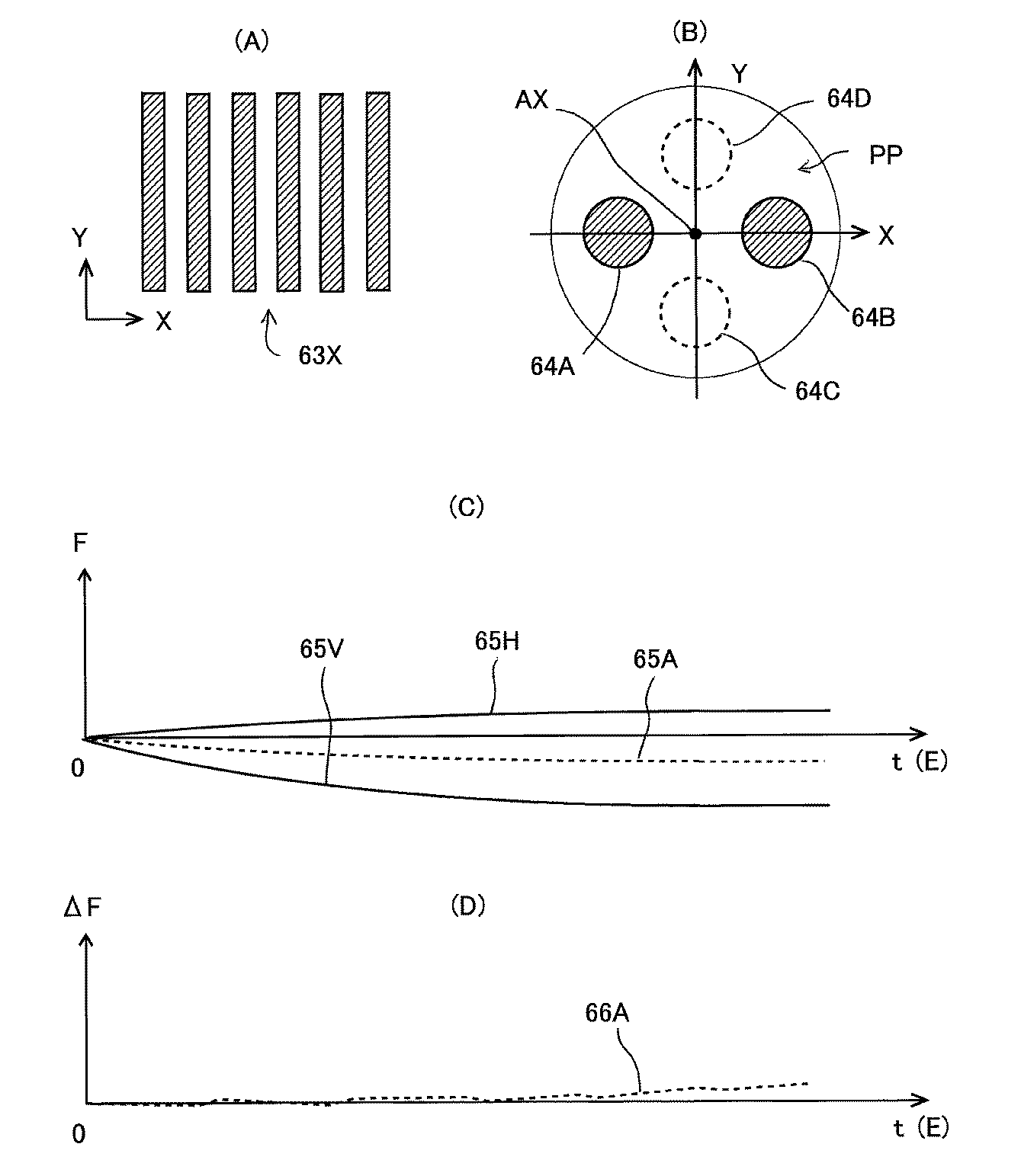
また、例えばレチクルRのパターンが図6(A)に示すX方向に微細ピッチのL&Sパターン63Xを含む場合には、一例として照明条件がX方向の2極照明に設定され、投影光学系PLの瞳面PPにおける光量分布は、図6(B)に示すように、光軸AXをX方向に挟む領域64A,64Bで大きい分布となる。その結果、露光開始後の時間tに応じて、X方向及びY方向のL&Sパターンの像のベストフォーカス位置はそれぞれ図6(C)の曲線65V及び65Hで示すように変化して、その平均的なベストフォーカス位置は点線の曲線65Aで示すように変化する。
For example, when the pattern of the reticle R includes the L &
言い換えると、このような場合には、補正対象の収差Biのうちでフォーカス(ベストフォーカス位置)が大きい影響を持つことになる。この場合には、特にフォーカスの計測に重点を置き、図2の光ガイド42A,42B等からレンズエレメントに非露光光を照射する結像特性調整を行うことによって、図6(D)の点線の曲線66Aに示すように、フォーカスの残差ΔFを小さくできる。
In other words, in such a case, the focus (best focus position) has a large influence among the aberration Bi to be corrected. In this case, with particular emphasis on focus measurement, by adjusting the imaging characteristics of irradiating the lens element with non-exposure light from the light guides 42A and 42B in FIG. 2, the dotted line in FIG. As indicated by a
以下、本実施形態の図1の露光装置100において例えばそれまでに使用したことのないレチクルRを用いて、対応する露光条件(照明条件、投影光学系PLの開口数、照射量)で、数ロットのウエハに露光を行う場合の動作の一例につき図7(A)のフローチャートを参照して説明する。
先ず、図7(A)のステップ101において、図2に示すようにレチクルステージRST上に計測用のレチクル27をロードし、その上方に拡散板38を設置して、計測ステージMSTの波面収差計測装置21を用いて、投影光学系PLの像の収差(ツェルニケ多項式の係数)Z1〜Z37で表される波面収差を計測し、計測結果を図4の主制御装置20及び結像特性予測部56を介して結像特性制御系78に供給する。この計測時に、図1のウエハステージWSTはローディング位置に移動して、図7(A)のステップ111において、ウエハステージWST上にウエハW(ここでは1枚目のウエハ)がロードされる。このウエハWには、不図示のレジストのコータ・デベロッパにおいてレジストが塗布されている(ステップ121)。
In the following, in the
First, in
ステップ101に続くステップ102において、結像特性制御系78によって図2の結像特性制御機構を用いて、投影光学系PLの波面収差中の補正対象の全部の結像特性、即ち式(1)の収差Bj(j=1〜p)が全部0になるように補正する。これとほぼ同時に、レチクルステージRST上にレチクルRをロードし、拡散板38を退避させた後、レチクルRのアライメントを行う。そして、ステップ102及びステップ111に続くステップ103において、図1に示すように、投影光学系PLの下方にウエハステージWSTが移動して、図2のアライメント系ALGを用いてウエハWのアライメントが行われる。次に、図1のインテグレータセンサ4によって露光光ILの照射量を計測しながら、1枚のウエハの露光を行う。具体的に、図1のウエハステージWSTをX方向、Y方向に駆動して、ウエハWが走査開始位置にステップ移動される。続いて、投影光学系PLとウエハWとの間への液体Lqの供給を開始し、露光光ILの照射を開始して、レチクルステージRSTを介してY方向にレチクルRを走査するのに同期して、ウエハステージWSTを介して投影光学系PLの露光領域に対してウエハW上の一つのショット領域を対応する方向に投影倍率を速度比として走査する走査露光が行われる。そのステップ移動と走査露光とを繰り返すステップ・アンド・スキャン動作によって、ウエハW上の各ショット領域にレチクルRのパターンの像が転写される。
In
また、この1枚のウエハWの露光中に、インテグレータセンサ4で計測される露光光ILの照射量、及び図4の照射パラメータ記憶部54に記憶されている照射パラメータを用いて例えば式(4)等から結像特性予測部56が収差Bj(j=1〜p)の変動量を所定の計算周期で予測する。そして、予測される収差Bjの変動量をそれぞれ0にする(補正する)ように結像特性制御系78によって結像特性制御機構が駆動される。
Further, using the irradiation parameter stored in the irradiation parameter storage unit 54 of FIG. 4 using, for example, the equation (4) using the irradiation amount of the exposure light IL measured by the integrator sensor 4 during the exposure of the single wafer W. ) And the like, the imaging characteristic prediction unit 56 predicts the fluctuation amount of the aberration Bj (j = 1 to p) in a predetermined calculation cycle. Then, the imaging
その後、ウエハステージWSTの動作はステップ112に移行してウエハのアンローDが行われた後、ステップ108に移行する。一方、計測ステージMSTは、ステップ103に続くステップ104において、投影光学系PLの下方に移動する。そして、図3(A)に示すように、レチクルステージRSTを駆動して計測用基準板RFMを露光光ILの照明領域に移動した後、計測ステージMSTの空間像計測系45を用いて計測用基準板RFMの所定の位置の所定の評価用マークPMの像を計測する。そして、上記の収差Bjの一部である、投影光学系PLの球面収差、ディストーション、フォーカス、及び倍率(ディストーションの一部)の結像特性を計測し、計測結果及び照射量の情報を図4の照射パラメータ演算部55に供給する。照射パラメータ演算部55には、結像特性予測部56から現在の収差Bjの予測値(即ち、結像特性制御機構による補正量)の情報も供給されている。なお、ステップ104で計測される結像特性は、レチクルR及び露光条件によって変化する。具体的に、レチクルRのパターンの像に大きい影響を与えると予想される結像特性が計測される。また、ステップ104〜108の動作は、例えばウエハが所定の複数枚露光される毎に行うようにしてもよい。
Thereafter, the operation of wafer stage WST proceeds to step 112, and after wafer unloading D is performed, the operation proceeds to step 108. On the other hand, measurement stage MST moves below projection optical system PL in
次のステップ105において、照射パラメータ演算部55は、空間像計測系45によって計測された結像特性に適合するように対応する球面収差、ディストーション、フォーカス、及び倍率の照射パラメータの値を計算する。ディストーションDiの場合には、計測値は図5の点線の曲線61Mの残差ΔDiであり、計算される照射パラメータは、図5(A)の実線の曲線60Rの飽和ディストーション(Sdm/照度)及び時定数Tdmである。なお、このステップ105の照射パラメータの計算は、ステップ104の結像特性の計測を所定の複数回行う毎に、例えばその計測結果の平均値に基づいて行うようにしてもよい。
In the
次のステップ106において、照射パラメータ演算部55は、計算された照射パラメータの値と照射パラメータ記憶部54に記憶されている照射パラメータの値とを比較して、計算された照射パラメータの変化量が許容範囲を超えたかどうかを判定する。そして、その変化量が許容範囲を超えた照射パラメータがある場合には、ステップ107に移行して、変化量が許容範囲を超えた照射パラメータについては、照射パラメータ記憶部54内に記憶されている値を更新し、変化量が許容範囲を超えていない照射パラメータについては更新を行わない。次にステップ108に移行する。一方、ステップ106で、変化量が許容範囲を超えた照射パラメータがない場合には、そのままステップ108に移行する。
In the
そして、露光すべきウエハが残っている場合には、ウエハステージWSTはステップ111に移行して次のウエハのロードを行う。また、計測ステージMSTはステップ103に移行して、投影光学系PLの下方から退避する。その後、ステップ103〜108のウエハの露光(更新された照射パラメータを用いて予測される収差の補正が行われる)、所定の結像特性の照射パラメータの計測及び必要に応じた更新が繰り返される。
If a wafer to be exposed remains, wafer stage WST moves to step 111 to load the next wafer. Further, the measurement stage MST moves to step 103 and retreats from below the projection optical system PL. Thereafter, exposure of the wafer in
そして、例えば1ロットのウエハが終了した後には、ステップ104の代わりに、図7(B)のステップ104Aにおいて、更に計測対象の結像特性を減少させて、図3(A)の空間像計測系45を用いてフォーカス、倍率のみを計測してもよい。この場合には、それに続くステップ105においては、ステップ104Aで計測されたフォーカス、倍率のみの照射パラメータの値が計算される。これは、1ロットの露光中の計測によって、その他の結像特性(ここでは球面収差、ディストーション(倍率を除く))については、照射パラメータがほぼ正確に求められたとみなされるからである。従って、レチクルRのパターン及び/又は露光条件によっては、ステップ104Aにおいても、球面収差等の計測を行ってもよい。
For example, after the completion of one lot of wafers, instead of
そして、ステップ108において、露光対象のウエハが尽きたときに露光工程が終了する。また、ステップ112でアンロードされた露光済みのウエハWは、露光装置100からコータ・デベロッパ(不図示)に搬送され、ステップ122においてウエハのレジストの現像が行われる。次のステップ123において、現像したウエハの加熱(キュア)、エッチング工程などを含む基板処理が行われる。そして、次のステップ124において、必要に応じてリソグラフィ工程及び基板処理工程を繰り返した後、デバイス組み立てステップ(ダイシング工程、ボンディング工程、パッケージ工程などの加工プロセスを含む)、及び検査ステップ等を経て半導体デバイス等のデバイスが製造される。この際に、本実施形態のウエハ上には、必要な結像特性が必要な精度内に維持されて露光が行われるため、予め図4の照射パラメータ記憶部54に各種の照射パラメータの値を記憶しておくことなく、高精度にデバイスを製造できる。
In
また、露光工程の最後に計算された照射パラメータの値は、レチクルRのパターン及び露光条件に対応して露光データとして記憶される。そして、次に同じレチクルRを同じ露光条件で露光する場合には、照射パラメータとしてその記憶してある値が使用される。そして、図7(A)のステップ104においては、始めから図7(B)のステップ104Aと同様に、計測対象の結像特性を必要最小限にすることで、露光精度を低下させることなく、露光工程のスループットを向上できる。
The value of the irradiation parameter calculated at the end of the exposure process is stored as exposure data corresponding to the pattern of the reticle R and the exposure conditions. Next, when the same reticle R is exposed under the same exposure conditions, the stored value is used as an irradiation parameter. Then, in
本実施形態の作用効果等は以下の通りである。
(1)上記の実施形態の露光装置100の結像特性(光学特性)調整方法は、露光光を用いてレチクルRのパターン(所定のパターン)の像を投影光学系PL(光学系)を介してウエハW上に形成する際の投影光学系PLの結像特性(光学特性)の調整方法であって、投影光学系PLの複数の収差Bj(j=1〜p)を含む複数の結像特性(収差Z1〜Z37で表される波面収差)を計測するステップ101(第1計測工程)と、ステップ101の計測結果に基づいて、複数の収差Bjを調整するステップ102(第1調整工程)とを有する。さらにその調整方法は、その複数の収差Bjが調整された投影光学系PLを介して、レチクルRのパターンの像をウエハW上に形成した後、その複数の収差Bjのうちの球面収差、ディストーション(倍率を含む)、及びフォーカス(第1組の結像特性)を計測するステップ104(第2計測工程)と、その投影光学系PLによる露光光ILの照射量の情報及びそのステップ104の計測結果を用いて、その第1組の結像特性の変動量を予測するための照射パラメータ(第1のパラメータ情報)を求めるステップ105(算出工程)とを有する。
Effects and the like of this embodiment are as follows.
(1) The image formation characteristic (optical characteristic) adjustment method of the
従って、予め様々な条件のもとで投影光学系PLの結像特性の変動量の正確な予測モデルを求めて記憶しておくことなく、実際に使用される条件のもとで投影光学系PLの結像特性の変動量を正確に予測できる。また、始めに複数の収差Bjの補正を行っておくことによって、計測対象以外の結像特性が像に与える影響を小さくできる。
(2)また、ステップ102の後に、露光光ILの照射量を考慮して複数の収差Bjのの変動量を予測するための照射パラメータの初期値又は更新前の値(第2のパラメータ情報)と、露光光ILの照射量の計測情報とに基づいて、複数の収差Bjを調整するステップ103(第2調整工程)を有する。従って、露光中に照射量に応じて変動する結像特性を補正できる。
Therefore, the projection optical system PL can be used under the conditions actually used without obtaining and storing in advance an accurate prediction model of the variation amount of the imaging characteristics of the projection optical system PL under various conditions. It is possible to accurately predict the fluctuation amount of the imaging characteristics. Further, by first correcting the plurality of aberrations Bj, the influence of the imaging characteristics other than the measurement target on the image can be reduced.
(2) After
(3)また、ステップ105では、露光光ILの照射量の計測値と、ステップ103で用いられた照射パラメータの初期値(又は更新前の値)から予測される結像特性の調整量を計測される結像特性から差し引いて照射パラメータを求めている。従って、結像特性制御機構によって結像特性の補正を行いつつ、変動後の結像特性の照射パラメータを高精度に求めることができる。
(3) In
(4)また、ステップ103でその第1組の結像特性が調整された投影光学系PLを介してレチクルRのパターンの像をウエハW上に形成した後、第1組の結像特性のうち、フォーカス、倍率(第2組の結像特性)を計測するステップ104A(第3計測工程)を有し、そのステップ105では、投影光学系PLにおける露光光ILの照射量の計測値に基づいて、その第2組の結像特性の変動量を予測するための照射パラメータ(第3のパラメータ情報)を求める。これによって、照射パラメータが高精度に求められている結像特性については、その計測を省略してスループットを向上できる。
(4) Further, after forming an image of the pattern of the reticle R on the wafer W via the projection optical system PL in which the first set of imaging characteristics is adjusted in
(5)また、そのステップ104で計測される第1組の結像特性は、一例として、露光光の照射による変動量が、その複数の収差Bjの中の他の結像特性の変動量よりも大きいものであることが好ましい。
(6)また、その第1組の結像特性は、別の例として、露光光の照射による変動によってレチクルRのパターンの像の形成誤差に与える影響が、その複数の収差Bj中の他の結像特性が与える影響よりも大きいものであることが好ましい。
(5) Further, as an example, the first set of imaging characteristics measured in
(6) Further, as another example, the imaging characteristics of the first set of the first set of imaging characteristics are affected by the variation in the pattern of the reticle R caused by the exposure light irradiation. It is preferable that the influence is greater than the influence of the imaging characteristics.
これによって、計測対象の結像特性を減少させながら、高精度に露光を行うことができる。
(7)また、図7(A)のステップ101においては、投影光学系PLの収差Z1〜Z37で表される投影光学系PLの波面収差を計測している。そして、ステップ104で計測する第1組の結像特性は、その波面収差中の、球面収差、コマ収差、ディストーション、倍率誤差、及びフォーカス(デフォーカス)のうちの少なくとも2つを含むことが好ましい。これによって、計測効率を高めることができる。
This makes it possible to perform exposure with high accuracy while reducing the imaging characteristics of the measurement target.
(7) In
(8)また、計測対象の波面収差は収差Z1〜Z37で表されるため、例えば高次の収差の補正も可能である。なお、例えば低次及び中次の収差のみを補正する場合には、収差Z1〜Z16で表される波面収差のみを計測してもよい。さらに、波面収差中で、実際に補正されるp個の収差Bj(j=1〜p)に対応する収差のみを計測してもよい。
(9)また、図2の結像特性制御機構は、投影光学系PLのレンズエレメントの姿勢の制御、及び所定のレンズエレメントの加熱を行っている。しかしながら、その結像特性制御機構は、例えばステップ102で投影光学系PLの複数の収差Bjを調整する際に、投影光学系PLを構成する光学部材の姿勢制御、投影光学系PLの光軸方向におけるウエハW又はレチクルRの位置制御、レチクルRの加熱、投影光学系PLを構成する光学部材の加熱、及び投影光学系PLを構成する光学部材の変形のうちの少なくとも一つを実行するのみでもよい。なお、結像特性制御機構による駆動の自由度は、補正対象の結像特性の個数以上に設定されることが好ましい。
(8) Since the wavefront aberration to be measured is represented by the aberrations Z1 to Z37, for example, higher-order aberrations can be corrected. For example, when only low-order and medium-order aberrations are corrected, only the wavefront aberrations represented by the aberrations Z1 to Z16 may be measured. Further, only the aberration corresponding to the p aberrations Bj (j = 1 to p) actually corrected in the wavefront aberration may be measured.
(9) Further, the imaging characteristic control mechanism in FIG. 2 controls the posture of the lens element of the projection optical system PL and heats a predetermined lens element. However, the image formation characteristic control mechanism, for example, when adjusting a plurality of aberrations Bj of the projection optical system PL in
(10)また、上記の実施形態の露光装置100による露光方法は、露光光ILを用いてレチクルRのパターンの像を投影光学系PLを介してウエハW上に形成する露光方法において、上記の結像特性調整方法を用いて求められた照射パラメータの情報と、ウエハW上における露光光ILの照射量とに基づいて、投影光学系PLのその第1組の結像特性を調整しながら、レチクルRのパターンの像をウエハW上に形成するステップ103(形成工程)を有する。
(10) The exposure method using the
従って、その第1組の結像特性を所定の許容範囲内に高精度に追い込むことができ、レチクルRのパターンを高精度にウエハW上に露光できる。
(11)また、上記の実施形態のデバイス製造方法は、その露光方法を用いて投影光学系PLの像面上に設置されるウエハW(基板)を露光すること(ステップ103)と、露光されたウエハWを処理すること(ステップ122、123)とを含むものである。これによって、種々のパターンをそれぞれ高精度に基板上に露光できるため、種々のパターンが複数層に形成されるデバイスを高精度に製造できる。
Therefore, the first set of imaging characteristics can be driven within a predetermined allowable range with high accuracy, and the pattern of the reticle R can be exposed onto the wafer W with high accuracy.
(11) In the device manufacturing method of the above embodiment, the exposure method is used to expose the wafer W (substrate) placed on the image plane of the projection optical system PL (step 103), and the exposure is performed. Processing the wafer W (
なお、上記の実施形態では、投影光学系PLを光学系とみなしている。しかしながら、図8(A)に示すように、透過率ηR のレチクルR及び透過率ηPLの投影光学系PLを全体として一つの光学系とみなすことも可能である。レチクルRの透過率ηR は、例えばレチクルRの無い場合と有る場合とで、図2の照射量モニタ35によって露光光ILの照度を計測することによって求めることができ、投影光学系PLの透過率ηPLは、例えばレチクルRが無いときの図1のインテグレータセンサ4の計測値、照射量モニタ35の計測値、及び照明光学系の既知の透過率から求めることができる。
In the above embodiment, the projection optical system PL is regarded as an optical system. However, as shown in FIG. 8 (A), it is also possible to regard the one optical system of the projection optical system PL the reticle R and the transmittance eta PL transmittance eta R as a whole. The transmittance η R of the reticle R can be obtained, for example, by measuring the illuminance of the exposure light IL with the dose monitor 35 of FIG. 2 depending on whether the reticle R is not present or not, and is transmitted through the projection optical system PL. The rate η PL can be obtained from, for example, the measured value of the integrator sensor 4 in FIG. 1 when there is no reticle R, the measured value of the
この場合には、例えばディストーションDiを例に取ると、式(4)の代わりに例えば次の式からディストーションDiを計算できる。
Di=Sdiuni×PPL×[1−exp(-t/Tdi)]
+SdRuni×PR×[1−exp(-t/TdR)] …(5)
この式において、PPL及びPR は、図8(A)の投影光学系PLの像面(ウエハ面)及びレチクルRの底面での照度であり、SdRuni はレチクルRにおける単位照度当たりの飽和ディストーション、TdRはレチクルRにおける時定数である。照射パラメータは、Sdiuni、SdRuni、Tdi、TdRの4つとなる。
In this case, for example, when the distortion Di is taken as an example, the distortion Di can be calculated from, for example, the following equation instead of the equation (4).
Di = Sdiuni × P PL × [1-exp (−t / Tdi)]
+ SdRuni × P R × [1-exp (−t / TdR)] (5)
In this formula, P PL and P R are the illuminance on the image plane (wafer plane) and the bottom surface of the reticle R in the projection optical system PL in FIG. 8 (A), SdRuni saturated distortion per unit illuminance on the reticle R , TdR is a time constant in the reticle R. There are four irradiation parameters: Sdiuni, SdRuni, Tdi, and TdR.
この場合、レチクルRの露光光ILの吸収量ΔERと、投影光学系PLの露光光ILの吸収量ΔEPLとの比は次のようになる。
ΔER:ΔEPL=(1−ηR):ηR(1−ηPL) …(6)
従って、結像特性の変動に与えるレチクルRの影響EFRの割合は、次のようになる。
EFR=ΔER/(ΔER+ΔEPL) …(7)
この影響EFRは、レチクルRの透過率ηR に対して図8(B)のようにほぼ反比例して変化する。従って、レチクルRの透過率ηR が小さい場合には、レチクルRの影響EFRが大きくなるため、式(5)のようにレチクルRの寄与を考慮することが特に有効となる。
In this case, the ratio between the exposure light IL absorption amount ΔER of the reticle R and the exposure light IL absorption amount ΔEPL of the projection optical system PL is as follows.
ΔER: ΔEPL = (1-η R ): η R (1-η PL ) (6)
Accordingly, the ratio of the influence EFR of the reticle R on the fluctuation of the imaging characteristics is as follows.
EFR = ΔER / (ΔER + ΔEPL) (7)
This effect EFR changes in inverse proportion to the transmittance η R of the reticle R as shown in FIG. Therefore, when the transmittance η R of the reticle R is small, the influence EFR of the reticle R becomes large, so that it is particularly effective to consider the contribution of the reticle R as shown in equation (5).
なお、本発明は、上記の波面収差計測装置21及び/又は空間像計測系45がウエハステージWST内に装着されている露光装置で露光する場合にも適用可能である。また、本発明は、上述のステップ・アンド・スキャン方式の走査露光型の投影露光装置(スキャナ)の他に、ステップ・アンド・リピート方式の投影露光装置(ステッパ等)で露光する場合にも適用できる。さらに、本発明は、液浸型露光装置以外の、ドライ露光型の露光装置で露光する場合にも同様に適用することができる。
The present invention can also be applied to the case where the above-described wavefront
また、本発明は、半導体デバイス製造用の露光装置への適用に限定されることなく、例えば、角型のガラスプレートに形成される液晶表示素子、若しくはプラズマディスプレイ等のディスプレイ装置用の露光装置や、撮像素子(CCD等)、マイクロマシーン、薄膜磁気ヘッド、及びDNAチップ等の各種デバイスを製造するための露光装置にも広く適用できる。更に、本発明は、各種デバイスのマスクパターンが形成されたマスク(フォトマスク、レチクル等)をフォトリソグラフィ工程を用いて製造する際の、露光工程(露光装置)にも適用することができる。 In addition, the present invention is not limited to application to an exposure apparatus for manufacturing a semiconductor device, for example, an exposure apparatus for a display device such as a liquid crystal display element formed on a square glass plate or a plasma display, It can also be widely applied to an exposure apparatus for manufacturing various devices such as an image sensor (CCD or the like), a micromachine, a thin film magnetic head, and a DNA chip. Furthermore, the present invention can also be applied to an exposure process (exposure apparatus) when manufacturing a mask (photomask, reticle, etc.) on which mask patterns of various devices are formed using a photolithography process.
なお、本発明は上述の実施形態に限定されず、本発明の要旨を逸脱しない範囲で種々の構成を取り得る。 In addition, this invention is not limited to the above-mentioned embodiment, A various structure can be taken in the range which does not deviate from the summary of this invention.
10…照明系、R…レチクル、RFM…計測用基準板、PL…投影光学系、W…ウエハ、WST…ウエハステージ、MST…計測ステージ、14A,14B…駆動素子、19…AF系、20…主制御装置、21…波面収差計測装置、22…標示板、42A,42B…光ガイド、45…空間像計測系、78…結像特性制御系
DESCRIPTION OF
Claims (11)
前記光学系の複数の光学特性を計測する第1計測工程と;
前記第1計測工程の計測結果に基づいて、前記複数の光学特性を調整する第1調整工程と;
前記複数の光学特性が調整された前記光学系を介して、前記所定のパターンの像を前記物体上に形成した後、前記複数の光学特性のうち、第1組の光学特性を計測する第2計測工程と;
前記光学系における前記露光光の照射量に関する情報に基づいて、前記第1組の光学特性の変動量を予測するための第1のパラメータ情報を求める算出工程と;
を有することを特徴とする光学特性調整方法。 A method for adjusting the optical characteristics of an optical system that forms an image of a predetermined pattern on an object using exposure light,
A first measurement step of measuring a plurality of optical characteristics of the optical system;
A first adjustment step of adjusting the plurality of optical characteristics based on a measurement result of the first measurement step;
A second set of measuring a first set of optical characteristics among the plurality of optical characteristics after forming an image of the predetermined pattern on the object via the optical system in which the plurality of optical characteristics are adjusted; Measuring process;
A calculation step of obtaining first parameter information for predicting a fluctuation amount of the first set of optical characteristics based on information on the exposure light dose in the optical system;
A method for adjusting optical characteristics, comprising:
前記算出工程は、前記光学系における前記露光光の照射量に関する情報に基づいて、前記第2組の光学特性の変動量を予測するための第3のパラメータ情報を求めることを特徴とする請求項1に記載の光学特性調整方法。 After forming the image of the predetermined pattern on the object through the optical system in which the first set of optical characteristics is adjusted, the second set of optical characteristics is measured among the first set of optical characteristics. A third measuring step to
The calculation step is characterized in that third parameter information for predicting a variation amount of the second set of optical characteristics is obtained based on information related to an irradiation amount of the exposure light in the optical system. 2. The optical property adjusting method according to 1.
前記第2計測工程で計測する前記第1組の光学特性は、前記光学系の球面収差、コマ収差、ディストーション、倍率誤差、及びデフォーカスのうちの少なくとも2つを含むことを特徴とする請求項1から請求項6のいずれか一項に記載の光学特性調整方法。 The plurality of optical characteristics measured in the first measurement step include a wavefront aberration of the optical system,
The first set of optical characteristics measured in the second measurement step includes at least two of spherical aberration, coma aberration, distortion, magnification error, and defocus of the optical system. The optical characteristic adjustment method according to any one of claims 1 to 6.
請求項1から請求項9のいずれか一項に記載の光学特性調整方法を用いて求められた前記第1のパラメータ情報と、前記物体上における前記露光光の照射量とに基づいて、前記光学系の前記第1組の光学特性を調整しながら、前記所定のパターンの像を前記物体上に形成する形成工程を有することを特徴とする露光方法。 In an exposure method for forming an image of a predetermined pattern on an object via an optical system using exposure light,
Based on the first parameter information obtained by using the optical characteristic adjustment method according to any one of claims 1 to 9, and the exposure light irradiation amount on the object, the optical An exposure method comprising: forming an image of the predetermined pattern on the object while adjusting the first set of optical characteristics of the system.
前記露光された基板を処理することと、を含むデバイス製造方法。 Exposing a substrate placed on the image plane of the projection optical system using the exposure method according to claim 10;
Processing the exposed substrate. A device manufacturing method comprising:
Priority Applications (1)
| Application Number | Priority Date | Filing Date | Title |
|---|---|---|---|
| JP2008046453A JP2009206274A (en) | 2008-02-27 | 2008-02-27 | Optical characteristics adjusting method, exposure method, and manufacturing method of device |
Applications Claiming Priority (1)
| Application Number | Priority Date | Filing Date | Title |
|---|---|---|---|
| JP2008046453A JP2009206274A (en) | 2008-02-27 | 2008-02-27 | Optical characteristics adjusting method, exposure method, and manufacturing method of device |
Publications (1)
| Publication Number | Publication Date |
|---|---|
| JP2009206274A true JP2009206274A (en) | 2009-09-10 |
Family
ID=41148259
Family Applications (1)
| Application Number | Title | Priority Date | Filing Date |
|---|---|---|---|
| JP2008046453A Withdrawn JP2009206274A (en) | 2008-02-27 | 2008-02-27 | Optical characteristics adjusting method, exposure method, and manufacturing method of device |
Country Status (1)
| Country | Link |
|---|---|
| JP (1) | JP2009206274A (en) |
Cited By (2)
| Publication number | Priority date | Publication date | Assignee | Title |
|---|---|---|---|---|
| JP2019164351A (en) * | 2012-02-20 | 2019-09-26 | カール・ツァイス・エスエムティー・ゲーエムベーハー | Projection exposure method and projection exposure apparatus for microlithography |
| CN113218624A (en) * | 2020-01-21 | 2021-08-06 | 三星显示有限公司 | Optical measuring device |
-
2008
- 2008-02-27 JP JP2008046453A patent/JP2009206274A/en not_active Withdrawn
Cited By (3)
| Publication number | Priority date | Publication date | Assignee | Title |
|---|---|---|---|---|
| JP2019164351A (en) * | 2012-02-20 | 2019-09-26 | カール・ツァイス・エスエムティー・ゲーエムベーハー | Projection exposure method and projection exposure apparatus for microlithography |
| JP7090375B2 (en) | 2012-02-20 | 2022-06-24 | カール・ツァイス・エスエムティー・ゲーエムベーハー | Projection exposure method and projection exposure equipment for microlithography |
| CN113218624A (en) * | 2020-01-21 | 2021-08-06 | 三星显示有限公司 | Optical measuring device |
Similar Documents
| Publication | Publication Date | Title |
|---|---|---|
| US7667829B2 (en) | Optical property measurement apparatus and optical property measurement method, exposure apparatus and exposure method, and device manufacturing method | |
| US7965387B2 (en) | Image plane measurement method, exposure method, device manufacturing method, and exposure apparatus | |
| JP4345098B2 (en) | Exposure apparatus, exposure method, and device manufacturing method | |
| EP1347501A1 (en) | Wavefront aberration measuring instrument, wavefront aberration measuring method, exposure apparatus, and method for manufacturing microdevice | |
| JP2005175034A (en) | Exposure equipment | |
| JPWO2008132799A1 (en) | Measuring method, exposure method, and device manufacturing method | |
| KR20070094543A (en) | Exposure apparatus and image detection method | |
| JP4692862B2 (en) | Inspection apparatus, exposure apparatus provided with the inspection apparatus, and method for manufacturing microdevice | |
| JP2005311020A (en) | Exposure method and device manufacturing method | |
| JP5489849B2 (en) | Position measuring apparatus and method, exposure apparatus and device manufacturing method | |
| US7498596B2 (en) | Exposure method that obtains, prior to exposure, reticle surface form data and measurement position error, for scanning control | |
| JP3762323B2 (en) | Exposure equipment | |
| US7385672B2 (en) | Exposure apparatus and method | |
| US8345221B2 (en) | Aberration measurement method, exposure apparatus, and device manufacturing method | |
| JP2001250760A (en) | Aberration measurement method, mark detection method using the method, and exposure method | |
| JP2005302825A (en) | Exposure system | |
| WO2002050506A1 (en) | Wavefront measuring apparatus and its usage, method and apparatus for determining focusing characteristics, method and apparatus for correcting focusing characteristics, method for managing focusing characteristics, and method and apparatus for exposure | |
| US7221434B2 (en) | Exposure method and apparatus | |
| US20010046041A1 (en) | Exposure apparatus and device manufacturing apparatus and method | |
| JP4147574B2 (en) | Wavefront aberration measurement method, projection optical system adjustment method and exposure method, and exposure apparatus manufacturing method | |
| JP2011009411A (en) | Optical characteristic measuring method, exposure method, and device manufacturing method | |
| JP2009206274A (en) | Optical characteristics adjusting method, exposure method, and manufacturing method of device | |
| JP2006279029A (en) | Exposure method and apparatus | |
| WO2013094733A1 (en) | Measurement method and device, and maintenance method and device | |
| KR20110026383A (en) | Exposure apparatus, exposure method, and device manufacturing method using the same |
Legal Events
| Date | Code | Title | Description |
|---|---|---|---|
| A300 | Withdrawal of application because of no request for examination |
Free format text: JAPANESE INTERMEDIATE CODE: A300 Effective date: 20110510 |