JP2010125987A - Hybrid propulsion unit for marine vessel - Google Patents
Hybrid propulsion unit for marine vessel Download PDFInfo
- Publication number
- JP2010125987A JP2010125987A JP2008302696A JP2008302696A JP2010125987A JP 2010125987 A JP2010125987 A JP 2010125987A JP 2008302696 A JP2008302696 A JP 2008302696A JP 2008302696 A JP2008302696 A JP 2008302696A JP 2010125987 A JP2010125987 A JP 2010125987A
- Authority
- JP
- Japan
- Prior art keywords
- rotation speed
- pitch propeller
- propulsion
- variable pitch
- power
- Prior art date
- Legal status (The legal status is an assumption and is not a legal conclusion. Google has not performed a legal analysis and makes no representation as to the accuracy of the status listed.)
- Granted
Links
- 238000004364 calculation method Methods 0.000 claims description 8
- 238000001514 detection method Methods 0.000 claims description 4
- 230000001141 propulsive effect Effects 0.000 abstract description 34
- 239000000446 fuel Substances 0.000 abstract description 15
- 238000010586 diagram Methods 0.000 description 13
- 230000007935 neutral effect Effects 0.000 description 8
- 230000004044 response Effects 0.000 description 6
- 230000004043 responsiveness Effects 0.000 description 6
- 230000007704 transition Effects 0.000 description 4
- 230000003111 delayed effect Effects 0.000 description 2
- 238000013459 approach Methods 0.000 description 1
- 230000000694 effects Effects 0.000 description 1
- 238000012886 linear function Methods 0.000 description 1
- 238000000034 method Methods 0.000 description 1
Images


Classifications
-
- Y—GENERAL TAGGING OF NEW TECHNOLOGICAL DEVELOPMENTS; GENERAL TAGGING OF CROSS-SECTIONAL TECHNOLOGIES SPANNING OVER SEVERAL SECTIONS OF THE IPC; TECHNICAL SUBJECTS COVERED BY FORMER USPC CROSS-REFERENCE ART COLLECTIONS [XRACs] AND DIGESTS
- Y02—TECHNOLOGIES OR APPLICATIONS FOR MITIGATION OR ADAPTATION AGAINST CLIMATE CHANGE
- Y02T—CLIMATE CHANGE MITIGATION TECHNOLOGIES RELATED TO TRANSPORTATION
- Y02T70/00—Maritime or waterways transport
- Y02T70/50—Measures to reduce greenhouse gas emissions related to the propulsion system
- Y02T70/5218—Less carbon-intensive fuels, e.g. natural gas, biofuels
- Y02T70/5236—Renewable or hybrid-electric solutions
Landscapes
- Control Of Vehicle Engines Or Engines For Specific Uses (AREA)
Abstract
【課題】1つの推進レバーの操作で主機に駆動される可変ピッチプロペラと電動機で駆動される固定ピッチプロペラとの推進力の最適な分担が行え、かつ、船舶の運行時の燃費を向上することができる船舶用ハイブリッド推進装置を提供する。
【解決手段】主機1で可変ピッチプロペラ2を回転させる推進装置と、補機原動機12で駆動される発電機11で発電して電動機14で固定ピッチプロペラを駆動させる電気推進装置とを備えた船舶用ハイブリッド推進装置において、1つの操作レバー5で主機1の回転速度基準および可変ピッチプロペラ2の角度を設定し、主機1の回転軸で検出された馬力から電動機14の入力電力基準を決定し、この電動機14の入力電力基準値と実際の入力電力が一致するように電力制御を行って電動機14の回転速度を決定し、この決定された回転速度で固定ピッチプロペラ15を駆動させる。
【選択図】図1An object of the present invention is to optimally share the propulsive force between a variable pitch propeller driven by a main propeller by operation of one propulsion lever and a fixed pitch propeller driven by an electric motor, and to improve fuel efficiency during ship operation. Provided is a marine hybrid propulsion device capable of
A marine vessel provided with a propulsion device for rotating a variable pitch propeller (2) by a main engine (1) and an electric propulsion device for generating electric power by a generator (11) driven by an auxiliary motor (12) and driving a fixed pitch propeller by an electric motor (14). In the hybrid propulsion apparatus, the rotational speed reference of the main engine 1 and the angle of the variable pitch propeller 2 are set by one operating lever 5, and the input power reference of the electric motor 14 is determined from the horsepower detected by the rotation shaft of the main engine 1. Power control is performed so that the input power reference value of the electric motor 14 and the actual input electric power coincide with each other, the rotational speed of the electric motor 14 is determined, and the fixed pitch propeller 15 is driven at the determined rotational speed.
[Selection] Figure 1
Description
本発明は、ディーゼルエンジン等の主機(原動機)で推進用プロペラを回転させる推進装置と、補機原動機で駆動される発電機で発電して電動機で推進用プロペラを駆動させる電気推進装置とを備えた船舶用ハイブリッド推進装置に関する。 The present invention includes a propulsion device that rotates a propeller for propulsion by a main engine (primary motor) such as a diesel engine, and an electric propulsion device that generates electric power by a generator driven by an auxiliary motor and drives the propeller for propulsion by an electric motor. The present invention relates to a marine hybrid propulsion device.
推進用プロペラの推進効率を向上させるために、船体の船尾下部に二重反転型プロペラを設置した船舶がある(例えば、特許文献1参照)。
二重反転型プロペラは、推進方向側に配置された前プロペラと、推進方向と反対側に配置された後プロペラから成り、前プロペラと後プロペラを同一軸線上に配置し、後プロペラを前プロペラの回転方向と逆方向に回転させることで、前プロペラで生じる回転流のエネルギーを後プロペラで回収することができ、高い効率が得られる。
In order to improve the propulsion efficiency of the propeller for propulsion, there is a ship in which a counter-rotating propeller is installed at the bottom of the stern of the hull (see, for example, Patent Document 1).
The contra-rotating propeller includes a front propeller disposed on the propulsion direction side and a rear propeller disposed on the opposite side to the propulsion direction. The front propeller and the rear propeller are disposed on the same axis, and the rear propeller is disposed on the front propeller. By rotating in the direction opposite to the rotation direction, the energy of the rotating flow generated by the front propeller can be recovered by the rear propeller, and high efficiency can be obtained.
以下、図8の制御回路図を参照して二重反転型プロペラを駆動する従来の船舶用ハイブリッド推進装置について説明する。
先ず、主機で推進用プロペラを回転させる推進装置の構成から説明する。
Hereinafter, a conventional marine hybrid propulsion device for driving a counter rotating type propeller will be described with reference to a control circuit diagram of FIG.
First, the structure of the propulsion device that rotates the propeller for propulsion in the main machine will be described.
1は主機原動機(以下、主機という)であり、2は主機1の主機軸8により直接駆動される可変ピッチプロペラである。3は後述する翼角設定器4から出力される翼角信号により前記可変ピッチプロペラ2の翼角を調整する変節装置である。
5は操船者によって操作(操縦)され、その操作されたときの位置信号を出力し、前記可変ピッチプロペラ2の推進力の方向および大きさの指令を主機1の制御系に対して出力する推進指令手段である。この推進指令手段としては、推進レバー(操縦桿)が一般的であるが、レバーに替えて操作パネル等の押しボタンであってもよい。以下、推進指令手段として推進レバーを説明する。
Propulsion 5 is operated (maneuvered) by the operator, outputs a position signal when operated, and outputs a direction and magnitude command of the propulsive force of the
この推進レバー5は操作位置に対応した位置信号を回転速度設定器6および前記翼角設定器4に出力するように構成されている。回転速度設定器6は、入力した推進レバー5の位置信号に対応して主機1の回転速度基準を設定する。なお、この主機1に対する回転速度基準を後述する電動機側の回転速度基準と区別するために、第1の回転速度基準と呼ぶ。
The propulsion lever 5 is configured to output a position signal corresponding to the operation position to the rotational
7は回転速度設定器6の設定値と主機軸8に近接して設けた回転速度検出器9で検出された主機1の回転速度とを入力して偏差が零となるように制御演算を行い、その演算結果を燃料調節信号として出力する回転速度制御器である。10はこの回転速度制御器7から出力された燃料調節信号に応じて主機1への燃料供給量を制御して主機1の回転速度を制御する主機燃料制御装置である。
7 inputs the set value of the rotation
一方、前記翼角設定器4は、入力した推進レバー5の位置信号に対応する翼角信号を前記変節装置3に出力する。したがって、可変ピッチプロペラ2は、推進レバー5の位置信号に応じて、主機1を介して回転速度が制御され、かつ、翼角設定器4を介して可変ピッチの翼角が制御されることによって推進力が制御されるようになっている。
On the other hand, the blade
次に、電動機により固定ピッチプロペラを駆動する電気推進装置の構成について説明する。
11は補機原動機12によって駆動される発電機であり、その出力はインバータ13に供給される。14は固定ピッチプロペラ15を駆動する電動機であり、前記インバータ13によって可変速駆動されるようになっている。なお、前記固定ピッチプロペラ15は前記可変ピッチプロペラ2と対向して同一軸線上に配置されるとともに、二重反転型プロペラとしての効果を得るために、その回転方向を可変ピッチプロペラ2の回転方向とは逆に設定してある。
Next, the configuration of an electric propulsion device that drives a fixed pitch propeller with an electric motor will be described.
16は電気推進装置の推進指令手段としての推進レバーであり、前記推進レバー5と同様に構成され、推進レバー16の位置に対応した位置信号を回転速度設定器17に出力する。この回転速度設定器17は、入力した推進レバー16の位置信号に対応して電動機14の回転速度基準N*を設定し、出力するように構成されている。なお、この電動機14の回転速度基準N*を便宜上第2の回転速度基準と呼ぶ。
18は回転速度制御器であり、回転速度設定器17から出力された第2の回転速度基準N*と電動機軸19に近接して設けた回転速度検出器20で検出された電動機14の回転速度Nとを入力し、回転速度基準N*と回転速度Nとが一致するように両信号の差を増幅して前記インバータ13を制御するように構成されている。
以下、図8で示した従来の船舶用ハイブリッド推進装置の作用について説明する。
操船者は推進レバー5を操作することによって、そのレバーの位置に対応した位置信号すなわち、前進側のとき「正」、中立状態のとき「0」、後進側のとき「負」となる位置信号を出力している。翼角設定器4は推進レバー16の位置信号に対応した翼角信号を出力し変節装置3により可変ピッチプロペラ2の翼角は調整されている。
The operation of the conventional marine hybrid propulsion device shown in FIG. 8 will be described below.
When the operator operates the propulsion lever 5, a position signal corresponding to the position of the lever, that is, "positive" when in the forward side, "0" when in the neutral state, and "negative" when in the reverse side. Is output. The blade
このとき、回転速度設定器6から推進レバー5の位置信号に対応する回転速度設定値が回転速度制御器7に出力されるので、回転速度制御器7では推進レバー5の位置信号に対応する主機1の回転速度基準(第1の回転速度基準)と、回転速度検出器9により実測された主機1の回転速度との差が零になるように制御演算が行われて主機燃料制御装置10に出力される。この主機燃料制御装置10は、主機1ヘの燃料供給を制御することによって、主機1の回転速度を回転速度設定器6の回転速度設定値と等しくなるように制御されている。なお、上述した可変ピッチプロペラの制御に関する技術については、下記特許文献2に開示されている。
At this time, since the rotation speed setting value corresponding to the position signal of the propulsion lever 5 is output from the rotation
一方、電気推進装置側では、発電機11は補機原動機12により駆動され発電電力をインバータ13に供給しているが、推進レバー16は推進レバー5よりも遅れて操作されるので、推進レバー5が操作された時点では推進レバー16はまだ操作されずに、中立状態「0」である。したがって、電動機14はまだインバータ13により可変速駆動されておらず、固定ピッチプロペラ15はまだ回転駆動していない。
On the other hand, on the electric propulsion device side, the
そして、主機1の馬力がある程度大きくなった時点で操船者が推進レバー16を操作すると、回転速度設定器17は推進レバー16の位置信号に対応した電動機14の回転速度基準N*(第2の回転速度基準)を出力する。
When the marine vessel operator operates the
回転速度設定器17の特性は図9で示すようになっている。すなわち、入力した推進レバー16の位置信号と出力される回転速度基準N*との関係は、前進側の最大値D1から中立状態の0点を通って後進側の最大値−D1迄の間を直線的にN1から−N1まで変化するように設定されている。
The characteristics of the
回転速度制御器18は回転速度設定器17から出力された第2の回転速度基準N*と、回転速度検出器20から出力された回転速度Nとが一致するように両信号の差を増幅しインバータ13を制御するので、電動機14はこの回転速度基準N*と一致する回転数で固定ピッチプロペラ15を駆動する。
The
図10は、従来例の船舶用ハイブリッド推進装置を運転する際のタイムチャートである。
時刻t1において、操船者が推進レバー5を中立状態から前進側に操作することにより、推進レバー5の位置信号は「正」となり、主機1の馬力は図10の特性Aで示すように増加する。これにより、馬力に比例して可変ピッチプロペラ2が推進力を発生する。
FIG. 10 is a time chart when the conventional marine hybrid propulsion device is operated.
At time t1, when the operator operates the propulsion lever 5 from the neutral state to the forward side, the position signal of the propulsion lever 5 becomes “positive” and the horsepower of the
次に、時刻t1より遅れた時刻t2で操船者が電気推進装置側の推進レバー16を中立状態から前進側に操作すると、同図の特性Bで示すように時刻t2から電動機14の回転速度が上昇し、電動機14の入力電力も増加する。電動機14で駆動される固定ピッチプロペラ15は、電動機14の入力電力に比例して推進力を発生する。可変ピッチプロペラ2と固定ピッチプロペラ15が発生する推進力によって同図の特性Cに示すように船体を加速させる。
Next, when the operator operates the
そして、操船者が推進レバー5および16の位置を適切に制御することによって可変ピッチプロペラ2が発生する推進力と、固定ピッチプロペラ15が発生する推進力とを適切な比率にし、可変ピッチプロペラ2によって発生した回転流のエネルギーを固定ピッチプロペラ15で推進力に変換して二重反転型プロペラとして高い推進効率を得ることができる。ある程度船速が上昇した段階で、更に加速する場合は、例えば時刻t3において操船者が推進レバー5と推進レバー16を更に前進側に操作して、位置信号を徐々に増加させ、船舶を加速させる。
前述した図8に示す従来の船舶用ハイブリッド推進装置において、可変ピッチプロペラ2と固定ピッチプロペラ15との推進力の分担比率には、二重反転型プロペラの最も推進効率の高い比率が存在するはずであるが、従来の船舶用ハイブリッド推進装置には、可変ピッチプロペラ2と固定ピッチプロペラ15の推進力の分担比率を自動的に適切に制御する装置が存在しなかったため、操船者が主機推進機側の推進レバー5および電気推進機側の推進レバー16の操作を適切に行って推進力の分担比率の調整を行う必要があった。推進力の分担が適切な比率に調整されない場合は、高効率な運転を行うことができず、船舶運行時の燃費も悪化する問題があった。
In the conventional marine hybrid propulsion apparatus shown in FIG. 8, the ratio of the propulsive force between the
本発明は上記の課題に鑑みてなされたもので、1つの推進レバーの操作によって可変ピッチプロペラの推進力と固定ピッチプロペラとの推進力との最適な分担を行い、船舶運行時の燃費を向上することのできる船舶用ハイブリッド推進装置を提供することを目的とする。 The present invention has been made in view of the above problems, and by operating one propulsion lever, the optimal sharing of the propulsive force of the variable pitch propeller and the propulsive force of the fixed pitch propeller is performed to improve fuel efficiency during ship operation. An object of the present invention is to provide a marine hybrid propulsion device that can do this.
上記の目的を達成するために、請求項1に係る船舶用ハイブリッド推進装置は、推進指令手段から出力される位置信号に基づいた第1の回転速度基準に従って回転速度が制御される主機と、前記主機により回転駆動される可変ピッチプロペラと、前記可変ピッチプロペラの翼角を制御する第1の変節装置と、前記推進指令手段から出力される位置信号に基づいて前記第1の変節装置に翼角信号を与える翼角設定器と、前記可変ピッチプロペラと同一直線上に接近させて配置され、当該可変ピッチプロペラとともに二重反転型プロペラを構成する固定ピッチプロペラと、前記固定ピッチプロペラを駆動する電動機と、前記電動機の回転速度を検出する回転速度検出器と、前記電動機を可変速駆動するインバータと、前記インバータに電力を供給する電源と、前記主機が出力する馬力を検出する馬力検出器と、前記馬力検出器から出力された馬力検出信号の増減に追従して増減するように設定された関数によって電動機入力電力基準を出力する関数回路と、前記電動機の入力電力を検出する電力検出器と、前記関数回路より出力された電動機入力電力基準と前記電動機の入力電力との偏差を零にするように制御演算を行いその結果を第2の回転速度基準として出力する電力制御器と、前記電力制御器から出力された第2の回転速度基準と前記回転速度検出器から出力された回転速度信号とが一致するように両信号の偏差を制御信号として前記インバータに与える回転速度制御器と、を備えたことを特徴とする。
In order to achieve the above object, a marine hybrid propulsion apparatus according to
また、請求項3に係る船舶用ハイブリッド推進装置の発明は、推進指令手段から出力される位置信号に基づいた第1の回転速度基準に従って回転速度が制御される主機と、前記主機により回転駆動される第1の可変ピッチプロペラと、前記第1の可変ピッチプロペラ2の翼角を制御する第1の変節装置と、前記推進指令手段から出力される位置信号に基づいて前記第1の変節装置に翼角信号を与える翼角設定器と、前記第1の可変ピッチプロペラと同一直線上に接近させて配置され、当該第1の可変ピッチプロペラとともに二重反転型プロペラを構成する第2の可変ピッチプロペラと、前記第2の可変ピッチプロペラを駆動する電動機と、前記第2の可変ピッチプロペラの翼角を制御する第2の変節装置と、
前記電動機に電力を供給する交流電源と、前記主機が出力する馬力を検出する馬力検出器と、前記馬力検出器から出力される馬力検出信号の増減に追従して増減するように設定された関数によって電動機入力電力基準を出力する関数回路と、前記電動機の入力電力を検出する電力検出器と、前記関数回路より出力された電動機入力電力基準と前記電力検出器から出力された電動機の入力電力との偏差を零にするように制御演算を行いその結果を前記第2の変節装置に第1の翼角基準として出力する電力制御器と、を備えたことを特徴とする。
According to a third aspect of the marine hybrid propulsion device of the present invention, there is provided a main engine whose rotation speed is controlled in accordance with a first rotation speed reference based on a position signal output from the propulsion command means, and which is rotationally driven by the main apparatus. The first variable pitch propeller, the first variable pitch device for controlling the blade angle of the first
AC power supply for supplying electric power to the motor, a horsepower detector for detecting horsepower output from the main engine, and a function set to increase or decrease following the increase or decrease of the horsepower detection signal output from the horsepower detector A function circuit that outputs a motor input power reference, a power detector that detects the input power of the motor, a motor input power reference that is output from the function circuit, and an input power of the motor that is output from the power detector And a power controller that performs a control operation so that the deviation of the power is zero and outputs the result as a first blade angle reference to the second shift device.
第1の発明に係る船舶用ハイブリッド推進装置によれば、主機で発生した馬力に応じて電動機の入力電力基準を決定し、この電動機の入力電力基準値と実際の入力電力が一致するように電動機の回転速度を決定するようにしたので、操船者は船舶の推進力を調節するために、1つの推進レバーのみを操作すればよく、主機による推進力と電動機による推進力のバランスがとれて二重反転型プロペラを効率的に運転することができ、船舶の運行にかかる燃費を向上させることができる。 According to the marine hybrid propulsion device according to the first aspect of the present invention, the input power reference of the motor is determined according to the horsepower generated in the main engine, and the electric motor is set so that the input power reference value of the motor matches the actual input power. Therefore, the ship operator only has to operate one propulsion lever to adjust the propulsive force of the ship, and the propulsive force by the main engine and the propulsive force by the electric motor are balanced. The heavy inversion type propeller can be operated efficiently, and the fuel consumption required for ship operation can be improved.
また、第2の発明に係る船舶用ハイブリッド推進装置によれば、主機で発生した馬力に応じて電動機駆動の可変ピッチプロペラの翼角基準を決定し、電動機の入力電力基準値と実際の入力電力とが一致するように可変ピッチプロペラの翼角を決定するようにしたので、操船者は船舶の推進力を調節するために、1つの推進レバーのみを操作すればよく、主機による推進力と電動機による推進力のバランスがとれて二重反転型プロペラを効率的に運転することができ、船舶の運行にかかる燃費を向上させることができる。 Further, according to the marine hybrid propulsion device according to the second invention, the blade angle reference of the variable pitch propeller driven by the motor is determined according to the horsepower generated in the main engine, and the input power reference value of the motor and the actual input power are determined. Since the wing angle of the variable pitch propeller is determined so as to match, the ship operator only has to operate one propulsion lever to adjust the propulsive force of the ship. Therefore, the counter-rotating propeller can be operated efficiently, and the fuel efficiency required for ship operation can be improved.
以下、図面を参照して本発明の実施形態について説明する。なお、各図を通じて同一部品には同一符号を付けることにより、重複する説明は割愛する。 Hereinafter, embodiments of the present invention will be described with reference to the drawings. In addition, the overlapping description is abbreviate | omitted by attaching | subjecting the same code | symbol to the same components through each figure.
(第1の実施形態)
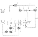
図1は、第1の実施形態による二重反転型プロペラを駆動する船舶用ハイブリッド推進装置の構成例を示す図、図2は、本実施形態による船舶用ハイブリッド推進装置の関数回路の特性図、図3は本実施形態による船舶用ハイブリッド推進装置の運転動作を示す特性図である。
(First embodiment)
FIG. 1 is a diagram illustrating a configuration example of a marine hybrid propulsion device that drives a contra-rotating propeller according to a first embodiment, and FIG. 2 is a characteristic diagram of a function circuit of the marine hybrid propulsion device according to the present embodiment. FIG. 3 is a characteristic diagram showing the operation of the marine hybrid propulsion device according to the present embodiment.
まず、図1を参照して第1の実施形態の船舶用ハイブリッド推進装置の構成について説明する。
第1の実施形態が、図8の従来例と異なる部分は、従来2個使用していた推進指令手段である推進レバーを1個に集約して、主機1が発生する馬力に基づいて電動機14の入力電力基準P*を求め、この電動機入力電力基準P*と実際に電動機14に入力される電力Pとから電動機14の速度を制御して固定ピッチプロペラ15を駆動するようにし、唯一の推進レバーによる簡単な操作で主機1によって駆動される可変ピッチプロペラ2の推進力と、電動機によって駆動される固定ピッチプロペラ15の推進力とに最適な分担比率をもたせるようにしたことにある。
First, the configuration of the marine hybrid propulsion device according to the first embodiment will be described with reference to FIG.
The first embodiment differs from the conventional example of FIG. 8 in that the propulsion levers, which are two conventional propulsion command means, are consolidated into one, and the
このため、本実施形態では、従来電気推進装置側に設けられていた推進レバー16および回転速度設定器17を撤去し、その代わりに以下述べる要素を新たに備えるようにした。
まず、主機1が発生する馬力を検出するために、主機1と可変ピッチプロペラ2の間の主機軸8に馬力計21を設け、さらに、この馬力計21から入力した馬力信号の大きさに応じて予め電動機入力電力基準P*を設定した関数回路22を設けるようにした。
For this reason, in the present embodiment, the
First, in order to detect the horsepower generated by the
この関数回路22は、二重反転型プロペラを効率的に運転するために、主機1の馬力から電動機14に入力すべき電力値を決定する関数を図2のような一次関数として予め設定しており、入力した主機1の馬力信号に比例した電動機入力電力基準P*を出力する。
This
なお、図2は主機1の馬力信号と電動機14の入力電力とが比例関係にある場合を例に示したが、二重反転型プロペラを効率的に運転するための主機馬力と電動機入力電力との比率は二重反転型プロペラの総合出力によって異なることも考えられるので、最も効率的な比率を関数回路22に設定すればよい。
FIG. 2 shows an example in which the horsepower signal of the
また、実際に電動機14に入力される電力Pを検出するために、電動機14の入力電圧および入力電流をそれぞれ検出する変圧器23および変流器24を設け、これら変圧器23および変流器24の出力電気量に基づいて電動機の入力電力Pを演算する電力検出器25を設けるようにした。
Further, in order to detect the electric power P actually inputted to the
さらに、前記関数回路22から出力された電動機入力電力基準P*および前記電力検出器25から出力された電動機の入力電力Pを入力し、電動機入力電力基準P*から電動機の入力電力Pを減算して偏差を求める減算器26と、この減算器26から出力される偏差(P*−P)を零にするために、例えばPI演算を行ってその演算結果を電動機14の回転速度基準N*として出力する電力制御器27とを設け、さらに、この回転速度基準N*が電動機14の定格回転速度以内になるように制限するリミッタ28を設けるようにした。なお、電力制御器27から出力される回転速度基準N*を前述した回転速度設定器17から出力される第2の回転速度基準と区別するために、便宜上第3の回転速度基準N*と呼ぶ。
Further, the motor input power reference P * output from the
このリミッタ28から出力された第3の回転速度基準N*は、従来例と同様に、回転速度制御器18に入力される。回転速度制御器18は、リミッタ28で制限された第3の回転速度基準N*と実測した回転速度Nとの差をインバータ13に入力する。
The third rotational speed reference N * output from the
以下、第1の実施形態の動作を説明する。
本実施形態による船舶用ハイブリッド推進装置を運転する際のタイムチャートの例を図3に示す。
時刻t1において、操船者が推進レバー5を前進側に操作した場合、推進レバー5の位置信号は「正」となって、主機1の馬力は図3の特性Aのように増加する。これにより、主機1の馬力に比例して主機1により駆動される可変ピッチプロペラ2が推進力を発生する。
The operation of the first embodiment will be described below.
An example of a time chart when operating the marine hybrid propulsion device according to this embodiment is shown in FIG.
When the boat operator operates the propulsion lever 5 forward at time t1, the position signal of the propulsion lever 5 becomes “positive”, and the horsepower of the
一方、主機1の馬力が増加すると、その馬力信号を入力している関数回路22から出力される電動機入力電力基準P*も増加する(図3の特性B参照)。
電動機入力電力基準P*が増加すると、第3の回転速度基準N*が増加するので、インバータ13はこの制限された第3の回転速度基準N*と実測した回転速度Nとの差に基づいて電動機14を駆動する。この結果、固定ピッチプロペラ15を駆動する電動機14の回転速度Nも上昇する(図3の特性C参照)。
On the other hand, when the horsepower of the
When the motor input power reference P * increases, the third rotational speed reference N * increases, so that the
電動機14の回転速度Nが上昇すると、電動機入力電力Pも増加し、電動機の出力基準P*に近づくこととなる。この結果、可変ピッチプロペラ2と固定ピッチプロペラ15の推進力が図3の特性Dで示すように船体を加速させる。ある程度船速が上昇した段階で、更に加速する場合は、操船者は例えば時刻t3で推進レバー5を更に前進側に操作して、位置信号を徐々に増加させ、船舶を加速させる。
When the rotational speed N of the
このように操船者が推進レバー5を操作した結果、主機1の馬力が変化し、二重反転型プロペラを効率的に運転できるように関数回路22で予め定めた関数に従って、電動機14の入力電力が制御される。
As a result of the operator operating the propulsion lever 5 in this way, the horsepower of the
以上述べたように、本発明の第1の実施形態によれば、主機1の馬力の大きさに応じて予め設定した関数回路22によって電動機14の入力電力基準P*を出力し、電動機14の入力電力基準値P*と実際の入力電力Pとを一致させるように制御を行って電動機14の回転速度基準N*を決定するようにしたので、操船者は船舶の推進力を調節するためには唯一の推進レバー5を操作すればよく、主機1による推進力と電動機14による推進力との比率は、二重反転型プロペラにとって効率的な運転を行うことができる比率となる。
As described above, according to the first embodiment of the present invention, the input power reference P * of the
(第2の実施形態)
以下、図4を参照して本発明の第2の実施形態について説明する。
図4は、第2の実施形態による船舶用ハイブリッド推進装置の構成例を示す図である。
以下、図4を参照して第2の実施形態による二重反転型プロペラを駆動する船舶用ハイブリッド推進装置について説明する。
(Second Embodiment)
Hereinafter, a second embodiment of the present invention will be described with reference to FIG.
FIG. 4 is a diagram illustrating a configuration example of the marine hybrid propulsion device according to the second embodiment.
Hereinafter, a marine hybrid propulsion device for driving a counter-rotating propeller according to a second embodiment will be described with reference to FIG.
第2の実施形態が第1の実施形態と構成上異なる部分は、図8で採用した回転速度設定器17を設けるとともに、この回転速度設定器17から出力された第2の回転速度基準あるいは前記電力制御器27から出力された第3の回転速度基準のいずれか一方を選択し当該選択された方の回転速度基準を前記回転速度制御器18に伝達する切替スイッチ29と、推進レバー5の位置信号に応じてこの切替スイッチ29に切替指令を与える切替回路30とを設けたことにある。なお、切替スイッチ29および切替回路30を合せて切替手段と呼ぶ。
The second embodiment is different from the first embodiment in configuration in that the
以下、第2の実施形態の動作を説明する。
回転速度設定器17は推進レバー5の位置信号を入力し、電動機14の回転速度基準N*(第2の回転速度基準)を出力する。切替回路30は、推進レバー5の位置信号が前進側の「正」または中立状態の「0」の場合には、切替スイッチ29に対してリミッタ28と回転速度制御器18とを接続するように指令を出してリミッタ28と回転速度制御器18とを接続させ、リミッタ28から出力される第3の回転速度基準N*を回転速度制御器18へ伝達させる。
The operation of the second embodiment will be described below.
The
一方、推進レバー5の位置信号が後進側の「負」である場合には、切替回路30は切替スイッチ29に対して回転速度設定器17と回転速度制御器18とを接続するように指令を出して回転速度設定器17と回転速度制御器18とを接続させ、回転速度設定器17から出力される第2の回転速度基準N*を回転速度制御器18へ伝達させる。
On the other hand, when the position signal of the propulsion lever 5 is “negative” on the reverse side, the switching
切替スイッチ29がリミッタ28と回転速度制御器18とを接続している場合は、回転速度制御器7、主機燃料制御装置10、主機1、馬力計21、電力制御器27等からなる制御系に遅れ要素があるため、操船者の推進レバー5の操作に対して電動機14ヘの回転速度基準N*の応答は遅くなっている。
したがって、この状態で船舶が障害物を回避する際に後進操作を行った場合には、船舶速度の応答性が悪化する問題がある。
When the
Therefore, when the ship performs a reverse operation when avoiding an obstacle in this state, there is a problem that the responsiveness of the ship speed deteriorates.
しかしながら、第2の実施形態では、推進レバー5の位置信号が後進側の「負」である場合、切替回路30および切替スイッチ29からなる切替手段の働きにより回転速度設定器17と回転速度制御器18とを接続させて前述した遅れ要素をバイパスして第2の回転速度基準N*を回転速度制御器18へ伝達させるようにしたので、推進レバー5の操作に対する電動機14が発生する推進力の応答性が向上し、船舶の速度の応答性を向上させることができる。
However, in the second embodiment, when the position signal of the propulsion lever 5 is “negative” on the reverse side, the rotational
以上述べたように、第2の実施形態によれば、船舶の前進航行時は第1の実施形態と同様に、主機による推進力と電動機による推進力の比率は効率的な運転を行うことができる比率となるとともに、非常時の後進操作時においては迅速に後進に移行することができる。また、主機1を停止した状態で、電動機14による推進力のみで低速航行する場合、切替回路30を動作させずに切替スイッチ29を回転速度設定器17と回転速度制御器18とを接続する構成とすることにより、操船者が推進レバー5のみで電動機14の回転速度を調節することができる。
As described above, according to the second embodiment, the ratio of the propulsive force by the main engine and the propulsive force by the electric motor can be efficiently operated during the forward navigation of the ship as in the first embodiment. It is possible to shift to the reverse speed quickly at the time of reverse operation in an emergency. Further, in the case where the
(第3の実施形態)
以下、図5を参照して本発明の第3の実施形態について説明する。
図5は、第3の実施形態による船舶用ハイブリッド推進装置の構成例を示す図である。
以下、図5を参照して第3の実施形態による二重反転型プロペラを駆動する船舶用ハイブリッド推進装置について説明する。
(Third embodiment)
Hereinafter, a third embodiment of the present invention will be described with reference to FIG.
FIG. 5 is a diagram illustrating a configuration example of the marine hybrid propulsion device according to the third embodiment.
Hereinafter, a marine hybrid propulsion device for driving a counter-rotating propeller according to a third embodiment will be described with reference to FIG.
第3の実施形態が第1の実施形態と構成上異なる部分は、第1の実施形態では電動機14の回転速度を調節することによって固定ピッチプロペラ15の推進力を調節する構成であることに対し、本実施形態では電動機14の回転速度を制御せずにほぼ一定値にし、固定ピッチプロペラ15に替えて設けた第2の可変ピッチプロペラ31の翼角を調節することによって推進力を調節するように構成したことにある。
The third embodiment differs in configuration from the first embodiment in that the propulsive force of the fixed
このため、第3の実施形態では、電動機14で駆動される固定ピッチプロペラ15を第2の可変ピッチプロペラ31に置き換えるほか、インバータ13、回転速度検出器20、電力制御器27、リミッタ28、回転速度制御器18を撤去し、代わりに電動機14の電動機軸19に第2の変節装置32を設け、さらに減算器26の後段に電力制御器27、リミッタ28に替わる別の電力制御器33およびリミッタ34を設け、発電機11で直接電動機14に電力を供給するようにした。
For this reason, in the third embodiment, the fixed
以下、第3の実施形態の動作を説明する。
発電機11は補機原動機12によってほぼ一定回転速度で駆動されているため、出力周波数はほぼ一定である。電動機14はインバータを介さずに発電機11から直接電圧を印加されるので、その回転速度はほぼ一定である。このときの電動機14の入力電力Pは、電力検出器25が変圧器23および変流器24から入力した電圧および電流に基づいて演算する。
第2の可変ピッチプロペラ31は電動機軸19を介して電動機14によって回転駆動される。
The operation of the third embodiment will be described below.
Since the
The second
本実施形態で設けた電力制御器33は、例えばPI制御器で構成され、関数回路22の電力基準P*から電力検出器25の電動機入力電力Pを減算して得た偏差(P*−P)を零にするための制御演算を行い、その演算結果を翼角信号としてリミッタ34へ出力する。なお、電力制御器33から出力された翼角信号を後述する翼角設定器35から出力される翼角信号と区別するために、第1の翼角信号と呼ぶ。
The
リミッタ34は電力制御器33から出力された翼角信号を第2の変節装置32の制御可能な範囲に制限して変節装置32に出力する。第2の変節装置32はこの翼角信号を受けて第2の可変ピッチプロペラ31の翼角を調整する。
The
以上述べたように、第3の実施形態によれば、主機1の馬力から電動機14の入力電力基準を決定し、電動機14の入力電力基準値P*と実際の入力電力Pが一致するように電力制御を行って第2の可変ピッチプロペラ31の翼角を決定するようにしたので、操船者は推進力を調節するためには推進レバー5のみを操作すればよく、主機1による推進力と電動機14による推進力の比率は効率的な運転を行うことができる比率となる。
As described above, according to the third embodiment, the input power reference of the
(第4の実施形態)
以下、図6および図7を参照して本発明の第4の実施形態について説明する。
図6は、本実施形態による船舶用ハイブリッド推進装置の構成例を示す図である。
以下、図6を参照して第4の実施形態による二重反転型プロペラを駆動する船舶用ハイブリッド推進装置について説明する。
(Fourth embodiment)
The fourth embodiment of the present invention will be described below with reference to FIGS.
FIG. 6 is a diagram illustrating a configuration example of the marine hybrid propulsion device according to the present embodiment.
A marine hybrid propulsion device for driving a counter-rotating propeller according to a fourth embodiment will be described below with reference to FIG.
第4の実施形態が第3の実施形態と構成上異なる部分は、推進レバー5の位置信号に応じて翼角基準を出力する翼角設定器35と、第2の実施形態(図4)で採用した切替スイッチ29および切替回路30から成る切替手段とを設けるようにしたことにある。なお、翼角設定器35から出力された翼角基準を第1の翼角基準と区別するために第2の翼角基準と呼ぶ。
The fourth embodiment differs in configuration from the third embodiment in the blade
以下、第4の実施形態の動作を説明する。
操船者が推進レバー5を操作すると、翼角設定器35は推進レバー5の位置信号を入力し、第2の可変ピッチプロペラ31の翼角基準を出力する。
The operation of the fourth embodiment will be described below.
When the operator operates the propulsion lever 5, the blade
翼角設定器35の特性は図7で示すように、入力した推進レバー5の位置信号と翼角基準の関係は、前進側の最大値D1から中立状態の0点を通って後進側の最大値−D1迄の間直線的にW1から−W1まで変化するように定められている。
Characteristics of the blade
切替回路30は、第2の実施形態と同様に、推進レバー5の位置信号が前進側の「正」または中立状態の「0」の場合には、切替スイッチ29をリミッタ34に接続させることによって、リミッタ34と第2の変節装置32とを接続させ、リミッタ34から出力される第1の翼角基準を第2の変節装置32へ伝達させる。
As in the second embodiment, the switching
一方、推進レバー5の位置信号が後進側の「負」である場合には、切替回路30は切替スイッチ29を翼角設定器35に接続させることによって、翼角設定器35と第2の変節装置32を接続させ、翼角設定器35から出力される第2の翼角基準を変節装置32へ伝達させる。
On the other hand, when the position signal of the propulsion lever 5 is “negative” on the reverse side, the
切替スイッチ29がリミッタ34と変節装置32を接続している場合は、操船者による推進レバー5の操作に対して回転速度制御器7、主機燃料制御装置10、主機1、馬力計21、電力制御器33等の遅れ要素があるため、操船者の推進レバー5の操作に対して、第2の可変ピッチプロペラ31の翼角の応答が遅くなっている。
したがって、この状態で船舶が障害物を回避する場合などの後進操作を行った場合には、船舶の速度の応答性が悪化する問題がある。
When the
Therefore, when a reverse operation is performed such as when the ship avoids an obstacle in this state, there is a problem that the responsiveness of the speed of the ship deteriorates.
しかしながら、第4の実施形態では、推進レバー5の位置信号が後進側の「負」である場合、切替回路30および切替スイッチ29からなる切替手段の働きにより翼角設定器35と第2の変節装置32とを接続させて前述した遅れ要素をバイパスして、第2の翼角基準を第2の変節装置32へ伝達させるようにしたので、推進レバー5の操作に対する電動機14が発生する推進力の応答性が向上し、船舶の速度の応答性を向上させることができる。
However, in the fourth embodiment, when the position signal of the propulsion lever 5 is “negative” on the reverse side, the wing
以上述べたように、第4の実施形態によれば、船舶の前進航行時は第3の実施形態と同様に、主機1による推進力と電動機14による推進力の比率は効率的な運転を行うことができる比率となるとともに、非常時の後進操作時においては迅速に後進に移行することができる。
As described above, according to the fourth embodiment, the ratio of the propulsive force generated by the
また、主機1を停止した状態で、電動機14による推進力のみで低速航行する場合、切替回路30を動作させずに切替スイッチ29を翼角設定器35と第2の変節装置32を接続する構成とすることにより、操船者が推進レバー5のみで第2の可変ピッチプロペラ31の翼角を調節することができる。
Further, when the
1…主機、2…可変ピッチプロペラ、3…第1の変節装置、4…翼角設定器、5…推進指令手段(推進レバー)、6…回転速度設定器、7…回転速度制御器、8…主機軸、9…回転速度検出器、10…主機燃料制御装置、11…発電機、12…補機原動機、13…インバータ、14…電動機、15…固定ピッチプロペラ、17…回転速度設定器、18…回転速度制御器、19…電動機軸、20…回転速度検出器、21…馬力計、22…関数回路、23…変圧器、24…変流器、25…電力検出器、26…減算器、27…電力制御器、28…リミッタ、29…切替スイッチ、30…切替回路、31…第2の可変ピッチプロペラ、32…第2の変節装置、33…電力制御器、34…リミッ夕、35…翼角設定器。
DESCRIPTION OF
Claims (4)
前記主機により回転駆動される可変ピッチプロペラと、
前記可変ピッチプロペラの翼角を制御する第1の変節装置と、
前記推進指令手段から出力される位置信号に基づいて前記第1の変節装置に翼角信号を与える翼角設定器と、
前記可変ピッチプロペラと同一直線上に接近させて配置され、当該可変ピッチプロペラとともに二重反転型プロペラを構成する固定ピッチプロペラと、
前記固定ピッチプロペラを駆動する電動機と、
前記電動機の回転速度を検出する回転速度検出器と、
前記電動機を可変速駆動するインバータと、
前記インバータに電力を供給する電源と、
前記主機が出力する馬力を検出する馬力検出器と、
前記馬力検出器から出力された馬力検出信号の増減に追従して増減するように設定された関数によって電動機入力電力基準を出力する関数回路と、
前記電動機の入力電力を検出する電力検出器と、
前記関数回路より出力された電動機入力電力基準と前記電動機の入力電力との偏差を零にするように制御演算を行いその結果を第2の回転速度基準として出力する電力制御器と、
前記電力制御器から出力された第2の回転速度基準と前記回転速度検出器から出力された回転速度信号とが一致するように両信号の偏差を制御信号として前記インバータに与える回転速度制御器と、
を備えたことを特徴とする船舶用ハイブリッド推進装置。 A main engine whose rotation speed is controlled in accordance with a first rotation speed reference based on a position signal output from the propulsion command means;
A variable pitch propeller driven to rotate by the main machine;
A first shift device for controlling a blade angle of the variable pitch propeller;
A wing angle setter for providing a wing angle signal to the first shift device based on a position signal output from the propulsion command means;
A fixed pitch propeller arranged close to the same pitch as the variable pitch propeller and constituting a counter-rotating propeller together with the variable pitch propeller;
An electric motor for driving the fixed pitch propeller;
A rotational speed detector for detecting the rotational speed of the electric motor;
An inverter for driving the electric motor at a variable speed;
A power supply for supplying power to the inverter;
A horsepower detector that detects the horsepower output by the main engine;
A function circuit that outputs a motor input power reference by a function set to increase or decrease following the increase or decrease of the horsepower detection signal output from the horsepower detector;
A power detector for detecting input power of the motor;
A power controller that performs a control operation so that a deviation between the motor input power reference output from the function circuit and the input power of the motor is zero, and outputs the result as a second rotation speed reference;
A rotation speed controller that gives a deviation of both signals to the inverter as a control signal so that the second rotation speed reference output from the power controller and the rotation speed signal output from the rotation speed detector coincide with each other; ,
A marine hybrid propulsion device comprising:
前記推進指令手段から出力される位置信号に基づいて前記電動機の第3の回転速度基準を出力する回転速度設定器と、
前記推進指令手段から出力される位置信号に基づいて前記電力制御器あるいは前記回転速度設定器のいずれか一方を選択し当該選択された方の回転速度基準を前記インバータに伝達する切替手段とを備え、
前記推進指令手段から出力される位置信号が船舶を前進させる信号である場合は、前記電力制御器を前記インバータの回転速度制御器に接続して前記第2の回転速度基準を前記インバータに伝達し、前記推進指令手段から出力される位置信号が船舶を後進させる位置信号である場合は、前記回転速度設定器を前記インバータの回転速度制御器に接続して前記第3の回転速度基準を前記インバータに伝達することを特徴とする船舶用ハイブリッド推進装置。 In the marine hybrid propulsion device according to claim 1,
A rotational speed setter for outputting a third rotational speed reference of the electric motor based on a position signal output from the propulsion command means;
Switching means for selecting either the power controller or the rotation speed setting device based on the position signal output from the propulsion command means and transmitting the selected rotation speed reference to the inverter. ,
When the position signal output from the propulsion command means is a signal for advancing the ship, the power controller is connected to the rotation speed controller of the inverter to transmit the second rotation speed reference to the inverter. When the position signal output from the propulsion command means is a position signal for moving the ship backward, the rotation speed setting device is connected to the rotation speed controller of the inverter, and the third rotation speed reference is set to the inverter. A marine hybrid propulsion device, characterized in that
前記主機により回転駆動される第1の可変ピッチプロペラと、
前記第1の可変ピッチプロペラ2の翼角を制御する第1の変節装置と、
前記推進指令手段から出力される位置信号に基づいて前記第1の変節装置に翼角信号を与える翼角設定器と、
前記第1の可変ピッチプロペラと同一直線上に接近させて配置され、当該第1の可変ピッチプロペラとともに二重反転型プロペラを構成する第2の可変ピッチプロペラと、
前記第2の可変ピッチプロペラを駆動する電動機と、
前記第2の可変ピッチプロペラの翼角を制御する第2の変節装置と、
前記電動機に電力を供給する交流電源と、
前記主機が出力する馬力を検出する馬力検出器と、
前記馬力検出器から出力される馬力検出信号の増減に追従して増減するように設定された関数によって電動機入力電力基準を出力する関数回路と、
前記電動機の入力電力を検出する電力検出器と、
前記関数回路より出力された電動機入力電力基準と前記電力検出器から出力された電動機の入力電力との偏差を零にするように制御演算を行いその結果を前記第2の変節装置に第1の翼角基準として出力する電力制御器と、
を備えたことを特徴とする船舶用ハイブリッド推進装置。 A main engine whose rotation speed is controlled in accordance with a first rotation speed reference based on a position signal output from the propulsion command means;
A first variable pitch propeller that is rotationally driven by the main machine;
A first inflection device for controlling a blade angle of the first variable pitch propeller 2;
A wing angle setter for providing a wing angle signal to the first shift device based on a position signal output from the propulsion command means;
A second variable pitch propeller disposed close to the same straight line as the first variable pitch propeller and constituting a counter-rotating propeller together with the first variable pitch propeller;
An electric motor for driving the second variable pitch propeller;
A second shift device for controlling a blade angle of the second variable pitch propeller;
An AC power supply for supplying power to the motor;
A horsepower detector that detects the horsepower output by the main engine;
A function circuit that outputs a motor input power reference by a function set to increase or decrease following the increase or decrease of the horsepower detection signal output from the horsepower detector;
A power detector for detecting input power of the motor;
A control calculation is performed so that the deviation between the motor input power reference output from the function circuit and the motor input power output from the power detector is zero, and the result is sent to the second shift device as a first. A power controller that outputs as a blade angle reference;
A marine hybrid propulsion device comprising:
前記推進指令手段から出力される位置信号に基づいて前記第2の可変ピッチプロペラの第2の翼角基準を出力する翼角設定器と、
前記推進指令手段から出力される位置信号に基づいて前記電力制御器あるいは前記翼角設定器のいずれか一方を選択し当該選択された方の翼角基準を前記第2の変節装置に伝達する切替手段とを備え、
前記推進指令手段から出力される位置信号が船舶を前進させる信号である場合は、前記電力制御器を前記第2の変節装置に接続して前記第1の翼角基準を前記第2の変節装置に伝達し、前記推進指令手段から出力される位置信号が船舶を後進させる場合は、前記翼角設定器を前記第2の変節装置に接続して前記第2の翼角基準を前記第2の変節装置に伝達することを特徴とする船舶用ハイブリッド推進装置。 The marine hybrid propulsion device according to claim 3,
A blade angle setter for outputting a second blade angle reference of the second variable pitch propeller based on a position signal output from the propulsion command means;
Switching that selects either the power controller or the blade angle setting device based on the position signal output from the propulsion command means and transmits the selected blade angle reference to the second shift device. Means and
When the position signal output from the propulsion command means is a signal for advancing the ship, the power controller is connected to the second shift device to set the first blade angle reference to the second shift device. When the position signal output from the propulsion command means causes the ship to move backward, the wing angle setting device is connected to the second shift device to set the second wing angle reference to the second wing angle reference. A marine hybrid propulsion device that transmits to a shift device.
Priority Applications (1)
| Application Number | Priority Date | Filing Date | Title |
|---|---|---|---|
| JP2008302696A JP5164043B2 (en) | 2008-11-27 | 2008-11-27 | Marine hybrid propulsion system |
Applications Claiming Priority (1)
| Application Number | Priority Date | Filing Date | Title |
|---|---|---|---|
| JP2008302696A JP5164043B2 (en) | 2008-11-27 | 2008-11-27 | Marine hybrid propulsion system |
Publications (2)
| Publication Number | Publication Date |
|---|---|
| JP2010125987A true JP2010125987A (en) | 2010-06-10 |
| JP5164043B2 JP5164043B2 (en) | 2013-03-13 |
Family
ID=42326665
Family Applications (1)
| Application Number | Title | Priority Date | Filing Date |
|---|---|---|---|
| JP2008302696A Active JP5164043B2 (en) | 2008-11-27 | 2008-11-27 | Marine hybrid propulsion system |
Country Status (1)
| Country | Link |
|---|---|
| JP (1) | JP5164043B2 (en) |
Cited By (8)
| Publication number | Priority date | Publication date | Assignee | Title |
|---|---|---|---|---|
| CN102120488A (en) * | 2011-03-07 | 2011-07-13 | 上海海事大学 | Electric propulsion system for hybrid power boats and implementation method thereof |
| CN102211657A (en) * | 2011-05-11 | 2011-10-12 | 上海海事大学 | Ship electric propulsion system with hybrid power supply of diesel generator set and power battery |
| WO2014141902A1 (en) * | 2013-03-14 | 2014-09-18 | ヤンマー株式会社 | Ship |
| WO2016052213A1 (en) * | 2014-09-30 | 2016-04-07 | 三菱重工業株式会社 | Ship propulsion system and ship having same |
| DE102015220418A1 (en) | 2014-10-28 | 2016-05-25 | Toyota Jidosha Kabushiki Kaisha | DEVICE FOR SUPPRESSING ONE VIBRATION OF A SPRINGED MASS FOR A VEHICLE |
| JP2016135632A (en) * | 2015-01-23 | 2016-07-28 | 三菱重工業株式会社 | Integration control apparatus for ship, ship equipped with same, and integration control method and program |
| JP2023071372A (en) * | 2021-11-11 | 2023-05-23 | 川崎重工業株式会社 | Ship propulsion system, ship propulsion control method, and ship propulsion control program |
| EP4365076A1 (en) | 2022-10-19 | 2024-05-08 | Yamaha Hatsudoki Kabushiki Kaisha | Watercraft propulsion system, watercraft and watercraft propulsion control method |
Citations (5)
| Publication number | Priority date | Publication date | Assignee | Title |
|---|---|---|---|---|
| JPH0656082A (en) * | 1992-08-07 | 1994-03-01 | Kawasaki Heavy Ind Ltd | Marine counter-rotating propeller |
| JPH06165585A (en) * | 1992-11-25 | 1994-06-10 | Toshiba Corp | Power converter |
| JPH10138997A (en) * | 1996-11-08 | 1998-05-26 | Nishishiba Electric Co Ltd | Electric propulsion propeller drive |
| JP2006522711A (en) * | 2003-04-11 | 2006-10-05 | エービービー・オーワイ | Method and apparatus for controlling a ship |
| JP2007174799A (en) * | 2005-12-21 | 2007-07-05 | Toshiba Mitsubishi-Electric Industrial System Corp | Marine electric propulsion system |
-
2008
- 2008-11-27 JP JP2008302696A patent/JP5164043B2/en active Active
Patent Citations (5)
| Publication number | Priority date | Publication date | Assignee | Title |
|---|---|---|---|---|
| JPH0656082A (en) * | 1992-08-07 | 1994-03-01 | Kawasaki Heavy Ind Ltd | Marine counter-rotating propeller |
| JPH06165585A (en) * | 1992-11-25 | 1994-06-10 | Toshiba Corp | Power converter |
| JPH10138997A (en) * | 1996-11-08 | 1998-05-26 | Nishishiba Electric Co Ltd | Electric propulsion propeller drive |
| JP2006522711A (en) * | 2003-04-11 | 2006-10-05 | エービービー・オーワイ | Method and apparatus for controlling a ship |
| JP2007174799A (en) * | 2005-12-21 | 2007-07-05 | Toshiba Mitsubishi-Electric Industrial System Corp | Marine electric propulsion system |
Cited By (14)
| Publication number | Priority date | Publication date | Assignee | Title |
|---|---|---|---|---|
| CN102120488A (en) * | 2011-03-07 | 2011-07-13 | 上海海事大学 | Electric propulsion system for hybrid power boats and implementation method thereof |
| CN102211657A (en) * | 2011-05-11 | 2011-10-12 | 上海海事大学 | Ship electric propulsion system with hybrid power supply of diesel generator set and power battery |
| WO2014141902A1 (en) * | 2013-03-14 | 2014-09-18 | ヤンマー株式会社 | Ship |
| JP2014177189A (en) * | 2013-03-14 | 2014-09-25 | Yanmar Co Ltd | Marine vessel |
| CN105189283A (en) * | 2013-03-14 | 2015-12-23 | 洋马株式会社 | Ship |
| JP2016068847A (en) * | 2014-09-30 | 2016-05-09 | 三菱重工業株式会社 | Ship propulsion system and ship having the same |
| WO2016052213A1 (en) * | 2014-09-30 | 2016-04-07 | 三菱重工業株式会社 | Ship propulsion system and ship having same |
| CN106660623A (en) * | 2014-09-30 | 2017-05-10 | 三菱重工业株式会社 | Ship propulsion system and ship having same |
| DE102015220418A1 (en) | 2014-10-28 | 2016-05-25 | Toyota Jidosha Kabushiki Kaisha | DEVICE FOR SUPPRESSING ONE VIBRATION OF A SPRINGED MASS FOR A VEHICLE |
| DE102015220418B4 (en) | 2014-10-28 | 2022-05-05 | Toyota Jidosha Kabushiki Kaisha | SUSPENDED MASS VIBRATION SUPPRESSION DEVICE FOR A VEHICLE |
| JP2016135632A (en) * | 2015-01-23 | 2016-07-28 | 三菱重工業株式会社 | Integration control apparatus for ship, ship equipped with same, and integration control method and program |
| JP2023071372A (en) * | 2021-11-11 | 2023-05-23 | 川崎重工業株式会社 | Ship propulsion system, ship propulsion control method, and ship propulsion control program |
| JP7296438B2 (en) | 2021-11-11 | 2023-06-22 | 川崎重工業株式会社 | Ship propulsion system, ship propulsion control method, and ship propulsion control program |
| EP4365076A1 (en) | 2022-10-19 | 2024-05-08 | Yamaha Hatsudoki Kabushiki Kaisha | Watercraft propulsion system, watercraft and watercraft propulsion control method |
Also Published As
| Publication number | Publication date |
|---|---|
| JP5164043B2 (en) | 2013-03-13 |
Similar Documents
| Publication | Publication Date | Title |
|---|---|---|
| JP5164043B2 (en) | Marine hybrid propulsion system | |
| JP6284558B2 (en) | Electric propulsion device for ship, propulsion force control device used for electric propulsion device for ship | |
| JP5126751B2 (en) | Marine electric propulsion system | |
| WO2015182157A1 (en) | Hybrid propulsion system for mobile object, and method for controlling said system | |
| JP3911517B2 (en) | Hybrid system | |
| JP5419028B1 (en) | Main shaft drive generator motor propulsion device | |
| JP2012087750A (en) | Hybrid propulsion system control and surveillance apparatus for vessel | |
| JP2015112883A (en) | Electric propulsion ship control device, electric propulsion ship control system, and electric propulsion ship | |
| JP2913464B2 (en) | Electric propulsion propeller drive | |
| JP5951587B2 (en) | Control apparatus, ship equipped with the same, and integrated control method | |
| WO2016052213A1 (en) | Ship propulsion system and ship having same | |
| JP7142519B2 (en) | marine power transmission | |
| US10730599B2 (en) | Marine vessel power system and method | |
| JP2012166603A (en) | Control method for twin-screw vessel and twin-screw vessel | |
| AU2014270720B2 (en) | Optimization of a drive system comprising a variable pitch propeller in a water vehicle during a stopping maneuver | |
| JP5540134B1 (en) | Electric propulsion device for ships | |
| JP7060491B2 (en) | Hybrid system for ships | |
| JP2010000973A (en) | Electric motor driving system for vessel | |
| JP2016159803A (en) | Ship | |
| US12132438B2 (en) | Induction motor control via generator control unit | |
| JPH10218094A (en) | Compound propeller device for ship | |
| JP5561468B2 (en) | Inverter system for marine electric propulsion system | |
| JPH09224389A (en) | Control device for electric motor | |
| JP2011160620A5 (en) |
Legal Events
| Date | Code | Title | Description |
|---|---|---|---|
| A621 | Written request for application examination |
Free format text: JAPANESE INTERMEDIATE CODE: A621 Effective date: 20111108 |
|
| A977 | Report on retrieval |
Free format text: JAPANESE INTERMEDIATE CODE: A971007 Effective date: 20121102 |
|
| TRDD | Decision of grant or rejection written | ||
| A01 | Written decision to grant a patent or to grant a registration (utility model) |
Free format text: JAPANESE INTERMEDIATE CODE: A01 Effective date: 20121113 |
|
| A61 | First payment of annual fees (during grant procedure) |
Free format text: JAPANESE INTERMEDIATE CODE: A61 Effective date: 20121210 |
|
| FPAY | Renewal fee payment (event date is renewal date of database) |
Free format text: PAYMENT UNTIL: 20151228 Year of fee payment: 3 |
|
| R150 | Certificate of patent or registration of utility model |
Ref document number: 5164043 Country of ref document: JP Free format text: JAPANESE INTERMEDIATE CODE: R150 Free format text: JAPANESE INTERMEDIATE CODE: R150 |