JP2010080872A - Solar battery device - Google Patents
Solar battery device Download PDFInfo
- Publication number
- JP2010080872A JP2010080872A JP2008250507A JP2008250507A JP2010080872A JP 2010080872 A JP2010080872 A JP 2010080872A JP 2008250507 A JP2008250507 A JP 2008250507A JP 2008250507 A JP2008250507 A JP 2008250507A JP 2010080872 A JP2010080872 A JP 2010080872A
- Authority
- JP
- Japan
- Prior art keywords
- solar cell
- cell module
- pedestal
- main
- sub
- Prior art date
- Legal status (The legal status is an assumption and is not a legal conclusion. Google has not performed a legal analysis and makes no representation as to the accuracy of the status listed.)
- Granted
Links
Images


Classifications
-
- F—MECHANICAL ENGINEERING; LIGHTING; HEATING; WEAPONS; BLASTING
- F24—HEATING; RANGES; VENTILATING
- F24S—SOLAR HEAT COLLECTORS; SOLAR HEAT SYSTEMS
- F24S40/00—Safety or protection arrangements of solar heat collectors; Preventing malfunction of solar heat collectors
- F24S40/40—Preventing corrosion; Protecting against dirt or contamination
- F24S40/44—Draining rainwater or condensation
-
- F—MECHANICAL ENGINEERING; LIGHTING; HEATING; WEAPONS; BLASTING
- F24—HEATING; RANGES; VENTILATING
- F24S—SOLAR HEAT COLLECTORS; SOLAR HEAT SYSTEMS
- F24S25/00—Arrangement of stationary mountings or supports for solar heat collector modules
- F24S25/10—Arrangement of stationary mountings or supports for solar heat collector modules extending in directions away from a supporting surface
-
- F—MECHANICAL ENGINEERING; LIGHTING; HEATING; WEAPONS; BLASTING
- F24—HEATING; RANGES; VENTILATING
- F24S—SOLAR HEAT COLLECTORS; SOLAR HEAT SYSTEMS
- F24S25/00—Arrangement of stationary mountings or supports for solar heat collector modules
- F24S25/20—Peripheral frames for modules
-
- F—MECHANICAL ENGINEERING; LIGHTING; HEATING; WEAPONS; BLASTING
- F24—HEATING; RANGES; VENTILATING
- F24S—SOLAR HEAT COLLECTORS; SOLAR HEAT SYSTEMS
- F24S25/00—Arrangement of stationary mountings or supports for solar heat collector modules
- F24S25/30—Arrangement of stationary mountings or supports for solar heat collector modules using elongate rigid mounting elements extending substantially along the supporting surface, e.g. for covering buildings with solar heat collectors
- F24S25/33—Arrangement of stationary mountings or supports for solar heat collector modules using elongate rigid mounting elements extending substantially along the supporting surface, e.g. for covering buildings with solar heat collectors forming substantially planar assemblies, e.g. of coplanar or stacked profiles
- F24S25/35—Arrangement of stationary mountings or supports for solar heat collector modules using elongate rigid mounting elements extending substantially along the supporting surface, e.g. for covering buildings with solar heat collectors forming substantially planar assemblies, e.g. of coplanar or stacked profiles by means of profiles with a cross-section defining separate supporting portions for adjacent modules
-
- F—MECHANICAL ENGINEERING; LIGHTING; HEATING; WEAPONS; BLASTING
- F24—HEATING; RANGES; VENTILATING
- F24S—SOLAR HEAT COLLECTORS; SOLAR HEAT SYSTEMS
- F24S25/00—Arrangement of stationary mountings or supports for solar heat collector modules
- F24S25/60—Fixation means, e.g. fasteners, specially adapted for supporting solar heat collector modules
- F24S25/63—Fixation means, e.g. fasteners, specially adapted for supporting solar heat collector modules for fixing modules or their peripheral frames to supporting elements
- F24S25/634—Clamps; Clips
- F24S25/636—Clamps; Clips clamping by screw-threaded elements
-
- Y—GENERAL TAGGING OF NEW TECHNOLOGICAL DEVELOPMENTS; GENERAL TAGGING OF CROSS-SECTIONAL TECHNOLOGIES SPANNING OVER SEVERAL SECTIONS OF THE IPC; TECHNICAL SUBJECTS COVERED BY FORMER USPC CROSS-REFERENCE ART COLLECTIONS [XRACs] AND DIGESTS
- Y02—TECHNOLOGIES OR APPLICATIONS FOR MITIGATION OR ADAPTATION AGAINST CLIMATE CHANGE
- Y02B—CLIMATE CHANGE MITIGATION TECHNOLOGIES RELATED TO BUILDINGS, e.g. HOUSING, HOUSE APPLIANCES OR RELATED END-USER APPLICATIONS
- Y02B10/00—Integration of renewable energy sources in buildings
- Y02B10/10—Photovoltaic [PV]
-
- Y—GENERAL TAGGING OF NEW TECHNOLOGICAL DEVELOPMENTS; GENERAL TAGGING OF CROSS-SECTIONAL TECHNOLOGIES SPANNING OVER SEVERAL SECTIONS OF THE IPC; TECHNICAL SUBJECTS COVERED BY FORMER USPC CROSS-REFERENCE ART COLLECTIONS [XRACs] AND DIGESTS
- Y02—TECHNOLOGIES OR APPLICATIONS FOR MITIGATION OR ADAPTATION AGAINST CLIMATE CHANGE
- Y02E—REDUCTION OF GREENHOUSE GAS [GHG] EMISSIONS, RELATED TO ENERGY GENERATION, TRANSMISSION OR DISTRIBUTION
- Y02E10/00—Energy generation through renewable energy sources
- Y02E10/40—Solar thermal energy, e.g. solar towers
- Y02E10/47—Mountings or tracking
Landscapes
- Engineering & Computer Science (AREA)
- Physics & Mathematics (AREA)
- Life Sciences & Earth Sciences (AREA)
- Sustainable Development (AREA)
- Sustainable Energy (AREA)
- Thermal Sciences (AREA)
- Chemical & Material Sciences (AREA)
- Combustion & Propulsion (AREA)
- Mechanical Engineering (AREA)
- General Engineering & Computer Science (AREA)
- Roof Covering Using Slabs Or Stiff Sheets (AREA)
- Photovoltaic Devices (AREA)
Abstract
Description
本発明は、太陽電池モジュールが架台に取付られて構成される太陽電池装置に関する。 The present invention relates to a solar cell device configured by attaching a solar cell module to a mount.
太陽電池装置は、一般的に、太陽電池モジュールが架台に取付られて構成されている。この太陽電池装置における太陽電池モジュールは、一般的に、矩形状の太陽電池パネルと、この太陽電池パネルを保持する枠部材とで構成されている。 Generally, a solar cell device is configured by attaching a solar cell module to a gantry. The solar cell module in this solar cell device is generally composed of a rectangular solar cell panel and a frame member that holds the solar cell panel.
この太陽電池パネルを保持する枠部材としては、一般に、太陽電池パネルの周辺を挟持して保持する保持部と、この保持部の下に連設された台座部とで構成された構造の枠部材が用いられている(例えば、特許文献1の図2、図5参照)。 As a frame member for holding the solar cell panel, generally, a frame member having a structure constituted by a holding unit that holds and holds the periphery of the solar cell panel, and a pedestal unit provided below the holding unit. Is used (see, for example, FIGS. 2 and 5 of Patent Document 1).
この枠部材における保持部は、立設された保持壁と、該保持壁の上端及び下端から内側に向かって張設され、相互間に太陽電池パネルの辺の端縁部を嵌入して保持する保持上片、及び、保持下片とで構成され、断面がコの字形をしている。 The holding portion in this frame member is extended from the upper and lower ends of the holding wall to the inside, and the edge portion of the side of the solar cell panel is inserted and held between them. It consists of a holding upper piece and a holding lower piece, and has a U-shaped cross section.
この断面がコの字形をした保持部を備えた枠部材を用いる太陽電池モジュールでは、この断面がコの字形をした保持部の内部に、上述したように、太陽電池パネルの周辺を挿入して挟持することにより、太陽電池パネルを保持した太陽電池モジュールを形成している。 In the solar cell module using the frame member provided with the holding portion having the U-shaped cross section, as described above, the periphery of the solar cell panel is inserted into the holding portion having the U-shaped cross section. By sandwiching, a solar cell module holding the solar cell panel is formed.
このように構成された太陽電池モジュールは、この太陽電池モジュールの保持部の下に連設された台座部の底面が、架台の上面に接するようにして、架台上に載置されて固定されて、太陽電池装置が形成される(例えば、特許文献1の図7参照)。複数の太陽電池モジュールが使用される場合は、複数の上記の太陽電池モジュールが、上記の架台上に並べられて固定される。
ところで、上記の太陽電池装置において、上記の保持部と台座部とで構成される構造の枠部材を用いた太陽電池モジュールは、この太陽電池モジュールの重量増加を抑制しつつ、強度の増加を図るために、枠部材の台座部の部分が、次のように構成されている。 By the way, in the solar cell device described above, the solar cell module using the frame member having the structure including the holding portion and the pedestal portion increases the strength while suppressing an increase in the weight of the solar cell module. Therefore, the pedestal portion of the frame member is configured as follows.
即ち、枠部材の台座部は、上記の保持部の保持下片の下に、内部空間を挟んで下方に伸びる外壁及び内壁、並びに、該外壁及び該内壁の下端で上記の内部空間を閉塞する底辺を備えて構成されている。 That is, the pedestal portion of the frame member closes the inner space under the holding piece of the holding portion, the outer wall and the inner wall extending downward with the inner space interposed therebetween, and the lower end of the outer wall and the inner wall. It is configured with a bottom.
この内部空間を有する台座部を備えた枠部材を用いる太陽電池モジュールは、この台座部が、保持下片、外壁、底辺、及び、内壁で構成される一種の角パイプに近い構造をしているので、強度の増加を図ることができると共に、台座部の内部に、内部空間が形成されていることから、太陽電池モジュールの重量増加を抑制することができる。 The solar cell module using the frame member provided with the pedestal portion having the internal space has a structure in which the pedestal portion is close to a kind of square pipe composed of the holding lower piece, the outer wall, the bottom side, and the inner wall. As a result, the strength can be increased and an internal space is formed inside the pedestal portion, so that an increase in the weight of the solar cell module can be suppressed.
しかし、太陽電池装置は、一般に、上記の太陽電池モジュールを、上述した架台に取付けて屋外に設置されるが、上記の太陽電池モジュールでは、台座部の内部に、内部空間が形成されていることから、この内部空間に雨水等が入り込んで滞留するおそれがある。 However, the solar cell device is generally installed outdoors by attaching the above solar cell module to the above-described gantry, and in the above solar cell module, an internal space is formed inside the pedestal portion. Therefore, there is a possibility that rainwater or the like enters and stays in this internal space.
そうすると、上記の太陽電池モジュールの台座部の内部空間に入り込んで滞留している雨水等の滞留水が、寒冷地における厳寒期等では、凍って体積が膨張し、台座部を破壊することがあり、太陽電池モジュールの破損する原因の1つとなっている。 Then, the accumulated water such as rain water that has entered and stayed in the internal space of the pedestal of the solar cell module may freeze and expand in volume in a severe cold season in a cold region, destroying the pedestal. This is one of the causes of damage to the solar cell module.
そこで、この発明は、上記のような状況に対処するためになされたものであって、太陽電池モジュールの重量増加を抑制しつつ、強度の増加を図ることができると共に、寒冷地における厳寒期等において凍ることによる電池モジュールの破壊を、防止することが可能な太陽電池装置を提供しようとするものである。 Therefore, the present invention has been made in order to cope with the above-described situation, and while suppressing an increase in the weight of the solar cell module, it is possible to increase the strength of the solar cell module, as well as a severe cold season in a cold region, etc. It is intended to provide a solar cell device capable of preventing the battery module from being broken due to freezing.
本発明の太陽電池装置は、矩形状の太陽電池パネルと、該太陽電池パネルの周辺を挟持して保持する保持部、及び、該保持部の下に連設された台座部と、で構成される太陽電池モジュールを、上下方向に斜めに傾斜して配設される取付桟を備えた架台で支持する太陽電池装置である。 The solar cell device of the present invention includes a rectangular solar cell panel, a holding unit that holds and holds the periphery of the solar cell panel, and a pedestal unit that is continuously provided below the holding unit. Is a solar cell device that supports a solar cell module supported by a gantry provided with a mounting bar disposed obliquely in the vertical direction.
上記の太陽電池装置では、少なくとも一部の太陽電池モジュールの台座部は、底辺、及び、該底辺の内側面を構成要素とする閉鎖空間を備えており、該底辺には、該閉鎖空間に滞留する雨水等の滞留水を下方側外部に排出する台座排水孔が備えられている。又、上記の架台の取付桟には、該取付桟の上面に、該取付桟の長手方向に沿って、下方に窪んだ排水溝が備えられている。 In the above solar cell device, the pedestal part of at least some of the solar cell modules includes a closed space having a bottom side and an inner side surface of the bottom side as a component, and the bottom side is retained in the closed space. A pedestal drain hole is provided for discharging stagnant water such as rainwater to the outside. Further, the mounting frame of the above-mentioned gantry is provided with a drain groove that is recessed downward along the longitudinal direction of the mounting frame on the upper surface of the mounting frame.
この太陽電池装置では、太陽電池モジュールの台座部の底辺に備えられた台座排水孔から、滞留水が架台の取付桟の排水溝に流れ落ちるように、台座排水孔の開口下端が、排水溝の上に位置するようにして、太陽電池モジュールの台座部の底辺が取付桟の上面に載置されていることを特徴としている。 In this solar cell device, the lower end of the pedestal drainage hole is located above the drainage groove so that the accumulated water flows down from the pedestal drainage hole provided at the bottom of the pedestal of the solar cell module to the drainage groove of the mounting frame of the mount. The bottom of the pedestal portion of the solar cell module is placed on the upper surface of the mounting bar.
上記の太陽電池装置によれば、太陽電池モジュールの台座部は、底辺、及び、該底辺の内側面を構成要素とする閉鎖空間を備えており、一種の角パイプに近い構造で形成することが可能である。 According to the solar cell device described above, the pedestal portion of the solar cell module includes a closed space having a bottom side and an inner side surface of the bottom side as components, and can be formed with a structure close to a kind of square pipe. Is possible.
そのため、太陽電池モジュールの台座部の強度の増加を図ることができると共に、この台座部の内部に、内部空間である閉鎖空間が形成されることから、台座部の重量増加を抑制することができる。従って、太陽電池モジュールの強度の増加を図ることができると共に、重量増加を抑制することができる。 Therefore, it is possible to increase the strength of the pedestal portion of the solar cell module and to form a closed space that is an internal space inside the pedestal portion, thereby suppressing an increase in the weight of the pedestal portion. . Accordingly, it is possible to increase the strength of the solar cell module and to suppress an increase in weight.
又、上記の太陽電池装置では、太陽電池モジュールの台座部の底辺に、該台座部の閉鎖空間に滞留する雨水等の滞留水を下方側外部に排出する台座排水孔が備えられていると共に、上下方向に斜めに傾斜して配設される架台の取付桟には、該取付桟の上面に、該取付桟の長手方向に沿って、下方に窪んだ排水溝が備えられている。 Further, in the above solar cell device, a pedestal drain hole is provided at the bottom of the pedestal portion of the solar cell module, and drainage water such as rainwater that stays in the closed space of the pedestal portion is discharged to the outside on the lower side. A mounting frame of the gantry that is disposed obliquely in the vertical direction is provided with a drain groove that is recessed downward along the longitudinal direction of the mounting frame on the upper surface of the mounting frame.
さらに、上記の太陽電池装置は、太陽電池モジュールの台座部の底辺に備えられた台座排水孔から、上記の滞留水が架台の取付桟の排水溝に流れ落ちるように、台座排水孔の開口下端が、上記の架台の取付桟に備えられた排水溝の上に位置するようにして、該架台に支持されている。 Further, the above solar cell device has a lower end of the pedestal drainage hole so that the accumulated water flows down from the pedestal drainage hole provided at the bottom of the pedestal part of the solar cell module to the drainage groove of the mounting rail of the mount. The pedestal is supported by the gantry so as to be positioned on the drainage groove provided on the mounting frame of the gantry.
そのため、太陽電池モジュールの台座部の閉鎖空間に滞留する雨水等の滞留水を、台座部の底辺の台座排水孔から架台の取付桟の排水溝へ排出することが、容易にできる。従って、太陽電池モジュールの台座部の閉鎖空間に滞留する雨水等の滞留水が寒冷地における厳寒期等に凍ることにより太陽電池モジュールが破壊されることを、防止することができる。 Therefore, it is possible to easily discharge the accumulated water, such as rainwater, remaining in the closed space of the pedestal portion of the solar cell module from the pedestal drain hole at the bottom of the pedestal portion to the drain groove of the mounting frame of the pedestal. Therefore, it is possible to prevent the solar cell module from being destroyed by freezing of the accumulated water such as rain water remaining in the closed space of the pedestal portion of the solar cell module in a severe cold season or the like in a cold region.
上記の太陽電池装置において、上下方向に斜めに傾斜して配設される架台の取付桟の排水溝には、該排水溝の底面に、該排水溝に流れ落ちて該排水溝を流れる滞留水を下方外部に排出する桟排水孔を備えるのが好適である。このようにすることにより、台座部の底辺の台座排水孔から架台の取付桟の排水溝に流れ落ちて該排水溝を流れる上記の滞留水を、容易に下方外部に排出することができる。 In the above solar cell device, the drainage groove of the mounting frame of the gantry that is inclined obliquely in the vertical direction is provided with stagnant water that flows down the drainage groove and flows into the drainage groove on the bottom surface of the drainage groove. It is preferable to provide a crosspiece drain hole for discharging to the lower outside. By doing in this way, the said stagnant water which flows down from the base drainage hole of the base of a base part to the drainage groove of the mounting frame of a mount frame, and flows through this drainage groove can be easily discharged | emitted below the downward direction.
又、上記の太陽電池装置において、台座排水孔を備えた閉鎖空間が備えられている太陽電池モジュールの台座部は、取付桟の長手方向に沿って、該取付桟に載置するのが好適である。 Further, in the above solar cell device, it is preferable that the pedestal portion of the solar cell module provided with the closed space provided with the pedestal drain hole is placed on the mounting bar along the longitudinal direction of the mounting bar. is there.
或いは、台座排水孔を備えた閉鎖空間が備えられている太陽電池モジュールの台座部は、取付桟の長手方向と直交する方向に沿って、該取付桟に載置するようにしてもよい。この場合は、太陽電池モジュールの台座部の底辺に備えられている台座排水孔を、該底辺の両端部に備えるようにする。 Or you may make it mount the base part of the solar cell module provided with the closed space provided with the base drainage hole on this attachment rail along the direction orthogonal to the longitudinal direction of an attachment rail. In this case, pedestal drain holes provided at the bottom of the pedestal of the solar cell module are provided at both ends of the bottom.
このようにして構成された太陽電池装置は、上述した太陽電池装置の有する作用、効果を備えている。 The solar cell device configured as described above has the functions and effects of the solar cell device described above.
本発明によれば、太陽電池モジュールの台座部は、底辺、及び、該底辺の内側面を構成要素とする閉鎖空間を備えており、一種の角パイプに近い構造で形成することが可能である。 According to the present invention, the pedestal portion of the solar cell module includes a closed space having a bottom side and an inner side surface of the bottom side as components, and can be formed with a structure close to a kind of square pipe. .
そのため、太陽電池モジュールの台座部の強度の増加を図ることができると共に、この台座部の内部に、内部空間が形成されることから、台座部の重量増加を抑制することができる。従って、太陽電池モジュールの強度の増加を図ることができると共に、重量増加を抑制することができる。 Therefore, the strength of the pedestal portion of the solar cell module can be increased, and an internal space is formed inside the pedestal portion, so that an increase in the weight of the pedestal portion can be suppressed. Accordingly, it is possible to increase the strength of the solar cell module and to suppress an increase in weight.
又、上記の太陽電池装置では、太陽電池モジュールの台座部の底辺に、該台座部の閉鎖空間に滞留する雨水等の滞留水を下方側外部に排出する台座排水孔が備えられていると共に、架台の取付桟には、該取付桟の上面に、該取付桟の長手方向に沿って、下方に窪んだ排水溝が備えられている。 Further, in the above solar cell device, a pedestal drain hole is provided at the bottom of the pedestal portion of the solar cell module, and drainage water such as rainwater that stays in the closed space of the pedestal portion is discharged to the outside on the lower side. The mounting frame of the gantry is provided with a drain groove that is recessed downward along the longitudinal direction of the mounting frame on the top surface of the mounting frame.
さらに、上記の太陽電池装置は、太陽電池モジュールの台座部の底辺に備えられた台座排水孔から、上記の滞留水が架台の取付桟の排水溝に流れ落ちるように、台座排水孔の開口下端が、排水溝の上に位置するようにして、該架台に支持されている。 Further, the above solar cell device has a lower end of the pedestal drainage hole so that the accumulated water flows down from the pedestal drainage hole provided at the bottom of the pedestal part of the solar cell module to the drainage groove of the mounting rail of the mount. The base is supported on the gantry so as to be positioned on the drainage groove.
そのため、太陽電池モジュールの台座部の閉鎖空間に滞留する雨水等の滞留水を、台座部の底辺の台座排水孔から架台の取付桟の排水溝へ排出することが、容易にできる。従って、太陽電池モジュールの台座部の閉鎖空間に滞留する雨水等の滞留水が寒冷地における厳寒期等に凍ることにより太陽電池モジュールが破壊されることを、防止することができる。 Therefore, it is possible to easily discharge the accumulated water, such as rainwater, remaining in the closed space of the pedestal portion of the solar cell module from the pedestal drain hole at the bottom of the pedestal portion to the drain groove of the mounting frame of the pedestal. Therefore, it is possible to prevent the solar cell module from being destroyed by freezing of the accumulated water such as rain water remaining in the closed space of the pedestal portion of the solar cell module in a severe cold season or the like in a cold region.
又、上記の太陽電池装置の架台の取付桟の排水溝には、該排水溝に流れ落ちて該排水溝を流れる滞留水を下方外部に排出する桟排水孔が、備えられている。そのため、台座部の底辺の台座排水孔から架台の取付桟の排水溝に流れ落ちて該排水溝を流れる上記の滞留水を、容易に下方外部に排出することができる。 Moreover, the drainage groove of the mounting frame of the mount of the solar cell device described above is provided with a beam drainage hole for discharging the staying water flowing down the drainage groove and flowing through the drainage groove to the outside. Therefore, the stagnant water flowing down from the pedestal drainage hole at the bottom of the pedestal portion to the drainage groove of the mounting frame of the pedestal and flowing through the drainage groove can be easily discharged to the outside.
次に、本発明の実施の形態における太陽電池装置について、図面を参照しながら説明する。図1は、本実施の形態における太陽電池装置1の外観図、図2は、該太陽電池装置1の側面図である。
Next, a solar cell device according to an embodiment of the present invention will be described with reference to the drawings. FIG. 1 is an external view of a
上記の太陽電池装置1は、図1、図2において、4個の矩形状の太陽電池モジュール2が、3台の架台10に取付られて構成されている。この内、太陽電池モジュール2は、太陽電池パネル20と、この太陽電池パネル20を保持する枠部材21とで構成されている。
The
尚、上記の太陽電池装置1に用いられる太陽電池モジュール2としては、A太陽電池モジュール2a(図4、図5参照)と、B太陽電池モジュール2b(図6、図7参照)の2種類の太陽電池モジュールのいずれか一方が用いられる。又、太陽電池パネル20を保持する枠部材21としては、A太陽電池モジュール2aには枠部材21aが、B太陽電池モジュール2bには枠部材21bが、それぞれ用いられる。
In addition, as a
又、各架台10は、取付桟11と縦桟16とで構成され、図2に示すように、側面視、「人」の字形に形成されている。即ち、1台の架台10は、斜めに傾斜して配置された取付桟11の長手方向の、上から4分の1あたりの地点に、取付桟11とは逆の向きに傾斜して配置された縦桟16の先端を固定して、形成されている。
Each
上記の太陽電池装置1は、上述したように、太陽電池装置1の左端、右端、及び、中央の各部分に相当する位置に、相互に平行に配置された3台の架台10を用いて、4個の太陽電池モジュール2を取付ている。
As described above, the
即ち、左端に配置された架台10の取付桟11と中央に配置された架台10の取付桟11との間、及び、中央に配置された架台10の取付桟11と右端に配置された架台10の取付桟11との間のそれぞれに、上下に2個の太陽電池モジュール2が並べて架橋されると共に、各太陽電池モジュール2の端部が、架台10の取付桟11の天板12に載置されて取付られている。
That is, between the mounting
この内、左端に配置された架台10の取付桟11、及び、右端に配置された架台10の取付桟11には、左右方向に、1台の太陽電池モジュール2の端部が載置されて取付られているのみであるのに対して、中央に配置された架台10の取付桟11には、左右方向に、2台の太陽電池モジュール2の端部が、離間して隣接して載置されて取付られている。
Of these, the end of one
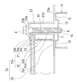
次に、上記の太陽電池装置1に用いられる架台10の取付桟11について説明する。図3は、取付桟11の外観を示した部分斜視図である。図3において、取付桟11は、断面がハット(帽子)形をした形状をしている。又、この取付桟11の天板12の上面には、取付桟11の長手方向に沿って、下方に窪んだ排水溝13が、形成されている。
Next, the mounting
又、この排水溝13の底面には、太陽電池モジュール2を固定するための螺子孔14と、桟排水孔15とが設けられている。この内、螺子孔14は、後述するように、太陽電池モジュール2を固定するのに用いられるボルト8が螺入される螺子孔である。又、桟排水孔15は、取付桟11の長手方向と直角に交差する方向に細長い形状をした貫通孔であり、後述するように、排水溝13を流れる雨水等の水を、下方外部に排出するのに用いられる。
Further, a
次に、上記の太陽電池装置1に用いられる、A太陽電池モジュール2a、及び、B太陽電池モジュール2bについて説明する。
Next, the A
まず、A太陽電池モジュール2aについて説明する。図4は、A太陽電池モジュール2aの平面図、図5は、A太陽電池モジュール2aの外観を示した部分破断斜視図である。図4、図5において、A太陽電池モジュール2aは、太陽電池パネル20と、この太陽電池パネル20を保持する枠部材21aとで構成されている。
First, the A
A太陽電池モジュール2aの枠部材21aは、太陽電池パネル20の主辺を保持する主枠部材30と、この主辺と隣接する副辺を保持する副枠部材40とを用いて、太陽電池パネル20を内側に囲むように保持している。
The
上記の主枠部材30は、主保持部31(前述の保持部に相当)、及び、主壁部32(前述の台座部に相当)で構成されている。主保持部31は、太陽電池パネルの主辺に沿って形成された主保持壁31a、該主保持壁31aの上端及び下端から内側に向かって張設された主保持上片31b、及び、主保持下片31cで構成されており、断面がコ字形で該コ字形の内部に太陽電池パネル20の主辺を上下に挟持して太陽電池パネル20を保持している。
The
主壁部32は、主保持部31の主保持下片31cの下に、内部空間33(前述の閉鎖空間に相当)を挟んで下方に伸びる主外壁32a及び主内壁32bと、これらの主外壁32a及び主内壁32bの下端で内部空間33を閉塞する主底辺32c(前述の底辺に相当)とを備えると共に、内部空間33の側端開口部が、後述する副枠部材40の副壁部42の副外壁42aの内側面に当接することにより閉塞されて、構成されている。そして、主底辺32cは、さらに内側に向かって延設されている。
The
又、主底辺32cが内部空間33を閉塞する部分には、主枠部材排水孔34(前述の台座排水孔に相当)が形成されている。この主枠部材排水孔34は、後述するように、A太陽電池モジュール2aの主枠部材30における内部空間33を流れる雨水等の水を、下方外部に排出するのに用いられる。
A main frame member drain hole 34 (corresponding to the above-described pedestal drain hole) is formed in a portion where the
又、副枠部材40は、副保持部41、及び、副壁部42で構成されている。副保持部41は、太陽電池パネル20の副辺に沿って形成された副保持壁41a、該副保持壁41aの上端及び下端から内側に向かって張設された副保持上片41b、及び、副保持下片41cで構成されており、断面がコ字形で該コ字形の内部に太陽電池パネル20の副辺を上下に挟持して太陽電池パネル20を保持している。
The
副壁部42は、副保持部41の副保持下片41cの下に、副保持壁41aの延長上に下方に伸びる副外壁42a、及び、該副外壁42aの下端から内側に向かって張設された副底辺42cで構成されている。
The
次に、B太陽電池モジュール2bについて説明する。図6は、B太陽電池モジュール2bの平面図、図7は、B太陽電池モジュール2bの外観を示した部分破断斜視図である。図6、図7において、B太陽電池モジュール2bは、太陽電池パネル20と、この太陽電池パネル20を保持する枠部材21bとで構成されている。
Next, the B
B太陽電池モジュール2bの枠部材21bは、太陽電池パネル20の主辺を保持する主枠部材50と、この主辺と隣接する副辺を保持する副枠部材60とを用いて、太陽電池パネル20を内側に囲むように保持している。
The
上記の主枠部材50は、主保持部51、及び、主壁部52で構成されている。主保持部51は、太陽電池パネル20の主辺に沿って形成された主保持壁51a、該主保持壁51aの上端及び下端から内側に向かって張設された主保持上片51b、及び、主保持下片51cで構成されており、断面がコ字形で該コ字形の内部に太陽電池パネル20の主辺を上下に挟持して太陽電池パネル20を保持している。
The
主壁部52は、主保持部51の主保持下片51cの下に、主保持壁51aの延長上に下方に伸びる主外壁52a、及び、該主外壁52aの下端から内側に向かって張設されている主底辺52cで構成されている。
The
又、上記の副枠部材60は、副保持部61(前述の保持部に相当)、及び、副壁部62(前述の台座部に相当)で構成されている。副保持部61は、太陽電池パネル20の副辺に沿って形成された副保持壁61a、該副保持壁61aの上端及び下端から内側に向かって張設された副保持上片61b、及び、副保持下片61cで構成されており、断面がコ字形で該コ字形の内部に太陽電池パネル20の副辺を上下に挟持して太陽電池パネル20を保持している。
Further, the
副壁部62は、副保持部61の副保持下片61cの下に、内部空間63(前述の閉鎖空間に相当)を挟んで下方に伸びる副外壁62a及び副内壁62bと、これらの副外壁62a及び副内壁62bの下端で内部空間63を閉塞する副底辺62c(前述の底辺に相当)とを備えると共に、内部空間63の側端開口部が、上記の主枠部材50の主壁部52の主外壁52aの内側面に当接することにより閉塞されて、構成されている。そして、副底辺62cは、さらに内側に向かって延設されている。
The sub-wall portion 62 includes a
又、副底辺62cが内部空間63を閉塞する部分で、副底辺62cの両端部には、副枠部材排水孔64(前述の台座排水孔に相当)が形成されている。この副枠部材排水孔64は、後述するように、B太陽電池モジュール2bの副枠部材60における内部空間63を流れる雨水等の水を、下方外部に排出するのに用いられる。
Further, the
本実施の形態における太陽電池装置1は、上述したように、上記のA太陽電池モジュール2aと、B太陽電池モジュール2bの2種類の太陽電池モジュールのいずれか一方が用いられており、このいずれか一方が、架台10の斜めに傾斜して配置された取付桟11に、取付られて形成される。
As described above, the
このA太陽電池モジュール2a、或いは、B太陽電池モジュール2bの取付桟11への取付は、A太陽電池モジュール2aの主枠部材30、或いは、B太陽電池モジュール2bの主枠部材50が、架台10の取付桟11の長手方向に沿うようにしてなされている。次に、これらのA太陽電池モジュール2a、及び、B太陽電池モジュール2bが、架台10の取付桟11に取付られた状態について、説明する。
The A
まず、A太陽電池モジュール2aが、架台10の取付桟11に取付られた状態について、説明する。この取付状態としては、2台の太陽電池モジュール2の端部が、太陽電池装置1の中央に配置された架台10の取付桟11に載置されて、固定金具22を用いて取付られている状態(中央取付状態と称する)と、1台の太陽電池モジュール2の端部のみが、左端又は右端に配置された架台10の取付桟11に載置されて、固定金具23を用いて取付られている状態(側部取付状態と称する)が存在する。これは、B太陽電池モジュール2bが用いられている場合も、同様である。
First, a state in which the A
そこで、最初に、A太陽電池モジュール2aが用いられている場合の中央取付状態について説明し、続いて、A太陽電池モジュール2aが用いられている場合の側部取付状態について説明する。
Therefore, first, the center mounting state when the A
まず、A太陽電池モジュール2aが用いられている場合の中央取付状態について説明する。このA太陽電池モジュール2aが用いられている場合の中央取付状態における取付けには、固定金具22が用いられる。図8は、この固定金具22の外観を示した斜視図である。
First, the center mounting state when the A
図8において、この固定金具22は、平板状の押圧板22aの前後の両端部に、下方に突出して形成される突起片22bを備えると共に、押圧板22aの中央部に、上下に貫通した押圧板孔22cを備えて形成されている。
In FIG. 8, the fixing
上記の固定金具22の押圧板22aは、後述するように、架台10の取付桟11の天板12上に、離間して隣接して配置される2個の太陽電池モジュール2aの端部に備えられた枠部材21aを、上から押圧するのに用いられる。又、押圧板孔22cは、ボルト8が挿入される孔である。
As will be described later, the
又、固定金具22の突起片22bは、離間して隣接して配置される2個の上記の太陽電池モジュール2aの対面する端部に、共に備えられている枠部材21aの相互間に形成される隙間7に、挿入される。
Further, the protruding
図9は、A太陽電池モジュール2aが用いられている場合の中央取付状態を示した部分斜視図、図10は、部分破断斜視図、そして、図11は、中央取付状態における取付部分の断面図である。図9〜図11において、A太陽電池モジュール2aが用いられている場合の中央取付状態は、次のようにして形成される。
9 is a partial perspective view showing a central mounting state when the A
まず、架台10の取付桟11の天板12の上に、2個のA太陽電池モジュール2aを、該A太陽電池モジュール2aの枠部材21aの端部である主枠部材30が、架台10の取付桟11の長手方向に沿うようにして、離間して隣接して載置する。
First, two A
この際、図10に示すように、主枠部材30の主壁部32の主底辺32cに備えられている主枠部材排水孔34から、雨水等の水が、架台10の取付桟11の排水溝13に流れ落ちるように、主枠部材排水孔34の開口下端が、排水溝13の上に位置するようにして、A太陽電池モジュール2aの主枠部材30の主壁部32の主底辺32cを、取付桟11の天板12の上面に載置する。
At this time, as shown in FIG. 10, water such as rainwater is drained from the mounting
次に、2個のA太陽電池モジュール2aの枠部材21aの端部の上に、固定金具22を設置する。即ち、図9〜図11において、固定金具22の押圧板22aを、隣接する2個の太陽電池モジュール2aの端部に備えられた枠部材21aの間に形成されている隙間7を左右方向に跨ぐようにする。
Next, the fixing metal fitting 22 is installed on the edge part of the
そして、固定金具22の突起片22bを、隣接する2個のA太陽電池モジュール2aの対面する端部に備えられた枠部材21a間に形成されている隙間7に、上方から挿入する。そして、この2個のA太陽電池モジュール2aの端部を、固定金具22の押圧板22aにより、上から押圧すると共に、ボルト8を、固定金具22の押圧板孔22cへ挿入して、架台10の取付桟11の排水溝13の底面に設けられている螺子孔14へ螺入して、締付て固定する。
Then, the protruding
上記の太陽電池装置1におけるA太陽電池モジュール2aが用いられている場合の中央取付状態では、A太陽電池モジュール2aの主枠部材30の主壁部32は、主底辺32c、及び、該主底辺32cの内側面を構成要素とする閉鎖空間である内部空間33を備えており、一種の角パイプに近い構造で形成することが可能である。
In the center mounting state when the A
そのため、A太陽電池モジュール2aの主壁部32の強度の増加を図ることができると共に、この主壁部32の内部に、内部空間33が形成されることから、主壁部32の重量増加を抑制することができる。従って、A太陽電池モジュール2aの強度の増加を図ることができると共に、重量増加を抑制することができる。
Therefore, the strength of the
又、A太陽電池モジュール2aの主壁部32の内部空間33の主底辺32cに、内部空間33に滞留する雨水等の水(滞留水)を下方側外部に排出する主枠部材排水孔34が備えられている。又、上下方向に斜めに傾斜して配設される架台10の取付桟11には、該取付桟11の上面に、該取付桟11の長手方向に沿って、下方に窪んだ排水溝13が備えられている。
Further, a main frame
又、主壁部32の内部空間33の主底辺32cに備えられた主枠部材排水孔34から、上記の滞留水が架台10の取付桟11の排水溝13に流れ落ちるように、主枠部材排水孔34の開口下端が、上記の架10台の取付桟11に備えられた排水溝13の上に位置するようにして、A太陽電池モジュール2aが該架台10に支持されている。
Further, the main frame member drainage is performed so that the accumulated water flows from the main frame
さらに、上下方向に斜めに傾斜して配設される架台10の取付桟11の排水溝13には、該排水溝13に流れ落ちて該排水溝13を流れる滞留水を、下方外部に排出する桟排水孔15が、備えられている。
Further, in the
そのため、A太陽電池モジュール2aの主枠部材30の主壁部32の内部空間33に滞留する雨水等の滞留水を、主壁部32の主底辺32cの主枠部材排水孔34から架台10の取付桟11の排水溝13へ排出することが、容易にできる。
Therefore, stagnant water such as rainwater that stays in the
さらに、A太陽電池モジュール2aの主枠部材30の主壁部32の内部空間33に滞留する雨水等の滞留水を、主壁部32の主底辺32cの主枠部材排水孔34から、架台10の取付桟11の排水溝13に流れ落ちて該排水溝13を流れる上記の滞留水を、架台10の取付桟11の排水溝13の桟排水孔15により、容易に下方外部に排出することができる。
Further, the accumulated water such as rainwater staying in the
従って、上記の太陽電池装置1におけるA太陽電池モジュール2aの主枠部材30の主壁部32の内部空間33に滞留する雨水等の滞留水が、寒冷地における厳寒期等に凍ることによりA太陽電池モジュール2aが破壊されることを、防止することができる。
Accordingly, the accumulated water such as rainwater that stays in the
次に、A太陽電池モジュール2aが用いられている場合の側部取付状態について説明する。このA太陽電池モジュール2aが用いられている場合の側部取付状態における取付けには、固定金具23が用いられる。図12は、この固定金具23の外観を示した斜視図である。
Next, the side part attachment state in case A
図12において、この固定金具23は、平板状の押圧板23aと、該押圧板23aの前後の両端部が下方に屈曲して形成された突起片23bと、押圧板23aの中央部に、上下に貫通した押圧板孔23cと、該押圧板23aの左右の両端部の内、太陽電池モジュール2が存在しない側の端部に下方に向かって垂設された立壁23d、及び、該立壁23dの下端に、押圧板23aの存在する側と反対の側に横向きに垂設された底部片23eとで構成される。
In FIG. 12, this fixing
上記の固定金具23の押圧板23aは、架台10の取付桟11の天板12上に配置される1個の太陽電池モジュール2aの端部に備えられた枠部材21aを、上から押圧するのに用いられる。又、押圧板孔23cは、ボルト8が挿入される孔である。
The
又、固定金具23の突起片23bは、1個の上記の太陽電池モジュール2aの枠部材21aと固定金具23の立壁23dとの間に形成される隙間7に、挿入される。
Further, the protruding
図13は、A太陽電池モジュール2aが用いられている場合の側部取付状態を示した断面図である。即ち、この側部取付状態では、上述した中央取付状態を示した図11において、固定金具22、及び、右側のA太陽電池モジュール2aに代えて、固定金具23を使用する。
FIG. 13 is a cross-sectional view showing a side attachment state when the A
そこで、A太陽電池モジュール2aが用いられている場合の側部取付状態は、次のようにして形成される。即ち、図13において、まず、架台10の取付桟11の天板12の上に、図13に示す左側の1個のA太陽電池モジュール2aを、該A太陽電池モジュール2aの枠部材21aの端部である主枠部材30が、架台10の取付桟11の長手方向に沿うようにして、載置する。
Then, the side part attachment state in case A
この際、A太陽電池モジュール2aが用いられている場合の中央取付状態におけるのと同様に、図10に示すように、主枠部材30の主壁部32の主底辺32cに備えられている主枠部材排水孔34から、雨水等の水が、架台10の取付桟11の排水溝13に流れ落ちるように、主枠部材排水孔34の開口下端が、排水溝13の上に位置するようにして、A太陽電池モジュール2aの主枠部材30の主壁部32の主底辺32cを、取付桟11の天板12の上面に載置する。
At this time, as shown in FIG. 10, the
そして、固定金具23を図13に示すように設置して、左側の1個のA太陽電池モジュール2aの端部を、固定金具23の押圧板23aにより、上から押圧すると共に、ボルト8を、固定金具23の押圧板孔23cへ挿入して、架台10の取付桟11の排水溝13の底面に設けられている螺子孔14へ螺入して、締付て固定する。
Then, the fixing
上記のA太陽電池モジュール2aが用いられている場合の側部取付状態は、上述したA太陽電池モジュール2aが用いられている場合の中央取付状態と、基本的な構造が、略同じである。従って、上記の太陽電池装置1におけるA太陽電池モジュール2aが用いられている場合の側部取付状態においても、上述した中央取付状態と同様の作用、効果を有する。
The side attachment state when the A
次に、B太陽電池モジュール2bが用いられている場合の中央取付状態について説明する。このB太陽電池モジュール2bが用いられた中央取付状態においても、上記のA太陽電池モジュール2aが用いられた場合と同様、固定金具22が用いられる。
Next, the center mounting state when the B
図14は、B太陽電池モジュール2bが用いられている場合の中央取付状態を示した部分斜視図、図15は、部分破断斜視図、そして、図16は、中央取付状態における取付部分の断面図である。図14〜図16において、B太陽電池モジュール2bが用いられている場合の中央取付状態は、次のようにして形成される。
14 is a partial perspective view showing a central mounting state when the B
まず、架台10の取付桟11の天板12の上に、2個のB太陽電池モジュール2bを、該B太陽電池モジュール2bの枠部材21bの端部である主枠部材50が、架台10の取付桟11の長手方向に沿うようにして、離間して隣接して載置する。
First, two B
この際、図15に示すように、副枠部材60の副壁部62の副底辺62cに備えられている副枠部材排水孔64から、雨水等の水が、架台10の取付桟11の排水溝13に流れ落ちるように、副枠部材排水孔64の開口下端が、排水溝13の上に位置するようにして、B太陽電池モジュール2bの主枠部材50の主壁部52の主底辺52cを、取付桟11の天板12の上面に載置する。
At this time, as shown in FIG. 15, water such as rainwater is drained from the mounting
次に、2個のB太陽電池モジュール2bの枠部材21bの端部の上に、固定金具22を設置する。即ち、図4〜図16において、固定金具22の押圧板22aを、隣接する2個の太陽電池モジュール2bの端部に備えられた枠部材21bの間に形成されている隙間7を左右方向に跨ぐようにする。
Next, the fixing
そして、固定金具22の突起片22bが、隣接する2個のB太陽電池モジュール2bの対面する端部に備えられた枠部材21b間に形成されている隙間7に、上方から挿入する。そして、この2個のB太陽電池モジュール2bの端部を、固定金具22の押圧板22aにより、上から押圧すると共に、ボルト8を、固定金具22の押圧板孔22cへ挿入して、架台10の取付桟11の排水溝13の底面に設けられている螺子孔14へ螺入して、締付て固定する。
And the
上記のB太陽電池モジュール2bが用いられている場合の中央取付状態では、B太陽電池モジュール2bの副枠部材60の副壁部62は、副底辺62c、及び、該副底辺62cの内側面を構成要素とする閉鎖空間である内部空間63を備えており、一種の角パイプに近い構造で形成することが可能である。
In the center mounting state when the above B
そのため、上記の太陽電池装置1におけるB太陽電池モジュール2bの副壁部62の強度の増加を図ることができると共に、この副壁部62の内部に、内部空間63が形成されることから、副壁部62の重量増加を抑制することができる。従って、B太陽電池モジュール2bの強度の増加を図ることができると共に、重量増加を抑制することができる。
Therefore, the strength of the sub wall 62 of the B
又、上記の太陽電池装置1では、B太陽電池モジュール2bの副壁部62の内部空間63の副底辺62cに、内部空間63に滞留する雨水等の水(滞留水)を下方側外部に排出する副枠部材排水孔64が備えられている。又、上下方向に斜めに傾斜して配設される架台10の取付桟11には、該取付桟11の上面に、該取付桟11の長手方向に沿って、下方に窪んだ排水溝13が備えられている。
Further, in the
又、上記のB太陽電池モジュール2bが用いられている場合の中央取付状態では、副壁部62の内部空間63の副底辺62cに備えられた副枠部材排水孔64から、上記の滞留水が架台10の取付桟11の排水溝13に流れ落ちるように、副枠部材排水孔64の開口下端が、上記の架10台の取付桟11に備えられた排水溝13の上に位置するようにして、B太陽電池モジュール2bが該架台10に支持されている。
Further, in the central mounting state when the B
さらに、上下方向に斜めに傾斜して配設される架台10の取付桟11の排水溝13には、該排水溝13に流れ落ちて該排水溝13を流れる滞留水を、下方外部に排出する桟排水孔15が、備えられている。
Further, in the
そのため、B太陽電池モジュール2bの副枠部材60の主壁部62の内部空間63に滞留する雨水等の滞留水を、副壁部62の主底辺62cの副枠部材排水孔64から架台10の取付桟11の排水溝13へ排出することが、容易にできる。
Therefore, stagnant water such as rainwater that stays in the
さらに、B太陽電池モジュール2bの副枠部材60の副壁部62の内部空間63に滞留する雨水等の滞留水を、副壁部62の副底辺62cの副枠部材排水孔64から、架台10の取付桟11の排水溝13に流れ落ちて該排水溝13を流れる上記の滞留水を、架台10の取付桟11の排水溝13の桟排水孔15により、容易に下方外部に排出することができる。
Further, the accumulated water such as rain water staying in the
従って、B太陽電池モジュール2bの副枠部材60の副壁部62の内部空間63に滞留する雨水等の滞留水が、寒冷地における厳寒期等に凍ることによりB太陽電池モジュール2bが破壊されることを、防止することができる。
Therefore, the B
次に、B太陽電池モジュール2bが用いられている場合の側部取付状態について説明する。このB太陽電池モジュール2bが用いられた側部取付状態においても、上記のA太陽電池モジュール2aが用いられた場合と同様、固定金具23が用いられる。
Next, the side attachment state when the B
図17は、B太陽電池モジュール2bが用いられている場合の側部取付状態を示した断面図である。即ち、この側部取付状態では、上述した中央取付状態を示した図16において、固定金具22、及び、右側のB太陽電池モジュール2bに代えて、固定金具23を使用する。
FIG. 17 is a cross-sectional view showing a side attachment state when the B
そこで、B太陽電池モジュール2bが用いられている場合の側部取付状態は、次のようにして形成される。即ち、図17において、まず、架台10の取付桟11の天板12の上に、図17に示す左側の1個のB太陽電池モジュール2bを、該B太陽電池モジュール2bの枠部材21bの端部である主枠部材50が、架台10の取付桟11の長手方向に沿うようにして、載置する。
Then, the side part attachment state in case B
この際、B太陽電池モジュール2bが用いられている場合の中央取付状態におけるのと同様に、図15に示すように、副枠部材60の副壁部62の副底辺62cに備えられている副枠部材排水孔64から、雨水等の水が、架台10の取付桟11の排水溝13に流れ落ちるように、副枠部材排水孔64の開口下端が、排水溝13の上に位置するようにして、B太陽電池モジュール2bの主枠部材50の主壁部52の主底辺52cを、取付桟11の天板12の上面に載置する。
At this time, as shown in FIG. 15, the sub-base provided on the sub-bottom 62 c of the sub-wall portion 62 of the
そして、固定金具23を図17に示すように設置して、左側の1個のB太陽電池モジュール2bの端部を、固定金具23の押圧板23aにより、上から押圧すると共に、ボルト8を、固定金具23の押圧板孔23cへ挿入して、架台10の取付桟11の排水溝13の底面に設けられている螺子孔14へ螺入して、締付て固定する。
Then, the fixing
上記のB太陽電池モジュール2bが用いられている場合の側部取付状態は、上述したB太陽電池モジュール2bが用いられている場合の中央取付状態と、基本的な構造が、略同じである。従って、上記の太陽電池装置1におけるB太陽電池モジュール2bが用いられている場合の側部取付状態においても、上述した中央取付状態と同様の作用、効果を有する。
The side attachment state when the above-described B
上述した説明では、太陽電池装置1には、図4、図5に示す構成のA太陽電池モジュール2a、又は、図6、図7に示す構成のB太陽電池モジュール2bが用いられている。これに対して、太陽電池モジュールとして、図18に示すように、主壁部32の主外壁32aから外側に突出すると共に、先端が上方に屈曲して堤壁36を形成した鉤片35が備えられている枠部材21cを使用したC太陽電池モジュール2cを用いて、上述したような太陽電池装置1を構成することもできる。この場合におけるC太陽電池モジュール2cにおける中央取付状態について、次に説明する。
In the above description, the
この鉤片35を備えた枠部材21cを用いた場合のC太陽電池モジュール2cにおける中央取付状態では、C太陽電池モジュール2cとしては、上述したように、C太陽電池モジュール2cの枠部材21cの主外壁32aに、該主外壁32aから外側に突出すると共に先端が上方に屈曲して堤壁36を形成した鉤片35が備えられている。
In the center mounting state in the C
このようなC太陽電池モジュール2cを用いた太陽電池装置1における中央取付状態では、図19に示すように、C太陽電池モジュール2cにおける双方の鉤片25の堤壁26間に形成されている隙間7を、固定金具22の押圧板22aで、左右方向に跨ぐと共に、C太陽電池モジュール2cにおける鉤片25の堤壁26の上端面を、上から押圧するようにする。
In the center mounting state in the
そして、さらに、固定金具22の突起片22bは、C太陽電池モジュール2cにおける鉤片25の堤壁26間に形成されている隙間7に挿入されるようにするのである。
Further, the protruding
上記の鉤片を備えた枠部材を用いた場合の太陽電池装置1のC太陽電池モジュール2cにおける中央取付状態は、上述した中央取付状態と、基本的な構造が、略同じである。従って、上記の鉤片25を備えた枠部材21cを用いた場合の太陽電池装置1のC太陽電池モジュール2cにおける中央取付状態においても、上述した中央取付状態と同様の作用、効果を有する。この点は、側部取付状態においても、同様である。
The center attachment state in the C
又、上記の本実施の形態における太陽電池モジュール取付構造を採用した太陽電池装置1は、図1に示すように、太陽電池装置1の左端、右端、及び、中央の各部分に相当する位置に、相互に平行に配置された3台の架台10を用いて、4個の太陽電池モジュール2を取付ている。
In addition, the
しかし、本実施の形態における太陽電池モジュール取付構造を採用した太陽電池装置1は、これには限られず、例えば、図1において、相互に平行に配置された架台10の台数をさらに増やすことによって、或いは、架台10の取付桟11の長さが、さらに長い取付桟を用いた架台を使用することによって、取付可能な太陽電池モジュール2を、増加することができる。
However, the
以上のように、発明を実施するための形態について、一例を挙げて述べてきたが、架台10は斜めに傾斜して配置された取付桟11を有する代わりに、傾斜屋根に直接配置された取付桟11を有してもよく、取付桟11は傾斜しなく陸屋根などの水平面に設置されてもよい。又、取付桟11の長手方向が傾斜する方向でなくてもよく、例えば傾斜屋根に対して、流れ方向と直交するように設置されてもよい。
As described above, the embodiment for carrying out the invention has been described with an example. However, the
1 太陽電池装置
2 太陽電池モジュール
2a A太陽電池モジュール
2b B太陽電池モジュール
2c C太陽電池モジュール
7 隙間
8 ボルト
10 架台
11 取付桟
12 天板
13 排水溝
14 螺子孔
15 桟排水孔
16 縦桟
20 太陽電池パネル
21 枠部材
21a 枠部材
21b 枠部材
21c 枠部材
22 固定金具
22a 押圧板
22b 突起片
22c 押圧板孔
23 固定金具
23a 押圧板
23b 突起片
23c 押圧板孔
23d 立壁
23e 底部片
30 主枠部材
31 主保持部
31a 主保持壁
31b 主保持上片
31c 主保持下片
32 主壁部
32a 主外壁
32b 主内壁
32c 主底辺
33 内部空間
34 主枠部材排水孔
35 鉤片
36 堤壁
36a 堤壁の上端面
40 副枠部材
41 副保持部
41a 副保持壁
41b 副保持上片
41c 副保持下片
42a 副外壁
42c 副底辺
50 主枠部材
51 主保持部
51a 主保持壁
51b 主保持上片
51c 主保持下片
52 主壁部
52a 主外壁
52c 主底辺
60 副枠部材
61 副保持部
61a 副保持壁
61b 副保持上片
61c 副保持下片
62 副壁部
62a 副外壁
62b 副内壁
62c 副底辺
63 内部空間
64 副枠部材排水孔
DESCRIPTION OF SYMBOLS 1 Solar cell apparatus 2 Solar cell module 2a A solar cell module 2b B solar cell module 2c C solar cell module 7 Gap 8 Bolt 10 Mounting frame 11 Mounting bar 12 Top plate 13 Drain groove 14 Screw hole 15 Bar drain hole 16 Vertical beam 20 Sun Battery panel 21 Frame member 21a Frame member 21b Frame member 21c Frame member 22 Fixing bracket 22a Press plate 22b Projection piece 22c Press plate hole 23 Fixing bracket 23a Press plate 23b Projection piece 23c Press plate hole 23d Standing wall 23e Bottom piece 30 Main frame member 31 Main holding portion 31a Main holding wall 31b Main holding upper piece 31c Main holding lower piece 32 Main wall portion 32a Main outer wall 32b Main inner wall 32c Main bottom 33 Internal space 34 Main frame member drainage hole 35 Grain piece 36 Dyke wall 36a End face 40 Sub-frame member 41 Sub-holding part 41a Sub-holding wall 41b Sub-holding top 41c Sub-holding lower piece 42a Sub-outer wall 42c Sub-bottom side 50 Main frame member 51 Main holding portion 51a Main holding wall 51b Main holding upper piece 51c Main holding lower piece 52 Main wall portion 52a Main outer wall 52c Main bottom side 60 Sub-frame member 61 Sub-holding Part 61a Sub holding wall 61b Sub holding upper piece 61c Sub holding lower piece 62 Sub wall part 62a Sub outer wall 62b Sub inner wall 62c Sub base 63 Internal space 64 Sub frame member drain hole
Claims (4)
前記太陽電池モジュールの少なくとも一部の前記台座部は、底辺、及び、該底辺の内側面を構成要素とする閉鎖空間を備えており、該底辺には、該閉鎖空間に滞留する雨水等の滞留水を下方外部に排出する台座排水孔を備えていると共に、
前記架台の取付桟は、該取付桟の上面に、該取付桟の長手方向に沿って、下方に窪んだ排水溝を備えており、
前記太陽電池モジュールの前記台座部の底辺に備えられた前記台座排水孔から、前記滞留水が前記架台の取付桟の排水溝に流れ落ちるように、前記台座排水孔の開口下端が、前記排水溝の上に位置するようにして、前記太陽電池モジュールの台座部の底辺が前記取付桟の上面に載置されていることを特徴とする太陽電池装置。 A solar cell module composed of a rectangular solar cell panel, a holding unit that sandwiches and holds the periphery of the solar cell panel, and a pedestal unit provided below the holding unit, in a vertical direction A solar cell device that is supported by a gantry provided with a mounting bar disposed obliquely at
The pedestal portion of at least a part of the solar cell module includes a closed space having a bottom side and an inner side surface of the bottom side as constituent elements, and the bottom side retains rainwater or the like remaining in the closed space. It has a pedestal drainage hole that discharges water to the outside,
The mounting frame of the gantry includes a drainage groove that is recessed downward along the longitudinal direction of the mounting frame on the upper surface of the mounting frame.
The lower open end of the pedestal drainage hole is formed in the drainage groove so that the accumulated water flows down from the pedestal drainage hole provided at the bottom of the pedestal part of the solar cell module to the drainage groove of the mounting frame of the gantry. A solar cell device, wherein the bottom side of the pedestal of the solar cell module is placed on the upper surface of the mounting bar so as to be positioned above.
前記架台の取付桟の排水溝は、該排水溝に流れ落ちて該排水溝を流れる前記滞留水を下方外部に排出する桟排水孔を、該排水溝の底面に備えている太陽電池装置。 The solar cell device according to claim 1, wherein
The drainage groove of the mounting rail of the gantry includes a drainage hole on the bottom surface of the drainage groove, which drains the accumulated water flowing down to the drainage groove and discharging the accumulated water downward.
前記台座排水孔を備えた前記閉鎖空間が備えられている前記太陽電池モジュールの台座部は、前記取付桟の長手方向に沿って、該取付桟に載置されている太陽電池装置。 In the solar cell device according to claim 1 or 2,
The solar cell device in which the pedestal part of the solar cell module provided with the closed space provided with the pedestal drain hole is placed on the mounting bar along the longitudinal direction of the mounting bar.
前記台座排水孔を備えた前記閉鎖空間が備えられている前記太陽電池モジュールの台座部は、前記取付桟の長手方向と直交する方向に沿って、該取付桟に載置されていると共に、
前記太陽電池モジュールの台座部の底辺に備えられている前記台座排水孔は、該底辺の両端部に備えられている太陽電池装置。 In the solar cell device according to claim 1 or 2,
The pedestal portion of the solar cell module provided with the closed space provided with the pedestal drain hole is placed on the mounting bar along a direction orthogonal to the longitudinal direction of the mounting bar,
The pedestal drain hole provided in the bottom side of the pedestal portion of the solar cell module is a solar cell device provided in both end portions of the bottom side.
Priority Applications (1)
| Application Number | Priority Date | Filing Date | Title |
|---|---|---|---|
| JP2008250507A JP4979665B2 (en) | 2008-09-29 | 2008-09-29 | Solar cell device |
Applications Claiming Priority (1)
| Application Number | Priority Date | Filing Date | Title |
|---|---|---|---|
| JP2008250507A JP4979665B2 (en) | 2008-09-29 | 2008-09-29 | Solar cell device |
Publications (2)
| Publication Number | Publication Date |
|---|---|
| JP2010080872A true JP2010080872A (en) | 2010-04-08 |
| JP4979665B2 JP4979665B2 (en) | 2012-07-18 |
Family
ID=42210932
Family Applications (1)
| Application Number | Title | Priority Date | Filing Date |
|---|---|---|---|
| JP2008250507A Expired - Fee Related JP4979665B2 (en) | 2008-09-29 | 2008-09-29 | Solar cell device |
Country Status (1)
| Country | Link |
|---|---|
| JP (1) | JP4979665B2 (en) |
Cited By (7)
| Publication number | Priority date | Publication date | Assignee | Title |
|---|---|---|---|---|
| KR101179894B1 (en) | 2010-09-30 | 2012-09-06 | 주식회사 성일메디팜 | Deferment unit assembly for supporting module of solar battery |
| JP2013232686A (en) * | 2011-08-08 | 2013-11-14 | Sankyotateyama Inc | Solar battery panel body |
| WO2013168440A1 (en) * | 2012-05-11 | 2013-11-14 | 京セラ株式会社 | Solar cell apparatus |
| ITVI20120205A1 (en) * | 2012-08-07 | 2014-02-08 | Giovanni Bianchini | MODULAR SUPPORT STRUCTURE FOR A SOLAR ENERGY SYSTEM. |
| KR101704588B1 (en) * | 2016-05-19 | 2017-02-08 | 주식회사 이엠테크 | Solar frames and railing installation structure provided for this module |
| JP6487590B1 (en) * | 2018-06-12 | 2019-03-20 | 株式会社Katoホールディングス | Solar house |
| JP2019216521A (en) * | 2018-06-12 | 2019-12-19 | 株式会社Katoホールディングス | Solar panel frame |
Citations (11)
| Publication number | Priority date | Publication date | Assignee | Title |
|---|---|---|---|---|
| JPH10169127A (en) * | 1996-12-09 | 1998-06-23 | Misawa Homes Co Ltd | Solar energy converter |
| JPH10190035A (en) * | 1996-12-27 | 1998-07-21 | Gantan Beauty Kogyo Kk | Solar cell panel and roof structure using the solar cell panel |
| JPH11324246A (en) * | 1998-05-20 | 1999-11-26 | Misawa Homes Co Ltd | Support rail for solar panel and solar panel mounting structure |
| JP2001123609A (en) * | 1999-10-27 | 2001-05-08 | Mitsubishi Electric Corp | Solar battery panel and roof structure with solar battery panel |
| JP2001140427A (en) * | 1999-11-12 | 2001-05-22 | Misawa Homes Co Ltd | Solar battery panel |
| JP2003221906A (en) * | 2002-01-30 | 2003-08-08 | Mitsubishi Heavy Ind Ltd | Pedestal for solar battery panel |
| JP2003282919A (en) * | 2002-03-27 | 2003-10-03 | Kyocera Corp | Solar cell module |
| JP2003282912A (en) * | 2002-03-25 | 2003-10-03 | Canon Inc | Base material aggregate with electric parts and solar light generating system |
| JP2004281801A (en) * | 2003-03-17 | 2004-10-07 | Kyocera Corp | Solar cell module |
| JP2006269610A (en) * | 2005-03-23 | 2006-10-05 | Canon Inc | Solar cell module and method of installing the same |
| WO2009119775A1 (en) * | 2008-03-26 | 2009-10-01 | 京セラ株式会社 | Solar cell module |
-
2008
- 2008-09-29 JP JP2008250507A patent/JP4979665B2/en not_active Expired - Fee Related
Patent Citations (11)
| Publication number | Priority date | Publication date | Assignee | Title |
|---|---|---|---|---|
| JPH10169127A (en) * | 1996-12-09 | 1998-06-23 | Misawa Homes Co Ltd | Solar energy converter |
| JPH10190035A (en) * | 1996-12-27 | 1998-07-21 | Gantan Beauty Kogyo Kk | Solar cell panel and roof structure using the solar cell panel |
| JPH11324246A (en) * | 1998-05-20 | 1999-11-26 | Misawa Homes Co Ltd | Support rail for solar panel and solar panel mounting structure |
| JP2001123609A (en) * | 1999-10-27 | 2001-05-08 | Mitsubishi Electric Corp | Solar battery panel and roof structure with solar battery panel |
| JP2001140427A (en) * | 1999-11-12 | 2001-05-22 | Misawa Homes Co Ltd | Solar battery panel |
| JP2003221906A (en) * | 2002-01-30 | 2003-08-08 | Mitsubishi Heavy Ind Ltd | Pedestal for solar battery panel |
| JP2003282912A (en) * | 2002-03-25 | 2003-10-03 | Canon Inc | Base material aggregate with electric parts and solar light generating system |
| JP2003282919A (en) * | 2002-03-27 | 2003-10-03 | Kyocera Corp | Solar cell module |
| JP2004281801A (en) * | 2003-03-17 | 2004-10-07 | Kyocera Corp | Solar cell module |
| JP2006269610A (en) * | 2005-03-23 | 2006-10-05 | Canon Inc | Solar cell module and method of installing the same |
| WO2009119775A1 (en) * | 2008-03-26 | 2009-10-01 | 京セラ株式会社 | Solar cell module |
Cited By (11)
| Publication number | Priority date | Publication date | Assignee | Title |
|---|---|---|---|---|
| KR101179894B1 (en) | 2010-09-30 | 2012-09-06 | 주식회사 성일메디팜 | Deferment unit assembly for supporting module of solar battery |
| JP2013232686A (en) * | 2011-08-08 | 2013-11-14 | Sankyotateyama Inc | Solar battery panel body |
| WO2013168440A1 (en) * | 2012-05-11 | 2013-11-14 | 京セラ株式会社 | Solar cell apparatus |
| JPWO2013168440A1 (en) * | 2012-05-11 | 2016-01-07 | 京セラ株式会社 | Solar cell device |
| ITVI20120205A1 (en) * | 2012-08-07 | 2014-02-08 | Giovanni Bianchini | MODULAR SUPPORT STRUCTURE FOR A SOLAR ENERGY SYSTEM. |
| EP2696151A3 (en) * | 2012-08-07 | 2014-11-19 | Giovanni Bianchini | Modular supporting structure for a solar energy system. |
| KR101704588B1 (en) * | 2016-05-19 | 2017-02-08 | 주식회사 이엠테크 | Solar frames and railing installation structure provided for this module |
| JP6487590B1 (en) * | 2018-06-12 | 2019-03-20 | 株式会社Katoホールディングス | Solar house |
| JP2019214850A (en) * | 2018-06-12 | 2019-12-19 | 株式会社Katoホールディングス | Solar house |
| JP2019216521A (en) * | 2018-06-12 | 2019-12-19 | 株式会社Katoホールディングス | Solar panel frame |
| WO2019239740A1 (en) * | 2018-06-12 | 2019-12-19 | 株式会社Katoホールディングス | Solar panel mount |
Also Published As
| Publication number | Publication date |
|---|---|
| JP4979665B2 (en) | 2012-07-18 |
Similar Documents
| Publication | Publication Date | Title |
|---|---|---|
| JP4979665B2 (en) | Solar cell device | |
| US20110120529A1 (en) | Solar cell module | |
| KR20150018341A (en) | Supporting Device for Solar Panel | |
| RU2012147342A (en) | DECK RATTER ASSY | |
| JP2009041286A (en) | Structure installation frame, method of assembling the same, solar battery module, and construction structure using the structure installation frame | |
| WO2012107711A4 (en) | Solar panel apparatus and assemblies | |
| JP2007309039A (en) | Wiring housing structure for object to be installed on roof | |
| RU2017102411A (en) | FASTENING ELEMENT FOR OUTDOOR ELEMENTS AND EXTERNAL DESIGN | |
| JP5388880B2 (en) | Solar cell module fixing structure, solar cell module mount, solar cell module construction method, and solar cell power generation system | |
| JP6441041B2 (en) | Solar panel mount | |
| JP2011117204A (en) | Draining structure for solar cell module | |
| JP3194299U (en) | Support panel for solar panel | |
| WO2013099028A1 (en) | Photovoltatic power module | |
| JP5475562B2 (en) | Solar cell mounting structure | |
| KR101826395B1 (en) | Sound Proof Tunnel Using Truss Type Roof Frame | |
| KR101082871B1 (en) | casette for loding LCD glass | |
| JP5938826B2 (en) | Solar panel installation structure and solar panel installation construction method | |
| JP2015059372A (en) | Fence | |
| KR101409661B1 (en) | Puzzle type noise barrier installation structure | |
| JP2013076307A (en) | Photovoltaic power generation device and installation method thereof | |
| JP6670152B2 (en) | Roof installation panel | |
| EP2456927A1 (en) | Transportable sealed device containing a space consisting of thermoacoustic insulating walls for providing architectural and transport spaces | |
| KR100649455B1 (en) | Road sound insulation | |
| KR102438008B1 (en) | Prefabricated roof panel structure | |
| JP3145268U (en) | Long starter for mounting outer wall materials |
Legal Events
| Date | Code | Title | Description |
|---|---|---|---|
| A621 | Written request for application examination |
Free format text: JAPANESE INTERMEDIATE CODE: A621 Effective date: 20100826 |
|
| A977 | Report on retrieval |
Free format text: JAPANESE INTERMEDIATE CODE: A971007 Effective date: 20111130 |
|
| A131 | Notification of reasons for refusal |
Free format text: JAPANESE INTERMEDIATE CODE: A131 Effective date: 20111206 |
|
| A521 | Request for written amendment filed |
Free format text: JAPANESE INTERMEDIATE CODE: A523 Effective date: 20120206 |
|
| RD02 | Notification of acceptance of power of attorney |
Free format text: JAPANESE INTERMEDIATE CODE: A7422 Effective date: 20120206 |
|
| TRDD | Decision of grant or rejection written | ||
| A01 | Written decision to grant a patent or to grant a registration (utility model) |
Free format text: JAPANESE INTERMEDIATE CODE: A01 Effective date: 20120327 |
|
| A01 | Written decision to grant a patent or to grant a registration (utility model) |
Free format text: JAPANESE INTERMEDIATE CODE: A01 |
|
| A61 | First payment of annual fees (during grant procedure) |
Free format text: JAPANESE INTERMEDIATE CODE: A61 Effective date: 20120417 |
|
| FPAY | Renewal fee payment (event date is renewal date of database) |
Free format text: PAYMENT UNTIL: 20150427 Year of fee payment: 3 |
|
| R150 | Certificate of patent or registration of utility model |
Free format text: JAPANESE INTERMEDIATE CODE: R150 |
|
| LAPS | Cancellation because of no payment of annual fees |