JP2009527006A - Fiber distribution hub with externally accessible ground terminal - Google Patents
Fiber distribution hub with externally accessible ground terminal Download PDFInfo
- Publication number
- JP2009527006A JP2009527006A JP2008554320A JP2008554320A JP2009527006A JP 2009527006 A JP2009527006 A JP 2009527006A JP 2008554320 A JP2008554320 A JP 2008554320A JP 2008554320 A JP2008554320 A JP 2008554320A JP 2009527006 A JP2009527006 A JP 2009527006A
- Authority
- JP
- Japan
- Prior art keywords
- cable
- cabinet
- distribution hub
- ground
- fiber
- Prior art date
- Legal status (The legal status is an assumption and is not a legal conclusion. Google has not performed a legal analysis and makes no representation as to the accuracy of the status listed.)
- Pending
Links
Images


Classifications
-
- G—PHYSICS
- G02—OPTICS
- G02B—OPTICAL ELEMENTS, SYSTEMS OR APPARATUS
- G02B6/00—Light guides; Structural details of arrangements comprising light guides and other optical elements, e.g. couplings
- G02B6/44—Mechanical structures for providing tensile strength and external protection for fibres, e.g. optical transmission cables
- G02B6/4439—Auxiliary devices
- G02B6/444—Systems or boxes with surplus lengths
- G02B6/4441—Boxes
- G02B6/4446—Cable boxes, e.g. splicing boxes with two or more multi fibre cables
-
- G—PHYSICS
- G02—OPTICS
- G02B—OPTICAL ELEMENTS, SYSTEMS OR APPARATUS
- G02B6/00—Light guides; Structural details of arrangements comprising light guides and other optical elements, e.g. couplings
- G02B6/44—Mechanical structures for providing tensile strength and external protection for fibres, e.g. optical transmission cables
- G02B6/4439—Auxiliary devices
- G02B6/444—Systems or boxes with surplus lengths
- G02B6/4452—Distribution frames
- G02B6/44524—Distribution frames with frame parts or auxiliary devices mounted on the frame and collectively not covering a whole width of the frame or rack
-
- G—PHYSICS
- G02—OPTICS
- G02B—OPTICAL ELEMENTS, SYSTEMS OR APPARATUS
- G02B6/00—Light guides; Structural details of arrangements comprising light guides and other optical elements, e.g. couplings
- G02B6/44—Mechanical structures for providing tensile strength and external protection for fibres, e.g. optical transmission cables
- G02B6/4439—Auxiliary devices
- G02B6/444—Systems or boxes with surplus lengths
- G02B6/44528—Patch-cords; Connector arrangements in the system or in the box
-
- G—PHYSICS
- G02—OPTICS
- G02B—OPTICAL ELEMENTS, SYSTEMS OR APPARATUS
- G02B6/00—Light guides; Structural details of arrangements comprising light guides and other optical elements, e.g. couplings
- G02B6/44—Mechanical structures for providing tensile strength and external protection for fibres, e.g. optical transmission cables
- G02B6/4439—Auxiliary devices
- G02B6/4457—Bobbins; Reels
-
- G—PHYSICS
- G02—OPTICS
- G02B—OPTICAL ELEMENTS, SYSTEMS OR APPARATUS
- G02B6/00—Light guides; Structural details of arrangements comprising light guides and other optical elements, e.g. couplings
- G02B6/44—Mechanical structures for providing tensile strength and external protection for fibres, e.g. optical transmission cables
- G02B6/4439—Auxiliary devices
- G02B6/4471—Terminating devices ; Cable clamps
- G02B6/44765—Terminating devices ; Cable clamps with means for strain-relieving to exterior cable layers
-
- G—PHYSICS
- G02—OPTICS
- G02B—OPTICAL ELEMENTS, SYSTEMS OR APPARATUS
- G02B6/00—Light guides; Structural details of arrangements comprising light guides and other optical elements, e.g. couplings
- G02B6/46—Processes or apparatus adapted for installing or repairing optical fibres or optical cables
-
- H—ELECTRICITY
- H05—ELECTRIC TECHNIQUES NOT OTHERWISE PROVIDED FOR
- H05K—PRINTED CIRCUITS; CASINGS OR CONSTRUCTIONAL DETAILS OF ELECTRIC APPARATUS; MANUFACTURE OF ASSEMBLAGES OF ELECTRICAL COMPONENTS
- H05K7/00—Constructional details common to different types of electric apparatus
- H05K7/14—Mounting supporting structure in casing or on frame or rack
- H05K7/16—Mounting supporting structure in casing or on frame or rack on hinges or pivots
Landscapes
- Physics & Mathematics (AREA)
- General Physics & Mathematics (AREA)
- Optics & Photonics (AREA)
- Engineering & Computer Science (AREA)
- Microelectronics & Electronic Packaging (AREA)
- Light Guides In General And Applications Therefor (AREA)
Abstract
本願の開示は、主コンパートメントを規定するキャビネットを有するテレコミュニケーション分配ハブに関する。キャビネットはまた、主コンパートメントにアクセスするための1つ以上の主ドアを含む。テレコミュニケーション装置は、主コンパートメントの内に搭載される。分配ハブは、主コンパートメントにアクセスすることなくキャビネットの外部からアクセスすることができる補助コンパートメントを更に含む。接地インターフェースは、補助コンパートメント内からアクセス可能である。 The present disclosure relates to a telecommunications distribution hub having a cabinet that defines a main compartment. The cabinet also includes one or more primary doors for accessing the primary compartment. The telecommunications device is mounted in the main compartment. The distribution hub further includes an auxiliary compartment that can be accessed from outside the cabinet without accessing the main compartment. The ground interface is accessible from within the auxiliary compartment.
Description
本発明は、光ファイバネットワークにおけるファイバ分配ハブに関する。 The present invention relates to a fiber distribution hub in an optical fiber network.
[関連出願]この出願は、2006年3月に出願された米国仮出願第60/783,818号の利益を主張する。この出願はまた、2006年2月に出願された、米国特許出願号第11/354,286号の継続出願である。これらの出願は、内容全体が引用により本明細書に組み込まれる。 Related Application This application claims the benefit of US Provisional Application No. 60 / 783,818, filed in March 2006. This application is also a continuation of US patent application Ser. No. 11 / 354,286, filed in February 2006. These applications are hereby incorporated by reference in their entirety.
受動的光ネットワークが、普及してきている。1つには、サービス・プロバイダが、顧客に高帯域通信能力を提供したいというという理由がある。受動的光ネットワークは、高速データ通信を提供するためには望ましい選択である。なぜなら、センターと加入者終端との間で、アンプやリピータといった能動的電子デバイスを使用しないからである。能動的電子デバイスを使用しないことで、ネットワークの複雑さやコストを低減し、ネットワークの信頼性を向上させることができる。図1は、受動的光ファイバ・ラインを用いたネットワーク100を図示する。図に示すように、ネットワーク100は、ネットワークの多数の末端加入者105(本願明細書では、エンドユーザ105とも呼ぶ)を接続する中央オフィス101を含むことができる。中央オフィス101は、加えて、インターネット(図示せず)や公衆交換電話回線網(PSTN)のような、より大きなネットワークに接続することができる。ネットワーク100は、エンドユーザ105の構内につながる多数の個別のファイバを生成する1つ以上の光スプリッタ(例えば、1対8のスプリッタ、1対16のスプリッタ、あるいは1対32のスプリッタ)を有するファイバ分配ハブ(FDH)もまた含むことができる。ネットワーク100のさまざまなラインは、空中線であったり、地下の導管に収納されたりする。
Passive optical networks are becoming popular. One reason is that service providers want to provide high bandwidth communication capabilities to their customers. Passive optical networks are a desirable choice for providing high-speed data communication. This is because active electronic devices such as amplifiers and repeaters are not used between the center and the subscriber end. By not using an active electronic device, the complexity and cost of the network can be reduced and the reliability of the network can be improved. FIG. 1 illustrates a network 100 using passive fiber optic lines. As shown, the network 100 may include a
ネットワーク100の、中央オフィス101に最も近い部分は、一般に、F1領域と呼ばれる。F1は、中央オフィス101からの「引き込みファイバ(feeder fiber)」である。ネットワーク100の、エンドユーザ105に最も近い部分は、ネットワーク100のF2部分と言うことができる。ネットワーク100は、分岐ケーブルが主ケーブル線から分かれる、複数のプレークアウト位置102を有する。分岐ケーブルは、分岐ケーブルのファイバを複数の異なる加入者位置105へ結合するのを容易にするコネクタ・インタフェースを有するドロップ端子104に、しばしば接続される。FDH103で使用されるスプリッタは、多数のファイバ、例えば、エンドユーザのロケーション数のような数に関連した216本ないし432本の個別分配ファイバを含むフィーダ・ケーブルF1を収容できる。典型的アプリケーションにおいて、光スプリッタは光スプリッタ・モジュール・ハウジングに組み込まれ、モジュールから伸びるピグテールのスプリッタ出力と一緒に提供される。スプリッタ出力ピグテールは、典型的には、コネクタ化され、例えばSC、LCまたはLX.5コネクタと接続される。光スプリッタ・モジュールは、ハウジングの中に、光スプリッタ部品を保護するようにパッケージされ、それにより、壊れやすいスプリッタ部品の取扱いが容易になる。このモジュール化のアプローチにより、光スプリッタ・モジュールを必要に応じて逐次追加することが可能である。
The portion of the network 100 that is closest to the
F1およびF2ケーブルが地下で配線されることは、一般的である。地下ケーブルが埋設される領域において、地下工事や他の作業が行われることになっているときに、工事が行われる前に、埋設ケーブルの位置を指定することが必要である。シールド・ケーブルないし外装ケーブルの場合には、フィールド技術者は、電線の金属シールドを通して、ロケータ信号(例えばRFシグナル)を送って、上記のグランド・センサ(例えば、RF検出回路)を使用して、ケーブルに沿ってシグナルを検出し、それによってケーブルの位置を同定することができる。ケーブルが検出されると、技術者は、下にあるケーブルの位置を識別するために、地表にスプレー・ペイント・ラインを引くことができる。地表をマークすることによって、地下での作業の間に、ケーブルが、壊れたり、損傷したりする可能性が減少する。シールド・ケーブルないし外装ケーブルの場合には、ケーブルは安全のために好ましくは接地される。典型的構成において、グランド・ピンを有するグランド・プレートは、ファイバ分配ハブ・キャビネットの内部に供給される。F1およびF2ケーブルのシールドは、電線によって接地板のピンに電気的に接続している。ピンの1つは、グランド(例えば、金属棒、ポストまたはグランドに押し込まれる他の部材)に電気的に接続している。この種のハブ装置において、F1およびF2ラインをマークするフィールド技術者のために、フィールド技術者がキャビネットの内部にアクセスすることが必要である。キャビネットが開けば、技術者はグランドからの対象のケーブルを切り離すことができて、ケーブルのシールドを通してロケータ信号を送ることができる。ケーブルの位置がマークされたあとは、ケーブルのシールドはグランドに再接続している。 It is common for F1 and F2 cables to be routed underground. When an underground work or other work is to be performed in an area where the underground cable is buried, it is necessary to designate the position of the buried cable before the work is performed. In the case of a shielded or armored cable, the field technician sends a locator signal (eg RF signal) through the metal shield of the wire and uses the ground sensor (eg RF detection circuit) described above, A signal can be detected along the cable, thereby identifying the position of the cable. Once the cable is detected, the technician can draw a spray paint line on the surface to identify the location of the underlying cable. Marking the surface of the earth reduces the possibility of cables being broken or damaged during underground work. In the case of shielded or armored cables, the cables are preferably grounded for safety. In a typical configuration, a ground plate with ground pins is fed into the fiber distribution hub cabinet. The shields of the F1 and F2 cables are electrically connected to the ground plate pins by electrical wires. One of the pins is electrically connected to a ground (eg, a metal rod, post, or other member that is pushed into the ground). In this type of hub device, it is necessary for the field technician to access the interior of the cabinet for the field technician to mark the F1 and F2 lines. Once the cabinet is open, the technician can disconnect the cable of interest from the ground and send a locator signal through the cable shield. After the cable position is marked, the cable shield is reconnected to ground.
地下ケーブルをマークすることに対して責任があるフィールド技術者は、ファイバ分配ハブを所有し運用するサービス・プロバイダにあまり雇用されない。さらに、ケーブルをマークすることに対して責任があるフィールド技術者は、ファイバ分配ハブの中に収容されている典型的なテレコミュニケーション装置に関して、通常、訓練されていない。したがって、フィールド技術者がファイバ分配ハブの内部にアクセスすることは、望ましくなくないことがありえる。さらに、ファイバ分配ハブの中のケーブル接続および他のコンポーネントは、しばしば接地板へのアクセスを妨害する可能性があり、また、接地板を見つけるのが困難にすることがある。したがって、フィールド技術者が、ファイバ分配ハブの主キャビネットを開かなくても、接地板にアクセスすることができる構成を有するファイバ分配ハブにすることが望ましい。 Field technicians responsible for marking underground cables are less employed by service providers who own and operate fiber distribution hubs. In addition, field technicians responsible for marking cables are typically not trained on typical telecommunications equipment housed in a fiber distribution hub. Thus, it may not be desirable for field technicians to access the interior of the fiber distribution hub. In addition, cable connections and other components in the fiber distribution hub can often interfere with access to the ground plane and can make it difficult to locate the ground plane. Therefore, it is desirable to have a fiber distribution hub having a configuration that allows field technicians to access the ground plane without opening the main cabinet of the fiber distribution hub.
本発明のある態様は、光ファイバ・ケーブルシステムに関する。 One embodiment of the present invention relates to a fiber optic cable system.
実施形態のシステムにおいて、ファイバ分配システムは、センターと加入者との間のインターフェースを提供する1つ以上のファイバ分配ハブ(FDH)を含む。 In an embodiment system, the fiber distribution system includes one or more fiber distribution hubs (FDH) that provide an interface between the center and the subscriber.
本開示のある態様は、ケーブル配線構成に関する。 An aspect of the present disclosure relates to a cable wiring configuration.
本開示の他の態様は、加入者端末部品モジュールとスプリッタ・モジュールの使用による、アクセス強化とスケーラビリティ向上に関する。 Another aspect of the present disclosure relates to enhanced access and improved scalability through the use of subscriber terminal component modules and splitter modules.
追加的な本開示のある態様は、フィールド技術者が、ファイバ分配ハブの主キャビネットの内部に手を入れないで、迅速かつ容易にファイバ分配ハブの接地終端にアクセスすることができるようにするファイバ分配ハブ構成に関する。ある実施形態において、ファイバ分配ハブのキャビネットは、接地終端がアクセスされることができる補助的なポケットまたはコンパートメントを備えている。ある実施形態において、配置することを要求され選択された地下ケーブルに対応した接地ピンは、接地ピンに搭載されるナットを数回まわすだけで、グランドから切り離される。 An additional aspect of the present disclosure is a fiber that allows field technicians to quickly and easily access the ground termination of a fiber distribution hub without having to go inside the main cabinet of the fiber distribution hub. Regarding distribution hub configuration. In some embodiments, the fiber distribution hub cabinet includes an auxiliary pocket or compartment through which the ground termination can be accessed. In one embodiment, the ground pin corresponding to the underground cable that is required to be placed is separated from the ground with a few turns of the nut mounted on the ground pin.
発明の種々の追加的な態様は、以下の記載によって与えられる。この発明の側面は、発明の個々の特徴、あるいは特徴の組み合わせに関する。上述の一般的な記載および以下の詳細な記載のいずれも、典型例、説明的なものにすぎないことを理解するべきである。それらは、ここに開示される実施形態が依拠している広範な発明概念を制限するものではない。 Various additional aspects of the invention are provided by the following description. Aspects of the invention relate to individual features or combinations of features of the invention. It should be understood that both the foregoing general description and the following detailed description are exemplary and explanatory only. They do not limit the broad inventive concept on which the embodiments disclosed herein are relied upon.
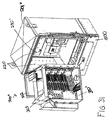
図2〜7を参照して、本願に開示した発明によるファイバ分配ハブ(FDH)の実施形態を示す。FDH200は、内部部品を収納するキャビネット201を含む。キャビネット201は開口部を有し、その開口部を通してフィーダ・ケーブル(例えば、F1ケーブル)700および加入者ケーブル708が、キャビネット201(図2Cを参照)に出入りする。スイング・フレーム300は、キャビネット201の内部に、回動自在にヒンジ355において取り付けられる。スイング・フレーム300は、スイング・フレーム300を前部分302(図4を参照)と後部分304(図2Cを参照)とに分ける隔壁301を含む。隔壁301は、終端領域311およびストレッジ領域313を有するメイン・パネル310を含む。一般に、少なくとも1つの終端モジュール400(図12Aおよび図12Bを参照)は終端領域311において提供され、少なくとも1つのストレッジ・モジュール600(図9を参照)は、ストレッジ領域313において提供される。いくつかの実施形態では、隔壁301は、メイン・パネル310に隣接して配置された第2のパネル315をも含み、ケーブル管理のために構成される。1つ以上のフィーダ・ケーブル・インタフェース800は、スイング・フレーム300の後部分に配置することができる。1つ以上のスプリッタ・モジュール500を収納する少なくとも1つのスプリッタ・モジュール・ハウジング322は、スイング・フレーム300の上に配置される。
2-7, an embodiment of a fiber distribution hub (FDH) according to the invention disclosed herein is shown. The
図3は、FDH200のケーブル配線案の例を示す概略図である。FDH200は、屋外プラント(OSP)環境において、入力ファイバと出力ファイバとの間の終端パネルにおける接続を一般に管理する。本願明細書においては、「接続」の用語は、ファイバ間の直接的および間接的な接続を含む意味で使われる。入力ファイバの例は、キャビネットに入るフィーダ・ケーブル・ファイバと、フィーダ・ケーブル・ファイバを終端パネルに結ぶ中間ファイバ(例えば、スプリッタから伸びるコネクタ化ピグテール、補修用ファイバないしジャンバー線など)とを含む。出力ファイバの例は、キャビネットを出る加入者ケーブル・ファイバと、加入者ケーブル・ファイバを終端パネルに接続するいかなる中間のファイバも含む。FDH200は、運用アクセスおよび再構成が望ましいネットワークにおける箇所において、光伝送信号のための相互接続インターフェースを提供する。例えば、上に述べたように、FDH200は、フィーダ・ケーブルを分割するために用いることができ、加入者位置に経路を設定された分配ケーブルに、スプリット・フィーダ・ケーブルを終端できる。加えて、FDH200は、収納できるサイズおよびファイバ数に幅があり、ピグテール、ファンアウト、スプリッタの工場インストールをサポートするように設計されている。
FIG. 3 is a schematic diagram illustrating an example of a cable wiring plan of the
図3に示すように、フィーダ・ケーブル700は、最初にキャビネット201(例えば、典型的には、図2Cで示すようにキャビネット201の背面または底面)を通してFDH200に配線される。ある実施形態においては、フィーダ・ケーブル700のファイバは、リボン・ファイバを含むことができる。フィーダ・ケーブル700のある例では、サービス・プロバイダの中央オフィス101に接続された12本ないし48本の個々のファイバを含む。いくつかの実施形態では、キャビネット201に入った後に、フィーダ・ケーブル700のファイバは、フィーダ・ケーブル・インタフェース800(例えば、光ファイバ・アダプタ・モジュール、スプライス・トレイ等)に配線される。フィーダ・ケーブル・インタフェース800において、1つ以上のフィーダ・ケーブル700が、別々のスプリッタ入力ファイバ702に、個別に接続している。スプリッタ入力ファイバ702は、フィーダ・ケーブル・インタフェース800から、スプリッタ・モジュール・ハウジング322まで配線される。スプリッタ・モジュール・ハウジング322において、スプリッタ入力ファイバ702は、別々のスプリッタ・モジュール500に接続している。入力ファイバ702は、それぞれ、多数のピグテール704へ別れ、各々のピグテールが、コネクタ化端部706を有する。しかしながら、他の実施形態においては、フィーダ・ケーブル700のファイバは、コネクタ化することができて、それによって、中間フィーダ・ケーブル・インタフェース800の必要を回避または除去して、スプリッタ・モジュール500に直接に配線することが可能である。
As shown in FIG. 3,
ピグテール704が稼動中でないときには、コネクタ化された端部706は、スイング・フレーム300のストレッジ領域313に取り付けられたストレッジ・モジュール600に一時的に格納することができる。ピグテール704のサービスが必要であるときには、ピグテール704は、スプリッタ・モジュール500から、スイング・フレームの終端領域311で提供される終端モジュール400に接続される。終端モジュール400において、ピグテール704が分配ケーブル708のファイバに配線される。終端パネルは、入力ファイバと出力ファイバとの境界線である。典型的分配ケーブル708は、ネットワーク(図1を参照)のF2部分を形成し、典型的には、FDH200から加入者位置709まで配線する複数のファイバ(例えば144本、216本または432本のファイバ)を含む。
When the pigtail 704 is not in operation, the
いくつかの実施形態では、フィーダ・ケーブル700のファイバの1つ以上は、スプリッタ・モジュール500のいずれにも接続されていない。むしろ、フィーダ・ケーブル700のこれらのファイバは、コネクタ化した端部714を有するパススルー・ファイバ712に接続している。スプリッタ・モジュール500に最初に接続せずに、パススルー・ファイバ712は、終端モジュール400に接続している。ファイバ712を分割することを控えることによって、より強い信号が、加入者の1人に送られるようにすることが可能である。パススルー・ファイバ712のコネクタ化された端部714は、使用されないときにはストレッジ領域313に格納することができる。
In some embodiments, one or more of the fibers of the
図2A−2Cを再度参照する。FDH200のキャビネット201は、上部パネル202、底部パネル203、右側面パネル204、左側面パネル206、背面パネル205および少なくとも1つの前部ドアを含む。いくつかの実施形態では、少なくとも1つの前部ドアは、右側ドア210および左側ドア212を含む。ある実施形態において、前部ドア210、212はロック211を含む。少なくとも1つの前部ドアはヒンジ214を用いているキャビネット201に回動自在に搭載され、キャビネット201の内部に取り付けられる部品へのアクセスを容易にする。
Reference is again made to FIGS. 2A-2C. The
一般に、FDH200のキャビネット201は、風雨、埃、ネズミなどげっ歯類や、ほかの汚染物質から内部の部品を保護するように構成される。しかしながら、キャビネット201は、据付容易のために比較的軽量で、装置内の水分の蓄積を防止するために空気が通るようになっている。いくつかの実施形態では、ヘビーパウダーのコーティング仕上げをしたアルミニウム構造もまた腐食耐性を与える。1つの実施形態においては、キャビネット201はヘビーゲージ・アルミニウムから製造されて、NEMA−4Xレートである。しかしながら、他の実施形態においては、他の材料も用いることが可能である。
In general, the
実施形態に従った、FDH200が、ポール・マウントまたは台マウント構成で、提供される。例えば、図2に示すように、キャビネット201を所望の場所に配備するのを容易にするために、ループ218をキャビネット201につけることができる。ループ218を、クレーンを使用しているキャビネットを配置するために用いることができる。特に、クレーンは地下の場所までキャビネット201を降ろすことができる。いくつかの実施形態では、ループ218は着脱可能であるか、または、表面のキャビネット・パネル202から、突き出ないように調整できる。
According to embodiments, an
また図2B−2Cに示すように、FDH200のスイング・フレーム300は、上部パネル320(底部パネル330)右側面パネル340、および左側341を含む。ヒンジ取付片350は、スイング・フレーム300の左側341に置かれる。図4で表されるように、隔壁301は、メイン・パネル310をヒンジ取付片350に接続する接続パネル319を更に含む。図4に最もよく示されているように、第2のパネル315の部分325は、スイング・フレーム300の上部パネル320を通って上方へ伸びている。隔壁301は上部および底部パネル320、330の間で垂直に広がり、右側面パネル340および左側341との間で横に広がっている。
2B-2C, the
いくつかの実施形態では、スイング・フレーム300のヒンジ取付片350は、1つ以上のヒンジ355を使用している、FDH200のキャビネット201に取り付けられる。ヒンジ355は、終端モジュール400、ストレッジ・モジュール600、フィーダ・ケーブル・インタフェース装置800およびスプリッタ・モジュール500を含めて、スイング・フレーム300の全部がキャビネット201の前部ドア210、212からスイングして出ることを可能にし、清掃、テスト、保守、追加などのためのスイング・フレーム300の後部分304にある光学部品へのアクセスを可能とする。キャビネット201からスイング・フレーム300を軸回転させて出すことは、スイング・フレーム300の右側面パネル340をキャビネット201の内部から引き出すことになる。いくつかの実施形態において、スイング・フレーム300は、キャビネット201からの90度以上軸回転できる。
In some embodiments, the
いくつかの実施形態では、スイング・フレーム300のヒンジ355は、スイング・フレーム300に配線されるファイバ・ケーブルが屈曲する単一の点を与えるために配置される。このヒンジ点は、ファイバの屈曲をコントロールするために設けられる。特に、ヒンジ355およびケーブル管理装置は、スイング・フレーム300が開閉されるときに、製造上推奨される屈曲半径が維持されることを確実にするように設計されている。ケーブル管理装置については後で詳細に述べる。1つの実施形態において、キャビネット201は、ヒンジ355付近のケーブル束にカバーをするために、工場またはプラントで組み立てることができる。キャビネット201を予め組み立てておくことは、配線が誤ってされるという可能性を減らすことができる。
In some embodiments, the
スイング・フレーム300が開いた位置にあるとき、図2Cに示すように、スイング・フレーム300の後部分304の部品にアクセスすることができる。例えば、メイン・パネル310の後ろ側および第2のパネル315の後ろ側へのアクセスが容易である。加えて、スイング・フレーム300がキャビネット201からスイングして出たときに、スプリッタ・モジュール・ハウジング322(図4を参照)にあるスプリッタ・モジュール500は、スイング・フレーム300の上部開口を通してアクセスすることができる。対照的に、スイング・フレーム300が閉じた位置(図2Bを参照)にあるときには、スイング・フレーム300の前部分302にある部品のみが容易にアクセスできる状態である。
When the
例示した実施形態において、スイング・フレーム300は、FDH200のキャビネット201内で、スイング・フレーム300を閉鎖位置にロックする解放ラッチ(図示せず)を含む。ラッチが作動すると、スイング・フレーム300は、キャビネット201から軸回転して出ることができる。加えて、軸回転するロッキング部材(図示せず)は、スイング・フレーム300を開いた位置に保つために、スイング・フレーム300の後ろ側304に取り付けることが可能である。
In the illustrated embodiment, the
図4〜5を参照する。スイング・フレーム300のストレッジ領域313は、終端領域311の下に位置する。しかしながら、他の実施形態においては、ストレッジ領域313が、終端領域311より上にまたは隣接することができる。一般に、終端領域311は終端モジュール400からのアダプタ450(図13A、図13B参照)が伸びる少なくとも1つの矩形開口部312を規定する。終端モジュール400は、本願明細書において、更に詳細に記載されている。図4に図示した実施形態において、終端領域311は、開口部312の2つの列を含み、各列は、12の長形スロットを含んでいる。ストリップ片309は、各列の開口部312を切り離しており、表面に粘着ラベルで、コネクタ指定等の情報を表示できる。ストレッジ領域313も、ストレッジ・モジュール600(図9を参照)が取り付けられる1つ以上の開口部314を規定する。ストレッジ・モジュール600は、本願明細書において、更に詳細に記載されている。
Reference is made to FIGS. The
隔壁301は、底部パネル330を前部分331(図4を参照)と後部分336(図2Cおよび14を参照)との2つに分ける。一般に、底部パネル330の前部分331は、隔壁301から前方へ突出する。いくつかの実施形態では、前部分331は更に第1の前部分332および第2の前部分334に分けられる。各前部分332、334は、それぞれ、フランジ333、335を含み、底部パネル330から実質的に垂直に突き出ている。底部パネル330の前部分331は、それによって、ストレッジ領域313から、または第2のパネル315から、ゆるんだ、あるいは、余分なファイバを保持するように構成されるトラフを形成する。第1の前部分332のエッジ337は、スイング・フレーム300がトラフと干渉することなく、軸回転して開くことができるように、角度がついている。
図4、図6に最もよく示されているように、隔壁は、側面パネル340を前部フランジ342と後部フランジ344のそれぞれに分ける。前部フランジ342は第2のパネル315から前方へ伸び、後部フランジ344は第2のパネル315から後方に伸びる。後部フランジ344は、底部パネル330から、上部パネル320から伸びている屈曲リミッタ962まで伸びる。前部フランジ342は、第2のパネル315の突き出ている部分325に、上部パネル320を過ぎて底部パネル330から伸びる。いくつかの実施形態では、前部フランジ342は、後部フランジ344に実質的に平行な前方の部分344と、第2のパネル315の突き出ている部分325と前方の部分344の間で伸びる曲げられた部分343と、を含む。
As best shown in FIGS. 4 and 6, the septum separates the
図7に最もよく示されているように、スイング・フレーム300の上部パネル320は実質的に矩形である。上部パネル320は、前部エッジ326、後部エッジ327を含む。フランジ323、324(図4を参照)は、それぞれ、エッジ326、327から上方へ突き出る。上部パネル320も、側面341に隣接した第1端部328と、側面パネル340に隣接する第2の、反対側の端部とを有する。屈曲半径リミッタ940は、第1端部328から上方へ伸びる。いくつかの実施形態では、上部パネル320の端部329の一部分が、側面パネル340の前部フランジ342を有するチャネルBの幅を規定する。チャネルBを規定する端部329の部分は、チャネルBのところで終わっている。チャネルBの深さは、第2のパネル315から底部パネル330の第2の前部分33のフランジ335まで伸びる。FDH200のスプリッタ・モジュール・ハウジング322は、第1端部328に隣接して上部パネル320上に配置される。スプリッタ・モジュール・ハウジング322は、FDH200のスプリッタ・モジュール500を保護して、組織化して、固定するのに役立つ。
As best shown in FIG. 7, the
スプリッタ・モジュール・ハウジング322は、スプリッタ・モジュール500の数がいろいろであっても収納するように、さまざまなサイズのものを設けることができる。スプリッタ・モジュール・ハウジング322は、一般に矩形であり、1つ以上の光スプリッタ・モジュール500を収納するような大きさの開放空間内に、1つ以上の収納場所を規定する。スプリッタ・モジュール500を収納するために、スプリッタ・モジュール・ハウジング322は、スプリッタ・モジュール500を支持し固定するような構造を持っている。実施形態において、スプリッタ・モジュール500は、スプリッタ・モジュール・ハウジング322にはめ込むように設計されている。ある実施形態において、スプリッタ・モジュール500は、スプリッタ・モジュール・ハウジング322に、前部から後部へと入れられる(すなわち、側面329から、側面328の方向に)。モジュール・ハウジング322は更に、スプリッタ・モジュール500が、例えば図3のファイバ702のように、スプリッタ・モジュール500の1つを端部上で入力ファイバを受け入れ、スプリッタ500の対向する端部から、例えば図3のピグテール704のように、多数のファイバを出力することを可能にするように構成される。
The
図8A−8Cを、ここで参照する。スプリッタ・モジュール・ハウジング322に取り付けることが可能である1つのタイプのスプリッタ・モジュール500は、一体型コネクタを有するスプリッタである。図8Aは、この種のスプリッタ・モジュール500の左側面図である。スプリッタ・モジュール500は、前方に突き出ている少なくとも1つの保護ブーツ510および後方に突き出ている少なくとも1つの一体型コネクタ520を有するハウジング505を含む。図示した実施形態において、2つのブーツ510は、前部から突き出て、2つの一体型コネクタ520は後方にスプリッタハウジング505から突き出ている。1つの実施形態(図示せず)において、各スプリッタは、4つの一体型コネクタ520を備えている。いくつかの実施形態では、ハンドル540もスプリッタハウジング505の前端部から突き出る。図8Bは、スプリッタ・モジュール500の内部部品を示している図8Aのスプリッタ・モジュール500の分解図である。
Reference is now made to FIGS. 8A-8C. One type of
図8Cは、スプリッタ・モジュール・ハウジング322に嵌入される図7Aのスプリッタ・モジュール500の横断面を示す。アダプタ・アセンブリ530は、ファスナー536を使用してスプリッタ・モジュール・ハウジング322に固定する。実施形態において、アダプタ・アセンブリ530は、スプリッタ・モジュール・ハウジング322の後方に搭載される。スプリッタ・モジュール500がスプリッタ・モジュール・ハウジング322に挿入されるときに、アダプタ・アセンブリ530はスプリッタ・モジュール500のコネクタ520を受け入れるように構成される。上に示すように、アダプタ・アセンブリ530は、更にフィーダ・ケーブル700と関連する対向するコネクタを受け入れるように構成される。いくつかの実施形態では、アダプタ・アセンブリ530は、スプリッタ入力ファイバ702を終端しているコネクタ703を受け入れる。他の実施形態では、アダプタ・アセンブリ530は、フィーダ・ケーブル700を終端しているコネクタ701を受け入れる。このようにして、フィーダ・ケーブル・ファイバ700は、容易に、スプリッタ・モジュール500に連結できる。
FIG. 8C shows a cross section of the
他の実施形態では、スプリッタ・モジュール500は、一体型コネクタ520を含まない。このような実施形態では、アダプタ・アセンブリ530は、スプリッタ・モジュール・ハウジング322に搭載されず、フィーダ・ケーブル700は直接スプリッタ・モジュール500に差し込むことができない。むしろ、入力ピグテール(図示せず)が、スプリッタハウジング505を通って、スプリッタ・モジュール500に入る。入力ピグテールの対向する端部は、コネクタ化していても良いし、していなくても良い。端部701がコネクタ(図示せず)に終端する場合には、入力ファイバ702は、アダプタ・モジュール810(図18を参照)を使用しているフィーダ・ケーブル700とインターフェースする。端部701がコネクタ化していない場合には、入力ファイバ702は、スプライス・トレイ808(図19を参照)を使用して、フィーダ・ケーブル700をケーブルでつなぎ合わせる。
In other embodiments, the
典型的には、各スプリッタ・モジュール500は、1から4の入力ファイバを受け入れ、各入力ファイバに対して、2から16のファイバ704を出力する。1つの実施形態において、4つの入力ファイバ702が、スプリッタ・モジュール500に入り、32のピグテールファイバ704がスプリッタ・モジュール500を出る。スプリッタ・モジュール500についてのさらなる情報は、2006年2月13日に出願され、「光ファイバ・スプリッタ・モジュール(Fiber Optic Splitter Module)」と題された、米国特許出願第11/354,297号から得られる。この出願は、引用により本明細書に組み込まれる。他のタイプのスプリッタ・モジュールについての追加的情報は、2004年11月3日に出願された、「後部コネクタを備える光ファイバモジュールおよびシステム(Fiber Optic Module And System Including Rear Connectors)」と題する米国特許出願第10/980,978号、2005年8月29日に出願された「コネクタアクセスを有する光ファイバ・スプリッタ・モジュール(Fiber Optic Splitter Module)」と題する米国出願第11/138063号、2005年5月25日に出願された、「光ファイバ・スプリッタ・モジュール(Fiber Optic Splitter Module With Connector Access)」と題する、米国特許出願第11/215837号、2005年12月に出願され、「ファイバ分配ハブのためのスプリッタ・モジュール(Splitter Modules For Fiber Distribution Hubs)」と題された、米国特許出願第11/321696号、から得られる。これらの開示内容は、引用により本願明細書に組み入れられる。
Typically, each
図9〜10を、ここで参照する。スプリッタ・モジュール500およびストレッジ・モジュール600は、逐次、スイング・フレーム300に追加することが可能である。図9は、スプリッタ・モジュール500が、スプリッタ・モジュール500上の保護ブーツ510から出ている多数のコネクタ化されたピグテール704を有することを図示する。コネクタ化されたピグテール704が、典型的には、スイング・フレーム300に取付けられる前に、1つ以上のストレッジ・モジュール600に格納される。いくつかの実施形態では、スプリッタ・モジュール500が出荷される前に、各ピグテール704のコネクタ706は、ストレッジ・モジュール600に固定される。典型的には、各スプリッタ・モジュール500のコネクタ化されたピグテール704は、それぞれ8つのコネクタ持つ4つのストレッジ・モジュール600に配線される。
Reference is now made to FIGS. The
ストレッジ・モジュール600は、前側602および後ろ側604を有する本体610を含む。本体610は、少なくとも1つのファイバ・コネクタ706を持つように構成される。典型的には、本体610は、約8つのコネクタ706を持つように構成される。いくつかの実施形態では、本体610は、単一の列構成のファイバ・コネクタ706を保持するように配置される。他の実施形態では、本体610は、コネクタ706を、正方形のパターンのまたは他の所望の構成で持つようにすることができる。ストレッジ・モジュール600についてのさらなる情報は、2003年6月30日に出願された、「光ファイバ・コネクタ・ホルダおよび方式(Fiber Optic Connector Holder and Method)」と題する、米国特許出願第10/610,325号、2003年7月2日に出願された、「テレコミュニケーション・コネクタ・キャビネット(Telecommunications Connection Cabinet)」と題する米国特許出願第10/613,764号、および、2004年1月18に出願された、「多重位置光ファイバ・コネクタ・ホルダとその方式(Multi-position Fiber Optic Connector Holder and Method)」と題する、米国特許出願第10/871,555号、から得られる。これらの出願は、引用により本明細書に組み込まれる。
いくつかの実施形態では、本体610は、メイン・パネル310のストレッジ領域313において規定された開口部314のうちの1つにはめ込まれるように設計される。開口部314は、メイン・パネル310のストレッジ領域313の中で、所望の構成に配列することができる。図10に示される実施形態において、メイン・パネル310のストレッジ領域313は、矩形のパターンの9つの開口部314を規定する。各開口部314は、列になった8つのファイバ・コネクタ706を保持するために配置されたストレッジ・モジュール本体610を受け入れるように構成される。
In some embodiments, the body 610 is designed to fit into one of the
図10に示すように、スプリッタ・モジュール500が取付けに際してスプリッタ・モジュール・ハウジング322に入れられるときに、対応するストレッジ・モジュール600が、メイン・パネル310のストレッジ領域313に入れられる。分かりやすさのため、1つのピグテール704および1つのストレッジ・モジュール600を有するスプリッタを1つだけ図示した。スプリッタ・モジュール500からストレッジ・モジュール600へ伸びるピグテール704は、保護ブーツ510から、上部パネル320を横切り、第2のパネル315の前側のチャネルBを通って下方に向かい、スイング・フレーム300の底部パネル330を横切って配線される。
As shown in FIG. 10, when the
この配線を達成するために、上部パネル320および第2パネル315は、ケーブル管理装置を備える。いくつかの実施形態では、上部パネル320上のケーブル管理装置は、スプリッタハウジング322および屈曲半径リミッタ962の間に位置する第1のスプール952と、屈曲リミッタ940および前部フランジ342の間に位置する第2のスプール954とを含む。スプリッタ500から出力されるピグテール704は、最初に第1のスプール952周りで、次に第2のスプール954周りで巻きつけられる。
In order to achieve this wiring, the
タブ965を有していて、上部パネル320から下方へ伸びている屈曲半径リミッタ964は、部分的にチャネルBを規定する。第2のスプール954から、ピグテール704のいくつかは、屈曲リミッタに配線され、チャンネルBに入るいくつかの実施形態では、部分的なファイバ・スプール966は、第2のパネル315の突き出ている部分325から伸びるように取り付けられ、ファイバをチャンネルBに入れるように配線の方向をつける。過剰な重量やファイバ704のもつれを避けるために、ファイバ704のいくつかは、屈曲リミッタ964の代わりに、部分的なスプール966の上を通してチャネルBの中に配線できる。余分なたるみは、また、屈曲リミッタ964の代わりにスプール966の上を通してピグテール704を配線することにより取ることができる。屈曲リミッタ968は、また、第2のパネル315の突き出ている部分325に搭載され、ファイバを部分的なスプール966まで配線するように方向付ける。
A bend radius limiter 964 having a
第2のパネル315の前部は、部分的なスプール970の少なくとも1つの列および半径リミッタ980の少なくとも1つの列を含む。1つの実施形態において、部分的なスプール970は、チャネルBを下に配線されるファイバを、スプール970のうち1つの周りに少なくとも部分的に巻きつけることを可能にするような方向に置かれる。ファイバは、部分的なスプール970から、底部パネル330に沿ってストレッジ・モジュール600へ、あるいは、リミッタ980を越えて、終端モジュール400へと、進むことができる。リミッタ980は、部分的なスプール970から配線されるファイバが、過剰に曲げられることなく、終端モジュール400に進むことを可能にするような方向に置かれる。
The front of the
図11を、ここで参照する。ストレッジ・モジュール600に保持されるピグテール704は、加入者分配線708に接続しなければならないときに、対応するコネクタ706はストレッジ・モジュール600から取り外されて、終端モジュール400上の適当なアダプタ450へ移される。この移す過程の間、ファイバは、アダプタ450に達するために、部分的なスプール972のような、別の部分的なスプール970周辺で巻き直すことが必要となる可能性がある。部分的なスプール972から、ファイバはアダプタ450に達する前に過剰な曲げを避けるために適切なリミッタ980周辺に送られることが可能である。いくつかの実施形態では、ファイバはまた、アダプタ450に差し込む前に、メイン・パネル310の終端セクション311から伸びている支持フィンガ990を通している。当初、ストレッジ・モジュール600に固定されたファイバ704の全てが加入者終端モジュール400に配線されたときには、空のストレッジ・モジュール600を、新規なスプリッタ・モジュール500および新規なストレッジ・モジュール600のための余裕をつくるために、取り除くことができる。
Reference is now made to FIG. When the pigtail 704 held in the
図12A−12Bを、ここで参照する。時間経過と、加入者の数の増加とともに、ユーザは終端モジュール400をスイング・フレーム300に追加することができる。図12Bおよび図12Aは、終端モジュール400の1つの実施形態を示す。終端モジュール400は、実質的にL字型構成に配置された終端レッグ410およびマネジメント・レッグ420を含む。いくつかの実施形態では、連結セクション430は、終端レッグ410をマネジメント・レッグ420に接続する。他の実施形態では、連結セクション430はよりモノリシックにシターンが形成されている終端レッグ410またはマネジメント・レッグ420。さらに他の実施形態においては、終端レッグ410、マネジメント・レッグ420および連結セクション430は、一体に形成される(例えば、曲がったシートメタルの単一の部品として構成される)。
Reference is now made to FIGS. 12A-12B. As time progresses and the number of subscribers increases, the user can add
いくつかの実施形態では、終端モジュール400(図12Bに示す)の終端レッグ410の前側は、メイン・パネル310の後ろ側に取付けられる。1つの実施形態において、終端レッグ410はネジ417を使用しているメイン・パネル310に取付けられる。しかしながら、他の実施形態においては、ボルト、鋲、釘、その他のデバイスのようなファスナーを、モジュール400をメイン・パネル310に接続するために用いることができる。さらに他の実施形態において、モジュール400は、接着剤を使用してメイン・パネル310に取り付けられることが可能である。
In some embodiments, the front side of the
各終端モジュール400は、主ケーブル700のファイバを、分配ケーブル708のファイバに接続するための光ファイバ・アダプタ450の少なくとも1つの列を含む。各アダプタ450は、前端部452および後端部454を有する。各アダプタ450の前端部452は、本線700とインターフェースするファイバ712のコネクタ714、または、本線700から分れたファイバ704のコネクタ706を保持するように構成される。各アダプタ450の後端部454は、分配ケーブル708のファイバのコネクタ710を保持するように構成される。コネクタ706がメイン・パネル310の前側から、アダプタ450の前端部452に入り、分配ケーブル708のコネクタ710が、メイン・パネル310の後ろ側からアダプタ450に入るように、アダプタ450は終端レッグ410から突き出ている。
Each
上述の実施形態において、各モジュール400は、2本の並んだバンクを協調して規定するアダプタ450の6つの水平な列を含む。モジュール400がメイン・パネル310に搭載されるときに、レッグ410の前側は、メイン・パネル310の後側に接し、アダプタ450の列は、パネル310により規定された対応する水平スロット314を通って、前方へ突き出る。
In the embodiment described above, each
マネジメント・レッグ420は、終端レッグ410から後方に伸びている。各マネジメント・レッグ420は、モジュール400上の多数のアダプタ450を収容する適当数のファンアウト424を含む。例えば、ある実施形態においては、モジュール400の終端レッグ410は、各列が12のアダプタ450を有する6列のアダプタ450を含み、マネジメント・レッグ420は12:1のファンアウト424を6つ有する。本願明細書において使用する用語として、「12:1のファンアウト」とは、12の光ファイバを受けて、12のファイバを含んでいる単一のケーブル・リボンを出力するように構成されるファンアウトである。他の実施形態では、12:1のファンアウトの代わりに、9つの8:1のファンアウト、あるいは、3つの24:1のファンアウトが用いられる。さらに他の実施形態において、ファンアウトがファイバをアップジャケット(upjacket)するのに使うことができる。
いくつかの実施形態では、終端モジュール400は、各々のアダプタ450に連結するコネクタ化分配ファイバ708を含むように、出荷前に配線済みとなっている。塵キャップ453は、終端した分配ファイバ708を、塵、ほこりおよび他の汚染物から保護するためにアダプタ450の前端部452に、一般に提供される。各分配ファイバ708のコネクタ710は、アダプタ450の後端部454内に搭載され、配布ファイバ708が、コネクタ710から終端モジュール400のマネジメント・レッグ420に提供されたファンアウト424まで配線される。さらに他の実施形態において、終端モジュール400は事前に配線が行われず、塵キャップ455はまた、アダプタ450を保護するためにアダプタ450の後端部454に提供される。
In some embodiments, the
いくつかの実施形態では、終端モジュール400のマネジメント・レッグ420も、分配ファイバ708の余分なファイバの長さを管理する少なくとも1つのケーブル管理装置425を含む。通常、この種のシステムでは、ファイバ708はケーブル管理装置425に最初に配線され、それからファンアウト424に配線される。ケーブル管理装置425の例は、ファイバ・スプール、1つ以上の半径屈曲リミッタ、1つ以上のファイバ・クリップ、および、その他この種の装置を含む。ここに示した例では、マネジメント・レッグ420は、2つの半径屈曲リミッタから形成されるファイバ・スプール426を含む。各半径屈曲リミッタは、スプール426上のファイバを保持するためのフランジ427を含む。いくつかの実施形態では、ファイバ・ケーブルを保持するための1つ以上のファイバ・ケーブル・クリップ428を、スプール426の半径屈曲リミッタの間に置くことができる。
In some embodiments, the
図13を、ここで参照する。終端モジュール400のマネジメント・レッグ420は、ケーブル管理装置425からファンアウト424まで配線したファイバが通過する開口部422を含む。ファンアウト424を出ると、リボン・ファイバが、キャビネット・ファンアウト(図示せず)または他のケーブル・インターフェイス装置に配線される。他の実施形態では、ファンアウト424は、ケーブル管理装置425と同じマネジメント・レッグ420の側に提供される。このような実施形態では、リボン・ファイバは、ファンアウト424から、開口部422を通って、キャビネット・ファンアウトに配線される。キャビネット・ファンアウトは、キャビネット201の内部に取り付けられて、スイング・フレーム300に取り付けられない。キャビネット・ファンアウトは、FDH200を出る単一の被覆されたスタブ・ケーブルに入るリボン・ファイバを減らすために用いることができる。スタブ・ケーブルは、FDH200の外の加入者分配ケーブルにつなぎ合わされる。種々の実施形態において、スタブ・ケーブルは、約25フィートから約300フィートまでいろいろな長さである。他の実施形態では、分配ケーブル708は、キャビネット201の中に配線し、ファイバ708につなぎ合わせるか、さもなければ、接続することができる。
Reference is now made to FIG. The
図14を、ここで参照する。スイング・フレーム300の後ろ側304は、少なくとも1つの終端モジュール400を収納するのに適している開放チャンバを形成する。開放チャンバは、隔壁301、上部パネル320、底部パネル330および側面パネル340により規定される。図14は、開放チャンバに搭載された4つの終端モジュール400の後ろからの斜視図である。アダプタ450は、見易さのために取り除かれている。他の実施形態では、所望の数だけ、終端モジュール400を、スイング・フレーム300に搭載できる。終端モジュール400は、メイン・パネル310の終端領域311の後ろ側に取付けられるように構成される。
Reference is now made to FIG. The
図15は、その中で搭載された4つの終端モジュール400を有するスイング・フレーム300の左側面図を示す。多数の終端モジュール400がメイン・パネル310の後ろ側に搭載される場合には、終端モジュール400のマネジメント・レッグ420は、側面パネル340の反対の部分的な側面パネルを形成する。いくつかの実施形態では、モジュール400のマネジメント・レッグ420は、互いに、またはスイング・フレーム300に固定される。他の実施形態では、図15に示されているように、モジュール400は、終端レッグ410のみで、スイング・フレーム300に固定され、マネジメント・レッグ420は、自由なフローティングである。
FIG. 15 shows a left side view of a
図16〜19を、ここで参照する。スイング・フレーム300は、入力フィーダ・ケーブル700および分配線708の間に、多数のファイバ経路をつくるために、異なるインターフェース装置800(図3を参照)およびケーブル管理装置で構成できる。インターフェース装置800および特定の構成において使用する管理装置は、フィーダ・ケーブル700を分割することが望ましいかどうか、そして、スプリッタ・モジュール500のどんなタイプが利用されるかに依存する。
Reference is now made to FIGS. The
いくつかの実施形態では、フィーダ・ケーブル700は、1つ以上のスプリッタ入力ファイバ702に接続する。そのような実施形態において、スプリッタ入力ファイバ702の第1端部701は、コネクタ化される。別の実施形態においては、第1端部701はコネクタ化されていない。入力ファイバ702の対向端部703は、図8A−8Cに表されるスプリッタ・モジュールを使用するようなときに、スプリッタ・モジュール500上の一体型コネクタ520とインターフェースすることができ、あるいは、スプリッタハウジング505を貫通できる。しかしながら、他の実施形態においては、フィーダ・ケーブル700は、スプリッタ・モジュール500の一体型コネクタ520とインターフェースするように構成されたコネクタを備えている。
In some embodiments, the
図16は、コネクタ化されたフィーダ・ケーブル700とスプリッタ・モジュール500をインターフェースするのに適しているスイング・フレーム300の背面図である。このインターフェースを達成するために、ケーブル管理装置は、構成C1により設けられる。構成C1では、ケーブルストレッジ・スプール922および1つ以上の部分的なストレッジ・スプール924が、スイング・フレーム300の側面パネル340に取付けられる。ファンアウト装置926は、スプール922、924に隣接して設置される。半径リミッタ936は、上部パネル320および側面パネル340により形成される隅の近くで、第2のパネルに取り付けられる。上部パネル320から下方へ突出している支持フィンガ932は、ファイバが上部パネル320の一端部329から、他端部328まで沿って配線されることが可能であるような経路Aを形成する。いくつかの実施形態では、支持フィンガ932は、少なくとも2本のフィンガ932を有する多分岐したクリップ934を含む。各フィンガ932は、異なる方向に伸びている。1つの例示の実施形態において、多分岐したクリップ934は、互いに直交して配置された4本のフィンガ932を含む。余分なファイバの長さは、ピグテール702を多分岐したクリップ934に巻くことにより、取ることができる。タブ945を有するリミッタ940は、上部パネルから伸びる。
FIG. 16 is a rear view of a
フィーダ・ケーブル700をスプリッタ500に接続するために、ケーブル700は、最初に、スプール922、924周辺に、次に、ファンアウト装置926に配線される。ファンアウト装置926は、フィーダ・ケーブル700のファイバを、個々の入力ファイバに分離する。フィーダ・ケーブル700の個々のファイバの余分な長さは、スプール922、924周りにファイバを巻きつけることにより格納できる。フィーダ・ケーブル700のファイバは、次に、上部パネル320から下方に突出している支持フィンガ932を使用してリミッタ936周辺に、経路Aに沿って配線される。フィーダ・ケーブル700は、次に、上部パネル320から伸びているリミッタ940周辺でカーブして、直接スプリッタ・モジュール・ハウジング322に固定されているアダプタ・アセンブリ530のうちの少なくとも1つに接続される。フィーダ・ケーブル700のファイバは、ゆるいバッファチューブによって、スイング・フレーム300の中で配線され、保護することができる。
In order to connect the
図17は、スプリッタ・モジュール500にコネクタ化されたフィーダ・ケーブル700とインターフェースするのに適しているスイング・フレーム300の後ろからの斜視図である。ケーブル管理装置は、構成C1のバリエーションにしたがって、設けられる。ストレッジ・スプール922、924およびファンアウト装置926は、側面パネル340よりむしろ第2のパネル315の後ろ側に取付けられる。他の実施形態(図示せず)において、ストレッジ・スプール922、924およびファンアウト装置926は、底部パネル330に搭載することができる。スプール922、924およびファンアウト装置926の位置には関係なく、フィーダ・ケーブル700は、ファンアウト装置926から屈曲リミッタ936まで、経路Aに沿って、屈曲リミッタ940を越えて配線され、さらに、スプリッタ・モジュール・ハウジング322に搭載されたアダプタ・アセンブリ530まで配線される。
FIG. 17 is a perspective view from the back of a
図18〜19を、ここで参照する。フィーダ・ケーブル700は、直接スプリッタ500に接続するのではなく、むしろ、少なくとも1つのインターフェース装置800を使用して、スプリッタ入力702とインターフェースすることが可能である。図18は、スプリッタ・モジュール500を有するコネクタ化されたフィーダ・ケーブル700と、中間スプリッタ入力ファイバ702を通して、インターフェースするように構成されるスイング・フレーム300の後ろからの斜視図である。各スプリッタ入力ファイバ702は、スプリッタ500の一体型コネクタ520の反対側のアダプタ・アセンブリ530の1つに差し込む第1のコネクタ化端部703を有する。しかしながら、一体型コネクタを有するスプリッタを使用していない他の実施形態において、スプリッタ入力702は、アダプタ・アセンブリ530に差し込むのではなく、むしろ、スプリッタハウジング505を突き抜けるピグテールである。各スプリッタ入力ファイバ702は、フィーダ・ケーブル700のファイバのコネクタ化された端部とインターフェースする第2のコネクタ化した端部701を有する。
Reference is now made to FIGS. The
このような入力ピグテール702は、屈曲半径リミッタ940の上を通って、アダプタ・アセンブリ530から、図16で示す上部パネル320の下を通して配線される。特に、入力ピグテール702は、経路Aに沿って、支持フィンガ932を使用して、側面パネル340の方へ、それから半径屈曲リミッタ周辺に配線される。入力ピグテールの端部701は、次に、第1のアダプタ・モジュール820を使用しているフィーダ・ケーブル700に接続される。いくつかの実施形態では、第1のアダプタ・モジュールは、底部パネル330に隣接する第2のパネル315に取り付けられる。しかしながら、他の実施形態では、第1のアダプタ・モジュール820は、底部パネル330または側面パネル340に固定できる。第1のアダプタ・モジュール820は、1つ以上の列に配置される多数のアダプタ825を含む。いくつかの実施形態では、各列は、約6つのアダプタ825を含む。アダプタ・モジュールについての追加的情報は、米国出願2005年3月31日に出願された、「コネクタ・ストレッジを備えるアダプタ・ブロック(Adapter Block Including Connector Storage)」と題する米国出願第11/095,033号、および米国特許第5,497,444号、第5,717,810号、第5,758,003号、第6,591,051号から得られる。
Such an
フィーダ・ケーブル700を第1のアダプタ・モジュール820に接続するために、追加のケーブル管理装置が、第2の構成C2に従って提供される。第2の構成C2は、ファンアウト装置901および1つ以上の完全あるいは部分的なゆるみのストレッジ・ファイバ・スプール902、904をそれぞれ含む。上述の実施形態では、ファンアウト装置901およびストレッジ・スプール902、904は、底部パネル330に取付けられる。
In order to connect the
フィーダ・ケーブル700は、最初に、ファンアウト装置901に配線され、リボン・ケーブル700のファイバを個々のファイバに分ける。フィーダ・ケーブル700の個々のファイバの余分な長さは、ゆるみストレッジ・スプール902および部分的なゆるみストレッジ・スプール904に格納できる。フィーダ・ケーブル700のファイバは、次に、第1のアダプタ・モジュール820に配線される。フィーダ・ケーブル700のコネクタ化された端部は、第1のアダプタ・モジュール820のアダプタ825の端部に搭載される。入力ファイバ702のコネクタ化された端701は、半径リミッタ936から第1のアダプタ・モジュール820のアダプタ825の対向端部まで、配線される。アダプタ825は、フィーダ・ケーブル・ファイバ700のコネクタおよび入力ファイバ702のコネクタ701の間のインターフェースを提供する。図19は、スプリッタ・モジュールと、コネクタ化していない端部を有するフィーダ・ケーブル700の使用のために構成されたスイング・フレーム300の後ろからの斜視図である。フィーダ・ケーブル700は、コネクタ化していない第2端部701を有するスプリッタ・入力ファイバ702につなぎ合わされる。フィーダ・ケーブル700を、非接続状態のファイバ入力702に接続するために、スプライス・トレイ830をスイング・フレーム300の後ろ側304に取り付ける。
The
フィーダ・ケーブル700をスプライス・トレイ830に接続するために、追加的ケーブル管理装置が、第3構成C3にしたがって、取り付けられる。第3の構成C3は、スプライス・トレイ830周辺に取り付けられた、ファンアウト装置907および1つ以上の半径屈曲リミッタ906を含む。加えて、少なくとも1つの半径屈曲リミッタ908は、スプライス・トレイ830に隣接して配置される。各リミッタ906は、リミッタ906周辺でファイバのループを維持するタブ907を含む。リミッタ906は、ファイバがスプライス・トレイ830の隅でつかまってしまうのを防止する向きに置かれる。いくつかの実施形態では、スプライス・トレイ830およびリミッタ906は、第2のパネル315の裏側に配置される。しかしながら、他の実施形態において、スプライス・トレイ830およびリミッタ906は、スイング・フレーム300の後ろ側304の、どの所望の位置にも配置することができる。
In order to connect the
フィーダ・ケーブル700のコネクタ化されていない端部は、リミッタ906周辺を通って、スプライス・トレイ808に配線される。フィーダ・ケーブル700の個々のファイバの余分な長さは、スプライス・トレイ830周りでファイバを巻きつけることにより格納できる。スプリッタ・モジュール500からの入力ファイバ702は、半径リミッタ936から、リミッタ908周辺を通って、スプライス・トレイ830に配線される。フィーダ・ケーブル700のコネクタ化されていない端部は、入力ファイバ702のコネクタ化された端部701で、つなぎ合わされる。
The non-connector end of the
つづいて図16〜19を参照するが、いくつかの実施形態では、加入者に、より強いかより信頼性が高い信号の伝送を可能にするためにフィーダ・ケーブル700の1つ以上を分割しないほうが望ましいことがある。いくつかの実施形態では、したがって、スイング・フレーム300は、更に、少なくとも1つのファイバ(パススルー・ファイバと言う)を、フィーダ・ケーブル700からのファイバとインターフェースすることを可能にするように構成される。パススルー・ファイバ712は、スプリッタ・モジュール500をバイパスして、スイング・フレーム300の前部へ進み、分配線708とインターフェースする。
Continuing with reference to FIGS. 16-19, in some embodiments, one or more of the
このような配線を達成するために、スイング・フレーム300は、側面パネル340の後部フランジ344の開口部910を含む。いくつかの実施形態では、開口部910は、開口部910を経由するファイバの過剰な曲げを防止するために、フランジ344の外側表面上から外へ伸びている半径リミッタ912(図13に最も良く示されている)を含む。タブ915は、また、後部フランジ344の外側に押し付けられて、後部フランジ344の外側を上に向かうチャネルを規定する。半径屈曲リミッタ962は、側面パネル340の後部フランジ344を上部パネル320に連結する。追加的なケーブル管理装置は、スイング・フレーム300が組み立てられる構成C1、C2、C3に基づいて提供される。
To achieve such wiring, the
図17を参照する。スイング・フレーム300が構成C1のように配置される場合には、フィーダ・ケーブル700のコネクタ化ファイバは、第2のアダプタ・モジュール810を使用している入力ファイバ702に接続する。アダプタ・モジュール810は、どちらの端部からもコネクタ化されたファイバを受け入れるように構成された多数の光ファイバ・アダプタ815を含む。スイング・フレーム300も、屈曲半径リミッタ906およびゆるみストレッジ・スプール902、904の形で追加的なケーブル管理を含む。
Refer to FIG. When the
スプリッタ・モジュール500をバイパスするために、フィーダ・ケーブル700は、スプール922、924周りを通って、ファンアウト装置926まで配線される。しかしながら、ファンアウト装置926から、フィーダ・ケーブル・ファイバ700は、スプール922、924の後ろをまわり、屈曲リミッタ926のまわりを通って、スプール902、904の周りを配線される。スプール902、904から、ファイバ700のコネクタ化された端部は、アダプタ・モジュール810に固定される。アダプタ・モジュール810は、ファイバ700を、開口部910から出て、側面パネル340をリミッタ962まで上がり、上部パネル320まで配線されたパススルー・ファイバ712のコネクタ化された端部に接続する。上部パネル320から、パススルー・ファイバ712は、図10および11について上で述べたように、終端モジュール400の方に配線される。図18において、パススルー・ファイバ712は、また、第2の構成C2のように用いることが可能である。フィーダ・ケーブル700は、また、ファンアウト装置901に、まず配線され、それから、スプール902、904に収納されているたるみを有するアダプタ・モジュール820の一方の端部に配線される。しかしながら、アダプタ・モジュール820の他の端部につながっているスプリッタ・ピグテール702の代わりに、パススルー・ピグテール712が、アダプタ・モジュール820に差し込み接続する。パススルー・ピグテール712は、次に、前のパラグラフで述べたものと同じ配線パターンで配線される。
To bypass the
図19を参照する。パススルー・ピグテール712は、また、フィーダ・ケーブル700のコネクタ化していない端部につなぎ合わされることも可能である。この種の構成が要求される場合には、スイング・フレーム300は、図17について上に述べた第2のアダプタ・モジュール810を備える。フィーダ・ケーブル700は、また、リミッタ906周りに配線され、構成C3にしたがって、上に、スプライス・トレイ830まで配線される。フィーダ・ケーブル700の個々のファイバの余分な長さは、リミッタ906周りにファイバを巻きつけることにより格納できる。しかしながら、フィーダ・ケーブル700のファイバは、スプリッタ入力702によりむしろコネクタ化されたピグテール711につなぎ合わされる。スプライス・トレイ830から、コネクタ化されたピグテール711は、ストレッジ・スプール902、904周りを配線され、第2のアダプタ・モジュール810に差し込み接続する。第2のアダプタ・モジュール810は、開口部910から出て、側面パネル340をリミッタ962まで上がり、上部パネル320まで配線されたコネクタ化パススルー・ファイバ712でピグテール711を接続される。
Refer to FIG. The pass-through
パススルー・ファイバ712は、スプリッタ・モジュール500をバイパスし、上部パネル320の第2のファイバ・スプール954の周りを通り、リミッタ964か部分的スプール966を経てチャネルBに配線される。スイング・フレームの前側302に沿ったパススルー・ファイバ712の配線は、図10および11について上に述べたように、スプリッタ・ピグテール704の配線と実質的に同様である。典型的には、パススルー・ファイバ712は、終端モジュール400上のアダプタ450を経て加入者回線708に、直接接続している。しかしながら、いくつかの実施形態では、パススルー・ファイバ712は、ストレッジ・モジュール600上の空いた場所に収納することができる。
Pass-through
図20〜29は、図20〜23に開示した実施形態FDH200'の原理に従った特徴を有する代替のファイバ分配ハブ(FDH)を示す。ファイバ分配ハブ200'は、ファイバ分配ハブ200に関してすでに述べた、同じコンポーネントを収容しているキャビネット201'を含む。例えば、キャビネット201'は、前部ドア210、212開くことによってアクセスできる主コンパートメント230を規定する。スイング・フレーム300は、主コンパートメント230の中に回動自在に搭載される。終端領域およびストレッジ領域が、スイング・フレームに設けられる。スプリッタは、また、バネ・フレームを備える。主コンパートメント230の内部コンポーネントに関する更なる詳細は、ファイバ分配ハブ200についての詳細な説明の箇所にある。
20-29 show an alternative fiber distribution hub (FDH) having features in accordance with the principles of the
ファイバ分配ハブ200'は、キャビネット201'の後方からアクセスすることができる補助コンパートメント232を含むように修正されている。補助コンパートメント232は、また、ポケット、リセス、差込領域、チャンバ、あるいは同様な用語で参照される。補助コンパートメント232は、補助ドア234を開くことによってアクセスすることができる。補助ドア234は、キャビネット200'の外側に位置する。補助ドア234を開くと、補助コンパートメント232にアクセスすることができるが、キャビネット201'の主コンパートメント230にはアクセスできない。したがって、フィールド技術者は、迅速に、ファイバ分配ハブ200'の内部テレコミュニケーション・コンポーネントのいずれをも妨げることなく、補助コンパートメント232を見つけ、手を入れることができる。
The fiber distribution hub 200 'has been modified to include an
図22を参照する。補助コンパートメント232は、取付けフランジ部237および封入部分239を有するプレート235により規定される。取付けフランジ部237は、封入部分239の周辺部に広がっている。封入部分239は、取付けフランジ部237から後方に突出して、補助コンパートメント232を形成する概略矩形のリセスを規定する。補助ドア234は、ヒンジ240によってプレート235に回動自在に接続していることが、示される。補助ドア234は、いかなる従来のラッチング装置によっても閉位置に固定される。1つの実施形態においては、開口部242を通って伸びて、プレート235の開口部244に固定された固定ナット(図示せず)にねじ込まれるボルトによって、補助ドア234は閉位置に保つことができる。
Refer to FIG. The
図20に最もよく示されているように、プレート235は、キャビネット201'の背壁部246に搭載される。キャビネット201'の背壁部246は、プレート235の封入部分239を受け入れるための開口部248を有する。背壁部246にプレート235を搭載するために、封入部分239は開口部248に挿入され、プレート235の取付けフランジ部分237は、(例えば、ボルトまたは他のファスナーで)背壁部246に固定される。スケーリング・ガスケット250(図23に示す)は、水分がキャビネット201'の主コンパートメント230に入るのを防止するために、取付けフランジ部237および背壁部246の間に設けることができる。プレート235が背壁部246に搭載されるときに、封入部分239は図21に示すように主コンパートメント230の中にわずかに突き出る。
As best shown in FIG. 20, the
補助コンパートメント232は、キャビネット201'とキャビネット201'を出入りするシールド・ケーブルとをグランドに相互接続するために用いられている接地インターフェース255を保護し、すぐにアクセスできるように構成される。図22に示すように、接地インターフェース255は、筐体接地ポスト260のような端子と、5つのケーブル接地ポストとを262を含む。好適な実施形態において、ポスト260、262は、長さ方向に沿って、外部からねじ込まれる。ポスト260、262は、全て、電気伝導バス・プレート266によって規定される開口部を通過する。ある実施形態において、バス・プレートは、銅のような金属である。フランジ付きナット264のようなプレート接触部材は、各々のポスト260、262にねじ付けられる。フランジ付きナット264が、ねじを締められてバス・プレート266と接触したときに、バス・プレート266は、電気的に接地ポスト260、262の全てを互いに接続する電気バスとして機能する。筐体接地ポスト260は、望ましくはグランドに電気的に接続している。したがって、ポスト260、262の全てがバス・プレート266によって互いに電気的に接続するときには、ポスト260、262は全て、共通に接地される。
The
フィールド技術者が、接地インターフェースを通して接地されたケーブルの1つのシールドを通じて、ロケータ信号を送り出すことを必要とするときには、ケーブルのシールドをグランドから切り離して、選択されたケーブルを他のケーブルから絶縁することが、望ましい。この作業は、簡単で、時間がかからない方法でされることが好ましい。記載された実施形態において、所与のケーブルは、フランジ付きナット264がバス・プレート266に接触しないように、ケーブルに対応するフランジ付きナット264をゆるめるだけで、グランドから切り離すことできる。フランジ付きナットをゆるめることで、選択されたケーブル接地ポスト262は、筐体接地ポスト260から切り離される。これによって、位置を特定したいケーブルのシールドに対して、選択されたケーブル接地ポスト262を通して、ロケータ信号を、容易に送り出すことができる。
When a field technician needs to send a locator signal through one shield of a cable grounded through a ground interface, the cable shield is disconnected from the ground and the selected cable is isolated from the other cables. Is desirable. This operation is preferably done in a simple and time-saving manner. In the described embodiment, a given cable can be disconnected from the gland simply by loosening the
図23は、バス・プレート266の搭載構成の実施形態を示す。図23に示すように、各ケーブル接地ポスト262は、第1の誘電ブッシング270によりバス・プレート266から電気的に絶縁され、第2の誘電ブッシング272によって、プレート235から電気的に絶縁される。誘電ブッシング270、272は、好ましくは通常、ケーブル接地ポスト262を嵌め込むことができ、バス・プレート266およびプレート235によってそれぞれ規定される開口部にちょうど嵌まる筒状スリーブである。第1および第2のポスト保持ナット274、276は、適所にポスト262を係止して、ポスト262の軸方向移動を防止するために、ケーブル接地ポスト262にねじ込む。例えば、ポスト保持ナット274、276は、プレート235がナット274、276の間で固定されるまで、ポスト262を、互いの方へ締められる。誘電絶縁ワッシャ277、278は、ナット274、276がプレート235から電気的に絶縁されるように、ポスト保持ナット274、276およびプレート235の間に搭載される。付加ナット280を、ワイヤをポストに接続するために、ケーブル接地ポスト262に設けることができる。例えば、ワイヤの他端を、ファイバ分配ハブ200'に配線されるケーブルのメタルシールドに(例えば、クリップで)電気的に接続しておいて、ワイヤの1つの端部を、ナット280、276の間に固定することができる。
FIG. 23 shows an embodiment of a mounting configuration for the
筐体接地ポスト260をバス・プレート266またはプレート235から絶縁することは典型的には望ましくないので、筐体接地ポスト260は、すこし異なる構成で搭載される。記載された実施形態において、ナット286、288は、筐体接地ポスト260をプレート235に固定するために用いる。ブッシングまたは他の分離器は、プレート235および筐体接地ポスト260の間には設けられない。このように、好ましくは常時、筐体接地ポスト260は、プレート235に電気的に接続している。付加ナット289は、筐体接地ポスト260に、接地ワイヤを固定するために用いることができる。接地ワイヤ290は、好ましくは筐体接地ポスト260から、グランドまで走っている。ナット292は、また、バス・プレート266および筐体接地ポスト260間の電気接続を改善するために、筐体接地ポスト260に用いられる。
Since it is typically undesirable to insulate the chassis ground post 260 from the
別の実施形態において、誘電ブッシングは、また、筐体接地ポスト260およびバス・プレート266の間に用いることができる。このような方法で、フランジ・ナット292をゆるめることによって、ケーブル接地ポスト262の5つの全てが、グランドから切り離される。このような方法で、技術者は、ケーブル接地ポスト262の1つを通して、信号を送り出すことによって、ケーブルシールドの全てを通して、同時に、ロケーティング信号を送り出すことができる。
In another embodiment, a dielectric bushing can also be used between the
上述したように、筐体接地ポスト260は、キャビネット201'を接地するように機能する。したがって、好ましくは、電気的接続が、プレート235およびキャビネット201'の本体の間に存在する。これは、プレート235の取付けフランジ部分237およびキャビネット201'の背壁部246の間の、金属−金属の接触領域によるものである。代替的には、ワイヤ294は、また、主背壁部246およびプレート235間の電気接続を与えるために用いることができる。類似のワイヤは、前部ドア210、212とキャビネット201'の主本体との間の電気的接続を与えるのに用いることができる。
As described above, the
再び図21および23を参照する。ポスト260、262の内部の端部は、キャビネット201'の主コンパートメント230の中に位置する。図23に示すように、筐体接地ポスト260の内部の端部は、グランドにキャビネットの最下段でポスト260の内部の端部から伸びるワイヤ251によって、グランド297(例えば、地中に打ち込まれた金属ポスト)に、電気的に接続している。同様に、2つの記載されたケーブル接地ポスト262の内部の端部は、ファイバ分配ハブ200'に配線されているケーブル298、299のシールドに電気的に接続している。従来のワイヤ252、253は、ポスト262内部の端部とケーブル298、299との間に電気的接続を与えるために用いることができる。ワイヤ251〜253が接続されると、後でフィールド技術者がワイヤ251〜253によって煩わされたり、切断したりする必要がない。ケーブル298、299は、主コンパートメント230の内部ではなく、補助コンパートメント232の中で主キャビネット230の外部から個々に絶縁することができる。
Reference is again made to FIGS. The internal ends of the
一般の使用では、ファイバ分配ハブ200'に到着したフィールド技術者は、接地インターフェース255にアクセスするのに、単に、補助ドア234を開く必要があるだけである。開いた補助ドア234によって、技術者は、位置を特定したい埋設ケーブルに対応するケーブル接地ポスト262を同定する。フィールド技術者は、次に、ポスト262がバス・プレート266から電気的に絶縁されて、グランドから切り離されるように、選択されたケーブル接地ポスト262に対応するフランジ付きナット264を緩める。ポスト262を電気的に絶縁することで、位置を特定したいケーブルのシールドに対して、ケーブル接地ポスト262を通して、ロケータ信号を送信することができる。ケーブル位置が特定されてマークされたあと、フランジ付きナット264を、ケーブルが再びグランドに電気的に接続するように、バス・プレート266に対して下方に締めつける。
In general use, a field technician arriving at the
図24〜29は、キャビネット201'の後方からアクセスされることができる代替補助コンパートメント232'を図示する。補助コンパートメント232'は、キャビネット200'の外側に位置する補助ドア234'(図27)を開くことによってアクセスすることができる。補助ドア234'は、図20−23に関して先に述べた補助ドア234とかなり類似している。補助ドア234'を開くと(図28参照)、補助コンパートメント232'にアクセスすることができるが、キャビネット201'の主コンパートメント230にはアクセスできない。したがって、フィールド技術者は、迅速に、ファイバ分配ハブ200'の内部テレコミュニケーション・コンポーネントのいずれをも妨げることなく、補助コンパートメント232を見つけ、手を入れることができる。
24-29 illustrate an alternative
一般に、補助コンパートメント232'は、取付けフランジ部237'および封入部分239'(図25)を有するプレート235'(図24)により規定される。取付けフランジ部237'は、封入部分239'の周辺部に広がっている。封入部分239'は、取付けフランジ部237'から、キャビネット200'の主コンパートメント230'の方に突出している。封入部分239'は、補助コンパートメント232'を形成する概略矩形のリセスを規定する。プレート235'は、背壁部246(図20)等のキャビネット201'のパネルに、一般的には、たとえばファスナー238'を用いるなど、実質的に、プレート235に関して前述したのと同じ方法で、搭載される。
In general, the
補助コンパートメント232'は、キャビネット201'とキャビネット201'を出入りするシールド・ケーブルとをグランドに相互接続するために用いられている接地インターフェース255'を保護し、すぐにアクセスできるように構成される。一般に、シールド・ケーブルは、従来の電気接地ワイヤ252'、253'を、ケーブル298、299(図21)から、補助コンパートメント232'中に送りこむことによって接地され、電気接地ワイヤ252'、253'の端部の電気接点258'を、接地インターフェース255'に結合する。
The
電気接地ワイヤ252'、253'は、プレート235'の封入部分239'と、キャビネット201'の背壁部246との間で規定された開口部を通して、補助コンパートメント232'中に送りこまれる。支持構造物268は、典型的には、これらの開口部に沿って、主コンパートメント230'の内部コンポーネントと、補助コンパートメント232'の内部コンポーネントを保護するために、補助コンパートメント232'を囲むように伸びる。支持構造物268はまた、電気ワイヤ252'を補助コンパートメント232'に導く。例えば、電気ワイヤ252'、253'を通すことができる1つ以上のアパーチャ269を有する発泡状挿入部材268を、補助コンパートメント232'の一方または両方の側に備えることができる。
Electrical ground wires 252 ', 253' are fed into the auxiliary compartment 232 'through an opening defined between the enclosed portion 239' of the plate 235 'and the
図24に示すように、接地インターフェース255'は、接地ポスト262'のような端部を含む。好適な実施形態において、接地ポスト262'は、すべて、長さ方向に沿って、外部からねじ込まれる。ポスト262'は、1つ以上の電気伝導バス・プレート266'から突き出ている(図27参照)。ある実施形態において、バス・プレート266'は、銅などの金属から形成され、ポスト262'は、バス・プレート266に溶接される。バス・プレート266'は、電気的に接地ポスト262'を相互に接続する電気バスとして機能する。バス・プレート266'は好ましくは、グランドに電気的に接続しており、それによって、接地ポスト262の全てを電気的に共通グラウンドに接続している。
As shown in FIG. 24, the ground interface 255 'includes an end, such as a ground post 262'. In the preferred embodiment, the ground posts 262 'are all screwed in from the outside along the length. The
バス・プレート266'は、さまざまな方法でグランドに電気的に接続することができる。例えば、接地ポスト262'の1つは、接地インターフェース255に関して上述したように、筐体接地ポストとしての役割をしてもよい。他の実施形態では、バス・プレート266'は、プレート235'にボルト236等を使用して搭載され、電気的にバス・プレート266'とプレート235'とを接続する。プレート235'はキャビネット201'に搭載され、グランドに電気的に接続できる。
The
図26〜27は、バス・プレート266'の搭載構成の実施形態を示す。図に示すように、各ケーブル接地ポスト262'は、バス・プレート266によって規定された開口部内に(溶接、プレス嵌め等で)固定されたベース端部を有する。第1および第2のナット280'、282'を、ワイヤ252'、253'をグランドポスト262'(図28)に接続するために、各ケーブル接地ポスト262'に設けることができる。
26-27 show an embodiment of a mounting configuration for the bus plate 266 '. As shown, each
例えば、ワイヤ252'の一端上の電気的接点258'は、図28に示すように、第1および第2のナット280'、282'の間に締め付けることができる。いくつかの実施形態では、誘電絶縁ワッシャ(図示せず)を、電気的接点と第1のナット280'との間、電気的接点と第2のナットとの間に搭載することができ、電気接点を、ナット280'、282'から絶縁する。
For example,
ケーブルのシールドをグランドから切り離して、選択されたケーブルを他のケーブルから絶縁することが望ましい場合には、ワイヤ252'上の電気的接点258'が、接地ポスト262'から取り除かれる。電気接点258'が、まず、第1のナット280'をポスト262'から取り除くことによって除去され、電気的接点258'をポスト262'から引き剥がす。電気接点を取り除くことで、選択された電気ワイヤ252'は、グランドポスト262'を接地されたままにして、グランドから切り離される。これによって、位置を特定したいケーブルのシールドに対して、電気ワイヤ252'を通して、ロケータ信号を、容易に送り出すことができる。
If it is desirable to disconnect the cable shield from ground and insulate the selected cable from other cables, the electrical contact 258 'on the wire 252' is removed from the ground post 262 '. The electrical contact 258 'is first removed by removing the first nut 280' from the post 262 ', pulling the electrical contact 258' away from the post 262 '. By removing the electrical contacts, the selected
ファイバ分配ハブ200が種々の異なるサイズにおいて製造されることができることは評価される。しかしながら、製造効率を良くするために、スプリッタが同一の長さを有するピグテールで製造されることが望ましい。ファイバ分配ハブの異なるサイズに対応するために、ピグテールは、好ましくは、使われると思われる最も大きいファイバ分配ハブにおいて間に合うように十分長く設計される。より小さい分配ハブのために、ピグテールの余分な長さは、ファイバ記憶領域で余分を巻きつけることにより吸収できる。例えば、余分な長さは、スイング・フレームの上面の設けられたスプール252、254(図7を見る)に巻きつけることができる。図30は、異なるサイズのファイバ分配ハブに同一の長さのピグテールを使用するための代替手法を利用する、スイング・フレーム300'を示す。図30のスイング・フレーム300'は、スイング・フレームの前部左上側に搭載されたスプリッタ・モジュール・ハウジング322'を有する。異なるサイズのスイング・フレームの異なる大きさに対応するために、スプリッタ・マウントは、スイング・フレームの上面の異なる場所に搭載することができる。例えば、標準サイズのピグテールが短すぎて、スイング・フレームの上面のいちばん左隅に位置するスプリッタ・マウントを有する所与のスイング・フレーム上の終端パネルに届かない場合には、ピグテールに付加的な長さを与えるために、スプリッタ・マウントを、中間の搭載位置257、または右搭載位置に移動することができる。
It is appreciated that the
図31〜34を参照して、本願に開示した発明によるさらに別のファイバ分配ハブ(FDH)の実施形態を示す。ファイバ分配ハブ200"は、他の実施形態のキャビネット201"を含む。キャビネット201"は、キャビネット201"のバックパネル205ないし側面パネル204、206に搭載されたケーブル管理パネル220を含むように修正されたものである(図31および32参照)。ケーブル管理パネル220は、パネル220に穴明して取り付けられるタイ・ループ222を含むことができる。タイ・ループ222によって、ケーブル・タイをネジ込んで、1つ以上のケーブルを、キャビネット201のパネル204〜206に対して定位置に固定することができる。
31-34, yet another fiber distribution hub (FDH) embodiment in accordance with the invention disclosed herein is shown. The
図33を参照する。ファイバ分配ハブ200"は、アクセス・コンパートメント1000に搭載することができる。アクセス・コンパートメント1000は、上部パネル1002、底部パネル1003、右側面パネル1004、左側面パネル1006、バックパネル1005および前部パネル1008を含む。これらのパネル1002〜1006および1008は、内部1020を規定する。上部パネル1002は、キャビネット201"がアクセス・コンパートメント1000に搭載されるときに、キャビネット201"の底部パネル203'に規定された開口部に整合するように構成される開口部を規定する。底部パネル1003は、ケーブル・アクセス用の開口部を規定する。
Refer to FIG. The
いくつかの実施形態では、フィーダ・ケーブル700のファイバと加入者ケーブル708は、アクセス・コンパートメント1000の中で、キャビネット201からのスタブケーブル・ファイバに光学的に接続する。光接続は、前部パネル1008に規定されている開口部を通してアクセスできる。前部パネル1008の開口部は、通常、取り外し可能なアクセスパネル1010またはドアによっておおわれている。
In some embodiments,
図34を参照する。キャビネット201"は、他のスイング・フレーム300"を収納する。スイング・フレーム300"は、キャビネット201"の主コンパートメント230"内に回動自在に搭載される(図31)。一般に、スイング・フレーム300''は、実質的に、上記のスイング・フレーム300と同じコンポーネント領域を有する。しかしながら、スイング・フレーム300"は、終端レッグ410の反対側に各終端モジュール400のマネジメント・レッグ420の端部を固定するために、スイング・フレーム300"の後部に搭載されるフレーム部材360を含むようにスイング・フレーム300が修正された。
Refer to FIG. The
フレーム部材360は、ケーブルが終端モジュール400を通して配線されたあと、終端モジュール400を支持し、特に、マネジメント・レッグ420の重さを支える。フレーム部材360は、一般に、スイング・フレーム300の上部パネル320と底部パネル330との間に広がる。好適な実施形態において、フレーム部材360の1つの端部361が、底部パネル330に固定され、対向端部362が上部パネル320のフランジ324に、固定される。
The
スイング・フレーム300"はまた、スイング・フレーム300"の上部パネル320に連結する斜面365を含む。斜面365は、部分的なファイバ・スプール966および屈曲リミッタ968の代わりに(図34を図7と比較する)、上部パネルの端部329に隣接して配置される。斜面365は、ファイバが、上部パネル320からスイング・フレーム300の前部302に、移るときに、最小曲げ半径を越えてファイバが曲げられるのを防ぐ。斜面365は、また、ファイバのゆるみを巻きとることができる(すなわち、収納できる)。斜面365は、ファイバが斜面365の横側からこぼれるのを妨げるために、タブ368を含むことができる。好適な実施形態において、斜面365は着脱可能である。
The
上記明細書の記載、実施形態およびデータは、本発明の構成の製造および利用について、完全な記載を与える。本発明の多くの実施形態を、本発明の本質と発明の範囲から逸脱することなく、作ることが可能であるので、本発明の内容は、本願の請求項の記載によるものである。 The description, embodiments and data in the above specification provide a complete description of the manufacture and use of the composition of the invention. Since many embodiments of the invention can be made without departing from the spirit and scope of the invention, the invention resides in the claims hereinafter appended.
Claims (20)
前記主コンパートメント内に搭載されたテレコミュニケーション装置と、
前記主コンパートメントにアクセスすることのなくキャビネットの外部からアクセスすることができる補助コンパートメントと、
前記主コンパートメントからアクセス可能な第1端部と前記補助コンパートメントからアクセス可能な第2端部を有する複数のケーブル接地端子であって、前記第1端部が、キャビネットに配線されるシールド・ケーブルのシールドに電気的に接続するのに適している、複数のケーブル接地端子と、
電気的にキャビネットに接続したキャビネット接地端子であって、前記キャビネット接地端子が電気的にグランドに接続するのに適している、キャビネット接地端子と、
ケーブル接地端子をキャビネット接地端子に電気的に接続するバスと、
を備える、テレコミュニケーション分配ハブ。 A cabinet defining a main compartment, the cabinet also including one or more main doors for accessing the main compartment;
A telecommunication device mounted in the main compartment;
An auxiliary compartment that can be accessed from outside the cabinet without accessing the main compartment;
A plurality of cable ground terminals having a first end accessible from the main compartment and a second end accessible from the auxiliary compartment, wherein the first end of a shielded cable routed to a cabinet A plurality of cable ground terminals suitable for electrical connection to the shield;
A cabinet ground terminal electrically connected to the cabinet, wherein the cabinet ground terminal is suitable for electrically connecting to the ground;
A bus that electrically connects the cable ground terminal to the cabinet ground terminal;
A telecommunications distribution hub.
前記プレート接触部材が、電気的にケーブル接地端子を金属バス・プレートに接続するように、プレート接触部材が金属バス・プレートと接触する第1の位置と、プレート接触部材が金属バス・プレートおよびケーブル接地端子と接触せず、金属バス・プレートから電気的に絶縁される第2の位置との間で移動可能である、
請求項3に記載のテレコミュニケーション分配ハブ。 A telecommunications distribution hub further comprising a plate contact member mounted on the cable ground terminal,
A first position where the plate contact member contacts the metal bus plate such that the plate contact member electrically connects the cable ground terminal to the metal bus plate; and the plate contact member is a metal bus plate and cable. Movable between a second position that is not in contact with the ground terminal and is electrically isolated from the metal bus plate;
A telecommunications distribution hub according to claim 3.
前記主コンパートメント内に搭載されたテレコミュニケーション装置と、
前記主コンパートメントにアクセスすることのなくキャビネットの外部からアクセスすることができる補助コンパートメントと、
前記補助コンパートメント内からアクセス可能な接地インターフェースと、
を備える、テレコミュニケーション分配ハブ。 A cabinet defining a main compartment, the cabinet also including one or more main doors for accessing the main compartment;
A telecommunication device mounted in the main compartment;
An auxiliary compartment that can be accessed from outside the cabinet without accessing the main compartment;
A ground interface accessible from within the auxiliary compartment;
A telecommunications distribution hub.
Applications Claiming Priority (4)
| Application Number | Priority Date | Filing Date | Title |
|---|---|---|---|
| US11/354,286 US7720343B2 (en) | 2006-02-13 | 2006-02-13 | Fiber distribution hub with swing frame and modular termination panels |
| US78381806P | 2006-03-17 | 2006-03-17 | |
| US11/544,951 US7816602B2 (en) | 2006-02-13 | 2006-10-06 | Fiber distribution hub with outside accessible grounding terminals |
| PCT/US2007/003298 WO2007095037A2 (en) | 2006-02-13 | 2007-02-07 | Fiber distribution hub with outside accessible grounding terminals |
Publications (1)
| Publication Number | Publication Date |
|---|---|
| JP2009527006A true JP2009527006A (en) | 2009-07-23 |
Family
ID=38304217
Family Applications (1)
| Application Number | Title | Priority Date | Filing Date |
|---|---|---|---|
| JP2008554320A Pending JP2009527006A (en) | 2006-02-13 | 2007-02-07 | Fiber distribution hub with externally accessible ground terminal |
Country Status (10)
| Country | Link |
|---|---|
| US (8) | US7816602B2 (en) |
| EP (1) | EP1987385B1 (en) |
| JP (1) | JP2009527006A (en) |
| KR (1) | KR101369118B1 (en) |
| AT (1) | ATE536562T1 (en) |
| AU (1) | AU2007215422B2 (en) |
| BR (1) | BRPI0707783B1 (en) |
| MX (1) | MX2008009515A (en) |
| TW (1) | TWI444684B (en) |
| WO (1) | WO2007095037A2 (en) |
Families Citing this family (110)
| Publication number | Priority date | Publication date | Assignee | Title |
|---|---|---|---|---|
| WO2006135524A2 (en) * | 2005-05-18 | 2006-12-21 | Corning Cable Systems Llc | High density optical fiber distribution enclosure |
| KR101442261B1 (en) | 2005-07-15 | 2014-09-22 | 어번 유니버시티 | Microscope illumination device and adapter for dark and bright-field illumination |
| US7623749B2 (en) | 2005-08-30 | 2009-11-24 | Adc Telecommunications, Inc. | Fiber distribution hub with modular termination blocks |
| US7816602B2 (en) * | 2006-02-13 | 2010-10-19 | Adc Telecommunications, Inc. | Fiber distribution hub with outside accessible grounding terminals |
| US7711234B2 (en) * | 2006-10-02 | 2010-05-04 | Adc Telecommunications, Inc. | Reskinnable fiber distribution hub |
| US7349616B1 (en) | 2007-01-12 | 2008-03-25 | Corning Cable Systems Llc | Fiber optic local convergence points for multiple dwelling units |
| US7522805B2 (en) * | 2007-03-09 | 2009-04-21 | Adc Telecommunications, Inc. | Wall mount distribution arrangement |
| US20090310929A1 (en) * | 2007-10-10 | 2009-12-17 | Adc Telecommunications, Inc. | Optical fiber interconnection apparatus |
| CN101836148B (en) * | 2007-10-22 | 2014-04-16 | Adc电信公司 | Fiber distribution hub |
| CN101843183B (en) * | 2007-10-30 | 2013-02-20 | 西蒙公司 | Vertical wiring system |
| US7751672B2 (en) | 2007-10-31 | 2010-07-06 | Adc Telecommunications, Inc. | Low profile fiber distribution hub |
| US7860365B2 (en) * | 2007-11-16 | 2010-12-28 | Adc Telecommunications, Inc. | Edge protector for fiber optic cable routing |
| US8229265B2 (en) | 2007-11-21 | 2012-07-24 | Adc Telecommunications, Inc. | Fiber distribution hub with multiple configurations |
| US8238709B2 (en) | 2007-12-18 | 2012-08-07 | Adc Telecommunications, Inc. | Multi-configuration mounting system for fiber distribution hub |
| US7715682B2 (en) * | 2008-03-04 | 2010-05-11 | Adc Telecommunications, Inc. | Fiber distribution hub having an adjustable plate |
| US20090277681A1 (en) * | 2008-04-04 | 2009-11-12 | Musolf Bruce R | Expansion cross-connect enclosure |
| US7795533B2 (en) * | 2008-07-03 | 2010-09-14 | Panduit Corp. | In-ceiling zone cabling enclosure |
| US8599535B2 (en) * | 2009-01-08 | 2013-12-03 | Oscar G. Loayza | System and apparatus for managing and organizing electrical cords and cables |
| DE202009000621U1 (en) * | 2009-01-15 | 2009-03-19 | CCS Technology, Inc., Wilmington | Optical fiber distribution device |
| US8380036B2 (en) * | 2009-01-20 | 2013-02-19 | Adc Telecommunications, Inc. | Splitter module with connectorized pigtail manager |
| EP3399672B1 (en) | 2009-03-05 | 2022-07-27 | CommScope Technologies LLC | Methods, systems and devices for integrating wireless technology into a fiber optic network |
| JP4920723B2 (en) * | 2009-05-14 | 2012-04-18 | シャープ株式会社 | Transmission system for image display device and electronic device |
| ES2403007A1 (en) * | 2009-07-01 | 2013-05-13 | Adc Telecommunications, Inc | Wall-mounted fiber distribution hub |
| US8606067B2 (en) * | 2009-09-04 | 2013-12-10 | Adc Telecommunications, Inc. | Pedestal terminal with swing frame |
| US8428419B2 (en) | 2009-09-23 | 2013-04-23 | Adc Telecommunications, Inc. | Fiber distribution hub with internal cable spool |
| US8837940B2 (en) | 2010-04-14 | 2014-09-16 | Adc Telecommunications, Inc. | Methods and systems for distributing fiber optic telecommunication services to local areas and for supporting distributed antenna systems |
| US9078287B2 (en) | 2010-04-14 | 2015-07-07 | Adc Telecommunications, Inc. | Fiber to the antenna |
| US8891927B2 (en) | 2010-05-07 | 2014-11-18 | Adc Telecommunications, Inc. | Fiber distribution hub with pass-through interfaces |
| JP5392194B2 (en) * | 2010-06-15 | 2014-01-22 | コベルコ建機株式会社 | Electrical equipment storage equipment for construction machinery |
| US8514551B2 (en) | 2010-06-17 | 2013-08-20 | Diversified Control, Inc. | Panelboard enclosure with external power cutoff switch |
| FR2963603B1 (en) * | 2010-08-03 | 2013-05-17 | Eri | VIDEO DISPLAY DEVICE, IN PARTICULAR FOR MONITORING THE RISE AND DESCENT OF TRAVELERS OF A TRAIN |
| AU2011317244A1 (en) | 2010-10-19 | 2013-05-23 | Corning Cable Systems Llc | Transition box for multiple dwelling unit fiber optic distribution network |
| EP2633354A1 (en) | 2010-10-28 | 2013-09-04 | Corning Cable Systems LLC | Impact resistant fiber optic enclosures and related methods |
| US9560777B2 (en) | 2010-11-08 | 2017-01-31 | Chatsworth Products, Inc. | Door closer mechanism for hot/cold aisle air containment room |
| US8902570B2 (en) | 2010-12-23 | 2014-12-02 | Diversified Control, Inc. | Panelboard enclosure with improved external power cutoff switch |
| US8456806B2 (en) * | 2011-01-08 | 2013-06-04 | Diversified Control, Inc. | Panelboard enclosure with manually operable load disconnector |
| US8582279B2 (en) * | 2011-02-04 | 2013-11-12 | Eaton Corporation | Side accessible circuit breaker to bus connections |
| CA2801783C (en) * | 2011-03-28 | 2019-08-06 | Ted Lichoulas | Exterior distribution pedestal cabinet |
| CA2832406C (en) * | 2011-04-04 | 2019-06-04 | Afl Telecommunications Llc | Optical fiber distribution cabinet for outdoor use |
| US9134496B2 (en) * | 2011-05-19 | 2015-09-15 | Communication Systems, Inc. | Modular plug and play connectivity platform |
| US9223106B2 (en) | 2011-06-24 | 2015-12-29 | Commscope Technologies Llc | Fiber termination enclosure with modular plate assemblies |
| US8717744B2 (en) * | 2011-10-25 | 2014-05-06 | General Electric Company | Fuse cover |
| US9069151B2 (en) | 2011-10-26 | 2015-06-30 | Corning Cable Systems Llc | Composite cable breakout assembly |
| US9219546B2 (en) | 2011-12-12 | 2015-12-22 | Corning Optical Communications LLC | Extremely high frequency (EHF) distributed antenna systems, and related components and methods |
| USD684128S1 (en) * | 2012-02-10 | 2013-06-11 | Chatsworth Products, Inc. | Containment aisle door |
| US11246231B2 (en) | 2012-02-10 | 2022-02-08 | Chatsworth Products, Inc. | Door closer mechanism for hot/cold aisle air containment room |
| CN202453678U (en) * | 2012-02-13 | 2012-09-26 | 施耐德电器工业公司 | Man-machine interface device and control cabinet comprising same |
| US10110307B2 (en) | 2012-03-02 | 2018-10-23 | Corning Optical Communications LLC | Optical network units (ONUs) for high bandwidth connectivity, and related components and methods |
| US8873926B2 (en) | 2012-04-26 | 2014-10-28 | Corning Cable Systems Llc | Fiber optic enclosures employing clamping assemblies for strain relief of cables, and related assemblies and methods |
| CN105324696B (en) | 2012-12-19 | 2019-05-17 | 泰科电子瑞侃有限公司 | Distribution device with progressively increasing splitters |
| US9606315B2 (en) * | 2013-03-15 | 2017-03-28 | All Systems Broadband, Inc. | Optical fiber ribbon storage |
| US9584879B2 (en) | 2013-05-29 | 2017-02-28 | Go!Foton Holdings, Inc. | Patch panel cable retention mechanisms |
| US20150077935A1 (en) * | 2013-09-13 | 2015-03-19 | Anue Systems, Inc. | Air Filter And Cable Management Assemblies For Network Communication Systems |
| DK177926B1 (en) * | 2013-12-20 | 2015-01-12 | Fritz Schur Energy As | Pitch actuator arrangement |
| EP3126889B1 (en) | 2014-04-03 | 2018-11-28 | CommScope Connectivity Belgium BVBA | Splitter module and enclosure for use therein |
| JP2017520887A (en) | 2014-06-05 | 2017-07-27 | チャッツワース プロダクツ、インク. | Electrical outlet with locking mechanism |
| WO2015193384A2 (en) | 2014-06-17 | 2015-12-23 | Tyco Electronics Raychem Bvba | Cable distribution system |
| US9540136B2 (en) * | 2014-08-22 | 2017-01-10 | Caterpillar Inc. | Control box for generator set |
| US9442266B2 (en) | 2014-09-11 | 2016-09-13 | Commscope Technologies Llc | Fiber optic enclosure for retrofitting pedestals in the field |
| CA2962267C (en) | 2014-09-23 | 2023-02-14 | Ppc Broadband, Inc. | Universal multi-purpose compartmentalized telecommunications box |
| US10976512B2 (en) | 2014-09-23 | 2021-04-13 | Ppc Broadband, Inc. | House box with mounting surface for mounted access |
| US10509187B2 (en) * | 2014-09-23 | 2019-12-17 | Ppc Broadband, Inc. | Universal multi-purpose compartmentalized telecommunications box |
| US9882362B2 (en) | 2014-09-23 | 2018-01-30 | Ppc Broadband, Inc. | Enclosure for controling access to different telecommunication components |
| US20160095238A1 (en) * | 2014-09-26 | 2016-03-31 | Jeremy Krinitt | Security Panel Enclosure and Mounting System |
| US10012814B2 (en) * | 2014-10-01 | 2018-07-03 | Clearfield, Inc. | Optical fiber management |
| AR102958A1 (en) * | 2014-12-09 | 2017-04-05 | Ppc Broadband Inc | UNIVERSAL COMPARTMENTED TELECOMMUNICATIONS BOX OF MULTIPLE PURPOSES |
| CN104516076B (en) * | 2014-12-26 | 2017-09-29 | 宁波市令通电信设备有限公司 | A kind of combined distribution frame |
| EP3822676A1 (en) | 2015-04-02 | 2021-05-19 | CommScope Technologies LLC | Fiber optic network architecture using high fiber-count fiber optic connectors |
| US9851523B2 (en) | 2015-09-22 | 2017-12-26 | Go!Foton Holdings, Inc. | Apparatus for cable routing |
| CN105278064A (en) * | 2015-11-04 | 2016-01-27 | 重庆德为通信技术有限公司 | Compact type light-splitting fiber distribution box |
| US9632269B1 (en) * | 2015-11-25 | 2017-04-25 | Corning Optical Communications LLC | Systems for stacking modular fiber optic cabinets, and related devices, components, and methods |
| US10606009B2 (en) | 2015-12-01 | 2020-03-31 | CommScope Connectivity Belgium BVBA | Cable distribution system with fan out devices |
| US10637220B2 (en) | 2016-01-28 | 2020-04-28 | CommScope Connectivity Belgium BVBA | Modular hybrid closure |
| US10663684B2 (en) | 2016-03-23 | 2020-05-26 | CommScope Connectivity Belgium BVBA | Module and enclosure for use therein |
| US10735838B2 (en) | 2016-11-14 | 2020-08-04 | Corning Optical Communications LLC | Transparent wireless bridges for optical fiber-wireless networks and related methods and systems |
| US10291969B2 (en) | 2017-02-14 | 2019-05-14 | Go!Foton Holdings, Inc. | Rear cable management |
| US10310206B2 (en) | 2017-05-22 | 2019-06-04 | Go!Foton Holdings, Inc. | Apparatus for cable routing |
| EP3632131A4 (en) | 2017-05-30 | 2021-03-24 | Commscope Technologies LLC | Reconfigurable optical networks |
| US10935745B1 (en) * | 2017-07-20 | 2021-03-02 | Forrest Tyrone Gay | Multi-carrier fiber distribution hub |
| US11256053B2 (en) * | 2017-08-23 | 2022-02-22 | Commscope Technologies Llc | Fiber management tray for drop terminal |
| CN108227100A (en) * | 2017-12-28 | 2018-06-29 | 南京普天通信股份有限公司 | A kind of outdoor photoelectricity integrated box |
| US10218158B1 (en) * | 2018-01-08 | 2019-02-26 | Siemens Industry, Inc. | Electrical power distribution assemblies including pivotable compartment component, rotatable compartment assemblies, and operational servicing methods |
| US10547145B2 (en) | 2018-02-05 | 2020-01-28 | Chatworth Products, Inc. | Electric receptacle with locking feature |
| US10509180B2 (en) * | 2018-02-08 | 2019-12-17 | Ciena Corporation | Flexible routing in a fiber tray for use in a fiber optic assembly |
| US11169344B2 (en) | 2018-02-27 | 2021-11-09 | Commscope Technologies Llc | Common module storage within a fiber distribution hub |
| US10416406B1 (en) | 2018-03-01 | 2019-09-17 | Afl Telecommunications Llc | Communications module housing |
| US10884209B2 (en) | 2018-05-11 | 2021-01-05 | Clearfield, Inc. | Optical fiber distribution cabinet |
| US12169318B2 (en) | 2018-08-20 | 2024-12-17 | Commscope Technologies Llc | Telecommunications equipment frame |
| US10912217B2 (en) | 2018-08-22 | 2021-02-02 | Enclosures Unlimited Inc. | Enclosure for electrical equipment |
| WO2020040913A1 (en) * | 2018-08-24 | 2020-02-27 | Commscope Technologies Llc | Hybrid enclosures for power and optical fiber, and enclosures including multiple protective lids |
| US10451828B1 (en) | 2018-11-09 | 2019-10-22 | Afl Telecommunications Llc | Communications module housing |
| US11196240B2 (en) * | 2019-01-31 | 2021-12-07 | Ampthink, Llc | Cable junction enclosure |
| MX2021008939A (en) | 2019-02-11 | 2021-08-24 | Commscope Technologies Llc | Splice closure. |
| WO2020168209A1 (en) | 2019-02-15 | 2020-08-20 | Hubbell Incorporated | Wall mounted utility cabinet |
| GB2577761B (en) * | 2019-02-15 | 2020-10-28 | Wolseley Uk Ltd | Enclosures for gas and electricity meters |
| WO2021055779A1 (en) * | 2019-09-20 | 2021-03-25 | Commscope Technologies Llc | Powered fiber distribution hub |
| WO2021071844A1 (en) | 2019-10-07 | 2021-04-15 | Commscope Technologies Llc | Fiber distribution hub including sealed splice module |
| CN110933897B (en) * | 2019-12-05 | 2020-10-27 | 湖北智建芯云科技有限公司 | Highly integrated diversified force calculation frame |
| US11083102B1 (en) * | 2019-12-10 | 2021-08-03 | Amazon Technologies, Inc. | Modular distribution frames and assemblies |
| US11310923B2 (en) | 2020-01-06 | 2022-04-19 | Enclosures Unlimited Inc. | Enclosure for electrical equipment |
| EP3971622A1 (en) | 2020-07-02 | 2022-03-23 | Go!Foton Holdings, Inc. | Intelligent optical switch |
| CA3156840C (en) * | 2020-07-03 | 2023-05-09 | Invision Ai, Inc. | Video-based tracking systems and methods |
| RU201888U1 (en) * | 2020-07-19 | 2021-01-20 | Николай Викторович Дульцев | LOW-VOLTAGE CHARGER-RECTIFIER CABINET |
| US20230144867A1 (en) * | 2020-07-24 | 2023-05-11 | Schneider Electric USA, Inc. | Improved cabling device for electrical distribution devices |
| US11835555B2 (en) * | 2021-06-09 | 2023-12-05 | E.J. Brooks Company | Multiple watthour meter assembly |
| CN114217401A (en) * | 2021-12-23 | 2022-03-22 | 安徽森联信息科技有限公司 | A quick wiring arrangement for three networks fuses optic fibre |
| US20230408784A1 (en) * | 2022-06-17 | 2023-12-21 | Commscope Technologies Llc | Connection interfaces and related assemblies |
| DE102023113178B3 (en) * | 2023-05-19 | 2024-07-04 | Connect Com GmbH | Distribution device with pivoting splice cassette holder |
| US11962343B1 (en) * | 2023-09-29 | 2024-04-16 | Frontier Communications Holdings, Llc | Method for identifying and highlighting available fibers in a fiber distribution hub |
| WO2025081191A1 (en) * | 2023-10-12 | 2025-04-17 | Ppc Broadband, Inc. | Enclosure structurally configured to provide enhanced access to an electronic component mounted in the enclosure |
Family Cites Families (157)
| Publication number | Priority date | Publication date | Assignee | Title |
|---|---|---|---|---|
| US4792203A (en) | 1985-09-17 | 1988-12-20 | Adc Telecommunications, Inc. | Optical fiber distribution apparatus |
| US4831403A (en) * | 1985-12-27 | 1989-05-16 | Minolta Camera Kabushiki Kaisha | Automatic focus detection system |
| US4747020A (en) * | 1986-05-16 | 1988-05-24 | Adc Telecommunications, Inc. | Wire distribution apparatus |
| US4736100A (en) * | 1986-07-31 | 1988-04-05 | Amp Incorporated | Optical loop attenuator simulating an optical system |
| JPS63229409A (en) | 1987-03-18 | 1988-09-26 | Matsushita Electric Ind Co Ltd | Light emitting/light receiving module |
| US4824196A (en) * | 1987-05-26 | 1989-04-25 | Minnesota Mining And Manufacturing Company | Optical fiber distribution panel |
| US5069636A (en) | 1987-07-07 | 1991-12-03 | Raychem Corporation | Terminal block and adapter |
| FR2633061B1 (en) * | 1988-06-20 | 1992-02-14 | Telecommunications Sa | BREWING, DISTRIBUTION AND / OR CONNECTION MODULE FOR OPTICAL FIBERS AND ITS APPLICATIONS |
| US4861134A (en) * | 1988-06-29 | 1989-08-29 | American Telephone And Telegraph Company, At&T Bell Laboratories | Opto-electronic and optical fiber interface arrangement |
| US4900123A (en) * | 1988-08-29 | 1990-02-13 | Gte Products Corporation | 1550 nm fiber distribution panel |
| US4995688A (en) * | 1989-07-31 | 1991-02-26 | Adc Telecommunications, Inc. | Optical fiber distribution frame |
| US5202538A (en) * | 1990-03-20 | 1993-04-13 | Union Connector Co., Inc. | Portable power distribution cabinet |
| US5076688A (en) | 1990-03-23 | 1991-12-31 | Amp Incorporated | Optical simulator with loop-back attenuator having metalized optical fiber |
| JP2532065Y2 (en) * | 1990-05-21 | 1997-04-09 | ミネソタ・マイニング・アンド・マニュファクチュアリング・カンパニー | Optical fiber distribution center |
| US5073042A (en) | 1990-06-21 | 1991-12-17 | Amp Incorporated | Coupling bushing for various types of optical fiber connectors |
| US5136463A (en) * | 1991-04-05 | 1992-08-04 | Reliance Comm/Tec Corporation | Universal enclosure with electrical panel |
| US5142598A (en) * | 1991-08-28 | 1992-08-25 | Porta Systems Corp. | Fiber optic connector having snap ring adjustment means |
| US5233674A (en) * | 1991-11-21 | 1993-08-03 | Methode Electronics, Inc. | Fiber optic connector with sliding tab release |
| FR2685851B1 (en) * | 1991-12-30 | 1994-02-04 | Alcatel Cit | DEVICE FOR SUPPORTING AND GUIDING CABLES FOR TRANSMITTING ELECTRIC OR LIGHT SIGNALS. |
| US5247603A (en) * | 1992-01-24 | 1993-09-21 | Minnesota Mining And Manufacturing Company | Fiber optic connection system with exchangeable cross-connect and interconnect cards |
| US5214735A (en) * | 1992-04-06 | 1993-05-25 | Adc Telecommunications, Inc. | Fiber optic connector retainer |
| US5333221A (en) * | 1992-06-30 | 1994-07-26 | The Whitaker Corporation | Universal adapter for optical connectors |
| US5274729A (en) | 1992-07-30 | 1993-12-28 | At&T Bell Laboratories | Universal optical fiber buildout system |
| US5274731A (en) | 1992-12-24 | 1993-12-28 | Adc Telecommunications, Inc. | Optical fiber cabinet |
| GB9307488D0 (en) * | 1993-04-08 | 1993-06-02 | Amp Holland | Optical fibre connector latching mechanism |
| US5333222A (en) * | 1993-05-14 | 1994-07-26 | Molex Incorporated | Adapter for interconnecting optical fiber connectors or the like |
| US5317663A (en) * | 1993-05-20 | 1994-05-31 | Adc Telecommunications, Inc. | One-piece SC adapter |
| GB9318632D0 (en) * | 1993-09-08 | 1993-10-27 | Raychem Sa Nv | Optical fibre organizer |
| US5367598A (en) | 1993-10-21 | 1994-11-22 | Nec America, Inc. | Interface chassis for fiber optic transport system |
| US5469526A (en) | 1994-01-07 | 1995-11-21 | Porta Systems Corp. | Optical fiber support for printed circuit boards |
| TW232757B (en) * | 1994-01-21 | 1994-10-21 | Adc Telecommunications Inc | High-density fiber distribution frame |
| US5442726A (en) * | 1994-02-22 | 1995-08-15 | Hubbell Incorporated | Optical fiber storage system |
| US5402515A (en) * | 1994-03-01 | 1995-03-28 | Minnesota Mining And Manufacturing Company | Fiber distribution frame system, cabinets, trays and fiber optic connector couplings |
| US5359688A (en) | 1994-03-04 | 1994-10-25 | Siecor Corporation | Metal internal holding clips for fiber optic connector coupling |
| GB9405535D0 (en) * | 1994-03-21 | 1994-05-04 | Raychem Sa Nv | Splice organizing apparatus |
| US5408557A (en) * | 1994-04-20 | 1995-04-18 | Hsu; Chung-Tang | FC-type optical fiber cable connector's adaptor |
| US5511144A (en) * | 1994-06-13 | 1996-04-23 | Siecor Corporation | Optical distribution frame |
| US6188687B1 (en) * | 1994-11-30 | 2001-02-13 | Verizon Laboratories Inc. | Broadband switch that manages traffic and method therefor |
| JP3464553B2 (en) * | 1995-03-06 | 2003-11-10 | 富士通株式会社 | Subrack equipment |
| TW358552U (en) * | 1995-08-02 | 1999-05-11 | Molex Inc | Adapter for interconnecting optical fiber connectors |
| JP3022015U (en) * | 1995-08-24 | 1996-03-12 | モレックス インコーポレーテッド | Fiber Optic Cable Connector |
| US5647043A (en) * | 1995-10-12 | 1997-07-08 | Lucent Technologies, Inc. | Unipartite jack receptacle |
| US5734774A (en) * | 1995-11-30 | 1998-03-31 | Lucent Technologies Inc. | Outdoor electronics cabinet |
| JPH09211264A (en) | 1996-02-01 | 1997-08-15 | Molex Inc | Adapter for optical fiber connector |
| US5758003A (en) * | 1996-03-15 | 1998-05-26 | Adc Telecommunications, Inc. | High density fiber management |
| US5790548A (en) * | 1996-04-18 | 1998-08-04 | Bell Atlantic Network Services, Inc. | Universal access multimedia data network |
| US5708751A (en) * | 1996-04-24 | 1998-01-13 | Tii Industries, Inc. | Optical fiber enclosure system |
| US6353183B1 (en) * | 1996-05-23 | 2002-03-05 | The Siemon Company | Adapter plate for use with cable adapters |
| US5734776A (en) * | 1996-08-28 | 1998-03-31 | Adc Telecommunications, Inc. | Outside plant cross-connect apparatus |
| US5825955A (en) | 1997-02-05 | 1998-10-20 | Molex Incorporated | Fiber optic diversion connector |
| US5956444A (en) * | 1997-02-13 | 1999-09-21 | Amphenol Corporation | Radiation absorbing shield for fiber optic systems |
| US6061492A (en) * | 1997-04-09 | 2000-05-09 | Siecor Corporation | Apparatus and method for interconnecting fiber cables |
| US5883995A (en) | 1997-05-20 | 1999-03-16 | Adc Telecommunications, Inc. | Fiber connector and adapter |
| US5823646A (en) | 1997-09-02 | 1998-10-20 | Siecor Corporation | Door assembly for optical hardware cabinet |
| JPH11108751A (en) * | 1997-10-08 | 1999-04-23 | Ishida Co Ltd | Measuring device with filter automatic regulating function |
| US6227717B1 (en) * | 1997-12-16 | 2001-05-08 | The Siemon Company | Dust caps for use with telecommunications adapters and connectors |
| US6027252A (en) * | 1997-12-19 | 2000-02-22 | The Whitaker Corporation | Simplified fiber optic receptacle |
| US5969294A (en) | 1997-12-31 | 1999-10-19 | Siecor Operations, Llc | Fiber optic connector cabinet with rotatably mounted adapter panels |
| US6023458A (en) * | 1998-01-26 | 2000-02-08 | Gte Laboratories Incorporated | Method and system for distributing subscriber services using wireless bidirectional broadband loops |
| US6079881A (en) * | 1998-04-08 | 2000-06-27 | Molex Incorporated | Fiber optic connector receptacle assembly |
| TW362839U (en) | 1998-04-10 | 1999-06-21 | Wan-Ding Wu | Extraction type terminal wiring box |
| US5930425A (en) * | 1998-04-21 | 1999-07-27 | Lucent Technologies Inc. | High density coupling module |
| US6359217B1 (en) * | 1998-06-05 | 2002-03-19 | Trendway Corporation | Cabinet with electrical/data conduit routing capabilities |
| US6169249B1 (en) * | 1998-06-30 | 2001-01-02 | Emc Corporation | Electrical cabinet having a bulkhead with electrical connectors |
| US6044193A (en) * | 1998-07-10 | 2000-03-28 | Siecor Operations, Llc | Fiber optic interconnection enclosure having a forced air system |
| US6208796B1 (en) * | 1998-07-21 | 2001-03-27 | Adc Telecommunications, Inc. | Fiber optic module |
| KR100377823B1 (en) | 1998-07-24 | 2003-03-26 | 니폰덴신뎅와 가부시키가이샤 | Board and system for distributing optical fibers |
| US6160946A (en) | 1998-07-27 | 2000-12-12 | Adc Telecommunications, Inc. | Outside plant fiber distribution apparatus and method |
| US6317493B1 (en) * | 1998-08-24 | 2001-11-13 | Bell Atlantic Network Services, Inc. | Automated system and method for subscriber line service control |
| US6480487B1 (en) | 1998-08-24 | 2002-11-12 | Verizon Services Group | Digital loop carrier remote terminal having integrated digital subscriber plug-in line cards for multiplexing of telephone and broadband signals |
| US6149315A (en) | 1998-09-04 | 2000-11-21 | Lucent Technologies Inc. | Side load resistant buildout |
| US6347888B1 (en) * | 1998-11-23 | 2002-02-19 | Adc Telecommunications, Inc. | Fiber optic adapter, including hybrid connector system |
| US6240229B1 (en) * | 1998-12-21 | 2001-05-29 | Molex Incorporated | Connector assembly |
| US6424781B1 (en) * | 1999-03-01 | 2002-07-23 | Adc Telecommunications, Inc. | Optical fiber distribution frame with pivoting connector panels |
| US6535682B1 (en) | 1999-03-01 | 2003-03-18 | Adc Telecommunications, Inc. | Optical fiber distribution frame with connector modules |
| US6760531B1 (en) * | 1999-03-01 | 2004-07-06 | Adc Telecommunications, Inc. | Optical fiber distribution frame with outside plant enclosure |
| US6556763B1 (en) | 1999-03-01 | 2003-04-29 | Adc Telecommunications, Inc. | Optical fiber distribution frame with connector modules |
| US6431762B1 (en) * | 1999-04-09 | 2002-08-13 | Seiko Instruments Inc. | Optical connector adapter |
| US6188825B1 (en) | 1999-04-15 | 2001-02-13 | Lucent Technologies, Inc. | Dust cover for protecting optical fiber sleeve housing |
| US6241200B1 (en) * | 1999-04-30 | 2001-06-05 | Lucent Technologies Inc. | Electromagnetic interference grouping clamp |
| US6356697B1 (en) * | 1999-05-04 | 2002-03-12 | Sumitomo Electric Lightwave Corp. | Optical fiber cable distribution shelf with pivotably mounted trays |
| US6278829B1 (en) * | 1999-05-05 | 2001-08-21 | Marconi Communications, Inc. | Optical fiber routing and support apparatus |
| US6236795B1 (en) * | 1999-06-07 | 2001-05-22 | E. Walter Rodgers | High-density fiber optic cable distribution frame |
| US6464402B1 (en) | 1999-07-28 | 2002-10-15 | Fitel Usa Corp. | Optical fiber connector tuning index tool |
| US6539147B1 (en) * | 1999-08-12 | 2003-03-25 | Bellsouth Intellectual Property Corporation | Connectorized inside fiber optic drop |
| US6496641B1 (en) * | 1999-08-12 | 2002-12-17 | Bellsouth Intellectual Property Corporation | Fiber optic interface device |
| US6522804B1 (en) * | 1999-08-12 | 2003-02-18 | Bellsouth Intellectual Property Corporation | Connectorized outside fiber optic drop |
| US6411767B1 (en) * | 1999-08-24 | 2002-06-25 | Corning Cable Systems Llc | Optical fiber interconnection closures |
| US6234683B1 (en) * | 1999-09-13 | 2001-05-22 | Stratos Lightwave, Inc. | Field repairable hermaphroditic connector |
| US6385381B1 (en) * | 1999-09-21 | 2002-05-07 | Lucent Technologies Inc. | Fiber optic interconnection combination closure |
| US6577595B1 (en) * | 1999-11-12 | 2003-06-10 | Genuity Inc. | Systems and methods for transporting associated data signals over a network |
| SE521276C2 (en) * | 1999-11-18 | 2003-10-14 | Ericsson Telefon Ab L M | Multi-carrier type transmission system |
| US6496640B1 (en) | 1999-12-16 | 2002-12-17 | Corning Cable Systems Llc | Splice closure with removable and pivotable splice trays, and associated methods |
| US6418262B1 (en) * | 2000-03-13 | 2002-07-09 | Adc Telecommunications, Inc. | Fiber distribution frame with fiber termination blocks |
| US6394398B1 (en) * | 2000-06-22 | 2002-05-28 | Chatsworth Products, Inc. | Modular inter-cabinet horizontal cable support apparatus |
| US6360050B1 (en) * | 2000-09-08 | 2002-03-19 | Telect, Inc. | High density fiber distribution tray system |
| US6554485B1 (en) * | 2000-09-11 | 2003-04-29 | Corning Cable Systems Llc | Translucent dust cap and associated method for testing the continuity of an optical fiber jumper |
| US6920213B2 (en) * | 2000-09-15 | 2005-07-19 | Verizon Services Corp. | Methods and apparatus for facilitating the interaction between multiple telephone and computer users |
| US6425694B1 (en) * | 2000-09-18 | 2002-07-30 | Molex Incorporated | Fiber optic receptacle with protective shutter |
| US6788786B1 (en) | 2000-09-22 | 2004-09-07 | Adc Telecommunications, Inc. | Multimedia patching box |
| US6542688B1 (en) * | 2000-10-27 | 2003-04-01 | Corning Cable Systems Llc | Optical fiber splicing and connecting assembly |
| US6539160B2 (en) * | 2000-10-27 | 2003-03-25 | Corning Cable Systems Llc | Optical fiber splicing and connecting assembly with coupler cassette |
| US6434313B1 (en) * | 2000-10-31 | 2002-08-13 | Corning Cable Systems Llc | Fiber optic closure with couplers and splice tray |
| US6661961B1 (en) | 2000-11-01 | 2003-12-09 | Tyco Electronics Corporation | Fiber low profile network interface device |
| USD466087S1 (en) | 2001-01-30 | 2002-11-26 | Nexans | Optical fiber connection cabinet |
| US6978062B2 (en) * | 2001-02-21 | 2005-12-20 | Ibsen Photonics A/S | Wavelength division multiplexed device |
| US6631237B2 (en) | 2001-03-06 | 2003-10-07 | Adc Telecommunications, Inc. | Termination and splice panel |
| US6945616B2 (en) * | 2001-04-02 | 2005-09-20 | Emerson Network Power, Energy Systems, North America, Inc. | Modular enclosure system for electronic equipment |
| US6483977B2 (en) | 2001-04-12 | 2002-11-19 | Corning Cable Systems Llc | Fiber management frame having movable work platform |
| US6654536B2 (en) | 2001-04-12 | 2003-11-25 | Corning Cable Systems Llc | Fiber management frame having connector platform |
| US6792190B2 (en) | 2001-06-01 | 2004-09-14 | Telect, Inc. | High density fiber optic splitter/connector tray system |
| US6804352B2 (en) * | 2001-06-29 | 2004-10-12 | Adc Telecommunications, Inc. | High circuit density pots splitter assembly |
| US6657123B2 (en) * | 2001-10-01 | 2003-12-02 | Tampa Armature Works, Inc. | Power distribution cabinet |
| US6591051B2 (en) * | 2001-11-16 | 2003-07-08 | Adc Telecommunications, Inc. | Fiber termination block with angled slide |
| US6621975B2 (en) * | 2001-11-30 | 2003-09-16 | Corning Cable Systems Llc | Distribution terminal for network access point |
| US6909833B2 (en) * | 2002-03-15 | 2005-06-21 | Fiber Optic Network Solutions, Inc. | Optical fiber enclosure system using integrated optical connector and coupler assembly |
| DE10211826C1 (en) * | 2002-03-16 | 2003-09-25 | Krone Gmbh | Terminal rail connector plug has contact elements cooperating with terminal rails provided by metallised structure within plastics lower half of connector plug |
| US7093997B2 (en) | 2002-03-27 | 2006-08-22 | Adc Telecommunications, Inc. | Coupler for cable trough |
| US6850685B2 (en) * | 2002-03-27 | 2005-02-01 | Adc Telecommunications, Inc. | Termination panel with pivoting bulkhead and cable management |
| US6980725B1 (en) | 2002-04-30 | 2005-12-27 | Calix Networks, Inc. | Space reuse during technology upgrade in a protection area of an outdoor enclosure |
| US7230836B2 (en) | 2002-05-10 | 2007-06-12 | Purcell Systems, Inc. | Remote enclosure systems and methods of production thereof |
| CA2461029C (en) * | 2002-05-10 | 2005-08-09 | Purcell Systems, Inc. | Remote enclosure systems and methods of production thereof |
| US6778752B2 (en) * | 2002-05-31 | 2004-08-17 | Corning Cable Systems Llc | Below grade closure for local convergence point |
| TW547864U (en) | 2002-07-22 | 2003-08-11 | Advanced Optronics Corp | Digital wire distribution box of telecommunication system |
| US6715619B2 (en) * | 2002-07-22 | 2004-04-06 | Adc Telecommunications, Inc. | Fiber management drawer and patch panel |
| CN100420970C (en) * | 2002-10-11 | 2008-09-24 | 3M创新有限公司 | Drawer for managing fiber optics |
| US6815612B2 (en) | 2002-10-18 | 2004-11-09 | Corning Cable Systems Llc | Watertight seal for network interface device |
| US7086539B2 (en) * | 2002-10-21 | 2006-08-08 | Adc Telecommunications, Inc. | High density panel with rotating tray |
| US6700062B1 (en) * | 2003-01-10 | 2004-03-02 | Philip Brown Allen, Jr. | Device for providing access to electrical connections to enclosure |
| DE10307944B4 (en) | 2003-02-25 | 2005-08-18 | Berthold Sichert Gmbh | Retractable distribution cabinet |
| US7142764B2 (en) | 2003-03-20 | 2006-11-28 | Tyco Electronics Corporation | Optical fiber interconnect cabinets, termination modules and fiber connectivity management for the same |
| US6792191B1 (en) * | 2003-04-22 | 2004-09-14 | Corning Cable Systems Llc | Local convergence cabinet |
| US6870734B2 (en) * | 2003-05-30 | 2005-03-22 | Adc Telecommunications, Inc. | Fiber containment system |
| US7198409B2 (en) | 2003-06-30 | 2007-04-03 | Adc Telecommunications, Inc. | Fiber optic connector holder and method |
| US7233731B2 (en) * | 2003-07-02 | 2007-06-19 | Adc Telecommunications, Inc. | Telecommunications connection cabinet |
| US7090816B2 (en) * | 2003-07-17 | 2006-08-15 | Kellogg Brown & Root Llc | Low-delta P purifier for nitrogen, methane, and argon removal from syngas |
| US6983095B2 (en) | 2003-11-17 | 2006-01-03 | Fiber Optic Network Solutions Corporation | Systems and methods for managing optical fibers and components within an enclosure in an optical communications network |
| US7369741B2 (en) * | 2003-11-17 | 2008-05-06 | Fiber Optics Network Solutions Corp. | Storage adapter with dust cap posts |
| US6920274B2 (en) * | 2003-12-23 | 2005-07-19 | Adc Telecommunications, Inc. | High density optical fiber distribution frame with modules |
| JP2005222749A (en) | 2004-02-04 | 2005-08-18 | Kel Corp | Connector for coaxial cable |
| US7218827B2 (en) * | 2004-06-18 | 2007-05-15 | Adc Telecommunications, Inc. | Multi-position fiber optic connector holder and method |
| US7324332B1 (en) * | 2004-09-07 | 2008-01-29 | Brent Shelton | Electrical enclosure |
| US7376322B2 (en) * | 2004-11-03 | 2008-05-20 | Adc Telecommunications, Inc. | Fiber optic module and system including rear connectors |
| US7362942B2 (en) * | 2005-03-02 | 2008-04-22 | Adc Telecommunications, Inc. | System and method of grounding fiber storage trays |
| US7194181B2 (en) | 2005-03-31 | 2007-03-20 | Adc Telecommunications, Inc. | Adapter block including connector storage |
| US7400813B2 (en) * | 2005-05-25 | 2008-07-15 | Adc Telecommunications, Inc. | Fiber optic splitter module |
| US7376323B2 (en) | 2005-05-25 | 2008-05-20 | Adc Telecommunications, Inc. | Fiber optic adapter module |
| US7346254B2 (en) * | 2005-08-29 | 2008-03-18 | Adc Telecommunications, Inc. | Fiber optic splitter module with connector access |
| US7245809B1 (en) | 2005-12-28 | 2007-07-17 | Adc Telecommunications, Inc. | Splitter modules for fiber distribution hubs |
| US7418181B2 (en) | 2006-02-13 | 2008-08-26 | Adc Telecommunications, Inc. | Fiber optic splitter module |
| US7720343B2 (en) | 2006-02-13 | 2010-05-18 | Adc Telecommunications, Inc. | Fiber distribution hub with swing frame and modular termination panels |
| US7816602B2 (en) * | 2006-02-13 | 2010-10-19 | Adc Telecommunications, Inc. | Fiber distribution hub with outside accessible grounding terminals |
| FR2900740B1 (en) * | 2006-05-04 | 2008-12-26 | Nexans Sa | CASING FOR LOADING AND CONNECTING OPTICAL FIBERS |
| US7760984B2 (en) | 2006-05-04 | 2010-07-20 | Adc Telecommunications, Inc. | Fiber distribution hub with swing frame and wrap-around doors |
| US7619160B2 (en) * | 2006-05-23 | 2009-11-17 | Corning Cable Systems Llc | Enclosure for housing communications equipment |
| WO2008024350A2 (en) | 2006-08-21 | 2008-02-28 | Afl Telecommunications Llc | Fiber distribution hub |
| EP3844547A1 (en) * | 2018-08-31 | 2021-07-07 | CommScope Connectivity Belgium BVBA | Frame assemblies for optical fiber distribution elements |
-
2006
- 2006-10-06 US US11/544,951 patent/US7816602B2/en active Active
-
2007
- 2007-02-07 KR KR1020087022475A patent/KR101369118B1/en not_active Expired - Fee Related
- 2007-02-07 MX MX2008009515A patent/MX2008009515A/en active IP Right Grant
- 2007-02-07 EP EP07750166A patent/EP1987385B1/en not_active Not-in-force
- 2007-02-07 AT AT07750166T patent/ATE536562T1/en active
- 2007-02-07 WO PCT/US2007/003298 patent/WO2007095037A2/en not_active Ceased
- 2007-02-07 JP JP2008554320A patent/JP2009527006A/en active Pending
- 2007-02-07 AU AU2007215422A patent/AU2007215422B2/en not_active Ceased
- 2007-02-07 BR BRPI0707783A patent/BRPI0707783B1/en not_active IP Right Cessation
- 2007-02-13 TW TW096105313A patent/TWI444684B/en not_active IP Right Cessation
-
2010
- 2010-10-07 US US12/900,129 patent/US8263861B2/en not_active Expired - Lifetime
-
2012
- 2012-09-11 US US13/610,403 patent/US8569618B2/en not_active Expired - Fee Related
-
2013
- 2013-10-28 US US14/064,756 patent/US9678292B2/en not_active Expired - Fee Related
-
2017
- 2017-06-09 US US15/618,254 patent/US10078192B2/en active Active
-
2018
- 2018-09-12 US US16/129,298 patent/US11119288B2/en not_active Expired - Fee Related
-
2021
- 2021-09-10 US US17/472,311 patent/US11921338B2/en not_active Expired - Lifetime
-
2024
- 2024-01-12 US US18/411,144 patent/US12306450B2/en not_active Expired - Lifetime
Also Published As
| Publication number | Publication date |
|---|---|
| AU2007215422B2 (en) | 2012-03-15 |
| KR101369118B1 (en) | 2014-03-04 |
| ATE536562T1 (en) | 2011-12-15 |
| TWI444684B (en) | 2014-07-11 |
| US9678292B2 (en) | 2017-06-13 |
| US11119288B2 (en) | 2021-09-14 |
| US20190079256A1 (en) | 2019-03-14 |
| US12306450B2 (en) | 2025-05-20 |
| US10078192B2 (en) | 2018-09-18 |
| US20140126870A1 (en) | 2014-05-08 |
| WO2007095037A3 (en) | 2007-11-01 |
| MX2008009515A (en) | 2008-09-12 |
| WO2007095037A2 (en) | 2007-08-23 |
| US20170343755A1 (en) | 2017-11-30 |
| US20130034335A1 (en) | 2013-02-07 |
| US11921338B2 (en) | 2024-03-05 |
| TW200745649A (en) | 2007-12-16 |
| US7816602B2 (en) | 2010-10-19 |
| BRPI0707783B1 (en) | 2018-10-23 |
| US8569618B2 (en) | 2013-10-29 |
| US20070192817A1 (en) | 2007-08-16 |
| EP1987385B1 (en) | 2011-12-07 |
| US20240361552A1 (en) | 2024-10-31 |
| EP1987385A2 (en) | 2008-11-05 |
| US20110242735A1 (en) | 2011-10-06 |
| KR20080100261A (en) | 2008-11-14 |
| US20220075135A1 (en) | 2022-03-10 |
| AU2007215422A1 (en) | 2007-08-23 |
| US8263861B2 (en) | 2012-09-11 |
| BRPI0707783A2 (en) | 2011-05-10 |
Similar Documents
| Publication | Publication Date | Title |
|---|---|---|
| US12306450B2 (en) | Fiber distribution hub | |
| CN101384936B (en) | Fiber distribution hub with outside accessible grounding terminals | |
| CN101836148B (en) | Fiber distribution hub | |
| US20100183274A1 (en) | Fiber circuit management system with splice tray |