US6945616B2 - Modular enclosure system for electronic equipment - Google Patents
Modular enclosure system for electronic equipment Download PDFInfo
- Publication number
- US6945616B2 US6945616B2 US09/824,490 US82449001A US6945616B2 US 6945616 B2 US6945616 B2 US 6945616B2 US 82449001 A US82449001 A US 82449001A US 6945616 B2 US6945616 B2 US 6945616B2
- Authority
- US
- United States
- Prior art keywords
- seal
- type
- frame unit
- panel
- enclosure system
- Prior art date
- Legal status (The legal status is an assumption and is not a legal conclusion. Google has not performed a legal analysis and makes no representation as to the accuracy of the status listed.)
- Expired - Fee Related, expires
Links
Images


Classifications
-
- H—ELECTRICITY
- H02—GENERATION; CONVERSION OR DISTRIBUTION OF ELECTRIC POWER
- H02B—BOARDS, SUBSTATIONS OR SWITCHING ARRANGEMENTS FOR THE SUPPLY OR DISTRIBUTION OF ELECTRIC POWER
- H02B1/00—Frameworks, boards, panels, desks, casings; Details of substations or switching arrangements
- H02B1/26—Casings; Parts thereof or accessories therefor
- H02B1/50—Pedestal- or pad-mounted casings; Parts thereof or accessories therefor
-
- H—ELECTRICITY
- H02—GENERATION; CONVERSION OR DISTRIBUTION OF ELECTRIC POWER
- H02B—BOARDS, SUBSTATIONS OR SWITCHING ARRANGEMENTS FOR THE SUPPLY OR DISTRIBUTION OF ELECTRIC POWER
- H02B1/00—Frameworks, boards, panels, desks, casings; Details of substations or switching arrangements
- H02B1/26—Casings; Parts thereof or accessories therefor
- H02B1/30—Cabinet-type casings; Parts thereof or accessories therefor
- H02B1/308—Mounting of cabinets together
Definitions
- the present invention relates to a modular enclosure system for electronic equipment and more particularly to a modular equipment enclosure system which allows for ease of handling, installation and on-site expansion.
- Equipment enclosures are used to house sensitive electronic equipment associated with voice, data and/or video transmission. These enclosures protect the equipment against the environment as well as from tampering and vandalism. Equipment enclosures are often placed out of doors on grounded concrete pads, on rooftops, attached to billboards or poles or within mechanical rooms. Because of their size and weight, a crane is usually required to complete installation, and expansion of enclosure space often requires a new larger enclosure or an additional new enclosure. Replacing enclosures or requiring additional ones is expensive and time consuming and may require interruption of the service performed by the electronic equipment. These difficulties are, of course, undesirable. Module enclosures have been proposed, such as that disclosed in U.S. Pat. No. 6,201,694, but these have been found wanting.
- a modular electronic equipment enclosure system comprising a frame unit having front, rear, left side, right side, top and bottom portions and front, rear and side openings, a flange bordering each of the openings, a first type of seal mounted to each of the flanges, a second type of seal mounted to the sides of the frame unit, side panels for mounting to the left and right side portions of the frame unit and for compressing both the first type and the second type of seals when the side panels are attached to the frame unit, and door panels for mounting to the front and the rear portions of the frame unit for compressing the first type of seal when the door panels are attached to the frame unit.
- the system includes a bridge panel connected to the left and the right side portions of adjoining frame units when two frame units are connected to each other, the bridge panel for compressing the second type of seal when the bridge panel is connected to the two frame units.
- a method for forming the enclosure system is also disclosed.
- one advantage is that the present invention provides a modular system that allows each module to be handled by a single technician using a standard two-wheel hand dolly. The services of a crane are not required.
- Another object of the present invention is to provide a modular enclosure system that can be assembled and expanded at a site and without requiring the use of adhesives or sealants.
- a further advantage is that the doors, side panels and other parts of the enclosure can be changed or replaced without disconnection of any of the electronics protected by the enclosure or without interruption of the services provided by the electronics. Thus, the integrity of the system is maintained.
- Another feature of the present invention is to provide a modular enclosure system that is simple, reliable and relatively inexpensive.
- a further advantage of the present invention is to provide a modular enclosure system that substantially reduces installation costs.
- the system can easily pass through standard thirty-six inch doorways, down hallways and up stairs for rooftop applications.
- Yet another aim of the present invention is to provide a modular enclosure system that may be bolted together and sealed without damaging the gaskets used and without the need for caulking material, and when completed, the doors and panels are mounted flush providing for an attractive appearance. All hardware is assembled to industry standard torque requirements and yet no damage is done to any of the seals. This allows easy reassembly and assurance of environmental integrity.
- FIG. 1 is a front isometric view illustrating two segments of the modular enclosure system with open front doors.
- FIG. 2 is a rear isometric view of the modular enclosure system shown in FIG. 1 .
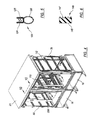
- FIG. 3 is an exploded front isometric view of the modular enclosure system shown in FIGS. 1 and 2 .
- FIG. 4 is a front isometric view of the modular enclosure system shown in FIGS. 1-3 but without side panels and doors.
- FIG. 5 is an enlarged sectional view of a push on bulb seal.
- FIG. 6 is an enlarged sectional view of a pressure sensitive seal.
- FIG. 7 is a partial, broken away, sectional plan view taken along the line 7 — 7 of FIG. 4 .
- FIG. 8 is a partial, broken away, sectional plan view taken generally along the line 8 — 8 of FIG. 3 but showing four vertical comer posts and related elements modified to illustrate a single frame unit having left and right side panels.
- FIG. 9 is a partial, sectional elevation view taken along the line 9 — 9 of FIG. 4 .
- FIG. 10 is a partial, sectional elevation view taken along the line 10 — 10 of FIG. 4 .
- FIGS. 1 and 2 The simplicity and relative inexpensiveness of the inventive modular equipment enclosure system may be seen by reference to FIGS. 1 and 2 .
- the enclosure system 10 includes two chambers 12 , 14 for electronic components situated side-by-side, and placed over two side-by-side battery compartments 16 , 18 .
- a pair of open front doors 20 , 22 are provided to help seal the chambers, and spanning the two chambers is a continuous roof cap or panel 24 .
- To each side of the chambers is a side panel 26 , 28 .
- Also included are two rear doors 30 , 32 .
- An air conditioning system 34 for thermal management is attached to the rear door 30 .
- a pair of skids support each module, such as the first pair of skids 40 , 42 for the left side module and the second pair of skids 44 , 46 for the right side module.
- the various parts of the two segment modular enclosure system 10 are shown in more detail in FIGS. 3 and 4 .
- the skeleton of a segment or module is a frame unit 50 having a top portion or wall 52 and a bottom portion or wall 54 . Between the top wall and the bottom wall are four vertical comer posts, two front comer posts 56 , 58 and two rear comer posts 60 , 62 . (Rear comer post 60 is shown in FIG. 8. ) The comer posts form the front, rear and side portions of the frame unit.
- the top wall 52 and bottom wall 54 are secured to the four vertical corner posts such as by welding.
- the frame unit has a front opening 70 and a rear opening 72 . There are also a left side opening 74 and a right side opening 76 .
- the comer posts and top and bottom walls frame the front, rear and side openings, and the frame unit establishes the chamber for housing electronic equipment.
- each of the openings are sealed against the environment and against tampering.
- the doors cover the front and rear openings and the side panels cover the side openings unless multiple frame units are aligned and attached to one another. In that case the adjoining side openings allow communication between chambers.
- the seal around each side opening abuts each other to close off the side openings as will be explained below.
- a second frame unit 78 is also shown and includes a top wall 80 , a bottom wall 82 and four vertical comer posts 84 , 86 , 88 and 90 . (The comer post 90 is shown in FIG. 7. )
- the second frame unit 78 also includes a front opening 92 , a rear opening 94 , a left side opening 96 and a right side opening 98 .
- Each frame unit includes a plurality of horizontally disposed brackets extending from the two front comer posts of each frame unit to the two rear corner posts, such as the bracket 110 of the frame unit 50 and the bracket 112 of the frame unit 78 .
- a major advantage of the present invention is that the size of the frame unit allows for easy handling, transport and installation when compared to large size integral enclosures which are heavy and bulky.
- the large size enclosures typically require the services of a crane for installation thereby resulting in substantial costs.
- the modular enclosure system of the present invention obviates the need for a crane because of the smaller, much more manageable size modules or segments beginning with a frame unit.
- a segment, even when loaded with electronic equipment, can be passed through a standard thirty-six inch door, moved down a hallway and carried up stairs for rooftop installations.
- Another important advantage is that the enclosure system 10 may be easily expanded when the need arises because the expansion, in the form of additional frame units and related elements, may be assembled on site quickly and economically. Further, panel parts may be added or exchanged easily. All of this may be accomplished without disconnection of the electronic equipment housed within the enclosure system. Because of the structure of the present invention, the enclosure may be assembled, disassembled and reassembled.
- each frame unit includes two sets of factory installed seals, and that these seals may act as primary or secondary seals as will be explained below. It is to be noted that caulking and liquid sealant are not required for assembly or for later expansion.
- the enclosure system can also be taken apart and reassembled and still maintain seal integrity.
- the seal 120 sometimes referred to as a “push-on bulb seal” is an elongated extrusion having an outer tubular portion 122 and a mounting portion of two parallel arms 124 , 125 .
- a flange 126 Around the front opening 70 is a flange 126 .
- Similar flanges 127 , 129 , 131 are formed around all of the openings as are shown and identified.
- the seal 120 is compression fitted or mounted to the flange in a manner well known to those skilled in the art.
- the first type of seal functions by having either another seal or a panel compress the tubular portion 122 so as to close off the region beyond the seal to moisture, dust and the like.
- An identical seal 130 surrounds the rear opening 72 .
- identical seals 132 , 134 surround the left side and right side openings 74 , 76 respectively.
- Additional identical seals 136 , 138 and 140 surround the front, rear and left side openings 92 , 94 , 96 , respectively, of the frame unit 78 .
- Another identical seal surrounds the right side opening 98 of the frame unit 98 but is not shown in FIG. 7 .
- a second type of seal or gasket 146 is mounted vertically along the side of the front comer post 58 .
- the second type of seal has a generally rectangular cross section with an adhesive on one surface 145 and ribs 147 on the opposite surface. The adhesive allows the seal to be pressure sensitive and thereby applied to the frame units with ease.
- Identical seals 148 , 150 , 152 are applied in the same manner to the comer posts 56 , 60 , 62 , respectively.
- Identical seals 146 a , 152 a are applied to the corner posts 58 a , 62 a , respectively.
- Identical seals 154 , 156 are also applied to comer posts 84 , 90 of the frame unit 78 .
- the side panels are all structured to include a central portion 155 , FIG. 8 , an integral edge portion 157 formed about ninety degrees away from the central portion and an integral peripheral border portion 159 formed about ninety degrees away from the edge portion so that the peripheral border portion 159 is generally parallel to the central portion 155 .
- the first type seals 120 , 136 and the second type seals 146 , 154 are primary seals while the first type seals 134 , 140 are secondary seals.
- the seals 120 , 130 , 148 , 150 are primary seals and the seal 132 is a secondary seal.
- the seals are available from vendors and may be acquired from Schlegel Corp. of Rochester, N.Y.
- the front bridge panel 100 and the rear bridge panel 102 connect the two frame units 50 , 78 together in a manner that also compresses the two seals 134 , 140 .
- Each of the bridge panels are connected to their respective vertical corner posts by fasteners, such as the two fasteners 160 , 162 near the front of the enclosure system and the two fasteners 164 , 166 near the rear of the enclosure system.
- a front wall 168 of the front bridge panel 100 and a front wall 170 of the rear bridge panel 102 align flush with the outer surfaces 172 , 173 of the front doors 20 , 22 , respectively, and the outer surfaces 176 , 178 of the rear doors 30 , 32 , respectively.
- the flush aligned look of the enclosure system enhances its aesthetic appeal.
- the seals make abutting contact such that the adjoining left and right side openings, such as the openings 76 , 96 , are entirely sealed or closed off.
- the front and rear seals 120 , 130 are engaged by the doors 20 , 32 , respectively, and these compress the seals when the doors are closed.
- the side seals 132 , 134 and the seals 146 , 146 a , 148 , 150 , 152 , 152 a they are compressed by side panels 26 a , 28 as shown in FIG. 8 , the front and back bridge panels 100 , 102 and by the side seal 140 as shown in FIG. 7 .
- fasteners such as the fasteners 200 , 202 may be used to attach the frame units 50 , 78 to the battery compartments 16 , 18 , respectively.
- FIG. 10 there is illustrated the upper portion of the attached frame units 50 , 78 and the two seals 134 , 140 , the seal 134 being part of the frame unit 50 and the seal 140 being part of the frame unit 78 .
- the top bridge panel 104 is arranged to cover the upper portions of the seals 134 , 140 and is attached to the two frame units 50 , 78 by fasteners 206 , 208 .
- the fasteners 200 , 202 , 206 , 208 may be sealed head insert types available from vendors, such as AVK Industrial Products, a division of AVI Bank Mfg. Inc. of Valencia, Calif.
- the advantage of the seals described here is that there is no need to apply caulking or liquid sealant to the frame units, to the panels or to the doors to ensure sealing worthiness and integrity.
- the seals disclosed here make installation, expansion and part replacement easy and quick as well as consistent. The chance of inconsistent sealing is much less with factory installed seals when compared to the field application of caulking or sealant.
- assembly is quick and easy using industry standard tools and torques. Forming the various elements of the system uses standard metal forming tools and processes and assembly is well known by those skilled in the art.
- the various parts are designed to limit the compression forces on the seals so as not to permanently distort them. Because of this feature, the enclosure may be assembled, disassembled, expanded and reassembled numerous times. For example, to accommodate the rectangular seals 146 , 152 , 154 , 156 , which are about one-quarter inch thick, the front and rear bridge panels 100 , 102 are set back about one-eighth of an inch as shown in FIG. 7 so that when attached, the seal will only be compressed about half of its thickness, well within its elastic limit. In a like manner, the dimensions of the bulb seals, the bridge panels and the flanges are designed to safely compress the bulb seals without permanent distortion and without seal failure.
- the enclosures disclosed above are sealant and caulking free because the first and second types of seals are effective even after long term use or use after the seals have been compressed, released and compressed again. Caulking and sealants may seal but they are not “reuseable”. If such a seal is broken because of disassembly, it is no longer effective.
- the battery compartments 16 , 18 are formed by housings 201 , 203 and include enclosed shelves 209 , 210 . Front and back covers 212 , 214 , 216 and 218 , FIG. 3 , complete formation of the compartments. To prevent tampering, the covers cannot be removed unless the doors are opened.
- the shelves may be about 34.25 inches long, 34.13 inches wide and 14.29 inches high.
- the battery chamber may be about 33.75 inches by 31.5 inches by 13.75 inches.
- Each frame unit is about 34.25 inches long, 34.13 inches wide and 57.75 inches high.
- the doors are each about 31 inches wide and 57.75 inches high.
- the wall thickness for most of the panels, the doors and the frame units is about 0.125 inches.
- a load center 220 Mounted on the side panel 28 is a load center 220 , FIG. 2 , and mounted to the side panel 26 is an RF ground plate 222 , FIG. 1 . Also mounted on the side panel 26 is a cover plate 224 to close an opening for RF cables. If desired, a surge suppressor 226 may be mounted to the side panel 28 above the load center 220 .
- a consolidated receptacle box 228 Inside the frame unit is a consolidated receptacle box 228 , FIG. 3 , to power all 120/240 volt AC equipment mounted in the frame unit 50 and in all adjoining frame units. This feature allows easy field assembly and disassembly of the system thereby eliminating costs connected with adding conduit, wire and circuits.
- the roof cap 24 may be formed with rain gutters 230 , 232 in the form of “J” shaped elements. Similar elements may be formed on the opposite side.
- the rain gutters direct rain water away from the front and rear openings of the frame units.
- An enclosure system may include one frame unit or a multiple number of frame units. Each frame unit is designed to be handled by a single person using a standard two wheel, hand operated dolly. Electronic equipment may also be installed in each frame unit of a multi-segment enclosure system at the factory. The equipment will be connected to community power at the site. If more than one frame unit is used to construct a particular enclosure system, each of the frame units may be limited in the amount of weight that it carries so as to assist in the ease of handling and installation.
- thermal management systems may be easily bolted on to the enclosure system and may be moved or upgraded to accommodate system growth.
- the door with the thermal management system can be removed by simply lifting the door off its hinges without the use of any tools.
- the present enclosure system eliminates caulking and sealant and requires nothing more than standard tools and torques both, for initial assembly or for expansion.
- the modular system of the present invention allows easy field assembly and disassembly thereby eliminating much of the costs usually affiliated with installation and the addition of conduit, wire and circuits.
- the doors are interchangeable and may be either left hand or right hand opening simply by manipulating the door one hundred eighty degrees before assembly.
- Thermal management devices may include air conditioning systems, heat exchangers or fans or any combination of these. Further, the thermal management device may be attached to the doors or the side panels, or mounted above a frame unit or beneath. Still other alternatives will also be equivalent as will many new technologies. There is no desire or intention here to limit in any way the application the doctrine of equivalents.
Landscapes
- Engineering & Computer Science (AREA)
- Power Engineering (AREA)
- Casings For Electric Apparatus (AREA)
Abstract
Description
Claims (12)
Priority Applications (1)
| Application Number | Priority Date | Filing Date | Title |
|---|---|---|---|
| US09/824,490 US6945616B2 (en) | 2001-04-02 | 2001-04-02 | Modular enclosure system for electronic equipment |
Applications Claiming Priority (1)
| Application Number | Priority Date | Filing Date | Title |
|---|---|---|---|
| US09/824,490 US6945616B2 (en) | 2001-04-02 | 2001-04-02 | Modular enclosure system for electronic equipment |
Publications (2)
| Publication Number | Publication Date |
|---|---|
| US20020140325A1 US20020140325A1 (en) | 2002-10-03 |
| US6945616B2 true US6945616B2 (en) | 2005-09-20 |
Family
ID=25241522
Family Applications (1)
| Application Number | Title | Priority Date | Filing Date |
|---|---|---|---|
| US09/824,490 Expired - Fee Related US6945616B2 (en) | 2001-04-02 | 2001-04-02 | Modular enclosure system for electronic equipment |
Country Status (1)
| Country | Link |
|---|---|
| US (1) | US6945616B2 (en) |
Cited By (41)
| Publication number | Priority date | Publication date | Assignee | Title |
|---|---|---|---|---|
| US20060132006A1 (en) * | 2004-12-22 | 2006-06-22 | Robert Schluter | Rack cabinet |
| US20070192817A1 (en) * | 2006-02-13 | 2007-08-16 | Landry Edward T | Fiber distribution hub with outside accessible grounding terminals |
| US20070210686A1 (en) * | 2006-03-13 | 2007-09-13 | Panduit Corp. | Network cabinet |
| US20070210681A1 (en) * | 2006-03-13 | 2007-09-13 | Panduit Corp. | Network cabinet |
| US20070279314A1 (en) * | 2006-06-06 | 2007-12-06 | Brown Brent W | Front and rear removable panel for electronic displays |
| US20080013275A1 (en) * | 2006-05-31 | 2008-01-17 | Apx Enclosures, Inc. | Network expansion enclosure |
| US20080078566A1 (en) * | 2006-09-29 | 2008-04-03 | Paul Kimball Parker | Electrical apparatus cubicle with removable internal side panels |
| US20080080829A1 (en) * | 2006-10-02 | 2008-04-03 | Smith Trevor D | Reskinnable fiber distribution hub |
| US20080174217A1 (en) * | 2006-03-13 | 2008-07-24 | Panduit Corp. | Network Cabinet |
| US20080224578A1 (en) * | 2007-03-13 | 2008-09-18 | Gunter Irmer | Distribution cabinet with a plurality of inner bodies |
| US20090147944A1 (en) * | 2007-10-30 | 2009-06-11 | The Siemon Company | Vertical Patching System |
| US20100102691A1 (en) * | 2006-10-19 | 2010-04-29 | Berthold Sichert Gmbh | Distribution cabinet having a two-piece inner body |
| US20100251583A1 (en) * | 2009-04-01 | 2010-10-07 | Young Electric Sign Company | Incident light management devices and related methods and systems |
| USD630173S1 (en) | 2009-04-20 | 2011-01-04 | Chatsworth Products, Inc. | Cover for electronic equipment cabinet |
| USD632660S1 (en) | 2009-04-20 | 2011-02-15 | Chatsworth Products, Inc. | Cover for electronic equipment cabinet |
| US7893356B2 (en) | 2008-01-07 | 2011-02-22 | Chatsworth Products, Inc. | Cable management accessories |
| US8263867B2 (en) | 2008-01-07 | 2012-09-11 | Chatsworth Products, Inc. | Cable management accessories |
| US20120274194A1 (en) * | 2011-04-28 | 2012-11-01 | Hon Hai Precision Industry Co., Ltd. | Enclosure assembly |
| US20120273436A1 (en) * | 2011-04-29 | 2012-11-01 | Hon Hai Precision Industry Co., Ltd. | Data center container |
| WO2013033844A1 (en) * | 2011-09-07 | 2013-03-14 | Les Solutions Ferroviaire S & C Inc. | Method for providing a new instrument case, an instrument case assembly, and a corresponding kit |
| US20130075056A1 (en) * | 2011-09-26 | 2013-03-28 | Futurewei Technologies, Inc. | Modular System and Framework for Supporting an Enclosure |
| USD684128S1 (en) | 2012-02-10 | 2013-06-11 | Chatsworth Products, Inc. | Containment aisle door |
| US20140036442A1 (en) * | 2012-07-31 | 2014-02-06 | Alcatel-Lucent Deutschland Ag | Outdoor stackable telecommunications equipment cabinet family with flexible thermal and interface management and method of deploying the same |
| US20140076831A1 (en) * | 2012-02-21 | 2014-03-20 | Richard Mathewson | Adaptable Telecommunications Equipment Mounting Frame |
| US8787023B2 (en) | 2010-09-10 | 2014-07-22 | Chatsworth Products, Inc. | Rail mounting clamp for electronic equipment enclosure |
| US20140247539A1 (en) * | 2013-03-04 | 2014-09-04 | Eaton Corporation | Enclosure for electrical distribution equipment and electrical distribution apparatus employing the same |
| US20140252934A1 (en) * | 2013-03-11 | 2014-09-11 | Futrus, Llc | Modular solid surface structure |
| US8901438B2 (en) | 2010-09-10 | 2014-12-02 | Chatsworth Products, Inc. | Electronic equipment cabinet structure |
| US8966821B2 (en) | 2012-09-14 | 2015-03-03 | Panduit Corp. | Dual hinged door mechanism |
| US9055677B2 (en) | 2010-09-10 | 2015-06-09 | Chatsworth Products, Inc. | Cable pass-through panel for electronic equipment enclosure |
| US9351427B2 (en) | 2013-12-17 | 2016-05-24 | Chatsworth Products, Inc. | Electronic equipment enclosure |
| US9560777B2 (en) | 2010-11-08 | 2017-01-31 | Chatsworth Products, Inc. | Door closer mechanism for hot/cold aisle air containment room |
| US9572286B2 (en) | 2013-01-11 | 2017-02-14 | Chatsworth Products, Inc. | Modular thermal isolation barrier for data processing equipment structure |
| US9681560B2 (en) * | 2013-04-07 | 2017-06-13 | Huawei Technologies Co., Ltd. | Cabinet and cabinet group including the same |
| US20170207607A1 (en) * | 2016-01-20 | 2017-07-20 | Lsis Co., Ltd. | Distributing panel |
| US20180295987A1 (en) * | 2017-04-14 | 2018-10-18 | Newage Products, Inc. | Spacer assembly |
| US20190334324A1 (en) * | 2018-04-30 | 2019-10-31 | Rockwell Automation Technologies, Inc. | Systems and methods for a modular enclosure with a door interlock |
| US10575443B2 (en) | 2005-12-22 | 2020-02-25 | Scalematrix | Method and apparatus for a distributed cooling system for electronic equipment enclosures |
| US11246231B2 (en) | 2012-02-10 | 2022-02-08 | Chatsworth Products, Inc. | Door closer mechanism for hot/cold aisle air containment room |
| US11408456B2 (en) | 2019-08-02 | 2022-08-09 | Hoffman Enclosures Inc. | Integral installation aid |
| EP4383486A1 (en) * | 2022-12-08 | 2024-06-12 | Sungrow Power Supply Co., Ltd. | Electrical cabinet, electrical cabinet combination and electrical cabinet working group |
Families Citing this family (24)
| Publication number | Priority date | Publication date | Assignee | Title |
|---|---|---|---|---|
| US20040080244A1 (en) * | 2002-10-28 | 2004-04-29 | Lowther Robert J. | Expandable server cabinet |
| DE10307944B4 (en) * | 2003-02-25 | 2005-08-18 | Berthold Sichert Gmbh | Retractable distribution cabinet |
| US7156475B2 (en) | 2003-04-09 | 2007-01-02 | Gloger Jr Dan R | Mobile storage system for portable electronic election devices |
| DE102004033976B4 (en) * | 2004-07-14 | 2010-09-23 | Berthold Sichert Gmbh | Roof module kit |
| JP2008008089A (en) * | 2006-06-30 | 2008-01-17 | Kobelco Contstruction Machinery Ltd | Guard structure of construction machine |
| CA2556124C (en) * | 2006-08-15 | 2014-04-22 | Inscape Corporation | Stacked cabinet structure with intermediate raceway |
| US7568767B2 (en) * | 2006-12-28 | 2009-08-04 | Suncast Corporation | Snap-together patio bench |
| US7659476B2 (en) * | 2007-04-30 | 2010-02-09 | Adc Telecommunication, Inc. | Frame arrangement for a telecommunications cabinet |
| USD624171S1 (en) | 2007-10-29 | 2010-09-21 | Adc Gmbh | Roof module |
| WO2010088615A1 (en) * | 2009-02-02 | 2010-08-05 | Schweitzer Engineering Laboratories, Inc. | Electric power system control system with selective enclosure |
| US8519859B2 (en) * | 2010-06-01 | 2013-08-27 | Fujitsu Limited | Rack system cover |
| FI8921U1 (en) * | 2010-07-09 | 2010-10-28 | Suomen Cnc Metal Oy | Elcentrallådkonstruktion |
| US8467175B2 (en) * | 2011-02-07 | 2013-06-18 | Dell Products L.P. | System and method for an optimizable rack solution |
| USD686015S1 (en) * | 2011-04-22 | 2013-07-16 | Steelcase Inc. | Furniture portion |
| US8925739B2 (en) * | 2012-07-26 | 2015-01-06 | Lenovo Enterprise Solutions (Singapore) Pte. Ltd. | High-capacity computer rack with rear-accessible side bays |
| DE102014101401A1 (en) * | 2014-02-05 | 2015-08-06 | Rittal Gmbh & Co. Kg | Baying cabinet system |
| DE102015105493B3 (en) * | 2015-04-10 | 2016-08-04 | Rittal Gmbh & Co. Kg | Control cabinet arrangement with a control cabinet row and a cooling unit arranged in it |
| USD789712S1 (en) * | 2015-05-14 | 2017-06-20 | 3 Strike, Llc | Storage container shelf |
| USD763809S1 (en) * | 2015-05-20 | 2016-08-16 | Customs Control Technology Inc. | Electronic component cabinet |
| USD763810S1 (en) * | 2015-05-20 | 2016-08-16 | Customs Control Technology Inc. | Electronic component cabinet |
| USD812249S1 (en) | 2016-06-29 | 2018-03-06 | Schweitzer Engineeing Laboratories, Inc. | Control enclosure |
| WO2019032527A1 (en) * | 2017-08-11 | 2019-02-14 | Commscope Technologies Llc | Modular electronics enclosure |
| DE102019102832B4 (en) * | 2019-02-05 | 2021-09-09 | R. Stahl Schaltgeräte GmbH | Explosion-proof housing and method for its assembly |
| US11160188B2 (en) * | 2020-02-26 | 2021-10-26 | Schweitzer Engineering Laboratories, Inc. | Control panel module assembly devices and techniques |
Citations (11)
| Publication number | Priority date | Publication date | Assignee | Title |
|---|---|---|---|---|
| US4544069A (en) * | 1983-05-26 | 1985-10-01 | Gianfranco Cavallini | Modular elements for composing frames for the construction of cabinet structures and containers for electrical, electromechanical and electronic components, for internal and external use |
| US5020866A (en) * | 1989-11-13 | 1991-06-04 | Gichner Systems Group, Inc. | Enclosure for housing electronic components |
| US5105056A (en) * | 1990-10-26 | 1992-04-14 | Schlegel Corporation | Electromagentic shielding with discontinuous adhesive |
| US5136463A (en) * | 1991-04-05 | 1992-08-04 | Reliance Comm/Tec Corporation | Universal enclosure with electrical panel |
| US5147121A (en) * | 1989-11-13 | 1992-09-15 | Gichner Systems Group, Inc. | Gasket for providing EMI/RFI shielding |
| US5388903A (en) * | 1991-11-27 | 1995-02-14 | Federal-Hoffman, Inc. | Multifaceted modular enclosure frame with integral sub-panel guide system |
| US5545845A (en) * | 1994-11-21 | 1996-08-13 | Dsc Communications Corporation | Transportable weathertight EMI shielded cabinet structure |
| US6164369A (en) * | 1999-07-13 | 2000-12-26 | Lucent Technologies Inc. | Door mounted heat exchanger for outdoor equipment enclosure |
| US6179398B1 (en) * | 1999-01-29 | 2001-01-30 | Michael Alan Martin | Corner piece and cabinet frame |
| US6201694B1 (en) | 1998-04-09 | 2001-03-13 | Telefonaktiebolaget Lm Ericsson (Publ) | Protective structure |
| US6657861B2 (en) * | 2000-02-23 | 2003-12-02 | Krone Gmbh | Distribution cabinet |
-
2001
- 2001-04-02 US US09/824,490 patent/US6945616B2/en not_active Expired - Fee Related
Patent Citations (11)
| Publication number | Priority date | Publication date | Assignee | Title |
|---|---|---|---|---|
| US4544069A (en) * | 1983-05-26 | 1985-10-01 | Gianfranco Cavallini | Modular elements for composing frames for the construction of cabinet structures and containers for electrical, electromechanical and electronic components, for internal and external use |
| US5020866A (en) * | 1989-11-13 | 1991-06-04 | Gichner Systems Group, Inc. | Enclosure for housing electronic components |
| US5147121A (en) * | 1989-11-13 | 1992-09-15 | Gichner Systems Group, Inc. | Gasket for providing EMI/RFI shielding |
| US5105056A (en) * | 1990-10-26 | 1992-04-14 | Schlegel Corporation | Electromagentic shielding with discontinuous adhesive |
| US5136463A (en) * | 1991-04-05 | 1992-08-04 | Reliance Comm/Tec Corporation | Universal enclosure with electrical panel |
| US5388903A (en) * | 1991-11-27 | 1995-02-14 | Federal-Hoffman, Inc. | Multifaceted modular enclosure frame with integral sub-panel guide system |
| US5545845A (en) * | 1994-11-21 | 1996-08-13 | Dsc Communications Corporation | Transportable weathertight EMI shielded cabinet structure |
| US6201694B1 (en) | 1998-04-09 | 2001-03-13 | Telefonaktiebolaget Lm Ericsson (Publ) | Protective structure |
| US6179398B1 (en) * | 1999-01-29 | 2001-01-30 | Michael Alan Martin | Corner piece and cabinet frame |
| US6164369A (en) * | 1999-07-13 | 2000-12-26 | Lucent Technologies Inc. | Door mounted heat exchanger for outdoor equipment enclosure |
| US6657861B2 (en) * | 2000-02-23 | 2003-12-02 | Krone Gmbh | Distribution cabinet |
Cited By (100)
| Publication number | Priority date | Publication date | Assignee | Title |
|---|---|---|---|---|
| US20060132006A1 (en) * | 2004-12-22 | 2006-06-22 | Robert Schluter | Rack cabinet |
| US10575443B2 (en) | 2005-12-22 | 2020-02-25 | Scalematrix | Method and apparatus for a distributed cooling system for electronic equipment enclosures |
| US8569618B2 (en) | 2006-02-13 | 2013-10-29 | Adc Telecommunications, Inc. | Fiber distribution hub with outside accessible grounding terminals |
| US20070192817A1 (en) * | 2006-02-13 | 2007-08-16 | Landry Edward T | Fiber distribution hub with outside accessible grounding terminals |
| US7816602B2 (en) * | 2006-02-13 | 2010-10-19 | Adc Telecommunications, Inc. | Fiber distribution hub with outside accessible grounding terminals |
| US10078192B2 (en) | 2006-02-13 | 2018-09-18 | Commscope Technologies Llc | Fiber distribution hub with outside accessible grounding terminals |
| US9678292B2 (en) | 2006-02-13 | 2017-06-13 | Commscope Technologies Llc | Termination module with termination leg and management leg |
| US8263861B2 (en) | 2006-02-13 | 2012-09-11 | Adc Telecommunications, Inc. | Fiber distribution hub with outside accessible grounding terminals |
| US11119288B2 (en) | 2006-02-13 | 2021-09-14 | Commscope Technologies Llc | Fiber distribution hub |
| US11921338B2 (en) | 2006-02-13 | 2024-03-05 | Commscope Technologies Llc | Fiber distribution hub |
| US20070210686A1 (en) * | 2006-03-13 | 2007-09-13 | Panduit Corp. | Network cabinet |
| US7427713B2 (en) * | 2006-03-13 | 2008-09-23 | Panduit Corp. | Network cabinet |
| US7425678B2 (en) * | 2006-03-13 | 2008-09-16 | Panduit Corp. | Network cabinet |
| US20070210681A1 (en) * | 2006-03-13 | 2007-09-13 | Panduit Corp. | Network cabinet |
| US20080174217A1 (en) * | 2006-03-13 | 2008-07-24 | Panduit Corp. | Network Cabinet |
| US7795532B2 (en) | 2006-03-13 | 2010-09-14 | Panduit Corp. | Network Cabinet |
| US20080013275A1 (en) * | 2006-05-31 | 2008-01-17 | Apx Enclosures, Inc. | Network expansion enclosure |
| US8111208B2 (en) | 2006-06-06 | 2012-02-07 | Young Electric Sign Company | Front and rear removable panel for electronic displays |
| US20070279314A1 (en) * | 2006-06-06 | 2007-12-06 | Brown Brent W | Front and rear removable panel for electronic displays |
| US7586037B2 (en) * | 2006-09-29 | 2009-09-08 | Eaton Corporation | Electrical apparatus cubicle with removable internal side panels |
| US20080078566A1 (en) * | 2006-09-29 | 2008-04-03 | Paul Kimball Parker | Electrical apparatus cubicle with removable internal side panels |
| US7728225B2 (en) | 2006-10-02 | 2010-06-01 | Adc Telecommunications, Inc. | Fiber distribution hub with dual swing frames |
| US20100209066A1 (en) * | 2006-10-02 | 2010-08-19 | Adc Telecommunications, Inc. | Fiber distribution hub with dual swing frames |
| US8357851B2 (en) | 2006-10-02 | 2013-01-22 | Adc Telecommunications, Inc. | Fiber distribution hub with dual swing frames |
| US20110083310A1 (en) * | 2006-10-02 | 2011-04-14 | Adc Telecommunications, Inc. | Reskinnable fiber distribution hub |
| US7964793B2 (en) | 2006-10-02 | 2011-06-21 | Adc Telecommunications, Inc. | Fiber distribution hub with dual swing frames |
| US7711234B2 (en) | 2006-10-02 | 2010-05-04 | Adc Telecommunications, Inc. | Reskinnable fiber distribution hub |
| US8009955B2 (en) | 2006-10-02 | 2011-08-30 | Adc Telecommunications, Inc. | Reskinnable fiber distribution hub |
| US20080080829A1 (en) * | 2006-10-02 | 2008-04-03 | Smith Trevor D | Reskinnable fiber distribution hub |
| US20100102691A1 (en) * | 2006-10-19 | 2010-04-29 | Berthold Sichert Gmbh | Distribution cabinet having a two-piece inner body |
| US8076574B2 (en) * | 2007-03-13 | 2011-12-13 | Adc Gmbh | Distribution cabinet with a plurality of inner bodies |
| US20080224578A1 (en) * | 2007-03-13 | 2008-09-18 | Gunter Irmer | Distribution cabinet with a plurality of inner bodies |
| US20090147944A1 (en) * | 2007-10-30 | 2009-06-11 | The Siemon Company | Vertical Patching System |
| US8153893B2 (en) * | 2007-10-30 | 2012-04-10 | The Siemon Company | Vertical patching system |
| US8273989B2 (en) | 2008-01-07 | 2012-09-25 | Chatsworth Products, Inc. | Cable management accessories |
| US8138419B2 (en) | 2008-01-07 | 2012-03-20 | Chatsworth Products, Inc. | Cable management accessories |
| US8330043B2 (en) | 2008-01-07 | 2012-12-11 | Chatsworth Products, Inc. | Cable management accessories |
| US7893356B2 (en) | 2008-01-07 | 2011-02-22 | Chatsworth Products, Inc. | Cable management accessories |
| US7999183B2 (en) | 2008-01-07 | 2011-08-16 | Chatsworth Products, Inc. | Cable management accessories |
| US8263867B2 (en) | 2008-01-07 | 2012-09-11 | Chatsworth Products, Inc. | Cable management accessories |
| US20100251583A1 (en) * | 2009-04-01 | 2010-10-07 | Young Electric Sign Company | Incident light management devices and related methods and systems |
| USD630173S1 (en) | 2009-04-20 | 2011-01-04 | Chatsworth Products, Inc. | Cover for electronic equipment cabinet |
| USD632660S1 (en) | 2009-04-20 | 2011-02-15 | Chatsworth Products, Inc. | Cover for electronic equipment cabinet |
| US10653025B2 (en) | 2010-09-10 | 2020-05-12 | Chatsworth Products, Inc. | Cable pass-through panel for electronic equipment enclosure |
| US9055677B2 (en) | 2010-09-10 | 2015-06-09 | Chatsworth Products, Inc. | Cable pass-through panel for electronic equipment enclosure |
| US9781852B2 (en) | 2010-09-10 | 2017-10-03 | Chatsworth Products, Inc. | Cable pass-through panel for electronic equipment enclosure |
| US8787023B2 (en) | 2010-09-10 | 2014-07-22 | Chatsworth Products, Inc. | Rail mounting clamp for electronic equipment enclosure |
| US12108553B2 (en) | 2010-09-10 | 2024-10-01 | Chatsworth Products, Inc. | Cable pass-through panel for electronic equipment enclosure |
| US9980400B2 (en) | 2010-09-10 | 2018-05-22 | Chatsworth Products, Inc. | Rail seal for electronic equipment enclosure |
| US8901438B2 (en) | 2010-09-10 | 2014-12-02 | Chatsworth Products, Inc. | Electronic equipment cabinet structure |
| US11792948B2 (en) | 2010-09-10 | 2023-10-17 | Chatsworth Products, Inc. | Cable pass-through panel for electronic equipment enclosure |
| US10237994B2 (en) | 2010-09-10 | 2019-03-19 | Chatsworth Products, Inc. | Vertical mounting rail with cable management features |
| US10178784B2 (en) | 2010-09-10 | 2019-01-08 | Chatsworth Products, Inc. | Rail seal for electronic equipment enclosure |
| US11464123B2 (en) | 2010-09-10 | 2022-10-04 | Chatsworth Products, Inc. | Method of adapting an electronic equipment enclosure for cable management |
| US9814159B2 (en) | 2010-09-10 | 2017-11-07 | Chatsworth Products, Inc. | Rail seal for electronic equipment enclosure |
| US9408326B2 (en) | 2010-09-10 | 2016-08-02 | Chatsworth Products, Inc. | Electronic equipment cabinet structure |
| US10588227B2 (en) | 2010-09-10 | 2020-03-10 | Chatsworth Products, Inc. | Vertical mounting rail with cable management features |
| US11039543B2 (en) | 2010-09-10 | 2021-06-15 | Chatsworth Products, Inc. | Vertical mounting rail with cable management features |
| US9642270B2 (en) | 2010-09-10 | 2017-05-02 | Chatsworth Products, Inc. | Rail seal for electronic equipment enclosure |
| US9560777B2 (en) | 2010-11-08 | 2017-01-31 | Chatsworth Products, Inc. | Door closer mechanism for hot/cold aisle air containment room |
| US10362695B2 (en) | 2010-11-08 | 2019-07-23 | Chatsworth Products, Inc. | Door closer mechanism for hot/cold aisle air containment room |
| US20120274194A1 (en) * | 2011-04-28 | 2012-11-01 | Hon Hai Precision Industry Co., Ltd. | Enclosure assembly |
| US20120273436A1 (en) * | 2011-04-29 | 2012-11-01 | Hon Hai Precision Industry Co., Ltd. | Data center container |
| WO2013033844A1 (en) * | 2011-09-07 | 2013-03-14 | Les Solutions Ferroviaire S & C Inc. | Method for providing a new instrument case, an instrument case assembly, and a corresponding kit |
| US20130075056A1 (en) * | 2011-09-26 | 2013-03-28 | Futurewei Technologies, Inc. | Modular System and Framework for Supporting an Enclosure |
| US8599540B2 (en) * | 2011-09-26 | 2013-12-03 | Futurewei Technologies, Inc. | Modular system and framework for supporting an enclosure |
| US11246231B2 (en) | 2012-02-10 | 2022-02-08 | Chatsworth Products, Inc. | Door closer mechanism for hot/cold aisle air containment room |
| USD684128S1 (en) | 2012-02-10 | 2013-06-11 | Chatsworth Products, Inc. | Containment aisle door |
| US20140076831A1 (en) * | 2012-02-21 | 2014-03-20 | Richard Mathewson | Adaptable Telecommunications Equipment Mounting Frame |
| US20140036442A1 (en) * | 2012-07-31 | 2014-02-06 | Alcatel-Lucent Deutschland Ag | Outdoor stackable telecommunications equipment cabinet family with flexible thermal and interface management and method of deploying the same |
| US8966821B2 (en) | 2012-09-14 | 2015-03-03 | Panduit Corp. | Dual hinged door mechanism |
| US12063758B2 (en) | 2013-01-11 | 2024-08-13 | Chatsworth Products, Inc. | Modular thermal isolation barrier for data processing equipment structure |
| US9795060B2 (en) | 2013-01-11 | 2017-10-17 | Chatsworth Products, Inc. | Modular thermal isolation barrier for data processing equipment structure |
| US10375861B2 (en) | 2013-01-11 | 2019-08-06 | Chatsworth Products, Inc. | Modular thermal isolation barrier for data processing equipment structure |
| US11647610B2 (en) | 2013-01-11 | 2023-05-09 | Chatsworth Products, Inc. | Modular thermal isolation barrier for data processing equipment structure |
| US10595442B2 (en) | 2013-01-11 | 2020-03-17 | Chatsworth Products, Inc. | Data processing equipment structure |
| US9572286B2 (en) | 2013-01-11 | 2017-02-14 | Chatsworth Products, Inc. | Modular thermal isolation barrier for data processing equipment structure |
| US9077160B2 (en) * | 2013-03-04 | 2015-07-07 | Eaton Corporation | Enclosure for electrical distribution equipment and electrical distribution apparatus employing the same |
| US20140247539A1 (en) * | 2013-03-04 | 2014-09-04 | Eaton Corporation | Enclosure for electrical distribution equipment and electrical distribution apparatus employing the same |
| US20140252934A1 (en) * | 2013-03-11 | 2014-09-11 | Futrus, Llc | Modular solid surface structure |
| US8950832B2 (en) * | 2013-03-11 | 2015-02-10 | Futrus, Llc | Modular solid surface structure |
| US9681560B2 (en) * | 2013-04-07 | 2017-06-13 | Huawei Technologies Co., Ltd. | Cabinet and cabinet group including the same |
| US9549487B2 (en) | 2013-12-17 | 2017-01-17 | Chatsworth Products, Inc. | Electronic equipment enclosure |
| US10674634B2 (en) | 2013-12-17 | 2020-06-02 | Chatsworth Products, Inc. | Electronic equipment enclosure |
| US9949406B2 (en) | 2013-12-17 | 2018-04-17 | Chatsworth Products, Inc. | Electronic equipment enclosure |
| US10356951B2 (en) | 2013-12-17 | 2019-07-16 | Chatsworth Products, Inc. | Electronic equipment enclosure |
| US11083108B2 (en) | 2013-12-17 | 2021-08-03 | Chatsworth Products, Inc. | Electronic equipment enclosure |
| US9420727B2 (en) | 2013-12-17 | 2016-08-16 | Chatsworth Products, Inc. | Electronic equipment enclosure |
| US9351427B2 (en) | 2013-12-17 | 2016-05-24 | Chatsworth Products, Inc. | Electronic equipment enclosure |
| US11985799B2 (en) | 2013-12-17 | 2024-05-14 | Chatsworth Products, Inc. | Electronic equipment enclosure |
| US10461510B2 (en) * | 2016-01-20 | 2019-10-29 | Lsis Co., Ltd. | Modular distributing panel including a transformer |
| US20170207607A1 (en) * | 2016-01-20 | 2017-07-20 | Lsis Co., Ltd. | Distributing panel |
| US10687621B2 (en) * | 2017-04-14 | 2020-06-23 | Newage Products Inc. | Spacer assembly |
| US20180295987A1 (en) * | 2017-04-14 | 2018-10-18 | Newage Products, Inc. | Spacer assembly |
| US20190334324A1 (en) * | 2018-04-30 | 2019-10-31 | Rockwell Automation Technologies, Inc. | Systems and methods for a modular enclosure with a door interlock |
| US10811853B2 (en) * | 2018-04-30 | 2020-10-20 | Rockwell Automation Technologies, Inc. | Systems and methods for a modular enclosure with a door interlock |
| US20220378204A1 (en) * | 2019-08-02 | 2022-12-01 | Hoffman Enclosures Inc. | Integral Installation Aid |
| US11815114B2 (en) * | 2019-08-02 | 2023-11-14 | Hoffman Enclosures Inc. | Integral installation aid |
| US11408456B2 (en) | 2019-08-02 | 2022-08-09 | Hoffman Enclosures Inc. | Integral installation aid |
| EP4383486A1 (en) * | 2022-12-08 | 2024-06-12 | Sungrow Power Supply Co., Ltd. | Electrical cabinet, electrical cabinet combination and electrical cabinet working group |
Also Published As
| Publication number | Publication date |
|---|---|
| US20020140325A1 (en) | 2002-10-03 |
Similar Documents
| Publication | Publication Date | Title |
|---|---|---|
| US6945616B2 (en) | Modular enclosure system for electronic equipment | |
| US7762731B2 (en) | Environmentally sealed enclosure | |
| US9142939B2 (en) | Method and apparatus for mounting a power converter | |
| US6581342B1 (en) | Blast protective window | |
| US4215517A (en) | Auxilliary window for industrial and commercial applications | |
| US20030174487A1 (en) | Enclosure with shielded power compartment and methods of shielding enclosures | |
| WO2005043048A1 (en) | Frame construction for an air handling unit | |
| TW360737B (en) | Modular louver system | |
| TW200402504A (en) | Improved exterior vision panel system | |
| CA3022421C (en) | Enclosure for electronic components | |
| US20020036892A1 (en) | Amplifier | |
| US8800243B2 (en) | Modular work station with air collector | |
| UA46041C2 (en) | HOUSING USED OUTDOORS AND HOLLOW PROFILE RAILS FOR ITS ASSEMBLY | |
| US20220248556A1 (en) | Small Cell Telecommunication Structure | |
| KR100283195B1 (en) | Hingeless enclosure for display systems | |
| AU2009251099B2 (en) | Weatherproof Double Door Sealing Arrangement | |
| CN220222020U (en) | Fan mounting structure, container for setting special computing equipment, connecting frame and supporting frame | |
| EP0863267A2 (en) | House unit, and contruction of house unit frame | |
| US4289120A (en) | Solar heat collecting apparatus | |
| AU2009251100A1 (en) | Weatherproof Frame Sealing Arrangement | |
| CN104937792B (en) | The outdoor cabinet framework of anti-entrance | |
| CN209433337U (en) | A kind of spliced computer cabinet shell | |
| JP3078174B2 (en) | Curtain wall unit | |
| JP3871250B2 (en) | Corner wall structure of curtain wall | |
| US5638648A (en) | Window door stamped radius |
Legal Events
| Date | Code | Title | Description |
|---|---|---|---|
| AS | Assignment |
Owner name: MARCONI COMMUNICATIONS, INC., OHIO Free format text: ASSIGNMENT OF ASSIGNORS INTEREST;ASSIGNORS:WEBSTER, JAMES W.;LOCKHART, JULIUS C.;REEL/FRAME:012009/0384;SIGNING DATES FROM 20010423 TO 20010424 |
|
| AS | Assignment |
Owner name: MARCONI INTELLECTUAL PROPERTY ( RINGFENCE) INC., P Free format text: ASSIGNMENT OF ASSIGNORS INTEREST;ASSIGNOR:MARCONI COMMUNICATIONS, INC.;REEL/FRAME:014675/0855 Effective date: 20031028 |
|
| AS | Assignment |
Owner name: EMERSUB XCII, INC., MISSOURI Free format text: ASSIGNMENT OF ASSIGNORS INTEREST;ASSIGNOR:MARCONI INTELLECTUAL PROPERTY (RINGFENCE) INC.;REEL/FRAME:015394/0222 Effective date: 20040812 |
|
| AS | Assignment |
Owner name: EMERSON NETWORK POWER, ENERGY SYSTEMS, NORTH AMERI Free format text: CHANGE OF NAME;ASSIGNOR:EMERSUB XCII, INC.;REEL/FRAME:015452/0663 Effective date: 20041119 |
|
| FPAY | Fee payment |
Year of fee payment: 4 |
|
| FPAY | Fee payment |
Year of fee payment: 8 |
|
| AS | Assignment |
Owner name: JPMORGAN CHASE BANK, N.A., AS COLLATERAL AGENT, NE Free format text: SECURITY AGREEMENT;ASSIGNORS:ALBER CORP.;ASCO POWER TECHNOLOGIES, L.P.;AVOCENT CORPORATION;AND OTHERS;REEL/FRAME:040783/0148 Effective date: 20161130 Owner name: JPMORGAN CHASE BANK, N.A., AS COLLATERAL AGENT, NEW YORK Free format text: SECURITY AGREEMENT;ASSIGNORS:ALBER CORP.;ASCO POWER TECHNOLOGIES, L.P.;AVOCENT CORPORATION;AND OTHERS;REEL/FRAME:040783/0148 Effective date: 20161130 |
|
| AS | Assignment |
Owner name: JPMORGAN CHASE BANK, N.A., AS COLLATERAL AGENT, NE Free format text: SECURITY AGREEMENT;ASSIGNORS:ALBER CORP.;ASCO POWER TECHNOLOGIES, L.P.;AVOCENT CORPORATION;AND OTHERS;REEL/FRAME:040797/0615 Effective date: 20161130 Owner name: JPMORGAN CHASE BANK, N.A., AS COLLATERAL AGENT, NEW YORK Free format text: SECURITY AGREEMENT;ASSIGNORS:ALBER CORP.;ASCO POWER TECHNOLOGIES, L.P.;AVOCENT CORPORATION;AND OTHERS;REEL/FRAME:040797/0615 Effective date: 20161130 |
|
| REMI | Maintenance fee reminder mailed | ||
| LAPS | Lapse for failure to pay maintenance fees |
Free format text: PATENT EXPIRED FOR FAILURE TO PAY MAINTENANCE FEES (ORIGINAL EVENT CODE: EXP.) |
|
| STCH | Information on status: patent discontinuation |
Free format text: PATENT EXPIRED DUE TO NONPAYMENT OF MAINTENANCE FEES UNDER 37 CFR 1.362 |
|
| FP | Lapsed due to failure to pay maintenance fee |
Effective date: 20170920 |
|
| AS | Assignment |
Owner name: VERTIV IT SYSTEMS, INC. (F/K/A AVOCENT REDMOND CORP.), OHIO Free format text: RELEASE BY SECURED PARTY;ASSIGNOR:JPMORGAN CHASE BANK, N.A.;REEL/FRAME:052065/0666 Effective date: 20200302 Owner name: ELECTRICAL RELIABILITY SERVICES, INC., OHIO Free format text: RELEASE BY SECURED PARTY;ASSIGNOR:JPMORGAN CHASE BANK, N.A.;REEL/FRAME:052065/0666 Effective date: 20200302 Owner name: VERTIV IT SYSTEMS, INC. (F/K/A AVOCENT FREMONT, LLC), OHIO Free format text: RELEASE BY SECURED PARTY;ASSIGNOR:JPMORGAN CHASE BANK, N.A.;REEL/FRAME:052065/0666 Effective date: 20200302 Owner name: VERTIV CORPORATION (F/K/A EMERSON NETWORK POWER, ENERGY SYSTEMS, NORTH AMERICA, INC.), OHIO Free format text: RELEASE BY SECURED PARTY;ASSIGNOR:JPMORGAN CHASE BANK, N.A.;REEL/FRAME:052065/0666 Effective date: 20200302 Owner name: VERTIV IT SYSTEMS, INC. (F/K/A AVOCENT HUNTSVILLE, LLC), OHIO Free format text: RELEASE BY SECURED PARTY;ASSIGNOR:JPMORGAN CHASE BANK, N.A.;REEL/FRAME:052065/0666 Effective date: 20200302 Owner name: VERTIV IT SYSTEMS, INC. (F/K/A AVOCENT CORPORATION), OHIO Free format text: RELEASE BY SECURED PARTY;ASSIGNOR:JPMORGAN CHASE BANK, N.A.;REEL/FRAME:052065/0666 Effective date: 20200302 Owner name: VERTIV CORPORATION (F/K/A LIEBERT CORPORATION), OHIO Free format text: RELEASE BY SECURED PARTY;ASSIGNOR:JPMORGAN CHASE BANK, N.A.;REEL/FRAME:052065/0666 Effective date: 20200302 Owner name: VERTIV CORPORATION (F/K/A ALBER CORP.), OHIO Free format text: RELEASE BY SECURED PARTY;ASSIGNOR:JPMORGAN CHASE BANK, N.A.;REEL/FRAME:052065/0666 Effective date: 20200302 |