JP2009065577A - Imaging apparatus and imaging method - Google Patents
Imaging apparatus and imaging method Download PDFInfo
- Publication number
- JP2009065577A JP2009065577A JP2007233541A JP2007233541A JP2009065577A JP 2009065577 A JP2009065577 A JP 2009065577A JP 2007233541 A JP2007233541 A JP 2007233541A JP 2007233541 A JP2007233541 A JP 2007233541A JP 2009065577 A JP2009065577 A JP 2009065577A
- Authority
- JP
- Japan
- Prior art keywords
- face
- image
- guide
- imaging
- arrangement area
- Prior art date
- Legal status (The legal status is an assumption and is not a legal conclusion. Google has not performed a legal analysis and makes no representation as to the accuracy of the status listed.)
- Pending
Links
Images


Landscapes
- Studio Devices (AREA)
Abstract
Description
本発明は、カメラなどの撮像装置および撮像方法に関するもので、特に撮影者自らが被写体となって撮影する場合に好適な撮像装置および撮像方法に関するものである。 The present invention relates to an image pickup apparatus such as a camera and an image pickup method, and more particularly to an image pickup apparatus and an image pickup method suitable for a case where a photographer himself takes a picture as a subject.
カメラなどの撮像装置により撮像装置の所有者自らが被写体となって撮影するには、以下のような方法をとる。
1.カメラを三脚に固定し、セルフタイマ機能を使用して撮影する。
2.近くにいる第三者に撮影操作を依頼して撮影を行う。
3.撮影者自身が撮影レンズを自分に向けた状態でカメラ本体を手指で把持しつつ腕を伸ばして撮影する。
The following method is used for photographing with the imaging device such as a camera as the subject itself.
1. Fix the camera on a tripod and take a picture using the self-timer function.
2. Request a shooting operation from a nearby third party and take a picture.
3. The photographer himself shoots with his arms extended while holding the camera body with his / her fingers with the photographic lens facing him.
上記3.の方法で撮影する場合、画面内に撮影者自らが入っているかどうか、さらには、撮影者自らが被写体として画面上のどの位置にあるのかすなわち構図がどのようになっているのかの確認が問題になる。この問題を解決するために、カメラにミラーユニットを設け、撮影者自身を被写体として撮影する際にミラーをカメラから起立させて撮影者自身に向け、ミラーに写る撮影者自身の位置を確認した上で撮影ができるようにしたカメラが提案されている(例えば、特許文献1参照)。 3. above. When shooting with this method, it is a problem to check whether the photographer himself is in the screen, and also where the photographer himself is on the screen as the subject, that is, how the composition is become. In order to solve this problem, a mirror unit is provided in the camera, and when shooting the photographer himself as a subject, the mirror stands up from the camera and faces the photographer himself, and then confirms the position of the photographer himself in the mirror. There has been proposed a camera that can be used for shooting (see, for example, Patent Document 1).
また、レンズカバーの表面を鏡面状に形成しておき、シャッタボタンの操作に応じてレンズカバーが開閉して撮影が行われるようにしたデジタルカメラが提案されている(例えば、特許文献2参照)。いわゆる「自分撮りモード」で撮影を行う場合、撮影者はレンズカバーに写っている像により、被写体としての撮影者自身の画像が、撮影者が意図しているとおりの位置にあるかどうかを確認することができる。 In addition, a digital camera has been proposed in which a lens cover surface is formed in a mirror shape, and shooting is performed by opening and closing the lens cover in accordance with an operation of a shutter button (for example, see Patent Document 2). . When shooting in the so-called “selfie mode”, the photographer confirms whether the photographer's own image as the subject is in the position as intended by the photographer by the image on the lens cover. can do.
特許文献1,2に記載されているカメラのほかに、液晶モニタを回転させる機構を設け、液晶モニタを撮影者自身に向けることにより、液晶モニタに表示されるスルー画像より撮影者自身の位置を確認した上で撮影ができるようにしたデジタルカメラがある。また、レンズ部分を回転させる機構を設け、液晶モニタを撮影者自身に向けた状態でレンズも撮影者自身に向けることにより、液晶モニタに表示されるスルー画像より撮影者自身の位置を確認した上で撮影ができるようにしたデジタルカメラもある。
In addition to the cameras described in
さらに、レンズおよび撮像素子をカメラの前後に設け、撮影者自身を被写体として撮影する際には、カメラ後方のレンズおよび撮像素子が有効になるように切り替えることにより、液晶モニタに表示されるスルー画像より撮影者自身の位置を確認した上で撮影することができるデジタルカメラもある。 Furthermore, when a lens and an image sensor are provided in front of and behind the camera and the photographer himself / herself is photographed as a subject, a through image displayed on the liquid crystal monitor is switched by switching the lens and the image sensor behind the camera to be effective. There are also digital cameras that can take pictures after confirming the position of the photographer.
さらに、本願発明の技術思想に関連のある従来の技術として、特許文献3には、「自分撮り」や、「依頼撮り」において、ユーザ自身すなわち被写体となる撮影者自身が撮影時における手ぶれ発生を認識できるようにする目的で、「自分撮りモード」や「依頼撮りモード」による撮影時、カメラ前面のセルフタイマランプを点滅表示させ、ユーザに対して手ぶれ発生を告知するカメラが開示されている。
Further, as a conventional technique related to the technical idea of the present invention,
特許文献4には、撮影者自身を被写体として撮影する場合において、撮影者にピントが合っていない状態で撮影が行われることによる撮影失敗を防止する目的で、被写体が撮影光学系の最至近距離よりも近くに位置している状態にあるか否かを検出するための検出手段と、この検出手段により被写体が撮影光学系の最至近距離よりも近くに位置している状態にあると検出されたときに発光して警告する、カメラ本体の前面に設けられた発光手段とを有するカメラが開示されている。一般的にカメラが具備している表示手段を用いて、それを本来の表示とは別のカメラの状態を告知することに利用するものである。
In
特許文献5には、良好な構図の画像を容易に撮影することができる撮影装置を提供する目的で、撮影する画像の中から人物の顔の位置を顔検出部によって検出し、その顔の位置が画像内の所定位置に配置されるように、修正すべきカメラの向きを音声ガイドとして出力する撮影装置が開示されている。顔検出手段で検出された人物の顔の位置が、画像内の所定位置に位置するようにガイドする点で、後述の本願発明の一部構成部分と類似している。
In
撮影者自身がカメラを保持して撮影者自身を被写体として撮影するために、特許文献1に記載されているカメラのように、ミラーを付加し、特許文献2に記載されているカメラのように、液晶モニタを回転させる機構を付加し、さらに、レンズおよび撮像素子を複数備えたカメラは、いずれも、デザイン上の制約があり、これに加えて、カメラ寸法の大型化、コストアップといった問題があった。
In order for the photographer to hold the camera and photograph the photographer himself as a subject, a mirror is added like the camera described in
本発明は、このような従来技術の問題点を解消するためになされたもので、撮影者自身が撮像装置を持って撮影者が自らを被写体として撮影するとき、カメラに特別な機構を付加しなくても、撮影者の顔をカメラの撮影画角内に確実に入れて撮影することができる撮像装置および撮像方法を提供することを目的とする。 The present invention has been made to solve such problems of the prior art, and when a photographer owns an imaging device and the photographer photographs the subject as a subject, a special mechanism is added to the camera. It is an object of the present invention to provide an imaging apparatus and an imaging method that can capture an image of a photographer's face within a shooting angle of view of a camera without being photographed.
本発明は、固体撮影素子面に結像する撮影画像の中から人物の顔の位置を検出する顔検出手段と、画像内の所定位置に所定サイズで、前記顔検出手段で検出された人物の顔を配置する領域を設定する顔配置領域設定手段と、前記顔検出手段で検出された人物の顔の位置が、前記顔配置設定手段により設定された顔配置領域内に位置するように案内するガイド手段と、を備えていることを最も主要な特徴とする。 The present invention relates to a face detection means for detecting the position of a person's face from a photographed image formed on the surface of a solid-state imaging element, and a human face detected by the face detection means at a predetermined position in the image at a predetermined size. Face placement area setting means for setting a face placement area, and guiding the face position of the person detected by the face detection means to be within the face placement area set by the face placement setting means And a guide means.
カメラに特別な機構を付加しなくても、撮影者が自らを被写体として撮影するとき、撮影者の顔をカメラの撮影画角内へ確実に入れて撮影することができる。
撮影者の顔検出状態を、カメラが一般的に具備しているLEDやランプ、ブザー、スピーカーなどの部材を利用して状態を知らせることができ、新たな機能部品を付加しなくても、新たな撮影ガイド機能を付加することができる。
Even without adding a special mechanism to the camera, when the photographer shoots himself / herself as a subject, the photographer's face can be surely placed within the shooting angle of view of the camera.
The camera's face detection status can be informed using the LEDs, lamps, buzzers, speakers, etc., which cameras generally have, and can be updated without adding new functional parts. It is possible to add a photographing guide function.
以下、本発明にかかる撮像装置の実施例について図面を参照しながら説明する。
本発明にかかる撮像装置は、レンズを通った光を固体撮像素子で受け、固体撮像素子のアナログ信号をデジタル信号に変換してメモリに記録するデジタル方式の撮像装置、例えばデジタルカメラを想定している。まず、撮像装置としてのデジタルカメラの実施例についてその外観に現れている構成を説明する。
Embodiments of an image pickup apparatus according to the present invention will be described below with reference to the drawings.
An imaging apparatus according to the present invention assumes a digital imaging apparatus, for example, a digital camera, which receives light passing through a lens by a solid-state imaging element, converts an analog signal of the solid-state imaging element into a digital signal, and records the signal in a memory. Yes. First, a configuration appearing in the appearance of an embodiment of a digital camera as an imaging device will be described.
図1において、デジタルカメラ本体30の前面および上面には、POWER(電源)ボタン1、シャッタボタン2、フラッシュ発光部3、AF(「オートフォーカス」を意味する。以下同じ)補助光/セルフタイマランプ4、レンズカバー5、マイク6、スピーカー7、レンズ8が配置されている。ただし、レンズ8は沈胴式であって、図1(a)はカメラ本体30内にレンズ8が収納され、レンズカバー5が閉じられることによってレンズ8は外から見ることはできない。図1(b)はレンズ8がカメラ本体30からカメラ本体30の前面側に進出して撮影可能な態様になっている。
In FIG. 1, a
図2(a)に示すように、デジタルカメラ本体30の背面には、液晶モニタ9、ズームレバー(望遠)/(広角)10、モード切替スイッチ11、再生ボタン12、ADJ.ボタン13、削除/セルフタイマボタン14、↑/MODEボタン15、→/クイックレビューボタン16、MENU/OKボタン17、↓/マクロボタン18、←/フラッシュボタン19、DISP.ボタン20、AV出力端子21、USB端子22が配置されている。図2(b)に示すように、デジタルカメラ本体30の底面には、三脚ネジ穴23、バッテリ/カードカバー24が配置されている。バッテリ/カードカバー24を開けると、バッテリ挿入部とカード挿入部が露呈し、ここにバッテリと記憶カードを装填するように構成されている。
As shown in FIG. 2A, on the back of the
モード切替スイッチ11は、2ポジションのスライドスイッチで構成されており、その位置によりデジタルカメラの動作モードを設定できる。静止画撮影や動画撮影などのカメラの操作は、このモード切替スイッチ11を切り替えてから行う。デジタルカメラのモードは、「シーンモード」、「静止画撮影モード」の2種類ある。「静止画撮影モード」は、静止画を撮影するときに使用し、「シーンモード」は、「ポートレートモード」、「フェイスモード」、「スポーツモード」、「遠景モード」、「夜景モード」、「高感度モード」、「ズームマクロモード」、「白黒モード」、「セピアモード」、「斜め補正モード」、「文字モード」、「動画撮影モード」などがある。再生ボタン12は、デジタルカメラのモードを「再生モード」へ指示するボタンとして機能する。撮影モード時、このボタンが押されると、最後に撮った静止画が液晶モニタ9に表示される。
The
レンズ8は、沈胴式のズームレンズで構成されており、POWER(電源)ボタン1によりカメラの電源が投入され、モード切替スイッチ11によりカメラのモードを撮影モードに設定することにより、デジタルカメラ本体30から繰り出される。ズームレバー(望遠)/(広角)10は、シャッタボタン2の周囲にある3ポジションのレバーで構成されており、レンズ8のズームを指示する手段として機能する。デジタルカメラは、撮影モードに設定されているとき、上記ズームレバー(望遠)/(広角)10を望遠側に操作すると、レンズ8は望遠側へのズームを行い、ズームレバー(望遠)/(広角)10を広角側に操作すると、レンズ8は広角側へのズームを行い、レンズ8の焦点距離を連続的に変化させる。また、再生モードに設定されているとき、ズームレバー(望遠)/(広角)10を操作することにより、再生中の画像の表示倍率を変化させることができる。すなわち、ズームレバー(望遠)/(広角)10を広角側へ操作すると、再生中の画像が縮小表示され、ズームレバー(望遠)/(広角)10を望遠側へ操作すると、再生中の画像が拡大表示される。
The
シャッタボタン2は、2段式のスイッチで構成されており、半押し操作と押し切り操作が可能である。デジタルカメラは、このシャッタボタン2の半押し操作により、AE(「自動露出」の意味。以下同じ)/AFが作動し、押し切り操作により、AWB(オートホワイトバランス」の意味。以下同じ)が作動し撮影を実行する。液晶モニタ9は、カラー表示が可能な液晶ディスプレイで構成されており、再生モード時には撮影済み画像を表示するための画像表示パネルとして利用されるとともに、各種設定操作を行なう際のユーザインターフェース表示パネルとして利用される。また、撮影モード時には、必要に応じてライブビュー画像が表示されて、画角確認用の電子ファインダとして利用される。
The
「↑/MODEボタン15」、「→/クイックレビューボタン16」、「↓/マクロボタン18」、「←/フラッシュボタン19」は、それぞれ上下左右4方向の指示を入力する方向指示手段として機能する。例えば、メニュー画面でメニュー項目の選択などに使用される。MENU/OKボタン17は、各モードの通常画面からメニュー画面への遷移を指示するボタン(MENUボタン)として機能するととともに、選択内容の確定、処理の実行等を指示するボタン(OKボタン)として機能する。
The “↑ /
DISP.ボタン20は、液晶モニタ9のマークの表示/非表示を切り替えるなど、画面の表示状態の変更を指示するボタンとして機能する。また、撮影モード時に、このボタンが1回押されるごとに、ヒストグラム表示→グリッドガイド表示→表示なし→液晶モニタオフ→通常のマーク表示→ヒストグラム表示→・・・とように順に切り替えられる。再生モード時に、このボタンが1回押されるごとに、ヒストグラム表示→ハイライト表示→表示なし→通常のマーク表示→ヒストグラム表示→・・・と切り替えられる。また、このボタンは、入力操作のキャンセルや一つ前の操作状態に戻すことを指示するボタンとしても機能する。
DISP. The
現在、図1、図2に示すような形態のデジタルカメラが最も普及しているが、いわゆる自分撮りを容易にするための複雑な機構は一般的に備えていない。このような形態のデジタルカメラで「自分撮り」を行う場合、撮影者には液晶モニタ9が見えないため、ライブビュー画像を見ることができず、撮影者の顔が、画角からはみ出ているか否か、画面内に撮影者自身が入っているとしても、画面内のどの位置に入っているのかを判断することができない。カメラの前面が鏡面処理されている場合は、カメラの前面に撮影者の顔が映るので、これを撮影者自身が観察することによって撮影者自身が被写体として画角内に存在しているかどうかを推測することができる。しかし、このような場合を除き、一般的には画角からはみ出ているか否かの状態を知る術がない。
Currently, digital cameras having the configurations shown in FIGS. 1 and 2 are most popular, but generally do not have a complicated mechanism for facilitating so-called self-portrait. When performing “self-portrait” with such a digital camera, the photographer cannot see the
ところで、デジタルカメラの場合、全体の動作を中央処理装置(CPU)によって統括制御するように構成されている。CPUは、POWER(電源)ボタン1、シャッタボタン2、ズームレバー(望遠)/(広角)10、モード切替スイッチ11、再生ボタン12、ADJ.ボタン13、削除/セルフタイマボタン14、↑/MODEボタン15、→/クイックレビューボタン16、MENU/OKボタン17、↓/マクロボタン18、←/フラッシュボタン19、DISP.ボタン20などの操作部から入力される操作信号に基づき所定の制御プログラムに従ってデジタルカメラの全体を統括制御する。
By the way, in the case of a digital camera, the entire operation is controlled by a central processing unit (CPU). The CPU includes a POWER (power)
図3は、デジタルカメラ本体30内部の制御系統の構成例を示す。バスを介してCPU40と接続されたフラッシュROM58には、CPU40が実行する制御プログラムおよび制御に必要な各種データ、ユーザ設定情報などのデジタルカメラの動作に関する各種設定情報等が格納されている。SDRAM54からなるメモリは、CPU40の演算作業用領域、画像データ、すなわち、Raw−RGB画像データ55、YUV画像データ56、圧縮伸張画像データ57等の一時記憶領域として利用される。
FIG. 3 shows a configuration example of a control system inside the
鏡胴ユニット100は、被写体の光学画像を取り込むズームレンズ81、フォーカスレンズ82、それらを制御するレンズ駆動部86、絞り83、それらを制御する絞り駆動部87、メカシャッタ84、メカシャッタ84を制御するシャッタ駆動部88からなる。レンズ駆動部86、絞り駆動部87、シャッタ駆動部88は、CPU40からの駆動指令により駆動制御される。
The lens barrel unit 100 includes a
デジタルカメラの電源がオン状態になると、制御プログラムはメモリ(SDRAM)54にロードされ、CPU40はその制御プログラムに従い装置各部の動作を制御する。それとともに制御に必要なデータ等を、一時的にメモリ(SDRAM)54に保存する。フラッシュROM58は、書き換え可能な半不揮発性メモリであることから、記録されている制御プログラムや制御に必要な各種データ、ユーザ設定情報を変更することが可能であり、機能のバージョンアップが容易であるという特徴をもつ。
When the power of the digital camera is turned on, the control program is loaded into the memory (SDRAM) 54, and the
デジタルカメラは、前記POWER(電源)ボタン1を撮影位置に合わせることで、撮影モードに設定され、撮影が可能になる。そして、撮影モードに設定されることにより、レンズ81,82が前記カメラ本体30から繰り出され、撮影スタンバイ状態になる。この撮影モードの下、レンズ81,82を通過した被写体光は、絞り83を介して固体撮像素子の受光面に結像される。固体撮像素子は、CCD85で構成されており、その受光面には、所定の配列構造(ベイヤー、Gストライプなど)で配列された赤(R)、緑(G)、青(B)のカラーフィルタを介して多数のフォトダイオード(受光素子)が二次元的に配置されている。
The digital camera is set to the shooting mode by setting the POWER (power)
レンズ81,82を通過した被写体光は、CCD85の各フォトダイオードによって受光され、入射光量に応じた量の信号電荷に変換される。各フォトダイオードに蓄積された信号電荷は、CPU40の制御のもとにタイミングジェネレータ(TG)89から与えられる駆動パルスに基づいて、信号電荷に応じた電圧信号(画像信号)として順次読み出され、アナログ処理部(CDS/AMP)42に加えられる。アナログ処理部(CDS/AMP)42は、入力された画素ごとのRGB信号をサンプリングホールド(相関二重サンプリング処理)するとともに、増幅し、A/D変換器43に出力する。A/D変換器43は、アナログ処理部(CDS/AMP)42から出力されたアナログRGB信号をデジタルRGB信号に変換して出力し、このデジタルのRGB信号が、センサ入力制御部44を介し、Raw−RGB画像データ55としてメモリ(SDRAM)54に取り込まれる。
The subject light that has passed through the
画像信号処理部46は、メモリ54に取り込まれたRaw−RGB画像データ55をCPU40の指令に従って処理し、輝度信号(Y信号)及び色差信号(Cr、Cb信号)へ変換し、YUV画像データを生成する。すなわち、この画像信号処理部46は、同時化回路(単板CCDのカラーフィルタ配列に伴う色信号の空間的なズレを補間して色信号を同時式に変換する処理回路)、ホワイトバランス補正回路、ガンマ補正回路、輪郭補正回路、輝度・色差信号生成回路等を含む画像処理手段として機能し、CPU40からの指令に従ってメモリ54を活用しながら、入力されたRGB信号を信号処理することにより、輝度信号および色差信号(輝度/色差信号)を生成する。生成された輝度/色差信号は、YUV画像データ56としてメモリ(SDRAM)54に格納される。
The image
撮影画像を液晶モニタ9に出力する場合は、YUV画像データ56が、メモリ(SDRAM)54からOSDMIX部48に送られる。OSDMIX部48は、入力されたYUV画像データ56の輝度/色差信号に文字や図形などのオンスクリーンディスプレイ(OSD)データを重ね合わせて合成され、ビデオエンコーダ65および液晶モニタ信号処理部49に出力する。これにより、所要の撮影情報等が画像データに重ねて表示される。ビデオエンコーダ65は、入力されたYUV画像データ56の輝度/色差信号を表示用のデジタル表示出力信号(たとえばNTSC方式のカラー複合映像信号)に変換し、D/A変換器66にてデジタル表示出力信号をアナログビデオ出力信号に変換する。ビデオAMP67は、D/A変換器66から出力されたアナログビデオ信号を、75Ωインピーダンス変換し、テレビなどの外部表示機器と接続するためのAV出力端子64へ出力する。これにより、CCD85で撮像された画像がテレビなどの外部表示機器に表示される。
When outputting a captured image to the
一方、液晶モニタ信号処理部49は、入力されたYUV画像データ56の輝度/色差信号を液晶モニタ9の入力信号形式であるRGB信号へ変換し、液晶モニタ9へ出力する。これにより、CCD85で撮像された画像が液晶モニタ9に表示される。CCD85から画像信号を定期的に取り込み、その画像信号から生成される輝度/色差信号によってメモリ(SDRAM)54内のYUV画像データ56を定期的に書き換え、液晶モニタ9およびAV出力端子64に出力することにより、CCD85で撮像される画像がリアルタイムに表示される。撮影者は、この液晶モニタ9にリアルタイムに表示される画像(ライブビュー画像)を見ることにより、撮影画角を確認することができる。
On the other hand, the liquid crystal monitor
撮影はシャッタボタン2の押下によって行なわれる。撮影に先立ち、撮影者は、画角を調整する必要があるとき、ズームレバー(望遠)/(広角)10を操作し、ズームレンズ81をズーミングさせて画角を調整する。シャッタボタン2が半押しされると、フォーカスオン信号がCPU40に入力され、CPU40はAE/AF処理を実施する。
Shooting is performed by pressing the
まず、センサ入力制御部44を介してCCD85から取り込まれた画像信号がAF検出部51並びにAE/AWB検出部52に入力される。AE/AWB検出部52は、1画面を複数のエリア(例えば、16×16)に分割し、分割エリアごとにR、G、B信号を積算する回路を含み、その積算値をCPU85に提供する。CPU85は、AE/AWB検出部52から得た積算値に基づいて被写体の明るさ(被写体輝度)を検出し、撮影に適した露出値(撮影EV値)を算出する。そして、求めた撮影EV値と所定のプログラム線図から絞り値とシャッタスピードを決定し、これに従いCCD85の電子シャッタと絞り駆動部87を制御して適正な露光量を得る。また、AE/AWB検出部52は、自動ホワイトバランス調整時、分割エリアごとにR、G、B信号の色別の平均積算値を算出し、その算出結果をCPU85に提供する。CPU85は、得られたRの積算値、Bの積算値、Gの積算値から分割エリアごとにR/GおよびB/Gの比を求め、求めたR/G、B/Gの値の、R/G、B/G色空間における分布等に基づいて、光源種判別を行う。そして、判別された光源種に適したホワイトバランス調整値に従って、たとえば、各比の値がおよそ1(つまり、1画面においてRGBの積算比率がR:G:B≒1:1:1)になるように、ホワイトバランス調整回路のR、G、B信号に対するゲイン値(ホワイトバランス補正値)を制御し、各色チャンネルの信号に補正をかける。
First, an image signal captured from the
AF検出部51は、上記G信号の高周波成分のみを通過させるハイパスフィルタ、絶対値化処理部、所定のフォーカスエリア(たとえば、画面中央部)内の信号を切り出すAFエリア抽出部およびAFエリア内の絶対値データを積算する積算部から構成されている。AF検出部51で求めた積算値のデータはCPU40に通知される。CPU40は、レンズ駆動部86を制御してフォーカスレンズ82を移動させながら、複数のAF検出ポイントで焦点評価値(AF評価値)を演算し、評価値が極大となるレンズ位置を合焦位置として決定する。そして、求めた合焦位置にフォーカスレンズ82が移動するように、レンズ駆動部86を制御する。以上のように、シャッタボタン2の半押しによって、AE/AF処理が行なわれる。
The
この後、撮影者がシャッタボタン2を押し切ると、CPU40にシャッタオン信号が入力され、CPU40は、撮影、記録処理を開始する。すなわち、CPU40は測光結果に基づき決定された絞り値に従い、絞り駆動部87を制御して絞り83を動かし、シャッタ速度値に従いシャッタ駆動部88を制御してメカシャッタ84の開閉動作を制御してCCD85の露光時間を制御し、CCD85を適正な光量で露光する。
Thereafter, when the photographer presses the
CCD85から出力された画像信号は、アナログ処理部(CDS/AMP)42、A/D変換器43、センサ入力制御部44を介してメモリ(SDRAM)54に取り込まれ、画像信号処理部46において輝度/色差信号に変換されたのち、YUV画像データ56としてメモリ(SDRAM)54に格納される。メモリ(SDRAM)54に格納されたYUV画像データ56は、圧縮伸張処理部47に加えられ、所定の圧縮フォーマット(たとえばJPEG形式)に従って圧縮された後、再びメモリ(SDRAM)54に圧縮伸張画像データ57として格納され、所定の画像記録フォーマット(たとえばExif形式)の画像ファイルとされたのち、カード制御部50を介して記憶カード(たとえばSDカード)69に記録される。
The image signal output from the
以上のようにして記憶カード69に記録された画像は、前記再生ボタン12が押されることにより、以下のように動作してモニタ9で再生表示される。再生ボタン12の押下により、デジタルカメラの動作モードが再生モードに設定され、CPU40は、カード制御部50にコマンドを出力し、記憶カード69から最後に記録された画像ファイルを読み出させる。読み出された画像ファイルの圧縮画像データは、圧縮伸張処理部47に加えられ、非圧縮の輝度/色差信号に伸張されたのち、OSDMIX部48および液晶モニタ信号処理部49を介して液晶モニタ9に出力される。これにより、記憶カード69に記録されている画像が液晶モニタ9に再生表示される。
The image recorded in the
その他の機能ないしは動作として以下のものがある。パソコンなどの外部機器とデジタルカメラとの間でUSB通信を行うには、USB端子60を介して外部機器と接続し、CPU40は、USB制御部59を制御することにより、USB通信を行う。
シャッタ音、操作音などの音声信号データはフラッシュROM58に格納されている。CPU40が音声信号処理部45を制御し、上記音声データを読み出し音声信号処理部を介してオーディオCODEC61へ出力する。オーディオCODEC61は、入力された音声信号を増幅するマイクアンプや、前記スピーカー7を駆動するためのオーディオアンプを内蔵している。オーディオCODEC61には、ユーザが音声信号を入力する前記マイク6、音声信号を出力する上記スピーカー7が接続されていて、マイク6により音声を電気信号に変換してメモリに記録し、この音声信号を読み出してスピーカー7から出力することができる。
Other functions or operations include the following. In order to perform USB communication between an external device such as a personal computer and a digital camera, the
Audio signal data such as shutter sound and operation sound is stored in the
最近のデジタルカメラは、「フェイスモード」を搭載している機種がある。このフェイスモードは、被写体として画面内にある人物の顔を自動的に認識し、ピント、露出、ホワイトバランスを人物の顔に合わせて最適に調整して撮影することができる撮影モードである。被写体が画像の中心にいない場合や、複数の顔がある場合(最大数人のレベル)でも、カメラが顔を認識し、顔に合った最適な条件で撮影する。フェイスモードに設定されているデジタルカメラは、顔を検出すると、液晶モニタ9に表示された画像に、例えば図4に示すような顔検出枠K1を表示する。一旦顔を検出すると、次は検出した顔を追尾する「顔追尾」状態となり、デジタルカメラは顔検出枠K1を動かしながら検出した顔を追尾し続ける。
Some recent digital cameras have a “face mode”. This face mode is a shooting mode in which a person's face on the screen as a subject is automatically recognized, and the focus, exposure, and white balance are optimally adjusted according to the person's face. Even when the subject is not in the center of the image or there are multiple faces (up to several people level), the camera recognizes the face and shoots under optimal conditions that match the face. When the digital camera set to the face mode detects a face, it displays a face detection frame K1 as shown in FIG. 4 on the image displayed on the
この顔検出技術は、既に公知の技術である。本実施例にかかるデジタルカメラは、顔検出部53にて顔を検出し、以下のようにして上記機能を実現する。画像信号処理部46で生成された輝度/色差信号が図3に示す制御系統中の顔検出部53に出力されると、顔検出部53は、入力された輝度/色差信号から、画像内の顔を抽出する。顔の抽出は、たとえば、画像内の人間の顔にある様々な明暗差(目はほほより暗く、あごは唇より明るい、などの法則を複数持つ)を捉えることにより、または肌色データを抽出することにより、画像中の人物の顔を検出する。顔検出部53で検出された顔の位置データは、CPU40に出力される。CPU40は、検出された顔の位置にしたがい、OSDMIX部48に対して図4に示す顔検出枠K1を設定する。OSDMIX部48では入力されたYUV画像データ(ライブビュー画像)の輝度/色差信号に、顔検出枠のオンスクリーンディスプレイデータを重ね合わせて合成され、ビデオエンコーダ65および液晶モニタ信号処理部49に出力する。これにより、図4のような顔検出枠K1を表示する。
This face detection technique is a known technique. The digital camera according to the present embodiment detects a face by the
さて、上記のように、本実施例のデジタルカメラでは、撮影時に液晶モニタ9にライブビュー画像を表示させることができるように構成されており、この液晶モニタ9に表示されるライブビュー画像を見ることで、撮影しょうとする画像の構図等を容易に決定できるようになっている。
しかしながら、前述の「自分撮り」や「依頼撮り」を行う場合、撮影者(依頼者)自身は液晶モニタ9が見えないため、撮影者(依頼者)自身が撮影する画像の構図等を決定することができない。そこで、本実施例のデジタルカメラには、撮影を補助する機能として顔検出技術を用いた撮影ガイド機能が備えられている。以下、この撮影ガイド機能について説明する。
As described above, the digital camera according to the present embodiment is configured so that a live view image can be displayed on the liquid crystal monitor 9 at the time of shooting, and the live view image displayed on the liquid crystal monitor 9 is viewed. This makes it possible to easily determine the composition of the image to be taken.
However, when the above-described “self-photographing” or “request-photographing” is performed, the photographer (client) himself / herself cannot see the
本発明の1つ目のポイントとなる、「実際に写る範囲M」と「顔配置枠S9」の関係を図5に示す。本発明の実施例では、液晶モニタ9の視野率は、実際に写る範囲Mを「1」とした場合、液晶モニタ9で見えている範囲を100パーセント(視野率100パーセント)として説明している。つまり実際に写る範囲Mは液晶モニタ9に写る範囲と一致する。本発明の実施例では、実際に写る範囲M内に人物の顔が存在するように撮影ガイドを行うのではなく、人物の顔を配置する指標として顔配置枠S9を準備する。また、この顔配置枠S9は、実際に写る範囲Mと同じ位置、形状、大きさではなく、画面上の任意の位置に任意の大きさで配置するようにする。この理由は、顔配置枠S9を実際に写る範囲Mと同じにすると、検出した人物の顔が顔配置枠S9内に存在するかどうかをガイドした結果、画面いっぱいに顔が写り込んで背景をしっかり写すことができず、どこで、どのような状況で撮影されたのかがわからない、「ここはどこ?」という写真になる可能性がある。そこで、本発明の実施例では、自分撮りにおいて、実際に写る範囲において、人物の顔と背景の両方が適切な割合で写るようにガイドするようにした。
FIG. 5 shows the relationship between “actually visible range M” and “face arrangement frame S9”, which is the first point of the present invention. In the embodiment of the present invention, the field of view of the liquid crystal monitor 9 is described assuming that the range visible on the liquid crystal monitor 9 is 100 percent (the field of view rate is 100 percent) when the actually captured range M is “1”. . That is, the range M that is actually captured coincides with the range that is captured on the
本発明の2つ目のポイントは、図6に示すように、設定した顔配置枠内に顔が存在することを検出した場合、顔配置枠内の顔が1つであるのか、または2つ以上であるのかを分けていることである。図6(a)は、顔配置枠S1内において検出した顔が1つの場合、図6(b)は、顔配置枠S7内において検出した顔が2つ以上の場合を示す。顔が2つ以上の場合、顔の位置をガイドするとき、どの顔を基準としてガイドするのか、決めるのが難しい。顔検出の結果、画面内に占める人物の顔の割合が適切になるようにガイドするのが望ましい。そこで、本発明の実施例では、顔配置枠S1またはS7の内側に存在する顔が2つ以上であることを検出した場合は、それらをまとめて1つのグループとみなし、図6(b)に示すように顔検出グループ枠G1を生成するようにした。そして、この顔検出グループ枠G1が顔配置枠S1またはS7の内側に属するように撮影ガイドを行うようにした。 As shown in FIG. 6, the second point of the present invention is that when it is detected that a face exists in the set face arrangement frame, there is one face in the face arrangement frame or two. It is to divide whether it is above. 6A shows a case where one face is detected in the face arrangement frame S1, and FIG. 6B shows a case where two or more faces are detected in the face arrangement frame S7. When there are two or more faces, it is difficult to determine which face is used as a reference when guiding the position of the face. As a result of the face detection, it is desirable to guide so that the ratio of the person's face in the screen becomes appropriate. Therefore, in the embodiment of the present invention, when it is detected that there are two or more faces existing inside the face arrangement frame S1 or S7, they are collectively regarded as one group, and FIG. As shown, a face detection group frame G1 is generated. Then, the photographing guide is performed so that the face detection group frame G1 belongs to the inside of the face arrangement frame S1 or S7.
本発明の3つ目のポイントは、画面内に占める人物の顔の割合が適切になるように、顔配置枠S9の位置、および大きさを変更可能としたことである。人物の顔が、図6(a)に示すように1つの場合と、図6(b)に示すように2つ以上の場合、同じ大きさの顔配置枠S9(図5参照)で撮影ガイドを行うと、人物の顔が2つ以上の場合は顔が1つの場合と比較して、画面内の人物が占める割合が大きくなる。また、人物の顔が横(水平)方向に複数並ぶと、顔配置枠S9の形状は、正方形に近い形よりは横(水平)方向の辺が長い長方形に設定すると撮影ガイドを行いやすい。 The third point of the present invention is that the position and size of the face arrangement frame S9 can be changed so that the ratio of the person's face in the screen is appropriate. When there are one person's face as shown in FIG. 6 (a) and two or more faces as shown in FIG. 6 (b), a photographing guide is used with the same size face arrangement frame S9 (see FIG. 5). When the number of faces of a person is two or more, the ratio of the person in the screen is larger than the case of one face. Further, when a plurality of human faces are arranged in the horizontal (horizontal) direction, it is easier to perform shooting guidance if the shape of the face arrangement frame S9 is set to a rectangle having a longer side in the horizontal (horizontal) direction than a shape close to a square.
そこで、図7(a)(b)に符号S1〜S8で示すように、位置、大きさ、形状を異にした各種の顔配置枠を準備しておき、任意の顔配置枠を選択し、また、変更することができるようにした。これにより、撮影者の意図に沿った撮影ガイドを行うことができる。これらの変更は、撮影者が任意に選択できるようにし、あるいはデジタルカメラが任意に選択するように構成する。図7(a)は、顔が1つの場合であって、デジタルカメラはS1〜S5で示す顔配置枠の中からいずれかを前記顔配置枠S9として設定する。 Therefore, as shown by reference numerals S1 to S8 in FIGS. 7A and 7B, various face arrangement frames having different positions, sizes, and shapes are prepared, and arbitrary face arrangement frames are selected. Also, it can be changed. As a result, it is possible to perform a shooting guide in accordance with the photographer's intention. These changes can be arbitrarily selected by the photographer, or can be arbitrarily selected by the digital camera. FIG. 7A shows a case where there is one face, and the digital camera sets one of the face placement frames indicated by S1 to S5 as the face placement frame S9.
図7(a)に実線の矩形範囲で示す顔配置枠S1は中央重点、図7(a)に破線の矩形範囲で示す顔配置枠S2は、S1とS4に一部が重なっている左上重点、図7(a)に破線の矩形範囲で示す顔配置枠S3は、S1とS5に一部が重なっている右上重点、図7(a)に破線の矩形範囲で示す顔配置枠S4は、S1とS2に一部が重なっている左下重点、図7(a)に破線の矩形範囲で示す顔配置枠S5は、S1とS3に一部が重なっている右下重点である。 The face placement frame S1 indicated by the solid rectangular range in FIG. 7A is the center emphasis, and the face placement frame S2 indicated by the broken rectangle range in FIG. 7A is the upper left focus partially overlapping S1 and S4. The face arrangement frame S3 indicated by the broken-line rectangular range in FIG. 7A is an upper right emphasis partly overlapping S1 and S5, and the face arrangement frame S4 indicated by the broken-line rectangular range in FIG. The lower left emphasis that partially overlaps S1 and S2, and the face placement frame S5 indicated by the dashed rectangular range in FIG. 7A is the lower right emphasis that partially overlaps S1 and S3.
図7(b)は、顔が2つ以上の場合であって、デジタルカメラはS6〜S8で示す顔配置枠の中からいずれかを顔配置枠S9として設定する。図7(b)に実線で示す矩形範囲S6は中央重点、図7(b)に破線で示す矩形範囲S7は、S6とS8に一部が重なっている上方重点、図7(b)に破線で示す矩形範囲S8は、S6とS7に一部が重なっている下方重点である。 FIG. 7B shows a case where there are two or more faces, and the digital camera sets one of the face placement frames indicated by S6 to S8 as the face placement frame S9. A rectangular range S6 indicated by a solid line in FIG. 7B is a center emphasis, a rectangular range S7 indicated by a broken line in FIG. 7B is an upper emphasis partly overlapping S6 and S8, and a broken line in FIG. 7B. A rectangular range S8 indicated by is a downward emphasis partly overlapping S6 and S7.
撮影者は、図7(a)(b)に示すOSDによるハイライトカーソルC1およびC2を、前記↑/MODEボタン15、→/(クイックレビュー)ボタン16、↓/(マクロ)ボタン18、←/(フラッシュ)ボタン19のいずれかを選択して押すことにより移動させることができる。そこで、撮影者は、意図する位置に人物の顔の位置が属するように、すなわち、撮影ガイドを行う位置に、ハイライトカーソルC1またはC2を移動させた後、MENU/OKボタン17を押して位置を確定する。
The photographer moves the highlight cursors C1 and C2 by the OSD shown in FIGS. 7A and 7B to the ↑ /
顔配置枠S9の位置は、図7に示すようにS1〜S8の候補を絞って選択させるのではなく、撮影者が任意の座標位置に設定できるように構成すると、さらに撮影者の意図に沿った撮影ガイドを行うことができる。 If the photographer can set the position of the face arrangement frame S9 so that the photographer can set an arbitrary coordinate position instead of narrowing down the candidates of S1 to S8 as shown in FIG. 7, it further conforms to the intention of the photographer. Shooting guide can be performed.
本発明の2つ目のポイントである、撮影者が設定した顔配置枠から顔検出グループ枠を生成する方法を図8、図9にて説明する。この例では、撮影者が設定した顔配置枠S6〜S8のうちS7が選択されており、検出した人物の顔の個数が3個の場合を例に説明している。図8(a)の例では、検出した顔の個数は3つである。図8(b)は、図8(a)の場合の顔検出枠K7〜K9、顔検出グループ枠G2の位置と座標の関係を示す。また、図9は、撮影者による任意の座標位置設定動作の例を示す。以下、図8を参照しながら、図9に示す動作を説明する。 A method of generating a face detection group frame from the face arrangement frame set by the photographer, which is the second point of the present invention, will be described with reference to FIGS. In this example, the case where S7 is selected from the face arrangement frames S6 to S8 set by the photographer and the number of detected human faces is three is described as an example. In the example of FIG. 8A, the number of detected faces is three. FIG. 8B shows the relationship between the positions and coordinates of the face detection frames K7 to K9 and the face detection group frame G2 in the case of FIG. FIG. 9 shows an example of an arbitrary coordinate position setting operation by the photographer. The operation shown in FIG. 9 will be described below with reference to FIG.
ステップS10において、顔検出部53の検出結果に基づき、検出した人物の顔の周囲を取り囲むように顔検出枠K7、K8及びK9を生成する。次のステップS11において、顔検出部53の検出結果に基づき検出した人物の顔が1つか否かを判定する。判定の結果、人物の顔が1つの場合はステップS17へ、2つ以上の場合は、ステップS12へ進む。ステップS12において、撮影者が設定した顔配置枠S6〜S8のうち1つを選択して設定する。ここでは、例えばS7が選択されているものとする。次のステップS13において、検出した顔の個数は複数であるから、検出した顔全ての顔検出枠K7〜K9のx及びy座標を比較し、顔検出グループ枠G2(x1,y1)座標を設定する。図8(b)の場合、x座標G2(x1)は、K7(x1)、K8(x1)、K9(x1)のうち最小値を、G2(y1)は、K7(y1)、K8(y1)、K9(y1)のうち最大値を選択する。
In step S10, based on the detection result of the
次のステップS14では、顔検出グループ枠G2(x2,y2)座標を設定する。図8(b)の場合、x座標G2(x2)は、K7(x2)、K8(x2)、K9(x2)のうち最小値を、G2(y2)は、K7(y2)、K8(y2)、K9(y2)のうち最小値を選択する。ステップS15では、顔検出グループ枠G2(x3,y3)座標を設定する。図8(b)の場合、x座標G2(x3)は、K7(x3)、K8(x3)、K9(x3)のうち最大値を、G2(y3)は、K7(y3)、K8(y3)、K9(y3)のうち最大値を選択する。次のステップS16では、顔検出グループ枠G2(x4,y4)座標を設定する。図8(b)の場合、x座標G2(x4)は、K7(x4)、K8(x4)、K9(x4)のうち最大値を、G2(y4)は、K7(y4)、K8(y4)、K9(y4)のうち最小値を選択する。以上により顔検出グループ枠G2矩形領域の全ての座標を算出することができるので、顔検出グループ枠G2を生成する。 In the next step S14, the face detection group frame G2 (x2, y2) coordinates are set. In the case of FIG. 8B, the x coordinate G2 (x2) is the minimum value among K7 (x2), K8 (x2), and K9 (x2), and G2 (y2) is K7 (y2), K8 (y2). ), K9 (y2) is selected as the minimum value. In step S15, the face detection group frame G2 (x3, y3) coordinates are set. In the case of FIG. 8B, the x coordinate G2 (x3) is the maximum value among K7 (x3), K8 (x3), and K9 (x3), and G2 (y3) is K7 (y3), K8 (y3). ), K9 (y3), the maximum value is selected. In the next step S16, the face detection group frame G2 (x4, y4) coordinates are set. In the case of FIG. 8B, the x coordinate G2 (x4) is the maximum value among K7 (x4), K8 (x4), and K9 (x4), and G2 (y4) is K7 (y4), K8 (y4). ), K9 (y4) is selected as the minimum value. As described above, since all the coordinates of the rectangular area of the face detection group frame G2 can be calculated, the face detection group frame G2 is generated.
顔検出部53の検出結果、人物の顔が1つの場合、顔検出グループ枠G2の設定は不要である。本実施例では、検出した顔の個数により顔検出グループ枠G2の位置、大きさを変更するので、ステップS17において、顔配置枠S1〜S5のうちのいずれか1つを撮影者が選択し、選択した顔配置枠を設定する。
When the detection result of the
本発明の実施例にかかるデジタルカメラは、顔検出状態を、図10に示すように、デジタルカメラの前面に配置されている前記AF補助光/セルフタイマランプ4の光を利用して、その点滅状態を変化させることにより、撮影者の顔検出状態、すなわち、顔配置枠から撮影者自身の顔がどの位置にあるか、をガイドする。本来、AF補助光/セルフタイマランプ4は、AFのための補助光を照射し、または、セルフタイマによる撮影時に、点滅間隔を変えることによって残り時間を知らせるといった、本来の用途がある。図示の実施例では、AF補助光/セルフタイマランプ4を、本来の用途とは別に、いわゆる自分撮影などの場合に、顔検出状態の表示用途としても使用している。
As shown in FIG. 10, the digital camera according to the embodiment of the present invention blinks by using the light of the AF auxiliary light / self-
表1は、AF補助光/セルフタイマランプ4の点滅動作と、これによる顔検出状態の対応関係の例を示している。
表1
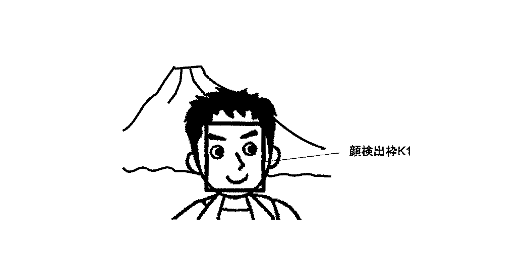
Table 1
ランプの点滅動作と顔検出状態の対応関係は任意に定めることができるが、表1に示す例では以下のような関係に設定されている。
(1)開始ガイド
長い間隔の点滅
顔検出を開始したが、1つも顔を検出していない
(2)右修正ガイド
短・長点滅の繰り返し
1つまたは複数の顔を検出し、顔配置枠に対して顔検出(グループ)枠が右に寄っている。
(3)左修正ガイド
長・短点滅の繰り返し
1つまたは複数の顔を検出し、顔配置枠に対して顔検出(グループ)枠が左に寄っている。
(4)上修正ガイド
長・短・長点滅の繰り返し
1つまたは複数の顔を検出し、顔配置枠に対して顔検出(グループ)枠が上に寄っている。
(5)下修正ガイド
長・短・短点滅の繰り返し
1つまたは複数の顔を検出し、顔配置枠に対して顔検出(グループ)枠が下に寄っている。
(6)修正完了ガイド
短い間隔の点滅
顔検出(グループ)枠が、顔配置枠内に入り、かつ上下方向または左右方向の中央付近にある。
(7)撮影可能ガイド
点灯
顔検出(グループ)枠が、顔配置枠内に入り、かつ上下方向と左右方向共に中央付近にある。
The correspondence between the blinking operation of the lamp and the face detection state can be arbitrarily determined, but in the example shown in Table 1, the following relationship is set.
(1) Start guide Blinking at long intervals Face detection has started, but no face has been detected (2) Right correction guide Repeated short / long blinking Detect one or more faces and place them in the face placement frame On the other hand, the face detection (group) frame is shifted to the right.
(3) Left correction guide Repeated long and short flashing One or more faces are detected, and the face detection (group) frame is shifted to the left with respect to the face arrangement frame.
(4) Upper correction guide Long / Short / Long blinking One or more faces are detected, and the face detection (group) frame is close to the face placement frame.
(5) Lower correction guide Repeated long / short / short flashing One or more faces are detected, and the face detection (group) frame is close to the face placement frame.
(6) Correction completion guide Blinking at short intervals The face detection (group) frame is within the face arrangement frame and is near the center in the vertical direction or the horizontal direction.
(7) Shooting possible guide Lit The face detection (group) frame is within the face arrangement frame and is near the center in both the vertical and horizontal directions.
このガイド表示により、撮影者はデジタルカメラを上下左右いずれかに動かすべき方向を知ることができるので、正確にフレーミングすることができる。画面中央に自身の顔をフレーミングしたいのであれば、AF補助光/セルフタイマランプ4を(6)の状態になるようにカメラを動かしてフレーミングし、撮影を行う。撮影者は、自身の顔を画面の中央ではなく、画面右側や左側で撮影したいかもしれない。本発明の上記実施例による撮影ガイドであれば、意図的に(2)や(3)の状態で撮影することにより、このような要求にも対応することができる。
With this guide display, the photographer can know the direction in which the digital camera should be moved up, down, left, or right, so that framing can be performed accurately. If the user wants to frame his / her face in the center of the screen, the camera moves the AF auxiliary light / self-
撮影者の要求を満たす上記のような撮影ガイドは、ランプの点滅に代えてブザー音で行うようにしてもよい。図11は、ブザー音で撮影ガイドを行う場合のイメージを示す。この実施例にかかるデジタルカメラは、顔検出状態を、図11のようにブザー音を使用し、表2に示すようにブザーによる断続音を変化させて、撮影者の顔検出状態(顔配置枠から撮影者自身の顔がどの位置にあるか)をガイドする。本来、カメラに備えられているブザーは、セルフタイマによる撮影時、メニュー操作時などに動作して、撮影者に注意を喚起するといった本来の用途がある。図示の実施例では、上記のような本来の用途を持っているブザーを、本来の用途とは別に、いわゆる自分撮影などの場合に、顔検出状態の表示用途としても使用している。 The above shooting guide satisfying the photographer's request may be performed with a buzzer sound instead of blinking the lamp. FIG. 11 shows an image when a shooting guide is performed with a buzzer sound. The digital camera according to this embodiment uses a buzzer sound as shown in FIG. 11 and changes the intermittent sound generated by the buzzer as shown in Table 2 to change the face detection state (face arrangement frame). To where the photographer's face is). Originally, a buzzer provided in a camera has an original use such that it operates at the time of photographing by a self-timer, a menu operation, etc., and alerts the photographer. In the illustrated embodiment, the buzzer having the original use as described above is also used as a display application of the face detection state in the case of so-called self-photographing separately from the original use.
表2は、ブザー音と顔検出状態の関係を示している。
表2
Table 2
ブザーの発音動作と顔検出状態の対応関係は任意に定めることができるが、表2に示す例では以下のような関係に設定されている。
(1)開始ガイド
単音の遅い繰り返し
顔検出を開始したが、1つも顔を検出していない
(2)右修正ガイド
短・長音の繰り返し
1つまたは複数の顔を検出し、顔配置枠に対して顔検出(グループ)枠が右に寄っている。
(3)左修正ガイド
長・短音の繰り返し
1つまたは複数の顔を検出し、顔配置枠に対して顔検出(グループ)枠が左に寄っている。
(4)上修正ガイド
長・短・長音の繰り返し
1つまたは複数の顔を検出し、顔配置枠に対して顔検出(グループ)枠が上に寄っている。
(5)下修正ガイド
長・短・短音の繰り返し
1つまたは複数の顔を検出し、顔配置枠に対して顔検出(グループ)枠が下に寄っている。
(6)修正完了ガイド
単音3回
顔検出(グループ)枠が、顔配置枠内に入り、かつ上下方向または左右方向の中央付近にある。
(7)撮影可能ガイド
長音
顔検出(グループ)枠が、顔配置枠内に入り、かつ上下方向と左右方向共に中央付近にある。
The correspondence between the buzzer sounding operation and the face detection state can be determined arbitrarily, but in the example shown in Table 2, the following relationship is set.
(1) Start guide Slow repetition of single sound Face detection has started, but no face has been detected (2) Right correction guide Short / long sound repetition One or more faces are detected and the face placement frame is detected The face detection (group) frame is shifted to the right.
(3) Left Correction Guide Repeating Long / Short One or more faces are detected, and the face detection (group) frame is shifted to the left with respect to the face arrangement frame.
(4) Upper correction guide Repeat of long / short / long sound One or more faces are detected, and the face detection (group) frame is close to the face arrangement frame.
(5) Lower correction guide Repeating long, short, and short sounds One or more faces are detected, and the face detection (group) frame is close to the face arrangement frame.
(6)
(7) Shootable guide long sound The face detection (group) frame is within the face arrangement frame and is near the center in both the vertical and horizontal directions.
表2に示すような、音による撮影ガイドの実施例においても、表1に示すような光による撮影ガイドの実施例と同様に、いわゆる自分撮影の場合などにおいて、撮影者の意図に合致した撮影を行うことができる。表2に示すような、音による撮影ガイドの実施例は、これを単独で実施してもよいし、表1に示すような光による撮影ガイドと組み合わせて実施してもかまわない。 In the embodiment of the shooting guide using sound as shown in Table 2, as in the embodiment of the shooting guide using light as shown in Table 1, shooting that matches the photographer's intention in the case of so-called self-shooting, etc. It can be performed. In the embodiment of the shooting guide by sound as shown in Table 2, this may be carried out alone or in combination with the shooting guide by light as shown in Table 1.
撮影者の要求を満たす上記のような撮影ガイドは、ランプの点滅またはブザー音に代えて音声による言葉を発することで行うようにしてもよい。図12は、音声で撮影ガイドを行う場合のイメージを示す。この実施例では、顔検出状態を、図12に示すように、前記スピーカー7からの音声を利用し、表3に示すように音声を変化させて、撮影者の顔検出状態、すなわち、顔配置枠から撮影者自身の顔がどの位置にあるかをガイドする。
The above-described shooting guide that satisfies the photographer's request may be performed by uttering a voice word instead of blinking a lamp or a buzzer sound. FIG. 12 shows an image when the shooting guide is performed by voice. In this embodiment, as shown in FIG. 12, the face detection state uses the sound from the
表3は、音声ガイドと顔検出状態の関係を示す。
表3
Table 3
表3に示す例では、音声ガイドと顔検出状態の関係が以下のように定められている。
(1)開始ガイド
「自分撮りモードを開始します。」
顔検出を開始したが、1つも顔を検出していない。
(2)右修正ガイド
「カメラを右に向けて下さい。」
1つまたは複数の顔を検出し、顔配置枠に対して顔検出(グループ)枠が右に寄っている。
(3)左修正ガイド
「カメラを左に向けて下さい。」
1つまたは複数の顔を検出し、顔配置枠に対して顔検出(グループ)枠が左に寄っている。
(4)上修正ガイド
「カメラを上に向けて下さい。」
1つまたは複数の顔を検出し、顔配置枠に対して顔検出(グループ)枠が上に寄っている。
(5)下修正ガイド
「カメラを下に向けて下さい。」
1つまたは複数の顔を検出し、顔配置枠に対して顔検出(グループ)枠が下に寄っている。
(6)修正完了ガイド
「止めて下さい。」
顔検出(グループ)枠が、顔配置枠内に入り、かつ上下方向または左右方向の中央付近にある。
(7)撮影可能ガイド
「撮影して下さい。」
顔検出(グループ)枠が、顔配置枠内に入り、かつ上下方向と左右方向共に中央付近にある。
この実施例では、左右方向の撮影位置をガイドし、その後上下方向の撮影位置をガイドするように構成されている。
In the example shown in Table 3, the relationship between the voice guide and the face detection state is defined as follows.
(1) Start Guide “Start selfie mode.”
Face detection has started, but no face has been detected.
(2) Right correction guide “Turn the camera to the right.”
One or more faces are detected, and the face detection (group) frame is shifted to the right with respect to the face arrangement frame.
(3) Left correction guide “Turn the camera to the left.”
One or more faces are detected, and the face detection (group) frame is shifted to the left with respect to the face arrangement frame.
(4) Up Correction Guide “Please turn the camera up.”
One or more faces are detected, and the face detection (group) frame is close to the face arrangement frame.
(5) Lower correction guide "Please point the camera down."
One or more faces are detected, and a face detection (group) frame is positioned below the face arrangement frame.
(6) Correction completion guide "Please stop."
The face detection (group) frame is within the face arrangement frame and is near the center in the vertical direction or the horizontal direction.
(7) Shooting guide “Please shoot.”
The face detection (group) frame is within the face arrangement frame and is near the center in both the vertical and horizontal directions.
In this embodiment, the photographing position in the left-right direction is guided, and then the photographing position in the up-down direction is guided.
図13は、以上説明した音声による撮影ガイドの概念を示す。図13(a)に示すように、実際に写る範囲Mの中央やや右上寄りの位置にある顔検出グループ枠G3を、顔配置枠S7内に位置させるには、カメラの向きを左斜め下方向に向ける必要がある。左右方向のズレを修正するために、「カメラを左に向けて下さい」という音声ガイドを出力する。撮影者は、この音声ガイドに従いカメラの向きを左方向に向ける。左右方方向のズレが修正され、顔配置枠S7内に顔検出グループ枠G3が入ると、「止めて下さい」という音声ガイドを出力する。このガイドに従ってカメラを止めると、図13(b)に示すように左右方向のズレが修正される。続いて、図13(b)に示す状態で、上下方向のズレを修正するために、「カメラを下方向に向けて下さい」という音声ガイドを出力する。撮影者は、この音声ガイドに従いカメラの向きを下方向に向ける。上下方向のズレが修正され、顔配置枠S7内に顔検出グループ枠G3が入ると、「止めて下さい」という音声ガイドを出力する。ガイドに従いカメラを止めると、図13(c)に示すように、上下左右方向のズレが修正された状態で、「撮影して下さい」という音声ガイドを出力する。撮影者は、この音声ガイドに従いシャッタボタン2を押し切り、撮影を行う。
FIG. 13 shows the concept of the above-described audio shooting guide. As shown in FIG. 13 (a), in order to position the face detection group frame G3 located in the center of the range M that is actually captured and slightly to the upper right in the face arrangement frame S7, the camera is directed obliquely downward to the left. It is necessary to turn to. In order to correct the horizontal shift, a voice guide “Please turn the camera to the left” is output. The photographer turns the camera to the left according to the voice guide. When the shift in the left-right direction is corrected and the face detection group frame G3 enters the face arrangement frame S7, a voice guide “Please stop” is output. When the camera is stopped according to this guide, the lateral displacement is corrected as shown in FIG. Subsequently, in the state shown in FIG. 13B, in order to correct the vertical shift, a voice guide “Please turn the camera downward” is output. The photographer turns the camera downward according to the voice guide. When the vertical displacement is corrected and the face detection group frame G3 enters the face arrangement frame S7, a voice guide “Please stop” is output. When the camera is stopped according to the guide, as shown in FIG. 13C, a voice guide “Please take a picture” is output in a state where the vertical and horizontal deviations are corrected. The photographer presses the
図14は、カメラ内部における撮影ガイドの処理手順を示すフローチャートである。ステップS20において、検出した顔位置(顔検出(グループ)枠)が、顔配置枠に属しているかを求め、顔配置枠に属するための修正方向を算出する。次に、ステップS21で、上記算出の結果から左右方向の修正の有無を判定する。左右方向の修正がなければ、ステップS27に進み、左右方向の修正があれば、ステップS22に進む。ステップS22では、その修正方向が、右方向か否かを判定する。修正方向が右方向であれば、ステップS23に進み、修正方向が右方向でなければ、つまり左方向であれば、ステップS24に進む。ステップS23では、右方向のガイドを実行する(表1(2)、表2(2)、表3(2)参照)。撮影者は、このガイドに従ってカメラの向きを修正する。ステップS24では、左方向のガイドを実行する(表1(3)、表2(3)、表3(3)参照)。撮影者は、このガイドに従ってカメラの向きを修正する。この修正により画像中の被写体の左右方向の顔の位置が変化するので、CPU40は、ステップS25で、変化した顔の位置から左右方向のズレが修正されたか否か判定し、修正されたと判定すると、ステップS26に進む。
FIG. 14 is a flowchart showing the processing procedure of the photographing guide inside the camera. In step S20, it is determined whether the detected face position (face detection (group) frame) belongs to the face arrangement frame, and a correction direction for belonging to the face arrangement frame is calculated. Next, in step S21, the presence / absence of correction in the left-right direction is determined from the calculation result. If there is no correction in the left-right direction, the process proceeds to step S27, and if there is a correction in the left-right direction, the process proceeds to step S22. In step S22, it is determined whether or not the correction direction is the right direction. If the correction direction is the right direction, the process proceeds to step S23. If the correction direction is not the right direction, that is, if the correction direction is the left direction, the process proceeds to step S24. In step S23, a right guide is executed (see Table 1 (2), Table 2 (2), and Table 3 (2)). The photographer corrects the direction of the camera according to this guide. In step S24, the left direction guide is executed (see Table 1 (3), Table 2 (3), and Table 3 (3)). The photographer corrects the direction of the camera according to this guide. Since the correction changes the left and right face positions of the subject in the image, the
ステップS26では、ユーザ(撮影者)自身または撮影補助者によるカメラの向きの修正を止めさせるべく、修正完了ガイドを実行する(表1(6)、表2(6)、表3(6)参照)。音声ガイドの場合、「止めて下さい」という音声をスピーカー7から出力する。これにより、被写体の顔の位置の左右方向のズレが修正される。
In step S26, a correction completion guide is executed in order to stop the correction of the camera direction by the user (photographer) himself or a photographing assistant (see Table 1 (6), Table 2 (6), and Table 3 (6)). ). In the case of voice guidance, a voice “Please stop” is output from the
次に、ステップS27で上下方向の修正の有無を判定し、上下方向の修正がなければ、ステップS33に進み、修正が必要であればステップS28に進む。ステップS28では、修正方向が上方向か否かを判定する。修正方向が上方向であればステップS29に進み、上方向でなければ、つまり下方向であれば、ステップS30に進む。ステップS29では、上方向に向けるべき旨のガイドを実行する(表1(4)、表2(4)、表3(4)参照)。音声ガイドの場合、「カメラを上に向けて下さい」という音声をスピーカー7から出力する。ステップS30では、下方向に向けるべき旨のガイドを実行する(表1(5)、表2(5)、表3(5)参照)。音声ガイドの場合、「カメラを下に向けて下さい」という音声をスピーカー7から出力する。撮影者は、この音声ガイドに従ってカメラの向きを修正する。この修正により画像中における被写体の上下方向の顔の位置が変化するので、CPUは、ステップS31において、変化した顔の位置から上下方向のズレが修正されたか否か判定し、修正されたと判定すると、ステップS32に進む。ステップS32では、ユーザによるカメラの向きの修正を止めさせるべく、修正完了ガイドを実行する(表1(6)、表2(6)、表3(6)参照)。音声ガイドの場合、「止めて下さい」という音声をスピーカー7から出力する。このガイドに基づきカメラの移動を停止することにより、被写体の顔の位置の左右方向のズレが修正される。
Next, in step S27, it is determined whether or not there is correction in the vertical direction. If there is no correction in the vertical direction, the process proceeds to step S33, and if correction is required, the process proceeds to step S28. In step S28, it is determined whether the correction direction is upward. If the correction direction is upward, the process proceeds to step S29. If the correction direction is not upward, that is, if it is downward, the process proceeds to step S30. In step S29, a guide indicating that it should be directed upward is executed (see Table 1 (4), Table 2 (4), and Table 3 (4)). In the case of voice guidance, a voice “Please turn the camera upward” is output from the
以上、一連の修正処理により、画像中における被写体の顔の位置が、顔配置枠の中央に位置するので、ステップS33において、撮影可能ガイドを実行する(表1(7)、表2(7)、表3(7)参照)。音声ガイドの場合、「撮影して下さい」という音声をスピーカー7から出力する。これで撮影ガイドの処理を終了する。
As described above, since the position of the subject's face in the image is located at the center of the face arrangement frame by the series of correction processes, the shootable guide is executed in Step S33 (Tables 1 (7) and 2 (7)). Table 3 (7)). In the case of voice guidance, a voice “Please shoot” is output from the
本実施例にかかるデジタルカメラは、図15(b)に示すように、11種類の静止画撮影用シーンモードを持ち、そのうち1つに「自分撮りモード」を備えている。「自分撮りモード」を選択するには、デジタルカメラ本体30のモード切替スイッチ11を「SCENE」に合わせ(図15(a)参照)、↑/MODEボタン15を押す。液晶モニタ9に図15(b)のようなシーン選択画面が表示される。撮影者は、↑/MODEボタン15、→/クイックレビューボタン16、↓/マクロボタン18、←/フラッシュボタン19を使用して、上下左右4方向へカーソルを動かしシーンモードを選択する。MENU/OKボタン17を押すと、シーンモードが決定される。
As shown in FIG. 15B, the digital camera according to the present embodiment has eleven types of still image shooting scene modes, one of which has a “self-portrait mode”. In order to select “selfie mode”, the
「自分撮りモード」では、被写体の顔検出を開始し、人物の顔を検出すると、その人物の顔に対してピント、露出、ホワイトバランスを調整する。同時に、スピーカー7からの音声ガイド(表3)により、被写体の顔が顔配置枠に属するように撮影ガイドをする。この動作を図16に示す。
In the “selfie mode”, detection of the face of the subject is started, and when a person's face is detected, focus, exposure, and white balance are adjusted with respect to the person's face. At the same time, an imaging guide is provided by the voice guide (Table 3) from the
図16において、まず、ステップS40で、「自分撮りモード」の設定有無を判定する。デジタルカメラ本体30のモード切替スイッチ11をSCENEに合わせた後、MODEボタンを押して液晶モニタ9上に表示されるシーンモード選択画面にあるアイコンを、↑↓←→ボタンを押して選択し、MENU/OKボタン17を押し、確定操作を行うことにより「自分撮りモード」を設定する。(図15参照)。次に、ステップS41で、検出開始をユーザへ知らせるために、開始ガイドを実行する(表1(1)、表2(1)、表3(1)参照)。次に、ステップS42で、前記CCD85から得た画像に基づき、顔検出部53で人物の顔位置の検出を行なう。さらに、ステップS43で、顔検出部53の検出結果に基づき、撮影する画像中に人物の顔があるか否か判定する。判定の結果、撮影する画像中に人物の顔がないと判定すると、本処理を終了する。一方、ステップS43で、撮影する画像の中に人物の顔が検出されると、ステップS44に進み、その人物の顔の数に基づいて、顔配置枠設定処理(図9参照)を実行する。続いて、ステップS45で、顔検出(グループ)枠が顔配置枠領域に属しているか否か判定し、その結果に対してガイドを行う撮影ガイド処理(図14参照)を実行する。撮影者は、撮影ガイドにより、被写体すなわち撮影者自身の顔またはグループを構成する人物の顔が望んだ位置(画面中央、画面右側など)にあると判断したら、シャッタボタン2を押し切り撮影を行えば良い。
In FIG. 16, first, in step S40, it is determined whether or not the “selfie mode” is set. After setting the
ここまで説明してきた実施例にかかるデジタルカメラは、撮影者自らが手持ちで撮影を行い、撮影したいタイミングでシャッタボタン2を押し切り撮影を行うことが前提である。この場合、ミニ三脚や一脚などをカメラの三脚ネジ穴15へ取り付けて、その三脚の”脚”を手で持ち、シャッタボタン2に指がかからない状態での撮影スタイルには対応できない。そこで、本発明の別の実施例では、セルフタイマの機能の1つとして「自分撮り2秒モード」を用意する。図17は、セルフタイマボタンの操作により、本来のセルフタイマとしての機能と自分撮り機能とを選択するイメージを示す。カメラ本体30に設けられている削除/セルフタイマボタン14は、1回押すごとに、10秒(図17(b))→2秒(図17(c))→自分撮り2秒(図17(d))→セルフタイマ解除(図17(a))・・・と順に切り替わる。自分撮り2秒に設定してシャッタボタン2を押し切ると、ピントが固定され、撮影ガイドを行い、撮影ガイドが終了するとAF補助光/セルフタイマランプ4が2秒間点滅して撮影される。図18はこの撮影モードでの撮影ガイドを示す。
The digital camera according to the embodiment described so far is based on the premise that the photographer himself takes a picture and holds the
まず、ステップS50で「自分撮り2秒モード」の設定有無を判定する。「自分撮り2秒モード」に設定されていれば、次に、ステップS51で、シャッタボタン2を押し切ったか否かを判定する。シャッタボタン2を押し切っていれば、ピントを70〜80cmに固定する。続いて、ステップS52で、検出開始をユーザへ知らせるために、開始ガイドを実行する(表1(1)、表2(1)、表3(1)参照)。ステップS53で、CCD85から得た画像データに基づき、顔検出部53で人物の顔位置の検出を行なう。ステップS54で、顔検出部53の検出結果に基づき、撮影する画像中に人物の顔があるか判定する。判定の結果、撮影する画像中に人物の顔がないと判定すると、ステップS59に進み、「自分撮り2秒モード」撮影機能の終了指示の有無を判定する。
First, in step S50, it is determined whether or not the “self-portrait 2-second mode” is set. If the “self-portrait 2-second mode” is set, it is then determined in step S51 whether or not the
一方、ステップS54で、撮影する画像の中に人物の顔が検出されると、ステップS55で、ピント、露出、ホワイトバランスを調整し、その人物の顔の数に基づいて、顔配置枠設定処理(図9参照)を実行する。次に、ステップS56で、顔検出(グループ)枠が顔配置枠領域に属しているか判定し、その結果に対してガイドを行う撮影ガイド処理(図14参照)を実行する。次に、ステップS57で、撮影ガイド処理の結果、音声ガイドの場合、「撮影して下さい」という音声がスピーカー7から出力されなければ、ステップS59に進み、「自分撮り2秒モード」撮影機能の終了指示の有無を判定する。検出された顔の位置が、顔配置枠に属していると判定すると、ステップS58で、AF補助光/セルフタイマランプ4を2秒間点滅した後、自動的に撮影を実行し、撮影した画像をカードに記録する。この後、ステップS59で「自分撮り2秒モード」撮影機能の終了指示の有無を判定し、終了指示がないと判定すると、ステップS53に戻り、再度、人物の顔位置の検出が行なわれる。一方、終了指示ありと判定すると、「自分撮り2秒モード」撮影機能を終了する。
このように、「自分撮り2秒モード」撮影機能による自動撮影を行えば、撮影者自身を顔配置枠に属するように配置した構図の画像を自動で撮影することができる。
On the other hand, when a human face is detected in the image to be photographed in step S54, the focus, exposure, and white balance are adjusted in step S55, and face arrangement frame setting processing is performed based on the number of the human faces. (See FIG. 9). Next, in step S56, it is determined whether or not the face detection (group) frame belongs to the face arrangement frame region, and an imaging guide process (see FIG. 14) is performed to guide the result. Next, in step S57, if the result of the shooting guide processing is a voice guide, if the voice “Please shoot” is not output from the
In this way, if automatic shooting is performed using the “self-portrait 2-second mode” shooting function, an image of a composition in which the photographer himself is placed so as to belong to the face placement frame can be automatically shot.
以上、いずれの実施例にかかるデジタルカメラであっても、顔検出(グループ)枠を、あらかじめ設定した顔配置枠に属するようにガイドすることで、撮影者の意図した構図での画像を撮影することができることを示した。しかし、撮影者の腕の長さや顔の大きさは、人により多少異なってくる。そこで、次に説明する実施例では、この問題に対応するために、焦点距離を変更することにより、画面内の人物が占める割合が適切となるようにしている。図19に、この実施例の動作を示す。 As described above, in any of the digital cameras according to any of the embodiments, the face detection (group) frame is guided so as to belong to the preset face arrangement frame, thereby capturing an image with the composition intended by the photographer. Showed that it can. However, the length of the photographer's arm and the size of the face vary somewhat from person to person. Therefore, in the embodiment described below, in order to cope with this problem, the ratio of the person in the screen is made appropriate by changing the focal length. FIG. 19 shows the operation of this embodiment.
図19において、まず、ステップS60で、「自分撮りモード」の設定有無を判定する。撮影者は、デジタルカメラ本体30のモード切替スイッチ11をSCENEに合わせた後、MODEボタンを押して液晶モニタ9上に表示されるシーンモード選択画面にあるアイコンを、↑↓←→ボタンを押して選択し、MENU/OKボタン17を押し、確定操作を行うことにより「自分撮りモード」を設定する。(図15参照)。次のステップS61では、検出開始をユーザへ知らせるために、CPU40は、開始ガイドを実行する(表1(1)、表2(1)、表3(1)参照)。次のステップS62で、CPU40は、CCD85から得た画像に基づき、顔検出部53で人物の顔位置の検出を行なう。ステップS63で、CPU40は、顔検出部53の検出結果に基づき、撮影する画像中に人物の顔があるか判定する。判定の結果、撮影する画像中に人物の顔がないと判定すると、本処理を終了する。
In FIG. 19, first, in step S60, it is determined whether or not the “selfie mode” is set. The photographer sets the
一方、ステップS63で、撮影する画像の中に人物の顔が検出されると、ステップS64で、CPU40は、その人物の顔の数に基づいて、顔配置枠設定処理(図9参照)を実行する。次のステップS65で、CPU40は、顔検出(グループ)枠と顔配置枠の面積を比較し、後述する焦点距離設定処理を実行する。さらに、ステップS66で、CPU40は、顔検出(グループ)枠が顔配置枠領域に属しているか判定し、その結果に対してガイドを行う撮影ガイド処理(図14参照)を実行する。撮影者は、撮影ガイドにより、被写体が望んだ位置(画面中央、画面右側など)にあると判断したら、シャッタボタン2を押し切り撮影を行う。
On the other hand, when a human face is detected in the image to be photographed in step S63, the
画面内の人物が占める割合が適切となるように、焦点距離を変更すると先に述べた。図20は、この焦点距離設定の概念図である。図20(a)では、35mmサイズのフイルム対応カメラに換算して40mmの焦点距離で自分撮りを実施した場合の例を示している。この場合、顔検出枠K12の面積KA12=(K12(x3)−K12(x1))×(K12(y2)−K12(y1))と顔配置枠S5の面積SA5=(S5(x3)−S5(x1))×(S5(y2)−S5(y1))がほぼ等しいため、画面内の人物の顔が占める割合が大きくなり、背景の割合が小さくなってしまい、画面内に占める人物の顔の割合が適切であるとは言い難い。そこで、図20(b)のように、焦点距離を35mmサイズのカメラ換算で28mmの焦点距離に変更し、顔検出枠をK12からK13とする。これにより、画面内の人物の顔が占める割合が小さくなり、画面内に占める人物の顔の割合が適切となる。 I mentioned earlier that the focal length is changed so that the proportion of people in the screen is appropriate. FIG. 20 is a conceptual diagram of this focal length setting. FIG. 20A shows an example of a case where a self-portrait is performed at a focal length of 40 mm in terms of a 35 mm film compatible camera. In this case, the area KA12 of the face detection frame K12 = (K12 (x3) −K12 (x1)) × (K12 (y2) −K12 (y1)) and the area SA5 of the face placement frame S5 = (S5 (x3) −S5). Since (x1)) × (S5 (y2) −S5 (y1)) is substantially equal, the ratio of the person's face in the screen increases, the ratio of the background decreases, and the person's face in the screen Is not appropriate. Therefore, as shown in FIG. 20B, the focal length is changed to a focal length of 28 mm in terms of a 35 mm size camera, and the face detection frame is changed from K12 to K13. As a result, the proportion of the person's face in the screen is reduced, and the proportion of the person's face in the screen is appropriate.
図21は、このような焦点距離変更動作を示す。ステップS70において、CPU40は、現在設定されている顔配置枠S9の面積SA9を算出する。図20(a)に示す例の場合、設定されている顔配置枠S9はS5で、S5の面積SA5がSA9と等しくなる。次のステップS71で、CPU40は、顔配置枠の面積SA9より上限閾値L1、および下限閾値L2を算出する。L1およびL2は前記フラッシュROM58に格納されている固定値であり、面積SA9が決まると自動的にL1およびL2が決定される。例えばL1=SA5×0.8、L2=SA5×0.2とする。次のステップS72で、CPU40は、顔検出(グループ)枠G4の面積GA4を算出する。図20(a)に示す例の場合、検出している人物の顔は1つなので、顔検出グループ枠=顔検出枠K12となり、K12の面積KA12がG4と等しくなる。
FIG. 21 shows such a focal length changing operation. In step S70, the
次のステップS73で、CPU40は、GA4とL1の値を比較し、GA4がL1より大きければステップS74へ進み、そうでなければステップS75へ進む。ステップS74で、CPU40は、GA4とL2の値を比較し、GA4がL2より小さければ焦点距離設定処理を終了する。ステップS75では、GA4がL1より小さい場合、画面に占める人物の顔の割合が大きすぎると判断し、ズームレンズを広角側へ移動させ、焦点距離が小さくなるようにする。例えば図20(a)から図20(b)のように35mm換算で40mmから28mmへ変更する。次に、ステップS76で撮影ガイドを実施する。音声ガイドの場合、「広角側にズームします」という音声をスピーカー7から出力する。
In the next step S73, the
次に、ステップS77で、GA4がL2より小さい場合、画面に占める人物の顔の割合が小さすぎると判断し、ズームレンズを望遠側へ移動させ、焦点距離が大きくなるようにする。例えば図20(b)から図20(a)のように35mm換算で28mmから40mmへ変更する。次に、ステップS78で撮影ガイドを実施する。音声ガイドの場合、「望遠側にズームします」という音声をスピーカー7から出力する。
In step S77, if GA4 is smaller than L2, it is determined that the ratio of the person's face in the screen is too small, and the zoom lens is moved to the telephoto side so that the focal length is increased. For example, as shown in FIG. 20B to FIG. 20A, it is changed from 28 mm to 40 mm in terms of 35 mm. Next, an imaging guide is implemented in step S78. In the case of voice guidance, a voice “zoom to the telephoto side” is output from the
本実施例では、ステップS75およびステップS77にて、デジタルカメラ30が自動的に焦点距離を変更するよう構成しているが、ステップS75およびステップS77を省略し、ステップS76およびステップS78の音声ガイドにて撮影者にズーム操作を行ってもらうように撮影ガイドを行う。例えば「広角側にズームしてください」、「望遠側にズームしてください」としてもよい。
撮影ガイドは、以上説明したように光、音、音声により行うようにしてもよいし、振動モータ、バイブレータなどを用いて、振動によって行うようにしてもよい。
本発明によれば、いわゆる「自分撮りモード」で撮影する場合に限らず、第三者に撮影操作を依頼してカメラユーザー自身を撮影してもらう場合であっても、カメラユーザーが意図している構図に誘導し撮影することが可能である。
In this embodiment, the
As described above, the photographing guide may be performed by light, sound, or sound, or may be performed by vibration using a vibration motor, a vibrator, or the like.
According to the present invention, the camera user intends not only to shoot in the so-called “selfie mode” but also to request a shooting operation by a third party to photograph the camera user himself. It is possible to guide and shoot in a composition.
6 マイク
7 スピーカー
9 液晶モニタ
30 カメラ本体
40 CPU
41 操作部
53 顔検出部
54 メモリ
58 フラッシュROM
84 CCD
6
41
84 CCD
Claims (16)
固体撮影素子面に結像する撮影画像の中から人物の顔の位置を検出する顔検出手段と、
画像内の所定位置に所定サイズで、前記顔検出手段で検出された人物の顔を配置する領域を設定する顔配置領域設定手段と、
前記顔検出手段で検出された人物の顔の位置が、前記顔配置設定手段により設定された顔配置領域内に位置するように案内するガイド手段と、を備えていることを特徴とする撮像装置。 In an imaging device that captures an image using a solid-state imaging device,
Face detection means for detecting the position of a person's face from a captured image formed on a solid imaging element surface;
Face arrangement area setting means for setting an area in which a face of a person detected by the face detection means is arranged at a predetermined size in a predetermined position in an image;
An image pickup apparatus comprising: guide means for guiding the face position of the person detected by the face detection means to be located within the face placement area set by the face placement setting means. .
固体撮影素子面に結像する撮影画像の中から人物の顔の位置を検出する顔検出プロセスと、
画像内の所定位置に所定サイズで、前記顔検出手段で検出された人物の顔を配置する領域を設定する顔配置領域設定プロセスと、
前記顔検出手段で検出された人物の顔の位置が、前記顔配置設定手段により設定された顔配置領域内に位置するように案内するガイドプロセスと、を備えていることを特徴とする撮像方法。 In an imaging method for imaging an image using a solid-state imaging device,
A face detection process for detecting the position of a person's face from a photographed image formed on a solid-state image sensor surface;
A face arrangement area setting process for setting an area in which a face of a person detected by the face detection means is arranged at a predetermined size in a predetermined position in an image;
A guide process for guiding the position of the face of the person detected by the face detecting means to be located within the face placement area set by the face placement setting means. .
Priority Applications (1)
| Application Number | Priority Date | Filing Date | Title |
|---|---|---|---|
| JP2007233541A JP2009065577A (en) | 2007-09-10 | 2007-09-10 | Imaging apparatus and imaging method |
Applications Claiming Priority (1)
| Application Number | Priority Date | Filing Date | Title |
|---|---|---|---|
| JP2007233541A JP2009065577A (en) | 2007-09-10 | 2007-09-10 | Imaging apparatus and imaging method |
Publications (1)
| Publication Number | Publication Date |
|---|---|
| JP2009065577A true JP2009065577A (en) | 2009-03-26 |
Family
ID=40559726
Family Applications (1)
| Application Number | Title | Priority Date | Filing Date |
|---|---|---|---|
| JP2007233541A Pending JP2009065577A (en) | 2007-09-10 | 2007-09-10 | Imaging apparatus and imaging method |
Country Status (1)
| Country | Link |
|---|---|
| JP (1) | JP2009065577A (en) |
Cited By (20)
| Publication number | Priority date | Publication date | Assignee | Title |
|---|---|---|---|---|
| JP2010278624A (en) * | 2009-05-27 | 2010-12-09 | Sony Corp | Imaging apparatus and method, and program |
| US20110050976A1 (en) * | 2009-08-26 | 2011-03-03 | Samsung Electronics Co. Ltd. | Photographing method and system |
| JP2011066583A (en) * | 2009-09-16 | 2011-03-31 | Olympus Imaging Corp | Photographing device and control method for the same |
| WO2011038785A1 (en) * | 2009-10-02 | 2011-04-07 | Sony Ericsson Mobile Communications Ab | Portrait photo assistant |
| JP2012129699A (en) * | 2010-12-14 | 2012-07-05 | Denso Corp | Face photographing system |
| CN102739934A (en) * | 2011-03-31 | 2012-10-17 | 索尼公司 | Image processing apparatus, image processing method, image processing program, and imaging apparatus |
| JP2012253551A (en) * | 2011-06-02 | 2012-12-20 | Sony Corp | Display control apparatus, display control method, and program |
| WO2012176441A1 (en) * | 2011-06-23 | 2012-12-27 | 株式会社ニコン | Imaging device |
| JP2013009106A (en) * | 2011-06-23 | 2013-01-10 | Nikon Corp | Imaging apparatus |
| JP2013526099A (en) * | 2010-03-03 | 2013-06-20 | インテレクチュアル ベンチャーズ ファンド 83 エルエルシー | Imaging device for taking self-portrait images |
| JP2014506026A (en) * | 2010-11-29 | 2014-03-06 | デジタルオプティックス・コーポレイション・ヨーロッパ・リミテッド | Portrait image synthesis from multiple images captured by a portable device |
| KR20140105313A (en) * | 2013-02-22 | 2014-09-01 | 삼성전자주식회사 | Apparatus and method for shooting an image in a device having a camera |
| US9282239B2 (en) | 2013-01-04 | 2016-03-08 | Samsung Electronics Co., Ltd. | Apparatus and method for photographing portrait in portable terminal having camera |
| KR101605420B1 (en) | 2009-12-03 | 2016-03-22 | 삼성전자주식회사 | A digital photographing apparatus and a method for controlling the same |
| JP2017055182A (en) * | 2015-09-07 | 2017-03-16 | オムロン株式会社 | Imaging apparatus, imaging method, and imaging program |
| JP2017076062A (en) * | 2015-10-15 | 2017-04-20 | キヤノン株式会社 | Imaging apparatus, control method and program |
| JP2017518691A (en) * | 2014-05-13 | 2017-07-06 | クアルコム,インコーポレイテッド | System and method for providing haptic feedback to assist in image capture |
| KR101825321B1 (en) * | 2017-02-03 | 2018-02-02 | 한양대학교 산학협력단 | System and method for providing feedback of real-time optimal shooting composition using mobile camera recognition technology |
| WO2018207287A1 (en) * | 2017-05-10 | 2018-11-15 | 三菱電機株式会社 | Image capture assist device and image capture assist method |
| JP2022139871A (en) * | 2021-03-12 | 2022-09-26 | 大日本印刷株式会社 | shooting system |
-
2007
- 2007-09-10 JP JP2007233541A patent/JP2009065577A/en active Pending
Cited By (34)
| Publication number | Priority date | Publication date | Assignee | Title |
|---|---|---|---|---|
| JP2010278624A (en) * | 2009-05-27 | 2010-12-09 | Sony Corp | Imaging apparatus and method, and program |
| US8451363B2 (en) * | 2009-08-26 | 2013-05-28 | Samsung Electronics Co., Ltd. | Photographing method and system |
| US20110050976A1 (en) * | 2009-08-26 | 2011-03-03 | Samsung Electronics Co. Ltd. | Photographing method and system |
| JP2011066583A (en) * | 2009-09-16 | 2011-03-31 | Olympus Imaging Corp | Photographing device and control method for the same |
| US8675082B2 (en) | 2009-09-16 | 2014-03-18 | Olympus Imaging Corp. | Imaging device and imaging device control method |
| WO2011038785A1 (en) * | 2009-10-02 | 2011-04-07 | Sony Ericsson Mobile Communications Ab | Portrait photo assistant |
| KR101605420B1 (en) | 2009-12-03 | 2016-03-22 | 삼성전자주식회사 | A digital photographing apparatus and a method for controlling the same |
| US9462181B2 (en) | 2010-03-03 | 2016-10-04 | Intellectual Ventures Fund 83 Llc | Imaging device for capturing self-portrait images |
| JP2013526099A (en) * | 2010-03-03 | 2013-06-20 | インテレクチュアル ベンチャーズ ファンド 83 エルエルシー | Imaging device for taking self-portrait images |
| US9118833B2 (en) | 2010-11-29 | 2015-08-25 | Fotonation Limited | Portrait image synthesis from multiple images captured on a handheld device |
| JP2014506026A (en) * | 2010-11-29 | 2014-03-06 | デジタルオプティックス・コーポレイション・ヨーロッパ・リミテッド | Portrait image synthesis from multiple images captured by a portable device |
| US10110804B2 (en) | 2010-11-29 | 2018-10-23 | Fotonation Limited | Portrait image synthesis from multiple images captured on a handheld device |
| KR101845318B1 (en) * | 2010-11-29 | 2018-05-18 | 포토내이션 리미티드 | Portrait image synthesis from multiple images captured on a handheld device |
| US9456128B2 (en) | 2010-11-29 | 2016-09-27 | Fotonation Limited | Portrait image synthesis from multiple images captured on a handheld device |
| JP2012129699A (en) * | 2010-12-14 | 2012-07-05 | Denso Corp | Face photographing system |
| JP2012217132A (en) * | 2011-03-31 | 2012-11-08 | Sony Corp | Image processing apparatus, image processing method, image processing program, and imaging apparatus |
| CN102739934A (en) * | 2011-03-31 | 2012-10-17 | 索尼公司 | Image processing apparatus, image processing method, image processing program, and imaging apparatus |
| CN102739934B (en) * | 2011-03-31 | 2017-03-01 | 索尼公司 | Image processing apparatus, image processing method, image processing program and imaging device |
| JP2012253551A (en) * | 2011-06-02 | 2012-12-20 | Sony Corp | Display control apparatus, display control method, and program |
| JP2013009106A (en) * | 2011-06-23 | 2013-01-10 | Nikon Corp | Imaging apparatus |
| WO2012176441A1 (en) * | 2011-06-23 | 2012-12-27 | 株式会社ニコン | Imaging device |
| US9282239B2 (en) | 2013-01-04 | 2016-03-08 | Samsung Electronics Co., Ltd. | Apparatus and method for photographing portrait in portable terminal having camera |
| KR20140105313A (en) * | 2013-02-22 | 2014-09-01 | 삼성전자주식회사 | Apparatus and method for shooting an image in a device having a camera |
| KR102093647B1 (en) * | 2013-02-22 | 2020-03-26 | 삼성전자 주식회사 | Apparatus and method for shooting an image in a device having a camera |
| JP2017518691A (en) * | 2014-05-13 | 2017-07-06 | クアルコム,インコーポレイテッド | System and method for providing haptic feedback to assist in image capture |
| JP2017055182A (en) * | 2015-09-07 | 2017-03-16 | オムロン株式会社 | Imaging apparatus, imaging method, and imaging program |
| JP2017076062A (en) * | 2015-10-15 | 2017-04-20 | キヤノン株式会社 | Imaging apparatus, control method and program |
| KR101825321B1 (en) * | 2017-02-03 | 2018-02-02 | 한양대학교 산학협력단 | System and method for providing feedback of real-time optimal shooting composition using mobile camera recognition technology |
| WO2018207287A1 (en) * | 2017-05-10 | 2018-11-15 | 三菱電機株式会社 | Image capture assist device and image capture assist method |
| JPWO2018207287A1 (en) * | 2017-05-10 | 2019-11-07 | 三菱電機株式会社 | Imaging assistance device and imaging assistance method |
| CN110651465A (en) * | 2017-05-10 | 2020-01-03 | 三菱电机株式会社 | Shooting assistance device and shooting assistance method |
| CN110651465B (en) * | 2017-05-10 | 2021-02-05 | 三菱电机株式会社 | Shooting assistance device and shooting assistance method |
| US11070719B2 (en) * | 2017-05-10 | 2021-07-20 | Mitsubishi Electric Corporation | Image capture assist device and image capture assist method |
| JP2022139871A (en) * | 2021-03-12 | 2022-09-26 | 大日本印刷株式会社 | shooting system |
Similar Documents
| Publication | Publication Date | Title |
|---|---|---|
| JP2009065577A (en) | Imaging apparatus and imaging method | |
| JP4135100B2 (en) | Imaging device | |
| JP4904108B2 (en) | Imaging apparatus and image display control method | |
| US7973848B2 (en) | Method and apparatus for providing composition information in digital image processing device | |
| JP4761146B2 (en) | Imaging apparatus and program thereof | |
| JP4787180B2 (en) | Imaging apparatus and imaging method | |
| JP4644883B2 (en) | Imaging device | |
| JP2005128437A (en) | Photographing device | |
| JP4730667B2 (en) | Automatic regeneration method and apparatus | |
| JP4799501B2 (en) | Image capturing apparatus, image capturing apparatus control method, and program | |
| JP2009058834A (en) | Imaging device | |
| JP4730553B2 (en) | Imaging apparatus and exposure control method | |
| JP2006145629A (en) | Imaging apparatus | |
| JP2007324877A (en) | Imaging device | |
| JP2012019341A (en) | Imaging device, and method and program for controlling the same | |
| JP5429588B2 (en) | Imaging apparatus and imaging method | |
| JP2010141609A (en) | Imaging apparatus | |
| JP2008028728A (en) | Digital camera | |
| JP4697549B2 (en) | Image capturing apparatus and face detection method thereof | |
| JP4964992B2 (en) | Image capturing apparatus and image recording method thereof | |
| JP2009077266A (en) | Digital camera and digital camera focus area selection method | |
| JP4697461B2 (en) | Imaging device | |
| JP3395769B2 (en) | Digital still camera | |
| JP4761039B2 (en) | Imaging device | |
| JP2008035243A (en) | Imaging device |