JP2008233683A - Cryptographic processing apparatus and program - Google Patents
Cryptographic processing apparatus and program Download PDFInfo
- Publication number
- JP2008233683A JP2008233683A JP2007075452A JP2007075452A JP2008233683A JP 2008233683 A JP2008233683 A JP 2008233683A JP 2007075452 A JP2007075452 A JP 2007075452A JP 2007075452 A JP2007075452 A JP 2007075452A JP 2008233683 A JP2008233683 A JP 2008233683A
- Authority
- JP
- Japan
- Prior art keywords
- mask
- state
- column
- value
- states
- Prior art date
- Legal status (The legal status is an assumption and is not a legal conclusion. Google has not performed a legal analysis and makes no representation as to the accuracy of the status listed.)
- Withdrawn
Links
Images


Classifications
-
- H—ELECTRICITY
- H04—ELECTRIC COMMUNICATION TECHNIQUE
- H04L—TRANSMISSION OF DIGITAL INFORMATION, e.g. TELEGRAPHIC COMMUNICATION
- H04L9/00—Cryptographic mechanisms or cryptographic arrangements for secret or secure communications; Network security protocols
- H04L9/06—Cryptographic mechanisms or cryptographic arrangements for secret or secure communications; Network security protocols the encryption apparatus using shift registers or memories for block-wise or stream coding, e.g. DES systems or RC4; Hash functions; Pseudorandom sequence generators
- H04L9/0618—Block ciphers, i.e. encrypting groups of characters of a plain text message using fixed encryption transformation
-
- H—ELECTRICITY
- H04—ELECTRIC COMMUNICATION TECHNIQUE
- H04L—TRANSMISSION OF DIGITAL INFORMATION, e.g. TELEGRAPHIC COMMUNICATION
- H04L9/00—Cryptographic mechanisms or cryptographic arrangements for secret or secure communications; Network security protocols
- H04L9/002—Countermeasures against attacks on cryptographic mechanisms
-
- H—ELECTRICITY
- H04—ELECTRIC COMMUNICATION TECHNIQUE
- H04L—TRANSMISSION OF DIGITAL INFORMATION, e.g. TELEGRAPHIC COMMUNICATION
- H04L2209/00—Additional information or applications relating to cryptographic mechanisms or cryptographic arrangements for secret or secure communication H04L9/00
- H04L2209/04—Masking or blinding
- H04L2209/046—Masking or blinding of operations, operands or results of the operations
-
- H—ELECTRICITY
- H04—ELECTRIC COMMUNICATION TECHNIQUE
- H04L—TRANSMISSION OF DIGITAL INFORMATION, e.g. TELEGRAPHIC COMMUNICATION
- H04L2209/00—Additional information or applications relating to cryptographic mechanisms or cryptographic arrangements for secret or secure communication H04L9/00
- H04L2209/24—Key scheduling, i.e. generating round keys or sub-keys for block encryption
Landscapes
- Engineering & Computer Science (AREA)
- Computer Security & Cryptography (AREA)
- Computer Networks & Wireless Communication (AREA)
- Signal Processing (AREA)
Abstract
【課題】ラウンド鍵配列へのマスク値が0になることを阻止し、且つマスク管理の複雑化を低減させる。
【解決手段】7種類のマスク状態から、Sボックス入力保護マスク、Sボックス出力保護マスク、ラウンド鍵保護マスクの1列目のマスク状態を選択し、Sボックス出力保護マスクのマスク状態、1列目のマスク状態、及び「当該Sボックス出力保護マスクのマスク状態と当該1列目のマスク状態との排他的論理和の演算結果」とは異なるマスク状態を、ラウンド鍵保護マスクの2列目のマスク状態として選択し、3列目と4列目のマスク状態を選択し、ラウンド鍵更新後の1列目から4列目までのマスク状態を計算し、このマスク状態に禁止状態“000”が含まれないとき、選択された各マスク状態に対応して各基本マスク値同士を排他的論理和し、各マスク状態に対応する合成マスク値を計算する。
【選択図】 図5An object of the present invention is to prevent a mask value for a round key arrangement from becoming zero and reduce the complexity of mask management.
The mask state of the first column of the S box input protection mask, the S box output protection mask, and the round key protection mask is selected from seven types of mask states, and the mask state of the S box output protection mask and the first column are selected. And the mask state of the second column of the round key protection mask different from the “masked state of the S box output protection mask and the result of the exclusive OR of the mask state of the first column”. Select the state, select the mask states of the third and fourth columns, calculate the mask states from the first column to the fourth column after updating the round key, and this mask state includes the prohibited state “000” If not, the basic mask values are exclusively ORed with each selected mask state to calculate a combined mask value corresponding to each mask state.
[Selection] Figure 5
Description
本発明は、暗号処理装置及びプログラムに係り、例えば電力解析による解読に対する耐性を向上し得る暗号処理装置及びプログラムに関する。 The present invention relates to a cryptographic processing apparatus and program, and more particularly to a cryptographic processing apparatus and program that can improve resistance to decryption by power analysis.
一般に、データの暗号化や認証などの暗号処理を実行するコンピュータとしては、パーソナルコンピュータが広く知られており、他には、スマートカードあるいはICカードと呼ばれ、ICモジュールを搭載したカード形状のデバイスが知られている。 In general, a personal computer is widely known as a computer that performs encryption processing such as data encryption and authentication, and is also called a smart card or IC card, and is a card-shaped device equipped with an IC module. It has been known.
この種の暗号処理には、DES(data encryption standard)及びトリプル(triple)DES(例えば、非特許文献1参照。)や、非特許文献2に挙げられるAES(advance encryption standard)(例えば、非特許文献2参照。)などの共通鍵暗号アルゴリズムや、任意の公開鍵暗号アルゴリズムが用いられる。 For this type of encryption processing, DES (data encryption standard) and triple DES (for example, see Non-Patent Document 1) and AES (advance encryption standard) listed in Non-Patent Document 2 (for example, non-patent) A common key encryption algorithm such as Reference 2) or an arbitrary public key encryption algorithm is used.
これらの暗号技術に対する暗号解読の方法として、暗号文等の入手可能な情報から、平文や秘密鍵等の秘密情報を回復する技術がある。係る暗号解読の技術では、秘密鍵の回復が可能であるか否かが安全性評価の指標としてよく用いられる。暗号解読に用いる情報としては、暗号文等の入手可能な情報に限らず、特定したい秘密鍵とは値が異なる鍵を用いた情報も使用可能である。すなわち、重要な秘密鍵の値を特定するため、ユーザが任意の鍵の組み合わせで暗号処理装置を使用し、得られた情報から目的の秘密鍵を特定するという解読手法も考えられる。 As a decryption method for these encryption techniques, there is a technique for recovering secret information such as plaintext and secret key from available information such as ciphertext. In such cryptanalysis technology, whether or not the secret key can be recovered is often used as an index for security evaluation. Information used for decryption is not limited to information that can be obtained, such as ciphertext, but information using a key whose value is different from the secret key to be specified can also be used. In other words, in order to specify an important secret key value, a decryption technique is also conceivable in which a user uses a cryptographic processing device with an arbitrary combination of keys and specifies a target secret key from the obtained information.
この解読手法の一例としては、電力解析攻撃が知られている(例えば、非特許文献3参照。)。電力解析攻撃は、パーソナルコンピュータ又はICカード等のデバイスに搭載された暗号処理装置のハードウェア又はソフトウェアが暗号処理の内容と消費電力との間に相関を持つことに着目し、観測した消費電力の情報から内部の秘密鍵や平文に関する情報を推定する手法である。電力解析には、単純電力解析(以下、SPAという)と差分電力解析(以下、DPAという)が含まれる。SPAは暗号処理の電力消費の特徴を抽出して解読に役立てる方法であり、DPAはデータ毎に僅かに異なる暗号処理中の消費電力間の差分や相関を利用して解読する方法である。 As an example of this decoding technique, a power analysis attack is known (for example, see Non-Patent Document 3). The power analysis attack focuses on the fact that the hardware or software of the cryptographic processing device installed in a device such as a personal computer or IC card has a correlation between the content of the cryptographic processing and the power consumption. This is a method for estimating internal secret key and plaintext information from information. The power analysis includes simple power analysis (hereinafter referred to as SPA) and differential power analysis (hereinafter referred to as DPA). SPA is a method for extracting the characteristics of power consumption of cryptographic processing and using it for decryption, and DPA is a method for decrypting by using a difference or correlation between power consumption during cryptographic processing slightly different for each data.
従来の電力解析への対策法としては、ノイズ発生器により暗号処理の電力消費量の測定を撹乱し、測定精度を悪化させる方法や、トランジスタや配線の改良により処理に関する電力消費の変動を測定困難なレベルに抑える方法や、暗号アルゴリズムの実装に対策を施し電力解析による解読を困難にする方法などが提案されている。 Conventional countermeasures for power analysis include a method of disturbing the measurement of power consumption for cryptographic processing with a noise generator and degrading measurement accuracy, and a difficulty in measuring fluctuations in power consumption related to processing by improving transistors and wiring Proposals have been made to reduce the level to a certain level and to make the decryption difficult by power analysis by taking measures to implement the cryptographic algorithm.
暗号アルゴリズムの実装に対策を施した手法としては、いわゆるマスキング法が広く知られている(例えば非特許文献4参照。)。マスキング法とは、処理内容と消費電力との相関を利用する電力解析の原理に着目し、処理するデータにマスクと呼ばれる乱数Rを適用し、消費電力を擾乱して解析を困難にする方法である。具体的には、暗号処理装置は、内部データDに乱数Rを排他的論理和演算(XOR)して得られた内部データD’=D xor Rを暗号処理することにより、消費電力を擾乱する。また、Sボックス(以下、S-boxともいう)と呼ばれる非線形置換においては、入力と出力にそれぞれマスクを適用して変形された置換テーブルが用いられる。 A so-called masking method is widely known as a method for taking measures against the implementation of a cryptographic algorithm (for example, see Non-Patent Document 4). The masking method focuses on the principle of power analysis that uses the correlation between processing content and power consumption, and applies a random number R called a mask to the data to be processed, thus disturbing power consumption and making analysis difficult. is there. Specifically, the cryptographic processing apparatus disturbs power consumption by cryptographically processing internal data D ′ = D xor R obtained by exclusive OR (XOR) the random number R with the internal data D. . Further, in non-linear replacement called S box (hereinafter also referred to as S-box), a replacement table modified by applying a mask to input and output is used.
なお、マスキング法は、マスクによる方法に限らず、例えば加減算による手法や、内部データに冗長な表現を用い、一部のビットを乱数で置換して暗号処理と消費電力との相関を撹乱する手法などもある。 Note that the masking method is not limited to the mask method, for example, a method using addition / subtraction, or a method that uses redundant expressions for internal data and replaces some bits with random numbers to disturb the correlation between encryption processing and power consumption. There are also.
また、暗号解読の分野では、消費電力を観測する電力解析攻撃を含む概念として、消費電力等の暗号処理に関する情報を観測する攻撃方法を総称してサイドチャネル攻撃と呼ぶ。観測される情報は、サイドチャネル情報とも呼ばれ、例えば消費電力以外にも、処理時間のわずかな変動や、デバイスから放出される熱線量の変動、放射される電界や磁界など、さまざまなものがある。 In the field of decryption, as a concept including a power analysis attack for observing power consumption, an attack method for observing information related to cryptographic processing such as power consumption is collectively referred to as a side channel attack. Observed information is also called side channel information, and in addition to power consumption, there are various things such as slight fluctuations in processing time, fluctuations in heat dose emitted from devices, radiated electric and magnetic fields, etc. is there.
また、マスキング法は内部データを秘匿してサイドチャネル情報を擾乱するため、暗号処理装置に異常を与えて誤動作させた結果からサイドチャネル情報を得る故障利用攻撃あるいは差分的故障利用攻撃に対する対策として有効な場合もある。 In addition, the masking method conceals the internal data and disturbs the side channel information, so it is effective as a countermeasure against a failure-use attack or differential failure-use attack that obtains side channel information from the result of malfunctioning the cryptographic processor. In some cases.
このようなマスキング法は、DES及びトリプルDESに対しては、比較的容易に適用可能である。例えば、DES及びトリプルDESにおいては、秘密の鍵から副鍵を生成する鍵スケジュール部ではビット間の演算が行われず、一度マスクを適用すると、意図的に除去するまで適用されたままとなるので、マスクの管理が容易である。一方、平文に副鍵を適用して暗号文を計算するデータ暗号化部については、8種類の異なるSボックスを使用するものの、1つあたり6ビット入力4ビット出力と、規模が小さいためそれぞれに別々の乱数によるマスクを用いたマスキング法の適用が容易である。 Such a masking method can be applied to DES and triple DES relatively easily. For example, in DES and triple DES, the key schedule unit that generates a subkey from a secret key does not perform an operation between bits, and once applied with a mask, it remains applied until it is intentionally removed. Mask management is easy. On the other hand, the data encryption unit that calculates the ciphertext by applying the subkey to the plaintext uses 8 different S-boxes, but each has 6-bit input and 4-bit output, and the scale is small. It is easy to apply a masking method using a mask with different random numbers.
しかしながら、DES及びトリプルDESの後継技術であるAESの場合、鍵スケジュール部、データ暗号化部のいずれにおいても回路規模あるいは使用リソースの増大・制御の複雑さといったことから、マスクの管理が複雑となる問題がある。 However, in the case of AES, which is the successor technology of DES and Triple DES, mask management becomes complicated due to the circuit scale or the complexity of increase and control of resources used in both the key schedule unit and the data encryption unit. There's a problem.
(一般的なAES暗号化処理:図21)
図21はAES暗号方式による一般的な暗号化処理を説明するためのフローチャートである。いま、暗号処理装置では、操作者の操作により、AES暗号化処理プログラムが起動され、不揮発性メモリに記憶されていたラウンド鍵がラウンド鍵配列に書き込まれたとする(ST1)。また、暗号処理装置では、操作者の操作により、128ビットの平文データがRAMに書き込まれた後(ST2)、暗号化要求が入力されたとする。
(General AES encryption processing: FIG. 21)
FIG. 21 is a flowchart for explaining a general encryption process by the AES encryption method. Now, in the cryptographic processing apparatus, it is assumed that the AES encryption processing program is started by the operator's operation and the round key stored in the nonvolatile memory is written in the round key array (ST1). In the cryptographic processing apparatus, it is assumed that an encryption request is input after 128-bit plaintext data is written in the RAM (ST2) by an operator's operation.
暗号処理装置は、この暗号化要求を受けると、段数(ラウンド数)Nを1に設定し(ST3)、AES暗号方式の仕様に基づいた繰り返し処理として、N段目の暗号化処理を開始する(ST4)。AES暗号方式では、128ビット鍵の場合には10回の繰り返し処理を実行し、192ビット鍵の場合には12回の繰り返し処理を実行し、256ビット鍵の場合には14回の繰り返し処理を実行する。繰り返される処理の一単位は、一般に、「段」又は「ラウンド」と呼ばれる。 Upon receiving this encryption request, the cryptographic processing apparatus sets the number of stages (number of rounds) N to 1 (ST3), and starts the N-th stage encryption process as an iterative process based on the specifications of the AES encryption method. (ST4). In the AES encryption method, 10 iterations are executed for a 128-bit key, 12 iterations are executed for a 192-bit key, and 14 iterations are executed for a 256-bit key. Execute. A unit of repeated processing is generally called a “stage” or “round”.
1段の処理においては、暗号処理装置は内部状態配列の記憶内容に対し、ラウンド鍵配列内のラウンド鍵を加算する鍵加算(AddRoundKey)処理を実行する(ST5)。 In the one-stage process, the cryptographic processing apparatus executes a key addition (AddRoundKey) process for adding the round key in the round key array to the stored contents of the internal state array (ST5).
鍵加算処理の後、暗号処理装置は、4行4列の内部状態配列の記憶内容に対し、Sボックスを参照しながらバイト換字変換(SubByte)処理を実行して16個のバイト換字変換結果を得ると(ST6)、バイト換字変換結果をRAMの内部状態配列に書き込む。 After the key addition process, the cryptographic processing device executes a byte substitution conversion (SubByte) process with reference to the S box for the storage contents of the internal state array of 4 rows and 4 columns, and obtains 16 byte substitution conversion results. If obtained (ST6), the byte substitution conversion result is written into the internal state array of the RAM.
続いて、暗号処理装置は、内部状態配列の記憶内容を並べ替え(ShiftRow)処理し(ST7)、得られた内部データの列毎にミックスカラム変換処理を実行する(ST8)。 Subsequently, the cryptographic processor rearranges (ShiftRow) the stored contents of the internal state array (ST7), and executes a mix column conversion process for each row of the obtained internal data (ST8).
全ての列にミックスカラム変換処理を実行すると、暗号処理装置は、N段目の暗号化処理を終了し(ST9)、段数Nを+1増加し(ST10)、AES暗号方式の仕様に定められた最後の段か否かの判定を行い(ST11)、最後の段でない場合にはステップST4に戻って暗号化処理を繰り返す。 When the mixed column conversion process is executed for all the columns, the cryptographic processing apparatus ends the N-th stage encryption process (ST9), increments the number of stages N by 1 (ST10), and is defined in the specifications of the AES encryption method. It is determined whether or not it is the last stage (ST11). If it is not the last stage, the process returns to step ST4 and the encryption process is repeated.
一方、最後の段の場合には、ラウンド鍵更新及び鍵加算処理を実行した後、得られた暗号文データを出力して暗号化処理を終了する。 On the other hand, in the last stage, after executing the round key update and key addition processing, the obtained ciphertext data is output and the encryption processing is terminated.
以上が一般的なAES暗号化処理の手順であるが、データの整合性に矛盾を来たさない範囲で処理の順序も入れ替え可能である。例えば、ステップST1とST2とは入れ替え可能である。 The above is a general AES encryption processing procedure, but the processing order can be changed within a range that does not contradict data consistency. For example, steps ST1 and ST2 can be interchanged.
また、AES暗号方式による復号処理は、図21に示したフローチャートの各部において逆の変換を行いつつ、逆の手順で実行し、入力された鍵と暗号文に対応した平文を出力する。 Further, the decryption process by the AES encryption method is executed in the reverse procedure while performing the reverse conversion in each part of the flowchart shown in FIG. 21, and outputs the plaintext corresponding to the input key and the ciphertext.
次に、図22乃至図24を用い、128ビット鍵、192ビット鍵及び256ビット鍵の鍵長におけるAESの暗号化処理のラウンド鍵更新の処理を説明する。 Next, the round key update process of the AES encryption process with the key lengths of the 128-bit key, the 192-bit key, and the 256-bit key will be described with reference to FIGS.
(128ビット鍵の更新処理:図22)
暗号処理装置は、128ビットの鍵を4行4列のラウンド鍵配列に書き込み(ST21)、段数Nを1に設定し(ST22)、N段目のラウンド鍵の更新処理を開始する(ST23)。
(128-bit key update processing: FIG. 22)
The cryptographic processing apparatus writes a 128-bit key to a 4 × 4 round key array (ST21), sets the number of stages N to 1 (ST22), and starts updating the Nth round key (ST23). .
暗号処理装置は、ラウンド鍵配列の4列目の4バイトにAESの仕様で定められた並べ替え(RotWord)処理、Sボックス情報によるバイト換字(SubByte)処理、鍵定数とのXOR(排他的論理和演算)処理、を実行し、作業変数Vを作成する(ST24)。 The cryptographic processing device performs the reordering (RotWord) processing defined in the AES specification on the 4th byte in the fourth column of the round key array, the byte substitution (SubByte) processing based on the S box information, and the XOR (exclusive logic) with the key constant. (Sum operation) processing is executed to create a work variable V (ST24).
しかる後、暗号処理装置は、作業変数Vをラウンド鍵配列の1列目にXOR処理して当該1列目の4バイトを更新する(ST25)。そして、暗号処理装置は、更新された1列目の4バイトをラウンド鍵配列の2列目にXOR処理して当該2列目を更新し(ST26)、以下、順次同様に、更新後の2列目の4バイトを3列目にXOR処理して当該3列目を更新し(ST27)、更新された3列目の4バイトを4列目にXOR処理して当該4列目を更新する(ST28)。 Thereafter, the cryptographic processing apparatus performs XOR processing on the work variable V in the first column of the round key array and updates the 4 bytes in the first column (ST25). Then, the cryptographic processing apparatus performs XOR processing on the updated 4 bytes of the first column to the second column of the round key array to update the second column (ST26), and thereafter, in the same manner, the updated 2 bytes The fourth byte of the column is XORed to the third column to update the third column (ST27), and the updated fourth byte of the third column is XORed to the fourth column to update the fourth column. (ST28).
全ての列にXOR処理を実行すると、暗号処理装置は、N段目の暗号化処理を終了し(ST29)、段数Nを+1増加し(ST30)、AES暗号方式の仕様に定められた最後の段か否かの判定を行い(ST31)、最後の段でない場合にはステップST23に戻ってラウンド鍵の更新処理を繰り返す。
一方、最後の段の場合には、ラウンド鍵の更新処理を終了する。
When the XOR process is executed on all the columns, the cryptographic processing apparatus ends the N-th stage encryption process (ST29), increments the number N of stages by +1 (ST30), and ends with the last specified in the specification of the AES encryption method. It is determined whether or not it is a stage (ST31). If it is not the last stage, the process returns to step ST23 to repeat the round key update process.
On the other hand, in the last stage, the round key update process is terminated.
128ビット鍵のAESの暗号処理は10ラウンドでラウンド鍵を11回使用する。ラウンド鍵更新は2回目以降のラウンド鍵使用の前に必要なため、10回のラウンド鍵更新が行われる。 The 128-bit key AES encryption process uses 10 rounds and 11 round keys. Since round key update is necessary before the second and subsequent round key uses, 10 round key updates are performed.
(192ビット鍵の更新処理:図23)
暗号処理装置は、192ビットの鍵を4行6列のラウンド鍵配列に書き込み(ST41)、段数Nを1に設定し(ST42)、N段目のラウンド鍵の更新処理を開始する(ST43)。
(192-bit key update processing: FIG. 23)
The cryptographic processing apparatus writes a 192-bit key to a 4 × 6 round key array (ST41), sets the number of stages N to 1 (ST42), and starts updating the Nth round key (ST43). .
暗号処理装置は、ラウンド鍵配列の6列目の4バイトにAESの仕様で定められた並べ替え(RotWord)処理、バイト換字(SubByte)処理、鍵定数とのXOR(排他的論理和演算)処理、を実行し、作業変数Vを作成する(ST44)。 Cryptographic processing device performs rearrangement (RotWord) processing, byte substitution (SubByte) processing, XOR (exclusive OR operation) processing with key constants, as defined in the AES specification on 4 bytes in the sixth column of the round key array To create a work variable V (ST44).
しかる後、暗号処理装置は、作業変数Vをラウンド鍵配列の1列目にXOR処理して当該1列目の4バイトを更新する(ST45)。そして、暗号処理装置は、更新された1列目の4バイトをラウンド鍵配列の2列目にXOR処理して当該2列目を更新し(ST46)、以下、順次同様に、更新後の2列目の4バイトを3列目にXOR処理して当該3列目を更新し(ST47)、更新された3列目の4バイトを4列目にXOR処理して当該4列目を更新し(ST48)、更新後の4列目の4バイトを5列目にXOR処理して当該5列目を更新し(ST49)、更新後の5列目の4バイトを6列目にXOR処理して当該6列目を更新する(ST50)。 Thereafter, the cryptographic processing apparatus performs XOR processing on the work variable V in the first column of the round key array and updates the 4 bytes in the first column (ST45). Then, the cryptographic processing apparatus performs XOR processing on the updated 4 bytes of the first column to the second column of the round key array to update the second column (ST46), and thereafter, in the same manner, the updated 2 bytes The fourth byte of the column is XORed to the third column to update the third column (ST47), and the updated fourth byte of the third column is XORed to the fourth column to update the fourth column. (ST48) The 4th byte in the 4th column after the update is XORed to the 5th column to update the 5th column (ST49), and the 4th byte in the 5th column after the update is XORed to the 6th column. The sixth column is updated (ST50).
全ての列にXOR処理を実行すると、暗号処理装置は、N段目の暗号化処理を終了し(ST51)、段数Nを+1増加し(ST52)、AES暗号方式の仕様に定められた最後の段か否かの判定を行い(ST53)、最後の段でない場合にはステップST43に戻ってラウンド鍵の更新処理を繰り返す。
一方、最後の段の場合には、ラウンド鍵の更新処理を終了する。
When the XOR process is executed for all the columns, the cryptographic processing apparatus ends the N-th stage encryption process (ST51), increases the number of stages N by +1 (ST52), and finally performs the final step as defined in the specification of the AES encryption method. It is determined whether or not it is a stage (ST53). If it is not the last stage, the process returns to step ST43 to repeat the round key update process.
On the other hand, in the last stage, the round key update process is terminated.
なお、ラウンド鍵配列は4行6列であるが、AESの暗号化処理の1ラウンドでは4行4列しか用いないため、暗号化処理の3ラウンドにつき2回のラウンド鍵更新処理を行い、ラウンド鍵を分配する。 Although the round key array is 4 rows and 6 columns, since only 4 rows and 4 columns are used in one round of AES encryption processing, round key update processing is performed twice for three rounds of encryption processing. Distribute the key.
192ビット鍵のAESの暗号処理は12ラウンドでラウンド鍵を13回使用する。ラウンド鍵更新は2ラウンド目以降のラウンド鍵使用の前に必要であり、8回のラウンド鍵更新が行われる。 The 192-bit key AES encryption process uses 12 rounds and 13 round keys. The round key update is necessary before the second and subsequent round keys are used, and eight round key updates are performed.
(256ビット鍵の更新処理:図24)
暗号処理装置は、256ビットの鍵を4行8列のラウンド鍵配列に書き込み(ST61)、段数Nを1に設定し(ST62)、N段目のラウンド鍵の更新処理を開始する(ST63)。
(256-bit key update processing: FIG. 24)
The cryptographic processing apparatus writes a 256-bit key into a 4 × 8 round key array (ST61), sets the number of stages N to 1 (ST62), and starts update processing of the Nth round key (ST63). .
暗号処理装置は、ラウンド鍵配列の8列目の4バイトにAESの仕様で定められた並べ替え(RotWord)処理、バイト換字(SubByte)処理、鍵定数とのXOR(排他的論理和演算)処理、を実行し、作業変数Vを作成する(ST64)。 Cryptographic processing device performs rearrangement (RotWord) processing, byte substitution (SubByte) processing, XOR (exclusive OR operation) processing with key constants, as defined in AES specifications on 4 bytes in the 8th column of the round key array To create a work variable V (ST64).
しかる後、暗号処理装置は、作業変数Vをラウンド鍵配列の1列目にXOR処理して当該1列目の4バイトを更新する(ST65)。そして、暗号処理装置は、更新された1列目の4バイトをラウンド鍵配列の2列目にXOR処理して当該2列目を更新し(ST66)、以下、順次同様に、更新後の2列目の4バイトを3列目にXOR処理して当該3列目を更新し(ST67)、更新後の3列目をバイト換字(SubByte)処理してから4列目にXOR処理して当該4列目を更新し(ST68)、更新後の4列目を5列目にXOR処理して当該5列目を更新し(ST69)、更新後の5列目を6列目にXOR処理して当該6列目を更新し(ST70)、更新後の6列目を7列目にXOR処理して当該7列目を更新し(ST71)、更新後の7列目を8列目にXOR処理して当該8列目を更新する(ST72)。 Thereafter, the cryptographic processing apparatus performs XOR processing on the work variable V in the first column of the round key array and updates the 4 bytes in the first column (ST65). Then, the cryptographic processing apparatus performs XOR processing on the updated 4 bytes of the first column to the second column of the round key array to update the second column (ST66), and thereafter, in the same manner, the updated 2 bytes The 4th byte of the column is XORed to the 3rd column to update the 3rd column (ST67), the updated 3rd column is subjected to byte substitution (SubByte), and then the 4th column is XORed to The fourth column is updated (ST68), the updated fourth column is XORed to the fifth column and the fifth column is updated (ST69), and the updated fifth column is XORed to the sixth column. The sixth column is updated (ST70), the updated sixth column is XORed to the seventh column to update the seventh column (ST71), and the updated seventh column is XORed to the eighth column. The eighth column is updated by processing (ST72).
全ての列にXOR処理を実行すると、暗号処理装置は、N段目の暗号化処理を終了し(ST73)、段数Nを+1増加し(ST74)、AES暗号方式の仕様に定められた最後の段か否かの判定を行い(ST75)、最後の段でない場合にはステップST63に戻ってラウンド鍵の更新処理を繰り返す。
一方、最後の段の場合には、ラウンド鍵の更新処理を終了する。
When the XOR process is executed for all the columns, the cryptographic processing apparatus ends the N-th stage encryption process (ST73), increments the number N of stages by +1 (ST74), and ends with the last specified in the specification of the AES encryption method. It is determined whether or not it is a stage (ST75). If it is not the last stage, the process returns to step ST63 to repeat the round key update process.
On the other hand, in the last stage, the round key update process is terminated.
なお、ラウンド鍵配列は4行8列であるが、AESの暗号化処理の1ラウンドでは4行4列しか用いないため、暗号化処理の2ラウンドにつき1回のラウンド鍵更新処理を行い、ラウンド鍵を分配する。 Although the round key array is 4 rows and 8 columns, since only 4 rows and 4 columns are used in one round of AES encryption processing, round key update processing is performed once every two rounds of encryption processing. Distribute the key.
256ビット鍵のAESの暗号処理は14ラウンドでラウンド鍵を15回使用する。ラウンド鍵更新は3ラウンド目以降、2段ごとのラウンド鍵使用の前に必要であり、7回のラウンド鍵更新が行われる。 The 256-bit key AES encryption process uses 14 rounds and 15 round keys. The round key update is necessary after the third round and before the round key is used every two stages, and the round key update is performed seven times.
(マスキング法によるAES暗号化処理:図25)
続いて、マスキング法を用いたAES暗号化処理について説明する。
(AES encryption processing by masking method: Fig. 25)
Next, AES encryption processing using a masking method will be described.
マスキング法を用いた暗号化処理は、図21に示した暗号化処理に対し、ステップST2で書き込んだ内部状態配列にAES内部データ保護マスクをXOR(により付加)する処理(ST2−2)を有する点と、前述したバイト換字処理に代えて、マスク付バイト換字(SubByte)処理(ST6’)を用いる点と、前述したミックスカラム変換処理に代えて、マスク付ミックスカラム(SubByte)変換処理(ST8’)を用いる点と、出力する暗号化データからAES内部データ保護マスクをXOR(により除去)する処理(ST12)を有する点とが異なる。 The encryption process using the masking method has a process (ST2-2) of adding an AES internal data protection mask to the internal state array written in step ST2 by XOR (adding) with respect to the encryption process shown in FIG. In addition to using the above-mentioned byte substitution processing (STByte ′) instead of the above-described byte substitution processing, the masked mixed column (SubByte) conversion processing (ST8) is used instead of the above-described mix column conversion processing. ') Is different from the point of having a process (ST12) of XORing (removing) the AES internal data protection mask from the encrypted data to be output.
なお、ステップST6’のマスク付バイト換字処理は、4行4列のSボックス入力保護マスクをXOR(により付加)する処理と、4行4列のラウンド鍵保護マスクをXOR(により除去)する処理と、マスク付Sボックス情報を参照したバイト換字(SubByte)処理と、4行4列のAES内部データ保護マスクをXOR(により付加)する処理と、4行4列のSボックス保護マスクをXOR(により除去)する処理とを順次、実行するものである。ここで、マスク付Sボックス情報は、図26に示すように、通常のSボックス情報の前段にSボックス入力保護マスクがXORにより付加され、且つ当該Sボックス情報の後段にSボックス出力保護マスクがXORにより付加されるように、通常のSボックス情報が変形されてなるSボックス情報である。なお、Sボックス入力保護マスク及びSボックス出力保護マスクは、それぞれ4行4列の各要素にて互いに同一のマスク値が用いられている。 Note that the byte substitution processing with mask in step ST6 ′ is a process of adding an S box input protection mask of 4 rows and 4 columns by XOR (adding) and a process of removing the round row protection mask of 4 rows and 4 columns by XOR (by removal). Byte substitution processing (SubByte) processing referring to masked S box information, processing to add 4 rows and 4 columns AES internal data protection mask by XOR (by XOR), and 4 rows and 4 columns S box protection mask to XOR ( The process to be removed) is sequentially executed. Here, as shown in FIG. 26, the S box information with mask has an S box input protection mask added by XOR before the normal S box information, and an S box output protection mask is added after the S box information. It is S box information obtained by modifying normal S box information so as to be added by XOR. Note that the S mask input protection mask and the S box output protection mask use the same mask value for each element in 4 rows and 4 columns.
ステップST6’のマスク付バイト換字(SubByte)処理は、4行4列のSボックス入力保護マスクをXOR(により付加)する処理と、4行4列のラウンド鍵保護マスクをXOR(により除去)する処理と、マスク付Sボックス情報を参照したバイト換字(SubByte)処理と、4行4列のAES内部データ保護マスクをXOR(により付加)する処理と、4行4列のSボックス保護マスクをXOR(により除去)する処理とを順次、実行するものである。 In the byte substitution (SubByte) process with a mask in step ST6 ′, the S-box input protection mask of 4 rows and 4 columns is added by XOR (by) and the round key protection mask of 4 rows and 4 columns is removed by XOR (by). Processing, Byte substitution (SubByte) processing with reference to masked S box information, processing to add 4 rows by 4 columns AES internal data protection mask, and 4 rows by 4 columns S box protection mask by XOR (Removed) is sequentially executed.
ステップST8’のマスク付ミックスカラム(MixColumn)変換処理は、4行4列のミックスカラム入力保護マスクをXOR(により付加)する処理と、4行4列のラウンド鍵保護マスクをXOR(により除去)する処理と、ミックスカラム(MixColumn)変換処理と、4行4列のミックスカラム出力をXOR(により付加)する処理と、4行4列のAES内部データ保護マスクをXOR(により除去9する処理とを順次、実行するものである。 The mixed column (MixColumn) conversion process with mask in step ST8 ′ is a process of adding a 4 × 4 mix column input protection mask by XOR (by adding) and a 4 × 4 round key protection mask by XOR (by removing). Processing, mixing column (MixColumn) conversion processing, processing of adding 4 rows and 4 columns of mixed column output by XOR (processing), processing of removing 4 rows and 4 columns of AES internal data protection mask by XOR (processing 9 Are sequentially executed.
以上のように、マスキング法を用いたAES暗号化処理においては、マスクが付加された状態で内部データが暗号化されている。また、ステップST1のラウンド鍵にもマスキング法により、マスクが付加されている。続いて、このマスキング法によるラウンド鍵の更新処理について、128ビット鍵、192ビット鍵及び256ビット鍵の順に述べる。 As described above, in the AES encryption process using the masking method, the internal data is encrypted with the mask added. A mask is added to the round key in step ST1 by the masking method. Subsequently, round key update processing by this masking method will be described in the order of 128-bit key, 192-bit key, and 256-bit key.
(マスキング法による128ビット鍵の更新処理:図27、図28)
マスキング法による128ビット鍵の更新処理は、図22に示した更新処理に対し、ステップST21で書き込んだラウンド鍵配列にラウンド鍵保護マスクをXOR(により付加)する処理(ST21−2)を有する点と、前述した作業変数V作成処理に代えて、マスク付作業変数V作成処理(ST24’)を用いる点と、列毎の更新処理(ST25,ST26,ST27,ST28)の後段にそれぞれマスク変更処理(ST25−2,ST26−2,ST27−2,ST28−2)を有する点とが異なる。
(128-bit key update processing by masking method: FIGS. 27 and 28)
The update process of the 128-bit key by the masking method includes a process (ST21-2) of adding a round key protection mask to the round key array written in step ST21 by XOR (adding) with respect to the update process shown in FIG. In place of the work variable V creation process described above, the masked work variable V creation process (ST24 ′) is used, and the mask change process is performed after the update process for each column (ST25, ST26, ST27, ST28). (ST25-2, ST26-2, ST27-2, ST28-2).
なお、ステップST24’のマスク付作業変数作成処理は、ラウンド鍵の4列目に対し、Sボックス入力保護マスクの4列目をXOR(により付加)する処理と、ラウンド鍵保護マスクの4列目をXOR(により除去)する処理と、マスク付Sボックス情報を参照したバイト換字(SubByte)処理により1列の作業変数Vを作成する処理とを順次、実行するものである。 Note that the work variable creation process with mask in step ST24 ′ includes the process of XORing (adding) the fourth column of the S box input protection mask to the fourth column of the round key and the fourth column of the round key protection mask. Is XOR (removed) by XOR, and a process of creating one column of work variables V by byte substitution (SubByte) processing referring to masked S-box information is sequentially executed.
ステップST25−2のマスク変更処理は、ラウンド鍵の更新後の1列目に対し、ラウンド鍵保護マスクの1列目をXOR(により付加)する処理と、Sボックス出力保護マスクの1列目をXOR(により除去)する処理とを順次、実行するものである。 The mask change process in step ST25-2 includes a process of XORing (adding) the first column of the round key protection mask with respect to the first column after updating the round key, and the first column of the S box output protection mask. XOR (removed by) is sequentially executed.
ステップST26−2のマスク変更処理は、ラウンド鍵の更新後の2列目に対し、乱数R1をXOR(により付加)する処理と、ラウンド鍵保護マスクの1列目をXOR(により除去)する処理と、乱数R1をXOR(により除去)する処理とを順次、実行するものである。 The mask change process of step ST26-2 includes a process of adding the random number R1 to the second column after the round key is updated (XOR) and a process of removing the first column of the round key protection mask (XOR). And the process of removing the random number R1 by XOR (by removal).
以下同様に、ステップST27−2,ST28−2のマスク変更処理は、ラウンド鍵の更新後のn列目に対し、乱数R(n−1)をXOR(により付加)する処理と、ラウンド鍵保護マスクの(n−1)列目をXOR(により除去)する処理と、乱数R(n−1)をXOR(により除去)する処理とを順次、実行するものである。 Similarly, the mask changing process in steps ST27-2 and ST28-2 includes a process of XORing (adding) a random number R (n-1) to the nth column after the round key is updated, and round key protection. The process of removing the (n−1) th column of the mask by XOR (by removal) and the process of removing the random number R (n−1) by XOR (by removal) are sequentially executed.
以上のように、マスキング法を用いた128ビット鍵の更新処理においては、マスクが付加された状態でラウンド鍵が更新されている。 As described above, in the 128-bit key update process using the masking method, the round key is updated with the mask added.
(マスキング法による192ビット鍵の更新処理:図29)
マスキング法による192ビット鍵の更新処理は、図23に示した更新処理に対し、ステップST41で書き込んだラウンド鍵配列にラウンド鍵保護マスクをXOR(により付加)する処理(ST41−2)を有する点と、前述した作業変数V作成処理に代えて、マスク付作業変数V作成処理(ST44’)を用いる点と、列毎の更新処理(ST45〜ST50)の後段にそれぞれマスク変更処理(ST45−2〜ST50−2)を有する点とが異なる。
(192-bit key update processing by masking method: FIG. 29)
The update process of the 192-bit key by the masking method has a process (ST41-2) of adding a round key protection mask to the round key array written in step ST41 (by addition of XOR) with respect to the update process shown in FIG. Then, instead of the work variable V creation process described above, the masked work variable V creation process (ST44 ′) is used, and the mask change process (ST45-2) is performed after the update process (ST45 to ST50) for each column. To ST50-2).
ステップST44’のマスク付作業変数作成処理は、ラウンド鍵の6列目に対し、Sボックス入力保護マスクの6列目をXOR(により付加)する処理と、ラウンド鍵保護マスクの6列目をXOR(により除去)する処理と、マスク付Sボックス情報を参照したバイト換字(SubByte)処理により1列の作業変数Vを作成する処理とを順次、実行するものである。 The work variable creation process with mask in step ST44 ′ includes XOR (adding) the sixth column of the S box input protection mask and XOR the sixth column of the round key protection mask with respect to the sixth column of the round key. The process of (removing) and the process of creating one column of work variables V by the byte substitution (SubByte) process referring to the S box information with mask are sequentially executed.
ステップST45−2のマスク変更処理は、ラウンド鍵の更新後の1列目に対し、ラウンド鍵保護マスクの1列目をXOR(により付加)する処理と、Sボックス出力保護マスクの1列目をXOR(により除去)する処理とを順次、実行するものである。 The mask change process in step ST45-2 includes a process of XORing (adding) the first column of the round key protection mask and the first column of the S box output protection mask with respect to the first column after updating the round key. XOR (removed by) is sequentially executed.
ステップST46−2のマスク変更処理は、ラウンド鍵の更新後の2列目に対し、乱数R1をXOR(により付加)する処理と、ラウンド鍵保護マスクの1列目をXOR(により除去)する処理と、乱数R1をXOR(により除去)する処理とを順次、実行するものである。 The mask changing process of step ST46-2 includes a process of adding the random number R1 to the second column after the round key is updated, and a process of XORing (removing) the first column of the round key protection mask. And the process of removing the random number R1 by XOR (by removal).
以下同様に、ステップST47−2〜ST50−2のマスク変更処理は、ラウンド鍵の更新後のn列目に対し、乱数R(n−1)をXOR(により付加)する処理と、ラウンド鍵保護マスクの(n−1)列目をXOR(により除去)する処理と、乱数R(n−1)をXOR(により除去)する処理とを順次、実行するものである。 Similarly, the mask changing process in steps ST47-2 to ST50-2 includes a process of adding a random number R (n-1) to the nth column after the round key update, and round key protection. The process of removing the (n−1) th column of the mask by XOR (by removal) and the process of removing the random number R (n−1) by XOR (by removal) are sequentially executed.
以上のように、マスキング法を用いた192ビット鍵の更新処理においては、マスクが付加された状態でラウンド鍵が更新されている。 As described above, in the 192-bit key update process using the masking method, the round key is updated with the mask added.
(マスキング法による256ビット鍵の更新処理:図30)
マスキング法による192ビット鍵の更新処理は、図24に示した更新処理に対し、ステップST61で書き込んだラウンド鍵配列にラウンド鍵保護マスクをXOR(により付加)する処理(ST61−2)を有する点と、前述した作業変数V作成処理に代えて、マスク付作業変数V作成処理(ST64’)を用いる点と、列毎の更新処理(ST65〜ST72)の後段にそれぞれマスク変更処理(ST65−2〜ST72−2)を有する点とが異なる。
(Update processing of 256-bit key by masking method: FIG. 30)
The update process of the 192-bit key by the masking method includes a process (ST61-2) of adding a round key protection mask to the round key array written in step ST61 by XOR (adding) with respect to the update process shown in FIG. Then, instead of the work variable V creation process described above, the masked work variable V creation process (ST64 ′) is used, and the mask change process (ST65-2) is performed after the update process for each column (ST65 to ST72). To ST72-2).
ステップST64’のマスク付作業変数作成処理は、ラウンド鍵の8列目に対し、Sボックス入力保護マスクの8列目をXOR(により付加)する処理と、ラウンド鍵保護マスクの8列目をXOR(により除去)する処理と、マスク付Sボックス情報を参照したバイト換字(SubByte)処理により1列の作業変数Vを作成する処理とを順次、実行するものである。 The work variable creation process with mask in step ST64 ′ includes the process of XORing (adding) the eighth column of the S box input protection mask and the XOR of the eighth column of the round key protection mask with respect to the eighth column of the round key. The process of (removing) and the process of creating one column of work variables V by the byte substitution (SubByte) process referring to the S box information with mask are sequentially executed.
ステップST65−2のマスク変更処理は、ラウンド鍵の更新後の1列目に対し、ラウンド鍵保護マスクの1列目をXOR(により付加)する処理と、Sボックス出力保護マスクの1列目をXOR(により除去)する処理とを順次、実行するものである。 In step ST65-2, the mask change process includes a process of XORing (adding) the first column of the round key protection mask and the first column of the S box output protection mask with respect to the first column after updating the round key. XOR (removed by) is sequentially executed.
ステップST66−2のマスク変更処理は、ラウンド鍵の更新後の2列目に対し、乱数R1をXOR(により付加)する処理と、ラウンド鍵保護マスクの1列目をXOR(により除去)する処理と、乱数R1をXOR(により除去)する処理とを順次、実行するものである。 The mask changing process of step ST66-2 is a process of adding a random number R1 to the second column after the round key is updated by XOR (adding) and a process of removing the first column of the round key protection mask by XOR (by removing). And the process of removing the random number R1 by XOR (by removal).
以下同様に、ステップST67−2〜ST72−2のマスク変更処理は、ラウンド鍵の更新後のn列目に対し、乱数R(n−1)をXOR(により付加)する処理と、ラウンド鍵保護マスクの(n−1)列目をXOR(により除去)する処理と、乱数R(n−1)をXOR(により除去)する処理とを順次、実行するものである。 Similarly, the mask changing process in steps ST67-2 to ST72-2 includes a process of adding a random number R (n-1) to the nth column after the round key is updated, and round key protection. The process of removing the (n−1) th column of the mask by XOR (by removal) and the process of removing the random number R (n−1) by XOR (by removal) are sequentially executed.
以上のように、マスキング法を用いた256ビット鍵の更新処理においては、マスクが付加された状態でラウンド鍵が更新されている。 As described above, in the 256-bit key update process using the masking method, the round key is updated with the mask added.
(マスキング法によるマスク値)
次に、以上のようなラウンド鍵へのマスキング法の適用について説明する。図31は、従来のマスキング法によるマスクを付加された後(ST21−2の後)のラウンド鍵配列の状態を表す。128ビット鍵のAESの暗号処理のラウンド鍵更新処理において、ラウンド鍵配列の1行2列目の要素をy(1,2)からy’(1,2)に更新する場合を例とすると、y’(1,2)は、y(1,1)とy(1,2)を用いて、y’(1,2) = y(1,1) XOR y(1,2)により更新される。
(Mask value by masking method)
Next, application of the masking method to the above round key will be described. FIG. 31 shows the state of the round key arrangement after adding a mask by the conventional masking method (after ST21-2). As an example, in the round key update process of the 128-bit key AES encryption process, the element in the first row and second column of the round key array is updated from y (1,2) to y ′ (1,2). y '(1,2) is updated by y' (1,2) = y (1,1) XOR y (1,2) using y (1,1) and y (1,2) The
マスキング法によりラウンド鍵配列i行j列目の各要素の真の値y(i,j)に乱数r(i,j)が用いられていたとすると、ラウンド鍵配列の1行1列目と1行2列目の各要素のマスクが付加された値は、それぞれ y(1,1) XOR r(1,1) と y(1,2) XOR r(1,2) であり、更新結果は、y’(1,2) XOR r(1,1) XOR r(1,2) = (y(1,1) XOR r(1,1)) XOR (y(1,2) XOR r(1,2)) となり、更新前の1行1列目と1行2列目のマスクのXORされた結果が、更新後の1行2列目の要素へのマスクとなる。同様に、i×j個の各要素について更新処理が行われる。 If a random number r (i, j) is used for the true value y (i, j) of each element in the i-th row and j-th column of the round key array by the masking method, the 1st row and the 1st column of the round key array and 1 The values with the mask of each element in the second column are y (1,1) XOR r (1,1) and y (1,2) XOR r (1,2) respectively. , Y '(1,2) XOR r (1,1) XOR r (1,2) = (y (1,1) XOR r (1,1)) XOR (y (1,2) XOR r (1 , 2)), and the result of XORing the masks of the first row and the first column and the first row and the second column before the update becomes a mask for the element of the first row and the second column after the update. Similarly, an update process is performed for each of i × j elements.
ここで、AESの処理は8ビットを処理単位とするため、マスクを同様に8ビットで考えると、マスク値は256通りである。128ビット鍵を用いたAESのラウンド鍵更新では上述の更新処理が4×4=16回行われる。マスク値が一様ランダムであると仮定すると、パースデーパラドックスの定理により、約50%の確率で更新されたマスク値が0となる問題が知られている。 Here, since the AES processing uses 8 bits as a processing unit, if the mask is similarly considered as 8 bits, there are 256 mask values. In the AES round key update using a 128-bit key, the above update process is performed 4 × 4 = 16 times. Assuming that the mask value is uniformly random, there is a known problem that the updated mask value becomes 0 with a probability of about 50%, according to the Parsday paradox theorem.
この対策として、AES処理の前にラウンド鍵更新の方法に従って、マスク値をそれぞれ計算し、マスク値が0とならないことを保証する方式が考えられる。しかしながら、この方式は、ランダムかつ重複なくマスク値を選択した場合、10回繰り返しても、無視できない5〜10%以上の確率でマスク値0が発生するため、検査に時間を要する問題がある。 As a countermeasure against this, a method is conceivable in which a mask value is calculated according to a round key update method before AES processing, and the mask value is not guaranteed to be zero. However, this method has a problem that when the mask value is selected randomly and without duplication, the mask value 0 is generated with a probability of 5 to 10% or more that cannot be ignored even if it is repeated 10 times.
マスキング法の別の方式として、1行2列目の要素のマスクをr(1,2)のまま変更しないで更新する方法が知られている。この場合には、y’(1,2) XOR r(1,2) = (y(1,1) XOR r(1,1)) XOR (y(1,2) XOR r(1,2)) XOR r(1,1)の演算を行う。この方法では、上述のマスク値が0となる可能性をかなり低減できるが、ラウンド鍵配列の各要素の更新時にそれぞれ1回のXOR演算が増加してしまう。 As another masking method, there is known a method in which the mask of the element in the first row and the second column is updated without changing r (1,2). In this case, y '(1,2) XOR r (1,2) = (y (1,1) XOR r (1,1)) XOR (y (1,2) XOR r (1,2) ) Calculate XOR r (1,1). In this method, the possibility that the above-described mask value becomes 0 can be considerably reduced, but one XOR operation increases when each element of the round key array is updated.
また一方、AESの場合、前述したように、回路規模あるいは使用リソースの増大・制御の複雑さといったことから、マスクの管理が複雑となる問題がある。例えばデータ暗号化部では1段の処理で8ビット入力8ビット出力のSボックスが16個使用される。それぞれ別々の乱数によりマスクを用いると、回路規模あるいは実現ソフトウェアのコード規模と使用メモリ量の増大が見込まれる。一般的な見積もりでは、DES及びトリプルDESと比較すると16倍のメモリ量が必要となる。また、鍵スケジュール部においては、最大で4段カスケード接続XORあるいは4入力1出力のXOR演算が必要となる。 On the other hand, in the case of AES, as described above, there is a problem that the mask management is complicated due to the circuit scale or the increase of resources used and the complexity of control. For example, the data encryption unit uses 16 8-bit input 8-bit output S boxes in one stage of processing. When masks are used with different random numbers, the circuit scale or the code size of the realized software and the amount of memory used are expected to increase. A general estimate requires 16 times the amount of memory compared to DES and triple DES. In the key schedule part, a maximum of four-stage cascade connection XOR or four-input one-output XOR operation is required.
このように、AESの場合、それぞれ別々の乱数によるマスクを用いると、マスクの管理が複雑となる問題が発生する。
以上説明したように、従来のマスキング法をAES暗号方式にそのまま適用した場合、ラウンド鍵配列へのマスク値が0となる問題や、マスク管理が複雑になる問題が生じてしまう。このような問題は、AES暗号方式に限らず、例えばAESの4×4の内部状態に類似した8×8の内部状態をもつワープール(Whirlpool)(例えば、非特許文献5,6参照。)にも同様に存在すると考えられる。
As described above, when the conventional masking method is applied to the AES encryption method as it is, there arises a problem that the mask value for the round key arrangement becomes 0 and the mask management becomes complicated. Such a problem is not limited to the AES encryption method, but, for example, in a Whirlpool having an 8 × 8 internal state similar to the 4 × 4 internal state of AES (see, for example,
本発明は上記実情を考慮してなされたもので、ラウンド鍵配列へのマスク値が0になることを阻止でき、且つマスク管理の複雑化を低減し得る暗号処理装置及びプログラムを提供することを目的とする。 The present invention has been made in view of the above circumstances, and provides a cryptographic processing apparatus and program capable of preventing the mask value for the round key array from becoming zero and reducing the complexity of mask management. Objective.
第1の発明は、ラウンド鍵保護マスク、Sボックス入力保護マスク及びSボックス出力保護マスクを用いてAES暗号方式を実行する暗号処理装置であって、前記Sボックス入力保護マスクのマスク状態を“001”,“010”,“011”,“100”,“101”,“110”及び“111”の7種類のマスク状態から選択する入力選択手段と、前記選択されたSボックス入力保護マスクのマスク状態とは異なるマスク状態を、前記Sボックス出力保護マスクのマスク状態として前記7種類のマスク状態から選択する出力選択手段と、前記選択されたSボックス出力保護マスクのマスク状態とは異なるマスク状態を、前記ラウンド鍵保護マスクの1列目のマスク状態として前記7種類のマスク状態から選択する1列目選択手段と、前記選択されたSボックス出力保護マスクのマスク状態、前記選択された1列目のマスク状態、及び「当該Sボックス出力保護マスクのマスク状態と当該1列目のマスク状態との排他的論理和の演算結果」とは異なるマスク状態を、前記ラウンド鍵保護マスクの2列目のマスク状態として前記7種類のマスク状態から選択する2列目手段と、前記ラウンド鍵保護マスクの3列目及び4列目のマスク状態を前記7種類のマスク状態からそれぞれ選択する3・4列目選択手段と、前記選択されたSボックス出力保護マスクのマスク状態、前記選択された1列目から4列目までのマスク状態を用いて、前記AES暗号方式によるラウンド鍵更新後の1列目から4列目までのマスク状態を計算するマスク状態計算手段と、前記計算されたマスク状態に禁止状態“000”が含まれるか否かを判定する禁止状態判定手段と、前記7種類のマスク状態のうち、“001”,“010”及び“100”にそれぞれ対応する3個の基本マスク値が記憶された基本マスク値記憶手段と、前記禁止状態が含まれないとき、前記選択された各マスク状態に対応して前記各基本マスク値同士を排他的論理和により合成することにより、当該選択された各マスク状態に対応するそれぞれの合成マスク値を計算するマスク値計算手段とを備えた暗号処理装置である。 A first invention is an encryption processing apparatus that executes an AES encryption method using a round key protection mask, an S box input protection mask, and an S box output protection mask, and sets the mask state of the S box input protection mask to “001”. ”,“ 010 ”,“ 011 ”,“ 100 ”,“ 101 ”,“ 110 ”and“ 111 ”, and an input selection means for selecting the mask state of the selected S box input protection mask. A mask state different from the mask state of the S box output protection mask selected from the seven types of mask states as a mask state of the S box output protection mask, and a mask state different from the mask state of the selected S box output protection mask A first column selection means for selecting from the seven types of mask states as the mask state of the first column of the round key protection mask; The mask state of the selected S box output protection mask, the mask state of the selected first column, and “the operation of the exclusive OR of the mask state of the S box output protection mask and the mask state of the first column” A second column means for selecting a mask state different from the “result” from the seven types of mask states as a second column mask state of the round key protection mask; a third column and a fourth column of the round key protection mask; The third and fourth column selection means for selecting the mask state from the seven types of mask states, the mask state of the selected S box output protection mask, and the masks from the selected first column to the fourth column A mask state calculation means for calculating a mask state from the first column to the fourth column after the round key update by the AES encryption method using the state, and prohibition to the calculated mask state Forbidden state determination means for determining whether or not the state “000” is included, and three basic mask values respectively corresponding to “001”, “010” and “100” among the seven types of mask states When the stored basic mask value storage means and the prohibited state are not included, the selected basic mask value is synthesized by exclusive ORing the basic mask values corresponding to the selected mask states. And a mask value calculating means for calculating each combined mask value corresponding to each mask state.
なお、第1の発明は、「装置」として表現したが、これに限らず、「プログラム」、「プログラムを記憶したコンピュータ読取り可能な記憶媒体」又は「方法」として表現してもよい。 Although the first invention is expressed as “device”, the present invention is not limited thereto, and may be expressed as “program”, “computer-readable storage medium storing program”, or “method”.
(作用)
第1の発明によれば、従来のマスキング法と同等のサイドチャネル攻撃への耐性を実現しつつ、列毎に異なるマスク状態を選択する構成により、ラウンド鍵配列へのマスク値が0になることを阻止でき、且つ基本マスク値から合成マスク値を生成する構成により、マスク管理の複雑さを低減することができる。
(Function)
According to the first invention, the mask value for the round key array becomes 0 by the configuration in which different mask states are selected for each column while realizing resistance to side channel attacks equivalent to the conventional masking method. The configuration of generating the composite mask value from the basic mask value can reduce the complexity of mask management.
以上説明したように本発明によれば、ラウンド鍵配列へのマスク値が0になることを阻止でき、且つマスク管理の複雑化を低減できる。 As described above, according to the present invention, it is possible to prevent the mask value for the round key array from becoming 0, and to reduce the complexity of mask management.
以下、本発明の各実施形態について図面を用いて説明する。なお、以下の各装置は、各装置毎に、ハードウェア構成、又はハードウェア資源とソフトウェアとの組合せ構成のいずれでも実施可能となっている。組合せ構成のソフトウェアとしては、予めネットワーク又は記憶媒体から対応する装置のコンピュータにインストールされ、対応する装置の機能を実現させるためのプログラムが用いられる。 Hereinafter, embodiments of the present invention will be described with reference to the drawings. Each of the following devices can be implemented for each device with either a hardware configuration or a combined configuration of hardware resources and software. As the software of the combined configuration, a program that is installed in advance on a computer of a corresponding device from a network or a storage medium and that realizes the function of the corresponding device is used.
以下、本発明の実施形態について図面を参照しつつ詳細に説明する。 Hereinafter, embodiments of the present invention will be described in detail with reference to the drawings.
(第1の実施形態)
図1は本発明の第1の実施形態に係る暗号処理装置の構成を示す模式図である。この暗号処理装置10は、マスキング法を適用したAES暗号方式を実行する装置であり、ICカード又はパーソナルコンピュータのいずれで実現してもよい。
(First embodiment)
FIG. 1 is a schematic diagram showing the configuration of the cryptographic processing apparatus according to the first embodiment of the present invention. The
具体的には、暗号処理装置10は、ROM1、RAM2、不揮発性メモリ3、CPU4及び入出力部5が互いにバス6を介して接続された構成となっている。
Specifically, the
ここで、ROM1は、CPU5から読出可能な読出専用メモリであり、暗号処理装置10のOSが予め記憶されている。
Here, the
RAM2は、CPU5から読出/書込可能なランダムアクセスメモリであり、不揮発性メモリ3の記憶内容が読み出され、ラウンド鍵更新処理中及びAES暗号処理中に暗号文、鍵、マスク状態、マスク値、カウント値、処理中データ、復号された平文等を一時的に保存するために用いられる。ラウンド鍵配列、内部状態配列(State array)は、RAM2の一部の領域に形成されており、128ビット鍵の場合には4行4列の配列であり、192ビット鍵の場合には4行6列の配列であり、256ビット鍵の場合には4行8列の配列である。
The
不揮発性メモリ3は、CPU5から読出/書込可能で電源オフ時にも記憶内容が消去されないメモリであり、例えば、外部の記憶媒体からインストールされたAES暗号処理の動作プログラム、マスク付Sボックス(S-box)情報、ラウンド鍵保護マスク生成用の基本マスク値A,B,C、などが予め記憶され、また、外部のAES復号装置(図示せず)と共有する共通鍵、などが適宜、記憶される。但し、マスク付Sボックス(S-box)情報、基本マスク値A,B,C、及び共通鍵は、予め不揮発性メモリ3に記憶される場合に限らず、AES暗号処理の際に、その都度作成する場合もある。暗号処理の都度作成する場合、マスク付Sボックス(S-box)情報、基本マスク値A,B,C、及び共通鍵は、RAM2に記憶される一方、不揮発性メモリ3には記憶されない。なお、共有する鍵(共通鍵)の鍵長は、AES暗号の仕様の通り、128ビット、192ビット又は256ビットのいずれでもよい。
The
CPU4は、入出力部5から入力された平文データに対してAES暗号処理を実行し、得られた暗号文データを入出力部5から出力するAES暗号処理を実行するものであり、具体的にはメモリ1〜3を参照しながら、図2乃至図8に示す如き、マスク状態更新処理、ラウンド鍵更新処理及びAES暗号処理を実行する機能をもっている。
The
例えばCPU4は、Sボックス入力保護マスクのマスク状態を“001”,“010”,“011”,“100”,“101”,“110”及び“111”の7種類のマスク状態から選択する機能と、選択したSボックス入力保護マスクのマスク状態とは異なるマスク状態を、Sボックス出力保護マスクのマスク状態として7種類のマスク状態から選択する機能と、選択したSボックス出力保護マスクのマスク状態とは異なるマスク状態を、ラウンド鍵保護マスクの1列目のマスク状態として7種類のマスク状態から選択する機能と、選択したSボックス出力保護マスクのマスク状態、選択した1列目のマスク状態、及び「当該Sボックス出力保護マスクのマスク状態と当該1列目のマスク状態との排他的論理和の演算結果」とは異なるマスク状態を、ラウンド鍵保護マスクの2列目のマスク状態として7種類のマスク状態から選択する機能と、ラウンド鍵保護マスクの3列目及び4列目のマスク状態を7種類のマスク状態からそれぞれ選択する機能と、選択したSボックス出力保護マスクのマスク状態、選択した1列目から4列目までのマスク状態を用いて、AES暗号方式によるラウンド鍵更新後の1列目から4列目までのマスク状態を計算する機能と、計算したマスク状態に禁止状態“000”等が含まれるか否かを判定する機能と、7種類のマスク状態のうち、“001”,“010”及び“100”にそれぞれ対応する3個の基本マスク値A,B,CをRAM2に書き込む機能と、禁止状態が含まれないとき、選択した各マスク状態に対応して各基本マスク値A,B,C同士を排他的論理和により合成することにより、当該選択した各マスク状態に対応するそれぞれの合成マスク値を計算する機能とをもっている。
For example, the
入出力部5は、図示しない外部装置と暗号処理装置10との間のデータ等の入出力機能を有し、さらに、暗号処理装置10がICカードの場合には外部から暗号処理装置10内への電源の入力機能などをもっている。
The input /
次に、以上のように構成された暗号処理装置の動作を図2のフローチャートを用いて説明する。なお、暗号処理装置10では、操作者の操作により、AESの暗号処理プログラムが起動され、不揮発性メモリ3の記憶内容がRAM2に書き込まれたとする。また、暗号処理装置10では、操作者の操作により、平文データが入出力部5を介してRAM2に書き込まれた後、暗号処理要求が入出力部5を介して入力されたとする。
Next, the operation of the cryptographic processing apparatus configured as described above will be described with reference to the flowchart of FIG. In the
(マスク状態選択の全体動作:図2)
始めに、CPU4は、ラウンド鍵配列各要素のマスク状態を選択し(ST81)、RAM2にマスク状態を書き込む。次に、CPU4は、段(ラウンド)数のカウント値NをN=1で初期化する。なお、段数は、ここでは128ビット鍵に対応した値10が用いられるが、192又は256ビット鍵の場合には、段数に12あるいは14が用いられる。
(Overall operation of mask state selection: FIG. 2)
First, the
続いて、CPU4は、図3に示すように、ラウンド鍵更新後のラウンド鍵配列各要素のマスク状態を計算する(ST83)。ステップST83の処理は、図22のステップST21で格納するラウンド鍵として、図3中の使用段1のラウンド鍵保護マスクのマスク状態を用い、図22のステップST24に含まれるバイト換字(SubByte)処理に図3中のSボックス出力保護マスクのマスク状態を用いることにより実行できる。
Subsequently, as shown in FIG. 3,
次に、CPU4は、ラウンド鍵配列の各要素にマスク状態の禁止状態が含まれているか否かを判定し(ST84)、含まれていた場合にはステップST81に戻り、含まれていない場合にはステップST85に進む。ここで、マスク状態の禁止状態とは、例えばマスク値の全てのビットが0である場合や全てのビットが1である場合など、マスキング法を適用する上で望ましくないマスクの値に対応するマスク状態である。なお、図2中、ステップST83及びST84は、それぞれ1回の処理として示したが、実際には図4に示すように、列毎に、マスク状態の更新と禁止状態の判定とを繰り返して実行する(ST83−1,ST84−1,…,ST83−4,ST84−4)。
Next, the
ステップST84の結果、マスク状態の禁止状態が含まれない場合、CPU4は、段数Nのカウント値Nに1を加算し(ST85)、最後の段か否かを判定し(ST86)、最後の段でなければステップST83に戻り、最後の段であれば、RAM2を参照して選択したマスク状態を出力する(ST87)。
If the result of step ST84 is that the masked state prohibition state is not included, the
(ステップST81の詳細:図5)
ここで、ステップST81におけるマスク状態の選択を詳細に説明する。
(Details of step ST81: FIG. 5)
Here, the selection of the mask state in step ST81 will be described in detail.
CPU4は、AESのラウンド鍵更新におけるバイト換字(SubByte)処理で用いるSボックス入力保護マスクのマスク状態を7種のマスク状態の中から1つ選択する(ST81−1)。なお、7種のマスク状態とは、001,010,011,100,101,110,111の状態である。Sボックス入力保護マスクは、4行1列の各要素が同じマスク状態をもつ。
The
また、CPU4は、AESのラウンド鍵更新におけるバイト換字処理で用いるSボックス出力保護マスクのマスク状態を7種のマスク状態の中から1つ選択する(ST81−2)。Sボックス出力保護マスクは、4行1列の各要素が同じマスク状態をもつ。
In addition,
さらに、CPU4は、ラウンド鍵保護マスクにおける1列目のマスク状態として、ステップST81−2で選択したマスク状態と重複しないマスク状態を1つ選択する(ST81−3)。
Furthermore,
また、CPU4は、ラウンド鍵保護マスクにおける2列目のマスク状態として、「Sボックス出力保護マスク」、「ラウンド鍵保護マスクの1列目」及び「Sボックス出力保護マスクとラウンド鍵保護マスクの1列目とのXOR演算の結果」の合計3種のマスク状態を除く4種のマスク状態から1つ選択する(ST81−4)。
Further, the
さらに、CPU4は、ラウンド鍵保護マスクにおける3列目と4列目のマスク状態を7種のマスク状態の中からそれぞれ選択する(ST81−5)。ラウンド鍵保護マスクは、4行4列の各要素が列毎に異なるマスク状態となる。
Furthermore, the
また、CPU4は、ステップST81−2からST81−5までで決定したSボックス出力保護マスク及びラウンド鍵保護マスクの1〜4列目までの各マスク状態を用いて、ラウンド鍵更新処理後の1〜4列目までのマスク状態をそれぞれ計算する(ST81−6)。なお、ステップST81−6の処理は、前述したステップST83と同様にして実行できる。
In addition, the
さらに、CPU4は、ステップST81−6で得られたマスク状態に禁止状態が含まれているか否かを判定し(ST81−7)、含まれている場合にはステップST81−5に戻り、含まれていない場合には処理を終了してステップST82に進む。
Further, the
(マスキング法によるAES暗号処理:図6)
CPU4は、図2に示したように、最初のラウンド鍵配列各要素のマスク状態を決定する(ST81〜ST87)。続いて、CPU4は、少なくとも7乃至それ以上の種別のマスク状態に対応したマスク値を選択し(ST91)、RAM2にマスク状態及びマスク値を格納する。ここで、マスク値の選択は、図7に示すように、基本マスク値A,B,Cをマスク状態に基づいてXOR演算し、得られた合成マスク値を選択するように実行している。ここで、マスク状態をcbaとすると、100,010,001に対応する基本マスク値C,B,Aと、合成マスク値Mとの間には以下の関係がある。
M=c・C(+)b・B(+)a・A
但し、(+):排他的論理和、cba:001〜111のいずれかの値(c,b,aは、それぞれ0又は1)。
(AES encryption processing by masking method: Fig. 6)
As shown in FIG. 2, the
M = c · C (+) b · B (+) a · A
However, (+): exclusive OR, cba: any one of 001 to 111 (c, b, a are 0 or 1 respectively).
続いて、CPU4は、選択したマスク値が禁止状態を含むか否かを判定し(ST92)、禁止状態を含む場合にはステップST81に戻り、含まない場合にはAESの暗号処理(ST93)及びラウンド鍵更新処理(ST94)を実行する。
Subsequently, the
(マスク状態の更新結果)
前述した図3中、001,010,011,100,101,110,111はそれぞれ3つの独立な基本マスク値のXORで合成されたSボックス出力保護マスク及びラウンド鍵保護マスクのマスク状態を表す。ラウンド鍵保護マスクでは、例えば、それぞれ0x02, 0x10, 0x12, 0x40, 0x42, 0x50, 又は0x52のマスク値が列毎に割り当てられる。
(Mask status update result)
In FIG. 3, 001, 010, 011, 100, 101, 110, and 111 represent mask states of the S box output protection mask and the round key protection mask synthesized by XOR of three independent basic mask values. In the round key protection mask, for example, mask values of 0x02, 0x10, 0x12, 0x40, 0x42, 0x50, or 0x52 are assigned to each column.
図3のマスク状態の表には、マスク値が0x00に対応する000や、その他0xffなどのマスキング法に適切でないマスク値に対応するマスク状態が登場しない。このため、マスキング法がサイドチャネル攻撃への対策として適切に動作できる。また、ラウンド鍵更新処理において、ラウンド鍵配列の各要素に適用されているマスク値がラウンド鍵配列の更新操作により図3に示すマスク状態に従って自動的に遷移する。ラウンド鍵配列の各要素のマスク値を明示的に変更する従来の方法では、各要素のマスク値の参照が必要である。一方、本実施形態によれば、ラウンド鍵配列更新処理のたびにマスク値を参照する必要がないが、各要素には適切なマスク値が適用されており、従来の方法と同等以上のサイドチャネル攻撃への対策の効果を得ることができる。 In the mask state table of FIG. 3, there is no mask state corresponding to a mask value that is not appropriate for the masking method, such as 000 corresponding to a mask value of 0x00, or 0xff. For this reason, the masking method can operate appropriately as a countermeasure against side channel attacks. Further, in the round key update process, the mask value applied to each element of the round key array is automatically changed according to the mask state shown in FIG. 3 by the update operation of the round key array. In the conventional method of explicitly changing the mask value of each element of the round key array, it is necessary to refer to the mask value of each element. On the other hand, according to the present embodiment, it is not necessary to refer to the mask value every time the round key array update process is performed, but an appropriate mask value is applied to each element, and the side channel is equal to or better than the conventional method. The effect of countermeasures against attacks can be obtained.
上述したように本実施形態によれば、従来のマスキング法と同等のサイドチャネル攻撃への耐性を実現しつつ、少ない個数の乱数によりマスクを生成することから、マスク管理の複雑さを低減でき、列毎に異なるマスク状態を用いることから、ラウンド鍵配列へのマスク値が0になることを阻止することができる。 As described above, according to the present embodiment, since the mask is generated with a small number of random numbers while realizing resistance to side channel attacks equivalent to the conventional masking method, the complexity of mask management can be reduced, Since a different mask state is used for each column, it is possible to prevent the mask value for the round key array from becoming zero.
(第2の実施形態)
図8は本発明の第2の実施形態に係る暗号処理装置の動作を説明するためのフローチャートであり、前述した図面と同一部分には同一符号を付してその詳しい説明は省略し、ここでは異なる部分について主に述べる。なお、以下の各実施形態も同様にして重複した説明を省略する。
(Second Embodiment)
FIG. 8 is a flowchart for explaining the operation of the cryptographic processing apparatus according to the second embodiment of the present invention. The same parts as those in the above-mentioned drawings are denoted by the same reference numerals, and detailed description thereof is omitted. The differences are mainly described. In the following embodiments, the same description is omitted.
すなわち、本実施形態は、第1の実施形態におけるマスク状態からマスク値を生成するステップST91の変形例である。 That is, this embodiment is a modification of step ST91 that generates a mask value from the mask state in the first embodiment.
具体的にはCPU4は、3つの基本マスク値A,B,Cに代えて、1つの基本マスク値としての乱数rを生成する機能と、乱数rから残り2つの基本マスク値2r,4rを算出する機能とを有し、これら3つの基本マスク値r,2r,4rからマスク状態に基づくXOR演算により合成マスク値を生成する機能をもっている。
Specifically, the
補足すると、CPU4は、マスク値のビット数“n”と同一ビット数の乱数rを生成する機能と、このビット数と同一値の次数であるn次の既約多項式を選択する機能とを備えている。基本マスク値は、乱数rと、乱数rをそれぞれ2倍及び4倍した値2r,4rとである。また、CPU4は、多項式を用いたガロア体GF(2n)のベクトル表現をマスク状態に対応させることにより、合成マスク値を計算する。なお、ここではn=8ビットの場合を例に挙げて述べるが、ビット数nは3≦n≦32の範囲で任意に選択可能である。
Supplementally, the
次に、以上のように構成された暗号処理装置の動作を図8のフローチャートを用いて説明する。 Next, the operation of the cryptographic processing apparatus configured as described above will be described with reference to the flowchart of FIG.
いま、前述同様に、図3に示したように、最初のラウンド鍵配列の各要素のマスク状態が決定されたとする(ST81〜ST87)。 Now, as described above, assume that the mask state of each element of the first round key array is determined as shown in FIG. 3 (ST81 to ST87).
CPU4は、nビットのマスク用乱数rを生成し(ST91’−1)、n次の既約な多項式を選択する(ST91’−2)。
The
しかる後、CPU4は、この既約多項式を用いて、図9に示すように、少なくとも7乃至それ以上の種別のマスク状態に対応したマスク値を計算し(ST91’−3)、RAM2にマスク状態及びマスク値を格納する。
Thereafter, using this irreducible polynomial,
以下、前述同様に、AES暗号処理(ST93)及びラウンド鍵更新処理(ST94)が実行される。 Thereafter, the AES encryption process (ST93) and the round key update process (ST94) are executed as described above.
(マスク値の生成について)
第1の実施形態では7乃至それ以上の種類のマスク状態のマスク値を生成するためには、少なくとも3種類の異なるマスク値が必要であったのに対して、本実施形態では1種類のマスク値から既約多項式を用いたGF(2n)の多項式計算により、マスク状態に対応するマスク値を生成できる。
(About mask value generation)
In the first embodiment, in order to generate mask values of seven or more types of mask states, at least three different mask values are required. In the present embodiment, one type of mask value is used. A mask value corresponding to the mask state can be generated by calculating a polynomial of GF (2 n ) using an irreducible polynomial from the value.
すなわち、本実施形態では、図3に示したマスク状態を、任意の既約多項式を用いたガロア体GF(2n)のベクトル表現に対応させてマスク値を生成している。この場合、マスク状態001, 010,011, 100, 101, 110, 111は、多項式表現でいえば、それぞれ1,x,x+1,x^2,x^2+1,x^2+x,x^2+x+1に対応する。例えば、8ビットのデータマスクを生成する場合、乱数rが既約多項式 (x^8+x^7+x^5+x^3+x+1) を用いた拡大体GF(28)のベクトル表現に対応させると、乱数rのベクトル表現の16進数表記が0x2C(以下、16進表記の場合には、先頭に0xを用いる)ならば、乱数rに基づき、マスク状態001, 010, 011, 100, 101, 110, 111に対応して生成されるマスク値は、図9に示したように、それぞれ0x2C, 0x58, 0x74, 0xB0, 0x9C, 0xE8, 0xC4となる。 That is, in the present embodiment, the mask value is generated by associating the mask state shown in FIG. 3 with the vector representation of the Galois field GF (2 n ) using an arbitrary irreducible polynomial. In this case, the mask states 001, 010,011, 100, 101, 110, 111 are respectively 1, x, x + 1, x ^ 2, x ^ 2 + 1, x ^ 2 + x, x Corresponds to ^ 2 + x + 1. For example, when generating an 8-bit data mask, the random number r is an extension field GF (2 8 ) using an irreducible polynomial (x ^ 8 + x ^ 7 + x ^ 5 + x ^ 3 + x + 1) When corresponding to the vector representation, if the hexadecimal representation of the vector representation of the random number r is 0x2C (hereinafter, in the case of the hexadecimal representation, 0x is used at the beginning), the mask states 001, 010, 011 are based on the random number r. , 100, 101, 110, and 111 are generated as 0x2C, 0x58, 0x74, 0xB0, 0x9C, 0xE8, and 0xC4, respectively, as shown in FIG.
また、図3のマスク状態の表には、前述した通り、マスキング法に適切でないマスク状態が登場しないため、マスキング法がサイドチャネル攻撃への対策として適切に動作できる。また同様に、ラウンド鍵更新処理において、ラウンド鍵保護マスクのマスク値が図3に示すマスク状態に従って自動的に遷移する。このため、本実施形態によれば、従来とは異なり、ラウンド鍵配列更新処理のたびにマスク値を参照する必要がない。また、本実施形態によれば、各要素に適切なマスク値が適用されており、従来の方法と同等以上のサイドチャネル攻撃への対策の効果を得ることができる。 In addition, since the mask state that is not appropriate for the masking method does not appear in the mask state table of FIG. 3, the masking method can appropriately operate as a countermeasure against the side channel attack. Similarly, in the round key update process, the mask value of the round key protection mask automatically changes according to the mask state shown in FIG. Therefore, according to the present embodiment, unlike the conventional case, it is not necessary to refer to the mask value every time the round key array update process is performed. Further, according to the present embodiment, an appropriate mask value is applied to each element, and an effect of countermeasures against side channel attacks equal to or higher than that of the conventional method can be obtained.
上述したように本実施形態によれば、第1の実施形態の効果に加え、乱数rからマスク値を算出するので、第1の実施形態と比較してマスク値の選択が容易となる。 As described above, according to the present embodiment, since the mask value is calculated from the random number r in addition to the effect of the first embodiment, the mask value can be easily selected as compared with the first embodiment.
また、マスク状態からマスク値を生成する場合、マスク状態とマスク値との関係式を計算して両者の対応表を作成し、7通りのマスク状態に対応するマスク値を参照すればよい。この場合、マスク値そのものを直接計算する場合に比べて、マスクの値にかかわらず処理が同じになるのでサイドチャネル情報の漏洩を抑制でき、サイドチャネル攻撃に対する耐性が高まる。 When generating a mask value from a mask state, a relational expression between the mask state and the mask value is calculated to create a correspondence table between the two, and the mask values corresponding to the seven mask states may be referred to. In this case, compared to the case where the mask value itself is directly calculated, the processing is the same regardless of the mask value, so that leakage of side channel information can be suppressed and resistance to side channel attacks is enhanced.
なお、各実施形態における、図3のマスク状態の表は、図8のラウンド鍵更新処理(ST94)において逐次計算する手法や、AES暗号処理(ST93)に先立って暗号化処理を行う鍵長に応じたラウンド鍵のマスク状態の表を作成する手法や、予め暗号処理装置ごとの個別あるいは共通のマスク状態の表を作成しAESの暗号処理中では該表を参照する手法のうち、任意の手法で実現できる。 In each embodiment, the mask state table in FIG. 3 shows the method of sequential calculation in the round key update process (ST94) in FIG. 8 and the key length for performing the encryption process prior to the AES encryption process (ST93). Any method of creating a table of mask states of the corresponding round keys or a method of creating a table of individual or common mask states for each cryptographic processing apparatus in advance and referring to the table during AES encryption processing Can be realized.
また、各実施形態において、8ビットのデータを説明に用いたが、本発明によるマスキング法は8ビットに限定されない。AESにおいては、ラウンド鍵配列の各要素が8ビットであるため、n=8が適しているが、nは3以上32以下の範囲であれば任意に選択可能である。 In each embodiment, 8-bit data is used for explanation, but the masking method according to the present invention is not limited to 8 bits. In AES, since each element of the round key array is 8 bits, n = 8 is suitable. However, n can be arbitrarily selected as long as it is in the range of 3 to 32.
(第3の実施形態)
次に、本発明の第3の実施形態に係る暗号処理装置について説明する。
(Third embodiment)
Next, a cryptographic processing apparatus according to the third embodiment of the present invention will be described.
本実施形態は、第1又は第2の実施形態の変形例であり、ラウンド鍵配列の各要素へのマスク状態の適用方法を複雑にし、サイドチャネル攻撃への耐性の向上を図るものである。 This embodiment is a modification of the first or second embodiment, which complicates the method of applying a mask state to each element of the round key array and improves resistance to side channel attacks.
具体的には、図10に示すように、使用段1から使用段5までは、Sボックス出力保護マスクのマスク状態に“101”を使用し、使用段6から最終の使用段までは、Sボックス出力保護マスクのマスク状態に“111”を使用する構成となっている。
Specifically, as shown in FIG. 10, “101” is used as the mask state of the S box output protection mask from the
補足すると、本実施形態は、第1又は第2の実施形態を使用段1から使用段5までの1回と、使用段6から最終の使用段までの1回との計2回実行する構成である。このとき、CPU4は、使用段1から使用段5までのSボックス出力保護マスクのマスク状態と、使用段6から最終の使用段までのSボックス出力保護マスクのマスク状態とを互いに異なるマスク状態とするように選択する。但し、前述した2つのマスク状態“101”及び“111”は、一例であってこれに限るものではなく、互いに異なる値であれば、任意のマスク状態をSボックス出力保護マスクに使用可能となっている。
Supplementally, in the present embodiment, the first or second embodiment is executed twice, that is, once from the
マスキング法においては、Sボックス入力保護マスクあるいはSボックス出力保護マスクが異なれば、異なる内容のマスク付Sボックス情報(参照テーブル)が必要となり、記憶領域の必要量が増大するが、サイドチャネル攻撃の適用がより一層困難となり、サイドチャネル攻撃対策としての効果が向上すると考えられる。 In the masking method, if the S-box input protection mask or the S-box output protection mask is different, different S-box information with a mask (reference table) with different contents is required, and the required amount of storage area increases. The application will become even more difficult, and the effect as a countermeasure against side channel attacks will be improved.
従って、以上のような構成によれば、第1又は第2の実施形態の効果に加え、サイドチャネル攻撃への耐性を向上させることができる。 Therefore, according to the above configuration, in addition to the effects of the first or second embodiment, resistance to side channel attacks can be improved.
(第4の実施形態)
次に、本発明の第4の実施形態に係る暗号処理装置について図11を用いて説明する。本実施形態は、第1又は第2の実施形態を192ビット鍵に適用した形態となっている。
(Fourth embodiment)
Next, a cryptographic processing apparatus according to the fourth embodiment of the present invention will be described with reference to FIG. In this embodiment, the first or second embodiment is applied to a 192-bit key.
なお、192ビット鍵のAESでは、図11に示すように、ラウンド鍵配列は4行6列の配列で表現される。これに伴い、CPU4は、ラウンド鍵として192ビット鍵を用いる場合、前述した機能に加え、ラウンド鍵保護マスクの5列目及び6列目のマスク状態を“1000”,“1001”,“1010”,“1011”,“1100”,“1101”,“1110”及び“1111”の8種類のマスク状態からそれぞれ選択する機能と、計算した4列目のマスク状態を用いて、AES暗号方式によるラウンド鍵更新後の5列目及び6列目のマスク状態を計算する機能と、計算した5列目及び6列目のマスク状態に禁止状態“0000”等が含まれるか否かを判定する機能と、8種類のマスク状態のうち、“1000”に対応する基本マスク値をRAM2に書き込む機能と、禁止状態“0000”等が含まれないとき、選択した5列目及び6列目の各マスク状態に対応して各基本マスク値同士を排他的論理和により合成することにより、当該5列目及び6列目の各マスク状態に対応するそれぞれの合成マスク値を計算する機能とを更に備えている。
In the 192-bit key AES, as shown in FIG. 11, the round key array is represented by an array of 4 rows and 6 columns. Accordingly, when a 192-bit key is used as the round key, the
ここで、マスク状態をdcbaとすると、1000,0100,0010,0001に対応する基本マスク値D,C,B,Aと、合成マスク値Mとの間には以下の関係がある。
M=d・D(+)c・C(+)b・B(+)a・A
但し、(+):排他的論理和、dcba:0001〜1111のいずれかの値(d,c,b,aは、それぞれ0又は1)。
Here, when the mask state is dcba, the basic mask values D, C, B, A corresponding to 1000,0100,0010,0001 and the combined mask value M have the following relationship.
M = d · D (+) c · C (+) b · B (+) a · A
However, (+): exclusive OR, dcba: any value from 0001 to 1111 (d, c, b, a are 0 or 1 respectively).
また、最終の使用段の5列目及び6列目は、使用されないラウンド鍵に対するマスク状態であり、実装形態によっては必要ない。 The fifth and sixth columns of the last used stage are mask states for unused round keys, and are not necessary depending on the implementation.
図11中、0001, 0010,0011, 0100, 0101, 0110, 0111, 1000, 1001, 1010, 1011, 1100, 1101, 1110, 1111は、それぞれ4つの独立な基本マスク値のXORで合成されたSボックス出力保護マスク及びラウンド鍵保護マスクのマスク状態を表している。ラウンド鍵保護マスクでは、例えば図12に示すように、それぞれ0x02, 0x10, 0x12, 0x40, 0x42, 0x50, 0x52, 0x60, 0x62, 0x70, 0x72, 0xA0, 0xA2, 0xB0,又は0xB2のマスク値が列毎に割り当てられる。 In FIG. 11, 0001, 0010,0011, 0100, 0101, 0110, 0111, 1000, 1001, 1010, 1011, 1100, 1101, 1110, and 1111 are S synthesized by XOR of four independent basic mask values. The mask state of the box output protection mask and the round key protection mask is shown. In the round key protection mask, for example, as shown in FIG. 12, the mask values of 0x02, 0x10, 0x12, 0x40, 0x42, 0x50, 0x52, 0x60, 0x62, 0x70, 0x72, 0xA0, 0xA2, 0xB0, or 0xB2 are arranged. Assigned every time.
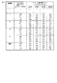
図11のマスク状態の表には、マスク値が0x00に対応する0000や、その他0xffなどのマスキング法に適切でないマスク値に対応するマスク状態が登場しない。このため、マスキング法がサイドチャネル攻撃への対策として適切に動作できる。また、ラウンド鍵更新処理において、ラウンド鍵配列の各要素に適用されているマスク値がラウンド鍵配列の更新操作により図11に示すマスク状態に従って自動的に遷移する。ラウンド鍵配列の各要素のマスク値を明示的に変更する従来の方法では、各要素のマスク値の参照が必要である。本実施形態によれば、ラウンド鍵配列更新処理のたびにマスク値を参照する必要がないが、各要素には適切なマスク値が適用されており、従来の方法と同等以上のサイドチャネル攻撃への対策の効果を得ることができる。 In the mask state table of FIG. 11, there is no mask state corresponding to a mask value that is not appropriate for the masking method, such as 0000 corresponding to 0x00 or 0xff. For this reason, the masking method can operate appropriately as a countermeasure against side channel attacks. Further, in the round key update process, the mask value applied to each element of the round key array is automatically changed according to the mask state shown in FIG. 11 by the update operation of the round key array. In the conventional method of explicitly changing the mask value of each element of the round key array, it is necessary to refer to the mask value of each element. According to the present embodiment, it is not necessary to refer to the mask value every time the round key array update process is performed, but an appropriate mask value is applied to each element, and the side channel attack is equivalent to or better than the conventional method. The effect of this measure can be obtained.
また、第2の実施形態で示したように、0001から1111までの15個のマスク状態に対応したマスクの生成方法の一例としては、任意の既約多項式を用いたガロア体GF(2n)のベクトル表現に対応させることもできる。この場合、多項式表現でいえば、それぞれ1,x,x+1,x^2,x^2+1,x^2+x,x^2+x+1に対応する。例えば、8ビットのデータマスクを生成する場合、乱数rが既約多項式 (x^8+x^7+x^5+x^3+x+1) を用いた拡大体GF(2n)のベクトル表現に対応させると、乱数rのベクトル表現の16進数表記が0x2Cならば、乱数rに基づき、マスク状態0001, 0010,0011, 0100, 0101, 0110, 0111, 1000, 1001, 1010, 1011, 1100, 1101, 1110, 1111に対応して生成されるマスク値は、図13に示すように、それぞれ0x2C, 0x58, 0x74, 0xB0, 0x9C, 0xE8, 0xC4, 0x4B, 0x67, 0x13, 0x3F, 0xFB, 0xD7, 0xA3, 0x8Fとなる。なお、図13中、基本マスク値には、乱数rと、乱数rをそれぞれ2倍、4倍及び8倍した値2r,4r,8rとを用いている。
As shown in the second embodiment, as an example of a mask generation method corresponding to 15 mask states from 0001 to 1111, a Galois field GF (2 n ) using an arbitrary irreducible polynomial is used. It is also possible to correspond to the vector expression. In this case, in terms of polynomial expression, they correspond to 1, x, x + 1, x ^ 2, x ^ 2 + 1, x ^ 2 + x, x ^ 2 + x + 1, respectively. For example, when generating an 8-bit data mask, the random number r is an extension field GF (2 n ) using an irreducible polynomial (x ^ 8 + x ^ 7 + x ^ 5 + x ^ 3 + x + 1). When corresponding to the vector representation, if the hexadecimal representation of the vector representation of the random number r is 0x2C, the mask states 0001, 0010, 0011, 0100, 0101, 0110, 0111, 1000, 1001, 1010, 1011, based on the random number r The mask values generated corresponding to 1100, 1101, 1110, and 1111 are respectively 0x2C, 0x58, 0x74, 0xB0, 0x9C, 0xE8, 0xC4, 0x4B, 0x67, 0x13, 0x3F, 0xFB, as shown in FIG. 0xD7, 0xA3, 0x8F. In FIG. 13, the basic mask value uses a random number r and
いずれにしても、暗号処理装置10は、図12又は図13に示した如き4つの相異なるマスク値に基づき、図11のマスク状態に対応した15種類のマスク値を用いることにより、適切でないマスク値を排除しつつ、効果的なマスキング法を提供することができる。また、図11によるマスク状態の遷移は、図14に示すように、Sボックス出力保護マスク及びラウンド鍵保護マスクの1列目から4列目までは3種類のマスク値から合成されるマスク状態を使用するため、128ビット鍵のAES処理との整合性も高く、複数の鍵長をサポートする暗号処理装置に用いる場合、実装性に優れている。
In any case, the
上述したように本実施形態によれば、第1又は第2の実施形態の効果を、4行6列の192ビット鍵においても得ることができる。 As described above, according to the present embodiment, the effects of the first or second embodiment can be obtained even with a 192-bit key of 4 rows and 6 columns.
(第5の実施形態)
次に、本発明の第5の実施形態に係る暗号処理装置について図15を用いて説明する。本実施形態は、第1又は第2の実施形態を256ビット鍵に適用した形態となっている。
(Fifth embodiment)
Next, a cryptographic processing apparatus according to the fifth embodiment of the present invention will be described with reference to FIG. In this embodiment, the first or second embodiment is applied to a 256-bit key.
これに伴い、CPU4は、ラウンド鍵として256ビット鍵を用いる場合、前述したステップST81−3〜ST81−7の処理と、ステップST91,ST92の処理を再度実行することにより、ラウンド鍵保護マスクの5列目から8列目のマスク値を得る機能をもっている。
Accordingly, when a 256-bit key is used as the round key, the
なお、256ビット鍵のAESでは、図15に示すように、ラウンド鍵配列は4行8列の配列で表現される。先に述べたように、256ビット鍵のラウンド鍵更新において5列目の鍵配列の更新には、4列目の鍵配列にバイト換字(SubByte)処理を適用した結果が用いられるため、4列目のマスク状態と5列目のマスク状態との間に、バイト換字(SubByte)処理で使用されるSボックス出力保護マスクのマスク状態を記述する。 Note that in AES with a 256-bit key, as shown in FIG. 15, the round key array is represented by an array of 4 rows and 8 columns. As described above, in the round key update of a 256-bit key, the result of applying the byte substitution (SubByte) process to the key array of the fourth column is used for updating the key array of the fifth column. Between the mask state of the eye and the mask state of the fifth column, the mask state of the S box output protection mask used in the byte substitution (SubByte) process is described.
図15中、001,010,011,100,101,110,111はそれぞれ3つの独立な基本マスク値のXORで合成されたSボックス出力保護マスク及びラウンド鍵保護マスクのマスク状態を表している。ラウンド鍵保護マスクでは、例えば図7又は図9に示したように、それぞれのマスク状態に対応するマスク値が列毎に割り当てられる。 In FIG. 15, 001, 010, 011, 100, 101, 110, and 111 represent mask states of the S box output protection mask and the round key protection mask synthesized by XOR of three independent basic mask values. In the round key protection mask, for example, as shown in FIG. 7 or FIG. 9, a mask value corresponding to each mask state is assigned to each column.
また前述同様に、図15のマスク状態の表には、適切でないマスク値に対応するマスク状態が登場しないため、サイドチャネル攻撃への対策として適切に動作できる。また同様に、ラウンド鍵更新処理において、ラウンド鍵保護マスクのマスク値が図15に示すマスク状態に従って自動的に遷移する。このため、本実施形態によれば、従来とは異なり、ラウンド鍵配列更新処理のたびにマスク値を参照する必要がない。また、本実施形態によれば、各要素には適切なマスク値が適用されており、従来の方法と同等以上のサイドチャネル攻撃への対策の効果が得られる。 Similarly to the above, since the mask state corresponding to the inappropriate mask value does not appear in the mask state table of FIG. 15, it can operate appropriately as a countermeasure against the side channel attack. Similarly, in the round key update process, the mask value of the round key protection mask automatically changes according to the mask state shown in FIG. Therefore, according to the present embodiment, unlike the conventional case, it is not necessary to refer to the mask value every time the round key array update process is performed. Further, according to the present embodiment, an appropriate mask value is applied to each element, and a countermeasure effect against a side channel attack equal to or higher than that of the conventional method can be obtained.
また、図15によるマスク状態の遷移は、Sボックス出力保護マスク及びラウンド鍵保護マスクには3種類のマスク値から合成されるマスク状態を使用するため、128ビット鍵のAES処理との整合性も高く、複数の鍵長をサポートする暗号処理装置に用いる場合、実装性に優れている。 In addition, since the mask state transition according to FIG. 15 uses a mask state synthesized from three types of mask values for the S box output protection mask and the round key protection mask, consistency with the 128-bit key AES processing is also achieved. When used in a cryptographic processing apparatus that supports a plurality of key lengths, it is excellent in mountability.
上述したように本実施形態によれば、第1又は第2の実施形態の効果を、4行8列の256ビット鍵においても得ることができる。なお、本実施形態では、3つの相異なるマスク値を用いて各マスク状態に対応したマスク値を生成したが、3つ以上の相異なるマスク値であれば同様の方法により各マスク状態を生成でき、例えば第4の実施形態で例示した4つの相異なるマスクによる生成も、この手法の範疇であることは明らかである。 As described above, according to the present embodiment, the effects of the first or second embodiment can be obtained even with a 256-bit key of 4 rows and 8 columns. In this embodiment, mask values corresponding to each mask state are generated using three different mask values, but each mask state can be generated by the same method as long as there are three or more different mask values. For example, it is obvious that the generation using four different masks exemplified in the fourth embodiment is also within the scope of this method.
(第6の実施形態)
次に、本発明の第6の実施形態に係る暗号処理装置について図16乃至図18を用いて説明する。本実施形態は、128ビット鍵の場合を代表例に挙げた第1乃至第5の各実施形態の変形例であり、図16及び図17に示すように、使用段1から最終の使用段までのSボックス出力保護マスク(4行1列)の1行目〜4行目のマスク状態を互いに変更すると共に、ラウンド鍵保護マスクの列毎の1行目から4行目のマスク状態を互いに変更した構成となっている。これに伴い、CPU4は、前述したステップST81−2において、Sボックス出力保護マスクの1行目〜4行目のマスク状態を互いに異なる状態として選択する機能と、前述したステップST81−3〜ST81−5において、ラウンド鍵保護マスクの列毎に1行目から4行目のマスク状態を互いに異なる状態として選択する機能とをもっている。なお、図18は図16及び図17に示すマスク状態に対応したマスク値を表している。
(Sixth embodiment)
Next, a cryptographic processing apparatus according to the sixth embodiment of the present invention will be described with reference to FIGS. This embodiment is a modification of each of the first to fifth embodiments with a 128-bit key as a representative example. As shown in FIGS. 16 and 17, from the
第1乃至第5の実施形態においては、マスク値の例として、8ビットのマスク値を4つ繰り返し1列に拡大した32ビットマスク値を用いたが、0x00のマスク値を除くと、8ビットのマスク値は255通りに限られ、マスク値のランダム性あるいは多様性が限られている。 In the first to fifth embodiments, as an example of the mask value, a 32-bit mask value obtained by repeatedly expanding four 8-bit mask values to one column is used. However, if the mask value of 0x00 is excluded, 8-bit mask values are used. The mask values are limited to 255, and the randomness or diversity of the mask values is limited.
しかしながら、第6の実施形態によれば、鍵配列の各行ごとに独立な4つのマスク値を選択することにより、マスク値の組み合わせを2554 通り、すなわち1658万1375通りまで増加させることができ、マスキング法によるサイドチャネル攻撃への用途としては十分な多様性を提供できる。 However, according to the sixth embodiment, by selecting four independent mask values for each row of the key array, the mask value combinations can be increased to 255 4 ways, that is, 16,581,375 ways, It can provide a wide variety of uses for side channel attacks by masking methods.
上述したように本実施形態によれば、第1乃至第5の各実施形態の効果に加え、Sボックス出力保護マスク及びラウンド鍵保護マスクのマスク値の組み合わせを増加できるため、サイドチャネル攻撃に対する耐性を向上させることができる。 As described above, according to the present embodiment, in addition to the effects of the first to fifth embodiments, the combination of the mask values of the S-box output protection mask and the round key protection mask can be increased, and thus resistance to side channel attacks. Can be improved.
なお、Sボックス出力保護マスクのマスク値の4バイトは独立な値のため、そのまま実装すると4倍の数のマスク付Sボックス情報が必要となるが、図16及び図17のSボックス出力保護マスクのマスク値とは異なる8ビットのマスク値を4つ繰り返すマスク値をSボックス出力保護マスクに用い、その出力に固有のマスク値をそれぞれ適用することにより、図16乃至図18に示すSボックス出力保護マスクのマスク値に変換する実装も、本実施形態の範囲内にある。 Since the 4 bytes of the mask value of the S box output protection mask are independent values, if mounted as they are, four times as many S box information with masks are required, but the S box output protection mask of FIGS. By using a mask value that repeats four 8-bit mask values different from the mask value of 4 for the S box output protection mask and applying a unique mask value to the output, the S box output shown in FIGS. An implementation for converting the mask value of the protection mask is also within the scope of the present embodiment.
(第7の実施形態)
次に、本発明の第7の実施形態に係る暗号処理装置について図19及び図20を用いて説明するが、その前に背景技術を述べる。
(Seventh embodiment)
Next, a cryptographic processing apparatus according to the seventh embodiment of the present invention will be described with reference to FIG. 19 and FIG.
AES暗号方式のデータ暗号化部においては、4行4列で表される中間状態を各列単位でバイト換字(SubByte)処理、ミックスカラム(MixColumn)処理を行い、新しい中間状態の1列を計算する処理を繰り返し、4列の変換を実現する。 In the data encryption part of the AES encryption method, the intermediate state represented by 4 rows and 4 columns is subjected to byte substitution (SubByte) processing and mix column (MixColumn) processing for each column, and one column of new intermediate state is calculated. This process is repeated to realize four columns of conversion.
ここで、サイドチャネル攻撃においては、相似関係にある処理を異なる値を用いて実行する場合、特に攻撃が容易となることが知られている。 Here, in the side channel attack, it is known that when a process having a similar relationship is executed using different values, the attack is particularly easy.
従来の技術によれば、4行4列の内部状態をそれぞれ異なるマスク値で撹乱することにより、サイドチャネル攻撃への対策を行う。従来の技術を図31により説明すると、内部状態行列のy(i,j) (+) r(i,j)は、AESの内部状態のi行j列目に格納されているデータであり、記号(+)は排他的論理和であり、y(i,j)はi行j列目の真の内部状態の成分に、r(i,j)は、i行j列目のマスク値の成分にそれぞれ対応する。 According to the conventional technology, the countermeasure against the side channel attack is performed by disturbing the internal state of 4 rows and 4 columns with different mask values. The prior art will be described with reference to FIG. 31. The internal state matrix y (i, j) (+) r (i, j) is data stored in the i-th row and j-th column of the internal state of AES. Symbol (+) is an exclusive OR, y (i, j) is a true internal state component of i row and j column, and r (i, j) is a mask value of i row and j column. Corresponds to each component.
バイト換字処理においては、4行4列の内部状態の要素毎に異なるマスク値が使用されているため、延べ16個のSボックス情報に個別のマスク値を使用したマスク付きSボックス情報が必要となる。この場合、16種類の異なるマスクのSボックス情報を実現するためには、例えば、RAMに格納すると8キロバイトの記憶容量が必要になり、ハードウェア規模の増大が課題となる。以上が本実施形態の背景技術である。 In byte substitution processing, different mask values are used for each element in the internal state of 4 rows and 4 columns, and therefore S box information with a mask using individual mask values for a total of 16 S box information is required. Become. In this case, in order to realize the S box information of 16 types of different masks, for example, when stored in the RAM, a storage capacity of 8 kilobytes is required, and an increase in hardware scale becomes a problem. The above is the background art of this embodiment.
本実施形態は、第1〜第6の各実施形態と同時に実行可能であって、マスク付バイト換字(SubByte)処理に必要な記憶容量の低減を図るものであり、図19に示すように、Sボックス入力保護マスク及びSボックス出力保護マスクをそれぞれ2種類のマスク値rA,rBから構成し、図20に示すように、CPU4がマスク状態に基づいてSボックス入力保護マスクの付加及びSボックス出力保護マスクの除去を各マスク値rA,rBのXOR演算により実行する構成となっている。
This embodiment can be executed simultaneously with the first to sixth embodiments, and is intended to reduce the storage capacity required for masked byte substitution (SubByte) processing, as shown in FIG. Each of the S box input protection mask and the S box output protection mask is composed of two types of mask values rA and rB. As shown in FIG. 20, the
補足すると、RAM2には、図19に示す如き、Sボックス入力保護マスク及びSボックス出力保護マスクのマスク状態と、当該マスク状態の各ビット値“0”に対応する第1マスク値rAと、当該マスク状態の各ビット値“1”に対応する第2マスク値rBとを互いに関連付けた参照表データが記憶されている。
Supplementally, in the
CPU4は、選択したSボックス入力保護マスク及びSボックス出力保護マスクのマスク状態に基づいて、RAM2内の参照表データを参照し、当該マスク状態の各ビット値“0”又は“1”に対応して第1マスク値rA又は第2マスク値rBを選択する機能とをもっている。
The
ここで、図20に示す内部状態行列のy(i,j) (+) r(j)は、AESの内部状態のi行j列目に格納されているデータであり、記号(+)は排他的論理和であり、y(i,j)はi行j列目の真の内部状態の成分に、r(j)は、j列目のマスク値の成分にそれぞれ対応する。 Here, y (i, j) (+) r (j) in the internal state matrix shown in FIG. 20 is data stored in the i-th row and j-th column of the internal state of AES, and the symbol (+) is This is an exclusive OR, and y (i, j) corresponds to the component of the true internal state in the i-th row and j-th column, and r (j) corresponds to the component of the mask value in the j-th column.
マスク値は、CPU4がマスク状態に基づいて図19の参照表データを参照することにより、決定される。具体的には、CPU4は、マスク状態0000から1111までの16種類のマスク状態に対応して、r(1)からr(4)までの各列の4つのマスク値にrA又はrBを選択し、列毎にSボックス入力保護マスク及び/又はSボックス出力保護マスクのマスク値を変更する。これにより、相似した処理で参照されるマスクされたSボックス情報の表が、列毎に2種類の表から選択されるため、任意の列の間においてSボックス情報のマスク値が一致する確率が2分の1となる。
The mask value is determined by the
第2から第6の実施形態においては、3つ又は4つの基本マスク値から合成された7種類又は15種類のマスク値をラウンド鍵へのマスキング法に用いている。一方、AESの暗号処理においては、マスク付バイト換字処理のSボックス情報の参照において図19のマスク状態に対応したマスク値に変更する。 In the second to sixth embodiments, seven or fifteen types of mask values synthesized from three or four basic mask values are used for the masking method to the round key. On the other hand, in the AES encryption processing, the mask value corresponding to the mask state in FIG. 19 is changed in reference to the S box information in the masked byte substitution processing.
上述したように本実施形態によれば、1つ又は2つの基本マスク値rA,rBをSボックス入力保護マスクあるいはSボックス出力保護マスクのマスク値に用い、CPU4による選択処理で切り替えることにより、処理あるいはラウンド毎に且つ列毎にSボックス保護マスクのマスク値を変化させることができ、サイドチャネル攻撃に有効な情報の漏洩を低減でき、安全性が高まる効果がある。
As described above, according to the present embodiment, one or two basic mask values rA and rB are used as mask values for the S box input protection mask or the S box output protection mask, and are switched by selection processing by the
以上説明した各実施形態ではAESの暗号化処理の処理手順をもって説明したが、暗号化処理と対称をなす復号処理に対しても、当業者であれば上述の実施形態の種々の変形を行えることは明らかである。 In each of the embodiments described above, the processing procedure of the AES encryption process has been described. However, a person skilled in the art can perform various modifications of the above-described embodiment for a decryption process that is symmetric to the encryption process. Is clear.
また、各実施形態のうち、データ暗号化部に関する第7の実施形態は、AES暗号方式に限らず、例えばISO/IEC 10118−3に記載のワープールWhirlpoolのように、AES暗号方式と類似したアルゴリズムについても適用可能となっている。ここで、ワープールWhirlpoolは、AES暗号方式に類似したデータ暗号化部を有しており、鍵スケジュール部が無い構成となっている。これに伴い、第7の実施形態は、ワープールWhirlpoolにも適用可能となっている。 In addition, among the embodiments, the seventh embodiment related to the data encryption unit is not limited to the AES encryption method, but is an algorithm similar to the AES encryption method, for example, the word pool Whirlpool described in ISO / IEC 10118-3. Is also applicable. Here, the word pool Whirlpool has a data encryption unit similar to the AES encryption method, and has no key schedule unit. Accordingly, the seventh embodiment can be applied to the word pool Whirlpool.
ワープールWhirlpoolに関する変形例は、図1に示す暗号処理プログラムを、Sボックス入力保護マスク及びSボックス出力保護マスクを用い、ISO/IEC 10118−3に記載のワープールWhirlpoolを実行する暗号処理装置のプログラムとすればよい。このプログラムの実行により、CPU4は、Sボックス入力保護マスクのマスク状態を“001”,“010”,“011”,“100”,“101”,“110”及び“111”の7種類のマスク状態から選択する入力選択機能と、選択されたSボックス入力保護マスクのマスク状態とは異なるマスク状態を、Sボックス出力保護マスクのマスク状態として7種類のマスク状態から選択する出力選択機能と、Sボックス入力保護マスク及びSボックス出力保護マスクのマスク状態と、当該マスク状態の各ビット値“0”に対応する第1マスク値と、当該マスク状態の各ビット値“1”に対応する第2マスク値とを互いに関連付けた参照表データをRAM2に書き込む機能と、入力選択機能及び出力選択機能により選択したマスク状態に基づいて、RAM2内の参照表データを参照し、当該マスク状態の各ビット値“0”又は“1”に対応して第1マスク値又は第2マスク値を選択するマスク値選択機能とを備えている。このワープールWhirlpoolに関する変形例によれば、第7の実施形態と同様に、処理あるいはラウンド毎に且つ列毎にSボックス保護マスクのマスク値を変化させることができ、サイドチャネル攻撃に有効な情報の漏洩を低減でき、安全性が高まる効果がある。
A modification of the Warpool Whirlpool is the same as the encryption processing program shown in FIG. 1 that uses the S-box input protection mask and the S-box output protection mask to execute the Warpool Whirlpool described in ISO / IEC 10118-3. do it. By executing this program, the
また、各実施形態は、暗号処理を実行するデバイス、例えば暗号処理モジュールを持つICカードあるいはその他の暗号処理装置に適用可能である。また、各実施形態の構成を適用することにより、電力解析によるICモジュール内の暗号処理鍵やアルゴリズムの漏洩が困難となるので、セキュリティレベルの高い暗号処理実行機能を持つデバイスあるいは装置を提供することができる。 Each embodiment can be applied to a device that performs cryptographic processing, for example, an IC card having a cryptographic processing module or other cryptographic processing apparatus. Also, by applying the configuration of each embodiment, it becomes difficult to leak cryptographic processing keys and algorithms in the IC module by power analysis, and thus a device or apparatus having a cryptographic processing execution function with a high security level is provided. Can do.
なお、上記実施形態に記載した手法は、コンピュータに実行させることのできるプログラムとして、磁気ディスク(フロッピー(登録商標)ディスク、ハードディスクなど)、光ディスク(CD−ROM、DVDなど)、光磁気ディスク(MO)、半導体メモリなどの記憶媒体に格納して頒布することもできる。 Note that the method described in the above embodiment is a program that can be executed by a computer, such as a magnetic disk (floppy (registered trademark) disk, hard disk, etc.), an optical disk (CD-ROM, DVD, etc.), a magneto-optical disk (MO). ), And can be distributed in a storage medium such as a semiconductor memory.
また、この記憶媒体としては、プログラムを記憶でき、かつコンピュータが読み取り可能な記憶媒体であれば、その記憶形式は何れの形態であっても良い。 In addition, as long as the storage medium can store a program and can be read by a computer, the storage format may be any form.
また、記憶媒体からコンピュータにインストールされたプログラムの指示に基づきコンピュータ上で稼働しているOS(オペレーティングシステム)や、データベース管理ソフト、ネットワークソフト等のMW(ミドルウェア)等が上記実施形態を実現するための各処理の一部を実行しても良い。 In addition, an OS (operating system) running on a computer based on an instruction of a program installed in the computer from a storage medium, MW (middleware) such as database management software, network software, and the like realize the above-described embodiment. A part of each process may be executed.
さらに、本発明における記憶媒体は、コンピュータと独立した媒体に限らず、LANやインターネット等により伝送されたプログラムをダウンロードして記憶又は一時記憶した記憶媒体も含まれる。 Furthermore, the storage medium in the present invention is not limited to a medium independent of a computer, but also includes a storage medium in which a program transmitted via a LAN or the Internet is downloaded and stored or temporarily stored.
また、記憶媒体は1つに限らず、複数の媒体から上記実施形態における処理が実行される場合も本発明における記憶媒体に含まれ、媒体構成は何れの構成であっても良い。 Further, the number of storage media is not limited to one, and the case where the processing in the above embodiment is executed from a plurality of media is also included in the storage media in the present invention, and the media configuration may be any configuration.
尚、本発明におけるコンピュータは、記憶媒体に記憶されたプログラムに基づき、上記実施形態における各処理を実行するものであって、パソコン等の1つからなる装置、複数の装置がネットワーク接続されたシステム等の何れの構成であっても良い。 The computer according to the present invention executes each process in the above-described embodiment based on a program stored in a storage medium, and is a single device such as a personal computer or a system in which a plurality of devices are connected to a network. Any configuration may be used.
また、本発明におけるコンピュータとは、パソコンに限らず、情報処理機器に含まれる演算処理装置、マイコン等も含み、プログラムによって本発明の機能を実現することが可能な機器、装置を総称している。 In addition, the computer in the present invention is not limited to a personal computer, but includes an arithmetic processing device, a microcomputer, and the like included in an information processing device, and is a generic term for devices and devices that can realize the functions of the present invention by a program. .
なお、本願発明は、上記実施形態そのままに限定されるものではなく、実施段階ではその要旨を逸脱しない範囲で構成要素を変形して具体化できる。また、上記実施形態に開示されている複数の構成要素の適宜な組合せにより種々の発明を形成できる。例えば、実施形態に示される全構成要素から幾つかの構成要素を削除してもよい。更に、異なる実施形態に亘る構成要素を適宜組合せてもよい。 Note that the present invention is not limited to the above-described embodiment as it is, and can be embodied by modifying the constituent elements without departing from the scope of the invention in the implementation stage. Moreover, various inventions can be formed by appropriately combining a plurality of constituent elements disclosed in the embodiment. For example, some components may be deleted from all the components shown in the embodiment. Furthermore, constituent elements over different embodiments may be appropriately combined.
10…暗号処理装置、1…ROM、2…RAM、3…不揮発性メモリ、4…CPU、5…入出力部、6…バス。
DESCRIPTION OF
Claims (12)
前記Sボックス入力保護マスクのマスク状態を“001”,“010”,“011”,“100”,“101”,“110”及び“111”の7種類のマスク状態から選択する入力選択手段と、
前記選択されたSボックス入力保護マスクのマスク状態とは異なるマスク状態を、前記Sボックス出力保護マスクのマスク状態として前記7種類のマスク状態から選択する出力選択手段と、
前記選択されたSボックス出力保護マスクのマスク状態とは異なるマスク状態を、前記ラウンド鍵保護マスクの1列目のマスク状態として前記7種類のマスク状態から選択する1列目選択手段と、
前記選択されたSボックス出力保護マスクのマスク状態、前記選択された1列目のマスク状態、及び「当該Sボックス出力保護マスクのマスク状態と当該1列目のマスク状態との排他的論理和の演算結果」とは異なるマスク状態を、前記ラウンド鍵保護マスクの2列目のマスク状態として前記7種類のマスク状態から選択する2列目手段と、
前記ラウンド鍵保護マスクの3列目及び4列目のマスク状態を前記7種類のマスク状態からそれぞれ選択する3・4列目選択手段と、
前記選択されたSボックス出力保護マスクのマスク状態、前記選択された1列目から4列目までのマスク状態を用いて、前記AES暗号方式によるラウンド鍵更新後の1列目から4列目までのマスク状態を計算するマスク状態計算手段と、
前記計算されたマスク状態に禁止状態“000”が含まれるか否かを判定する禁止状態判定手段と、
前記7種類のマスク状態のうち、“001”,“010”及び“100”にそれぞれ対応する3個の基本マスク値が記憶された基本マスク値記憶手段と、
前記禁止状態が含まれないとき、前記選択された各マスク状態に対応して前記各基本マスク値同士を排他的論理和により合成することにより、当該選択された各マスク状態に対応するそれぞれの合成マスク値を計算するマスク値計算手段と
を備えたことを特徴とする暗号処理装置。 An encryption processing apparatus that executes an AES encryption method using a round key protection mask, an S box input protection mask, and an S box output protection mask,
An input selection means for selecting the mask state of the S box input protection mask from seven mask states of “001”, “010”, “011”, “100”, “101”, “110”, and “111”; ,
Output selecting means for selecting a mask state different from the mask state of the selected S box input protection mask from the seven types of mask states as a mask state of the S box output protection mask;
First column selection means for selecting a mask state different from the mask state of the selected S box output protection mask from the seven types of mask states as the mask state of the first column of the round key protection mask;
The mask state of the selected S box output protection mask, the mask state of the selected first column, and “the exclusive OR of the mask state of the S box output protection mask and the mask state of the first column” A second column means for selecting a mask state different from the “operation result” from the seven types of mask states as the second column mask state of the round key protection mask;
Third and fourth column selection means for selecting the mask states of the third and fourth columns of the round key protection mask from the seven types of mask states, respectively.
Using the mask state of the selected S-box output protection mask and the selected mask state from the first column to the fourth column, from the first column to the fourth column after the round key update by the AES encryption method Mask state calculation means for calculating the mask state of
Forbidden state determining means for determining whether or not the calculated mask state includes a forbidden state “000”;
A basic mask value storage means for storing three basic mask values respectively corresponding to “001”, “010” and “100” among the seven types of mask states;
When the prohibition state is not included, each of the basic mask values corresponding to each of the selected mask states is synthesized by exclusive OR, thereby combining each of the selected mask states. An encryption processing apparatus comprising: a mask value calculation means for calculating a mask value.
前記ラウンド鍵として256ビット鍵を用いる場合、前記1列目選択手段、前記2列目選択手段、前記3・4列目選択手段、前記マスク状態計算手段、前記禁止状態判定手段、前記マスク値計算手段を再度実行することにより、前記ラウンド鍵保護マスクの5列目から8列目のマスク値を得る手段を備えたことを特徴とする暗号処理装置。 The cryptographic processing device according to claim 1,
When a 256-bit key is used as the round key, the first column selection unit, the second column selection unit, the third and fourth column selection unit, the mask state calculation unit, the prohibition state determination unit, the mask value calculation An encryption processing apparatus comprising means for obtaining mask values in the fifth to eighth columns of the round key protection mask by executing the means again.
前記ラウンド鍵として192ビット鍵を用いる場合、前記ラウンド鍵保護マスクの5列目及び6列目のマスク状態を“1000”,“1001”,“1010”,“1011”,“1100”,“1101”,“1110”及び“1111”の8種類のマスク状態からそれぞれ選択する5・6列目選択手段と、
前記計算された4列目のマスク状態を用いて、前記AES暗号方式によるラウンド鍵更新後の5列目及び6列目のマスク状態を計算する第2のマスク状態計算手段と、
前記計算された5列目及び6列目のマスク状態に禁止状態“0000”が含まれるか否かを判定する第2の禁止状態判定手段と、
前記8種類のマスク状態のうち、“1000”に対応する基本マスク値が記憶された第2の基本マスク値記憶手段と、
前記禁止状態“0000”が含まれないとき、前記選択された5列目及び6列目の各マスク状態に対応して前記各基本マスク値同士を排他的論理和により合成することにより、当該5列目及び6列目の各マスク状態に対応するそれぞれの合成マスク値を計算する第2のマスク値計算手段と
を備えたことを特徴とする暗号処理装置。 The cryptographic processing device according to claim 1,
When a 192-bit key is used as the round key, the mask states of the fifth and sixth columns of the round key protection mask are “1000”, “1001”, “1010”, “1011”, “1100”, “1101”. 5th and 6th column selection means for selecting from 8 types of mask states, “1110” and “1111” respectively;
Second mask state calculation means for calculating the mask states of the fifth column and the sixth column after the round key update by the AES encryption method, using the calculated mask state of the fourth column;
Second prohibition state determination means for determining whether or not the calculated mask states of the fifth and sixth columns include a prohibition state “0000”;
A second basic mask value storage means storing a basic mask value corresponding to “1000” among the eight types of mask states;
When the prohibited state “0000” is not included, the basic mask values are synthesized by exclusive OR in correspondence with the selected mask states of the fifth column and the sixth column. And a second mask value calculating means for calculating respective composite mask values corresponding to the mask states in the columns and the sixth column.
前記基本マスク値のビット数“8”と同一ビット数の乱数rを生成する手段と、
前記ビット数と同一値の次数である8次の既約多項式を選択する手段とを備えており、
前記基本マスク値は、前記乱数rと、前記乱数rをそれぞれ2倍及び4倍した値2r,4rとであり、
前記マスク値計算手段は、前記既約多項式を用いたガロア体GF(28)のベクトル表現を前記マスク状態に対応させることにより、前記マスク値を計算することを特徴とする暗号処理装置。 The cryptographic processing apparatus according to any one of claims 1 to 3,
Means for generating a random number r having the same number of bits as the number of bits “8” of the basic mask value;
Means for selecting an eighth degree irreducible polynomial having the same value as the number of bits,
The basic mask values are the random number r, and values 2r and 4r obtained by doubling and quadrupling the random number r, respectively.
The cryptographic processing apparatus, wherein the mask value calculation means calculates the mask value by associating a vector representation of a Galois field GF (2 8 ) using the irreducible polynomial with the mask state.
前記Sボックス入力保護マスク及び前記Sボックス出力保護マスクのマスク状態と、当該マスク状態の各ビット値“0”に対応する第1マスク値と、当該マスク状態の各ビット値“1”に対応する第2マスク値とを互いに関連付けて記憶したマスク値対応情報記憶手段と、
前記入力選択手段及び前記出力選択手段により選択されたマスク状態に基づいて、前記マスク値対応情報記憶手段を参照し、当該マスク状態の各ビット値“0”又は“1”に対応して前記第1マスク値又は第2マスク値を選択するマスク値選択手段と
を備えたことを特徴とする暗号処理装置。 The cryptographic processing apparatus according to any one of claims 1 to 4, wherein
The mask state of the S box input protection mask and the S box output protection mask, the first mask value corresponding to each bit value “0” of the mask state, and the bit value “1” of the mask state Mask value correspondence information storage means for storing the second mask value in association with each other;
Based on the mask state selected by the input selection means and the output selection means, the mask value correspondence information storage means is referred to, and the first value corresponding to each bit value “0” or “1” of the mask state is referred to. An encryption processing apparatus comprising: mask value selection means for selecting one mask value or a second mask value.
前記Sボックス入力保護マスクのマスク状態を“001”,“010”,“011”,“100”,“101”,“110”及び“111”の7種類のマスク状態から選択する入力選択手段と、
前記選択されたSボックス入力保護マスクのマスク状態とは異なるマスク状態を、前記Sボックス出力保護マスクのマスク状態として前記7種類のマスク状態から選択する出力選択手段と、
前記Sボックス入力保護マスク及び前記Sボックス出力保護マスクのマスク状態と、当該マスク状態の各ビット値“0”に対応する第1マスク値と、当該マスク状態の各ビット値“1”に対応する第2マスク値とを互いに関連付けて記憶したマスク値対応情報記憶手段と、
前記入力選択手段及び前記出力選択手段により選択されたマスク状態に基づいて、前記マスク値対応情報記憶手段を参照し、当該マスク状態の各ビット値“0”又は“1”に対応して前記第1マスク値又は第2マスク値を選択するマスク値選択手段と
を備えたことを特徴とする暗号処理装置。 An encryption processing device that executes the word pool Whirlpool described in ISO / IEC 10118-3 using an S box input protection mask and an S box output protection mask,
An input selection means for selecting the mask state of the S box input protection mask from seven mask states of “001”, “010”, “011”, “100”, “101”, “110”, and “111”; ,
Output selecting means for selecting a mask state different from the mask state of the selected S box input protection mask from the seven types of mask states as a mask state of the S box output protection mask;
The mask state of the S box input protection mask and the S box output protection mask, the first mask value corresponding to each bit value “0” of the mask state, and the bit value “1” of the mask state Mask value correspondence information storage means for storing the second mask value in association with each other;
Based on the mask state selected by the input selection means and the output selection means, the mask value correspondence information storage means is referred to, and the first value corresponding to each bit value “0” or “1” of the mask state is referred to. An encryption processing apparatus comprising: mask value selection means for selecting one mask value or a second mask value.
前記暗号処理装置のコンピュータを、
前記Sボックス入力保護マスクのマスク状態を“001”,“010”,“011”,“100”,“101”,“110”及び“111”の7種類のマスク状態から選択する入力選択手段、
前記選択されたSボックス入力保護マスクのマスク状態とは異なるマスク状態を、前記Sボックス出力保護マスクのマスク状態として前記7種類のマスク状態から選択する出力選択手段、
前記選択されたSボックス出力保護マスクのマスク状態とは異なるマスク状態を、前記ラウンド鍵保護マスクの1列目のマスク状態として前記7種類のマスク状態から選択する1列目選択手段、
前記選択されたSボックス出力保護マスクのマスク状態、前記選択された1列目のマスク状態、及び「当該Sボックス出力保護マスクのマスク状態と当該1列目のマスク状態との排他的論理和の演算結果」とは異なるマスク状態を、前記ラウンド鍵保護マスクの2列目のマスク状態として前記7種類のマスク状態から選択する2列目手段、
前記ラウンド鍵保護マスクの3列目及び4列目のマスク状態を前記7種類のマスク状態からそれぞれ選択する3・4列目選択手段、
前記選択されたSボックス出力保護マスクのマスク状態、前記選択された1列目から4列目までのマスク状態を用いて、前記AES暗号方式によるラウンド鍵更新後の1列目から4列目までのマスク状態を計算するマスク状態計算手段、
前記計算されたマスク状態に禁止状態“000”が含まれるか否かを判定する禁止状態判定手段、
前記7種類のマスク状態のうち、“001”,“010”及び“100”にそれぞれ対応する3個の基本マスク値を前記コンピュータのメモリに書き込む手段、
前記禁止状態が含まれないとき、前記選択された各マスク状態に対応して前記各基本マスク値同士を排他的論理和により合成することにより、当該選択された各マスク状態に対応するそれぞれの合成マスク値を計算するマスク値計算手段、
として機能させるためのプログラム。 A program of an encryption processing apparatus that executes an AES encryption method using a round key protection mask, an S box input protection mask, and an S box output protection mask,
A computer of the cryptographic processing apparatus;
An input selection means for selecting the mask state of the S box input protection mask from seven mask states of “001”, “010”, “011”, “100”, “101”, “110” and “111”;
Output selecting means for selecting a mask state different from the mask state of the selected S box input protection mask from the seven types of mask states as a mask state of the S box output protection mask;
A first column selection means for selecting a mask state different from the mask state of the selected S box output protection mask from the seven types of mask states as a mask state of the first column of the round key protection mask;
The mask state of the selected S box output protection mask, the mask state of the selected first column, and “the exclusive OR of the mask state of the S box output protection mask and the mask state of the first column” A second column means for selecting a mask state different from the “calculation result” from the seven types of mask states as the second column mask state of the round key protection mask;
Third and fourth column selection means for selecting the mask states of the third column and the fourth column of the round key protection mask from the seven types of mask states, respectively.
Using the mask state of the selected S-box output protection mask and the selected mask state from the first column to the fourth column, from the first column to the fourth column after the round key update by the AES encryption method Mask state calculating means for calculating the mask state of
Prohibition state determination means for determining whether or not the calculated mask state includes a prohibition state “000”;
Means for writing three basic mask values respectively corresponding to “001”, “010” and “100” among the seven types of mask states to the memory of the computer;
When the prohibition state is not included, each of the basic mask values corresponding to each of the selected mask states is synthesized by exclusive OR, thereby combining each of the selected mask states. Mask value calculation means for calculating a mask value;
Program to function as.
前記コンピュータを、
前記ラウンド鍵として256ビット鍵を用いる場合、前記1列目選択手段、前記2列目選択手段、前記3・4列目選択手段、前記マスク状態計算手段、前記禁止状態判定手段、前記マスク値計算手段を再度実行することにより、前記ラウンド鍵保護マスクの5列目から8列目のマスク値を得る手段として機能させるためのプログラム。 The program according to claim 7,
The computer,
When a 256-bit key is used as the round key, the first column selection unit, the second column selection unit, the third and fourth column selection unit, the mask state calculation unit, the prohibition state determination unit, the mask value calculation A program for functioning as means for obtaining mask values in the fifth to eighth columns of the round key protection mask by executing the means again.
前記コンピュータを、
前記ラウンド鍵として192ビット鍵を用いる場合、前記ラウンド鍵保護マスクの5列目及び6列目のマスク状態を“1000”,“1001”,“1010”,“1011”,“1100”,“1101”,“1110”及び“1111”の8種類のマスク状態からそれぞれ選択する5・6列目選択手段、
前記計算された4列目のマスク状態を用いて、前記AES暗号方式によるラウンド鍵更新後の5列目及び6列目のマスク状態を計算する第2のマスク状態計算手段、
前記計算された5列目及び6列目のマスク状態に禁止状態“0000”が含まれるか否かを判定する第2の禁止状態判定手段、
前記8種類のマスク状態のうち、“1000”に対応する基本マスク値を前記メモリに書き込む手段、
前記禁止状態“0000”が含まれないとき、前記選択された5列目及び6列目の各マスク状態に対応して前記各基本マスク値同士を排他的論理和により合成することにより、当該5列目及び6列目の各マスク状態に対応するそれぞれの合成マスク値を計算する第2のマスク値計算手段、
として機能させるためのプログラム。 The program according to claim 7,
The computer,
When a 192-bit key is used as the round key, the mask states of the fifth and sixth columns of the round key protection mask are “1000”, “1001”, “1010”, “1011”, “1100”, “1101”. 5th and 6th column selection means for selecting from 8 types of mask states, “1110” and “1111”,
Second mask state calculation means for calculating the mask states of the fifth column and the sixth column after the round key update by the AES encryption method, using the calculated mask state of the fourth column;
Second prohibition state determination means for determining whether or not the calculated mask states of the fifth and sixth columns include a prohibition state “0000”;
Means for writing a basic mask value corresponding to “1000” among the eight mask states to the memory;
When the prohibited state “0000” is not included, the basic mask values are synthesized by exclusive OR in correspondence with the selected mask states of the fifth column and the sixth column. Second mask value calculation means for calculating respective composite mask values corresponding to the mask states in the columns and the sixth column,
Program to function as.
前記コンピュータを、
前記基本マスク値のビット数“8”と同一ビット数の乱数rを生成する手段、
前記ビット数と同一値の次数である8次の既約多項式を選択する手段、として機能させ、
前記基本マスク値は、前記乱数rと、前記乱数rをそれぞれ2倍及び4倍した値2r,4rとであり、
前記マスク値計算手段は、前記既約多項式を用いたガロア体GF(28)のベクトル表現を前記マスク状態に対応させることにより、前記マスク値を計算することを特徴とするプログラム。 The program according to any one of claims 7 to 9,
The computer,
Means for generating a random number r having the same number of bits as the number of bits “8” of the basic mask value;
Function as a means for selecting an eighth degree irreducible polynomial having the same value as the number of bits,
The basic mask values are the random number r, and values 2r and 4r obtained by doubling and quadrupling the random number r, respectively.
The mask value calculating means calculates the mask value by associating a vector representation of a Galois field GF (2 8 ) using the irreducible polynomial with the mask state.
前記暗号処理装置のコンピュータを、
前記Sボックス入力保護マスク及び前記Sボックス出力保護マスクのマスク状態と、当該マスク状態の各ビット値“0”に対応する第1マスク値と、当該マスク状態の各ビット値“1”に対応する第2マスク値とを互いに関連付けた参照表データを前記コンピュータのメモリに書き込む手段、
前記入力選択手段及び前記出力選択手段により選択されたマスク状態に基づいて、前記メモリ内の参照表データを参照し、当該マスク状態の各ビット値“0”又は“1”に対応して前記第1マスク値又は第2マスク値を選択するマスク値選択手段、
として機能させるためのプログラム。 A program according to any one of claims 7 to 10,
A computer of the cryptographic processing apparatus;
The mask state of the S box input protection mask and the S box output protection mask, the first mask value corresponding to each bit value “0” of the mask state, and the bit value “1” of the mask state Means for writing the reference table data associated with the second mask value into the memory of the computer;
Based on the mask state selected by the input selection means and the output selection means, the reference table data in the memory is referred to, and the first value corresponding to each bit value “0” or “1” of the mask state is referred to. Mask value selection means for selecting one mask value or second mask value;
Program to function as.
前記暗号処理装置のコンピュータを、
前記Sボックス入力保護マスクのマスク状態を“001”,“010”,“011”,“100”,“101”,“110”及び“111”の7種類のマスク状態から選択する入力選択手段、
前記選択されたSボックス入力保護マスクのマスク状態とは異なるマスク状態を、前記Sボックス出力保護マスクのマスク状態として前記7種類のマスク状態から選択する出力選択手段、
前記Sボックス入力保護マスク及び前記Sボックス出力保護マスクのマスク状態と、当該マスク状態の各ビット値“0”に対応する第1マスク値と、当該マスク状態の各ビット値“1”に対応する第2マスク値とを互いに関連付けた参照表データを前記コンピュータのメモリに書き込む手段、
前記入力選択手段及び前記出力選択手段により選択されたマスク状態に基づいて、前記メモリ内の参照表データを参照し、当該マスク状態の各ビット値“0”又は“1”に対応して前記第1マスク値又は第2マスク値を選択するマスク値選択手段、
として機能させるためのプログラム。 A program of a cryptographic processing apparatus that executes a word pool Whirlpool described in ISO / IEC 10118-3 using an S box input protection mask and an S box output protection mask,
A computer of the cryptographic processing apparatus;
An input selection means for selecting the mask state of the S box input protection mask from seven mask states of “001”, “010”, “011”, “100”, “101”, “110” and “111”;
Output selecting means for selecting a mask state different from the mask state of the selected S box input protection mask from the seven types of mask states as a mask state of the S box output protection mask;
The mask state of the S box input protection mask and the S box output protection mask, the first mask value corresponding to each bit value “0” of the mask state, and the bit value “1” of the mask state Means for writing the reference table data associated with the second mask value into the memory of the computer;
Based on the mask state selected by the input selection means and the output selection means, the reference table data in the memory is referred to, and the first value corresponding to each bit value “0” or “1” of the mask state is referred to. Mask value selection means for selecting one mask value or second mask value;
Program to function as.
Priority Applications (1)
| Application Number | Priority Date | Filing Date | Title |
|---|---|---|---|
| JP2007075452A JP2008233683A (en) | 2007-03-22 | 2007-03-22 | Cryptographic processing apparatus and program |
Applications Claiming Priority (1)
| Application Number | Priority Date | Filing Date | Title |
|---|---|---|---|
| JP2007075452A JP2008233683A (en) | 2007-03-22 | 2007-03-22 | Cryptographic processing apparatus and program |
Publications (1)
| Publication Number | Publication Date |
|---|---|
| JP2008233683A true JP2008233683A (en) | 2008-10-02 |
Family
ID=39906510
Family Applications (1)
| Application Number | Title | Priority Date | Filing Date |
|---|---|---|---|
| JP2007075452A Withdrawn JP2008233683A (en) | 2007-03-22 | 2007-03-22 | Cryptographic processing apparatus and program |
Country Status (1)
| Country | Link |
|---|---|
| JP (1) | JP2008233683A (en) |
Cited By (15)
| Publication number | Priority date | Publication date | Assignee | Title |
|---|---|---|---|---|
| JP2010057066A (en) * | 2008-08-29 | 2010-03-11 | Toshiba Corp | Apparatus, method and program for scheduling key to be used for encryption |
| WO2010103928A1 (en) * | 2009-03-10 | 2010-09-16 | 株式会社 東芝 | Calculating device and program |
| JP2011109662A (en) * | 2009-11-18 | 2011-06-02 | St Microelectronics (Rousset) Sas | Method and apparatus for detecting fault utilizing attack |
| JP2012004888A (en) * | 2010-06-17 | 2012-01-05 | Kddi Corp | Logical operation device, logical operation method and program |
| JP2012063700A (en) * | 2010-09-17 | 2012-03-29 | Toshiba Corp | Encryption device |
| JP2012520589A (en) * | 2009-03-10 | 2012-09-06 | イルデト・コーポレート・ビー・ヴイ | White-box cryptosystem using input-dependent encoding |
| WO2012131926A1 (en) * | 2011-03-29 | 2012-10-04 | 富士通株式会社 | Encryption processing device, authentication method and program |
| JP2013029835A (en) * | 2011-07-26 | 2013-02-07 | Crocus Technology Sa | Countermeasure against side-channel attacks |
| JP2016090710A (en) * | 2014-10-31 | 2016-05-23 | 株式会社東海理化電機製作所 | Cryptographic processing device |
| JP2018515812A (en) * | 2015-05-19 | 2018-06-14 | コーニンクレッカ フィリップス エヌ ヴェKoninklijke Philips N.V. | Calculation with encrypted value |
| CN114258660A (en) * | 2019-03-18 | 2022-03-29 | Pq盾牌有限公司 | Cryptographic architecture for cryptographic permutations |
| JP2022054400A (en) * | 2020-09-25 | 2022-04-06 | インテル・コーポレーション | Cache set permutation based on galois field operation |
| CN119232357A (en) * | 2023-06-28 | 2024-12-31 | 合肥忆芯电子科技有限公司 | S-box circuit resistant to power consumption analysis |
| US12229323B2 (en) | 2019-08-16 | 2025-02-18 | Pqshield Ltd. | Co-processor for cryptographic operations |
| US12470376B2 (en) | 2021-07-15 | 2025-11-11 | Pqshield Ltd | Cryptographic system for post-quantum cryptographic operations |
-
2007
- 2007-03-22 JP JP2007075452A patent/JP2008233683A/en not_active Withdrawn
Cited By (23)
| Publication number | Priority date | Publication date | Assignee | Title |
|---|---|---|---|---|
| JP2010057066A (en) * | 2008-08-29 | 2010-03-11 | Toshiba Corp | Apparatus, method and program for scheduling key to be used for encryption |
| US8631249B2 (en) | 2009-03-10 | 2014-01-14 | Kabushiki Kaisha Toshiba | Operation unit and program |
| WO2010103928A1 (en) * | 2009-03-10 | 2010-09-16 | 株式会社 東芝 | Calculating device and program |
| JP2010210940A (en) * | 2009-03-10 | 2010-09-24 | Toshiba Corp | Calculation device and program |
| JP2012520589A (en) * | 2009-03-10 | 2012-09-06 | イルデト・コーポレート・ビー・ヴイ | White-box cryptosystem using input-dependent encoding |
| US9654280B2 (en) | 2009-03-10 | 2017-05-16 | Irdeto B.V. | White-box cryptographic system with input dependent encodings |
| JP2011109662A (en) * | 2009-11-18 | 2011-06-02 | St Microelectronics (Rousset) Sas | Method and apparatus for detecting fault utilizing attack |
| JP2012004888A (en) * | 2010-06-17 | 2012-01-05 | Kddi Corp | Logical operation device, logical operation method and program |
| JP2012063700A (en) * | 2010-09-17 | 2012-03-29 | Toshiba Corp | Encryption device |
| JP5556955B2 (en) * | 2011-03-29 | 2014-07-23 | 富士通株式会社 | Cryptographic processing apparatus, authentication method, and program |
| WO2012131926A1 (en) * | 2011-03-29 | 2012-10-04 | 富士通株式会社 | Encryption processing device, authentication method and program |
| JP2013029835A (en) * | 2011-07-26 | 2013-02-07 | Crocus Technology Sa | Countermeasure against side-channel attacks |
| JP2016090710A (en) * | 2014-10-31 | 2016-05-23 | 株式会社東海理化電機製作所 | Cryptographic processing device |
| JP2018515812A (en) * | 2015-05-19 | 2018-06-14 | コーニンクレッカ フィリップス エヌ ヴェKoninklijke Philips N.V. | Calculation with encrypted value |
| JP2022541057A (en) * | 2019-03-18 | 2022-09-21 | ピーキューシールド・リミテッド | Cryptographic architecture for cryptographic permutation |
| CN114258660A (en) * | 2019-03-18 | 2022-03-29 | Pq盾牌有限公司 | Cryptographic architecture for cryptographic permutations |
| JP7646625B2 (en) | 2019-03-18 | 2025-03-17 | ピーキューシールド・リミテッド | Cryptographic architecture for cipher substitution |
| US12474891B2 (en) | 2019-03-18 | 2025-11-18 | Pqshield Ltd | Cryptographic architecture for cryptographic permutation |
| US12229323B2 (en) | 2019-08-16 | 2025-02-18 | Pqshield Ltd. | Co-processor for cryptographic operations |
| JP2022054400A (en) * | 2020-09-25 | 2022-04-06 | インテル・コーポレーション | Cache set permutation based on galois field operation |
| JP7773317B2 (en) | 2020-09-25 | 2025-11-19 | インテル・コーポレーション | Cache set sorting based on Galois field arithmetic |
| US12470376B2 (en) | 2021-07-15 | 2025-11-11 | Pqshield Ltd | Cryptographic system for post-quantum cryptographic operations |
| CN119232357A (en) * | 2023-06-28 | 2024-12-31 | 合肥忆芯电子科技有限公司 | S-box circuit resistant to power consumption analysis |
Similar Documents
| Publication | Publication Date | Title |
|---|---|---|
| JP2008233683A (en) | Cryptographic processing apparatus and program | |
| US7778419B2 (en) | Key masking for cryptographic processes | |
| US8966279B2 (en) | Securing the implementation of a cryptographic process using key expansion | |
| US8094816B2 (en) | System and method for stream/block cipher with internal random states | |
| JP4990908B2 (en) | Encryption protection method | |
| KR20180002071A (en) | A protection method and device against a side-channel analysis | |
| RU2449482C2 (en) | Encryption processing device, encryption processing method and computer programme | |
| CA2578316C (en) | Table splitting for cryptographic processes | |
| JP2002366029A (en) | Secure encryption for DPA | |
| JP4905000B2 (en) | Cryptographic processing apparatus, cryptographic processing method, and computer program | |
| US8605894B2 (en) | Cryptographic process execution protecting an input value against attacks | |
| Chen et al. | Balanced encoding to mitigate power analysis: a case study | |
| US8619985B2 (en) | Table splitting for cryptographic processes | |
| US20120179920A1 (en) | Securing cryptographic process keys using internal structures | |
| US20250038952A1 (en) | Methods, unit and device for successively executing first and next block cryptographic computations | |
| JP3733027B2 (en) | Countermeasure method in electronic components using secret key encryption algorithm | |
| JP2011101413A (en) | Method for making safe electronic cryptography assembly with secret key | |
| US7720225B2 (en) | Table splitting for cryptographic processes | |
| KR102393958B1 (en) | Data processing method in system with encryption algorithm | |
| JP3650333B2 (en) | Countermeasure method in an electronic component using a secret key encryption algorithm | |
| Arora et al. | A double-width algorithmic balancing to prevent power analysis side channel attacks in aes | |
| US20050232416A1 (en) | Method and device for determining a result | |
| CN111602367B (en) | Method for protecting entropy sources used in countermeasures for securing white-box cryptographic algorithms | |
| CN114254372B (en) | Data encryption processing method and system and electronic equipment | |
| EP4498630A1 (en) | Methods, unit and device for concurrently executing first and second block cryptographic computations |
Legal Events
| Date | Code | Title | Description |
|---|---|---|---|
| A300 | Application deemed to be withdrawn because no request for examination was validly filed |
Free format text: JAPANESE INTERMEDIATE CODE: A300 Effective date: 20100601 |