JP2008224516A - Construction support device and construction support method - Google Patents
Construction support device and construction support method Download PDFInfo
- Publication number
- JP2008224516A JP2008224516A JP2007065205A JP2007065205A JP2008224516A JP 2008224516 A JP2008224516 A JP 2008224516A JP 2007065205 A JP2007065205 A JP 2007065205A JP 2007065205 A JP2007065205 A JP 2007065205A JP 2008224516 A JP2008224516 A JP 2008224516A
- Authority
- JP
- Japan
- Prior art keywords
- construction support
- image
- keystone
- target surface
- points
- Prior art date
- Legal status (The legal status is an assumption and is not a legal conclusion. Google has not performed a legal analysis and makes no representation as to the accuracy of the status listed.)
- Withdrawn
Links
Images


Landscapes
- Conveying And Assembling Of Building Elements In Situ (AREA)
- Projection Apparatus (AREA)
- Transforming Electric Information Into Light Information (AREA)
Abstract
【課題】内装工事等でターゲットとなる壁に釘打ち位置等を正確に把握可能なガイド画像を表示可能な工事支援装置及び工事支援方法すること。
【解決手段】作業対象となるターゲット面210に工事作業支援用の画像を投射表示する工事支援装置10であって、ターゲット面と投射光の角度によって生じる投射画像のゆがみを補正するために用いるキーストーン情報を取得するキーストーン情報取得手段20と、所定の工事支援画像を生成する工事支援画像生成手段32と、前記工事支援画像に対してキーストーン情報に基づきキーストーン補正の画像処理を行うキーストーン補正手段34と、キーストーン補正後の工事支援画像をターゲット面に対し投射する画像投射手段40と、を含む。
【選択図】図1A construction support apparatus and a construction support method capable of displaying a guide image capable of accurately grasping a nail driving position on a target wall in interior construction or the like.
A construction support apparatus 10 for projecting and displaying an image for supporting construction work on a target surface 210 as a work target, and a key used for correcting distortion of a projected image caused by an angle between the target surface and projection light. Keystone information acquisition means 20 for acquiring stone information, construction support image generation means 32 for generating a predetermined construction support image, and a key for performing image processing for keystone correction on the construction support image based on the keystone information Stone correction means 34, and image projection means 40 for projecting the construction support image after the keystone correction to the target surface.
[Selection] Figure 1
Description
本発明は、工事支援装置及び工事支援方法に関する。 The present invention relates to a construction support apparatus and a construction support method.
軸組み工法で建てられる家屋の内装工事では、間柱と胴ぶちで組んだ下地に、コンパネと称する合板や石膏ボードを釘で固定して壁を形成する。このとき、釘を打ち付ける場所がわかるように墨つけを行う。また、無垢材を化粧板として使用する場合は、墨つけをすることができないので、補助線代わりに糸を張っていた。このような作業をサポートするために、壁面などに可視光を照射することによって、基準となる水平線と垂直線をそれぞれ一本ずつ投射することのできるレーザー墨出し器が提案されている。
しかし、レーザー墨出し器から投射される水平線と垂直線を基準として、仮止めした合板などの壁材に、鉛筆や墨糸を使って線を引くため、作業に時間がかかるという問題点があった。また一旦鉛筆や墨糸を使って引いた線の変更も容易に行うことができなかった。 However, since the line is drawn using pencil or ink thread on the wall material such as plywood that has been temporarily fixed on the basis of the horizontal and vertical lines projected from the laser marking device, it takes time to work. It was. Also, it was not possible to easily change the line once drawn with a pencil or ink thread.
本発明は以上のような問題点に鑑みてなされたものであり、その目的は内装工事等でターゲットとなる壁に釘打ち位置等を正確に把握可能なガイド画像を表示可能な工事支援装置及び工事支援方法することにある。 The present invention has been made in view of the problems as described above, and its purpose is a construction support apparatus capable of displaying a guide image that can accurately grasp a nail driving position on a target wall in interior construction or the like, and There is a construction support method.
(1)本発明は、
作業対象となるターゲット面に工事作業支援用の画像を投射表示する工事支援装置であって、
ターゲット面と投射光の角度によって生じる投射画像のゆがみを補正するために用いるキーストーン情報を取得するキーストーン情報取得手段と、
所定の工事支援画像を生成する工事支援画像生成手段と、
前記工事支援画像に対してキーストーン情報に基づきキーストーン補正の画像処理を行うキーストーン補正手段と、
キーストーン補正後の工事支援画像をターゲット面に対し投射する画像投射手段と、を含むことを特徴とする。
(1) The present invention
A construction support device for projecting and displaying a construction work support image on a target surface to be worked,
Keystone information acquisition means for acquiring keystone information used to correct distortion of the projected image caused by the angle of the target surface and the projection light;
Construction support image generation means for generating a predetermined construction support image;
Keystone correction means for performing image processing for keystone correction based on the keystone information for the construction support image;
And image projecting means for projecting the construction support image after the keystone correction onto the target surface.
キーストーン情報とはターゲット面の傾きを特定するための情報や、自機の傾きを特定するための情報である。ターゲット面の傾きを特定するための情報は、例えば撮像手段により撮影された投射画像の情報でもよい。自機の傾きを特定するための情報は、例えば基準面(例えば水平面)に対する傾きであり、重力センサ等によって検出するようにしてもよい。 The keystone information is information for specifying the inclination of the target surface and information for specifying the inclination of the own device. The information for specifying the inclination of the target surface may be information on a projected image taken by an imaging unit, for example. The information for specifying the tilt of the own device is, for example, a tilt with respect to a reference plane (for example, a horizontal plane), and may be detected by a gravity sensor or the like.
所定の工事支援画像とは、例えば釘打ち等の作業ポイントの位置を指示する画像(壁上に作業ポイントは表示される画像)でもよいし、釘打ち位置を特定する際に目安となる補助線や補助ポイントが表示される画像でもよい。 The predetermined construction support image may be, for example, an image that indicates the position of a work point such as nail driving (an image in which the work point is displayed on the wall), or an auxiliary line that serves as a guideline when specifying the nail driving position Or an image in which auxiliary points are displayed.
キーストーン(台形の歪み)には、水平方向(左右方向)と垂直方向(上下方向)の歪みがある。キーストーン補正は、このゆがみの補正のために画像の縦横の拡大や縮小等の画像処理を行うことである。 Keystone (trapezoidal distortion) includes horizontal (left and right) and vertical (up and down) distortion. Keystone correction is to perform image processing such as vertical and horizontal enlargement or reduction of an image in order to correct this distortion.
複数の並行な線を含むガイド画像とは、例えば壁に釘を打つ際のガイドとなる複数の水平線や垂直線を含む画像や、格子画像等でもよい。 The guide image including a plurality of parallel lines may be, for example, an image including a plurality of horizontal lines and vertical lines serving as a guide when nailing the wall, a lattice image, or the like.
本発明によれば、内装工事等でターゲットとなる壁に釘打ち位置等を正確に把握可能なガイド画像を表示可能な工事支援装置を提供することができる。 ADVANTAGE OF THE INVENTION According to this invention, the construction assistance apparatus which can display the guide image which can grasp | ascertain a nailing position etc. correctly on the wall used as a target by interior construction etc. can be provided.
(2)本発明の工事支援装置は、
前記キーストーン情報取得手段は、
キーストーン情報として、ターゲット面上の点のうち、一つの直線上にない少なくとも3点を含む複数の点と、プロジェクタとの距離をそれぞれ検出する距離検出手段を含み、
前記キーストーン補正手段は、
前記距離を含むキーストーン情報に基づきキーストーン補正を行うことを特徴とする。
(2) The construction support apparatus of the present invention
The keystone information acquisition means includes
As the keystone information, including a distance detection means for detecting a distance between each of a plurality of points including at least three points that are not on one straight line among the points on the target surface, and the projector,
The keystone correction means includes
The keystone correction is performed based on the keystone information including the distance.
距離検出手段は、例えばターゲット面上の点のうち、一つの直線上にない少なくとも3点を含む複数の点に対してレーザー光を反射させ、その反射時間とレーザー光の速度から前記3点までの距離を求めるようにしてもよい。 The distance detecting means reflects the laser beam to a plurality of points including at least three points that are not on one straight line among the points on the target surface, for example, from the reflection time and the speed of the laser beam to the three points. The distance may be obtained.
キーストーン補正手段は、例えば前記複数の点までの距離に基づき、ターゲット面の傾きを特定してキーストーン補正を行うようにしてもよい。 The keystone correction means may perform keystone correction by specifying the inclination of the target surface based on the distances to the plurality of points, for example.
(3)本発明の工事支援装置は、
前記距離検出手段は、
レーザー光発生部と、
レーザー光発生部から発射されるレーザー光の向きを変化させて、前記複数の点に前記レーザー光を照射する照射角変更手段と、
前記レーザー光のターゲット面に対する反射光を受光する受光手段と、
前記複数の点に対して前記レーザー光を発射してから前記反射光を受光するまでの反射時間を計測する反射時間計測手段と、
を含み、前記反射時間に基づき前記距離を求めることを特徴とする。
(3) The construction support apparatus of the present invention
The distance detecting means includes
A laser beam generator,
An irradiation angle changing means for changing the direction of the laser light emitted from the laser light generator and irradiating the laser light to the plurality of points,
A light receiving means for receiving the reflected light of the laser beam with respect to the target surface;
A reflection time measuring means for measuring a reflection time from emitting the laser light to the plurality of points until receiving the reflected light;
The distance is obtained based on the reflection time.
照射角変更手段は、例えばレーザー光発生部自体の向きを変化させる制御を行うことにより、発射されるレーザー光の向きを変化させる構成でもよいし、発射されたレーザー光の向きを反射等により変化させる構成でもよい。 The irradiation angle changing means may be configured to change the direction of the emitted laser light, for example, by controlling the direction of the laser light generating unit itself, or change the direction of the emitted laser light by reflection or the like. It is also possible to adopt a configuration.
(4)本発明の工事支援装置は、
前記照射角変更手段は、
前記レーザー光発生部から発射された前記レーザー光の光路上に設けられ、前記レーザー光を反射させるための反射面と、前記レーザー光の反射方向が変化するように前記反射面の配置角度を制御する反射面制御部と、を含むことを特徴とする。
(4) The construction support apparatus of the present invention
The irradiation angle changing means includes
Provided on the optical path of the laser beam emitted from the laser beam generator, and controls the arrangement angle of the reflection surface so that the reflection surface for reflecting the laser beam and the reflection direction of the laser beam change And a reflecting surface control unit.
本発明によれば、反射面の配置角度を変化させることで、レーザー光の向きを変化させ、ターゲット面上の点のうち、一つの直線上にない少なくとも3点を含む複数の点にレーザー光を照射することができる。 According to the present invention, the direction of the laser beam is changed by changing the arrangement angle of the reflecting surface, and the laser beam is applied to a plurality of points including at least three points that are not on one straight line among the points on the target surface. Can be irradiated.
(5)本発明の工事支援装置は、
前記照射角変更手段は、
レーザー光発生部の向きを変化させる発射方向制御部と、を含むことを特徴とする。
(5) The construction support apparatus of the present invention
The irradiation angle changing means includes
And a firing direction control unit that changes the direction of the laser light generation unit.
本発明によれば、レーザー光発生部の向きを変化させることで、レーザー光の向きを変化させ、ターゲット面上の点のうち、一つの直線上にない少なくとも3点を含む複数の点にレーザー光を照射することができる。 According to the present invention, by changing the direction of the laser light generation unit, the direction of the laser light is changed, and the laser is applied to a plurality of points including at least three points that are not on one straight line among the points on the target surface. Light can be irradiated.
(6)本発明の工事支援装置は、
前記所定の工事支援画像は、複数の平行な線を含むガイド画像であり、
前記ガイド画像の複数の並行な線の向きおよび線間の幅の少なくとも1つに対する変更情報を受け付けるための変更情報受け付け部を含み、
前記工事支援画像生成手段は、
受け付けた変更情報に基づき複数の並行な線の向き及び線間の幅の少なくとも1つを変更した工事支援画像を生成することを特徴とする。
(6) The construction support apparatus of the present invention
The predetermined construction support image is a guide image including a plurality of parallel lines,
A change information receiving unit for receiving change information for at least one of a plurality of parallel line directions and a width between lines of the guide image;
The construction support image generation means includes
A construction support image in which at least one of a plurality of parallel line directions and line widths is changed based on the received change information is generated.
釘打ち工事では、ターゲットとなる壁毎に釘の位置が異なったりするので、ガイド線もターゲットとなる壁毎に釘の位置に応じて表示することが好ましい。例えば釘の間隔に応じてガイド線を引く場合、釘の間隔が変わればガイド線の間隔もそれに応じて変更できると作業が楽である。 In the nailing work, the position of the nail is different for each target wall. Therefore, it is preferable to display the guide line according to the position of the nail for each target wall. For example, when the guide lines are drawn according to the distance between the nails, if the distance between the nails changes, the distance between the guide lines can be changed accordingly.
本発明によれば、作業内容に応じて前記ガイド画像の複数の並行の線の向きや線間の幅を調整できるので使い勝手のよい工事支援装置を提供することができる。 According to the present invention, since the direction of a plurality of parallel lines and the width between the lines of the guide image can be adjusted according to the work contents, a user-friendly construction support apparatus can be provided.
(7)本発明は、
作業対象となるターゲット面と投射光の角度によって生じる投射画像のゆがみを補正するために用いるキーストーン情報を取得するキーストーン情報取得ステップと、
投射型表示装置が、ガイドとなる工事支援画像を生成する工事支援画像生成ステップと、
投射型表示装置が、前記工事支援画像に対してキーストーン情報に基づきキーストーン補正の画像処理を行うキーストーン補正ステップと、
投射型表示装置が、キーストーン補正後の工事支援画像をターゲット面に対し投射する画像投射ステップと、を含み、
キーストーン情報取得ステップは、
レーザー光発生部から発射されるレーザー光の向きを変化させて、前記ターゲット面上の点のうち、一つの直線上にない少なくとも3点を含む複数の点に照射するステップと、
前記レーザー光のターゲット面に対する反射光を受光するステップと、
前記複数の点に対してレーザー光を発射してから反射光を受光するまでの反射時間を計測するステップと、
前記複数の点に対する反射時間に基づき前記各点までの距離を求めるステップと、を含むことを特徴とする。
(7) The present invention
A keystone information acquisition step for acquiring keystone information used to correct distortion of the projected image caused by the angle of the target surface to be worked and the projection light;
A construction support image generation step in which the projection display device generates a construction support image to be a guide;
A keystone correction step in which the projection display device performs image processing for keystone correction based on the keystone information for the construction support image;
An image projection step for projecting the construction support image after the keystone correction to the target surface, the projection display device,
Keystone information acquisition step
Irradiating a plurality of points including at least three points not on one straight line among the points on the target surface by changing the direction of the laser light emitted from the laser light generation unit;
Receiving reflected light of the laser beam with respect to the target surface;
Measuring a reflection time from emitting laser light to the plurality of points until receiving reflected light; and
Obtaining a distance to each of the points based on reflection times for the plurality of points.
投射型表示装置とは例えばプロジェクタである。 The projection display device is, for example, a projector.
以下、本発明を、図面を参照しつつ説明する。なお、以下に示す実施例は、特許請求の範囲に記載された発明の内容を何ら限定するものではない。また、以下の実施例に示す構成の全てが、特許請求の範囲に記載された発明の解決手段として必須であるとは限らない。 Hereinafter, the present invention will be described with reference to the drawings. In addition, the Example shown below does not limit the content of the invention described in the claim at all. In addition, all of the configurations shown in the following embodiments are not necessarily essential as means for solving the problems described in the claims.
図1は本実施の形態の工事支援装置の一例を示す図である。210は工事の作業対象となる壁(ターゲット面)である。10は本実施の形態の工事支援装置(例えばプロジェクタ10等の投射型表示装置でもよい)である。本実施の形態では例えば仮止めした合板などの壁材を釘などで固定して壁を形成する場合に、ターゲット面210となる壁材に工事支援画像を投射して、ガイド画像(工事支援画像)に基づき、釘打ち位置等を判断できるようにしている。ガイド画像とは212に示すような複数の並行な線を含む画像であり、例えば格子画像でもよい。ここで格子の大きさや位置を操作部からの外部入力によって調整可能にすることで、作業内容に応じた適切なガイド画像を表示することができる。
FIG. 1 is a diagram illustrating an example of a construction support apparatus according to the present embodiment.
一般に工事現場等ではターゲット面(投射面)に対して理想的な位置に工事支援装置を配置できるとは限らないため、ターゲット面210と投射光の角度のずれによる画像のゆがみが生じやすい。
Generally, in a construction site or the like, the construction support device cannot always be arranged at an ideal position with respect to the target surface (projection surface), and thus image distortion is likely to occur due to an angle difference between the
図2は本実施の形態の工事支援装置の機能ブロック図である。 FIG. 2 is a functional block diagram of the construction support apparatus according to the present embodiment.
本実施の形態の工事支援装置は距離検出部20を含む。距離検出部20は、キーストーン情報として、ターゲット面上の点のうち、一つの直線上にない少なくとも3点を含む複数の点までの距離を検出するもので、ターゲット面と投射光の角度によって生じる投射画像のゆがみを補正するために用いるキーストーン情報を取得するキーストーン情報取得手段として機能する。距離検出部20は、図示しないレーザー光発生部から発射されるレーザー光の向きを変化させて、前記複数の点に照射する照射角変更手段と、前記レーザー光のターゲット面に対する反射光を受光する受光手段と、前記複数の点に対してレーザー光を発射してから反射光を受光するまでの反射時間を計測する反射時間計測手段と、を含み前記複数の点に対する反射時間に基づき前記各点までの距離を求めるようにしてもよい。
The construction support apparatus according to the present embodiment includes a
本実施の形態の工事支援装置10は、重力センサ50を含む。重力センサ50は、自機の水平面に対する傾きを検出するもので、ターゲット面と投射光の角度によって生じる投射画像のゆがみを補正するために用いるキーストーン情報を取得するキーストーン情報取得手段として機能する。なお重力センサは、加速度センサの一種であり、圧電型や動電式、歪みケージ式等のハードウェアにより実現できる。
The
本実施の形態の工事支援装置10は、操作部70を含む。操作部70は、ユーザーが操作データや操作指示を入力するためのものであり、その機能は、レバー、ボタン、ステアリング、つまみ、タッチパネル等により実現できる。操作部70は、ガイド画像の複数の並行の線の向き、線間の幅の少なくとも1つに対する変更情報を受け付けるための変更情報受け付け部として機能する。
The
本実施の形態の工事支援装置は制御部30を含む。制御部30は、工事支援装置の各種処理を行うもので、CPUやDSP等のハードウェアと工事支援用の各種処理を実行するためのプログラム等によって実現してもよい。
The construction support apparatus according to the present embodiment includes a
処理部30は、所定の工事支援画像を生成する工事支援画像生成部32を含む。工事支援画像生成部32は、工事支援画像として複数の並行な線を含むガイド画像(図1の21
2参照)を生成する。また工事支援画像生成部32は、操作部70から受け付けた変更情報に基づき複数の並行な線の向き、線間の幅の少なくとも1つを変更した工事支援画像を生成するようにしてもよい。
The
2). The construction support
処理部30は、工事支援画像に対してキーストーン情報に基づきキーストーン補正の画像処理を行うキーストーン補正部34を含む。
The
本実施の形態の工事支援装置10は、投射光学系40を含む。投写光学系40は、ランプユニット等の光源58、ライトバルブ44と、投写レンズ56とを備えており、工事支援装置10の外部のターゲット面210等に画像の投射表示を行うものであり、キーストーン補正後の工事支援画像をターゲット面に対し投射する画像投射手段として機能する。光源42は、ライトバルブ44に光を照射するものであって、バラスト部64で生成された光源駆動電力により点灯動作を行う。ライトバルブ44は、マトリクス状に形成された図示しない複数の画素を備えており、光源42から射出した光を、制御部30から入力される画像信号36に基づいて画素毎に変調することによって画像信号に応じた光学像を形成する。ライトバルブ44によって形成された光学像は、投写レンズ46によってターゲット面210等に拡大投写される。
The
本実施の形態の工事支援装置10は、電源部60を含む。電源部60は、AC100V等の商用電源を入力して工事支援装置10の各種動作に必要な直流の電源電圧を生成する主電源部62と、投写光学系40の光源を駆動するバラスト部64とを含む。主電源部62は、商用電源を全波整流によって直流に変換する整流回路と、高調波電流を抑制するとともに力率を改善する力率改善(PFC:Power Factor Correction)回路と、力率改善回路の出力をトランス(変圧器)aにより所定の電圧に変換するDC−DC変換回路等とを有しており、商用電源から、制御部60を動作させる動作電力等も生成するようにしてもよい。
The
バラスト部64は、前記トランスの1次側(商用電源側)に備えられた力率改善回路に接続されており、前記力率改善回路からの出力電圧を降圧させる降圧チョッパと、降圧チョッパによって降圧された直流電流を交流矩形波電流(光源駆動電力)に変換するインバータと、光源ランプの電極間の絶縁破壊を行って、光源ランプの始動を促すためのイグナイタ等とを備えている。
The
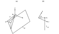
図3(A)(B)は、レーザー距離計測部(距離検出手段の一例)実装例である。 3A and 3B are mounting examples of a laser distance measurement unit (an example of a distance detection unit).
本実施の形態ではキーストーン情報として、レーザー距離計測部100を用いてターゲット面の一直線上にない少なくとも3点までの距離を検出する。レーザー距離計測部100は、例えば図3(A)に示すように、工事支援装置の投射口(投射画像の投射口)90の近くに設けてもよいし、図3(B)に示すように、工事支援装置本体の上部に設けてもよい。
In the present embodiment, as keystone information, the laser
図3(B)のレーザー距離計測部100は、内部に図示しないレーザー光発生部を含み、レーザー光発生部で発生したレーザー光を、ポリゴンミラーで垂直スキャンして、発射窓102から発射する。そして前記照射されたレーザー光のターゲット面に対する反射光を受信窓104の内部に設けられた受光部で受光し、前記各点からの反射光を受光するまでの反射時間に基づき前記各点までの距離を求める。ここでレーザー距離計測部を回転させることにより、レーザー光の水平スキャンも行うことができる。回転するポリゴンミラーは、レーザー光発生部から発射されるレーザー光の向きを変化させて、前記ターゲット面の一直線上にない少なくとも3点に照射する照射角変更手段及び、レーザー光発生部から発射されたレーザー光の光路上に設けられ、レーザー光を反射させるための反射面と、レーザー光の反射方向が変化するように前記反射面の配置角度を制御する反射面制御部として機能する。
The laser
またレーザー距離計測部を回転させる機構は、レーザー光発生部から発射されるレーザー光の向きを変化させて、前記ターゲット面の一直線上にない少なくとも3点に照射する照射角変更手段及びレーザー光発生源の発射方向を変化させる発射方向制御部として機能する。 Further, the mechanism for rotating the laser distance measurement unit changes the direction of the laser beam emitted from the laser beam generation unit, and irradiates at least three points that are not on a straight line of the target surface and generates the laser beam. It functions as a firing direction controller that changes the firing direction of the source.
このように垂直スキャンと水平スキャンによりレーザー光の照射角を変更させて、ターゲット面の一直線上にない少なくとも3点に照射することができる。 In this way, it is possible to irradiate at least three points that are not on a straight line of the target surface by changing the irradiation angle of the laser light by vertical scanning and horizontal scanning.
図4(A)(B)は、レーザー距離計測部の照射角変更手段の他の構成例について説明するための図である。レーザー光発生部で発生したレーザーの発射光120はミラー118に反射してターゲット面210に照射される。そしてターゲット面210に照射したレーザー光はターゲット面210に反射されて、再びミラー118に当たり反射され反射光122となる。ミラー118の近傍には電磁石112があり、電磁石112の強さを制御することにより、ミラー118の動作角を制御できるように構成されている。110は基板116と所定の距離をおいてミラー118を支持する支持棒である。ミラー118と支持棒110はボールジョイントなどで連結するようにしてもよい。電磁石112の強さを変化させて所望の角度にミラー118を傾けることができる。なおミラー118の振動を吸収するために、基板116とミラー118の間にバネ114を挟むようにしてもよい。
4A and 4B are diagrams for explaining another configuration example of the irradiation angle changing means of the laser distance measuring unit. The
図15(A)(B)は、レーザー距離計測部の照射角変更手段の他の構成例について説明するための図である。図15(A)は、レーザー光発光部を含むユニット(以下レーザー発光ユニットという)220の斜視図であり、図15(B)はレーザー発光ユニット220の平面図(上から見た図)である。222は内部のレーザー光発光部で発光されたレーザー光の発射口であり、223はレーザー光の反射光を受光する受光部である。
FIGS. 15A and 15B are diagrams for explaining another configuration example of the irradiation angle changing unit of the laser distance measuring unit. FIG. 15A is a perspective view of a unit (hereinafter referred to as a laser light emitting unit) 220 including a laser light emitting unit, and FIG. 15B is a plan view of the laser light emitting unit 220 (viewed from above). .
図15(A)に示すように、レーザー発光ユニット220は図示しない回転軸(例えばx軸)の回りを回転可能(レーザー光発光口224が222を中心軸とした円周上を移動)に構成し、回転角を制御することによりレーザー発射方向230(レーザー光発射口224の向き)を上下方向228に変化させることができる。
As shown in FIG. 15 (A), the laser
また図15(B)に示すように、レーザー発光ユニット220は図示しない回転軸(例えばz軸)の回りを回転可能(レーザー光発光口224が226を中心軸とした円周上を移動)に構成し、回転角を制御することによりレーザー発射方向230(レーザー光発射口224の向き)左右方向229に変化させることができる。
Further, as shown in FIG. 15B, the laser
例えばレーザー発光ユニット220にステッピングモータなどのアクチュエータを取り付けて2軸で投射方向を変更可能な構成にして、投射方向を変化させる制御を行うことによりレーザー発射方向230を変化させてもよい。
For example, an actuator such as a stepping motor may be attached to the laser
図16は、本実施の形態の投射型表示装置を用いた工事支援処理の流れを示すフローチャートである。 FIG. 16 is a flowchart showing the flow of construction support processing using the projection display device of the present embodiment.
まず作業対象となるターゲット面と投射光の角度によって生じる投射画像のゆがみを補正するために用いるキーストーン情報を取得する(ステップS100)。 First, keystone information used to correct distortion of a projected image caused by an angle between a target surface as a work target and projection light is acquired (step S100).
次にガイドとなる工事支援画像(例えば複数の並行な線を含むガイド画像を含む工事支援画像)を生成する(ステップS200)。 Next, a construction support image serving as a guide (for example, a construction support image including a guide image including a plurality of parallel lines) is generated (step S200).
次に、前記工事支援画像に対してキーストーン情報に基づきキーストーン補正の画像処理を行う(ステップS300)。 Next, image processing for keystone correction is performed on the construction support image based on the keystone information (step S300).
次に、キーストーン補正後の工事支援画像をターゲット面に対し投射する(ステップS400)。 Next, the construction support image after the keystone correction is projected onto the target surface (step S400).
このように本実施の形態では、ターゲット面と工事支援装置の位置関係によって生じる投射画像のゆがみを補正するために用いるキーストーン情報(ターゲット面の傾き、工事支援装置の傾き)を取得して、当該キーストーン情報に基づき工事支援画像に対してキーストーン補正の画像処理を行った後ターゲット面に投射する。従ってターゲット面となる壁の配置が変わっても、その配置に応じたキーストーン補正が行われたガイド画像が表示されるので、正確なガイド表示を行うことができる。 As described above, in the present embodiment, keystone information (target surface inclination, construction support device inclination) used to correct distortion of the projected image caused by the positional relationship between the target surface and the construction support device is acquired, Based on the keystone information, the construction support image is subjected to image processing for keystone correction and then projected onto the target surface. Therefore, even if the arrangement of the wall serving as the target surface is changed, the guide image that has been subjected to the keystone correction corresponding to the arrangement is displayed, so that accurate guide display can be performed.
図17は、本実施の形態のキーストーン情報取得処理の流れを示すフローチャートである。 FIG. 17 is a flowchart showing the flow of keystone information acquisition processing according to this embodiment.
まずレーザー光発生部から発射されるレーザー光の向きを変化させて、前記ターゲット面上の点のうち、一つの直線上にない少なくとも3点を含む複数の点に照射する(ステップS110)。 First, the direction of the laser beam emitted from the laser beam generator is changed to irradiate a plurality of points including at least three points that are not on one straight line among the points on the target surface (step S110).
次にレーザー光のターゲット面に対する反射光を受光する(ステップS120)。 Next, the reflected light of the laser beam with respect to the target surface is received (step S120).
次に複数の点に対してレーザー光を発射してから反射光を受光するまでの反射時間を計測する(ステップS130)。 Next, the reflection time from when the laser beam is emitted to a plurality of points until the reflected light is received is measured (step S130).
次に複数の点に対する反射時間に基づき各点までの距離を求める(ステップS140)。 Next, the distance to each point is calculated based on the reflection times for a plurality of points (step S140).
図5〜図11は、本実施の形態のキーストーン補正処理の一手法について説明するための図である。ターゲット面210の一直線上にない少なくとも3点までの距離を含むキーストーン情報に基づきキーストーン補正を行う場合を例にとり説明する。
5 to 11 are diagrams for explaining one method of the keystone correction process according to the present embodiment. A case where keystone correction is performed based on keystone information including distances up to at least three points that are not on a straight line of the
図5は、ターゲット面Pの一直線上にない3点(基準点)と工事支援装置の代表点(投射レンズの中心点O)を示しており、図6,図7は、図6を別の角度からみた図である。ターゲット面Pの一直線上にない少なくとも3点までの距離は、各点P1,P2,P3と投射レンズの中心点Oまでの距離とする。まずターゲット面210の基準点P1,P2,P3について、投射レンズの中心点Oを原点とする極座標を求める。
FIG. 5 shows three points (reference points) that are not on a straight line of the target surface P and a representative point (center point O of the projection lens) of the construction support device. FIGS. 6 and 7 are different from FIG. It is the figure seen from the angle. The distances to at least three points that are not on a straight line on the target surface P are the distances between the points P1, P2, and P3 and the center point O of the projection lens. First, polar coordinates whose origin is the center point O of the projection lens are obtained for the reference points P1, P2, and P3 of the
P1の極座標は(d1,θ1,λ1)、直交座標に変換するとP1(d1sinθ1cosλ1,d1sinθ1sinλ1,d1cosθ1)となる。di,θi,λiは、それぞれ点Oからの距離、Z軸との角度、X軸との角度を表す。P2,P3の極座標を、それぞれP2(d2,θ2,λ2)、P3(d3,θ3,λ3)とする。P2,P3も、同様に直交座標に変換する。そして、P1,P2,P3を通るターゲット平面Pの式を求める。 The polar coordinates of P1 are (d1, θ1, λ1), and when converted to orthogonal coordinates, P1 (d1sinθ1cosλ1, d1sinθ1sinλ1, d1cosθ1). di, θi, and λi represent the distance from the point O, the angle with the Z axis, and the angle with the X axis, respectively. The polar coordinates of P2 and P3 are P2 (d2, θ2, λ2) and P3 (d3, θ3, λ3), respectively. Similarly, P2 and P3 are converted into orthogonal coordinates. Then, an expression of the target plane P passing through P1, P2, and P3 is obtained.
図7は、点Oを通る光軸を法線とする理想投射面Qとターゲット面Pを示した図である。図8は図7をX軸方向からみた図である。 FIG. 7 is a diagram showing an ideal projection plane Q and a target plane P with the optical axis passing through the point O as a normal line. FIG. 8 is a view of FIG. 7 viewed from the X-axis direction.
レンズの画角をφとして、点Oを通る光軸を法線とする理想投射面Q上の、点Q1,Q2,Q3,Q4を、それぞれ次のように定義する(ここでrは点Oからの距離である)。
Q1(r,(π−φ)/2,(π−φ)/2)
Q2(r,(π−φ)/2,(π+φ)/2)
Q3(r,(π+φ)/2,(π+φ)/2)
Q4(r,(π+φ)/2,(π−φ)/2)
Points Q1, Q2, Q3, and Q4 on the ideal projection plane Q with the angle of view of the lens as φ and the optical axis passing through the point O as normals are defined as follows (where r is the point O): Distance from).
Q1 (r, (π−φ) / 2, (π−φ) / 2)
Q2 (r, (π−φ) / 2, (π + φ) / 2)
Q3 (r, (π + φ) / 2, (π + φ) / 2)
Q4 (r, (π + φ) / 2, (π−φ) / 2)
Q1,Q2,Q3,Q4を、直交座標に変換して、Q1,Q2,Q3を通る面Qの式を求める。線分OQ1,OQ2,OQ3,OQ4と、平面Pとの交点をそれぞれ求め、P1,P2,P3,P4とする。上で求めたP1,P2,P3,P4から、それぞれ面Qに垂線h1,h2,h3,h4を引く。各垂線h1,h2,h3,h4と面Qとの交点をQ1,Q2,Q3,Q4とする。 Q1, Q2, Q3, and Q4 are converted into Cartesian coordinates, and an expression of the plane Q passing through Q1, Q2, and Q3 is obtained. The intersections of the line segments OQ1, OQ2, OQ3, OQ4 and the plane P are obtained, and are defined as P1, P2, P3, P4. Vertical lines h1, h2, h3, and h4 are drawn on the surface Q from P1, P2, P3, and P4 obtained above. Intersections between the vertical lines h1, h2, h3, h4 and the surface Q are defined as Q1, Q2, Q3, Q4.
図9は、ライトバルブの全面を使って全白画像をターゲット面に投射した場合の台形歪みの例(投射装置が光軸を中心に傾いていない場合)である。本来(理想投射面Qに投射した場合)は長方形であるべき映像が、図9に示すように上辺Q2Q1が下辺Q3Q4より短い台形にゆがんでいる。 FIG. 9 is an example of trapezoidal distortion when an entire white image is projected onto the target surface using the entire surface of the light valve (when the projection device is not tilted about the optical axis). Originally (when projected on the ideal projection plane Q), the image that should be rectangular is distorted into a trapezoid whose upper side Q2Q1 is shorter than lower side Q3Q4 as shown in FIG.
そこでターゲット面投射時に長方形の映像となるように、元画像を図10に示すように変形させてから(キーストーン補正を行ってから)、ターゲット面に投射する。四角形Q1Q2Q3Q4を理想投射面Q上で180°回転した図形と相似な図形を、ライトバルブの表示領域に内接するようにして得られる四角形Q1’Q2’Q3’Q4’を、描画領域’とする。光源からの光は、映像信号が表す座標値をQ’上の対応する点にマップして得られる画像で変調される。 Therefore, after the original image is deformed as shown in FIG. 10 (after performing the keystone correction) so that a rectangular image is obtained when the target surface is projected, the image is projected onto the target surface. A quadrangle Q1'Q2'Q3'Q4 'obtained by inscribed a graphic similar to the graphic obtained by rotating the quadrangle Q1Q2Q3Q4 by 180 ° on the ideal projection plane Q inscribed in the display area of the light valve is defined as a drawing area'. The light from the light source is modulated with an image obtained by mapping the coordinate value represented by the video signal to a corresponding point on Q '.
このようにすると図11(A)に示すようにレンズから投射された光学像は、ターゲット面210上に結像するとき、光路長の違いによって生じる台形歪みが補正される(310参照)。
In this way, as shown in FIG. 11A, when the optical image projected from the lens is formed on the
図11(B)は、ライトバルブ330と描画領域Q’の関係を示している。
FIG. 11B shows the relationship between the
図12は、本実施の形態のユーザーインターフェースについて説明するための図である。 FIG. 12 is a diagram for explaining a user interface according to the present embodiment.
ユーザーインターフェースは液晶表示装置400と操作部401〜404等で構成することができる。操作部401〜404は、操作部にもうけられた調整用のつまみ(ユーザーインターフェース)である。401は、左右移動ツマミであり、このつまみ401を回すことにより、垂直線410−1、410−2,・・・を左右に平行移動させることができる。402は、上下移動ツマミであり、このつまみ402を回すことにより、水平線420−1、420−2,・・・を上下に平行移動させることができる。403は、垂直線回転ツマミであり、このつまみ403を回すことにより、垂直線を任意角度に回転させることができる。404は、水平線回転ツマミであり、このつまみ403を回すことにより、水平線を任意角度に回転させることができる。図14は、つまみ404を回して、水平線の角度を変えた時の様子を表す図である。
The user interface can be composed of a liquid
また図14に示すように、ガイドとなる格子(垂直線、水平線)の投射は反転・非反転のいずれにも対応できるようにしてもよい。 Further, as shown in FIG. 14, the projection of the lattice (vertical line, horizontal line) serving as a guide may be able to cope with both inversion and non-inversion.
ユーザーインターフェースの操作部は、上記の操作ツマミ以外に、格子の間隔を入力するキーや、水平線か垂直線のいずれか一方を選択する際に押下するファンクションキーを備えるようにしてもよい。 In addition to the above-described operation knob, the operation unit of the user interface may include a key for inputting a grid interval and a function key to be pressed when selecting either a horizontal line or a vertical line.
また上記ファンクションキーを押しながら1または2を回すと、水平線か垂直線のいずれか一方を上下または左右に平行移動させることができるようにしてもよい。 Further, by turning 1 or 2 while pressing the function key, either one of the horizontal line and the vertical line may be translated up and down or left and right.
また距離センサが検出した距離に基づいて、投射面に描かれる格子の間隔が、ユーザーインターフェースで指定した大きさになるように制御してもよい。また重力センサの出力に基づき、水平・垂直を自動的に補正するようにしてもよい。 Further, based on the distance detected by the distance sensor, the interval of the lattice drawn on the projection surface may be controlled to be the size specified by the user interface. Further, the horizontal and vertical directions may be automatically corrected based on the output of the gravity sensor.
またユーザーインターフェースの液晶表示装置400にタッチパネルを備え、任意の線分(例えば水平線や垂直線)の位置を個別に動かせるようにしてもよい。
Further, the liquid
本発明は、実施の形態で説明した構成と実質的に同一の構成(例えば、機能、方法及び結果が同一の構成、あるいは目的及び効果が同一の構成)を含む。また、本発明は、実施の形態で説明した構成の本質的でない部分を置き換えた構成を含む。また、本発明は、実施の形態で説明した構成と同一の作用効果を奏する構成又は同一の目的を達成することができる構成を含む。また、本発明は、実施の形態で説明した構成に公知技術を付加した構成を含む。 The present invention includes configurations that are substantially the same as the configurations described in the embodiments (for example, configurations that have the same functions, methods, and results, or configurations that have the same objects and effects). In addition, the invention includes a configuration in which a non-essential part of the configuration described in the embodiment is replaced. In addition, the present invention includes a configuration that exhibits the same operational effects as the configuration described in the embodiment or a configuration that can achieve the same object. Further, the invention includes a configuration in which a known technique is added to the configuration described in the embodiment.
1 工事支援装置、20 距離検出部、30 制御部、32 工事支援画像生成部、34 キーストーン補正部、40 投射光学系、50 重力センサ、60 電源部、100 レーザー距離計測部、118 ミラー、210 ターゲット面 DESCRIPTION OF SYMBOLS 1 Construction support apparatus, 20 Distance detection part, 30 Control part, 32 Construction support image generation part, 34 Keystone correction part, 40 Projection optical system, 50 Gravity sensor, 60 Power supply part, 100 Laser distance measurement part, 118 Mirror, 210 Target surface
Claims (7)
ターゲット面と投射光の角度によって生じる投射画像のゆがみを補正するために用いるキーストーン情報を取得するキーストーン情報取得手段と、
所定の工事支援画像を生成する工事支援画像生成手段と、
前記工事支援画像に対してキーストーン情報に基づきキーストーン補正の画像処理を行うキーストーン補正手段と、
キーストーン補正後の工事支援画像をターゲット面に対し投射する画像投射手段と、
を含むことを特徴とする工事支援装置。 A construction support device for projecting and displaying a construction work support image on a target surface to be worked,
Keystone information acquisition means for acquiring keystone information used to correct distortion of the projected image caused by the angle of the target surface and the projection light;
Construction support image generation means for generating a predetermined construction support image;
Keystone correction means for performing image processing for keystone correction based on the keystone information for the construction support image;
Image projection means for projecting the construction support image after the keystone correction to the target surface;
Construction support device characterized by including
前記キーストーン情報取得手段は、
キーストーン情報として、ターゲット面上の点のうち、一つの直線上にない少なくとも3点を含む複数の点と、プロジェクタとの距離をそれぞれ検出する距離検出手段を含み、
前記キーストーン補正手段は、
前記距離を含むキーストーン情報に基づきキーストーン補正を行うことを特徴とする工事支援装置。 In claim 1,
The keystone information acquisition means includes
As the keystone information, including a distance detection means for detecting a distance between each of a plurality of points including at least three points that are not on one straight line among the points on the target surface, and the projector,
The keystone correction means includes
A construction support apparatus that performs keystone correction based on keystone information including the distance.
前記距離検出手段は、
レーザー光発生部と、
レーザー光発生部から発射されるレーザー光の向きを変化させて、前記複数の点に前記レーザー光を照射する照射角変更手段と、
前記レーザー光のターゲット面に対する反射光を受光する受光手段と、
前記複数の点に対して前記レーザー光を発射してから前記反射光を受光するまでの反射時間を計測する反射時間計測手段と、
を含み、前記反射時間に基づき前記距離を求めることを特徴とする工事支援装置。 In claim 2,
The distance detecting means includes
A laser beam generator,
An irradiation angle changing means for changing the direction of the laser light emitted from the laser light generator and irradiating the laser light to the plurality of points,
A light receiving means for receiving the reflected light of the laser beam with respect to the target surface;
A reflection time measuring means for measuring a reflection time from emitting the laser light to the plurality of points until receiving the reflected light;
The construction support apparatus is characterized in that the distance is obtained based on the reflection time.
前記照射角変更手段は、
前記レーザー光発生部から発射された前記レーザー光の光路上に設けられ、前記レーザー光を反射させるための反射面と、前記レーザー光の反射方向が変化するように前記反射面の配置角度を制御する反射面制御部と、を含むことを特徴とする工事支援装置。 In claim 3,
The irradiation angle changing means includes
Provided on the optical path of the laser beam emitted from the laser beam generator, and controls the arrangement angle of the reflection surface so that the reflection surface for reflecting the laser beam and the reflection direction of the laser beam change A construction support device comprising: a reflecting surface control unit.
前記照射角変更手段は、
レーザー光発生部の向きを変化させる発射方向制御部と、を含むことを特徴とする工事支援装置。 In claim 3,
The irradiation angle changing means includes
A construction support apparatus comprising: a launch direction control unit that changes a direction of the laser light generation unit.
前記所定の工事支援画像は、複数の平行な線を含むガイド画像であり、
前記ガイド画像の複数の並行な線の向きおよび線間の幅の少なくとも1つに対する変更情報を受け付けるための変更情報受け付け部を含み、
前記工事支援画像生成手段は、
受け付けた変更情報に基づき複数の並行な線の向き及び線間の幅の少なくとも1つを変更した工事支援画像を生成することを特徴とする工事支援装置。 In any one of Claims 1 thru | or 5,
The predetermined construction support image is a guide image including a plurality of parallel lines,
A change information receiving unit for receiving change information for at least one of a plurality of parallel line directions and a width between lines of the guide image;
The construction support image generation means includes
A construction support apparatus that generates a construction support image in which at least one of a plurality of parallel line orientations and widths between lines is changed based on received change information.
作業対象となるターゲット面と投射光の角度によって生じる投射画像のゆがみを補正するために用いるキーストーン情報を取得するキーストーン情報取得ステップと、
投射型表示装置が、ガイドとなる工事支援画像を生成する工事支援画像生成ステップと、
投射型表示装置が、前記工事支援画像に対してキーストーン情報に基づきキーストーン補正の画像処理を行うキーストーン補正ステップと、
投射型表示装置が、キーストーン補正後の工事支援画像をターゲット面に対し投射する画像投射ステップと、を含み、
キーストーン情報取得ステップは、
レーザー光発生部から発射されるレーザー光の向きを変化させて、前記ターゲット面上の点のうち、一つの直線上にない少なくとも3点を含む複数の点に照射するステップと、
前記レーザー光のターゲット面に対する反射光を受光するステップと、
前記複数の点に対してレーザー光を発射してから反射光を受光するまでの反射時間を計測するステップと、
前記複数の点に対する反射時間に基づき前記各点までの距離を求めるステップと、を含むことを特徴とする工事支援方法。 A construction support method using a projection display device,
A keystone information acquisition step for acquiring keystone information used to correct distortion of the projected image caused by the angle of the target surface to be worked and the projection light;
A construction support image generation step in which the projection display device generates a construction support image to be a guide;
A keystone correction step in which the projection display device performs image processing for keystone correction based on the keystone information for the construction support image;
An image projection step for projecting the construction support image after the keystone correction to the target surface, the projection display device,
Keystone information acquisition step
Irradiating a plurality of points including at least three points not on one straight line among the points on the target surface by changing the direction of the laser light emitted from the laser light generation unit;
Receiving reflected light of the laser beam with respect to the target surface;
Measuring a reflection time from emitting laser light to the plurality of points until receiving reflected light; and
Obtaining a distance to each of the points based on reflection times for the plurality of points.
Priority Applications (1)
| Application Number | Priority Date | Filing Date | Title |
|---|---|---|---|
| JP2007065205A JP2008224516A (en) | 2007-03-14 | 2007-03-14 | Construction support device and construction support method |
Applications Claiming Priority (1)
| Application Number | Priority Date | Filing Date | Title |
|---|---|---|---|
| JP2007065205A JP2008224516A (en) | 2007-03-14 | 2007-03-14 | Construction support device and construction support method |
Publications (1)
| Publication Number | Publication Date |
|---|---|
| JP2008224516A true JP2008224516A (en) | 2008-09-25 |
Family
ID=39843315
Family Applications (1)
| Application Number | Title | Priority Date | Filing Date |
|---|---|---|---|
| JP2007065205A Withdrawn JP2008224516A (en) | 2007-03-14 | 2007-03-14 | Construction support device and construction support method |
Country Status (1)
| Country | Link |
|---|---|
| JP (1) | JP2008224516A (en) |
Cited By (16)
| Publication number | Priority date | Publication date | Assignee | Title |
|---|---|---|---|---|
| JP2013539541A (en) * | 2010-09-08 | 2013-10-24 | ファロ テクノロジーズ インコーポレーテッド | Laser scanner or laser tracking device having a projector |
| KR20140100105A (en) * | 2013-02-05 | 2014-08-14 | 엘지전자 주식회사 | Projector and controlling method thereof |
| JP2014199257A (en) * | 2010-01-20 | 2014-10-23 | ファロ テクノロジーズ インコーポレーテッド | Articulated arm coordinate measuring machine |
| WO2016031504A1 (en) * | 2014-08-28 | 2016-03-03 | 株式会社トプコン | Survey information marking device and survey information marking method |
| JP2016133757A (en) * | 2015-01-22 | 2016-07-25 | セイコーエプソン株式会社 | projector |
| US9607239B2 (en) | 2010-01-20 | 2017-03-28 | Faro Technologies, Inc. | Articulated arm coordinate measurement machine having a 2D camera and method of obtaining 3D representations |
| US9628775B2 (en) | 2010-01-20 | 2017-04-18 | Faro Technologies, Inc. | Articulated arm coordinate measurement machine having a 2D camera and method of obtaining 3D representations |
| JP2017218792A (en) * | 2016-06-07 | 2017-12-14 | 清水建設株式会社 | Construction management apparatus and construction management method |
| US10281259B2 (en) | 2010-01-20 | 2019-05-07 | Faro Technologies, Inc. | Articulated arm coordinate measurement machine that uses a 2D camera to determine 3D coordinates of smoothly continuous edge features |
| JP2021034957A (en) * | 2019-08-28 | 2021-03-01 | パナソニックIpマネジメント株式会社 | Projection system and projection method |
| JPWO2021039313A1 (en) * | 2019-08-28 | 2021-03-04 | ||
| CN113632454A (en) * | 2019-03-29 | 2021-11-09 | 松下知识产权经营株式会社 | Projection system, projection device and projection method |
| JP2022515716A (en) * | 2018-11-29 | 2022-02-22 | トゥアン チャールズ ハ,ヒエウ | Projection device for displaying construction plans |
| JP2022100963A (en) * | 2020-12-24 | 2022-07-06 | 大成建設株式会社 | Design drawing projection system and design drawing projection method |
| JP2023148007A (en) * | 2022-03-30 | 2023-10-13 | 株式会社竹中工務店 | Display system and display program |
| JPWO2024038610A1 (en) * | 2022-08-19 | 2024-02-22 |
-
2007
- 2007-03-14 JP JP2007065205A patent/JP2008224516A/en not_active Withdrawn
Cited By (31)
| Publication number | Priority date | Publication date | Assignee | Title |
|---|---|---|---|---|
| US10060722B2 (en) | 2010-01-20 | 2018-08-28 | Faro Technologies, Inc. | Articulated arm coordinate measurement machine having a 2D camera and method of obtaining 3D representations |
| JP2014199257A (en) * | 2010-01-20 | 2014-10-23 | ファロ テクノロジーズ インコーポレーテッド | Articulated arm coordinate measuring machine |
| US9607239B2 (en) | 2010-01-20 | 2017-03-28 | Faro Technologies, Inc. | Articulated arm coordinate measurement machine having a 2D camera and method of obtaining 3D representations |
| US9628775B2 (en) | 2010-01-20 | 2017-04-18 | Faro Technologies, Inc. | Articulated arm coordinate measurement machine having a 2D camera and method of obtaining 3D representations |
| US10281259B2 (en) | 2010-01-20 | 2019-05-07 | Faro Technologies, Inc. | Articulated arm coordinate measurement machine that uses a 2D camera to determine 3D coordinates of smoothly continuous edge features |
| JP2013539541A (en) * | 2010-09-08 | 2013-10-24 | ファロ テクノロジーズ インコーポレーテッド | Laser scanner or laser tracking device having a projector |
| KR20140100105A (en) * | 2013-02-05 | 2014-08-14 | 엘지전자 주식회사 | Projector and controlling method thereof |
| KR102124475B1 (en) * | 2013-02-05 | 2020-06-19 | 엘지전자 주식회사 | Projector and controlling method thereof |
| JPWO2016031504A1 (en) * | 2014-08-28 | 2017-05-25 | 株式会社トプコン | Surveying information marking device, surveying information marking method |
| US9776320B2 (en) | 2014-08-28 | 2017-10-03 | Kabushiki Kaisha Topcon | Measurement and installation data indicating apparatus and measurement and installation data indicating method |
| CN106716061A (en) * | 2014-08-28 | 2017-05-24 | 株式会社拓普康 | Survey information marking device and survey information marking method |
| WO2016031504A1 (en) * | 2014-08-28 | 2016-03-03 | 株式会社トプコン | Survey information marking device and survey information marking method |
| JP2016133757A (en) * | 2015-01-22 | 2016-07-25 | セイコーエプソン株式会社 | projector |
| JP2017218792A (en) * | 2016-06-07 | 2017-12-14 | 清水建設株式会社 | Construction management apparatus and construction management method |
| US12309535B2 (en) | 2018-11-29 | 2025-05-20 | 9373-6817 Quebec Inc. | Projection device for displaying construction plans |
| JP2022515716A (en) * | 2018-11-29 | 2022-02-22 | トゥアン チャールズ ハ,ヒエウ | Projection device for displaying construction plans |
| US11937024B2 (en) | 2019-03-29 | 2024-03-19 | Panasonic Intellectual Property Management Co., Ltd. | Projection system, projection device and projection method |
| CN113632454B (en) * | 2019-03-29 | 2024-08-27 | 松下知识产权经营株式会社 | Projection system, projection device and projection method |
| CN113632454A (en) * | 2019-03-29 | 2021-11-09 | 松下知识产权经营株式会社 | Projection system, projection device and projection method |
| JP2021034957A (en) * | 2019-08-28 | 2021-03-01 | パナソニックIpマネジメント株式会社 | Projection system and projection method |
| US20220276548A1 (en) * | 2019-08-28 | 2022-09-01 | Panasonic Intellectual Property Management Co., Ltd. | Projection method, projection device, and projection system |
| JP7304591B2 (en) | 2019-08-28 | 2023-07-07 | パナソニックIpマネジメント株式会社 | PROJECTION METHOD, PROJECTION APPARATUS, AND PROJECTION SYSTEM |
| US11803109B2 (en) | 2019-08-28 | 2023-10-31 | Panasonic Intellectual Property Management Co., Ltd. | Projection method, projection device, and projection system |
| JP7417838B2 (en) | 2019-08-28 | 2024-01-19 | パナソニックIpマネジメント株式会社 | Projection system and projection method |
| CN114342363A (en) * | 2019-08-28 | 2022-04-12 | 松下知识产权经营株式会社 | Projection method, projection device and projection system |
| CN114342363B (en) * | 2019-08-28 | 2024-07-19 | 松下知识产权经营株式会社 | Projection method, projection device and projection system |
| WO2021039313A1 (en) * | 2019-08-28 | 2021-03-04 | パナソニックIpマネジメント株式会社 | Projection method, projection device, and projection system |
| JPWO2021039313A1 (en) * | 2019-08-28 | 2021-03-04 | ||
| JP2022100963A (en) * | 2020-12-24 | 2022-07-06 | 大成建設株式会社 | Design drawing projection system and design drawing projection method |
| JP2023148007A (en) * | 2022-03-30 | 2023-10-13 | 株式会社竹中工務店 | Display system and display program |
| JPWO2024038610A1 (en) * | 2022-08-19 | 2024-02-22 |
Similar Documents
| Publication | Publication Date | Title |
|---|---|---|
| JP2008224516A (en) | Construction support device and construction support method | |
| JP6464213B2 (en) | Laser processing system having laser processing head and imaging device | |
| EP3187824B1 (en) | Measurement and installation data indicating apparatus and method | |
| US11725939B2 (en) | System and method for controlling a light projector in a construction site | |
| WO2018050125A1 (en) | Hand-held tool system | |
| JP7587460B2 (en) | 3D shape measuring device | |
| JP6746860B2 (en) | Marking support device and marking support method | |
| JP2009098046A (en) | Three-dimensional shape measuring instrument | |
| JP5234254B2 (en) | Laser radar and laser radar calibration method | |
| JP2024169464A (en) | Optical axis adjustment device | |
| JP2003220485A (en) | Laser marking system and method for regulation of guide image projection position thereof | |
| JP7304591B2 (en) | PROJECTION METHOD, PROJECTION APPARATUS, AND PROJECTION SYSTEM | |
| JP5320693B2 (en) | Image processing device, projector | |
| JP2010086928A (en) | Illuminating device | |
| JP7587461B2 (en) | 3D shape measuring device | |
| WO2007013607A1 (en) | Cross-section image display, cross-section image display method, and cross-section image display program | |
| JP2005345415A (en) | Marking device, and leveling method in marking device | |
| JP2012213042A (en) | Mobile setting terminal and monitoring system | |
| JP6165069B2 (en) | Crease work support system, crease work method and machined parts | |
| WO2020071167A1 (en) | Optical axis adjustment apparatus | |
| CN119011792A (en) | Projection interaction method based on infrared light spots, projection equipment and storage medium | |
| JP2012199772A (en) | Projector and projector installation method | |
| JP2020056891A (en) | Control method and optical apparatus | |
| JP4411564B2 (en) | Inking device | |
| JP2020056663A (en) | Control method and distance measuring device |
Legal Events
| Date | Code | Title | Description |
|---|---|---|---|
| RD04 | Notification of resignation of power of attorney |
Free format text: JAPANESE INTERMEDIATE CODE: A7424 Effective date: 20080702 |
|
| A300 | Application deemed to be withdrawn because no request for examination was validly filed |
Free format text: JAPANESE INTERMEDIATE CODE: A300 Effective date: 20100601 |