JP5320693B2 - Image processing device, projector - Google Patents
Image processing device, projector Download PDFInfo
- Publication number
- JP5320693B2 JP5320693B2 JP2007164970A JP2007164970A JP5320693B2 JP 5320693 B2 JP5320693 B2 JP 5320693B2 JP 2007164970 A JP2007164970 A JP 2007164970A JP 2007164970 A JP2007164970 A JP 2007164970A JP 5320693 B2 JP5320693 B2 JP 5320693B2
- Authority
- JP
- Japan
- Prior art keywords
- angle parameter
- correction
- correction angle
- projector
- image
- Prior art date
- Legal status (The legal status is an assumption and is not a legal conclusion. Google has not performed a legal analysis and makes no representation as to the accuracy of the status listed.)
- Expired - Fee Related
Links
- 230000003287 optical effect Effects 0.000 claims description 31
- 238000004364 calculation method Methods 0.000 claims description 27
- 238000009434 installation Methods 0.000 claims description 14
- 239000011159 matrix material Substances 0.000 claims description 14
- 238000006243 chemical reaction Methods 0.000 claims description 5
- 238000004590 computer program Methods 0.000 claims description 5
- 238000003672 processing method Methods 0.000 claims description 5
- 239000004973 liquid crystal related substance Substances 0.000 description 32
- 230000015572 biosynthetic process Effects 0.000 description 13
- 238000000034 method Methods 0.000 description 10
- 230000008569 process Effects 0.000 description 8
- 238000010586 diagram Methods 0.000 description 7
- 230000009466 transformation Effects 0.000 description 6
- 230000008859 change Effects 0.000 description 5
- 238000005286 illumination Methods 0.000 description 4
- 230000004044 response Effects 0.000 description 4
- 230000008901 benefit Effects 0.000 description 1
- 238000005401 electroluminescence Methods 0.000 description 1
Images


Landscapes
- Controls And Circuits For Display Device (AREA)
- Projection Apparatus (AREA)
- Image Processing (AREA)
- Transforming Electric Information Into Light Information (AREA)
- Control Of Indicators Other Than Cathode Ray Tubes (AREA)
Description
本発明は、プロジェクタのための画像処理に関し、特に、投写面に表示される画像の歪み補正技術に関する。 The present invention relates to image processing for a projector, and more particularly to a technique for correcting distortion of an image displayed on a projection surface.
プロジェクタは、通常、あおり投写によって投写面に画像を表示する。あおり投写とは。プロジェクタの光源光軸が投写面に対して垂直に交わらない場合の投写手法を意味する。あおり投写によって投写面に表示された画像は歪んで表示されるため、プロジェクタには、歪みを抑制した画像を投写面に表示するための補正機能が設けられている。このような補正機能は、例えば、プロジェクタの投写角度に関する角度パラメータを用いて、内部に設けられた液晶ライトバルブなどの画像形成部に歪んだ画像を形成することにより、投写面に表示される画像の歪みを補正する。 A projector normally displays an image on a projection surface by tilt projection. What is tilt projection? This means a projection method when the light source optical axes of the projector do not intersect perpendicularly to the projection plane. Since an image displayed on the projection plane by tilt projection is displayed with distortion, the projector is provided with a correction function for displaying an image with suppressed distortion on the projection plane. Such a correction function is, for example, an image displayed on the projection surface by forming a distorted image on an image forming unit such as a liquid crystal light valve provided inside using an angle parameter related to the projection angle of the projector. Correct distortion.
画像の歪み補正に用いられる角度パラメータには、ピッチ角、ヨー角、チルト角の3種類がある。ピッチ角は、プロジェクタを縦方向にあおった場合の回転角度で表され、ヨー角は、プロジェクタを横方向にあおった場合の、スクリーン法線nと光源光軸LAとの間の角度で表され、チルト角は、プロジェクタの光源光軸を中心とする回転角度により表される。ピッチ角の調整により投写面に表示された歪み画像の縦方向の辺の歪みが補正され、ヨー角の調整により投写面に表示された歪み画像の横方向の辺の歪みが補正され、チルト角の調整により、投写面に表示された画像の、水平面に対する傾きが補正される。チルト角を補正すると、投写面に表示されている画像の形状に新たな歪みが発生する。そのため、ピッチ角およびヨー角の補正前にチルト角を補正する必要がある。 There are three types of angle parameters used for image distortion correction: pitch angle, yaw angle, and tilt angle. The pitch angle is expressed as a rotation angle when the projector is raised in the vertical direction, and the yaw angle is expressed as an angle between the screen normal n and the light source optical axis LA when the projector is raised in the horizontal direction. The tilt angle is represented by a rotation angle around the light source optical axis of the projector. By adjusting the pitch angle, distortion in the vertical direction of the distorted image displayed on the projection surface is corrected, and by adjusting the yaw angle, distortion in the horizontal direction of the distorted image displayed on the projection surface is corrected, and the tilt angle is corrected. By the adjustment, the inclination of the image displayed on the projection plane with respect to the horizontal plane is corrected. When the tilt angle is corrected, new distortion occurs in the shape of the image displayed on the projection surface. Therefore, it is necessary to correct the tilt angle before correcting the pitch angle and yaw angle.
しかしながら、投写面に表示されている画像の形状に台形歪みの生じている状態で、チルト角を補正しなければならず、投写面に表示されている画像の形状を補正の目安とすることが困難であり、補正の精度が低下する。また、チルト角補正後にピッチ角およびヨー角を補正して画像の台形歪みを補正しても、投写面に表示された画像が水平面に対して傾いていることがある。このため、ユーザは、ピッチ角およびヨー角の補正後に、再度チルト角を補正しなければならないことがあり、煩雑である。 However, the tilt angle must be corrected in a state where the image displayed on the projection plane has a trapezoidal distortion, and the shape of the image displayed on the projection plane may be used as a guideline for correction. It is difficult and the accuracy of correction is reduced. Further, even if the pitch angle and the yaw angle are corrected after correcting the tilt angle to correct the trapezoidal distortion of the image, the image displayed on the projection plane may be inclined with respect to the horizontal plane. For this reason, the user may have to correct the tilt angle again after correcting the pitch angle and yaw angle, which is complicated.
本発明は上述の課題に鑑みてなされたものであり、多軸の回転角度を用いて投写面に表示された画像の歪みを補正するプロジェクタにおける歪み補正の精度向上およびプロジェクタを利用するユーザの利便性の向上を目的とする。 The present invention has been made in view of the above-described problems, and improves the accuracy of distortion correction in a projector that corrects distortion of an image displayed on a projection plane using a multi-axis rotation angle, and is convenient for a user who uses the projector. The purpose is to improve performance.
本発明は、上述の課題の少なくとも一部を解決するためになされたものであり、以下の形態または適用例として実現することが可能である。
[形態1] 画像データを用いて投写面に表示すべき画像を形成する画像形成部を備えるプロジェクタに用いられる画像処理装置であって、
前記プロジェクタの設置面に対する前記プロジェクタの垂直方向の投写角度に関する第1の補正角度パラメータ、前記設置面に対する前記プロジェクタの水平方向の投写角度に関する第2の補正角度パラメータ、および、前記プロジェクタの光軸に対する前記プロジェクタの回転角度に関する第3の補正角度パラメータと、を入力する入力手段と、
前記入力された第1の補正角度パラメータおよび前記第2の補正角度パラメータを用いて、前記投写面に対して垂直な直線である投写面法線を算出する投写面法線算出手段と、
前記第3の補正角度パラメータを、前記算出された投写面法線を回転軸とする前記プロジェクタの回転角度に変換する変換手段と、
前記第1の補正角度パラメータ、前記第2の補正角度パラメータおよび前記変換された第3の補正角度パラメータを用いて、原画像データから、前記投写面に表示される表示画像の歪みを補正した補正画像データを生成する補正画像データ生成手段と、を備え、
前記入力手段は、前記第3の補正角度パラメータの入力前に、前記投写面に画像を表示するための表示領域の形状を略矩形とするための、前記第1の補正角度パラメータおよび前記第2の補正角度パラメータを入力し、かつ、前記投写面法線の算出後に前記第3の補正角度パラメータを入力する画像処理装置。
SUMMARY An advantage of some aspects of the invention is to solve at least a part of the problems described above, and the invention can be implemented as the following forms or application examples.
[Mode 1] An image processing apparatus used in a projector including an image forming unit that forms an image to be displayed on a projection surface using image data,
A first correction angle parameter related to a vertical projection angle of the projector relative to the installation surface of the projector; a second correction angle parameter related to a horizontal projection angle of the projector relative to the installation surface; and an optical axis of the projector Input means for inputting a third correction angle parameter related to the rotation angle of the projector;
A projection plane normal calculating means for calculating a projection plane normal that is a straight line perpendicular to the projection plane, using the input first correction angle parameter and the second correction angle parameter;
Conversion means for converting the third correction angle parameter into a rotation angle of the projector with the calculated projection plane normal as a rotation axis;
Correction using the first correction angle parameter, the second correction angle parameter, and the converted third correction angle parameter to correct distortion of the display image displayed on the projection plane from the original image data Corrected image data generation means for generating image data,
The input means includes the first correction angle parameter and the second correction parameter for making the shape of a display area for displaying an image on the projection plane substantially rectangular before inputting the third correction angle parameter. An image processing apparatus that inputs the third correction angle parameter after the calculation of the projection plane normal.
[適用例1]
本発明の適用例1は、画像データを用いて投写面に表示すべき画像を形成する画像形成部を備えるプロジェクタに用いられる画像処理装置を提供する。適用例1の画像処理装置は、前記プロジェクタの設置面に対する前記プロジェクタの垂直方向の投写角度に関する第1の補正角度パラメータ、前記設置面に対する前記プロジェクタの水平方向の投写角度に関する第2の補正角度パラメータ、および、前記プロジェクタの光軸に対する前記プロジェクタの回転角度に関する第3の補正角度パラメータと、を入力する入力手段と、前記入力された第1の補正角度パラメータおよび前記第2の補正角度パラメータを用いて、前記投写面に対して垂直な直線である投写面法線を算出する投写面法線算出手段と、前記第3の補正角度パラメータを、前記算出された投写面法線を回転軸とする回転角度に変換する変換手段と、前記第1の補正角度パラメータ、前記第2の補正角度パラメータおよび前記変換された第3の補正角度パラメータを用いて、原画像データから、前記投写面に表示される表示画像の歪みを補正した補正画像データを生成する補正画像データ生成手段と、を備える。
[Application Example 1]
Application Example 1 of the present invention provides an image processing apparatus used in a projector including an image forming unit that forms an image to be displayed on a projection surface using image data. The image processing apparatus of Application Example 1 includes a first correction angle parameter related to a projection angle in the vertical direction of the projector with respect to the installation surface of the projector, and a second correction angle parameter related to a projection angle in the horizontal direction of the projector relative to the installation surface And an input means for inputting a third correction angle parameter relating to the rotation angle of the projector with respect to the optical axis of the projector, and using the input first correction angle parameter and the second correction angle parameter. And a projection plane normal calculating means for calculating a projection plane normal which is a straight line perpendicular to the projection plane, and the third correction angle parameter is the rotation axis of the calculated projection plane normal. Conversion means for converting into a rotation angle; the first correction angle parameter; the second correction angle parameter; Using the third correction angle parameters, from the original image data, and a corrected image data generating means for generating corrected image data by correcting the distortion of the display image displayed on the projection plane.
適用例1の画像処理装置によれば、投写面に表示すべき画像の補正時に、投写面法線を回転軸として回転させた補正画像データを生成できる。従って、投写面とプロジェクタとの相対的な位置関係の変化を抑制できるため、回転歪みを補正する場合に、第1の補正角度パラメータおよび第2の補正角度パラメータを維持した状態で行うことができる。よって、画像の補正形状について新たな台形歪みの発生を抑制することができ、歪み補正の精度を向上できる。 According to the image processing apparatus of Application Example 1, when correcting an image to be displayed on the projection plane, it is possible to generate corrected image data that is rotated about the projection plane normal line as a rotation axis. Therefore, since the change in the relative positional relationship between the projection plane and the projector can be suppressed, the rotational distortion can be corrected while maintaining the first correction angle parameter and the second correction angle parameter. . Therefore, generation of a new trapezoidal distortion can be suppressed for the corrected shape of the image, and the accuracy of distortion correction can be improved.
請求項1記載の画像処理装置において、前記入力手段は、前記第3の補正角度パラメータの入力前に、前記投写面に画像を表示するための表示領域の形状を略矩形とするために、前記第1の補正角度パラメータおよび前記第2の補正角度パラメータを入力する。
2. The image processing apparatus according to
適用例1の画像処理装置によれば、投写面に表示されている画像の形状を略矩形とした後に、投写面法線を回転軸として画像を回転させて、投写面の水平垂直方向に対する表示画像の形状の歪みを補正できる。従って、略矩形とされた表示画像において新たな台形歪みの発生を抑制でき、効率的に歪みを補正できる。 According to the image processing apparatus of Application Example 1, after the image displayed on the projection plane is made substantially rectangular, the image is rotated with the projection plane normal as the rotation axis, and the projection plane is displayed in the horizontal and vertical directions. Image shape distortion can be corrected. Therefore, the generation of a new trapezoidal distortion can be suppressed in the display image having a substantially rectangular shape, and the distortion can be corrected efficiently.
適用例1の画像処理装置において、前記入力手段は、前記第2の補正角度パラメータの入力前に前記第1の補正角度パラメータを入力し、前記補正画像データ生成手段は、前記第1の補正角度パラメータ、前記第2の補正角度パラメータおよび前記第3の補正角度パラメータを、入力された順番で用いた式1により表される回転行列Rに従って補正画像データを生成する。

適用例1の画像処理装置によれば、第1の補正角度パラメータを用いた補正結果を第2の補正角度パラメータを用いた補正に利用できるため、効率的に補正処理を行える。また、第1の補正角度パラメータおよび第2の補正角度パラメータを用いた補正により表示領域を矩形とした後に第3の補正角度パラメータを用いて表示領域を投写面上で回転させることができる。よって、表示領域に新たな歪みの発生を抑制表示領域の歪み補正を行える。 According to the image processing apparatus of Application Example 1, since the correction result using the first correction angle parameter can be used for correction using the second correction angle parameter, the correction process can be performed efficiently. In addition, the display area can be rotated on the projection plane using the third correction angle parameter after making the display area rectangular by correction using the first correction angle parameter and the second correction angle parameter. Therefore, generation of new distortion in the display area can be suppressed, and distortion correction in the display area can be performed.
適用例1の画像処理装置において、更に、前記第1の補正角度パラメータ、前記第2の補正角度パラメータ、前記第3の補正角度パラメータの順番で、前記各補正角度パラメータをユーザに入力させるための角度パラメータ入力画面を前記投写面に表示する表示制御手段を備える。 In the image processing apparatus according to Application Example 1, the correction angle parameter is further input to the user in the order of the first correction angle parameter, the second correction angle parameter, and the third correction angle parameter. Display control means for displaying an angle parameter input screen on the projection plane is provided.
適用例1の画像処理装置によれば、第1の補正角度パラメータ、前記第2の補正角度パラメータ、前記第3の補正角度パラメータの順番で補正角度パラメータを入力させることができるため、効率的に補正処理を行える。 According to the image processing apparatus of the application example 1, the correction angle parameter can be input in the order of the first correction angle parameter, the second correction angle parameter, and the third correction angle parameter. Correction processing can be performed.
[適用例2]
本発明の適用例2は、プロジェクタを提供する。適用例2のプロジェクタは、適用例1の画像処理装置と、光源と、前記光源からの射出光と、前記画像処理装置から入力された前記補正画像データとを用いて、前記投写面に表示すべき画像を形成する画像形成部と、
前記画像形成部から出力された射出光を投写面に投写する投写光学系と、を備える。
[Application Example 2]
Application Example 2 of the present invention provides a projector. The projector of application example 2 displays the image on the projection plane using the image processing apparatus of application example 1, the light source, the light emitted from the light source, and the corrected image data input from the image processing apparatus. An image forming unit for forming a power image;
A projection optical system that projects the emitted light output from the image forming unit onto a projection surface.
適用例2のプロジェクタによれば、スクリーン法線を回転軸とする回転角を用いて投写面に表示される画像の歪みを補正できる。従って、補正形状の計算時に、補正形状における新たな歪みの発生を抑制できる。よって、効率的に歪み補正を行うことができる。 According to the projector of Application Example 2, it is possible to correct distortion of an image displayed on the projection plane using a rotation angle with the screen normal as a rotation axis. Therefore, the generation of new distortion in the corrected shape can be suppressed when calculating the corrected shape. Therefore, distortion correction can be performed efficiently.
本発明において、上述した種々の態様は、適宜、組み合わせたり、一部を省略したりして適用することができる。本発明は、上述した画像処理装置としての構成の他に、画像処理装置による画像処理方法、画像処理装置に画像処理を実行させるためのコンピュータプログラム、かかるコンピュータプログラムをコンピュータ読み取り可能に記録した記録媒体等としても構成できる。いずれの構成においても、上述した各態様を適宜適用可能である。コンピュータが読み取り可能な記録媒体としては、例えば、フレキシブルディスクや、CD−ROM、DVD−ROM、光磁気ディスク、ICカード、ハードディスク等種々の媒体を利用することが可能である。 In the present invention, the various aspects described above can be applied by appropriately combining or omitting some of them. In addition to the configuration as the image processing apparatus described above, the present invention provides an image processing method by the image processing apparatus, a computer program for causing the image processing apparatus to perform image processing, and a recording medium on which the computer program is recorded in a computer-readable manner. Etc. can also be configured. In any configuration, the above-described aspects can be appropriately applied. As a computer-readable recording medium, various media such as a flexible disk, a CD-ROM, a DVD-ROM, a magneto-optical disk, an IC card, and a hard disk can be used.
A1−1.機能ブロック:
図1は、実施例におけるプロジェクタPJの構成を例示するブロック図である。プロジェクタPJは、照明光学系100と、液晶ライトバルブ300と、投写光学系340とを備える。図1において、各光学系は簡略に示されている。また、プロジェクタPJは、光源ランプ駆動部110、液晶ライトバルブ駆動部310、投写光学系調整部350、CPU400、画像入力部410、画像処理部420、操作部510を備える。CPU400は、プロジェクタPJ全体の動作を制御する。
A1-1. Function block:
FIG. 1 is a block diagram illustrating the configuration of the projector PJ in the embodiment. The projector PJ includes an illumination
光源ランプ駆動部110は、照明光学系100に含まれる光源ランプを駆動する。液晶ライトバルブ駆動部310は、画像処理部420から与えられる画像データに従って、液晶ライトバルブ300を駆動する。
The light source
操作部510は、ユーザからの入力に応じて、CPU400に種々の処理を実行させる。例えば、ユーザは、操作部510を介して、画像の歪み補正処理に用いられる角度パラメータを入力したり、スクリーンSCに投写される画像のコントラストを調整したりできる。実施例において、角度パラメータは、プロジェクタPJと投写面との間の角度(投写角度)に関する情報である、角度パラメータθ、φ、ψの3種類が含まれる。詳細は後述する。
The
投写光学系調整部350は、投写光学系340の位置を調整する。具体的には、投写光学系調整部350は、光源光軸LAに平行な方向に向けて、投写光学系340に含まれるレンズを移動させたり、シフト位置を調整したりする。なお、光源光軸は照明光学系100から射出される光の中心軸を意味しており、液晶ライトバルブ300がスクリーンSCに投写する画像の中心を通る。
The projection optical
画像入力部410は、外部から与えられた画像データを画像処理部420に受け渡す。例えば、画像入力部410は、メモリカードMC内に格納されている画像データを読み出し、かかる画像データを画像処理部420に受け渡す。
The
画像処理部420は、画像入力部410から受け渡された画像データを処理して、入力画像データから補正画像データを生成し、補正画像データを液晶ライトバルブ駆動部310へ受け渡す。あおり投写によってスクリーンSC上に画像が表示される場合、液晶ライトバルブ300に歪みのない矩形画像が形成されると、スクリーンSC上に表示される画像は、略台形状に歪む。逆に、液晶ライトバルブ300に略台形上に歪んだ画像を形成すれば、スクリーンSC上に歪みのない画像を表示可能である。以降、実施例では、液晶ライトバルブ300に形成する歪んだ画像を「歪み画像」と呼び、歪み画像の外形形状を「歪み画像の形状」と呼ぶ。歪み補正部430は、入力画像データを補正して歪み画像を表す補正画像データを生成する。補正画像データに従って、液晶ライトバルブ300に歪み画像が形成されると、スクリーンSCには矩形の画像が表示される。
The
具体的には、画像処理部420は、歪み補正部430として機能するコンピュータプログラムを備えており、歪み補正部430は、補正形状計算モジュール432と、補正実行モジュール434と、を備える。
Specifically, the
補正形状計算モジュール432は、操作部510を介して入力された角度パラメータθ、φ、ψを用いて、投写面に表示される画像の形状について、矩形かつ係る矩形の対辺がそれぞれスクリーンSCの水平方向および垂直方向に略平行となるように、液晶ライトバルブ300に形成される画像の補正形状を計算する。具体的には、補正形状計算モジュール432は、入力された角度パラメータを用いてスクリーンに垂直な直線であるスクリーン法線を算出し、光軸を回転軸とするプロジェクタの横転角度に関する角度パラメータψを、スクリーン法線を回転軸とする回転角度に変換し、これを用いて投写面に表示される画像の補正形状を計算する。実施例において、補正形状の計算とは、後に説明する回転行列の算出を含む。補正形状計算モジュール432は、特許請求の範囲における「投写面法線算出手段」および「変換手段」に当たる。以降、実施例では、液晶ライトバルブにおける、画像が形成される領域を「形成領域」と呼び、投写面における、画像が表示される領域を「表示領域」と呼ぶ。
The correction
補正実行モジュール434は、補正形状計算モジュール432によって計算された形成領域の補正形状に基づき、入力画像データから、液晶ライトバルブ300に歪み画像を形成するための補正画像データを生成し、液晶ライトバルブ300に入力する。補正実行モジュール434は、特許請求の範囲の「補正画像データ生成手段」に当たる。
The
以上のような構成を備えることにより、プロジェクタPJは、ユーザから入力された角度パラメータを用いて計算した画像の補正形状に基づき、液晶ライトバルブ300に形成すべき歪み画像を表す補正画像データを生成して、投写面に表示されている画像の歪みを補正する。
With the above-described configuration, the projector PJ generates corrected image data representing a distortion image to be formed on the liquid crystal
A2.スクリーン法線:
A2ー1.角度パラメータ:
図2(a)〜(c)は、実施例におけるプロジェクタとスクリーンSCとの間の角度(投写角度)について説明する説明図である。図2(a)〜(c)において、プロジェクタとスクリーンSCとが設置されている空間をxyz座標系で示す。図2(a)に示すように、実施例では、プロジェクタPJは、x−z平面に平行な面上に設置されており、スクリーンSCはx−y平面に平行な平面である。図2(b)および図2(c)に示すように、x軸は、プロジェクタの設置面に対して水平方向(プロジェクタの左右方向)に伸びた直線であり、y軸は、設置面の垂直方向(プロジェクタの上下方向)に伸びた直線であり、z軸は、プロジェクタPJの前後方向に伸びた直線(x軸およびy軸に垂直な直線)である。各軸は、それぞれ、右側、上側、前側がプラスと規定されている。
A2. Screen normal:
A2-1. Angle parameter:
FIGS. 2A to 2C are explanatory diagrams for explaining an angle (projection angle) between the projector and the screen SC in the embodiment. 2A to 2C, a space where the projector and the screen SC are installed is shown in an xyz coordinate system. As shown in FIG. 2A, in the embodiment, the projector PJ is installed on a plane parallel to the xz plane, and the screen SC is a plane parallel to the xy plane. As shown in FIGS. 2B and 2C, the x-axis is a straight line extending in the horizontal direction (left-right direction of the projector) with respect to the projector installation surface, and the y-axis is perpendicular to the installation surface. The z-axis is a straight line extending in the front-rear direction of the projector PJ (a straight line perpendicular to the x-axis and the y-axis). Each axis is defined as positive on the right side, upper side, and front side.
投写角度に関する角度情報としては、ピッチ角θ、ヨー角φ、ロール角ψの3種類がある。ピッチ角は、図2(b)に示すように、プロジェクタPJの設置面に対してプロジェクタPJを上下方向に回転させた場合の接地面とプロジェクタ底面との角度θを表している。言い換えれば、プロジェクタPJをx軸を中心に回転して縦方向にあおった場合の、x−z平面とプロジェクタPJとの間の角度θを表している。プロジェクタのヨー角は、図2(c)に示すように、プロジェクタPJの設置面に対してプロジェクタPJを左右方向に回転させた場合のz軸と光源光軸LAとの間の角度φで表される。言い換えれば、プロジェクタPJを、Y軸を中心に回転して横方向にあおった場合の、z軸と光源光軸LAとの間の角度φで表される。ロール角は、プロジェクタPJの前後方向に伸びる直線(z軸)を回転軸とするプロジェクタPJの横転角度ψを表している。 There are three types of angle information relating to the projection angle: pitch angle θ, yaw angle φ, and roll angle ψ. As shown in FIG. 2B, the pitch angle represents an angle θ between the ground plane and the projector bottom surface when the projector PJ is rotated in the vertical direction with respect to the installation surface of the projector PJ. In other words, it represents the angle θ between the xz plane and the projector PJ when the projector PJ is rotated about the x-axis and placed in the vertical direction. As shown in FIG. 2C, the yaw angle of the projector is represented by an angle φ between the z-axis and the light source optical axis LA when the projector PJ is rotated in the left-right direction with respect to the installation surface of the projector PJ. Is done. In other words, it is represented by an angle φ between the z axis and the light source optical axis LA when the projector PJ is rotated about the Y axis and placed in the horizontal direction. The roll angle represents the rollover angle ψ of the projector PJ with the rotation axis being a straight line (z axis) extending in the front-rear direction of the projector PJ.
ピッチ角θが変化すると表示領域の縦辺の傾きが変わり、ヨー角φが変化すると表示領域の横辺の傾きが変わる。ロール角ψが変化すると、表示領域が回転される。 When the pitch angle θ changes, the inclination of the vertical side of the display area changes, and when the yaw angle φ changes, the inclination of the horizontal side of the display area changes. When the roll angle ψ changes, the display area is rotated.
実施例における歪み補正処理では、上述の3種類の軸の回転を考慮して、表示領域の縦辺補正に用いられる角度パラメータθ、表示領域の横辺補正に用いられる角度パラメータφ、および表示領域の回転補正に用いられる角度パラメータψを補正形状計算モジュール432に入力することにより、形成領域の補正形状を計算する。
In the distortion correction processing in the embodiment, the angle parameter θ used for vertical side correction of the display area, the angle parameter φ used for horizontal side correction of the display area, and the display area in consideration of the rotation of the three types of axes described above. By inputting the angle parameter ψ used for the rotation correction to the correction
A2−2.スクリーン法線の計算:
上述のように多軸を回転して画像を投写する場合、回転させる軸の順番により投写される画像の形状が異なる。実施例では、ピッチ角θ→ヨー角φ→ロール角ψの順番で軸を回転させて画像を投写する。ピッチ角θとヨー角φを固定することによりスクリーン法線が規定されるため、スクリーン法線nを回転軸として画像を回転してロール角ψを変化させても、投写面に表示されている画像の形状に変化が生じず(すなわち、新たな歪みが発生せず)、ロール角ψの変化後に、再度、ピッチ角θ、ヨー角φの補正の必要がないからである。なお、プロジェクタの底面とプロジェクタが設置されているx−z平面とのなす角が常にピッチ角θと一致し、x−z平面が水平であれば、プロジェクタには、z軸を回転軸とする回転が生じずロール角ψに変化はないため、ピッチ角θとヨー角φのみを用いて画像の歪み補正を行うことができる。そのため、ピッチ角θをヨー角φよりも先に回転させている。
A2-2. Screen normal calculation:
When projecting an image by rotating multiple axes as described above, the shape of the projected image differs depending on the order of the axes to be rotated. In the embodiment, the image is projected by rotating the axis in the order of pitch angle θ → yaw angle φ → roll angle ψ. Since the screen normal is defined by fixing the pitch angle θ and the yaw angle φ, the image is displayed on the projection plane even if the roll angle ψ is changed by rotating the image with the screen normal n as the rotation axis. This is because there is no change in the shape of the image (that is, no new distortion occurs), and it is not necessary to correct the pitch angle θ and the yaw angle φ again after the roll angle ψ changes. If the angle between the bottom surface of the projector and the xz plane on which the projector is installed always coincides with the pitch angle θ and the xz plane is horizontal, the projector uses the z axis as the rotation axis. Since rotation does not occur and the roll angle ψ does not change, image distortion correction can be performed using only the pitch angle θ and the yaw angle φ. Therefore, the pitch angle θ is rotated before the yaw angle φ.
ピッチθ→ヨーφ→ロールψの順番でプロジェクタを回転させると、液晶ライトバルブ300上の点は、以下の式1に示す回転行列Rによりスクリーン上の点へ座標変換される。
When the projector is rotated in the order of pitch θ → yaw φ → roll ψ, a point on the liquid crystal
上記の回転行列Rは、外側からプロジェクタPJを見た場合のプロジェクタPJの回転を表している。逆に、プロジェクタPJからは、スクリーンSCが回転しているように見える。従って、プロジェクタから見たスクリーンSCの回転を表す行列は、回転行列Rの逆行列となる。回転行列は、直交行列の1種類であり、転置行列にすることにより逆行列を求めることができる。従って、回転行列Rの逆行列Rー1は、式3により表される。 The rotation matrix R represents the rotation of the projector PJ when the projector PJ is viewed from the outside. Conversely, the screen SC appears to be rotating from the projector PJ. Accordingly, the matrix representing the rotation of the screen SC viewed from the projector is an inverse matrix of the rotation matrix R. The rotation matrix is one type of orthogonal matrix, and an inverse matrix can be obtained by using a transposed matrix. Therefore, the inverse matrix R −1 of the rotation matrix R is expressed by Equation 3.
よって、スクリーンSC上の点は、以下の式4により表される射影変換Φにより座標変換される。ここで、スクリーン上の点をxyz標準座標系によって表す。(x、y、z)はスクリーン上の点を表し、(x’、y’、z’)は、射影変換Φによるxyz座標系における変換後の座標を表す。なお、zは、プロジェクタとスクリーンとの距離を表す定数である。 Therefore, the point on the screen SC is coordinate-transformed by the projective transformation Φ expressed by the following Equation 4. Here, the points on the screen are represented by the xyz standard coordinate system. (X, y, z) represents a point on the screen, and (x ′, y ′, z ′) represents a coordinate after transformation in the xyz coordinate system by the projective transformation Φ. Z is a constant representing the distance between the projector and the screen.
スクリーン法線nは、xyz座標系における奥行き方向の無限遠点を、式4に示す射影変換Φを用いて座標変換することにより求められる。無限遠点は、同次座標を用いて、奥行き方向の無限遠点=[0:0:1]と表すことができる。同次座標とは、x:y:z=x’:y’:z’の関係が成立する座標を表しており、(x、y、z)=[x’:y’:z’]と表される。 The screen normal n is obtained by coordinate-transforming an infinite point in the depth direction in the xyz coordinate system using the projective transformation Φ shown in Equation 4. The infinity point can be expressed as the infinity point in the depth direction = [0: 0: 1] using homogeneous coordinates. The homogeneous coordinates represent coordinates where the relationship of x: y: z = x ′: y ′: z ′ is established, and (x, y, z) = [x ′: y ′: z ′] expressed.
なお、スクリーンSC上の水平方向の無限遠点および垂直方向の無限遠点を回転させて座標変換すると、xyz座標系における水平消失点H’および垂直消失点V’が定まる。奥行き方向の無限遠点と同様に、水平方向の無限遠点=[1:0:0]と表すことができ、垂直方向の無限遠点=[0:1:0]と表すことができる。 Note that when the horizontal infinity point and the vertical infinity point on the screen SC are rotated to perform coordinate conversion, the horizontal vanishing point H 'and the vertical vanishing point V' in the xyz coordinate system are determined. Similarly to the infinity point in the depth direction, the infinity point in the horizontal direction = [1: 0: 0], and the infinity point in the vertical direction = [0: 1: 0].
従って、スクリーン法線nのベクトル、水平消失点H’、垂直消失点V’は、式4を用いて式5に示すように求められる。 Accordingly, the vector of the screen normal n, the horizontal vanishing point H ′, and the vertical vanishing point V ′ are obtained as shown in Equation 5 using Equation 4.
式5に示すように、スクリーン法線nは、ピッチ角θとヨー角φとにより規定されるため、プロジェクタPJの補正形状計算モジュール432は、ロール角ψの入力前に、ピッチ角θおよびヨー角φを入力する。なお、式5に示す水平消失点H’、垂直消失点V’を、Z成分で約分して二次元のXY標準座標系で表すと、式6に示すように、仮想ライトバルブ上における水平消失点Hp(Hx,Hy)および垂直消失点Vp(Vx,Vy)が求められる。
As shown in Equation 5, since the screen normal n is defined by the pitch angle θ and the yaw angle φ, the correction
補正形状計算モジュール432は、ユーザから入力された角度パラメータθ、φ、ψ、および式4によって表される射影変換Φを用いて、入力画像データによって表される画像の注目画素に対応する歪み画像(液晶ライトバルブ300に形成される画像形状)内の画素を決定し、決定した対応画素に注目画素の画素値を割り当てる。
The corrected
A3.補正処理:
図4〜図8を参照して、投写面に表示されている画像の歪みを補正する補正処理について説明する。図4は、実施例における補正処理を説明するフローチャートである。図5は、実施例における操作部510を例示する説明図である。図6は、実施例における角度パラメータ入力の操作画面を例示する説明図である。図7および図8は、実施例における表示領域の形状と液晶ライトバルブ300に形成される補正形状との対応を例示する説明図である。補正処理は、CPU400が、歪み補正部430の各モジュールを制御して実行する。なお、以降では、説明の便宜上、歪み補正部430の各モジュールが実行するものとして説明する。補正処理は、ユーザからの補正要求、例えば、プロジェクタPJの操作部510に設けられた補正実行ボタンの押下を契機として実行される。
A3. Correction processing:
A correction process for correcting the distortion of the image displayed on the projection plane will be described with reference to FIGS. FIG. 4 is a flowchart for explaining the correction process in the embodiment. FIG. 5 is an explanatory diagram illustrating the
補正形状計算モジュール432は、操作部510の補正実行ボタンが押下されると、角度パラメータ補正画面をスクリーンSCに表示する(ステップS10)。
When the correction execution button of the
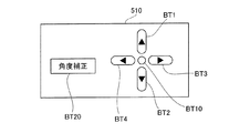
図5は、実施例における操作部510を例示する説明図である。操作部510は、プロジェクタPJの、例えば上面に設置されている。操作部510は、図5に示すように、歪み補正ボタンBT1,BT2,BT3,BT4、決定ボタンBT10、補正実行ボタンBT20を備える。補正形状計算モジュール432は、補正実行ボタンBT20が押下されると、角度パラメータ補正画面WDを表示する。
FIG. 5 is an explanatory diagram illustrating the
図6(a)〜(c)は、実施例における角度パラメータ補正画面WDを例示する説明図である。角度パラメータ補正画面WDは、縦辺補正スライドバーSL1,横辺補正スライドバーSL2および回転補正スライドバーSL3を有する。各スライドバーSL1〜SL3には、それぞれ、現在の角度パラメータθ、φ、ψを表すマークMK1〜MK3が表示されている。選択枠TGは、補正対象のスライドバーを枠で囲んで示している。各スライドバーの図面左右方向の移動量と、各角度パラメータθ、φ、ψの補正量とが連動している。実施例では、縦辺補正スライドバーSL1の移動量と角度パラメータθの補正量とが連動しており、液晶ライトバルブ300に形成される表示領域の形状の縦辺の傾きが補正される。また、横辺補正スライドバーSL2の移動量と角度パラメータφの補正量が連動しており、液晶ライトバルブ300に形成される表示領域の形状の横辺の傾きが補正される。また、回転補正スライドバーSL3の移動量と角度パラメータψの補正量とが連動しており、液晶ライトバルブ300に形成される表示領域がスクリーン法線nを回転軸として回転される。
FIGS. 6A to 6C are explanatory views illustrating the angle parameter correction screen WD in the embodiment. The angle parameter correction screen WD includes a vertical side correction slide bar SL1, a horizontal side correction slide bar SL2, and a rotation correction slide bar SL3. Marks MK1 to MK3 representing the current angle parameters θ, φ, and ψ are displayed on the slide bars SL1 to SL3, respectively. The selection frame TG shows a correction target slide bar surrounded by a frame. The amount of movement of each slide bar in the left-right direction in the drawing is linked to the amount of correction of each angle parameter θ, φ, ψ. In the embodiment, the movement amount of the vertical side correction slide bar SL1 and the correction amount of the angle parameter θ are interlocked, and the inclination of the vertical side of the shape of the display area formed in the liquid crystal
実施例では、ユーザに、角度パラメータθ、φ、ψの順番で入力させるため、角度補正の開始時、図6(a)に示すように、縦辺補正スライドバーSL1が選択枠TGにより選択されている。なお、プロジェクタの電源を入れてから一度も歪み補正を行っていない場合には、角度パラメータθ、φ、および、ψには、それぞれ初期値の「0」が設定されている。 In the embodiment, in order to allow the user to input the angle parameters θ, φ, and ψ in the order, at the start of the angle correction, as shown in FIG. 6A, the vertical side correction slide bar SL1 is selected by the selection frame TG. ing. If the distortion has not been corrected even after the projector is turned on, initial values “0” are set for the angle parameters θ, φ, and ψ, respectively.
図7(a)は、角度パラメータθ、φ、およびψに初期値の「0」が設定されている状態で、プロジェクタをあおり投写した際の表示領域40および形成領域30を表している。図7(a)に示すように、角度補正開始時、表示領域40は台形に歪んでおり、形成領域30は、液晶ライトバルブ300全体に矩形に形成されている。
FIG. 7A shows the
補正形状計算モジュール432は、縦辺補正スライドバーSL1のマークMK1の移動量に応じて、角度パラメータθを補正する(ステップS12)具体的には、ユーザは、スクリーンSCに表示されている画像を視認しながら、補正ボタンBT3もしくはBT4を押下し、図7(b)に示すように、縦辺41,42が略平行となるように縦辺補正スライドバーSL1のマークMKを移動させる。補正形状計算モジュール432は、補正ボタンBT3もしくはBT4の押下される度に、縦辺補正スライドバーSL1に連動する角度パラメータθを補正する。図7(b)に示すように、液晶ライトバルブ300に形成されている形成領域30の縦辺31,32の角度が破線に示すように変化する。ユーザは、縦辺41,42が略平行となったことを確認し、決定ボタンBT10を押下する。これにより。角度パラメータθは、補正角度θ1に補正される。
The correction
決定ボタンBT10の押下により、角度パラメータθ1が確定される。角度パラメータθ1を、式6に代入することにより、形成領域30の垂直消失点Vpが式7に示すように求まる。なお、垂直消失点Vpを通る直線は、スクリーンSC上において平行に表示される。
By pressing the enter button BT10, the angle parameter θ 1 is confirmed. By substituting the angle parameter θ 1 into Equation 6, the vertical vanishing point Vp of the
補正形状計算モジュール432は、決定ボタンBT10の押下を検出すると(ステップS14)、角度パラメータφを補正する(ステップS16)。具体的には、補正形状計算モジュール432は、図6(b)に示すように、角度パラメータ補正画面WDにおいて、横辺補正スライドバーSL2を選択枠TGにより選択する。角度パラメータθの補正時と同様に、ユーザは、図8(a)に示すように、表示領域40を視認しながら、表示領域40の横辺43,44が略平行となるように横辺補正スライドバーSL2のマークMKを移動させる。補正形状計算モジュール432は、補正ボタンBT3もしくはBT4が押下される度に、横辺補正スライドバーSL2に連動する角度パラメータφを補正する。図8(a)に示すように、液晶ライトバルブ300に形成されている形成領域30の横辺33,34が補正される。ユーザは、表示領域40の横辺43,44が略平行となったことを確認し、決定ボタンBT10を押下する。こうすることにより、角度パラメータφは、補正角度φ1補正される。
When the correction
決定ボタンBT10の押下により、角度パラメータφ1が確定される。角度パラメータφ1を、式6に代入することにより、形成領域30の水平消失点Hpが式8に示すように求まる。なお、水平消失点Hpを通る直線は、スクリーンSC上において平行に表示される。
By pressing the enter button BT10, the angle parameter φ 1 is confirmed. By substituting the angle parameter φ 1 into Equation 6, the horizontal vanishing point Hp of the
式8に示すように、水平消失点Hpのy座標は「−tanθ1」であり、垂直消失点のy座標から簡易に求めることができる。従って、角度パラメータφの入力前に角度パラメータθを入力すると、プロジェクタPJの処理負荷を軽減できる。 As shown in Expression 8, the y coordinate of the horizontal vanishing point Hp is “−tan θ 1 ” and can be easily obtained from the y coordinate of the vertical vanishing point. Therefore, if the angle parameter θ is input before the angle parameter φ is input, the processing load on the projector PJ can be reduced.
ここで、角度パラメータθ1と角度パラメータφ1とが決定されると、スクリーン法線は、式5を用いて式9に示すように表される。 Here, when the angle parameter θ 1 and the angle parameter φ 1 are determined, the screen normal is expressed as shown in Equation 9 using Equation 5.
補正形状計算モジュール432は、決定ボタンBT10の押下を検出すると(ステップS18)、ロール角ψを補正対象の角度パラメータとして選択する(ステップS20)。具体的には、補正形状計算モジュール432は、図6(c)に示すように、角度パラメータ補正画面WDにおいて、回転補正スライドバーSL3を選択枠TGにより選択する。角度パラメータθ、φの補正時と同様に、ユーザは、図8(b)に示すように、表示領域40を視認しながら、横辺43,44がスクリーンSCの水平線55に略平行となるように回転補正スライドバーSL3のマークMK3を移動させる。補正形状計算モジュール432は、補正ボタンBT3もしくはBT4が押下される度に、回転補正スライドバーSL3に連動する角度パラメータψを補正する。プロジェクタPJ自体の横転角度は、光軸を回転軸とする回転角度ψ0(図8(b))により表されるが、本実施例のように、角度パラメータの補正時に、角度パラメータθ、φをまず補正することにより、入力された補正角度ψを、スクリーン法線を回転軸とする回転角ψ1に変換して扱うことができる。従って、光軸を回転軸として回転補正した場合には、図8(a)に示す形成領域30がそのままの形状で光軸LAを中心に回転されるが、スクリーン法線を回転軸として回転補正した場合には、図8(b)に示すように、図8(a)に示す形成領域30の形状は補正される。
When the correction
水平消失点Hp、垂直消失点Vpは、回転補正により水平消失点Hp1,垂直消失点Vp1に変換される(式10)が、スクリーンに対する相対的な位置関係は変わらないため、表示領域40の縦辺および横辺の傾きは変わらず、表示領域40は回転補正前後において矩形で維持される。
The horizontal vanishing point Hp and the vertical vanishing point Vp are converted into the horizontal vanishing point Hp1 and the vertical vanishing point Vp1 by the rotation correction (Equation 10), but the relative positional relationship with respect to the screen does not change. The inclination of the side and the side is not changed, and the
ユーザは、図8(b)に示すように、矩形の表示領域40の水平方向の対辺がスクリーンSCの水平線55に略平行となり、表示領域40の垂直方向の対辺がスクリーンSCの垂直線に略平行となったことを確認し、決定ボタンBT10を押下する。
As shown in FIG. 8B, the user has a horizontal opposite side of the
なお、既述のように実施例では、ユーザに角度パラメータθ、φ、ψの順番で入力させるため、例えば、角度パラメータφの補正後に決定ボタンBT10が押下されると、選択枠TGは回転補正スライドバーSL3に移動し、縦辺補正スライドバーSL1、横辺補正スライドバーSL2の選択に戻ることはできない。ユーザは、一度補正した角度パラメータを再度補正するには、一度、角度補正を終了し、補正実行ボタンBT20を再度押下すればよい。 As described above, in the embodiment, in order to allow the user to input the angle parameters θ, φ, and ψ in this order, for example, when the decision button BT10 is pressed after the angle parameter φ is corrected, the selection frame TG is rotated and corrected. It is not possible to move to the slide bar SL3 and return to the selection of the vertical side correction slide bar SL1 and the horizontal side correction slide bar SL2. In order to correct the angle parameter once corrected, the user may end the angle correction once and press the correction execution button BT20 again.
補正実行モジュール434は、決定ボタンBT10の押下を検出すると(ステップS20)、計算された形成領域30の補正形状に基づき、すなわち、補正された各角度パラメータθ1、φ1、ψ1が代入された式4の射影変換Φを用いて、入力画像データから、液晶ライトバルブ300に補正形状の画像を形成するための補正画像データを生成する(ステップS24)。
When the
以上説明した実施例のプロジェクタによれば、スクリーンSCに画像を表示すべき表示領域の形状を略矩形とした後に、スクリーン法線を回転軸として表示領域を回転させて、投写面の水平垂直方向に対する表示領域の歪み(傾き)を補正できる。従って、略矩形とされた表示領域について新たな台形歪みの発生を抑制でき、効率的に表示領域の歪みを補正できる。また、実施例のプロジェクタによれば、角度パラメータθと角度パラメータφとを用いて簡易にスクリーン法線を算出でき、プロジェクタの処理負荷を軽減できる。 According to the projector of the embodiment described above, the shape of the display area on which the image is to be displayed on the screen SC is made substantially rectangular, and then the display area is rotated about the screen normal as the rotation axis, so that the horizontal and vertical directions of the projection plane The distortion (inclination) of the display area with respect to can be corrected. Therefore, the generation of a new trapezoidal distortion can be suppressed for the display area having a substantially rectangular shape, and the distortion of the display area can be efficiently corrected. Further, according to the projector of the embodiment, the screen normal can be easily calculated using the angle parameter θ and the angle parameter φ, and the processing load on the projector can be reduced.
また、実施例のプロジェクタによれば、角度パラメータ補正画面において、角度パラメータθ、φ、ψの、所定の順番での入力を必須とするように制御しているため、各角度パラメータをユーザに円滑に入力させることができる。 Further, according to the projector of the embodiment, since the angle parameters θ, φ, and ψ are controlled to be input in a predetermined order on the angle parameter correction screen, each angle parameter is smoothly transmitted to the user. Can be input.
B.変形例:
(1)実施例では、プロジェクタPJは、歪み補正部を備えており、本発明における画像処理装置およびプロジェクタに相当する。しかしながら、例えば、歪み補正部は、プロジェクタとは異なるパーソナルコンピュータに設けられていてもよい。係る場合には、コンピュータが本発明における画像処理装置に相当する。
B. Variations:
(1) In the embodiment, the projector PJ includes a distortion correction unit, and corresponds to the image processing device and the projector according to the present invention. However, for example, the distortion correction unit may be provided in a personal computer different from the projector. In such a case, the computer corresponds to the image processing apparatus according to the present invention.
(2)実施例でにおいてプロジェクタは、液晶ライトバルブを備えているが、例えば、液晶ライトバルブに代えて、DMD(デジタルマイクロミラーデバイス)(TI社の登録商標)等のマイクロミラー型光変調装置を備えても良い。あるいは、プロジェクタは、高輝度ブラウン管やプラズマディスプレイパネル、エレクトロルミネッセンスディスプレイパネル、発光ダイオード型ディスプレイパネル、フィールドエミッションディスプレイパネルなど備えても良い。このように、画像形成部としては、非自発光型の装置や自発光型の装置を用いることができる。 (2) In the embodiment, the projector includes a liquid crystal light valve. For example, instead of the liquid crystal light valve, a micromirror light modulator such as DMD (digital micromirror device) (registered trademark of TI) is used. May be provided. Alternatively, the projector may include a high-intensity cathode ray tube, a plasma display panel, an electroluminescence display panel, a light emitting diode display panel, a field emission display panel, and the like. Thus, as the image forming unit, a non-self-luminous device or a self-luminous device can be used.
(3)実施例において、ハードウェアによって実現されていた構成の一部をソフトウェアに置き換えるようにしてもよく、逆に、ソフトウェアによって実現されていた構成の一部をハードウェアにおきかえるようにしてもよい。 (3) In the embodiment, a part of the configuration realized by hardware may be replaced by software, and conversely, a part of the configuration realized by software may be replaced by hardware. Good.
以上、本発明の種々の実施例について説明したが、本発明はこれらの実施例に限定されず、その趣旨を逸脱しない範囲で種々の構成をとることができる。 As mentioned above, although the various Example of this invention was described, this invention is not limited to these Examples, A various structure can be taken in the range which does not deviate from the meaning.
30…形成領域
31…縦辺
31…横辺
40…表示領域
41…横辺
43…横辺
55…水平線
100…照明光学系
110…光源ランプ駆動部
300…液晶ライトバルブ
310…液晶ライトバルブ駆動部
340…投写光学系
350…投写光学系調整部
400…CPU
410…画像入力部
420…画像処理部
430…歪み補正部
432…補正形状計算モジュール
434…補正実行モジュール
510…操作部
DESCRIPTION OF
410:
Claims (8)
前記プロジェクタの設置面に対する前記プロジェクタの垂直方向の投写角度に関する第1の補正角度パラメータ、前記設置面に対する前記プロジェクタの水平方向の投写角度に関する第2の補正角度パラメータ、および、前記プロジェクタの光軸に対する前記プロジェクタの回転角度に関する第3の補正角度パラメータと、を入力する入力手段と、
前記入力された第1の補正角度パラメータおよび前記第2の補正角度パラメータを用いて、前記投写面に対して垂直な直線である投写面法線を算出する投写面法線算出手段と、
前記第3の補正角度パラメータを、前記算出された投写面法線を回転軸とする前記プロジェクタの回転角度に変換する変換手段と、
前記第1の補正角度パラメータ、前記第2の補正角度パラメータおよび前記変換された第3の補正角度パラメータを用いて、原画像データから、前記投写面に表示される表示画像の歪みを補正した補正画像データを生成する補正画像データ生成手段と、を備え、
前記入力手段は、前記第3の補正角度パラメータの入力前に、前記投写面に画像を表示するための表示領域の形状を略矩形とするための、前記第1の補正角度パラメータおよび前記第2の補正角度パラメータを入力し、かつ、前記投写面法線の算出後に前記第3の補正角度パラメータを入力する画像処理装置。 An image processing apparatus used in a projector including an image forming unit that forms an image to be displayed on a projection surface using image data,
A first correction angle parameter related to a vertical projection angle of the projector relative to the installation surface of the projector; a second correction angle parameter related to a horizontal projection angle of the projector relative to the installation surface; and an optical axis of the projector Input means for inputting a third correction angle parameter related to the rotation angle of the projector;
A projection plane normal calculating means for calculating a projection plane normal that is a straight line perpendicular to the projection plane, using the input first correction angle parameter and the second correction angle parameter;
Conversion means for converting the third correction angle parameter into a rotation angle of the projector with the calculated projection plane normal as a rotation axis;
Correction using the first correction angle parameter, the second correction angle parameter, and the converted third correction angle parameter to correct distortion of the display image displayed on the projection plane from the original image data Corrected image data generation means for generating image data ,
The input means includes the first correction angle parameter and the second correction parameter for making the shape of a display area for displaying an image on the projection plane substantially rectangular before inputting the third correction angle parameter. correction angular parameters enter the, and, the image processing apparatus to enter the third correction angle parameter after the calculation of the projection plane normal.
前記入力手段は、前記第2の補正角度パラメータの入力前に前記第1の補正角度パラメータを入力し、
前記補正画像データ生成手段は、前記第1の補正角度パラメータ、前記第2の補正角度パラメータおよび前記変換された第3の補正角度パラメータを、入力された順番で用いた式1により表される回転行列Rに従って前記補正画像データを生成する、画像処理装置。
The input means inputs the first correction angle parameter before inputting the second correction angle parameter,
The corrected image data generation means is a rotation represented by Equation 1 using the first correction angle parameter, the second correction angle parameter, and the converted third correction angle parameter in the input order. An image processing apparatus that generates the corrected image data according to a matrix R.
前記第1の補正角度パラメータ、前記第2の補正角度パラメータ、前記第3の補正角度パラメータの順番で、前記各補正角度パラメータをユーザに入力させるための角度パラメータ入力画面を前記投写面に表示する表示制御手段を備える、画像処理装置。 The image processing apparatus according to claim 1, further comprising:
An angle parameter input screen for allowing the user to input each correction angle parameter is displayed on the projection surface in the order of the first correction angle parameter, the second correction angle parameter, and the third correction angle parameter. An image processing apparatus comprising display control means.
請求項1ないし請求項3いずれか記載の画像処理装置と、
光源と、
前記光源からの射出光と、前記画像処理装置から入力された前記補正画像データとを用いて、前記投写面に表示すべき画像を形成する画像形成部と、
前記画像形成部から出力された射出光を投写面に投写する投写光学系と、を備えるプロジェクタ。 A projector,
An image processing apparatus according to any one of claims 1 to 3,
A light source;
An image forming unit that forms an image to be displayed on the projection plane using the light emitted from the light source and the corrected image data input from the image processing device;
A projector comprising: a projection optical system that projects the emitted light output from the image forming unit onto a projection surface;
前記投写面に画像を表示するための表示領域の形状を略矩形とするための、前記プロジェクタの設置面に対する前記プロジェクタの垂直方向の投写角度に関する第1の補正角度パラメータと、前記設置面に対する前記プロジェクタの水平方向の投写角度に関する第2の補正角度パラメータとを、前記プロジェクタの光軸に対する前記プロジェクタの回転角度に関する第3の補正角度パラメータの入力前に入力し、
前記入力された第1の補正角度パラメータおよび前記第2の補正角度パラメータを用いて、前記投写面に対して垂直な直線である投写面法線を算出し、
前記投写面法線の算出後に前記第3の補正角度パラメータを入力し、
前記第3の補正角度パラメータを、前記算出された投写面法線を回転軸とする回転角度に変換し、
前記第1の補正角度パラメータ、前記第2の補正角度パラメータおよび前記変換された第3の補正角度パラメータを用いて、原画像データから、前記投写面に表示される表示画像の歪みを補正した補正画像データを生成する、画像処理方法。 An image processing method executed by an image processing apparatus used in a projector including an image forming unit that forms an image to be displayed on a projection surface using image data,
Wherein for the shape of the display area for displaying an image on a projection surface of a substantially rectangular, and the first correction angle parameter related to the projection angle in the vertical direction of the projector with respect to the installation surface of the projector, the with respect to the installation surface A second correction angle parameter related to a horizontal projection angle of the projector is input before inputting a third correction angle parameter related to the rotation angle of the projector with respect to the optical axis of the projector ;
A projection plane normal that is a straight line perpendicular to the projection plane is calculated using the input first correction angle parameter and the second correction angle parameter,
Input the third correction angle parameter after calculating the projection plane normal ,
Converting the third correction angle parameter into a rotation angle with the calculated projection plane normal as a rotation axis;
Correction using the first correction angle parameter, the second correction angle parameter, and the converted third correction angle parameter to correct distortion of the display image displayed on the projection plane from the original image data An image processing method for generating image data.
前記第1の補正角度パラメータおよび前記第2の補正角度パラメータおよび前記第3の補正角度パラメータの入力において、前記第1の補正角度パラメータを入力し、前記第1の補正角度パラメータの入力後に前記第2の補正角度パラメータを入力し、前記第2の補正角度パラメータの入力後に前記第3の補正角度パラメータを入力する、画像処理方法。 The image processing method according to claim 5, comprising:
In the input of the first correction angle parameter, the second correction angle parameter, and the third correction angle parameter, the first correction angle parameter is input, and the first correction angle parameter is input after the input of the first correction angle parameter. 2. An image processing method, wherein the second correction angle parameter is input, and the third correction angle parameter is input after the second correction angle parameter is input.
前記投写面に画像を表示するための表示領域の形状を略矩形とするための、前記プロジェクタの設置面に対する前記プロジェクタの垂直方向の投写角度に関する第1の補正角度パラメータと、前記設置面に対する前記プロジェクタの水平方向の投写角度に関する第2の補正角度パラメータとを、前記プロジェクタの光軸に対する前記プロジェクタの回転角度に関する第3の補正角度パラメータの入力前に入力する機能と、
前記入力された第1の補正角度パラメータおよび前記第2の補正角度パラメータを用いて、前記投写面に対して垂直な直線である投写面法線を算出する機能と、
前記投写面法線の算出後に前記第3の補正角度パラメータを入力する機能と、
前記第3の補正角度パラメータを、前記算出された投写面法線を回転軸とする回転角度に変換する機能と、
前記第1の補正角度パラメータ、前記第2の補正角度パラメータおよび前記変換された第3の補正角度パラメータを用いて、原画像データから、前記投写面に表示される表示画像の歪みを補正した補正画像データを生成する機能と、を備えるコンピュータプログラム。 A computer program for causing an image processing apparatus used in a projector including an image forming unit that forms an image to be displayed on a projection surface using image data to execute image processing,
Wherein for the shape of the display area for displaying an image on a projection surface of a substantially rectangular, and the first correction angle parameter related to the projection angle in the vertical direction of the projector with respect to the installation surface of the projector, the with respect to the installation surface A function of inputting a second correction angle parameter related to a horizontal projection angle of the projector before inputting a third correction angle parameter related to the rotation angle of the projector with respect to the optical axis of the projector ;
A function of calculating a projection plane normal, which is a straight line perpendicular to the projection plane, using the input first correction angle parameter and the second correction angle parameter;
A function of inputting the third correction angle parameter after calculating the projection plane normal;
A function of converting the third correction angle parameter into a rotation angle with the calculated projection plane normal as a rotation axis;
Correction using the first correction angle parameter, the second correction angle parameter, and the converted third correction angle parameter to correct distortion of the display image displayed on the projection plane from the original image data And a function of generating image data.
Priority Applications (1)
| Application Number | Priority Date | Filing Date | Title |
|---|---|---|---|
| JP2007164970A JP5320693B2 (en) | 2007-06-22 | 2007-06-22 | Image processing device, projector |
Applications Claiming Priority (1)
| Application Number | Priority Date | Filing Date | Title |
|---|---|---|---|
| JP2007164970A JP5320693B2 (en) | 2007-06-22 | 2007-06-22 | Image processing device, projector |
Publications (2)
| Publication Number | Publication Date |
|---|---|
| JP2009005148A JP2009005148A (en) | 2009-01-08 |
| JP5320693B2 true JP5320693B2 (en) | 2013-10-23 |
Family
ID=40321041
Family Applications (1)
| Application Number | Title | Priority Date | Filing Date |
|---|---|---|---|
| JP2007164970A Expired - Fee Related JP5320693B2 (en) | 2007-06-22 | 2007-06-22 | Image processing device, projector |
Country Status (1)
| Country | Link |
|---|---|
| JP (1) | JP5320693B2 (en) |
Cited By (2)
| Publication number | Priority date | Publication date | Assignee | Title |
|---|---|---|---|---|
| CN102169281A (en) * | 2010-02-25 | 2011-08-31 | 株式会社尼康 | Projector |
| TWI768672B (en) * | 2021-01-22 | 2022-06-21 | 偉詮電子股份有限公司 | Projector focusing method and projector focusing system |
Families Citing this family (4)
| Publication number | Priority date | Publication date | Assignee | Title |
|---|---|---|---|---|
| JP6197322B2 (en) * | 2013-03-22 | 2017-09-20 | カシオ計算機株式会社 | Projection device, image output device, projection method, and projection program |
| JP6201359B2 (en) * | 2013-03-22 | 2017-09-27 | カシオ計算機株式会社 | Projection system, projection method, and projection program |
| JP6364899B2 (en) * | 2014-04-08 | 2018-08-01 | セイコーエプソン株式会社 | Projector, projector control method, and program |
| JP7180372B2 (en) * | 2018-12-28 | 2022-11-30 | セイコーエプソン株式会社 | Projector control method and projector |
Family Cites Families (8)
| Publication number | Priority date | Publication date | Assignee | Title |
|---|---|---|---|---|
| JP2001069433A (en) * | 1999-08-25 | 2001-03-16 | Ricoh Co Ltd | Image projector, image projection method, and computer- readable recording medium recording program to allow computer to execute the method |
| AU1763801A (en) * | 1999-11-12 | 2001-06-06 | Brian S. Armstrong | Methods and appparatus for measuring orientation and distance |
| US6520647B2 (en) * | 2000-08-17 | 2003-02-18 | Mitsubishi Electric Research Laboratories Inc. | Automatic keystone correction for projectors with arbitrary orientation |
| JP2005024668A (en) * | 2003-06-30 | 2005-01-27 | Sharp Corp | Projection type display device and method for installing and adjusting projection type display device |
| JP4371018B2 (en) * | 2004-09-14 | 2009-11-25 | セイコーエプソン株式会社 | Display device |
| JP4617960B2 (en) * | 2005-03-29 | 2011-01-26 | ブラザー工業株式会社 | Projection device |
| JP2006317546A (en) * | 2005-05-10 | 2006-11-24 | Seiko Epson Corp | Projector and projector control method |
| JP4774826B2 (en) * | 2005-06-23 | 2011-09-14 | カシオ計算機株式会社 | Projection apparatus, projection control method, and program |
-
2007
- 2007-06-22 JP JP2007164970A patent/JP5320693B2/en not_active Expired - Fee Related
Cited By (4)
| Publication number | Priority date | Publication date | Assignee | Title |
|---|---|---|---|---|
| CN102169281A (en) * | 2010-02-25 | 2011-08-31 | 株式会社尼康 | Projector |
| CN102169281B (en) * | 2010-02-25 | 2014-11-26 | 株式会社尼康 | projector |
| TWI768672B (en) * | 2021-01-22 | 2022-06-21 | 偉詮電子股份有限公司 | Projector focusing method and projector focusing system |
| US11558591B2 (en) | 2021-01-22 | 2023-01-17 | Weltrend Semiconductor Inc. | Projector focusing method and projector focusing system capable of projecting high resolution images at arbitrary positions |
Also Published As
| Publication number | Publication date |
|---|---|
| JP2009005148A (en) | 2009-01-08 |
Similar Documents
| Publication | Publication Date | Title |
|---|---|---|
| JP4006601B2 (en) | Image processing system, projector, program, information storage medium, and image processing method | |
| JP4363354B2 (en) | Distortion correction processing for projectors | |
| CN101656858B (en) | Projection display apparatus and display method | |
| JP5320693B2 (en) | Image processing device, projector | |
| CN101515107B (en) | Projector, electronic device and method for controlling projector | |
| JP4493113B2 (en) | Projector and projection image correction apparatus | |
| JP5481833B2 (en) | Projector and projector control method | |
| JP3844076B2 (en) | Image processing system, projector, program, information storage medium, and image processing method | |
| JP5098869B2 (en) | Image processing apparatus, image display apparatus, and image data generation method | |
| CN101990079A (en) | Projector and trapezoidal distortion correcting method | |
| JP2009206800A (en) | Image processing apparatus, projector and image processing method | |
| JP2005124131A (en) | Image processing system, projector, program, information storage medium, and image processing method | |
| JP5251010B2 (en) | Image processing device, projector | |
| JP4831219B2 (en) | Projector and projector control method | |
| US20110242421A1 (en) | Image distortion correction apparatus and method | |
| JP2008211355A (en) | Projector, program, and information storage medium | |
| JP4199641B2 (en) | Projector device | |
| JP5194578B2 (en) | Image processing device, projector | |
| JP5187480B2 (en) | Projector, program, information storage medium, and image generation method | |
| JP5374837B2 (en) | Image processing for projectors | |
| JP5029154B2 (en) | Image processing for projectors | |
| JP4985950B2 (en) | Projector, projection method, program, and information storage medium | |
| JP2009168887A (en) | Portable image projector | |
| JP2009135972A (en) | Projector, program, and information storage medium | |
| JP2024065831A (en) | Display method, display device, image generating device, and program |
Legal Events
| Date | Code | Title | Description |
|---|---|---|---|
| A621 | Written request for application examination |
Free format text: JAPANESE INTERMEDIATE CODE: A621 Effective date: 20100617 |
|
| A977 | Report on retrieval |
Free format text: JAPANESE INTERMEDIATE CODE: A971007 Effective date: 20120418 |
|
| A131 | Notification of reasons for refusal |
Free format text: JAPANESE INTERMEDIATE CODE: A131 Effective date: 20120515 |
|
| A521 | Request for written amendment filed |
Free format text: JAPANESE INTERMEDIATE CODE: A523 Effective date: 20120709 |
|
| A131 | Notification of reasons for refusal |
Free format text: JAPANESE INTERMEDIATE CODE: A131 Effective date: 20130219 |
|
| A521 | Request for written amendment filed |
Free format text: JAPANESE INTERMEDIATE CODE: A523 Effective date: 20130418 |
|
| TRDD | Decision of grant or rejection written | ||
| A01 | Written decision to grant a patent or to grant a registration (utility model) |
Free format text: JAPANESE INTERMEDIATE CODE: A01 Effective date: 20130618 |
|
| A61 | First payment of annual fees (during grant procedure) |
Free format text: JAPANESE INTERMEDIATE CODE: A61 Effective date: 20130701 |
|
| R150 | Certificate of patent or registration of utility model |
Ref document number: 5320693 Country of ref document: JP Free format text: JAPANESE INTERMEDIATE CODE: R150 Free format text: JAPANESE INTERMEDIATE CODE: R150 |
|
| S531 | Written request for registration of change of domicile |
Free format text: JAPANESE INTERMEDIATE CODE: R313531 |
|
| R350 | Written notification of registration of transfer |
Free format text: JAPANESE INTERMEDIATE CODE: R350 |
|
| LAPS | Cancellation because of no payment of annual fees |