JP2008074157A - ECU case assembly structure - Google Patents
ECU case assembly structure Download PDFInfo
- Publication number
- JP2008074157A JP2008074157A JP2006252859A JP2006252859A JP2008074157A JP 2008074157 A JP2008074157 A JP 2008074157A JP 2006252859 A JP2006252859 A JP 2006252859A JP 2006252859 A JP2006252859 A JP 2006252859A JP 2008074157 A JP2008074157 A JP 2008074157A
- Authority
- JP
- Japan
- Prior art keywords
- ecu
- case
- connector
- assembled
- box
- Prior art date
- Legal status (The legal status is an assumption and is not a legal conclusion. Google has not performed a legal analysis and makes no representation as to the accuracy of the status listed.)
- Pending
Links
Images


Landscapes
- Connection Or Junction Boxes (AREA)
- Connector Housings Or Holding Contact Members (AREA)
Abstract
【課題】ECU搭載集中ボックス側のコネクタとECUケース側のコネクタとのピン孔の数が不一致な場合であっても、ECU搭載集中BOXの内部にECUケースを組み付けること構造を提供すること、且つ、そのときのECU搭載集中ボックスの構造を簡便な構造とすることを課題とする。
【解決手段】外部に雄型コネクタ11を有するECUケース10と、貫通孔20aを有する枠形状のECU搭載集中ボックス20と、前記雄型コネクタ11と接続可能な雌型コネクタ31を有すると共に前記貫通孔20aに嵌め込み可能に形成されたコネクタホルダー30とを備え、前記ECU搭載集中ボックス20の貫通孔20aの一方から前記コネクタホルダー30を挿入して組み付け、その組み付け状態で、前記貫通孔20aの他方から前記ECUケース10を挿入して組み付けることにより両コネクタ11、31同士の接続をも完了する。
【選択図】図1An object of the present invention is to provide a structure for assembling an ECU case inside an ECU-mounted concentration BOX even when the number of pin holes between the connector mounted on the ECU-mounted concentration box and the connector on the ECU case does not match. An object of the present invention is to make the structure of the ECU-mounted concentration box at that time a simple structure.
An ECU case 10 having a male connector 11 on the outside, a frame-shaped ECU mounting concentration box 20 having a through hole 20a, a female connector 31 connectable to the male connector 11, and the through hole. And a connector holder 30 formed so as to be fitted in the hole 20a. The connector holder 30 is inserted and assembled from one of the through holes 20a of the ECU mounting concentration box 20, and the other of the through holes 20a is assembled in the assembled state. The ECU case 10 is inserted and assembled to complete the connection between the connectors 11 and 31.
[Selection] Figure 1
Description
本発明は、ECU搭載集中BOXの内部にECUケースを組み付ける構造に関する。 The present invention relates to a structure for assembling an ECU case inside an ECU-mounted centralized BOX.
従来より、車両内には、複数個のECUケースが搭載されている。この搭載について詳述すると、複数個のECUケースは、区画された複数のスペースを有するECU集中搭載BOXの各スペース内にそれぞれ挿入されて組み付けられている。そして、このECU集中搭載BOXは、車両内の所定の場所に組み付けられている。 Conventionally, a plurality of ECU cases are mounted in a vehicle. To describe this mounting in detail, the plurality of ECU cases are respectively inserted and assembled in the spaces of the ECU central mounting BOX having a plurality of partitioned spaces. And this ECU concentration mounting BOX is assembled | attached to the predetermined place in a vehicle.
なお、この出願の発明に関連する先行技術文献情報としては、例えば、特許文献1が知られている。
しかしながら、上述したECUケース組み付け構造では、以下(1)〜(2)に記す課題を有していた。
(1)ECU搭載集中ボックスの内部に複数個のECUケースを組み付ける際、ECUケースを保持させるための強度がECU搭載集中ボックスに必要となるため、ECU搭載集中ボックスの内部に仕切壁を設けることで、ECU搭載集中ボックスの強度を向上させていた。このとき、複数個のECUケースは、仕切壁によって区画される各スペースに組み付けられていた。このように、ECU搭載集中ボックスの内部に仕切壁を設ける必要があったため、ECU搭載集中ボックスの内部が複雑な構造となっていた。
(2)ECU搭載集中ボックスの内部にECUケースを組み付ける際、ECUケースはコネクタを介してECU搭載集中ボックス外部のワイヤーハーネスと電気的に接続されている。このとき、コネクタのピン孔の数は、ECUケースの内部に搭載される制御基板の種類によって異なることがあるため、外形サイズの同じECUケースであっても、コネクタのピン孔の数が一致しなければ、ECUケースを組み付けることができなかった。そのため、コネクタのピン孔の種類の数だけ専用のECU搭載集中ボックスが必要となっていた。
However, the above-described ECU case assembly structure has the following problems (1) to (2).
(1) When assembling a plurality of ECU cases inside the ECU mounting concentration box, the ECU mounting concentration box needs strength to hold the ECU case, so a partition wall is provided inside the ECU mounting concentration box. Therefore, the strength of the centralized box equipped with the ECU was improved. At this time, the plurality of ECU cases are assembled in each space partitioned by the partition wall. Thus, since it was necessary to provide a partition wall inside the ECU mounting concentration box, the inside of the ECU mounting concentration box had a complicated structure.
(2) When the ECU case is assembled inside the ECU mounting concentration box, the ECU case is electrically connected to a wire harness outside the ECU mounting concentration box via a connector. At this time, since the number of pin holes of the connector may differ depending on the type of control board mounted inside the ECU case, the number of pin holes of the connector is the same even in the ECU case having the same outer size. Without it, the ECU case could not be assembled. Therefore, dedicated ECU-equipped concentration boxes are required for the number of types of connector pin holes.
本発明は、このような課題を解決しようとするもので、その目的は、ECU搭載集中ボックス側のコネクタとECUケース側のコネクタとのピン孔の数が不一致な場合であっても、ECU搭載集中BOXの内部にECUケースを組み付けること構造を提供すること、且つ、そのときのECU搭載集中ボックスの構造を簡便な構造とすることを課題とする。 The present invention is intended to solve such a problem, and its purpose is to mount an ECU even if the number of pin holes between the connector on the ECU mounting central box side and the connector on the ECU case side does not match. It is an object of the present invention to provide a structure for assembling an ECU case inside a central BOX, and to make the structure of the ECU-mounted central box at that time a simple structure.
本発明は、上記の目的を達成するためのものであって、以下のように構成されている。
請求項1に記載の発明は、外部に雄型コネクタを有するECUケースと、貫通孔を有する枠形状のECU搭載集中ボックスと、前記雄型コネクタと接続可能な雌型コネクタを有すると共に前記貫通孔に嵌め込み可能に形成されたコネクタホルダーとを備え、前記ECU搭載集中ボックスの貫通孔の一方から前記コネクタホルダーを挿入して組み付け、その組み付け状態で、前記貫通孔の他方から前記ECUケースを挿入して組み付けることにより両コネクタ同士の接続をも完了する構成のECUケース組み付け構造である。
この構成によれば、ECU搭載集中ボックス20の強度だけでなく、さらにコネクタホルダー30の強度も利用して、ECUケース10をECU搭載集中ボックス20の内部に組み付けることができる。したがって、ECU搭載集中ボックス20の内部に仕切壁を設ける必要がなくなるため、ECU搭載集中ボックス20の構造が簡便なものとなる。
また、この構成によれば、例えば、ECUケースの雄型コネクタのピン孔の数が異なるECUケースをECU搭載集中ボックスに組み付けたい場合、そのピン孔の数に対応するコネクタホルダーに入れ替えれば、ECU搭載集中ボックスを入れ替える必要なく組み付けることができる。したがって、ECU搭載集中ボックスの共通化を図ることができる。
The present invention is for achieving the above object, and is configured as follows.
The invention according to claim 1 includes an ECU case having a male connector outside, a frame-shaped ECU mounting concentration box having a through hole, a female connector connectable to the male connector, and the through hole. A connector holder formed so that it can be fitted into the ECU, and the connector holder is inserted and assembled from one of the through holes of the ECU mounting concentration box, and the ECU case is inserted from the other of the through holes in the assembled state. This is an ECU case assembly structure that completes the connection between the two connectors.
According to this configuration, the
Further, according to this configuration, for example, when an ECU case having a different number of pin holes of the male connector of the ECU case is to be assembled to the ECU mounting central box, the ECU holder can be replaced with a connector holder corresponding to the number of pin holes. It can be assembled without the need to replace the mounting box. Therefore, it is possible to share the ECU-mounted concentration box.
以下、本発明を実施するための最良の形態を、図面を用いて説明する。
(実施例1)
まず、図1〜4によって実施例1を説明する。
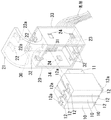
図1は、実施例1におけるECUケース10をECU搭載集中ボックス20の内部に組み付ける前の斜視図である。図2は、図1の組み付け工程を説明する図である。図3は、図2の次工程を説明する図である。図4は、図3のECU搭載集中ボックス20を車両内に組み付けた斜視図である。なお、以下の説明にあたって「前後、左右、上下」の各方向は、「図1の斜視図における、前後、左右、上下」の各方向である。
Hereinafter, the best mode for carrying out the present invention will be described with reference to the drawings.
(Example 1)
First, Embodiment 1 will be described with reference to FIGS.
FIG. 1 is a perspective view before the
また、実施例1では、3つのECUケース10をECU搭載集中ボックス20の内部に組み付ける場合を説明しており、これら各ECUケース10の相違点は、雄型コネクタ11内のピン孔の数である。具体的には、図1の一部拡大図からも明らかなように、雄型コネクタ11内のピン孔の数は、左のECUケース10から順に「12、8、10」である。なお、これらのことは、後述する、実施例2においても同様である。
Further, in the first embodiment, a case where three
まず、図1を参照して、ECUケース10、ECU搭載集中ボックス20およびコネクタホルダー30を個別に説明する。はじめに、ECUケース10を説明する。ECUケース10は、車両(図示しない)に搭載されている電装品を制御するための制御基板(図示しない)を収容したケースである。
First, the
ECUケース10の後面には、雄型コネクタ11が設けられている。この雄型コネクタ11とケース10内の制御基板とは電気的に接続されている。また、この雄型コネクタ11は、後述するコネクタホルダー30の雌型コネクタ31と接続可能となっている。この雌型コネクタ31はワイヤーハーネスW/Hによって車両内に搭載された電装品と接続されているため、ECUケース10の雄型コネクタ11とコネクタホルダー30の雌型コネクタ31とを接続させることで、ECUケース10内の制御基板と車両内に搭載されている電装品が電気的に接続されることになる。これにより、制御基板によって電装品の制御が可能となっている。
A
また、ECUケース10の上下面には、自由端側が撓み可能な略L字形状の係止片12がそれぞれ形成されており、これら係止片12の外方面には、それぞれ突起爪12aが形成されている。ここで外方面とは、図1において、上側の係止片12では上面のことであり、下側の係止片12では下面のことである。これら両突起爪12aは、後述するコネクタホルダー30に形成の係止孔32に嵌め込み可能となっている。なお、このECUケース10は、例えば、剛性を有する樹脂によって一体成形されている。
Further, on the upper and lower surfaces of the
次に、ECU搭載集中ボックス20を説明する。ECU搭載集中ボックス20は、四角枠状に形成されており、その前後方向に貫通する貫通孔20aが形成されている。この貫通孔20aの後側から後述するコネクタホルダー30を挿入して組み付け可能となっている。ECU搭載集中ボックス20の上面には、車両内に設けられたリーンフォースメント40(図4参照)を挟み込み可能な断面略C字形状の挟持体21が形成されている。
Next, the ECU mounting
この挟持体21の内周面の上下には、自由端側が撓み可能な略L字形状の係止片22が対向するようにそれぞれ形成されており、これら係止片22の外方面には、それぞれ突起爪22aが形成されている。ここで外方面とは、図1において、上側の係止片22では下面のことであり、下側の係止片22では下面のことである。これら両突起爪12aは、リーンフォースメント40に形成の係止孔(図示しない)に嵌め込み可能となっている。なお、この両係止片22は、挟持体21の内周面の左右に一対形成されている、そのため、挟持体21の内周面には、上下左右に合計4つの係止片22が形成されている。
On the upper and lower sides of the inner peripheral surface of the
また、ECU搭載集中ボックス20の下面の後側には、垂下片23が下方に向けて延設されており、この垂下片23の後面には嵌合体23aが突設されている。この嵌合体23aは、車両内に設けられたブラケット50(図4参照)に形成の係止孔(図示しない)に嵌め込み可能となっている。また、ECU搭載集中ボックス20両側面の上下には、それぞれ係止孔24が形成されている。これら4つの係止孔24には、後述するコネクタホルダー30に形成の係止突起34を嵌め込み可能となっている。なお、このECU搭載集中ボックス20は、ECUケース10と同様に、例えば、剛性を有する樹脂によって一体成形されている。
A hanging
次に、コネクタホルダー30を説明する。コネクタホルダー30は、前面側が開放した略四角箱形状となっている。このコネクタホルダー30は、既に説明したように、ECU搭載集中ボックス20の貫通孔20aに嵌め込み可能となっている。また、コネクタホルダー30の内部には、既に説明したように、ECUケース10の雄型コネクタ11と接続可能な雌型コネクタ31が形成されている。また、コネクタホルダー30の上面には、既に説明したように、ECUケース10の突起爪12aを嵌め込み可能な係止孔32が形成されている。また、コネクタホルダー30の左右の両側面には、既に説明したように、ECU搭載集中ボックス20に形成の各係止孔24に嵌め込み可能な係止突起34が左右に2個ずつ形成されている。
Next, the
また、コネクタホルダー30の後面には、フランジ33が形成されている。このフランジ33によって、ECU搭載集中ボックス20の貫通孔20aの後方からコネクタホルダー30を挿入して組み付けたとき、コネクタホルダー30がECU搭載集中ボックス20の内部に全て挿入されることを防止している。なお、このコネクタホルダー30は、ECUケース10およびECU搭載集中ボックス20と同様に、例えば、剛性を有する樹脂によって一体成形されている。
A
続いて、図2、3を参照して、上述したECU搭載集中BOX20の内部にECUケース10を組み付ける構造について説明する。まず、ECU搭載集中ボックス20の貫通孔20aの後方からコネクタホルダー30を挿入していく。このとき、コネクタホルダー30のフランジ33がECU搭載集中ボックス20の後面と当接するまでコネクタホルダー30を挿入していく。そして、フランジ33がECU搭載集中ボックス20の後面と当接すると、コネクタホルダー30の係止突起34がECU搭載集中ボックス20の係止孔24に嵌め込まれる。これにより、コネクタホルダー30はECU搭載集中ボックス20の内部に挿入して組み付けられた状態となる(図2参照)。
2 and 3, the structure for assembling the
次に、この状態で、ECU搭載集中ボックス20の貫通孔20aの前方からECUケース10を挿入していく。すると、ECUケース10の両突起爪12aはコネクタホルダー30の内面に押し当てられるため、ECUケース10の両係止片12は、互いに近づく方向に撓み始める。さらに、ECUケース10を挿入すると、ECUケース10の突起爪12aはコネクタホルダー30の係止孔32に嵌め込まれ、ECUケース10の両係止片12の撓みは解消される。これにより、ECUケース10はコネクタホルダー30の内部に挿入して組み付けられた状態となる。
Next, in this state, the
また、この状態のとき、ECUケース10の雄型コネクタ11とコネクタホルダー30の雌型コネクタ31との接続も完了している。このようにして、ECUケース10はコネクタホルダー30の内部、すなわち、ECU搭載集中ボックス20の内部に組み付けられる(図3参照)。
In this state, the connection between the
この組み付け状態で、まず、ECU搭載集中ボックス20の垂下片23の嵌合体23aを傾斜状態で車両のブラケット50の係止孔に嵌め込ませ、この嵌め込ませ部位を回動支点として傾斜状態が鉛直状態となるように回動させていき、ECU搭載集中ボックス20の挟持体21の突起爪22aを車両のリーンフォースメント40の係止孔に嵌め込ませて、ECU搭載集中ボックス20を車両内に組み付けることができる(図4参照)。
In this assembled state, first, the
上述したECUケース10の組み付け構造によれば、まず、ECU搭載集中ボックス20の内部にコネクタホルダー30が嵌め込まれて組み付けられている。そのため、ECUケース10を保持させるための強度として、ECU搭載集中ボックス20の強度だけでなく、さらにコネクタホルダー30の強度も利用することができる。したがって、従来技術で説明したように、ECU搭載集中ボックス20の内部に仕切壁を設ける必要がなくなるため、ECU搭載集中ボックス20の構造が簡便なものとなる。
According to the assembly structure of the
また、ECUケース10の雄型コネクタ11のピン孔の数が異なるECUケース10をECU搭載集中ボックス20に組み付けたい場合、そのピン孔の数に対応するコネクタホルダー30に入れ替えれば、ECU搭載集中ボックス20を入れ替える必要がない。例えば、図2の状態から、ピン孔の数が異なる3つのECUケース10(例えば、ピン孔の数が「11、7、9」のECUケース10)を組み付けたい場合、そのままでは、ピン孔の数が不一致のため組み付けることはできない。しかし、コネクタホルダー30をピン孔の数が「11、7、9」に対応するコネクタホルダー30に入れ替えると、ECU搭載集中ボックス20を変更することなく、ピン孔の数が異なる3つのECUケース10をECU搭載集中ボックス20の内部に組み付けることができる。すなわち、ECU搭載集中ボックス20の共通化を図ることができる。
Further, when the
(実施例2)
次に、図5〜8によって実施例2を説明する。
図5は、実施例2におけるECUケース10をECU搭載集中ボックス20の内部に組み付ける前の斜視図である。図6は、図5の組み付け工程を説明する図である。図7は、図6の次工程を説明する図である。図8は、図7のECU搭載集中ボックス20を車両内に組み付けた斜視図である。
(Example 2)
Next, Example 2 will be described with reference to FIGS.
FIG. 5 is a perspective view before the
この実施例2は、実施例1と比較すると、ECUケース10とコネクタホルダー30の組み付けの係止構造が相違したものである。以下の説明にあたって、実施例1と同一もしくは均等な部材の構成には、同一符号を付すことで、重複する説明は省略する。
The second embodiment is different from the first embodiment in the locking structure for assembling the
図5に示すように、ECUケース10の上下面には、実施例1で説明した係止片12の代わりにコネクタホルダー30の係止孔32に相当する係止壁13が設けられている。また、コネクタホルダー30前側における上下端部には、実施例1で説明した係止孔32の代わりにECUケース10の係止片12に相当する係止片35が設けられている。そして、このコネクタホルダー30の係止片35の突起爪35aは、ECUケース10の上記係止壁13と係止可能となっている。そのため、この実施例2においても、ECUケース10をコネクタホルダー30の内部に挿入して組み付けることができる。
As shown in FIG. 5, locking
また、その他の構成は、実施例1と同一構成であるため、実施例1と同様にして、コネクタホルダー30をECU搭載集中ボックス20の内部に挿入して組み付けることができる(図6参照)。また、同様にして、ECUケース10をECU搭載集中ボックス20の内部に組み付けることができる(図7参照)。また、同様にして、ECU搭載集中ボックス20を車両内に組み付けることができる(図8参照)。したがって、実施例2においても、実施例1と同様な作用効果を得ることができる。
Further, since the other configuration is the same as that of the first embodiment, the
上述した内容は、あくまでも本発明の一実施の形態に関するものであって、本発明が上記内容に限定されることを意味するものではない。
各実施例では、ECU搭載集中ボックス20の共通化を図る例として、ECUケース10の雄型コネクタ11のピン孔の数が相違する場合でも可能となる例を説明した。しかし、これに限定されるものではなく、ECUケース10の外形サイズが相違する場合であっても構わない。その場合、コネクタホルダー30の外側サイズはECU搭載集中ボックス20に適応させるように設けておき、コネクタホルダー30の内側サイズ(コネクタホルダー30の内部におけるECUケース10を嵌め込むサイズ)はECUケース10の外形サイズに適応させるように設ければよい。そうすれば、外形サイズの異なるECUケース10であっても、上記各実施例と同様に、コネクタホルダー30のみを入れ替えればECU搭載集中ボックス20に組み付けることができる。
The contents described above are only related to one embodiment of the present invention, and do not mean that the present invention is limited to the above contents.
In each of the embodiments, as an example in which the ECU mounting
10 ECUケース
11 雄型コネクタ
20 ECU搭載集中ボックス
20a 貫通孔
30 コネクタホルダー
31 雌型コネクタ
10
Claims (1)
貫通孔を有する枠形状のECU搭載集中ボックスと、
前記雄型コネクタと接続可能な雌型コネクタを有すると共に前記貫通孔に嵌め込み可能に形成されたコネクタホルダーとを備え、
前記ECU搭載集中ボックスの貫通孔の一方から前記コネクタホルダーを挿入して組み付け、その組み付け状態で、前記貫通孔の他方から前記ECUケースを挿入して組み付けることにより両コネクタ同士の接続をも完了する構成のECUケース組み付け構造。
An ECU case having a male connector outside;
A frame-shaped ECU-mounted concentration box having a through hole;
A connector holder having a female connector connectable with the male connector and formed so as to be fitted into the through hole;
The connector holder is inserted and assembled from one of the through holes of the ECU mounting concentration box, and in the assembled state, the ECU case is inserted and assembled from the other of the through holes to complete the connection between both connectors. The ECU case assembly structure.
Priority Applications (1)
| Application Number | Priority Date | Filing Date | Title |
|---|---|---|---|
| JP2006252859A JP2008074157A (en) | 2006-09-19 | 2006-09-19 | ECU case assembly structure |
Applications Claiming Priority (1)
| Application Number | Priority Date | Filing Date | Title |
|---|---|---|---|
| JP2006252859A JP2008074157A (en) | 2006-09-19 | 2006-09-19 | ECU case assembly structure |
Publications (1)
| Publication Number | Publication Date |
|---|---|
| JP2008074157A true JP2008074157A (en) | 2008-04-03 |
Family
ID=39346678
Family Applications (1)
| Application Number | Title | Priority Date | Filing Date |
|---|---|---|---|
| JP2006252859A Pending JP2008074157A (en) | 2006-09-19 | 2006-09-19 | ECU case assembly structure |
Country Status (1)
| Country | Link |
|---|---|
| JP (1) | JP2008074157A (en) |
Cited By (3)
| Publication number | Priority date | Publication date | Assignee | Title |
|---|---|---|---|---|
| JP2021057987A (en) * | 2019-09-30 | 2021-04-08 | 矢崎総業株式会社 | Electric connection box unit |
| US12142102B2 (en) | 2019-03-25 | 2024-11-12 | Assa Abloy Ab | Ultra-wide band device for access control reader system |
| US12212964B2 (en) | 2019-03-25 | 2025-01-28 | Assa Abloy Ab | Reader coordination for access control |
Citations (3)
| Publication number | Priority date | Publication date | Assignee | Title |
|---|---|---|---|---|
| JPH0745978A (en) * | 1993-07-28 | 1995-02-14 | Toyota Motor Corp | Electronic control unit mounting structure |
| JP2005153590A (en) * | 2003-11-21 | 2005-06-16 | Yazaki Corp | ECU device |
| JP2006032422A (en) * | 2004-07-12 | 2006-02-02 | Denso Corp | Housing structure of electronic control apparatus |
-
2006
- 2006-09-19 JP JP2006252859A patent/JP2008074157A/en active Pending
Patent Citations (3)
| Publication number | Priority date | Publication date | Assignee | Title |
|---|---|---|---|---|
| JPH0745978A (en) * | 1993-07-28 | 1995-02-14 | Toyota Motor Corp | Electronic control unit mounting structure |
| JP2005153590A (en) * | 2003-11-21 | 2005-06-16 | Yazaki Corp | ECU device |
| JP2006032422A (en) * | 2004-07-12 | 2006-02-02 | Denso Corp | Housing structure of electronic control apparatus |
Cited By (5)
| Publication number | Priority date | Publication date | Assignee | Title |
|---|---|---|---|---|
| US12142102B2 (en) | 2019-03-25 | 2024-11-12 | Assa Abloy Ab | Ultra-wide band device for access control reader system |
| US12212964B2 (en) | 2019-03-25 | 2025-01-28 | Assa Abloy Ab | Reader coordination for access control |
| US12495299B2 (en) | 2019-03-25 | 2025-12-09 | Assa Abloy Ab | Physical access control systems with localization-based intent detection |
| JP2021057987A (en) * | 2019-09-30 | 2021-04-08 | 矢崎総業株式会社 | Electric connection box unit |
| JP7068252B2 (en) | 2019-09-30 | 2022-05-16 | 矢崎総業株式会社 | Electrical junction box unit |
Similar Documents
| Publication | Publication Date | Title |
|---|---|---|
| EP1944836B1 (en) | Electrical connection box and assembling method of electrical connection box | |
| JP5423700B2 (en) | Case for electronic unit and method for manufacturing electronic unit | |
| JP5333849B2 (en) | Electrical junction box | |
| JP4958684B2 (en) | connector | |
| JP2006269632A (en) | Electric circuit board storage box | |
| JP5060849B2 (en) | connector | |
| JP2020013730A (en) | Electric connector | |
| JP5758251B2 (en) | door mirror | |
| US20100236825A1 (en) | Assemble structure of connection device and electric device, connection device and electric device used for the same | |
| CN115642432A (en) | electrical junction box | |
| JP2008074157A (en) | ECU case assembly structure | |
| JP4547282B2 (en) | Connector for automatic alignment | |
| JP2010177205A (en) | Wire harness for vehicle, and wiring method of vehicle | |
| JP5342533B2 (en) | Automotive relay box | |
| JP6093645B2 (en) | Joint connector | |
| JP2007227404A (en) | Joint connector | |
| JP6004539B2 (en) | connector | |
| JP2015185257A (en) | Connector device for easy confirmation of connector mating condition | |
| JP2005285512A (en) | Multipolar connector | |
| JP2011072095A (en) | Joint box for automobile use | |
| JP5367388B2 (en) | Connector mating structure | |
| JP4695051B2 (en) | ECU case assembly structure | |
| CN207984940U (en) | Turn to involucrum bridging arrangement and automobile | |
| KR20080086581A (en) | Connector assembly | |
| JP5074962B2 (en) | Connector unit |
Legal Events
| Date | Code | Title | Description |
|---|---|---|---|
| A621 | Written request for application examination |
Free format text: JAPANESE INTERMEDIATE CODE: A621 Effective date: 20090824 |
|
| A977 | Report on retrieval |
Free format text: JAPANESE INTERMEDIATE CODE: A971007 Effective date: 20111118 |
|
| A02 | Decision of refusal |
Free format text: JAPANESE INTERMEDIATE CODE: A02 Effective date: 20120327 |